EP3231968A1 - Baumaschine - Google Patents
Baumaschine Download PDFInfo
- Publication number
- EP3231968A1 EP3231968A1 EP15867373.1A EP15867373A EP3231968A1 EP 3231968 A1 EP3231968 A1 EP 3231968A1 EP 15867373 A EP15867373 A EP 15867373A EP 3231968 A1 EP3231968 A1 EP 3231968A1
- Authority
- EP
- European Patent Office
- Prior art keywords
- authentication
- engine
- vehicle body
- portable key
- range
- Prior art date
- Legal status (The legal status is an assumption and is not a legal conclusion. Google has not performed a legal analysis and makes no representation as to the accuracy of the status listed.)
- Granted
Links
- 238000010276 construction Methods 0.000 claims description 22
- 239000007858 starting material Substances 0.000 description 33
- 230000005540 biological transmission Effects 0.000 description 31
- 230000007246 mechanism Effects 0.000 description 14
- 239000000446 fuel Substances 0.000 description 12
- 238000002347 injection Methods 0.000 description 10
- 239000007924 injection Substances 0.000 description 10
- 239000003921 oil Substances 0.000 description 8
- 239000010720 hydraulic oil Substances 0.000 description 6
- 238000001514 detection method Methods 0.000 description 3
- 238000006073 displacement reaction Methods 0.000 description 3
- 230000005611 electricity Effects 0.000 description 3
- 239000004576 sand Substances 0.000 description 3
- 239000003795 chemical substances by application Substances 0.000 description 2
- 238000004378 air conditioning Methods 0.000 description 1
- 230000003247 decreasing effect Effects 0.000 description 1
- 238000010586 diagram Methods 0.000 description 1
- 239000002828 fuel tank Substances 0.000 description 1
- 230000007935 neutral effect Effects 0.000 description 1
Images


Classifications
-
- E—FIXED CONSTRUCTIONS
- E02—HYDRAULIC ENGINEERING; FOUNDATIONS; SOIL SHIFTING
- E02F—DREDGING; SOIL-SHIFTING
- E02F9/00—Component parts of dredgers or soil-shifting machines, not restricted to one of the kinds covered by groups E02F3/00 - E02F7/00
- E02F9/20—Drives; Control devices
- E02F9/2025—Particular purposes of control systems not otherwise provided for
-
- E—FIXED CONSTRUCTIONS
- E02—HYDRAULIC ENGINEERING; FOUNDATIONS; SOIL SHIFTING
- E02F—DREDGING; SOIL-SHIFTING
- E02F3/00—Dredgers; Soil-shifting machines
- E02F3/04—Dredgers; Soil-shifting machines mechanically-driven
- E02F3/28—Dredgers; Soil-shifting machines mechanically-driven with digging tools mounted on a dipper- or bucket-arm, i.e. there is either one arm or a pair of arms, e.g. dippers, buckets
- E02F3/30—Dredgers; Soil-shifting machines mechanically-driven with digging tools mounted on a dipper- or bucket-arm, i.e. there is either one arm or a pair of arms, e.g. dippers, buckets with a dipper-arm pivoted on a cantilever beam, i.e. boom
- E02F3/32—Dredgers; Soil-shifting machines mechanically-driven with digging tools mounted on a dipper- or bucket-arm, i.e. there is either one arm or a pair of arms, e.g. dippers, buckets with a dipper-arm pivoted on a cantilever beam, i.e. boom working downwardly and towards the machine, e.g. with backhoes
- E02F3/325—Backhoes of the miniature type
-
- B—PERFORMING OPERATIONS; TRANSPORTING
- B60—VEHICLES IN GENERAL
- B60R—VEHICLES, VEHICLE FITTINGS, OR VEHICLE PARTS, NOT OTHERWISE PROVIDED FOR
- B60R25/00—Fittings or systems for preventing or indicating unauthorised use or theft of vehicles
- B60R25/20—Means to switch the anti-theft system on or off
- B60R25/24—Means to switch the anti-theft system on or off using electronic identifiers containing a code not memorised by the user
-
- E—FIXED CONSTRUCTIONS
- E02—HYDRAULIC ENGINEERING; FOUNDATIONS; SOIL SHIFTING
- E02F—DREDGING; SOIL-SHIFTING
- E02F3/00—Dredgers; Soil-shifting machines
- E02F3/04—Dredgers; Soil-shifting machines mechanically-driven
- E02F3/28—Dredgers; Soil-shifting machines mechanically-driven with digging tools mounted on a dipper- or bucket-arm, i.e. there is either one arm or a pair of arms, e.g. dippers, buckets
- E02F3/30—Dredgers; Soil-shifting machines mechanically-driven with digging tools mounted on a dipper- or bucket-arm, i.e. there is either one arm or a pair of arms, e.g. dippers, buckets with a dipper-arm pivoted on a cantilever beam, i.e. boom
- E02F3/32—Dredgers; Soil-shifting machines mechanically-driven with digging tools mounted on a dipper- or bucket-arm, i.e. there is either one arm or a pair of arms, e.g. dippers, buckets with a dipper-arm pivoted on a cantilever beam, i.e. boom working downwardly and towards the machine, e.g. with backhoes
-
- E—FIXED CONSTRUCTIONS
- E02—HYDRAULIC ENGINEERING; FOUNDATIONS; SOIL SHIFTING
- E02F—DREDGING; SOIL-SHIFTING
- E02F3/00—Dredgers; Soil-shifting machines
- E02F3/04—Dredgers; Soil-shifting machines mechanically-driven
- E02F3/96—Dredgers; Soil-shifting machines mechanically-driven with arrangements for alternate or simultaneous use of different digging elements
- E02F3/963—Arrangements on backhoes for alternate use of different tools
- E02F3/964—Arrangements on backhoes for alternate use of different tools of several tools mounted on one machine
-
- E—FIXED CONSTRUCTIONS
- E02—HYDRAULIC ENGINEERING; FOUNDATIONS; SOIL SHIFTING
- E02F—DREDGING; SOIL-SHIFTING
- E02F9/00—Component parts of dredgers or soil-shifting machines, not restricted to one of the kinds covered by groups E02F3/00 - E02F7/00
- E02F9/20—Drives; Control devices
- E02F9/2058—Electric or electro-mechanical or mechanical control devices of vehicle sub-units
- E02F9/2062—Control of propulsion units
-
- E—FIXED CONSTRUCTIONS
- E02—HYDRAULIC ENGINEERING; FOUNDATIONS; SOIL SHIFTING
- E02F—DREDGING; SOIL-SHIFTING
- E02F9/00—Component parts of dredgers or soil-shifting machines, not restricted to one of the kinds covered by groups E02F3/00 - E02F7/00
- E02F9/24—Safety devices, e.g. for preventing overload
-
- E—FIXED CONSTRUCTIONS
- E02—HYDRAULIC ENGINEERING; FOUNDATIONS; SOIL SHIFTING
- E02F—DREDGING; SOIL-SHIFTING
- E02F9/00—Component parts of dredgers or soil-shifting machines, not restricted to one of the kinds covered by groups E02F3/00 - E02F7/00
- E02F9/26—Indicating devices
- E02F9/264—Sensors and their calibration for indicating the position of the work tool
- E02F9/265—Sensors and their calibration for indicating the position of the work tool with follow-up actions (e.g. control signals sent to actuate the work tool)
-
- E—FIXED CONSTRUCTIONS
- E05—LOCKS; KEYS; WINDOW OR DOOR FITTINGS; SAFES
- E05B—LOCKS; ACCESSORIES THEREFOR; HANDCUFFS
- E05B49/00—Electric permutation locks; Circuits therefor ; Mechanical aspects of electronic locks; Mechanical keys therefor
-
- F—MECHANICAL ENGINEERING; LIGHTING; HEATING; WEAPONS; BLASTING
- F02—COMBUSTION ENGINES; HOT-GAS OR COMBUSTION-PRODUCT ENGINE PLANTS
- F02N—STARTING OF COMBUSTION ENGINES; STARTING AIDS FOR SUCH ENGINES, NOT OTHERWISE PROVIDED FOR
- F02N11/00—Starting of engines by means of electric motors
- F02N11/08—Circuits or control means specially adapted for starting of engines
-
- B—PERFORMING OPERATIONS; TRANSPORTING
- B60—VEHICLES IN GENERAL
- B60R—VEHICLES, VEHICLE FITTINGS, OR VEHICLE PARTS, NOT OTHERWISE PROVIDED FOR
- B60R2325/00—Indexing scheme relating to vehicle anti-theft devices
- B60R2325/30—Vehicles applying the vehicle anti-theft devices
- B60R2325/308—Industrial vehicles
-
- F—MECHANICAL ENGINEERING; LIGHTING; HEATING; WEAPONS; BLASTING
- F02—COMBUSTION ENGINES; HOT-GAS OR COMBUSTION-PRODUCT ENGINE PLANTS
- F02D—CONTROLLING COMBUSTION ENGINES
- F02D29/00—Controlling engines, such controlling being peculiar to the devices driven thereby, the devices being other than parts or accessories essential to engine operation, e.g. controlling of engines by signals external thereto
- F02D29/04—Controlling engines, such controlling being peculiar to the devices driven thereby, the devices being other than parts or accessories essential to engine operation, e.g. controlling of engines by signals external thereto peculiar to engines driving pumps
-
- F—MECHANICAL ENGINEERING; LIGHTING; HEATING; WEAPONS; BLASTING
- F02—COMBUSTION ENGINES; HOT-GAS OR COMBUSTION-PRODUCT ENGINE PLANTS
- F02D—CONTROLLING COMBUSTION ENGINES
- F02D29/00—Controlling engines, such controlling being peculiar to the devices driven thereby, the devices being other than parts or accessories essential to engine operation, e.g. controlling of engines by signals external thereto
- F02D29/06—Controlling engines, such controlling being peculiar to the devices driven thereby, the devices being other than parts or accessories essential to engine operation, e.g. controlling of engines by signals external thereto peculiar to engines driving electric generators
-
- H—ELECTRICITY
- H04—ELECTRIC COMMUNICATION TECHNIQUE
- H04L—TRANSMISSION OF DIGITAL INFORMATION, e.g. TELEGRAPHIC COMMUNICATION
- H04L9/00—Cryptographic mechanisms or cryptographic arrangements for secret or secure communications; Network security protocols
- H04L9/32—Cryptographic mechanisms or cryptographic arrangements for secret or secure communications; Network security protocols including means for verifying the identity or authority of a user of the system or for message authentication, e.g. authorization, entity authentication, data integrity or data verification, non-repudiation, key authentication or verification of credentials
Definitions
- the present invention relates to a construction machine such as a hydraulic excavator, a wheel loader, a hydraulic crane and the like, for example, and particularly to a construction machine including a wireless authenticating device for performing wireless authentication with a portable key device.
- the construction machine such as a hydraulic excavator, a hydraulic crane and the like starts/stops an engine on the basis of an operation of a key switch by an operator. More specifically, the operator of the construction machine inserts a plate-shaped or rod-shaped key into a key cylinder of a key switch when the engine is to be started and rotates this key. In this case, when a key groove of the key and a key cylinder groove match each other, the key becomes rotatable.
- Patent Document 1 By the operator, the key is rotated to any one of an "OFF” position where electric equipment of the construction machine is not conducted and the engine is stopped, an "ON” position where the electric equipment is conducted, and a "START” position where the engine is started (a starter motor of the engine is rotated) (Patent Document 1), for example.
- engine start of the construction machine is performed in a state where a position of a gate lock lever provided in the vicinity of an operator's seat is set to a lock position (prohibition position) where driving of a hydraulic actuator is prohibited.
- the starter motor of the engine is rotated, and the engine is started.
- the key returns from the position of "START” to the position of "ON", and an "engine driven/conduction ON” state is brought about where the electric equipment is conducted in a state where the engine is driven.
- Patent Document 1 Japanese Patent Laid-Open No. 2013-155564 A
- the present invention was made in view of the aforementioned problem of the conventional art and has an object to provide a construction machine which can simplify a start operation of the engine.
- a construction machine of the present invention comprises: a vehicle body; an engine provided on the vehicle body and serving as a power source; a hydraulic pump driven by the engine and supplying a pressurized oil; a hydraulic actuator driven by the pressurized oil supplied from the hydraulic pump; and a lock device switched between a lock position prohibiting driving of the hydraulic actuator and an unlock position allowing the driving of the hydraulic actuator, wherein a work is performed by the driving of the hydraulic actuator in a state where the lock device is switched to the unlock position.
- a characteristic of a configuration adopted by the present invention includes a power switch for starting the engine; a wireless authentication device provided on the vehicle body and performing wireless authentication with a portable key device; a vehicle body controller allowing or prohibiting start of the engine on the basis of an operation of the power switch and authentication by the wireless authentication device, wherein the wireless authentication device is constituted to transmit an authentication request signal within an authenticable range and to perform authentication when an authentication signal replied from the portable key device is received on the basis of the transmitted authentication request signal; and the vehicle body controller is constituted to allow start of the engine by the power switch when the lock device is switched to the lock position and wireless authentication device performs authentication by portable key device.
- a start operation of the engine can be simplified.
- a hydraulic excavator 1 as a construction machine is a small-sized hydraulic excavator called a mini excavator suitable for a work in a small work site.
- the hydraulic excavator 1 is constituted by including a automotive crawler-type lower traveling structure 2, an upper revolving structure 4 mounted on the lower traveling structure 2 capable of revolving through a revolving device 3, and a working mechanism 5 provided on a front side of the upper revolving structure 4, capable of tilting and lifting thereto.
- the hydraulic excavator 1 performs an excavating work of earth and sand by using the working mechanism 5.
- the lower traveling structure 2 and the upper revolving structure 4 constitute a vehicle body of the hydraulic excavator 1.
- the small-sized hydraulic excavator 1 Since the small-sized hydraulic excavator 1 is used in a demolishing work of an inside of a building, the excavating work in a small place such as in a street and the like, a machine weight is kept to approximately 0.8 to 8 tons, for example.
- the lower traveling structure 2 is constituted by a truck frame 2A, drive wheels 2B provided on both left and right sides of the truck frame 2A, idler wheels 2C provided on the both left and right sides of the truck frame 2A and on sides opposite to the drive wheels 2B in a front-rear direction, and a crawler belt 2D wound around the drive wheel 2B and the idler wheel 2C (only left side is shown for the both).
- the left and right drive wheels 2B are rotated/driven by left and right traveling hydraulic motors (not shown) as hydraulic actuators, respectively.
- the working mechanism 5 is constituted as a swing-post type working mechanism, for example.
- the working mechanism 5 includes a swing post 5A, a boom 5B, an arm 5C, and a bucket 5D as a work tool.
- the working mechanism 5 includes a swing cylinder (not shown) for causing the swing post 5A (and thus, the entire working mechanism 5) to swing left and right, a boom cylinder 5E for rotating the boom 5B, an arm cylinder 5F for rotating the arm 5C, and a bucket cylinder 5G as a work tool cylinder for rotating the bucket 5D.
- the swing cylinder, the boom cylinder 5E, the arm cylinder 5F, and the bucket cylinder 5G constitute hydraulic actuators driven by pressurized oil, respectively.
- the upper revolving structure 4 is mounted on the lower traveling structure 2 through the revolving device 3 constituted by including a revolving hydraulic motor as the hydraulic actuator, a speed reduction mechanism, and a revolving bearing.
- the upper revolving structure 4 is revolved/driven by the revolving device 3 with respect to the lower traveling structure 2.
- the upper revolving structure 4 is constituted by including a revolving frame 6, an exterior cover 7, a cab 8, and a counterweight 14 which will be described later.
- the revolving frame 6 is a frame forming a support structural body of the upper revolving structure 4, and the revolving frame 6 is mounted on the lower traveling structure 2 through the revolving device 3.
- the counterweight 14 and an engine 15 which will be described later are provided on a rear part side thereof
- the cab 8 which will be described later is provided on a front left side
- a fuel tank and a hydraulic oil tank (none of them are shown) are provided on a front right side.
- the exterior cover 7 is provided on the revolving frame from the right side of the cab 8 to the rear side and left and right side surface sides.
- the exterior cover 7 defines a machine room accommodating the engine 15, a hydraulic pump 17, a heat exchanger (not shown) and the like together with the revolving frame 6, the cab 8, and the counterweight 14.
- the cab 8 is mounted on the front left side of the revolving frame 6, and an inside of the cab 8 forms an operator's room which an operator (driver) gets onboard.
- An operator's seat 9 on which the operator is seated is provided in the inside of the cab 8.
- An operating lever 10 for work for operating the working mechanism 5 is provided on the both left and right sides of the operator's seat 9.
- An operating lever/pedal 11 for traveling operated by a manual operation or a stepping-on operation when the lower traveling structure 2 is made to run is provided on a front of the operator's seat 9.
- a power switch 12 is provided on a rear side of the right operating lever 10 on the right side of the operator's seat 9.
- the power switch 12 is a main switch for starting the engine 15.
- This power switch 12 is constituted by a push-type switch, for example, and operated (pressed) by the operator.
- the power switch 12 is connected to a vehicle body controller 39 which will be described later.
- the power switch 12 When the power switch 12 is operated by the operator, it outputs a signal (ON signal) indicating conduction to the vehicle body controller 39.
- the operator can start, stop or the like of the engine 15 which will be described later by seating on the operator's seat 9 and operating the power switch 12.
- a gate lock lever 13 is provided on a lower side of the left-side work operating lever 10 and at a position corresponding to an entrance way of the cab 8.
- the gate lock lever 13 constitutes a lock device together with a gate lock switch 13A which will be described later.
- the gate lock lever 13 is rotated/displaced between a boarding restricted position (hereinafter referred to as an unlock position) shutting off the entrance way of the cab 8 and a boarding allowed position (hereinafter referred to as a lock position) opening the entrance way.
- the unlock position which shuts off the entrance way corresponds to a state where the gate lock lever 13 is lowered
- the lock position opening the entrance way corresponds to a state where the gate lock lever 13 is opened.
- the gate lock lever 13 in the lowered state is shown in Fig. 1 .
- the gate lock lever 13 is switched by an operation by the operator between the lock position (raised position) and the unlock position (lowered position).
- the hydraulic actuator of the hydraulic excavator 1 that is, driving of various hydraulic actuators such as each of the cylinders 5E, 5F, and 5G, the traveling hydraulic motor, the revolving hydraulic motor and the like is prohibited.
- the gate lock lever 13 is set to the unlock position, driving of the hydraulic actuators is allowed.
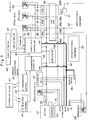
- the gate lock switch 13A (see Fig. 3 ) is provided on the gate lock lever 13.
- the gate lock switch 13A is a detection switch for detecting a position of the gate lock lever 13.
- the gate lock switch 13A is connected to the vehicle body controller 39 which will be described later.
- the vehicle body controller 39 can determine whether the gate lock lever 13 is at a lock position or at an unlock position on the basis of a detection signal (ON/OFF signal) of the gate lock switch 13A.
- the gate lock switch 13A can be constituted as a normally-open switch which is in a non-conducted (OFF) state when the gate lock lever 13 is at the lock position and in a conducted (ON) state when at the unlock position, for example.
- the vehicle body controller 39 is connected to a pilot cut relay 33 which will be described later.
- a battery 21 and a pilot pressure switching valve 31 which will be described later are connected through the pilot cut relay 33.
- the pilot pressure can be supplied to the control valve through the operating lever 10 for work and the operating lever/pedal 11 for traveling. More specifically, when the vehicle body controller 39 determines that the gate lock lever 13 is at the unlock position from the gate lock switch 13A, it turns ON (closes) the pilot cut relay 33 and brings the pilot pressure switching valve 31 to a conducted state (ON) on the basis of the supply (power feed) of electricity from the battery 21. In this case, the control valve is switched, and driving of the hydraulic actuator is allowed on the basis of the operation of the operating lever 10 and the operating lever/pedal 11 for traveling by the operator. As described above, the hydraulic excavator 1 performs a work by driving of the hydraulic actuator in the state where the gate lock lever 13 is switched to the unlock position.
- the counterweight 14 is to take a weight balance with the working mechanism 5.
- the counterweight 14 is located on a rear side of the engine 15 which will be described later and mounted on a rear end portion of the revolving frame 6.
- a rear surface side of the counterweight 14 is formed having an arc shape.
- the counterweight 14 has constitution accommodated in a vehicle width of the lower traveling structure 2. Therefore, the hydraulic excavator 1 constitutes a rear-small-revolving type mini excavator.
- the engine 15 is provided on the upper revolving structure 4. Specifically, the engine 15 is disposed in a lateral state on a rear side of the revolving frame 6 constituting the upper revolving structure 4.
- the engine 15 is constituted by using a small-sized diesel engine, for example, and becomes a power source for the hydraulic pump 17 which will be described later.
- the engine 15 is constituted by an electronically controlled type engine and its fuel supply amount is variably controlled by a fuel injection device including an electronically controlled injection valve (injector), for example. That is, the fuel injection device variably controls a fuel injection amount injected into a cylinder of the engine 15 on the basis of a control signal output from an engine control unit 34 (see Fig. 3 ) called ECU which will be described later.
- a starter motor 16 is provided in the engine 15.
- the starter motor 16 is an electrical component (auxiliary machine) of the engine 15, that is, electric equipment device of the engine 15.
- the starter motor 16 is connected to the battery 21 through a starter relay 23 or the like which will be described later.
- the starter motor 16 is to rotate a crank shaft of the engine 15 when the engine 15 is to be started. That is, when the starter relay 23 is turned ON (closed), the starter motor 16 is rotated on the basis of power feed from the battery 21, and the engine 15 can be started.
- the starter relay 23 is turned OFF (opened), and the starter motor 16 is stopped.
- the hydraulic pump 17 is mounted on a left side of the engine 15.
- the hydraulic pump 17 constitutes a hydraulic source together with the hydraulic oil tank. That is, the hydraulic pump 17 suctions the hydraulic oil from the hydraulic oil tank by being driven by the engine 15 and supplies the suctioned hydraulic oil as the pressurized oil toward the control valve, not shown.
- the hydraulic pump 17 is constituted by a variable displacement type swash-plate type, an inclined shaft type or a radial piston type hydraulic pump, for example. It should be noted that the hydraulic pump 17 does not necessarily have to be the variable displacement type hydraulic pump but may be constituted by using a fixed displacement type hydraulic pump, for example.
- control valve (not shown) is switched in accordance with the pilot pressure supplied on the basis of the operation of the operating lever 10 for work and the operating lever/pedal 11 for traveling.
- the control valve selectively supplies or delivers the pressurized oil delivered from the hydraulic pump 17 to or from various hydraulic actuators including each of the cylinders 5E, 5F, and 5G, the traveling hydraulic motor, and the revolving hydraulic motor.
- the battery 21 is a power source for various electric equipment including the engine 15. More specifically, the battery 21 is a power source for the electric equipment for driving the engine 15 such as the starter motor 16 provided in the engine 15, the fuel injection device (injector), various sensors, and moreover, the engine control unit 34 (hereinafter referred to as an ECU 34) and the like, for example. In addition, the battery 21 is a power source for various electric equipment mounted on the hydraulic excavator 1 such as a first electrical component 27, a second electrical component 30, a monitor device 38, the vehicle body controller 39, an authentication controller 45 and the like, for example.
- the battery 21 is a power source for various electric equipment mounted on the hydraulic excavator 1 such as a first electrical component 27, a second electrical component 30, a monitor device 38, the vehicle body controller 39, an authentication controller 45 and the like, for example.
- the starter motor 16 is connected to the battery 21 through a slow-blow fuse 22 (hereinafter referred to as an SB fuse 22) called S.B.F. and the starter relay 23 and constitutes a starter circuit.
- the starter relay 23 is connected to the battery 21 through the SB fuse 22, a C fuse 24, a C relay 25, and a C fuse 26A in a fuse box 26 and constitutes a C-relay circuit.
- the C relay 25 is switched between ON and OFF by the vehicle body controller 39 which will be described later.
- the C relay 25 is turned ON, an electric current flows through the ECU 34 and the starter relay 23.
- the ECU 34 turns ON the starter relay 23 and brings the starter motor 16 and the battery 21 in the conducted state.
- the starter motor 16 is rotated, and the engine 15 can be started.
- the starter relay 23 is turned OFF.
- the first electrical component 27 is connected to the battery 21 through the SB fuse 22, an accessory fuse 28 (hereinafter referred to as an ACC fuse 28), an accessory relay 29 (hereinafter referred to as an ACC relay 29), an ACC fuse 26B in the fuse box 26 and constitutes an accessory circuit (ACC circuit).
- the first electrical component 27 corresponds to electric equipment conducted to the battery 21 when the ACC relay 29 connected to the vehicle body controller 39 is ON.
- the first electrical component 27 is not conducted to the battery 21 when the ACC relay 29 connected to the vehicle body controller 39 is OFF.
- the first electrical component 27 is also called an accessory electrical component (ACC electrical component).
- This first electrical component 27 includes a part of the monitor device 38, a part of the controller (controllers other than the vehicle body controller 39 and the authentication controller 45, for example), an air conditioning device, a wiper, various solenoid valves and the like, for example.
- the first electrical component 27 also includes electric equipment required for driving of the engine 15 such as a fuel injection device of the engine 15 and the like, for example.
- the second electrical component 30 is connected to the battery 21 through the SB fuse 22 and a B fuse 26C in the fuse box 26.
- the second electrical component 30 corresponds to electric equipment connected to the battery 21 at all times regardless of ON/OFF of the C relay 25, the ACC relay 29, and the pilot cut relay 33 which will be described later connected to the vehicle body controller 39.
- the second electrical component 30 is also called a battery directly-connected electrical component or a B electrical component.
- This second electrical component 30 includes a part of the monitor device 38, the vehicle body controller 39, the authentication controller 45, a horn, a light and the like, for example.
- the pilot pressure switching valve 31 is also called a pilot cut solenoid valve.
- the pilot pressure switching valve 31 is provided between a pilot pump, not shown, and the control valve, for example.
- the pilot pressure switching valve 31 switches between allowing and prohibition of supply of the pilot pressure to the control valve, that is, between conduction and shut-off of the pilot pressurized oil.
- the pilot pressure switching valve 31 is connected to the battery 21 through the SB fuse 22, the pilot cut fuse 32, the pilot cut relay 33, and a PC fuse 26D in the fuse box 26.
- the pilot cut relay 33 is connected to the vehicle body controller 39.
- the vehicle body controller 39 switches ON/OFF of the pilot cut relay 33 in accordance with a signal of the gate lock switch 13A corresponding to the position of the gate lock lever 13.
- the pilot cut relay 33 When the pilot cut relay 33 is ON, the pilot pressure switching valve 31 and the battery 21 are conducted, and the pilot pressure switching valve 31 is brought into the conducted state. As a result, the pilot pressure can be supplied to the control valve through the operating lever 10 for work and the operating lever/pedal 11 for traveling, and driving of the hydraulic actuator (the swing cylinder, the boom cylinder 5E, the arm cylinder 5F, the bucket cylinder 5G, the revolving hydraulic motor, the traveling hydraulic motor) is allowed. On the other hand, when the pilot cut relay 33 is OFF, the pilot pressure switching valve 31 and the battery 21 are not conducted, and the pilot pressure switching valve 31 is brought into the shut-off state. In this case, the pilot pressure cannot be supplied to the control valve, and driving of the hydraulic actuator is prohibited.
- the ECU 34 is a control device performing rotation number control and the like of the engine 15 and this ECU 34 is constituted by a microcomputer or the like, for example.
- the ECU 34 is connected to the various sensors and the fuel injection device provided in the engine 15.
- the ECU 34 operates the engine 15 at a rotation number according to the driving operation by the operator, an operating state of the vehicle and the like by variably controlling the fuel injection amount (fuel supply amount) into the cylinder of the engine 15, for example.
- the ECU 34 controls the fuel injection amount of the fuel injection device on the basis of an instruction of an engine rotation number instruction dial operated by the operator and an instruction from the vehicle body controller 39.
- the ECU 34 is connected to the battery 21 through the SB fuse 22, an ECU fuse 26E in the fuse box 26, and a main relay 35. Moreover, the ECU 34 is connected to the starter relay 23, an alternator 37, and the ACC relay 29. The main relay 35 is switched ON/OFF by the ECU 34. That is, when the ACC relay 29 is turned ON, an electric current flows from the ACC relay 29 to the ECU 34, and the ECU 34 turns ON the main relay 35. As a result, the ECU 34 is brought into the conducted state with the battery 21. Moreover, the ECU 34 is mutually connected to the monitor device 38, the vehicle body controller 39, the authentication controller 45 and the like through a communication line 36 and constitutes a CAN (Control Area Network).
- CAN Control Area Network
- the alternator 37 generates power by being driven by the engine 15.
- the alternator 37 feeds power to the first electrical component 27, the second electrical component 30, the ECU 34, the monitor device 38, the vehicle body controller 39, the authentication controller 45 and the like in addition to storage of electricity (charging) of the battery 21.
- the alternator 37 has its B terminal connected to the battery 21 through the SB fuse 22, a P terminal and an I terminal connected to the ECU 34, and an L terminal connected to the monitor device 38.
- the monitor device 38 is provided in the cab 8 of the hydraulic excavator 1, for example, and notifies an operation state of the hydraulic excavator 1 and the like to the operator manipulating the hydraulic excavator 1. More specifically, the monitor device 38 displays information to be notified to the operator. That is, the monitor device 38 displays information such as various state amounts including an engine rotation number, a remaining fuel amount, a remaining oil amount and the like, nonconformity information, alarm information and the like of the engine 15 and various devices including hydraulic devices, for example. Moreover, as will be described later, authentication holding time, the authenticable range of the wireless authentication device 42, and a setting screen for setting them and the like are displayed on the monitor device 38.
- the monitor device 38 is constituted by including a display screen, a display light, an alarm lamp, a selection switch, and a horn to be used as an acoustic device, for example.
- the monitor device 38 is to be used as a notifying device for notifying information to the operator.
- the vehicle body controller 39 is a control device or a control unit integrally managing the monitor device 38, the ECU 34, and the authentication controller 45.
- the vehicle body controller 39 is constituted by including a microcomputer and the like, for example.
- the vehicle body controller 39 switches conduction (ON) and non-conduction (OFF) between the battery 21 and the electric equipment on the basis of the wireless authentication with the portable key device 41 performed by the wireless authentication device 42 which will be described later and the operation of the power switch 12 by the operator.
- the vehicle body controller 39 switches conduction and non-conduction between the battery 21 and the first electrical component 27 and conduction and non-conduction between the battery 21 and the starter motor 16 on the basis of the authentication of the wireless authentication device 42 and the operation of the power switch 12.
- the vehicle body controller 39 allows or prohibits start of the engine 15 on the basis of the result of the authentication (whether it is an authenticated state or an unauthenticated state) by the wireless authentication device 42 and presence or absence of the operation of the power switch 12.
- the portable key device 41 is also called an electronic key or a portable machine. This portable key device 41 is held by a manager such as the operator operating the hydraulic excavator 1, a site foreman of a work site, an owner of the hydraulic excavator 1 and the like.
- a request signal authentication request signal
- ID code authentication signal, authentication number
- the portable key device 41 includes a receiver for receiving the request signal, a transmitter for transmitting the ID code to an RF reception antenna 44 of the authentication controller 45, a microcomputer for controlling them, a battery for supplying electricity to them, a transponder for which the ID code is set and the like (none of them are shown) .
- the transponder collates (authenticates) the ID code by being brought close to an antenna (not shown) for the transponder provided on the vehicle body when the battery of the portable key device 41 is exhausted.
- the portable key device 41 when the portable key device 41 comes within a transmission range (LF band) of the LF transmission antenna 43 connected to the authentication controller 45, it receives the request signal (authentication request signal) transmitted from the LF transmission antenna 43 by the receiver.
- the portable key device 41 transmits the ID code for authentication set to the portable key device 41 through the transmitter on the basis of this reception.
- the wireless authentication device 42 is provided in the upper revolving structure 4 (in the cab 8, for example) which is a vehicle body side.
- the wireless authentication device 42 performs wireless authentication with the portable key device 41.
- the wireless authentication device 42 transmits the request signal in the authenticable range and performs authentication when the ID code for authentication replied from the portable key device 41 on the basis of the transmitted request signal is received.
- the wireless authentication device 42 is constituted by including one or a plurality of the LF transmission antennas 43 as a transmission antenna, one or a plurality of the RF reception antennas 44 as a reception antenna, and the authentication controller 45.
- the LF transmission antenna 43 is connected to the authentication controller 45 and transmits the request signal (authentication request signal) indicating that the ID code for authentication is transmitted to the portable key device 41 at all times at a predetermined control cycle (0.5 second-cycle, for example).
- the RF reception antenna 44 is connected to the authentication controller 45 and receives the ID code transmitted from the portable key device 41.
- a transmission range (LF band) of the LF transmission antenna 43 is smaller than a reception range (RF band) of the RF reception antenna 44.
- the transmission range (LF band) of the LF transmission antenna 43 has a diameter of approximately 1 meter around the operator's seat 9, for example.
- the reception range (RF band) of the RF reception antenna 44 has a diameter of approximately 10 meters around the operator's seat 9, for example.
- the transmission range (authenticable range) of the LF transmission antenna 43 can be variably set by a range setting switch 48 within a range having a diameter of approximately 1 to 10 meters around the operator's seat 9, for example.
- the authentication controller 45 is constituted by a microcomputer and this authentication controller 45 is connected to the vehicle body controller 39 through the communication line 36 and an analog signal line 46 which is a communication line different from the communication line 36.
- the authentication controller 45 is a control device for wireless authentication which performs wireless authentication of the portable key device 41. That is, the authentication controller 45 transmits the request signal to the authenticable range through the LF transmission antenna 43 at the predetermined control cycle (0.5-second cycle, for example) .
- the authentication controller 45 authenticates (determines) whether the ID code from the portable key device 41 received through the RF reception antenna 44 is a valid ID code or not, that is, whether it matches the ID code allowed for start of the engine 15 set in advance in the authentication controller 45 or not.
- the authentication controller 45 outputs an authentication result (determination result) to the vehicle body controller 39 at all times at a predetermined control cycle (0.5-second cycle, for example).
- the authentication controller 45 when the authentication controller 45 receives a valid ID code from the portable key device 41 through the RF reception antenna 44, it determines to be valid authentication. That is, in this case, the authentication controller 45 outputs a fact (valid authentication: the fact that the portable key device 41 is within the authenticable range) that the portable key device 41 transmitting the valid ID code is present in the transmission range (LF band in Fig. 4 ) of the LF transmission antenna 43 to the vehicle body controller 39.
- the authentication controller 45 has not received the valid ID code (including reception of an invalid ID code), it determines to be unauthenticated.
- the authentication controller 45 outputs a fact that there is no portable key device 41 transmitting the valid ID code within the transmission range of the LF transmission antenna 43 (unauthentication: the fact that the portable key device 41 is not within the authenticable range) to the vehicle body controller 39.
- the authentication controller 45 is constituted to hold the authenticated state for predetermined authentication holding time after it received the valid ID code replied from the portable key device 41. That is, when the authentication controller 45 receives the valid ID code from the portable key device 41, it holds the state of valid authentication for the predetermined holding time after that even if a valid ID code is not received. In other words, the authentication controller 45 continuously outputs the valid authentication to the vehicle body controller 39.
- the authentication holding time can be variably set by the manager of the hydraulic excavator 1.
- a time setting switch 47 as a time setting unit which can variably set the authentication holding time of the wireless authentication device 42 is connected to the vehicle body controller 39. The setting of the authentication holding time can be made the time setting switch 47 while an authentication holding time setting screen is displayed on the monitor device 38 by increasing/decreasing the authentication holding time (seconds, minutes, hours, days, for example) displayed on this screen, for example.
- the authentication holding time is set to 10 to 30 seconds (short time) which is basic time.
- the basic time is set as time assumed to be restored normally even if transmission/reception of the ID code between the portable key device 41 and the wireless authentication device 42 cannot be performed temporarily on the basis of electromagnetic interference caused by disturbance, for example. That is, the basic time is set in advance as waiting time until a communication environment is normally restored.
- the site foreman of the work site of the hydraulic excavator 1 can set the authentication holding time to long time such as 2 to 3 hours, for example. In this case, even if the site foreman leaves the hydraulic excavator 1 for a meeting or the like while holding the portable key device 41, the operator can start the engine 15 of the hydraulic excavator 1 at the work site during this period. Moreover, a rental agent or a lease agent of the hydraulic excavator 1 can also set the authentication holding time, that is, time during which start of the engine 15 of the hydraulic excavator 1 can be performed as a rental period or a lease period.
- the authentication controller 45 transmits the request signal within the predetermined authenticable range through the LF transmission antenna 43.
- this authenticable range transmission range of the LF transmission antenna 43
- the range setting switch 48 as a range setting unit which can variably set the authenticable range of the wireless authentication device 42 is connected to the vehicle body controller 39.
- the setting of the authenticable range can be made by the range setting switch 48 while the authenticable range setting screen is displayed on the monitor device 38 . That is, the setting can be made by enlarging/reducing the authenticable range displayed on the screen of the monitor device 38 by using the range setting switch 48.
- the setting can be made by enlarging or reducing a diameter around the operator's seat 9.
- enlargement or reduction of the authenticable range can be made by changing intensity of electric waves of the LF transmission antenna 43, for example.
- the authenticable range is a basic range or a range having a diameter of approximately 2 meters around the operator's seat 9, for example.
- the engine 15 cannot be started until a person holding the portable key device 41 gets on the cab 8.
- the authenticable range can be a range having a diameter of approximately 5 meters or a range having a diameter of approximately 10 meters around the operator's seat 9. In this case, by leaving the portable key device 41 at a predetermined place such as in an office away from the hydraulic excavator 1, a plurality of persons not holding the portable key device 41 can freely start the engine 15.
- the vehicle body controller 39 turns ON/OFF of the ACC relay 29 and ON/OFF of the C relay 25 on the basis of the authentication result of the authentication controller 45 and presence or absence of the operation of the power switch 12.
- the vehicle body controller 39 is constituted by including a microcomputer and the like, for example, and is connected to the authentication controller 45, the power switch 12, the gate lock switch 13A, the ACC relay 29, the C relay 25 and the like.
- the time setting switch 47 and the range setting switch 48 are connected to the vehicle body controller 39.
- the vehicle body controller 39 has a storage section (not shown) constituted by a ROM, a RAM and the like, and this storage section stores a processing program for starting the engine 15 shown in Fig. 5 which will be described later, a setting processing program of the authentication holding time shown in Fig. 6 , a setting processing program of the authenticable range shown in Fig. 7 and the like.
- the vehicle body controller 39 switches ON/OFF of the ACC relay 29 and ON/OFF of the C relay 25 on the basis of the authentication result (valid authentication or unauthentication) of the authentication controller 45, whether the power switch has been operated or not, the position of the gate lock lever 13 by the gate lock switch 13A (whether it is the lock position or the unlock position) and the like.
- the portable key device 41 is within the authenticable range (LF band) and the gate lock lever 13 is at the lock position (raised position), and when the power switch 12 is operated, the vehicle body controller 39 switches the "engine stop/conduction OFF" to the "engine driven/conduction ON”. That is, when the gate lock lever 13 is switched to the lock position, and the wireless authentication device 42 performs authentication by the portable key device 41, the vehicle body controller 39 determines that the authentication result is the valid authentication and allows start of the engine 15 by the power switch 12. When the power switch 12 is operated in this state, the vehicle body controller 39 turns ON the C relay 25, transmits an engine start signal to the ECU 34 and starts the engine 15. As described above, when the gate lock lever 13 is at the lock position and the portable key device 41 is within the authenticable range, the operator can start the engine 15 only by operating the power switch 12.
- the vehicle body controller 39 allows start of the engine 15 by the power switch 12 on a condition that the gate lock lever 13 is at the lock position even if the portable key device 41 is not in the authenticable range. Processing in Figs. 5 to 7 executed by the vehicle body controller 39, that is, processing of starting the engine 15 ( Fig. 5 ), setting processing of the authentication holding time ( Fig. 6 ), and setting processing of the authenticable range ( Fig. 7 ) will be described later.
- the vehicle body controller 39 switches the "engine driven/conduction ON” to "engine stop/conduction OFF". That is, when the power switch 12 is operated during driving of the engine 15, the vehicle body controller 39 stops the engine 15. However, it is assumed that the vehicle body controller 39 does not stop the engine 15 even if the portable key device 41 goes out of the authenticable range exceeding the predetermined authentication holding time during driving of the engine 15. The reason for that is, even if the operator temporarily leaves the cab 8 for a crane operation or the like, for example, to omit a labor of starting the engine 15 when the operator returns to the cab 8 and starts the operation.
- the hydraulic excavator 1 has the constitution as described above, and subsequently, its operation will be described.
- the small-sized hydraulic excavator 1 having a machine weight of approximately 0.8 to 8 tons is conveyed to the work site in a state loaded on a loading platform of a truck.
- the operator of the hydraulic excavator 1 gets on the cab 8 of the upper revolving structure 4 by holding the portable key device 41, for example.
- the operator in the cab 8 is seated on the operator' s seat 9, and when the operator presses the power switch 12 in a state where the gate lock lever 13 is at the lock position, an ON signal is output.
- the vehicle body controller 39 turns ON the ACC relay 29 and also turns ON the C relay 25.
- the hydraulic pump 17 is driven by the engine 15.
- the hydraulic actuators the swing cylinder, the boom cylinder 5E, the arm cylinder 5F, the bucket cylinder 5G, the revolving hydraulic motor, the traveling hydraulic motor.
- the operator can advance or retreat the lower traveling structure 2 by operating the operating lever/pedal 11 for traveling.
- the operator can perform the excavating work of earth and sand or the like by moving upward/downward the working mechanism 5 by operating the operating lever 10 for work.
- the small-sized hydraulic excavator 1 since the small-sized hydraulic excavator 1 has a small turning radius by the upper revolving structure 4, a side-gutter digging work or the like can be performed while the upper revolving structure 4 is turned/driven even in a small work site such as in a street, for example. That is, the small-sized hydraulic excavator 1 can perform the demolishing work of an inside of a building, the side-gutter digging work or the excavating work of earth and sand in a small street or the like by using the working mechanism 5.
- Fig. 5 is processing of starting the engine 15
- Fig. 6 is processing of setting the authentication holding time
- Fig. 7 is processing of setting the authenticable range.
- Step 1 it is determined whether or not the portable key device 41 is within the authenticable range of the LF transmission antenna 43. This determination can be made by the authentication result output at all times at the predetermined control cycle from the authentication controller 45 to the vehicle body controller 39.
- the ID code for authentication is transmitted from the portable key device 41 on the basis of the request signal transmitted from the LF transmission antenna 43.
- the authentication controller 45 receives the ID code replied from the portable key device 41 through the RF reception antenna 44, the authentication controller 45 determines whether or not this received ID code is a valid ID code.
- the authentication result indicating that the authenticated portable key device 41 is present within the authenticable range that is, the fact of the valid authentication is output to the vehicle body controller 39.
- the fact of this valid authentication is held for the predetermined authentication holding time. Therefore, even if the portable key device 41 is out of the authenticable range or the portable key device 41 enters within the authenticable range once and then, goes out of the authenticable range, the state of the valid authentication is held for the authentication holding time.
- the authentication holding time is set by the processing in Fig. 6 which will be described later.
- the authenticable range that is, the range in which the request signal is transmitted is set by the processing in Fig. 7 which will be described later.
- the authentication controller 45 outputs the authentication result indicating that the portable key device 41 is not within the authenticable range, that is, the fact of being unauthenticated to the vehicle body controller 39.
- Step 1 In the case where it is determined at Step 1 to be "YES”, that is, that the portable key device 41 is within the authenticable range of the LF transmission antenna 43, the routine proceeds to Step 2. On the other hand, in the case where it is determined at Step 1 to be "NO”, that is, that the portable key device 41 is not within the authenticable range of the LF transmission antenna 43, the routine returns to before Step 1 and the processing at Step 1 is repeated.
- Step 2 it is determined whether the gate lock lever 13 is at the raised position (lock position) or not. This determination can be made on the basis of the signal from the gate lock switch 13A. In the case where it is determined at Step 2 to be "YES”, that is, that the gate lock lever 13 is at the raised position (lock position), the routine proceeds to Step 3. In this case, start of the engine 15 by the power switch 12 is allowed. On the other hand, in the case where it is determined at Step 2 to be "NO", that is, that the gate lock lever 13 is not at the raised position (lock position), the routine returns to before Step 1, and the processing at Step 1 is repeated.
- Step 3 it is determined whether the power switch 12 has been operated (pressed) or not. This determination can be made on the basis of the ON signal of the power switch 12. In the case where it is determined at Step 3 to be "NO", that is, that the power switch 12 has not been operated, the routine returns to before Step 1, and the processing at Step 1 and after is repeated.
- Step 4 the routine proceeds to Step 4, and the engine 15 is started. That is, the vehicle body controller 39 transmits an engine start signal to the ECU 34 and turns ON both of the ACC relay 29 and the C relay 25. As a result, conduction to the first electrical component 27 and the starter motor 16 is started, and the starter motor 16 is rotated. The vehicle body controller 39 turns OFF the C relay 25 after the predetermined time has elapsed. As a result, the starter motor 16 is stopped, and the control processing in Fig. 5 is finished. In this case, in the case where the engine 15 has been started, the state "engine driven/conduction ON" is brought about.
- the processing in Fig. 6 is processing executed prior to the processing at Step 1 in Fig. 5 .
- Step 11 it is determined at Step 11 whether or not the authentication holding time is set by the time setting switch 47.
- the routine proceeds to Step 12, the authentication holding time is made the basic time, and the processing in Fig. 6 is finished.
- the routine proceeds to Step 13, and the authentication holding time is changed to the set time.
- the vehicle body controller 39 outputs an instruction that the authentication holding time for holding the authentication is changed to the set value to the authentication controller 45.
- the authentication holding time that is, the authentication holding time during which the fact of the valid authentication is continuously output to the vehicle body controller 39 even if the valid ID code is not received from the portable key device 41 is changed to the set time.
- Fig. 8 shows an example of the setting of the authentication holding time.
- the processing in Fig. 7 is processing executed prior to the processing at Step 1 in Fig. 5 .
- Step 21 it is determined at Step 21 whether or not the authenticable range is set by the range setting switch 48.
- the routine proceeds to Step 22, the authenticable range is made the basic range, and the processing in Fig. 7 is finished.
- the routine proceeds to Step 23, and the authenticable range is changed to the set range.
- the vehicle body controller 39 outputs an instruction that the authenticable range is changed to the set value to the authentication controller 45.
- intensity of the electric waves of the LF transmission antenna 43 is changed to the set range.
- Fig. 9 shows an example of the setting of the authenticable range.
- the start operation of the engine 15 can be simplified.
- the present invention is not limited to that, and it may be so constituted that the wireless authentication device is constituted to output whether it is valid authentication or unauthentication to the vehicle body controller at a predetermined control cycle which is not variable, and the authenticated state is held for the predetermined authentication holding time on the vehicle body controller side even if the wireless authentication device is unauthenticated.
- the present invention is not limited to that, and it may be so constituted that the pilot pressure switching valve (pilot cut valve) is switched directly by the gate lock lever, for example. That is, various lock mechanisms can be employed for a mechanism for prohibiting or allowing the driving of the hydraulic actuator in accordance with the operation of the gate lock lever as long as it can switch between the lock position where the driving of the hydraulic actuator is prohibited and the unlock position where the driving of the hydraulic actuator is allowed.
- the hydraulic actuator which prohibits driving when the gate lock lever 13 is at the lock position (raised position) is used as a hydraulic actuator relating to all of the works and traveling is described as an example.
- the present invention is not limited to that and a hydraulic excavator which prohibits the driving depending on specification of the hydraulic excavator (construction machine) and the like can be selected, for example.
- an electric component whose conduction and non-conduction with the battery 21 is switched in accordance with ON/OFF of the ACC relay 29 is the first electrical component 27
- the present invention is not limited to that, and an electrical component other than the starter motor 16 may be used as the first electrical component whose conduction and non-conduction with the battery is switched in accordance with ON/OFF of the ACC relay.
- various devices corresponding to the first electrical component 27 and various devices corresponding to the second electrical component 30 in the embodiment are one exemplification and can be changed as appropriate in accordance with specification of the hydraulic excavator, an optional electrical component and the like. That is, whether an electrical component is used as the first electrical component or the second electrical component can be selected in accordance with the electrical component mounted on the hydraulic excavator.
- the engine-type hydraulic excavator 1 including the engine 15 is described as an example of a driving source of the hydraulic pump 17.
- a hybrid-type hydraulic excavator hybrid-type construction machine including an engine and an assist generator motor (a motor generator, a power generator, and an electric motor) may be used, for example.
- the assist motor generator may be used as the starter motor of the engine.
- the driving source (motor) may be an electric motor.
- the case mounted on the small-sized hydraulic excavator 1 is described as an example.
- the construction machine according to the present invention is not limited to that and may be applied to a hydraulic excavator of a medium-size or more, for example.
- the present invention can be widely applied to various construction machines such as a wheel loader, a forklift, a hydraulic crane and the like.
Applications Claiming Priority (2)
| Application Number | Priority Date | Filing Date | Title |
|---|---|---|---|
| JP2014251891A JP6333712B2 (ja) | 2014-12-12 | 2014-12-12 | 油圧ショベル |
| PCT/JP2015/080531 WO2016092969A1 (ja) | 2014-12-12 | 2015-10-29 | 建設機械 |
Publications (3)
| Publication Number | Publication Date |
|---|---|
| EP3231968A1 true EP3231968A1 (de) | 2017-10-18 |
| EP3231968A4 EP3231968A4 (de) | 2018-07-18 |
| EP3231968B1 EP3231968B1 (de) | 2019-10-16 |
Family
ID=56107164
Family Applications (1)
| Application Number | Title | Priority Date | Filing Date |
|---|---|---|---|
| EP15867373.1A Active EP3231968B1 (de) | 2014-12-12 | 2015-10-29 | Baumaschine mit authentifizierungseinrichtung |
Country Status (6)
| Country | Link |
|---|---|
| US (1) | US9975522B2 (de) |
| EP (1) | EP3231968B1 (de) |
| JP (1) | JP6333712B2 (de) |
| KR (1) | KR101917267B1 (de) |
| CN (1) | CN107075874B (de) |
| WO (1) | WO2016092969A1 (de) |
Families Citing this family (15)
| Publication number | Priority date | Publication date | Assignee | Title |
|---|---|---|---|---|
| US9467862B2 (en) | 2011-10-26 | 2016-10-11 | Milwaukee Electric Tool Corporation | Wireless tracking of power tools and related devices |
| JP6212197B1 (ja) * | 2016-12-28 | 2017-10-11 | 株式会社六共 | 建設機械の安全装置 |
| JP6808579B2 (ja) | 2017-06-07 | 2021-01-06 | 株式会社クボタ | 作業機の盗難防止システム、作業機の盗難防止方法及び作業機 |
| JP6889675B2 (ja) * | 2018-03-13 | 2021-06-18 | ヤンマーパワーテクノロジー株式会社 | 旋回作業車、及び、旋回作業車における施工端部の位置検知方法 |
| CN110501923A (zh) * | 2018-05-18 | 2019-11-26 | 黄暐皓 | 机械设备监控系统及其方法 |
| DE102018115036A1 (de) * | 2018-06-22 | 2019-12-24 | Weidemann GmbH | Arbeitsfahrzeug mit elektrischem Energiespeicher |
| SG11202103106YA (en) | 2018-09-26 | 2021-04-29 | Nec Corp | Information providing device, information providing method, and storage medium |
| JP7215264B2 (ja) * | 2019-03-19 | 2023-01-31 | コベルコ建機株式会社 | 建設機械 |
| JP7153595B2 (ja) * | 2019-03-26 | 2022-10-14 | 日立建機株式会社 | 建設機械 |
| CN114223023A (zh) | 2019-08-13 | 2022-03-22 | 米沃奇电动工具公司 | 用于控制电动工具装置的认证的无线遥控钥匙 |
| CN110782558B (zh) * | 2019-10-08 | 2021-10-08 | 一汽解放汽车有限公司 | 一种差异化gps锁车控制方法 |
| JP7427489B2 (ja) | 2020-03-24 | 2024-02-05 | 株式会社日立建機ティエラ | 建設機械 |
| US11645482B2 (en) | 2020-08-26 | 2023-05-09 | Cattron North America, Inc. | Radio-frequency identification (RFID) systems and methods for changing operator control unit (OCU) configurations |
| CN112356802B (zh) * | 2020-11-27 | 2021-08-27 | 上海柴油机股份有限公司 | 远程金融锁车的无网络临时解锁方法 |
| JP2023051569A (ja) * | 2021-09-30 | 2023-04-11 | コベルコ建機株式会社 | 建設機械の制御システム |
Family Cites Families (21)
| Publication number | Priority date | Publication date | Assignee | Title |
|---|---|---|---|---|
| JP3545003B2 (ja) * | 1993-02-15 | 2004-07-21 | 日立建機株式会社 | 油圧回路の電子制御装置 |
| JP3154632B2 (ja) * | 1994-12-09 | 2001-04-09 | 株式会社小松製作所 | 建設機械車両用エンジンの遠隔始動装置 |
| JP3003668B2 (ja) * | 1997-06-16 | 2000-01-31 | トヨタ自動車株式会社 | 車載機器遠隔制御装置 |
| JP3895464B2 (ja) * | 1998-05-11 | 2007-03-22 | 株式会社東海理化電機製作所 | データキャリアシステム |
| JP2001041069A (ja) * | 1999-07-27 | 2001-02-13 | Sumitomo Constr Mach Co Ltd | 建設機械のエンジン制御システム |
| JP3908639B2 (ja) * | 2002-09-25 | 2007-04-25 | 株式会社クボタ | 作業機のエンジン制御装置 |
| JP4141277B2 (ja) * | 2003-02-10 | 2008-08-27 | 日立建機株式会社 | 移動体の盗難防止装置 |
| JP2005097860A (ja) * | 2003-09-22 | 2005-04-14 | Mitsubishi Motors Corp | 電子キー装置 |
| JP2005113397A (ja) * | 2003-10-03 | 2005-04-28 | Hitachi Constr Mach Co Ltd | 建設機械の表示装置 |
| JP4310632B2 (ja) * | 2003-11-07 | 2009-08-12 | 日立建機株式会社 | 建設機械の表示装置 |
| US7042333B2 (en) * | 2003-11-12 | 2006-05-09 | Cnh America Llc | Central access control system |
| JP4439954B2 (ja) * | 2004-03-15 | 2010-03-24 | 日立建機株式会社 | 産業機械の盗難防止システム、盗難防止装置 |
| JP2007009842A (ja) * | 2005-07-01 | 2007-01-18 | Denso Corp | エンジン始動制御システム |
| JP2007290617A (ja) * | 2006-04-26 | 2007-11-08 | Yanmar Co Ltd | エンジン制御システム及び作業機 |
| US7677452B2 (en) * | 2006-06-30 | 2010-03-16 | Caterpillar Inc. | Method and system for providing signatures for machines |
| JP2012132181A (ja) * | 2010-12-21 | 2012-07-12 | Hitachi Constr Mach Co Ltd | オペレータ管理システム |
| US9080311B2 (en) * | 2011-11-29 | 2015-07-14 | Hitachi Construction Machinery Co., Ltd. | Construction machine |
| JP5651613B2 (ja) | 2012-01-31 | 2015-01-14 | 日立建機株式会社 | 建設機械のエンジン制御装置 |
| JP6035092B2 (ja) * | 2012-09-24 | 2016-11-30 | 株式会社加藤製作所 | 建設機械の盗難防止装置 |
| US20140191843A1 (en) * | 2013-01-04 | 2014-07-10 | Caterpillar Inc | Machine security system |
| JP2016069963A (ja) * | 2014-09-30 | 2016-05-09 | 日立建機株式会社 | 建設機械 |
-
2014
- 2014-12-12 JP JP2014251891A patent/JP6333712B2/ja active Active
-
2015
- 2015-10-29 KR KR1020177005513A patent/KR101917267B1/ko active IP Right Grant
- 2015-10-29 EP EP15867373.1A patent/EP3231968B1/de active Active
- 2015-10-29 CN CN201580048109.5A patent/CN107075874B/zh active Active
- 2015-10-29 WO PCT/JP2015/080531 patent/WO2016092969A1/ja active Application Filing
- 2015-10-29 US US15/508,167 patent/US9975522B2/en active Active
Also Published As
| Publication number | Publication date |
|---|---|
| US20170282857A1 (en) | 2017-10-05 |
| EP3231968B1 (de) | 2019-10-16 |
| JP2016113772A (ja) | 2016-06-23 |
| KR20170038871A (ko) | 2017-04-07 |
| KR101917267B1 (ko) | 2018-11-09 |
| EP3231968A4 (de) | 2018-07-18 |
| CN107075874B (zh) | 2019-04-05 |
| JP6333712B2 (ja) | 2018-05-30 |
| CN107075874A (zh) | 2017-08-18 |
| WO2016092969A1 (ja) | 2016-06-16 |
| US9975522B2 (en) | 2018-05-22 |
Similar Documents
| Publication | Publication Date | Title |
|---|---|---|
| US9975522B2 (en) | Construction machine | |
| EP3202984A1 (de) | Baumaschinen | |
| EP3235959B1 (de) | Baumaschinen | |
| JP6411935B2 (ja) | 建設機械 | |
| JP6618421B2 (ja) | 建設機械 | |
| EP3581715B1 (de) | Baumaschine | |
| JP2019167725A (ja) | 建設機械 | |
| WO2018051510A1 (ja) | ハイブリッド式作業機械 | |
| EP3495568A1 (de) | Baumaschine | |
| JP4879231B2 (ja) | バッテリ駆動式建設機械 | |
| JP2017187002A (ja) | 作業機械 | |
| JP2021151836A (ja) | 建設機械 | |
| JP7107676B2 (ja) | 建設機械 | |
| JP6665015B2 (ja) | 作業機械 | |
| JP2016061110A (ja) | 建設機械 | |
| JP2023004406A (ja) | 作業機械を制御するためのシステムおよび方法 | |
| JP2021151835A (ja) | 作業機械 | |
| CN117083431A (zh) | 作业机械的起动系统以及作业机械的起动方法 | |
| CN117858992A (zh) | 作业机械以及作业机械的远程操作系统 | |
| JP2013166481A (ja) | 建設機械の盗難防止装置 |
Legal Events
| Date | Code | Title | Description |
|---|---|---|---|
| STAA | Information on the status of an ep patent application or granted ep patent |
Free format text: STATUS: THE INTERNATIONAL PUBLICATION HAS BEEN MADE |
|
| PUAI | Public reference made under article 153(3) epc to a published international application that has entered the european phase |
Free format text: ORIGINAL CODE: 0009012 |
|
| STAA | Information on the status of an ep patent application or granted ep patent |
Free format text: STATUS: REQUEST FOR EXAMINATION WAS MADE |
|
| 17P | Request for examination filed |
Effective date: 20170712 |
|
| AK | Designated contracting states |
Kind code of ref document: A1 Designated state(s): AL AT BE BG CH CY CZ DE DK EE ES FI FR GB GR HR HU IE IS IT LI LT LU LV MC MK MT NL NO PL PT RO RS SE SI SK SM TR |
|
| AX | Request for extension of the european patent |
Extension state: BA ME |
|
| DAV | Request for validation of the european patent (deleted) | ||
| DAX | Request for extension of the european patent (deleted) | ||
| A4 | Supplementary search report drawn up and despatched |
Effective date: 20180618 |
|
| RIC1 | Information provided on ipc code assigned before grant |
Ipc: F02D 29/04 20060101ALI20180612BHEP Ipc: E02F 3/32 20060101ALI20180612BHEP Ipc: E02F 9/20 20060101ALI20180612BHEP Ipc: E02F 9/24 20060101ALI20180612BHEP Ipc: B60R 25/24 20130101ALI20180612BHEP Ipc: F02N 11/08 20060101ALI20180612BHEP Ipc: H04L 9/32 20060101ALI20180612BHEP Ipc: F02D 29/06 20060101ALI20180612BHEP Ipc: E02F 9/00 20060101ALI20180612BHEP Ipc: E05B 49/00 20060101AFI20180612BHEP |
|
| RIC1 | Information provided on ipc code assigned before grant |
Ipc: E02F 9/00 20060101ALI20190410BHEP Ipc: E02F 3/32 20060101ALI20190410BHEP Ipc: E05B 49/00 20060101AFI20190410BHEP Ipc: F02N 11/08 20060101ALI20190410BHEP Ipc: B60R 25/24 20130101ALI20190410BHEP Ipc: E02F 9/24 20060101ALI20190410BHEP Ipc: F02D 29/06 20060101ALI20190410BHEP Ipc: E02F 9/20 20060101ALI20190410BHEP Ipc: F02D 29/04 20060101ALI20190410BHEP Ipc: H04L 9/32 20060101ALI20190410BHEP |
|
| GRAP | Despatch of communication of intention to grant a patent |
Free format text: ORIGINAL CODE: EPIDOSNIGR1 |
|
| STAA | Information on the status of an ep patent application or granted ep patent |
Free format text: STATUS: GRANT OF PATENT IS INTENDED |
|
| INTG | Intention to grant announced |
Effective date: 20190517 |
|
| RIN1 | Information on inventor provided before grant (corrected) |
Inventor name: SAKISAKA KEISUKE Inventor name: YUNOUE MASAYUKI Inventor name: NAKAMURA YUTA Inventor name: TAKISHITA TATSUO Inventor name: NOMURA TAKUYA |
|
| GRAS | Grant fee paid |
Free format text: ORIGINAL CODE: EPIDOSNIGR3 |
|
| GRAA | (expected) grant |
Free format text: ORIGINAL CODE: 0009210 |
|
| STAA | Information on the status of an ep patent application or granted ep patent |
Free format text: STATUS: THE PATENT HAS BEEN GRANTED |
|
| AK | Designated contracting states |
Kind code of ref document: B1 Designated state(s): AL AT BE BG CH CY CZ DE DK EE ES FI FR GB GR HR HU IE IS IT LI LT LU LV MC MK MT NL NO PL PT RO RS SE SI SK SM TR |
|
| REG | Reference to a national code |
Ref country code: GB Ref legal event code: FG4D |
|
| REG | Reference to a national code |
Ref country code: CH Ref legal event code: EP |
|
| REG | Reference to a national code |
Ref country code: DE Ref legal event code: R096 Ref document number: 602015040066 Country of ref document: DE |
|
| REG | Reference to a national code |
Ref country code: IE Ref legal event code: FG4D |
|
| REG | Reference to a national code |
Ref country code: AT Ref legal event code: REF Ref document number: 1191402 Country of ref document: AT Kind code of ref document: T Effective date: 20191115 |
|
| REG | Reference to a national code |
Ref country code: NL Ref legal event code: MP Effective date: 20191016 |
|
| REG | Reference to a national code |
Ref country code: LT Ref legal event code: MG4D |
|
| REG | Reference to a national code |
Ref country code: AT Ref legal event code: MK05 Ref document number: 1191402 Country of ref document: AT Kind code of ref document: T Effective date: 20191016 |
|
| PG25 | Lapsed in a contracting state [announced via postgrant information from national office to epo] |
Ref country code: LT Free format text: LAPSE BECAUSE OF FAILURE TO SUBMIT A TRANSLATION OF THE DESCRIPTION OR TO PAY THE FEE WITHIN THE PRESCRIBED TIME-LIMIT Effective date: 20191016 Ref country code: BG Free format text: LAPSE BECAUSE OF FAILURE TO SUBMIT A TRANSLATION OF THE DESCRIPTION OR TO PAY THE FEE WITHIN THE PRESCRIBED TIME-LIMIT Effective date: 20200116 Ref country code: FI Free format text: LAPSE BECAUSE OF FAILURE TO SUBMIT A TRANSLATION OF THE DESCRIPTION OR TO PAY THE FEE WITHIN THE PRESCRIBED TIME-LIMIT Effective date: 20191016 Ref country code: NL Free format text: LAPSE BECAUSE OF FAILURE TO SUBMIT A TRANSLATION OF THE DESCRIPTION OR TO PAY THE FEE WITHIN THE PRESCRIBED TIME-LIMIT Effective date: 20191016 Ref country code: LV Free format text: LAPSE BECAUSE OF FAILURE TO SUBMIT A TRANSLATION OF THE DESCRIPTION OR TO PAY THE FEE WITHIN THE PRESCRIBED TIME-LIMIT Effective date: 20191016 Ref country code: SE Free format text: LAPSE BECAUSE OF FAILURE TO SUBMIT A TRANSLATION OF THE DESCRIPTION OR TO PAY THE FEE WITHIN THE PRESCRIBED TIME-LIMIT Effective date: 20191016 Ref country code: PL Free format text: LAPSE BECAUSE OF FAILURE TO SUBMIT A TRANSLATION OF THE DESCRIPTION OR TO PAY THE FEE WITHIN THE PRESCRIBED TIME-LIMIT Effective date: 20191016 Ref country code: GR Free format text: LAPSE BECAUSE OF FAILURE TO SUBMIT A TRANSLATION OF THE DESCRIPTION OR TO PAY THE FEE WITHIN THE PRESCRIBED TIME-LIMIT Effective date: 20200117 Ref country code: NO Free format text: LAPSE BECAUSE OF FAILURE TO SUBMIT A TRANSLATION OF THE DESCRIPTION OR TO PAY THE FEE WITHIN THE PRESCRIBED TIME-LIMIT Effective date: 20200116 Ref country code: PT Free format text: LAPSE BECAUSE OF FAILURE TO SUBMIT A TRANSLATION OF THE DESCRIPTION OR TO PAY THE FEE WITHIN THE PRESCRIBED TIME-LIMIT Effective date: 20200217 Ref country code: AT Free format text: LAPSE BECAUSE OF FAILURE TO SUBMIT A TRANSLATION OF THE DESCRIPTION OR TO PAY THE FEE WITHIN THE PRESCRIBED TIME-LIMIT Effective date: 20191016 |
|
| PG25 | Lapsed in a contracting state [announced via postgrant information from national office to epo] |
Ref country code: IS Free format text: LAPSE BECAUSE OF FAILURE TO SUBMIT A TRANSLATION OF THE DESCRIPTION OR TO PAY THE FEE WITHIN THE PRESCRIBED TIME-LIMIT Effective date: 20200224 Ref country code: RS Free format text: LAPSE BECAUSE OF FAILURE TO SUBMIT A TRANSLATION OF THE DESCRIPTION OR TO PAY THE FEE WITHIN THE PRESCRIBED TIME-LIMIT Effective date: 20191016 Ref country code: HR Free format text: LAPSE BECAUSE OF FAILURE TO SUBMIT A TRANSLATION OF THE DESCRIPTION OR TO PAY THE FEE WITHIN THE PRESCRIBED TIME-LIMIT Effective date: 20191016 |
|
| REG | Reference to a national code |
Ref country code: CH Ref legal event code: PL |
|
| PG25 | Lapsed in a contracting state [announced via postgrant information from national office to epo] |
Ref country code: AL Free format text: LAPSE BECAUSE OF FAILURE TO SUBMIT A TRANSLATION OF THE DESCRIPTION OR TO PAY THE FEE WITHIN THE PRESCRIBED TIME-LIMIT Effective date: 20191016 |
|
| REG | Reference to a national code |
Ref country code: DE Ref legal event code: R097 Ref document number: 602015040066 Country of ref document: DE |
|
| PG2D | Information on lapse in contracting state deleted |
Ref country code: IS |
|
| PG25 | Lapsed in a contracting state [announced via postgrant information from national office to epo] |
Ref country code: CH Free format text: LAPSE BECAUSE OF NON-PAYMENT OF DUE FEES Effective date: 20191031 Ref country code: MC Free format text: LAPSE BECAUSE OF FAILURE TO SUBMIT A TRANSLATION OF THE DESCRIPTION OR TO PAY THE FEE WITHIN THE PRESCRIBED TIME-LIMIT Effective date: 20191016 Ref country code: LU Free format text: LAPSE BECAUSE OF NON-PAYMENT OF DUE FEES Effective date: 20191029 Ref country code: LI Free format text: LAPSE BECAUSE OF NON-PAYMENT OF DUE FEES Effective date: 20191031 Ref country code: DK Free format text: LAPSE BECAUSE OF FAILURE TO SUBMIT A TRANSLATION OF THE DESCRIPTION OR TO PAY THE FEE WITHIN THE PRESCRIBED TIME-LIMIT Effective date: 20191016 Ref country code: EE Free format text: LAPSE BECAUSE OF FAILURE TO SUBMIT A TRANSLATION OF THE DESCRIPTION OR TO PAY THE FEE WITHIN THE PRESCRIBED TIME-LIMIT Effective date: 20191016 Ref country code: RO Free format text: LAPSE BECAUSE OF FAILURE TO SUBMIT A TRANSLATION OF THE DESCRIPTION OR TO PAY THE FEE WITHIN THE PRESCRIBED TIME-LIMIT Effective date: 20191016 Ref country code: CZ Free format text: LAPSE BECAUSE OF FAILURE TO SUBMIT A TRANSLATION OF THE DESCRIPTION OR TO PAY THE FEE WITHIN THE PRESCRIBED TIME-LIMIT Effective date: 20191016 Ref country code: ES Free format text: LAPSE BECAUSE OF FAILURE TO SUBMIT A TRANSLATION OF THE DESCRIPTION OR TO PAY THE FEE WITHIN THE PRESCRIBED TIME-LIMIT Effective date: 20191016 Ref country code: IS Free format text: LAPSE BECAUSE OF FAILURE TO SUBMIT A TRANSLATION OF THE DESCRIPTION OR TO PAY THE FEE WITHIN THE PRESCRIBED TIME-LIMIT Effective date: 20200216 |
|
| REG | Reference to a national code |
Ref country code: BE Ref legal event code: MM Effective date: 20191031 |
|
| PLBE | No opposition filed within time limit |
Free format text: ORIGINAL CODE: 0009261 |
|
| STAA | Information on the status of an ep patent application or granted ep patent |
Free format text: STATUS: NO OPPOSITION FILED WITHIN TIME LIMIT |
|
| PG25 | Lapsed in a contracting state [announced via postgrant information from national office to epo] |
Ref country code: SK Free format text: LAPSE BECAUSE OF FAILURE TO SUBMIT A TRANSLATION OF THE DESCRIPTION OR TO PAY THE FEE WITHIN THE PRESCRIBED TIME-LIMIT Effective date: 20191016 Ref country code: BE Free format text: LAPSE BECAUSE OF NON-PAYMENT OF DUE FEES Effective date: 20191031 Ref country code: SM Free format text: LAPSE BECAUSE OF FAILURE TO SUBMIT A TRANSLATION OF THE DESCRIPTION OR TO PAY THE FEE WITHIN THE PRESCRIBED TIME-LIMIT Effective date: 20191016 |
|
| 26N | No opposition filed |
Effective date: 20200717 |
|
| PG25 | Lapsed in a contracting state [announced via postgrant information from national office to epo] |
Ref country code: IE Free format text: LAPSE BECAUSE OF NON-PAYMENT OF DUE FEES Effective date: 20191029 Ref country code: FR Free format text: LAPSE BECAUSE OF NON-PAYMENT OF DUE FEES Effective date: 20191216 |
|
| PG25 | Lapsed in a contracting state [announced via postgrant information from national office to epo] |
Ref country code: SI Free format text: LAPSE BECAUSE OF FAILURE TO SUBMIT A TRANSLATION OF THE DESCRIPTION OR TO PAY THE FEE WITHIN THE PRESCRIBED TIME-LIMIT Effective date: 20191016 |
|
| PG25 | Lapsed in a contracting state [announced via postgrant information from national office to epo] |
Ref country code: CY Free format text: LAPSE BECAUSE OF FAILURE TO SUBMIT A TRANSLATION OF THE DESCRIPTION OR TO PAY THE FEE WITHIN THE PRESCRIBED TIME-LIMIT Effective date: 20191016 |
|
| PG25 | Lapsed in a contracting state [announced via postgrant information from national office to epo] |
Ref country code: HU Free format text: LAPSE BECAUSE OF FAILURE TO SUBMIT A TRANSLATION OF THE DESCRIPTION OR TO PAY THE FEE WITHIN THE PRESCRIBED TIME-LIMIT; INVALID AB INITIO Effective date: 20151029 Ref country code: MT Free format text: LAPSE BECAUSE OF FAILURE TO SUBMIT A TRANSLATION OF THE DESCRIPTION OR TO PAY THE FEE WITHIN THE PRESCRIBED TIME-LIMIT Effective date: 20191016 |
|
| PG25 | Lapsed in a contracting state [announced via postgrant information from national office to epo] |
Ref country code: TR Free format text: LAPSE BECAUSE OF FAILURE TO SUBMIT A TRANSLATION OF THE DESCRIPTION OR TO PAY THE FEE WITHIN THE PRESCRIBED TIME-LIMIT Effective date: 20191016 |
|
| PG25 | Lapsed in a contracting state [announced via postgrant information from national office to epo] |
Ref country code: MK Free format text: LAPSE BECAUSE OF FAILURE TO SUBMIT A TRANSLATION OF THE DESCRIPTION OR TO PAY THE FEE WITHIN THE PRESCRIBED TIME-LIMIT Effective date: 20191016 |
|
| PGFP | Annual fee paid to national office [announced via postgrant information from national office to epo] |
Ref country code: IT Payment date: 20230913 Year of fee payment: 9 Ref country code: GB Payment date: 20230907 Year of fee payment: 9 |
|
| PGFP | Annual fee paid to national office [announced via postgrant information from national office to epo] |
Ref country code: DE Payment date: 20230906 Year of fee payment: 9 |