EP3061427A1 - Entretoises utilisant des systèmes de laçage - Google Patents
Entretoises utilisant des systèmes de laçage Download PDFInfo
- Publication number
- EP3061427A1 EP3061427A1 EP16157943.8A EP16157943A EP3061427A1 EP 3061427 A1 EP3061427 A1 EP 3061427A1 EP 16157943 A EP16157943 A EP 16157943A EP 3061427 A1 EP3061427 A1 EP 3061427A1
- Authority
- EP
- European Patent Office
- Prior art keywords
- lace
- brace
- reel
- opening
- housing piece
- Prior art date
- Legal status (The legal status is an assumption and is not a legal conclusion. Google has not performed a legal analysis and makes no representation as to the accuracy of the status listed.)
- Withdrawn
Links
Images


Classifications
-
- A—HUMAN NECESSITIES
- A61—MEDICAL OR VETERINARY SCIENCE; HYGIENE
- A61F—FILTERS IMPLANTABLE INTO BLOOD VESSELS; PROSTHESES; DEVICES PROVIDING PATENCY TO, OR PREVENTING COLLAPSING OF, TUBULAR STRUCTURES OF THE BODY, e.g. STENTS; ORTHOPAEDIC, NURSING OR CONTRACEPTIVE DEVICES; FOMENTATION; TREATMENT OR PROTECTION OF EYES OR EARS; BANDAGES, DRESSINGS OR ABSORBENT PADS; FIRST-AID KITS
- A61F5/00—Orthopaedic methods or devices for non-surgical treatment of bones or joints; Nursing devices; Anti-rape devices
- A61F5/01—Orthopaedic devices, e.g. splints, casts or braces
- A61F5/02—Orthopaedic corsets
- A61F5/028—Braces for providing support to the lower back, e.g. lumbo sacral supports
-
- A—HUMAN NECESSITIES
- A43—FOOTWEAR
- A43C—FASTENINGS OR ATTACHMENTS OF FOOTWEAR; LACES IN GENERAL
- A43C1/00—Shoe lacing fastenings
- A43C1/003—Zone lacing, i.e. whereby different zones of the footwear have different lacing tightening degrees, using one or a plurality of laces
-
- A—HUMAN NECESSITIES
- A43—FOOTWEAR
- A43C—FASTENINGS OR ATTACHMENTS OF FOOTWEAR; LACES IN GENERAL
- A43C11/00—Other fastenings specially adapted for shoes
- A43C11/16—Fastenings secured by wire, bolts, or the like
- A43C11/165—Fastenings secured by wire, bolts, or the like characterised by a spool, reel or pulley for winding up cables, laces or straps by rotation
-
- A—HUMAN NECESSITIES
- A61—MEDICAL OR VETERINARY SCIENCE; HYGIENE
- A61F—FILTERS IMPLANTABLE INTO BLOOD VESSELS; PROSTHESES; DEVICES PROVIDING PATENCY TO, OR PREVENTING COLLAPSING OF, TUBULAR STRUCTURES OF THE BODY, e.g. STENTS; ORTHOPAEDIC, NURSING OR CONTRACEPTIVE DEVICES; FOMENTATION; TREATMENT OR PROTECTION OF EYES OR EARS; BANDAGES, DRESSINGS OR ABSORBENT PADS; FIRST-AID KITS
- A61F5/00—Orthopaedic methods or devices for non-surgical treatment of bones or joints; Nursing devices; Anti-rape devices
- A61F5/01—Orthopaedic devices, e.g. splints, casts or braces
- A61F5/0102—Orthopaedic devices, e.g. splints, casts or braces specially adapted for correcting deformities of the limbs or for supporting them; Ortheses, e.g. with articulations
- A61F5/0104—Orthopaedic devices, e.g. splints, casts or braces specially adapted for correcting deformities of the limbs or for supporting them; Ortheses, e.g. with articulations without articulation
- A61F5/0118—Orthopaedic devices, e.g. splints, casts or braces specially adapted for correcting deformities of the limbs or for supporting them; Ortheses, e.g. with articulations without articulation for the arms, hands or fingers
-
- A—HUMAN NECESSITIES
- A61—MEDICAL OR VETERINARY SCIENCE; HYGIENE
- A61F—FILTERS IMPLANTABLE INTO BLOOD VESSELS; PROSTHESES; DEVICES PROVIDING PATENCY TO, OR PREVENTING COLLAPSING OF, TUBULAR STRUCTURES OF THE BODY, e.g. STENTS; ORTHOPAEDIC, NURSING OR CONTRACEPTIVE DEVICES; FOMENTATION; TREATMENT OR PROTECTION OF EYES OR EARS; BANDAGES, DRESSINGS OR ABSORBENT PADS; FIRST-AID KITS
- A61F5/00—Orthopaedic methods or devices for non-surgical treatment of bones or joints; Nursing devices; Anti-rape devices
- A61F5/01—Orthopaedic devices, e.g. splints, casts or braces
- A61F5/0102—Orthopaedic devices, e.g. splints, casts or braces specially adapted for correcting deformities of the limbs or for supporting them; Ortheses, e.g. with articulations
- A61F5/0123—Orthopaedic devices, e.g. splints, casts or braces specially adapted for correcting deformities of the limbs or for supporting them; Ortheses, e.g. with articulations for the knees
Definitions
- Embodiments of the present invention relate to medical braces (e.g., wrist braces and ankle braces), and more particularly to medical braces that use lacing systems.
- medical braces e.g., wrist braces and ankle braces
- a medical brace can include a main body configured to be worn by a user and a lacing system configured to tighten and loosen the main body.
- the lacing system can include a first reel configured to rotate about a first axis to tighten a first portion of the lacing system, a second reel configured to rotate about a second axis different than the first axis to tighten a second portion of the lacing system, and a housing piece configured to house both the first reel and the second reel.
- the housing piece can be substantially rigid and can be configured to provide substantially rigid support to the medical brace.
- the medical brace does not include any rigid support member other than the housing piece.
- the second reel can be positioned adjacent to the first reel.
- the medical brace can be a wrist brace.
- the medical brace can be an ankle brace.
- the lacing system can further include a plurality of lace guides mounted onto a second housing piece.
- the second housing piece can be substantially rigid and configured to provide substantially rigid support to the medical brace.
- the medical brace does not include any rigid support member other than the housing piece and the second housing piece.
- the medical brace can include a first side and a second side that are configured to be drawn together by tightening the lacing system.
- the first reel and second reel can be positioned on the first side of the medical brace, and the plurality of lace guides mounted onto the second housing piece can be positioned on the second side of the medical brace.
- the medical brace can include an upper layer, wherein the first reel and the second reel are positioned above the upper layer, and wherein the housing piece is positioned under the upper layer.
- the upper layer can include a first hole and a second hole, and the first reel can extend through the first hole and the second reel can extend through the second hole.
- a medical brace can include a main body configured to be worn by a user; and a lacing system configured to tighten and loosen the main body.
- the lacing system can include a lace, a plurality of lace guides configured to provide a lace path for the lace, and a unitary housing piece supporting the plurality of lace guides.
- a first guide of the plurality of lace guides can have a first opening and a second opening and a lace channel extending between the first opening and the second opening
- a second guide of the plurality of lace guides can have a first opening, a second opening, and a lace channel extending between the first opening and the second opening
- the second opening of the first guide and the first opening of the second guide can be positioned between the first opening of the first guide and the second opening of the second guide.
- the housing piece can be substantially rigid and can be configured to provide substantially rigid support to the medical brace.
- the medical brace does not include any rigid support member other than the housing piece.
- the medical brace can include a first side and a second side that are configured to be drawn together by tightening the lacing system.
- the plurality of lace guides supported by the unitary housing piece can be positioned on the first side of the medical brace. In some embodiments, no additional lace guides are positioned on the first side of the medical brace.
- the plurality of lace guides supported by the unitary housing piece can be spaced apart from each other with portions of the unitary housing piece extending between the lace guides.
- the plurality of lace guides supported by the unitary housing piece can be arranged generally linearly along a side of the medical brace.
- the medical brace can include an upper layer, and the plurality of lace guides can be positioned above the upper layer, while the unitary housing piece can be positioned under the upper layer.
- the upper layer can include a plurality of holes corresponding to the plurality of lace guides, and the lace guides can extend through the holes in the upper layer.
- Figure 1 is a perspective view of a wrist brace 100.
- the illustrated wrist brace is configured to be used on a left wrist of the wearer, but a similar brace could be made for use on the right wrist by rearranging and modifying the features of the wrist brace 100.
- the illustrated embodiment is a wrist brace, it will be understood that similar features can be incorporated into various other braces or even into other articles such as, but not limited to, hats, gloves, boots, shoes, etc.
- the brace 100 can have a main body 102 that can be generally cylindrical to receive the wearer's arm therein.
- the main body 102 can have a main opening 104 that allows the user's arm to enter the main body 102, and a fingers hole 106, and a thumb hole 108 (hidden from view in Figure 1 ).
- the main body 102 can have edges 110a-b separated by a space that can increase or decrease depending on the size of the wearer's arm and to allow the wearer to put the brace on and to remove the brace.
- a tongue 112 can be positioned between and under the edges 110a-b, and can be secured to the inside of the main body 102, for example, using an elastic material.
- the brace 100 can include a rigid support member (hidden from view) configured to maintain the wearer's wrist in the design orientation with relatively little freedom of movement.
- the brace 100 can include a lacing system 114 configured to draw the edges 110a-b towards each other to tighten the brace 100 around the wrist of the wearer.
- the lacing system 114 can include various components, some of which are shown in the illustrated embodiment, but it will be understood that aspects of the example illustrated lacing system 114 can be altered, omitted, or added to in other embodiments.
- the lacing system 114 can include a first portion 116 on a first side 110a of the brace 100 and a second portion 118 on a second side 110b of the brace 100 (see the phantom lines in Figure 2 ).
- the first portion 116 can include a lace stop 120, a first reel 122, and a second reel 124.
- the second portion 118 can include three lace guides 126, 128, 130. Other combinations of reels, guides, and stops can be used.
- a first lace 132 can start at the lace stop 120, pass through the first lace guide 126, and enter the first reel 122.
- the reel 122 can be configured to draw the first lace 132 into the reel 122 when a knob of the reel 122 is rotated about a first axis A in the tightening direction.
- the end of the lace 132 can be tied or otherwise attached to a spool inside the reel 122 such that as the knob and spool rotate in the tightening directions, the lace 132 will be wound around a lace channel such that additional lace 132 is drawn into the reel 122.
- the knob of the reel 122 can be rotated in a loosening direction to incrementally release the first lace 132 from the first reel 122.
- the reel 122 can be released (e.g., by lifting the knob of the reel 122 to a raised, disengaged position) to allow the lace 132 to be pulled from the reel 122 for loosening. In some embodiments, both releasing actions are possible.
- the reel 122 can be operable to tighten and loosen a front portion (wrist area) of the brace 100 that is associated with the first lace 132.
- a second lace 134 can fixedly start at the first reel 122, run through the second lace guide 128, through the third lace guide 130, and to the second reel 124.
- rotation of the knob of the first reel 122 does not tighten or loosen the second lace 134. Rather, the second lace 134 is merely tied, or otherwise secured, to the first reel 122.
- the knob of the second reel 124 is rotated about a second axis B in the tightening direction, the second lace 134 is drawn into the second reel 124.
- the second lace 134 can be loosened by rotating the knob in the loosing direction in some embodiments, or by transitioning the reel 124 to a disengaged position that releases the second lace 134 for loosening, or both.
- the second reel 124 can be operable to tighten and loosen a back portion (forearem area) of the brace 100 that is associated with the second lace 134.
- the axis A is substantially parallel to the axis B, which in some cases can allow the user to rotate both reels 122, 124 with generally the same hand motion without significant reorientation of the brace 100.
- the axis A about which the first reel 122 rotates is not substantially parallel to the axis B about which the second reel 124 rotates.
- the reels 122, 124 can be located on opposite sides of the brace 100.
- the lace stop 120, first reel 122, and the second reel 124 can all be interconnected or formed as parts of a single first housing piece 136.
- the three lace guides 126, 128, 130 can all be interconnected or formed as parts of a single second housing piece.
- Figure 2 is a top view of the wrist brace 100 in which the first housing piece 136 and the second housing piece 138 are shown outlined in dotted lines even though at least a portion of the housing pieces 136, 138 would be hidden from view during normal observation (see Figure 1 ).
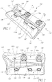
- Figure 3A is a top view of the first portion 116 of the lacing system 114, shown separated from the brace 100.
- Figure 3B is a top view of the second portion 118 of the lacing system 114, also shown separated from the brace 100.
- the first and second housing pieces 136, 138 can include stitch flanges 140, 142 or areas configured to receive stitching to secure the first and second housing pieces 136, 138 to the brace 100. Alternatively, these flanges could be used for adhesive application, RF welding, or insert molding into the main body 102.
- a stitch line 144 can pass through the upper layer 146 of the brace 100, through the stitch flange 142, and through an underlying layer 148. In some embodiments, the upper layer 146 covers only a part of the brace, leaving part of the underlying layer 148 exposed and visible.
- the underlying material 148 can include neoprene, or any other suitable materials.
- the underlying material 148 can be a multilayer material. Additional stitch lines 150a-c can be used to secure the first housing piece 136 to the brace 100. In some embodiments, a single stitch line can be used for securing the first housing piece to the brace 100 between the upper layer 146 and the underlying layer 148.
- the upper layer 146 can include holes therein that correspond to the lace stop 120, first reel 122, second reel 124, and the lace guides 126, 128, 130 such that these components of the lacing system can be positioned on the exterior of the brace 100 while the interconnecting housing pieces 136, 138 can be positioned under the upper layer 146, hidden from view.
- Joining the lace stop 120, the first reel 122, and the second reel 124 onto a single interconnected housing piece 136 provides the benefit that the brace 100 can be produced more quickly, more reliably, and at less cost. It can be less time consuming and cheaper to mold one housing piece than three separate pieces. During assembly, it can be simpler to properly position a single housing piece to be secured (e.g., by stitching) to the brace 100 than to properly position thee separate pieces. Thus, the occurrence of erroneously positioned pieces can be reduced.
- a single stitch line (e.g., 144) can be used instead of multiple stitch lines when multiple components are joined into a single housing piece, further streamlining the assembly process.
- the interconnection of the components may also serve as a therapeutic stiffener for fixation and may be tailored in thickness to achieve a desired stiffness distribution and contour for the desired therapeutic affect.
- the lace stop 120 can be formed as an integral piece with the first housing piece 136.
- the lace stop 120 can be a generally wedge-shaped structure 152 with a hole 154 formed therethrough.
- the end of the first lace 132 can be fed through the hole 154 and a knot can be tied or a fitting may be crimped at the end of the first lace 132, thereby preventing the lace 132 from being pulled back through the hole 154.
- the first housing piece 136 can include a first reel housing 156 and a second reel housing 158 as integral pieces thereof, or as separate pieces attached thereto.
- the reel housings 156, 158 can be configured to receive corresponding spool members 160, 162 therein.
- Knobs 164, 166 can engage the spool member 160, 162, and can be secured to the corresponding reel housings 156, 158 by center screws 168, 170.
- the reels 122, 124 can be configured to incrementally tighten when the knobs 164, 166 are rotated in a tightening direction and to incrementally loosen when the knobs 164, 166 are rotated in a loosening direction. Additional details regarding the reels 122, 124 are disclosed in U.S.
- Figure 5 is a close-up perspective view of the reel housing 156.
- the end of the first lace 132 can enter into the reel housing 156 through the hole 172.
- the hole 172 can be an elongate slot type hole such that the lace 132 can enter the hole 172 from a range of directions without being forced to turn a sharp corner by the walls of the hole 172.
- the first lace 132 can be attached to the spool member 160 such that when the spool member 160 and knob 164 rotate, the lace 132 is either pulled into the reel housing 156 or driven out of the reel housing 156 via the hole 172.
- the end of the second lace 134 can be secured to the reel housing 156 via the hole 174.
- the lace 134 can be inserted through the hole 174 and a knot can be tied or a fitting may be crimped to the end of the lace 134 such that the lace cannot be pulled back through the hole 174.
- the second lace 134 merely uses the first reel 122 as a lace stop, and is not drawn into the reel housing 156 when the reel 122 is tightened.
- Figure 6 is a close-up perspective view of the reel housing 158.
- the end of the second lace 134 can enter into the reel housing 158 through the hole 176.
- the hole 176 can be an elongate slot type hole such that the lace 134 can enter the hole 176 from a range of directions without being forced to turn a sharp corner by the walls of the hole 176.
- the second lace 134 can be attached to the spool member 162 such that when the spool member 162 and knob 166 rotate, the lace 134 is either pulled into the reel housing 158 or driven out of the reel housing 158 via the hole 176.
- the lace 134 can enter the side of the reel 124 that is furthest toward the back of the brace 100 so that the when the reel 124 is tightened, the back end of the brace 100 can be made to fit sufficiently firm on the wearer's arm.
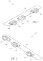
- Figure 7 is a perspective view of the second portion 118 of the lacing system 114.
- Figure 8 is another perspective view of the second portion 118 of the lacing system 114.
- the lace guides 126, 128, 130 can be integrally formed as part of the second housing piece 138.
- the lace guides 126, 128, 130 can be separately formed and attached to the second housing piece 138 by a fastener or an adhesive or any suitable manner of attachment.
- the lace guides 126, 128, 130 can be closed back lace guides, although open back lace guides may also be used.
- the lace guides 126, 128, 130 can be specially positioned on the second housing piece 138 at locations that correspond to the lace path associated with the reels 122, 124 and the lace stop 120.
- the sides of the lace guides 126, 128, 130 can be configured according to the anticipated lace path through the lace guides 126, 128, 130.
- the lace guide 126 has a first curved exit path 178 on a first side to receive the lace coming from the lace stop 120, and a second curved exit path 180 on the other side to receive lace coming from the reel 122.
- the lace guide 128 can have a curved exit path 182 on a first side to receive lace from the reel 122, and a hole 184 that points generally toward the lace guide 130 to direct the lace toward the lace guide 130.
- the lace guide 130 can have a hole 186 than can align collinearly with the hole 184 to receive the lace from the guide 128, and a curved exit path 188 on the opposite side of the hole 186.
- the curved exit paths 178, 180, 182, and 188 and the holes 184, 186 can provide a lace path that includes no corners of less than about a 3 mm radius, or no corners of less than about a 7 mm radius, or no corners of less than about a 10 mm radius, although curvatures outside of these ranges are also possible.
- a single lace guide can be used in place of the two lace guides 128 and 130.
- the single lace guide that replaces the guides 128 and 130 would need to be about three times the length of the lace guides shown in the illustrated embodiment.
- the components of the lacing system 114 are merely examples, and components can be rearranged or omitted and additional components can be added.
- loops of webbing could be preassembled to the interconnection flange 138 to provide a soft and low profile guiding element for the lace. This preassembly could be via rivets, stitching, insert molding or other fastening means.
- the first housing piece 136 and/or the second housing piece 138 can provide support or structure to the brace 100.
- a substantially rigid or semi-rigid material can be used for the housing piece 136 and/or 138.
- a hardness in the range of about 40 Shore D to about 85 Shore D would provide this range of stiffness although other hardnesses may be used.
- the first housing piece 136 and/or the second housing piece 138 can be used in conjunction with a conventional support member (e.g., positioned under the wrist on a wrist brace) or in place of the conventional support member to restrict movement of the wearer's arm.
- the conventional support member commonly used in wrist braces can be omitted from the brace 100 and the first housing piece 136 and/or the second housing piece 138 can provide the rigid support to the brace 100.
- the first housing piece 136 and/or the second housing piece 138 can be positioned on the underside of the wrist, generally opposite of their positions in the illustrated embodiment.
- a somewhat flexible and resilient material can be used to form the housing piece 136 and/or 138 to thereby provide structure to the brace 100 without rigidly restricting movement thereof.
- the first housing piece 136 and/or the second housing piece 138 can be flexible enough to allow the user to bend the portion(s) of the brace 100 that houses the first housing piece 136 and/or the second housing piece 138, but the resilient nature of the material can cause the brace 100 to return to substantially its original position once bending force is released. This stiffness may be controlled via both thickness and hardness. Thicknesses from about 0.7 mm to about 4.0 mm and hardnesses in the range of about 20 Shore D to about 85 Shore D may be employed
- the housing piece 136 can be made from a single material and can be formed as a single unitary piece.
- the housing piece 138 can likewise be made from a single material and can be formed as a single unitary piece.
- different portions of the housing pieces 136, 138 can be made from different material having different levels of hardness, or other differences in properties.
- the stitch flange 142 can be made from a first material, and the lace guides 126, 128, 130 can be made from a different material, for example, by overmolding the guides 126, 128, 130 onto the stitch flange 142.
- the stitch flange 142 can be made from a harder, more rigid material than the lace guides 126, 128, 130.
- the stitch flange 142 can be rigid so as to provide support to the brace 100, and in some cases it can be advantageous to form the lace guides 126, 128, 130 from a material that is softer than the outer material of the lace so that friction between the guides and the lace will tend to wear the guides 126, 128, 130 rather than the outer surface of the lace.
- the stitch flange 142 can be made from a material that is softer than the lace guides 126, 128, 130, such as when the stitch flange 142 is configured to be somewhat flexible to allow movement of the brace 100, and/or when the lace guides 126, 128, 130 are formed from a relatively hard material to prevent wearing of the lace guides during use.
- the housing piece 136 can similarly be made from multiple materials having different properties, such as hardness.
- the lace stop 120, the first reel housing 156, and/or the second reel housing 158 can be made of a material that is either harder or softer than the material used to form the stitch flange 140.
- FIG 9 is a perspective view of an embodiment of an ankle brace 900.
- Figure 10 is another perspective view of the ankle brace 900.
- the ankle brace 900 can be symmetrical for use on either the right or left foot, or it can be specifically designed for use on either the left or right foot. It will be understood that many of the feature and principles discussed in connection with the ankle brace 900 can also be applied to other braces, for example the wrist brace discussed above, or even to other articles such as, but not limited to, hats, gloves, boots, shoes, etc.
- the brace 900 can have a main body 902 that can be generally cylindrical and shaped to receive a foot of a wearer.
- the main body 902 can have a main opening 904 that allows the user's foot to enter the main body 902, and a toes hole 906, and a heel hole 908.
- the main body 902 can have edges 910a-b separated by a space that can increase or decrease depending on the size of the wearer's foot and to allow the wearer to put the brace 900 on and to remove the brace 900.
- a tongue 912 can be positioned between and under the edges 910a-b, and can have a series of tongue guides 913 through which the laces 932, 934 pass to secure the tongue 912 to the main body 902 of the brace 900.
- the tongue guides 913 can be positioned along a single integrated tongue strip 915 which can be positioned, for example, down the center of the tongue 912.
- the brace 900 can include a rigid support member configured to maintain the wearer's foot in the design orientation with relatively little freedom of movement in the wearer's ankle.
- the brace 900 can include a lacing system 914 configured to draw the edges 910a-b towards each other to tighten the brace 900 around the foot of the wearer.
- the lacing system 914 can include various components, some of which are shown in the illustrated embodiment, but it will be understood that aspects of the example illustrated lacing system 914 can be altered, omitted, or added to in other embodiments.
- the lacing system 914 can include an upper portion 916 configured to use a first lace 932 to tighten an upper portion of the brace 900 around the portion of the user's foot above the heel.
- the lacing system 914 can include a lower portion 918 configured to use a second lace 934 to tighten a lower portion of the brace 900 around the portion of the user's foot below the heel.
- the lacing system 914 can include a first reel 922 configured to gather the first lace 932 therein to tighten the upper portion 916 of the lacing system.
- the lacing system 914 can also include a second reel 924 configured to gather the second lace 934 therein to tighten the lower portion 918 of the lacing system 914.
- Figure 10 shows in dotted lines one possible embodiment of lace paths that lead the laces 932, 934 to the reels 922, 924.
- the two reels 922, 924 can both be mounted onto a single housing piece 936.
- Figure 11 is a perspective view of the housing piece 936 and the two reels 922, 924 mounted thereto.
- FIG 12 is another perspective view of the housing piece 936 and reels 922, 924 showing the back side of the housing piece 936.
- the housing piece 936 can be substantially rigid or semi-rigid and can provide structure or support to the back of the brace 900.
- the rigid housing piece 936 can be used in place of a conventional support member to aid in keeping the wearer's foot in a relatively stable position with little freedom of motion in the user's ankle.
- This housing piece 936 could also be provisioned with a flange around its periphery to increase the level of support as desired. Positioning multiple reels on a single housing allows greater control of the reels relative to each other and can reduce error and cost during manufacturing.
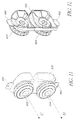
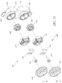
- FIG 13 is an exploded perspective view of the housing piece 936 and reels 922, 924.
- the housing piece 936 can include an upper reel housing 956 configured to receive a first spool member 960 therein.
- a first knob 964 can engage the first spool member 960 and rotatably secure to the first reel housing 956.
- the first knob 964 can include a knob core 963, a knob spring 965, a knob bushing 967, and a knob cover 969.
- the housing piece 936 can also include a lower reel housing 958 configured to receive a second spool member 962 therein.
- a second knob 966 can engage the second spool member 962 and rotatably secure to the second reel housing 958.
- the second knob 966 can include a knob core 971, a knob spring 973, a knob bushing 975, and a knob cover 977. Additional details regarding the components and functionality of the reels 922, 924 of the illustrated embodiment are disclosed in the '013 Application (at least at Figures 38A-46). It will be understood that various other types of reel or lace tightening mechanisms can be used in place of one or both the reel designs 922, 924 shown in the illustrated embodiment.
- the brace 900 can be configured to be worn with a shoe over the top thereof. If the reels 922, 924 were placed too low, or too far apart so that they took up too much space on the back of the brace 900, the lower reel 924 could interfere with the shoe being worn over the top of the brace 900.
- the housing piece 936 forms an integrated, generally elongate, vertically oriented, rigid support on the back portion of the brace 900, the housing piece 936 provides better support to the brace 900 than would two housing pieces that each house one of the reels 922, 924.
- the housing piece 936 can have a top stitch flange 940 and a bottom stitch flange 942 which can receive stitching 944, as shown in Figure 10 to secure the housing piece 936 between an upper layer 946 and an underlying layer 948 of the brace 900.
- this stitch flange may be present around any portion of the periphery.
- a portion of the rigid housing piece 936 can be disposed under the upper layer 946 so as to be hidden from view.
- the reel housings 956, 958 can extend through holes formed in the upper layer 946 such that the reels 922, 924 can be mounted onto the external surface of the brace 100 where they can be visible and exposed.
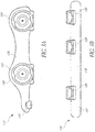
- Figure 14 is a side view of the housing piece 936 and the reels 922, 924.
- the knobs 964, 966 can be toggled between an engaged position and a disengaged position. By pulling one of the knobs 964, 966 away from the housing piece 936 (in the direction of the arrow A), the knob 964, 966 can be disengaged such that the spool member 960, 962 is permitted to spin freely. Thus, when disengaged, the lace can be withdrawn from the reels 922, 924 such that the reels 922, 924 can be loosened. By pushing one of the knobs 964, 966 toward the housing piece 936, the knob 964, 966 can be toggled to the engaged position where the knob can only turn in the tightening direction to draw lace into the reels 922, 924.
- Figure 15 is a bottom view of the housing piece 936 and the reel 924.
- the back surface 911 of the housing piece 936 can be curved to conform to the curvature of brace 900 or approximate the curvature of the wearer's foot that is positioned nearest the back surface 911 of the housing piece 936.
- a first end of the lace 934 can enter the housing piece 936 via a hole 972, and a second end of the lace 934 can enter the housing piece 936 via the hole 974.
- the ends of the lace 934 can attach to the second spool member 962 such that when the reel 924 is rotated about a second axis D in the tightening direction the lace 934 is drawn into the reel 924 to tighten the lower portion 918 of the lace system 914.
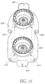
- Figure 16 is another perspective view of the housing member 936 that shows additional holes 976, 978 which can allow the ends of the lace 932 to enter the housing piece 936.
- the ends of the lace 932 can connect to the first spool member 960 such that when the reel 922 is rotated about a first axis C in the tightening direction, the lace 932 is drawn through the holes 176, 178 and into the reel 922 to tighten the upper portion 916 of the lacing system 914.
- the axis C is substantially parallel to the axis D, which in some cases can allow the user to rotate both reels 922, 924 with generally the same hand motion without significant reorientation of the brace 900.
- the axis C about which the first reel 922 rotates is not substantially parallel to the axis D about which the second reel 924 rotates.
- the reels 922, 924 can be located on opposite sides of the brace 900.
- the housing piece 936 can be made from a single material and can be a single unitary piece. In some embodiments, the housing piece 936 can be made from multiple materials that can have different properties, such as different levels of hardness.
- the main body 939 of the housing piece 396 can be made from a first material.
- the stitch flanges 940, 942 can be made from a second material, for example by overmolding, and can have a lower hardness than the first material such that the main body 939 can provide rigid support to the brace 900 while the stitch flanges 940, 942 can be soft enough to be punctured during the stitching process.
- the main body 939 can be softer than the stitch flanges 940, 942 such that the body can be somewhat flexible to allow some degree of movement in the brace 900 while the stitch flanges 940, 942 can be harder to prevent them from being ripped from the stitching by the force of the tightened lacing system 914.
- the reel housings 957, 958 can also be made from a different material than the main body 939 or than the stitch flanges 940, 942.
- the brace 100 can include several lace guides configured to provide lace paths for the laces 932, 934. Some of the lace guides can be closed back lace guides 926 which can prevent the lace from disengaging from the lace guides 926. In some embodiments, one or more of the lace guides can be a backless lace guide 928 (e.g., one of the lace guides of the upper portion 916 of the lace system). The lace 932 can be pulled out of the back of the backless lace guide 928 such that the lace 932 completely disengages from the backless lace guide 928.
- a backless lace guide 928 e.g., one of the lace guides of the upper portion 916 of the lace system
- the extra length of lace 932 that was previously engaged with the backless lace guide 928 can provide significant slack to the upper portion 916 of the lace system 914, thereby allowing the brace 900 to open wider to accommodate the insertion of the wearer's foot therein.
- the lace 932 can be pulled back onto the backless lace guide 928 to take up the slack previously introduced. This allows the tightener (e.g., one or both of the reels 922, 924) to be smaller in that the lace length necessary to provide slack for inserting and removing the wearer's foot need not be stored inside the tightener.
- one or more of the lace guides can direct the lace 932, 934 to the corresponding reels 922, 924.
- the top two reel-leading lace guides 930a-b can lead the ends of the lace 932 to the upper reef 922 via tubing inserted into the lace guides 930a-b at the first end and inserted into the housing piece 936 at the second end, and the lower two reel-leading lace guides 930c-d can lead the ends of the lace 934, also via tubing, to the lower reel 924.
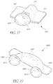
- Figure 17 shows a perspective view of one of the reel-leading lace guides 930a-d.
- the reel-leading lace guide 930 can have a lace channel portion 931 that can be disposed below the upper layer 946 of the brace 900 such that the lace channel portion 931 is hidden from view during normal use.
- the lace channel 931 can be longer than as shown in the illustrated embodiment and can lead to one of the reels 922, 924.
- the lace channel 931 can lead to a supplemental channel, for example a polymer tube (not shown), that leads to the reels 922, 924.
- An end piece 933 can be positioned at least partially on the outside of the upper layer 946 such that the end piece 933 is exposed and visible.
- the end piece can have a nonuniform flange 935 around the opening to the lace channel that extends further at the bottom than at the top.
- the flange 935 can be generally bell-shaped.
- the end piece can provide a curved sliding surface for the lace 932, 934 to side against as it passes in or out of the lace channel.
- One or more stitch flanges 937 can be used to secure the lace guide 930 to the brace 900 with stitching, although other attachment methods can be used.
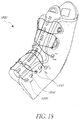
- Figure 18 is a perspective view of an ankle brace 1800 that can be similar to, or the same as, the ankle brace 900 discussed herein.
- the brace 1800 can have included low profile lace guides 1850 that can be similar in some regards to the lace guides 930 discussed above.
- the lower profile lace guides can facilitate the use of the brace 1800 with a shoe worn over the top thereof.
- each of the lace guides of the lower portion 1818 of the lace system 1814 can be low profile lace guides 1850.
- Figure 19 is a perspective view of a lower profile lace guide 1850 that includes a lace channel 1802 that can be disposed below an upper layer 1846 of the brace 1800 when assembled (as shown in Figure 18 ).
- the lace guide 1850 can have a generally U-shaped lace channel 1852 with the lace passing from a first opening 1804 to a second opening 1806.
- the lace guide 1850 can include an end piece 1810 at each opening.
- the end piece 1810 can be similar to, or the same as the end piece 933 discussed above.
- a stitch flange 1852 can be used to stitch the lace guide 1850 to the brace 1800.
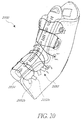
- Figure 20 is a perspective view of another embodiment of an ankle brace 2000 having low profile lace guides 2050.
- one or more of the low profile lace guides 2050 can include a pair of angled loops 2052a, 2052b of, for instance, a woven polymer webbing, similar to the lace guides described in U.S. Patent Application No. 13/011,707 (the "'707 Application"), filed January 21, 2011, and titled “GUIDES FOR LACING SYSTEMS," the entirety of which is hereby incorporated by reference herein and made a part of this specification for all that it discloses.
- the lace 2034 can pass through two consecutive loops on one side before being directed to the opposite side, as described in greater detail in the '707 Application.
- low profile lace guides can be used, such as, for example, those disclosed in connection with Figures 1-2B of the '707 Application.
- the illustrated embodiment of Figure 20 shows certain lace guides located on the lower portion of the brace 2000 having low profile lace guides 2050 (e.g., the angled loop pairs 2052a, 2052b), which can allow a shoe to be worn over the top of the brace 2000.
- low profile laces such as angled loop pairs similar to 2052a and 2052b can be used for the other lace guides on the brace 2000.
- all the lace guides on the brace 2000 can be low profile lace guides.
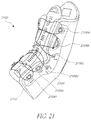
- Figure 21 is a perspective view of another embodiment of an ankle brace 2100 in which multiple lace guides are incorporated into a single housing piece.
- the single housing piece 2102 is shown in dotted lines in Figure 21 because it is hidden from view below the upper layer 2104 of the brace 2100.
- all six of the lace guides 2106a-f on the left side of the brace 2100 are incorporated into the single housing piece 2102, although in some embodiments a different number of lace guides 2106 can be incorporated into a single housing, and in some cases multiple housings can be used each incorporating multiple lace guides.
- lace guides 2106a-c can be incorporated into one housing and the lace guides 2106d-f can be incorporated into a different housing. Many variations are possible.
- Joining multiple lace guides by a single housing piece can provide benefits similar to those discussed above in connection with the wrist brace 100. For example, the cost to manufacture the lace guides can be reduced if less pieces are required. Also, assembly of the brace 2100 can be simplified and the occurrence of erroneously positioned pieces can be reduced. Additionally, the housing piece can provide additional support and structure to the brace 2100 along with appropriate points of flexure.
Applications Claiming Priority (2)
| Application Number | Priority Date | Filing Date | Title |
|---|---|---|---|
| US36061910P | 2010-07-01 | 2010-07-01 | |
| EP11801455.4A EP2588044B1 (fr) | 2010-07-01 | 2011-06-30 | Attaches utilisant des systèmes de laçage |
Related Parent Applications (2)
| Application Number | Title | Priority Date | Filing Date |
|---|---|---|---|
| EP11801455.4A Division EP2588044B1 (fr) | 2010-07-01 | 2011-06-30 | Attaches utilisant des systèmes de laçage |
| EP11801455.4A Division-Into EP2588044B1 (fr) | 2010-07-01 | 2011-06-30 | Attaches utilisant des systèmes de laçage |
Publications (1)
| Publication Number | Publication Date |
|---|---|
| EP3061427A1 true EP3061427A1 (fr) | 2016-08-31 |
Family
ID=45400247
Family Applications (2)
| Application Number | Title | Priority Date | Filing Date |
|---|---|---|---|
| EP16157943.8A Withdrawn EP3061427A1 (fr) | 2010-07-01 | 2011-06-30 | Entretoises utilisant des systèmes de laçage |
| EP11801455.4A Not-in-force EP2588044B1 (fr) | 2010-07-01 | 2011-06-30 | Attaches utilisant des systèmes de laçage |
Family Applications After (1)
| Application Number | Title | Priority Date | Filing Date |
|---|---|---|---|
| EP11801455.4A Not-in-force EP2588044B1 (fr) | 2010-07-01 | 2011-06-30 | Attaches utilisant des systèmes de laçage |
Country Status (7)
| Country | Link |
|---|---|
| US (1) | US9918865B2 (fr) |
| EP (2) | EP3061427A1 (fr) |
| JP (2) | JP6027530B2 (fr) |
| CN (1) | CN103228235B (fr) |
| AU (1) | AU2011272791B2 (fr) |
| CA (1) | CA2804759C (fr) |
| WO (1) | WO2012003396A2 (fr) |
Cited By (2)
| Publication number | Priority date | Publication date | Assignee | Title |
|---|---|---|---|---|
| CN107205501A (zh) * | 2014-11-10 | 2017-09-26 | 耐克创新有限合伙公司 | 前臂和手腕支撑袖子 |
| IT202000004831A1 (it) * | 2020-03-06 | 2021-09-06 | Casilla Franklin Julio Cesar Romero | Fascia di sovraccarico e kit di sovraccarico comprendente la stessa |
Families Citing this family (123)
| Publication number | Priority date | Publication date | Assignee | Title |
|---|---|---|---|---|
| US20060156517A1 (en) | 1997-08-22 | 2006-07-20 | Hammerslag Gary R | Reel based closure system |
| EP2789251A1 (fr) | 2004-10-29 | 2014-10-15 | Boa Technology, Inc. | Mécanisme de serrage utilisable avec un système de laçage d'une chaussure |
| PT1981459E (pt) | 2006-01-13 | 2011-12-21 | Convatec Technologies Inc | Dispositivo, sistema e método para tratamento por compressão de uma parte do corpo |
| WO2008033963A2 (fr) | 2006-09-12 | 2008-03-20 | Boa Technology, Inc. | Système de fermeture pour bretelles, vêtements de protection et articles similaires |
| CN101977525B (zh) | 2008-01-18 | 2012-12-12 | 博技术有限公司 | 用于物件的收紧系统和用于将两个物体彼此拉近或拉开的方法 |
| WO2010059989A2 (fr) | 2008-11-21 | 2010-05-27 | Boa Technology, Inc. | Système de tendeur basé sur un dévidoir |
| KR101865761B1 (ko) | 2010-01-21 | 2018-06-08 | 보아 테크놀러지, 인크. | 끈 조임 시스템용 가이드들 |
| US10070695B2 (en) | 2010-04-30 | 2018-09-11 | Boa Technology Inc. | Tightening mechanisms and applications including the same |
| KR101875508B1 (ko) | 2010-04-30 | 2018-07-06 | 보아 테크놀러지, 인크. | 릴 기반 끈 조임 시스템 |
| US9375053B2 (en) | 2012-03-15 | 2016-06-28 | Boa Technology, Inc. | Tightening mechanisms and applications including the same |
| US10166150B2 (en) * | 2011-07-28 | 2019-01-01 | Norton Salas Group, Inc. | Therapeutic compression device and method |
| US10786397B2 (en) * | 2011-07-28 | 2020-09-29 | Norton Salas Group, Inc. | Therapeutic compression device and method |
| US9101181B2 (en) | 2011-10-13 | 2015-08-11 | Boa Technology Inc. | Reel-based lacing system |
| US11071344B2 (en) | 2012-02-22 | 2021-07-27 | Nike, Inc. | Motorized shoe with gesture control |
| US11684111B2 (en) | 2012-02-22 | 2023-06-27 | Nike, Inc. | Motorized shoe with gesture control |
| US9144168B2 (en) | 2012-03-08 | 2015-09-22 | The United States Of America, As Represented By The Secretary Of The Air Force | Appendage-mounted display apparatus |
| US9179729B2 (en) | 2012-03-13 | 2015-11-10 | Boa Technology, Inc. | Tightening systems |
| DE102012009214A1 (de) | 2012-05-02 | 2013-11-07 | Bauerfeind Ag | Spannvorrichtung für Orthesen |
| DE102012011742A1 (de) * | 2012-06-08 | 2013-12-12 | Bauerfeind Ag | Spannvorrichtung für Orthesen |
| US10327977B2 (en) | 2012-06-18 | 2019-06-25 | 3M Innovative Properties Company | Dual density pressure pad |
| EP2871994B8 (fr) | 2012-08-31 | 2020-11-04 | NIKE Innovate C.V. | Système de tension motorisé à capteurs |
| EP2871991B1 (fr) | 2012-08-31 | 2018-11-28 | NIKE Innovate C.V. | Système motorisé de mise en tension |
| US10688007B2 (en) | 2012-09-14 | 2020-06-23 | Recovery Force, LLC | Compression device |
| US10918561B2 (en) * | 2012-09-14 | 2021-02-16 | Recovery Force, LLC | Compression device |
| US9516923B2 (en) | 2012-11-02 | 2016-12-13 | Boa Technology Inc. | Coupling members for closure devices and systems |
| EP2916680B1 (fr) * | 2012-11-06 | 2018-12-26 | Boa Technology Inc. | Dispositifs et procédés de réglage de l'ajustement de chaussures |
| KR101249420B1 (ko) * | 2012-12-17 | 2013-04-03 | 주식회사 신경 | 와이어 조임장치 |
| WO2014117184A1 (fr) | 2013-01-28 | 2014-07-31 | Boa Technology Inc. | Ensemble et système de fixation de lacet |
| US9153215B2 (en) | 2013-01-31 | 2015-10-06 | Final Frontier Technology, Llc | Mouthpiece ligature for woodwind instruments |
| WO2014124054A1 (fr) * | 2013-02-05 | 2014-08-14 | Boa Technology Inc. | Dispositifs de fermeture pour dispositifs médicaux et procédés |
| US10251451B2 (en) | 2013-03-05 | 2019-04-09 | Boa Technology Inc. | Closure devices including incremental release mechanisms and methods therefor |
| WO2014138297A1 (fr) | 2013-03-05 | 2014-09-12 | Boa Technology Inc. | Systèmes, procédés et dispositifs de fermeture automatique de dispositifs médicaux |
| US9706814B2 (en) | 2013-07-10 | 2017-07-18 | Boa Technology Inc. | Closure devices including incremental release mechanisms and methods therefor |
| US20140276318A1 (en) * | 2013-03-12 | 2014-09-18 | Footmind, Inc. | Orthotic device, system and methods for addressing foot drop |
| US20140276320A1 (en) * | 2013-03-12 | 2014-09-18 | Footmind, Inc. | Orthosis, system and methods for addressing foot drop |
| US9357807B2 (en) | 2013-03-15 | 2016-06-07 | Under Armour, Inc. | Size adjustment arrangement for a garment |
| GB201305545D0 (en) | 2013-03-27 | 2013-05-08 | 3M Innovative Properties Co | Compression device |
| US9532626B2 (en) | 2013-04-01 | 2017-01-03 | Boa Technology, Inc. | Methods and devices for retrofitting footwear to include a reel based closure system |
| US10076160B2 (en) | 2013-06-05 | 2018-09-18 | Boa Technology Inc. | Integrated closure device components and methods |
| EP3777595A1 (fr) * | 2013-06-05 | 2021-02-17 | Boa Technology Inc. | Éléments d'un dispositif de fermeture intégré, et procédés |
| US9474330B2 (en) | 2013-06-10 | 2016-10-25 | Nike, Inc. | Article with adjustable rearward covering portion |
| JP6087219B2 (ja) | 2013-06-18 | 2017-03-01 | 株式会社ジャパーナ | 靴紐巻取装置 |
| JP6105404B2 (ja) * | 2013-06-18 | 2017-03-29 | 株式会社ジャパーナ | 靴紐巻取用リール |
| US9629417B2 (en) * | 2013-07-02 | 2017-04-25 | Boa Technology Inc. | Tension limiting mechanisms for closure devices and methods therefor |
| US10645990B2 (en) | 2013-08-19 | 2020-05-12 | Nike, Inc. | Article of footwear with adjustable sole |
| US9491983B2 (en) * | 2013-08-19 | 2016-11-15 | Nike, Inc. | Article of footwear with adjustable sole |
| US9700101B2 (en) | 2013-09-05 | 2017-07-11 | Boa Technology Inc. | Guides and components for closure systems and methods therefor |
| KR102297325B1 (ko) | 2013-09-13 | 2021-09-03 | 보아 테크놀러지, 인크. | 릴 기반 폐쇄 장치 및 그에 따른 방법 |
| EP3071159A1 (fr) | 2013-11-18 | 2016-09-28 | Boa Technology, Inc. | Procédés et dispositifs permettant une fermeture automatique de prothèses et d'orthèses |
| ITVR20130295A1 (it) * | 2013-12-23 | 2015-06-24 | Selle Royal Spa | Calzatura sportiva |
| ITVR20130294A1 (it) | 2013-12-23 | 2015-06-24 | Selle Royal Spa | Calzatura sportiva |
| USD835976S1 (en) | 2014-01-16 | 2018-12-18 | Boa Technology Inc. | Coupling member |
| US9414949B2 (en) | 2014-03-06 | 2016-08-16 | Tyrone Wilson | Shoe interfaced ankle support apparatus |
| US9364054B2 (en) * | 2014-04-09 | 2016-06-14 | Tristan S. Gittens | Accessory cinching device |
| US9326566B2 (en) | 2014-04-15 | 2016-05-03 | Nike, Inc. | Footwear having coverable motorized adjustment system |
| US9629418B2 (en) | 2014-04-15 | 2017-04-25 | Nike, Inc. | Footwear having motorized adjustment system and elastic upper |
| US10092065B2 (en) | 2014-04-15 | 2018-10-09 | Nike, Inc. | Footwear having motorized adjustment system and removable midsole |
| US9908027B2 (en) * | 2014-04-22 | 2018-03-06 | Nike, Inc. | Article of apparel with dynamic padding system |
| US10492974B2 (en) * | 2014-06-23 | 2019-12-03 | Tactile Systems Technology, Inc. | Compression garment system with tightening apparatus |
| KR101538642B1 (ko) * | 2014-06-26 | 2015-07-22 | 주식회사 우리소재 | 변형성과 강성이 우수한 열가소성 캐스트 및 그 제조방법 |
| USD751281S1 (en) * | 2014-08-12 | 2016-03-15 | Boa Technology, Inc. | Footwear tightening reels |
| USD767269S1 (en) | 2014-08-26 | 2016-09-27 | Boa Technology Inc. | Footwear tightening reel |
| US20160058127A1 (en) | 2014-08-28 | 2016-03-03 | Boa Technology Inc. | Devices and methods for enhancing the fit of boots and other footwear |
| USD758061S1 (en) | 2014-09-08 | 2016-06-07 | Boa Technology, Inc. | Lace tightening device |
| WO2016054317A1 (fr) | 2014-10-01 | 2016-04-07 | Ossur Hf | Support pour articles et procédés pour les utiliser |
| US10575591B2 (en) | 2014-10-07 | 2020-03-03 | Boa Technology Inc. | Devices, methods, and systems for remote control of a motorized closure system |
| WO2016109258A1 (fr) * | 2014-12-30 | 2016-07-07 | 3M Innovative Properties Company | Attelle polymère imperméable à l'eau |
| USD835898S1 (en) | 2015-01-16 | 2018-12-18 | Boa Technology Inc. | Footwear lace tightening reel stabilizer |
| USD776421S1 (en) | 2015-01-16 | 2017-01-17 | Boa Technology, Inc. | In-footwear lace tightening reel |
| CN106473893A (zh) * | 2015-08-26 | 2017-03-08 | 黄石钊 | 肘关节肢体牵拉装置 |
| CN108366880A (zh) | 2015-10-05 | 2018-08-03 | 泰科蒂尔系统科技公司 | 可调节加压服装 |
| JP6968804B2 (ja) | 2015-10-05 | 2021-11-17 | タクティル システムズ テクノロジー,インコーポレイティド | 頭部と首の圧迫治療システム |
| US11103030B2 (en) | 2015-10-07 | 2021-08-31 | Puma SE | Article of footwear having an automatic lacing system |
| US11033079B2 (en) | 2015-10-07 | 2021-06-15 | Puma SE | Article of footwear having an automatic lacing system |
| US11185130B2 (en) | 2015-10-07 | 2021-11-30 | Puma SE | Article of footwear having an automatic lacing system |
| US10004297B2 (en) | 2015-10-15 | 2018-06-26 | Boa Technology Inc. | Lacing configurations for footwear |
| CN108366647B (zh) * | 2015-10-19 | 2021-06-25 | 耐克创新有限合伙公司 | 用于鞋类鞋带元件的牵索式锚定部 |
| USD788446S1 (en) * | 2015-10-23 | 2017-06-06 | Airtox International A/S | Locking device for shoes |
| WO2017092775A1 (fr) | 2015-12-02 | 2017-06-08 | Puma SE | Procédé pour le laçage d'une chaussure, en particulier d'une chaussure de sport |
| DE102015121123A1 (de) * | 2015-12-04 | 2017-06-08 | Fachhochschule Lübeck | Repositionsvorrichtung |
| CN108697537A (zh) | 2016-01-21 | 2018-10-23 | 泰科蒂尔系统科技公司 | 压缩服装系统 |
| US10827804B2 (en) * | 2016-03-15 | 2020-11-10 | Nike, Inc. | Lacing apparatus for automated footwear platform |
| WO2017189926A1 (fr) | 2016-04-27 | 2017-11-02 | Radial Medical, Inc. | Systèmes et méthodes de compressothérapie adaptative |
| JP2017205301A (ja) * | 2016-05-18 | 2017-11-24 | 株式会社ジャパーナ | 靴紐ガイド |
| ITUA20164251A1 (it) * | 2016-06-09 | 2017-12-09 | Sidi Sport S R L | Calzatura sportiva, in particolare per ciclismo |
| US10499709B2 (en) | 2016-08-02 | 2019-12-10 | Boa Technology Inc. | Tension member guides of a lacing system |
| USD877459S1 (en) | 2016-08-31 | 2020-03-10 | Tactile Systems Technology, Inc. | Torso garment |
| EP3509452B1 (fr) | 2016-09-09 | 2021-07-21 | Djo, Llc | Attelle de cheville |
| GB2556877B (en) | 2016-11-17 | 2022-04-06 | Neo G Ltd | Back brace |
| AU2016430820A1 (en) | 2016-11-22 | 2019-06-13 | Puma SE | A Method of Actuating a Rotary Closure |
| CN110049693A (zh) | 2016-11-22 | 2019-07-23 | 彪马欧洲股份公司 | 紧固鞋(特别是运动鞋)的方法及鞋(特别是运动鞋) |
| KR102494446B1 (ko) | 2016-12-09 | 2023-02-01 | 보아 테크놀러지, 인크. | 릴 기반의 폐쇄 시스템 |
| JP6881993B2 (ja) | 2017-02-01 | 2021-06-02 | 株式会社アルペン | 紐巻取装置を備えた物品 |
| US10543630B2 (en) | 2017-02-27 | 2020-01-28 | Boa Technology Inc. | Reel based closure system employing a friction based tension mechanism |
| US11357279B2 (en) | 2017-05-09 | 2022-06-14 | Boa Technology Inc. | Closure components for a helmet layer and methods for installing same |
| EP3629820B1 (fr) * | 2017-05-31 | 2022-08-31 | NIKE Innovate C.V. | Systèmes de laçage automatique de chaussures |
| USD897661S1 (en) * | 2017-06-07 | 2020-10-06 | Boa Technology Inc. | Lace tightening device |
| US10772384B2 (en) | 2017-07-18 | 2020-09-15 | Boa Technology Inc. | System and methods for minimizing dynamic lace movement |
| USD848625S1 (en) | 2017-09-28 | 2019-05-14 | Tactile Systems Technology, Inc. | Leg garment |
| USD849254S1 (en) | 2017-09-28 | 2019-05-21 | Tactile Systems Technology, Inc. | Combination trunk and leg garment |
| USD870297S1 (en) | 2017-09-28 | 2019-12-17 | Tactile Systems Technology, Inc. | Trunk garment |
| EP4079270A1 (fr) | 2017-11-06 | 2022-10-26 | Tactile Systems Technology, Inc. | Systèmes de vêtement de compression |
| CN209661633U (zh) * | 2018-04-12 | 2019-11-22 | 均威科技(深圳)有限公司 | 血压计手带 |
| CN108542374A (zh) * | 2018-04-12 | 2018-09-18 | 均威科技(深圳)有限公司 | 血压计手带 |
| USD889805S1 (en) | 2019-01-30 | 2020-07-14 | Puma SE | Shoe |
| USD906657S1 (en) | 2019-01-30 | 2021-01-05 | Puma SE | Shoe tensioning device |
| USD899053S1 (en) | 2019-01-30 | 2020-10-20 | Puma SE | Shoe |
| WO2020181174A1 (fr) * | 2019-03-07 | 2020-09-10 | Ossur Iceland Ehf | Adaptateur pour dispositif rotatif |
| USD880834S1 (en) * | 2019-04-12 | 2020-04-14 | Nike, Inc. | Shoe |
| JP7454267B2 (ja) | 2019-05-01 | 2024-03-22 | ボア テクノロジー,インコーポレイテッド | リール式クロージャーシステム |
| WO2020247645A1 (fr) | 2019-06-05 | 2020-12-10 | Hurley Garrett Ray | Dispositifs de fermeture réglables avec poignée et mécanismes de verrouillage |
| USD884197S1 (en) | 2019-07-12 | 2020-05-12 | Recoup Fitness LLC | Compression sleeve |
| US11484089B2 (en) | 2019-10-21 | 2022-11-01 | Puma SE | Article of footwear having an automatic lacing system with integrated sound damping |
| USD931594S1 (en) * | 2020-03-13 | 2021-09-28 | Nike, Inc. | Shoe |
| US11478032B2 (en) * | 2020-05-06 | 2022-10-25 | LoRonda Brazelton | Pull-release closure apparatus and method |
| US11690748B2 (en) * | 2020-06-18 | 2023-07-04 | Footscientific Inc. | Orthosis brace comprising reel-based lacing system |
| EP3944784A1 (fr) * | 2020-07-31 | 2022-02-02 | Specialized Bicycle Components, Inc. | Système de laçage de chaussure de cyclisme |
| USD938158S1 (en) * | 2020-09-17 | 2021-12-14 | Skechers U.S.A., Inc. Ii | Shoe upper |
| US11974637B2 (en) | 2021-03-01 | 2024-05-07 | Ariat International, Inc. | Boots with fit adjustment systems |
| GB202105008D0 (en) * | 2021-04-08 | 2021-05-26 | Mas Innovation Private Ltd | Compression apparatus |
| US11717076B1 (en) * | 2022-04-26 | 2023-08-08 | Hand Held Products, Inc. | Strap assembly for a wearable mobile device and method of using the same |
| USD1000062S1 (en) * | 2023-05-08 | 2023-10-03 | Jingliang You | Shoe accessory part |
| USD1014765S1 (en) * | 2023-11-16 | 2024-02-13 | Ping Hu | Wrist brace with knob |
Citations (5)
| Publication number | Priority date | Publication date | Assignee | Title |
|---|---|---|---|---|
| WO1994009728A1 (fr) * | 1992-10-23 | 1994-05-11 | Bio Cybernetics International | Attelle electromecanique pour le dos |
| WO1999065428A1 (fr) * | 1998-06-18 | 1999-12-23 | Bio Cybernetics International | Orthese adaptee aux caracteristiques personnelles |
| WO2001060289A1 (fr) * | 2000-02-15 | 2001-08-23 | Royce Medical Company | Dispositifs orthopediques moules |
| US20020068890A1 (en) * | 2000-12-05 | 2002-06-06 | Schwenn Shannon R. | Modular orthosis closure system and method |
| US20050054960A1 (en) * | 2003-09-09 | 2005-03-10 | Telles Jeffrey L. | Orthosis closure system with mechanical advantage |
Family Cites Families (294)
| Publication number | Priority date | Publication date | Assignee | Title |
|---|---|---|---|---|
| US80834A (en) | 1868-08-11 | Improvement in clasp foe boots and shoes, belts foe ladies dresses | ||
| US117530A (en) | 1871-08-01 | Improvement in glove-fasteners | ||
| US59332A (en) | 1866-10-30 | Improvement in clasps for belting | ||
| US230759A (en) | 1880-08-03 | Shoe-clasp | ||
| US228946A (en) | 1880-06-15 | Feiedeich schulz and august schulz | ||
| GB189911673A (en) | 1899-06-05 | 1899-07-22 | Jean Louis Edouard Bourbaud | A New or Improved Appliance for Use in Fastening Boots and Shoes. |
| US746563A (en) | 1903-03-06 | 1903-12-08 | James Mcmahon | Shoe-lacing. |
| US819993A (en) | 1905-05-09 | 1906-05-08 | William E Haws | Lacing. |
| CH41765A (de) | 1907-09-03 | 1908-11-16 | Heinrich Schneider | Klemmvorrichtung für Zugorgane |
| US908704A (en) | 1908-04-02 | 1909-01-05 | Mahlon A Stair | Shoe-fastener. |
| US1170472A (en) | 1909-08-27 | 1916-02-01 | John Wesley Barber | Fastener for shoes, &c. |
| US1083775A (en) | 1911-10-04 | 1914-01-06 | James J Thomas | Shoe-lacer. |
| US1062511A (en) | 1912-06-19 | 1913-05-20 | Henry William Short | Boot-lace. |
| US1060422A (en) | 1912-10-22 | 1913-04-29 | Albertis Bowdish | Device for securing the flaps of boots or shoes. |
| US1090438A (en) | 1913-02-20 | 1914-03-17 | Charles H Worth | Lacing-holder. |
| US1288859A (en) | 1917-11-14 | 1918-12-24 | Albert S Feller | Shoe-lace fastener. |
| US1412486A (en) | 1920-10-06 | 1922-04-11 | Paine George Washington | Lacing device |
| US1416203A (en) | 1921-05-21 | 1922-05-16 | Hobson Orlen | Apparel lacing |
| US1393188A (en) | 1921-05-24 | 1921-10-11 | Whiteman Allen Clay | Lacing device |
| US1469661A (en) | 1922-02-06 | 1923-10-02 | Migita Tosuke | Lacing means for brogues, leggings, and the like |
| US1502919A (en) | 1922-07-10 | 1924-07-29 | Frank A Seib | Shoe |
| US1481903A (en) | 1923-04-09 | 1924-01-29 | Alonzo W Pangborn | Shoe-lacing device |
| GB216400A (en) | 1923-07-10 | 1924-05-29 | Jules Lindauer | An improved yielding connection between pieces of fabric, leather or the like |
| US1530713A (en) | 1924-02-11 | 1925-03-24 | Clark John Stephen Day | Lacing device for boots and shoes |
| CH111341A (de) | 1924-10-02 | 1925-11-02 | Voegeli Eduard | Schnürband-Schuhverschluss. |
| US1862047A (en) | 1930-07-08 | 1932-06-07 | Robert L Boulet | Shoe fastening device |
| DE555211C (de) | 1931-02-24 | 1932-07-20 | Theo Thomalla | Verschluss fuer Schuhe und andere Bekleidungsstuecke |
| US1995243A (en) | 1934-06-12 | 1935-03-19 | Charles J Clarke | Lacing or fastening boots, shoes, or the like |
| CH183109A (de) | 1935-07-03 | 1936-03-15 | Testa Giovanni | Sportschuh mit Vorderschluss, insbesondere als Ski- und Bergschuh geeignet. |
| DE641976C (de) | 1935-09-22 | 1937-02-18 | Otto Keinath | Schuhverschluss |
| US2124310A (en) | 1935-09-25 | 1938-07-19 | Jr Max Murr | Boot |
| US2088851A (en) | 1936-09-16 | 1937-08-03 | John E Gantenbein | Shoe top |
| CH199766A (de) | 1937-08-06 | 1938-09-15 | Ernst Blaser | Schuhverschluss. |
| CH204834A (de) | 1938-08-20 | 1939-05-31 | Romer Hans | Schuh. |
| US2316102A (en) | 1942-05-23 | 1943-04-06 | Frank W Preston | Lacing equipment |
| CH247693A (de) | 1945-11-17 | 1947-03-31 | E Mangold | Schuh, insbesondere für Sportzwecke. |
| US2611940A (en) | 1950-04-20 | 1952-09-30 | Thomas C Cairns | Shoelace tightener |
| US2673381A (en) | 1951-12-13 | 1954-03-30 | Fred E Dueker | Quick lace shoelace tightener |
| DE1661668U (de) | 1953-05-11 | 1953-08-20 | Hans Meiswinkel G M B H | Schnuerverschluss und -verbindung. |
| US2907086A (en) | 1957-02-25 | 1959-10-06 | Lewis R Ord | Hose clamp |
| US2991523A (en) | 1959-02-10 | 1961-07-11 | Conte Robert I Del | Cord storage and length adjusting device |
| US3035319A (en) | 1959-09-15 | 1962-05-22 | Harry O Wolff | Clamp devices |
| DE1190359B (de) | 1960-04-05 | 1965-04-01 | Franz Fesl | Sportschuh, insbesondere Skischuh |
| US3163900A (en) | 1961-01-20 | 1965-01-05 | Martin Hans | Lacing system for footwear, particularly ski-boot fastener |
| CH411623A (de) | 1962-06-14 | 1966-04-15 | Stadler Ferdinand | Verschnürung für Schuhe, insbesondere Sportschuhe (Skischuhe) |
| FR1374110A (fr) | 1962-11-08 | 1964-10-02 | Dispositif pour le serrage du laçage de chaussures | |
| AT246605B (de) | 1963-03-06 | 1966-04-25 | Stocko Metallwarenfab Henkels | Schnürhaken für Schuhe |
| US3112545A (en) | 1963-04-15 | 1963-12-03 | Williams Luther | Shoe fastening device |
| BE650533A (fr) | 1963-07-15 | |||
| AT242560B (de) | 1963-07-18 | 1965-09-27 | Karl Piberhofer | Schnürhaken |
| US3197155A (en) | 1963-09-25 | 1965-07-27 | Rev Andrew Song | Device for tightening shoe laces |
| CH476474A (de) | 1966-07-21 | 1969-08-15 | Martin Hans | Skischuh |
| US3430303A (en) | 1966-08-11 | 1969-03-04 | Donald E Perrin | Lace wind |
| CH471553A (de) | 1967-04-26 | 1969-04-30 | Martin Hans | Skischuh mit Einrichtung zum Zusammenziehen der Schliesslappen |
| US3401437A (en) | 1967-05-10 | 1968-09-17 | Aeroquip Corp | Hose clamp |
| DE1785220A1 (de) | 1968-08-28 | 1971-05-13 | Zimmermann O H | Schuhriemen |
| DE6933746U (de) | 1968-10-05 | 1970-04-09 | Calzaturificio S Marco Tessaro | Schnuervorrichtung, insbesondere fuer skischuhe |
| CA869238A (en) | 1969-02-19 | 1971-04-27 | Shnuriwsky Michael | Sleeved boot |
| US3668791A (en) | 1969-07-08 | 1972-06-13 | Otto Salzman | Fastener for ski boots and the like footwear |
| AT296086B (de) | 1969-10-03 | 1972-01-25 | Josef Graup | Verschluß, insbesondere für Schi- oder Bergschuhe |
| US3703775A (en) | 1970-09-15 | 1972-11-28 | Joseph Gatti | Football boots |
| FR2108429A5 (fr) | 1970-09-23 | 1972-05-19 | Weinmann Ag | |
| DE2046889A1 (de) | 1970-09-23 | 1972-03-30 | Weinmann & Co Kg, 7700 Singen | Schuhverschluß, insbesondere für Skischuhe |
| DE7043154U (de) | 1970-11-23 | 1971-03-18 | Ruesz L | Schnurstiefel |
| DE7045778U (de) | 1970-12-11 | 1971-03-25 | Weinmann & Co Kg | Sportschuhverschluß |
| DE2062795A1 (de) | 1970-12-19 | 1972-06-29 | Weinmann & Co. KG, 7700 Singen | Verschiebbarer Sportschuhverschluss |
| DE7047038U (de) | 1970-12-19 | 1974-01-24 | Weinmann & Co Kg | Verschiebbarer Sportschuhverschluß |
| US3729779A (en) | 1971-06-07 | 1973-05-01 | K Porth | Ski boot buckle |
| GB1370914A (en) | 1971-07-06 | 1974-10-16 | Ici Ltd | Paint compositions |
| FR2173451A5 (fr) | 1972-02-25 | 1973-10-05 | Picard Rene | |
| FR2175684B3 (fr) | 1972-03-15 | 1974-10-31 | Trappeur | |
| CH562015A5 (fr) | 1972-03-21 | 1975-05-30 | Weinmann Ag | |
| DE2317408C2 (de) | 1972-04-17 | 1982-12-23 | Etablissements François Salomon et Fils, 74011 Annecy, Haute-Savoie | Skischuh |
| DE2341658A1 (de) | 1972-08-23 | 1974-03-07 | Polyair Maschb Gmbh | Skischuh |
| DE2414439A1 (de) | 1974-03-26 | 1975-10-16 | Stocko Metallwarenfab Henkels | Verschlussystem fuer schuhe, insbesondere skischuhe |
| AT348896B (de) | 1974-06-20 | 1979-03-12 | Martin Hans | Verschluss fuer skischuhe |
| JPS512776A (ja) | 1974-06-28 | 1976-01-10 | Naniwa Plywood Co Ltd | Enbosutsukiramineetokeshobanno seizoho |
| US3934346A (en) | 1974-12-12 | 1976-01-27 | Kyozo Sasaki | Sporting shoes |
| DE2511148C3 (de) | 1975-03-14 | 1981-08-13 | Otto Bilz, Werkzeugfabrik, 7302 Ostfildern | Überlastkupplungseinrichtung für Gewindeschneidfutter oder Schnellwechseleinsätze für diese |
| JPS51121375A (en) | 1975-04-16 | 1976-10-23 | Mansei Kogyo Kk | Display change switch for electronic digital watch |
| AT343009B (de) | 1976-01-22 | 1978-05-10 | Dynafit Gmbh | Verschluss fur sportschuhe |
| DE2800187A1 (de) | 1977-01-07 | 1978-07-13 | Hans Martin | Ski- und eislaufschuh |
| JPS53124987A (en) | 1977-04-06 | 1978-10-31 | Mitsubishi Electric Corp | Bidirectional thyristor |
| FR2399811A1 (fr) | 1977-08-08 | 1979-03-09 | Delery Marc | Chaussure de sport |
| JPS54108125A (en) | 1978-02-15 | 1979-08-24 | Toyota Motor Corp | Air fuel ratio controller for internal combustion engine |
| US4227322A (en) | 1978-10-13 | 1980-10-14 | Dolomite, S.P.A. | Sport footwear of injected plastics material |
| DE2900077A1 (de) | 1979-01-02 | 1980-07-17 | Wagner Lowa Schuhfab | Schuhverschluss |
| DE2914280A1 (de) | 1979-04-09 | 1980-10-30 | Rau Swf Autozubehoer | Elektrischer dreh- oder zugschalter, insbesondere fuer kraftfahrzeuge |
| US4261081A (en) | 1979-05-24 | 1981-04-14 | Lott Parker M | Shoe lace tightener |
| US4267622A (en) | 1979-08-06 | 1981-05-19 | Burnett Johnston Roy L | Hose clip apparatus |
| CA1167254A (fr) | 1980-08-11 | 1984-05-15 | Hans Martin | Chaussure ou bottine de sport |
| DE3101952A1 (de) | 1981-01-22 | 1982-09-02 | Paul 7100 Heilbronn Reim | Schuhverschlussspule |
| DE8101488U1 (de) | 1981-01-22 | 1984-07-12 | Reim, Paul, 7100 Heilbronn | Schuhverschlußspule |
| IT1193578B (it) | 1981-01-28 | 1988-07-08 | Nordica Spa | Dispositivo di chiusura particolarmente per scarponi da sci |
| DE3148527A1 (de) | 1981-12-08 | 1983-06-30 | Weinmann Gmbh & Co Kg Fahrrad- Und Motorrad-Teilefabrik, 7700 Singen | Verschluss fuer schuhe, insbesondere skischuhe |
| IT8222497V0 (it) | 1982-07-22 | 1982-07-22 | Nordica Spa | Struttura di dispositivo di bloccaggio del piede particolarmente per scarponi da sci. |
| US4463761A (en) | 1982-08-02 | 1984-08-07 | Sidney Pols | Orthopedic shoe |
| US4507878A (en) | 1982-12-20 | 1985-04-02 | Hertzl Semouha | Fastening mechanism |
| DE3317771A1 (de) | 1983-04-26 | 1984-10-31 | Weinmann Gmbh & Co Kg Fahrrad- Und Motorrad-Teilefabrik, 7700 Singen | Skischuh mit zentralverschluss |
| FR2546993B1 (fr) | 1983-05-31 | 1985-08-30 | Salomon & Fils F | Dispositif de reglage progressif de la position relative de deux elements |
| DE3502522A1 (de) | 1984-02-10 | 1985-08-14 | SALOMON S.A., Annecy, Haute-Savoie | Betaetigungshebel zum verschliessen und verriegeln eines skistiefels mit einstieg von hinten |
| IT8421234V0 (it) | 1984-03-14 | 1984-03-14 | Nordica Spa | Manopola di azionamento a dimensioni ridotte per dispositivi di regolazione e chiusura, particolarmente in scarponi da sci. |
| IT1199519B (it) | 1984-04-03 | 1988-12-30 | Kairos Di Bonetti M | Dispositivo di bloccaggio della gamba per scarpe da sci ad entrata posteriore |
| IT8421967V0 (it) | 1984-05-30 | 1984-05-30 | Nordica Spa | Scarpone da sci con dispositivo di bloccaggio del piede. |
| IT1180988B (it) | 1984-06-01 | 1987-09-23 | Caber Italia | Dispositivo di serraggio e regolazione particolarmente per scarponi da sci |
| FR2565795A1 (fr) | 1984-06-14 | 1985-12-20 | Boulier Maurice | Chaussure a lacage rapide |
| FR2569087B1 (fr) | 1984-08-17 | 1987-01-09 | Salomon Sa | Chaussure de ski |
| FR2570257B1 (fr) | 1984-09-14 | 1987-01-09 | Salomon Sa | Chaussure de ski |
| US4654985A (en) | 1984-12-26 | 1987-04-07 | Chalmers Edward L | Athletic boot |
| CH661848A5 (fr) | 1985-03-07 | 1987-08-31 | Lange Int Sa | Chaussure de ski. |
| IT1184177B (it) | 1985-03-22 | 1987-10-22 | Nordica Spa | Scarpone da sci ad entrata posteriore con bloccaggio della zona della caviglia |
| IT1184540B (it) | 1985-05-06 | 1987-10-28 | Nordica Spa | Scarpone da sci con dispositivo di chiusura dei gambali |
| IT209343Z2 (it) | 1985-09-04 | 1988-10-05 | Nordica Spa | Struttura di dispositivo di azionamento per elementi di bloccaggio del piede particolarmente per scarponi da sci. |
| US4631840A (en) | 1985-09-23 | 1986-12-30 | Kangaroos U.S.A., Inc. | Closure means attachment for footwear |
| JPS6257346U (fr) | 1985-09-30 | 1987-04-09 | ||
| AT393939B (de) | 1985-11-14 | 1992-01-10 | Dynafit Skischuh Gmbh | Skischuh |
| IT1186221B (it) | 1985-12-02 | 1987-11-18 | Nordica Spa | Scarpone da sci con gruppo di azionamento dei dispositivi di chiusura e di regolazione |
| IT209252Z2 (it) | 1985-12-24 | 1988-09-20 | Nordica Spa | Dispositivo di chiusura dei gambali di scarponi da sci. |
| IT1188254B (it) | 1986-01-13 | 1988-01-07 | Nordica Spa | Dispositivo di azionamento con funzione multipla particolarmente per scarponi da sci |
| FR2598292B3 (fr) | 1986-05-06 | 1988-08-12 | Pasquier Groupe Gep | Article chaussant et notamment chaussure de sport |
| IT1205518B (it) | 1986-07-25 | 1989-03-23 | Nordica Spa | Dispositivo di bloccagio del piede,particolarmente per scarponi da sci |
| DE3626837A1 (de) | 1986-08-08 | 1988-02-11 | Weinmann & Co Kg | Drehverschluss fuer einen sportschuh, insbesondere skischuh |
| IT209328Z2 (it) | 1986-09-23 | 1988-09-20 | Nordica Spa | Freno, particolarmente per il bloccaggio di tenditori presenti nelle calzature da sci. |
| EP0261535B1 (fr) | 1986-09-23 | 1992-05-27 | NORDICA S.p.A. | Dispositif d'actionnement à fonctions multiples, en particulier pour chaussures de ski |
| IT208988Z2 (it) | 1986-10-09 | 1988-08-29 | Nordica Spa | Dispositivo di chiusura e bloccaggio, particolarmente per scarponi da sci. |
| US4722477A (en) | 1986-10-16 | 1988-02-02 | Floyd John F | Scented hunting strap |
| IT1205530B (it) | 1986-10-20 | 1989-03-23 | Nordica Spa | Dispositivo di sicurezza |
| US4811503A (en) | 1986-10-22 | 1989-03-14 | Daiwa Seiko, Inc. | Ski boot |
| JPS6380736U (fr) | 1986-11-15 | 1988-05-27 | ||
| US4856207A (en) | 1987-03-04 | 1989-08-15 | Datson Ian A | Shoe and gaiter |
| IT1210449B (it) | 1987-05-15 | 1989-09-14 | Nordica Spa | Dispositivo di serraggio e regolazione particolarmente per scarponi da sci. |
| IT1220010B (it) | 1987-07-03 | 1990-06-06 | Nordica Spa | Dispositivo di serraggio e regolazione particolarmente per scarponi da sci |
| US4780969A (en) | 1987-07-31 | 1988-11-01 | White Jr Samuel G | Article of footwear with improved tension distribution closure system |
| CH674300A5 (fr) | 1987-11-20 | 1990-05-31 | Raichle Sportschuh Ag | |
| US4870761A (en) | 1988-03-09 | 1989-10-03 | Tracy Richard J | Shoe construction and closure components thereof |
| DE3813470C2 (de) | 1988-04-21 | 1998-03-19 | Hans Ehrhart | An Schuhen oder Bekleidungsstücken zu befestigende Halterung für Verschnürungen |
| DE3822113C2 (de) | 1988-06-30 | 1995-02-09 | Josef Lederer | Schischuh |
| CH677586A5 (fr) | 1988-11-09 | 1991-06-14 | Lange Int Sa | |
| US5016327A (en) | 1989-04-10 | 1991-05-21 | Klausner Fred P | Footwear lacing system |
| DE3913018A1 (de) | 1989-04-20 | 1990-10-25 | Weinmann & Co Kg | Drehverschluss fuer einen sportschuh, insbesondere einen skischuh |
| IT1235324B (it) | 1989-05-15 | 1992-06-26 | Nordica Spa | Dispositivo di serraggio e regolazione, particolarmente per scarponi da sci. |
| US5177882A (en) | 1989-06-03 | 1993-01-12 | Puma Ag Rudolf Dassler Sport | Shoe with a central fastener |
| AR248218A1 (es) | 1989-06-03 | 1995-07-12 | Dassler Puma Sportschuh | Zapato provisto de un dispositivo de cierre. |
| IT1235298B (it) | 1989-06-22 | 1992-06-26 | Nordica Spa | Dispositivo di serraggio e regolazione, particolarmente per scarponi da sci. |
| JP2967931B2 (ja) | 1989-06-28 | 1999-10-25 | 株式会社クラレ | 光情報記録媒体 |
| JP2692275B2 (ja) | 1989-06-29 | 1997-12-17 | 株式会社島津製作所 | 全有機炭素計 |
| IT217686Z2 (it) | 1989-07-04 | 1992-01-16 | Nordica Spa | Struttura di dispositivo di chiusura e regolazione, particolarmente per scarponi da sci. |
| DE3926514A1 (de) | 1989-08-10 | 1991-02-14 | Weinmann & Co Kg | Drehverschluss fuer einen sportschuh, insbesondere einen skischuh |
| CH679265A5 (fr) | 1989-09-26 | 1992-01-31 | Raichle Sportschuh Ag | |
| US5658241A (en) * | 1990-02-09 | 1997-08-19 | Ultraflex Systems, Inc. | Multi-functional dynamic splint |
| US5249377A (en) | 1990-01-30 | 1993-10-05 | Raichle Sportschuh Ag | Ski boot having tensioning means in the forefoot region |
| USD333552S (en) | 1991-02-27 | 1993-03-02 | Tretorn Ab | Shoe closure |
| US5158428A (en) | 1991-03-18 | 1992-10-27 | Gessner Gerhard E | Shoelace securing system |
| US5157813A (en) | 1991-10-31 | 1992-10-27 | William Carroll | Shoelace tensioning device |
| JP3030988B2 (ja) | 1991-11-08 | 2000-04-10 | 松下電器産業株式会社 | 石油燃焼装置 |
| US5184378A (en) | 1991-11-18 | 1993-02-09 | K-Swiss Inc. | Lacing system for shoes |
| US5502902A (en) | 1991-12-11 | 1996-04-02 | Puma Ag Rudolf Dassler Sport | Shoe with central rotary closure |
| JPH07208A (ja) | 1991-12-20 | 1995-01-06 | Kobatsuku:Kk | 靴紐締付具 |
| DE9200982U1 (fr) | 1992-01-28 | 1993-05-27 | Puma Ag Rudolf Dassler Sport, 8522 Herzogenaurach, De | |
| DE4209425C1 (fr) | 1992-03-24 | 1993-09-02 | Markus 73563 Moegglingen De Dubberke | |
| DE4240916C1 (de) | 1992-12-04 | 1993-10-07 | Jungkind Roland | Schuhverschluß |
| DE9209383U1 (de) | 1992-07-13 | 1993-11-11 | Dassler Puma Sportschuh | Schuh, insbesondere Sport-, Freizeit- oder Rehabilitationsschuh |
| DE9209867U1 (de) | 1992-07-22 | 1993-11-25 | Dassler Puma Sportschuh | Schuh, insbesondere Sport- oder Freizeitschuh |
| DE9209702U1 (de) | 1992-07-22 | 1993-11-25 | Dassler Puma Sportschuh | Schuh, insbesondere Sport-, Freizeit- oder Rehabilitationsschuh |
| DE9211710U1 (de) | 1992-08-31 | 1994-01-05 | Dassler Puma Sportschuh | Schuh mit einem Zentralverschluß |
| DE9211711U1 (de) | 1992-08-31 | 1994-01-05 | Dassler Puma Sportschuh | Schuh mit einem Zentralverschluß |
| DE4230652A1 (de) | 1992-09-14 | 1994-03-17 | Egolf Heinz | Schuh |
| DE4230653A1 (de) | 1992-09-14 | 1994-03-17 | Egolf Heinz | Schuh |
| DE9213187U1 (fr) | 1992-09-30 | 1992-11-26 | Weinmann Gmbh & Co Kg Fahrrad- Und Motorrad-Teilefabrik, 7700 Singen, De | |
| DE9214848U1 (de) | 1992-11-02 | 1994-03-10 | Dassler Puma Sportschuh | Schuh mit Zentralverschluß |
| FR2697730B1 (fr) | 1992-11-06 | 1995-02-10 | Salomon Sa | Chaussure avec serrage par lien flexible. |
| FR2697729B1 (fr) | 1992-11-06 | 1995-02-10 | Salomon Sa | Chaussure avec système de serrage avec mémorisation de tension. |
| DE4302401A1 (de) | 1993-01-28 | 1994-08-04 | Egolf Heinz | Drehverschluß |
| DE4303569C1 (de) | 1993-02-08 | 1994-03-03 | Jungkind Roland | Zentralverschluß für Schuhe |
| US5259094A (en) | 1993-02-08 | 1993-11-09 | Zepeda Ramon O | Shoe lacing apparatus |
| DE4305671A1 (de) | 1993-02-24 | 1994-09-01 | Pds Verschlustechnik Ag | Schuh |
| DE9302677U1 (fr) | 1993-02-24 | 1993-07-15 | Pds Verschlusstechnik Ag, Schaffhausen, Ch | |
| US5357654A (en) | 1993-03-19 | 1994-10-25 | Hsing Chi Hsieh | Ratchet diving mask strap |
| WO1994026138A1 (fr) | 1993-05-15 | 1994-11-24 | Roland Jungkind | Fermeture pour chaussures |
| DE9307857U1 (de) | 1993-05-28 | 1994-10-06 | Dassler Puma Sportschuh | Schuh mit einem Zentraldrehverschluß |
| DE9307480U1 (de) | 1993-05-28 | 1994-10-06 | Dassler Puma Sportschuh | Schuh mit einem Zentraldrehverschluß |
| DE9308037U1 (de) | 1993-05-28 | 1994-10-13 | Dassler Puma Sportschuh | Schuh mit einem Zentraldrehverschluß |
| DE4319543A1 (de) | 1993-06-12 | 1994-12-15 | Eaton Controls Gmbh | Kraftfahrzeug-Lichtschalter |
| FR2706743B1 (fr) | 1993-06-21 | 1995-08-25 | Salomon Sa | |
| FR2706744B1 (fr) | 1993-06-21 | 1995-08-25 | Salomon Sa | |
| DE4326049C2 (de) | 1993-08-03 | 1999-05-12 | Egolf Heinz | Drehverschlußanordnung |
| AT399566B (de) | 1993-08-09 | 1995-06-26 | Vaillant Gmbh | Brennerleiste |
| US5335401A (en) | 1993-08-17 | 1994-08-09 | Hanson Gary L | Shoelace tightening and locking device |
| DE9315640U1 (de) | 1993-10-14 | 1995-02-16 | Dassler Puma Sportschuh | Schuh, insbesondere Sportschuh |
| DE9315776U1 (de) | 1993-10-15 | 1995-02-09 | Pds Verschlustechnik Ag | Schuh |
| US5430960A (en) | 1993-10-25 | 1995-07-11 | Richardson; Willie C. | Lightweight athletic shoe with foot and ankle support systems |
| AT402679B (de) | 1993-10-28 | 1997-07-25 | Koeflach Sportgeraete Gmbh | Skischuh |
| EP0651954B1 (fr) | 1993-11-04 | 1999-02-10 | Am S.R.L. | Dispositif de serrage pour chaussure de sport |
| US5433648A (en) | 1994-01-07 | 1995-07-18 | Frydman; Larry G. | Rotatable closure device for brassieres and hats |
| DE69513805T2 (de) | 1994-02-28 | 2000-07-20 | Adam H Oreck | Schuh mit schläuchen für schnürsenkel |
| IT1273886B (it) | 1994-04-26 | 1997-07-11 | Nordica Spa | Struttura di scafo, particolarmente per calzature sportive. |
| US5535531A (en) | 1994-04-28 | 1996-07-16 | Karabed; Razmik | Shoelace rapid tightening apparatus |
| DK0693260T3 (da) | 1994-07-22 | 1999-06-21 | Markus Dubberke | Indretning til arretering af endeområder af mindst ét snørebånd |
| DE9413360U1 (de) | 1994-08-20 | 1995-12-21 | Dassler Puma Sportschuh | Schuhverschluß mit Drehglied und Exzentertrieb |
| FR2726440B1 (fr) | 1994-11-07 | 1997-01-03 | Salomon Sa | Chaussure de sport |
| US5599288A (en) | 1994-11-30 | 1997-02-04 | Gsa, Inc. | External ligament system |
| US5640785A (en) | 1994-12-01 | 1997-06-24 | Items International, Inc. | Resilient loops and mating hooks for securing footwear to a foot |
| FR2728443A1 (fr) | 1994-12-23 | 1996-06-28 | Salomon Sa | Passant pour lacet |
| US5557864A (en) | 1995-02-06 | 1996-09-24 | Marks; Lloyd A. | Footwear fastening system and method of using the same |
| DE29503552U1 (de) | 1995-03-02 | 1995-04-13 | Swock Ag | Drehverschluß |
| US5599000A (en) | 1995-03-20 | 1997-02-04 | Bennett; Terry R. | Article securing device |
| EP0734662A1 (fr) | 1995-03-30 | 1996-10-02 | Adidas Ag | Système de laçage pour chaussures |
| FR2736806B1 (fr) | 1995-07-17 | 1997-08-14 | Rossignol Sa | Chaussure pour la pratique du surf de neige |
| US5619747A (en) * | 1995-10-18 | 1997-04-15 | Boisclair; Carole | Protective brace for figure skaters |
| USD379113S (en) | 1995-11-08 | 1997-05-13 | Patagonia, Incorporated | Shoe |
| US5647104A (en) | 1995-12-01 | 1997-07-15 | Laurence H. James | Cable fastener |
| US5755044A (en) | 1996-01-04 | 1998-05-26 | Veylupek; Robert J. | Shoe lacing system |
| US5784809A (en) | 1996-01-08 | 1998-07-28 | The Burton Corporation | Snowboarding boot |
| US6543159B1 (en) | 1996-03-21 | 2003-04-08 | The Burton Corporation | Snowboard boot and binding strap |
| DE19624553A1 (de) | 1996-06-20 | 1998-01-02 | Schabsky Atlas Schuhfab | Stiefel |
| FR2757026B1 (fr) | 1996-12-17 | 1999-02-26 | Salomon Sa | Ensemble bloqueur |
| JP3896616B2 (ja) | 1997-01-10 | 2007-03-22 | 松下電器産業株式会社 | プッシュプルスイッチ |
| US5718021A (en) | 1997-01-17 | 1998-02-17 | Tatum; Richard G. | Shoelace tying device |
| US6070886A (en) | 1997-02-12 | 2000-06-06 | Rollerblade, Inc. | Frame for an in-line skate |
| US6070887A (en) | 1997-02-12 | 2000-06-06 | Rollerblade, Inc. | Eccentric spacer for an in-line skate |
| AU6085398A (en) | 1997-02-25 | 1998-09-18 | Bauer Inc | Roller skate boot lacing system |
| ATE197753T1 (de) | 1997-05-14 | 2000-12-15 | Heinz Egolf | Helm mit verstellbarem halteband |
| US20020095750A1 (en) | 1997-08-22 | 2002-07-25 | Hammerslag Gary R. | Footwear lacing system |
| US20080060167A1 (en) | 1997-08-22 | 2008-03-13 | Hammerslag Gary R | Reel based closure system |
| US7591050B2 (en) | 1997-08-22 | 2009-09-22 | Boa Technology, Inc. | Footwear lacing system |
| US6289558B1 (en) | 1997-08-22 | 2001-09-18 | Boa Technology, Inc. | Footwear lacing system |
| US20060156517A1 (en) | 1997-08-22 | 2006-07-20 | Hammerslag Gary R | Reel based closure system |
| US5934599A (en) | 1997-08-22 | 1999-08-10 | Hammerslag; Gary R. | Footwear lacing system |
| IT1294665B1 (it) | 1997-09-19 | 1999-04-12 | Tiziano Gallo | Gancio passa-lacci per allacciature a stringa |
| US5819378A (en) | 1997-11-03 | 1998-10-13 | Doyle; Michael A. | Buckle device with enhanced tension adjustment |
| FR2770379B1 (fr) | 1997-11-05 | 1999-11-26 | Rossignol Sa | Chaussure haute destinee a la pratique du sport comportant un dispositif de lacage ameliore |
| US6038791A (en) | 1997-12-22 | 2000-03-21 | Rollerblade, Inc. | Buckling apparatus using elongated skate cuff |
| US6102412A (en) | 1998-02-03 | 2000-08-15 | Rollerblade, Inc. | Skate with a molded boot |
| US7096559B2 (en) | 1998-03-26 | 2006-08-29 | Johnson Gregory G | Automated tightening shoe and method |
| US6029323A (en) | 1998-06-15 | 2000-02-29 | Dickie; Robert G. | Positive lace zone isolation lock system and method |
| WO2000053045A1 (fr) | 1999-03-11 | 2000-09-14 | Paul, Henry | Systèmes de laçage |
| US6119318A (en) | 1999-06-14 | 2000-09-19 | Hockey Tech L.L.C. | Lacing aid |
| US6416074B1 (en) | 1999-06-15 | 2002-07-09 | The Burton Corporation | Strap for a snowboard boot, binding or interface |
| WO2000076337A1 (fr) | 1999-06-15 | 2000-12-21 | The Burton Corporation | Bride pour une chaussure, fixation ou interface de surf des neiges |
| US6267390B1 (en) | 1999-06-15 | 2001-07-31 | The Burton Corporation | Strap for a snowboard boot, binding or interface |
| US6240657B1 (en) | 1999-06-18 | 2001-06-05 | In-Stride, Inc. | Footwear with replaceable eyelet extenders |
| CA2279111A1 (fr) | 1999-07-29 | 2001-01-29 | Lace Technologies Inc. | Systeme et methode d'ancrage ferme pour maintenir les lacets en place |
| DE19945045A1 (de) | 1999-09-20 | 2001-03-22 | Burkhart Unternehmensberatung | Verschluss-System |
| USD430724S (en) | 1999-11-11 | 2000-09-12 | Wolverine World Wide, Inc. | Footwear upper |
| FR2802782B1 (fr) | 1999-12-28 | 2002-08-16 | Salomon Sa | Chaussure a tige haute avec dispositif de serrage a lacet |
| FR2802783B1 (fr) | 1999-12-28 | 2002-05-31 | Salomon Sa | Dispositif de serrage de puissance d'une chaussure |
| CN2407601Y (zh) * | 2000-02-17 | 2000-11-29 | 联与运动器材股份有限公司 | 护踝装置 |
| DE20003854U1 (de) | 2000-03-02 | 2001-07-12 | Dassler Puma Sportschuh | Drehverschluß, insbesondere für Schuhe |
| US6477793B1 (en) | 2000-04-17 | 2002-11-12 | Specialized Bicycle Components, Inc. | Cycling shoe |
| DE20013472U1 (de) | 2000-08-04 | 2001-12-13 | Dassler Puma Sportschuh | Schuh, insbesondere Sportschuh |
| WO2002024543A1 (fr) | 2000-09-19 | 2002-03-28 | Freed Anna B | Element de fermeture |
| FR2814919B1 (fr) | 2000-10-10 | 2003-06-27 | Vincent Cocquerel | Dispositif de protection de lacet pour articles chaussants |
| WO2002051511A1 (fr) | 2000-12-22 | 2002-07-04 | Nitro S.R.L. | Fixation de planche de surf des neiges |
| CA2329692A1 (fr) | 2000-12-28 | 2002-06-28 | Bauer Nike Hockey Inc. | Dispositif de lacage rapide |
| ITVI20010048A1 (it) | 2001-03-01 | 2002-09-01 | Piva Srl | Chiusura a fascia con regolazione continua |
| TW509004U (en) | 2001-10-15 | 2002-11-01 | Taiwan Ind Fastener Corp | Fastening buckle for rope |
| DE20116755U1 (de) | 2001-10-16 | 2002-01-17 | Meindl Lukas Gmbh Co Kg | Laschenverschlusssystem für Sportschuhe |
| DE10208853C1 (de) | 2002-03-01 | 2003-06-26 | Goodwell Int Ltd | Schnürschuh |
| US20030171706A1 (en) * | 2002-03-11 | 2003-09-11 | Nelson Ronald E. | Adjustable size ankle brace |
| JP2004041666A (ja) | 2002-05-14 | 2004-02-12 | Yasuhiro Nakabayashi | スノーボード用ブーツ |
| US6775928B2 (en) | 2002-06-07 | 2004-08-17 | K-2 Corporation | Lacing system for skates |
| JP2004016732A (ja) | 2002-06-20 | 2004-01-22 | Konsho Ryu | 巻取り装置付き靴 |
| US6708376B1 (en) | 2002-10-01 | 2004-03-23 | North Safety Products Ltd. | Length adjustment mechanism for a strap |
| US6877256B2 (en) | 2003-02-11 | 2005-04-12 | K-2 Corporation | Boot and liner with tightening mechanism |
| DE10311175B4 (de) | 2003-03-12 | 2005-10-13 | Goodwell International Ltd., Tortola | Schnürschuh |
| ITPD20030083A1 (it) | 2003-04-24 | 2004-10-25 | Dolomite Spa | Calzatura con allacciatura a stringhe. |
| US6922917B2 (en) | 2003-07-30 | 2005-08-02 | Dashamerica, Inc. | Shoe tightening system |
| US6976972B2 (en) | 2003-09-09 | 2005-12-20 | Scott Orthotic Labs, Inc. | Suspension walker |
| FR2860958B1 (fr) | 2003-10-20 | 2006-03-10 | Lafuma Sa | Chaussure incluant au moins deux zones de lacage |
| US7076843B2 (en) | 2003-10-21 | 2006-07-18 | Toshiki Sakabayashi | Shoestring tying apparatus |
| TWM250576U (en) | 2003-11-10 | 2004-11-21 | Tung Yi Steel Wire Company Ltd | Device for retrieving and releasing tie lace |
| US7281341B2 (en) | 2003-12-10 | 2007-10-16 | The Burton Corporation | Lace system for footwear |
| US7082701B2 (en) | 2004-01-23 | 2006-08-01 | Vans, Inc. | Footwear variable tension lacing systems |
| US20110167543A1 (en) | 2004-05-07 | 2011-07-14 | Enventys, Llc | Adjustable protective apparel |
| US7694354B2 (en) | 2004-05-07 | 2010-04-13 | Enventys, Llc | Adjustable protective apparel |
| US7276039B2 (en) * | 2004-06-01 | 2007-10-02 | Weber Orthopedic Inc. | Gauntlet brace |
| EP2789251A1 (fr) | 2004-10-29 | 2014-10-15 | Boa Technology, Inc. | Mécanisme de serrage utilisable avec un système de laçage d'une chaussure |
| US7597675B2 (en) | 2004-12-22 | 2009-10-06 | össur hf | Knee brace and method for securing the same |
| USD521226S1 (en) | 2005-06-20 | 2006-05-23 | Ellesse U.S.A. Inc. | Side element of a shoe upper |
| DE102005037967A1 (de) | 2005-08-11 | 2007-02-15 | Head Germany Gmbh | Drehverschluss für einen Schuh |
| US7367522B2 (en) | 2005-10-14 | 2008-05-06 | Chin Chu Chen | String fastening device |
| WO2007081822A2 (fr) | 2006-01-06 | 2007-07-19 | Boa Technology, Inc. | Système de fermeture à ajustement sommaire et fin |
| FR2903866B1 (fr) | 2006-07-21 | 2009-03-20 | Salomon Sa | Chaussure respiro-etanche |
| WO2008033963A2 (fr) * | 2006-09-12 | 2008-03-20 | Boa Technology, Inc. | Système de fermeture pour bretelles, vêtements de protection et articles similaires |
| US7617573B2 (en) | 2007-01-18 | 2009-11-17 | Chin-Chu Chen | Shoelace fastening assembly |
| US7584528B2 (en) | 2007-02-20 | 2009-09-08 | Meng Hann Plastic Co., Ltd. | Shoelace reel operated easily and conveniently |
| US7806842B2 (en) | 2007-04-06 | 2010-10-05 | Sp Design, Llc | Cable-based orthopedic bracing system |
| US8056150B2 (en) | 2007-05-08 | 2011-11-15 | Warrior Sports, Inc. | Helmet adjustment system |
| GB0710404D0 (en) | 2007-05-31 | 2007-07-11 | Ussher Timothy J | Powered shoe tightening with lace cord guiding system |
| CN101977525B (zh) | 2008-01-18 | 2012-12-12 | 博技术有限公司 | 用于物件的收紧系统和用于将两个物体彼此拉近或拉开的方法 |
| WO2010059989A2 (fr) | 2008-11-21 | 2010-05-27 | Boa Technology, Inc. | Système de tendeur basé sur un dévidoir |
| CN201451465U (zh) * | 2009-07-10 | 2010-05-12 | 罗旭 | 具有牛角按摩球结构的护腕 |
| KR101865761B1 (ko) | 2010-01-21 | 2018-06-08 | 보아 테크놀러지, 인크. | 끈 조임 시스템용 가이드들 |
| KR101875508B1 (ko) | 2010-04-30 | 2018-07-06 | 보아 테크놀러지, 인크. | 릴 기반 끈 조임 시스템 |
-
2011
- 2011-06-30 CN CN201180040929.1A patent/CN103228235B/zh not_active Expired - Fee Related
- 2011-06-30 EP EP16157943.8A patent/EP3061427A1/fr not_active Withdrawn
- 2011-06-30 AU AU2011272791A patent/AU2011272791B2/en not_active Ceased
- 2011-06-30 US US13/174,533 patent/US9918865B2/en active Active
- 2011-06-30 CA CA2804759A patent/CA2804759C/fr not_active Expired - Fee Related
- 2011-06-30 WO PCT/US2011/042706 patent/WO2012003396A2/fr active Application Filing
- 2011-06-30 EP EP11801455.4A patent/EP2588044B1/fr not_active Not-in-force
- 2011-06-30 JP JP2013518743A patent/JP6027530B2/ja not_active Expired - Fee Related
-
2016
- 2016-01-20 JP JP2016008784A patent/JP2016093545A/ja not_active Withdrawn
Patent Citations (5)
| Publication number | Priority date | Publication date | Assignee | Title |
|---|---|---|---|---|
| WO1994009728A1 (fr) * | 1992-10-23 | 1994-05-11 | Bio Cybernetics International | Attelle electromecanique pour le dos |
| WO1999065428A1 (fr) * | 1998-06-18 | 1999-12-23 | Bio Cybernetics International | Orthese adaptee aux caracteristiques personnelles |
| WO2001060289A1 (fr) * | 2000-02-15 | 2001-08-23 | Royce Medical Company | Dispositifs orthopediques moules |
| US20020068890A1 (en) * | 2000-12-05 | 2002-06-06 | Schwenn Shannon R. | Modular orthosis closure system and method |
| US20050054960A1 (en) * | 2003-09-09 | 2005-03-10 | Telles Jeffrey L. | Orthosis closure system with mechanical advantage |
Cited By (2)
| Publication number | Priority date | Publication date | Assignee | Title |
|---|---|---|---|---|
| CN107205501A (zh) * | 2014-11-10 | 2017-09-26 | 耐克创新有限合伙公司 | 前臂和手腕支撑袖子 |
| IT202000004831A1 (it) * | 2020-03-06 | 2021-09-06 | Casilla Franklin Julio Cesar Romero | Fascia di sovraccarico e kit di sovraccarico comprendente la stessa |
Also Published As
| Publication number | Publication date |
|---|---|
| CN103228235B (zh) | 2017-09-15 |
| CA2804759A1 (fr) | 2012-01-05 |
| WO2012003396A3 (fr) | 2012-04-05 |
| WO2012003396A2 (fr) | 2012-01-05 |
| JP2013530023A (ja) | 2013-07-25 |
| EP2588044A2 (fr) | 2013-05-08 |
| US20120004587A1 (en) | 2012-01-05 |
| CA2804759C (fr) | 2019-06-18 |
| EP2588044B1 (fr) | 2016-11-09 |
| EP2588044A4 (fr) | 2014-03-26 |
| US9918865B2 (en) | 2018-03-20 |
| AU2011272791B2 (en) | 2014-05-29 |
| AU2011272791A1 (en) | 2013-02-07 |
| CN103228235A (zh) | 2013-07-31 |
| JP6027530B2 (ja) | 2016-11-16 |
| JP2016093545A (ja) | 2016-05-26 |
Similar Documents
| Publication | Publication Date | Title |
|---|---|---|
| EP2588044B1 (fr) | Attaches utilisant des systèmes de laçage | |
| US11253028B2 (en) | Guides and components for closure systems and methods therefor | |
| JP6758339B2 (ja) | リールベースのクロージャーシステムを含むようにフットウェアを後付け改装するための方法および装置 | |
| US20210227938A1 (en) | Tightening mechanisms and applications including the same | |
| JP5651165B2 (ja) | 足首固定器 | |
| US9125455B2 (en) | Guides for lacing systems | |
| US20150305432A1 (en) | Magnetic footwear fasteners and magnetic footwear utilizing the same | |
| US20160044994A1 (en) | Closure system and/or shoe configurations for enhancing the performance of running shoes | |
| JP2007136185A (ja) | ライナハーネスを備えたスノーボードブーツ | |
| JP2006517450A5 (fr) | ||
| JP2006517450A (ja) | 締め付け機構を備えたブーツ及びライナー | |
| CN114901097A (zh) | 用于收紧物品的收紧装置 | |
| US20230248116A1 (en) | Reel based closure system | |
| WO2022182705A1 (fr) | Configurations de laçage pour bottes et autres chaussures | |
| US20240000196A1 (en) | Footwear configurations | |
| WO2023220181A1 (fr) | Système de serrage pour chaussures de ski |
Legal Events
| Date | Code | Title | Description |
|---|---|---|---|
| PUAI | Public reference made under article 153(3) epc to a published international application that has entered the european phase |
Free format text: ORIGINAL CODE: 0009012 |
|
| AC | Divisional application: reference to earlier application |
Ref document number: 2588044 Country of ref document: EP Kind code of ref document: P |
|
| AK | Designated contracting states |
Kind code of ref document: A1 Designated state(s): AL AT BE BG CH CY CZ DE DK EE ES FI FR GB GR HR HU IE IS IT LI LT LU LV MC MK MT NL NO PL PT RO RS SE SI SK SM TR |
|
| RIN1 | Information on inventor provided before grant (corrected) |
Inventor name: WEAVER, EDCWARD L. II Inventor name: HINDS, SHERRY A. Inventor name: KERNS, MARK Inventor name: GRAMZA, BETH E. Inventor name: NICKEL, MICHAEL J. Inventor name: BURNS, ROBERT E. Inventor name: CAVANAGH, SEAN T. |
|
| STAA | Information on the status of an ep patent application or granted ep patent |
Free format text: STATUS: THE APPLICATION HAS BEEN PUBLISHED |
|
| STAA | Information on the status of an ep patent application or granted ep patent |
Free format text: STATUS: THE APPLICATION IS DEEMED TO BE WITHDRAWN |
|
| 18D | Application deemed to be withdrawn |
Effective date: 20170301 |