EP2916680B1 - Dispositifs et procédés de réglage de l'ajustement de chaussures - Google Patents
Dispositifs et procédés de réglage de l'ajustement de chaussures Download PDFInfo
- Publication number
- EP2916680B1 EP2916680B1 EP13852434.3A EP13852434A EP2916680B1 EP 2916680 B1 EP2916680 B1 EP 2916680B1 EP 13852434 A EP13852434 A EP 13852434A EP 2916680 B1 EP2916680 B1 EP 2916680B1
- Authority
- EP
- European Patent Office
- Prior art keywords
- lace
- shoe
- tension
- zone
- tension member
- Prior art date
- Legal status (The legal status is an assumption and is not a legal conclusion. Google has not performed a legal analysis and makes no representation as to the accuracy of the status listed.)
- Active
Links
- 238000000034 method Methods 0.000 title description 12
- 230000007246 mechanism Effects 0.000 claims description 116
- 238000004804 winding Methods 0.000 claims description 19
- 210000002683 foot Anatomy 0.000 description 55
- 210000000474 heel Anatomy 0.000 description 46
- 230000006835 compression Effects 0.000 description 21
- 238000007906 compression Methods 0.000 description 21
- 230000008878 coupling Effects 0.000 description 19
- 238000010168 coupling process Methods 0.000 description 19
- 238000005859 coupling reaction Methods 0.000 description 19
- 239000000463 material Substances 0.000 description 12
- 208000027418 Wounds and injury Diseases 0.000 description 5
- 210000003423 ankle Anatomy 0.000 description 5
- 239000004744 fabric Substances 0.000 description 3
- 208000010040 Sprains and Strains Diseases 0.000 description 2
- 210000000459 calcaneus Anatomy 0.000 description 2
- 230000003247 decreasing effect Effects 0.000 description 2
- 238000006073 displacement reaction Methods 0.000 description 2
- 230000000694 effects Effects 0.000 description 2
- 210000000452 mid-foot Anatomy 0.000 description 2
- 239000004033 plastic Substances 0.000 description 2
- 229920002334 Spandex Polymers 0.000 description 1
- 230000004888 barrier function Effects 0.000 description 1
- 230000027455 binding Effects 0.000 description 1
- 238000009739 binding Methods 0.000 description 1
- 210000000988 bone and bone Anatomy 0.000 description 1
- 239000013013 elastic material Substances 0.000 description 1
- 239000006260 foam Substances 0.000 description 1
- 230000035876 healing Effects 0.000 description 1
- 210000003127 knee Anatomy 0.000 description 1
- 230000013011 mating Effects 0.000 description 1
- 238000012986 modification Methods 0.000 description 1
- 230000004048 modification Effects 0.000 description 1
- 230000008569 process Effects 0.000 description 1
- 230000001953 sensory effect Effects 0.000 description 1
- 238000004904 shortening Methods 0.000 description 1
- 239000007787 solid Substances 0.000 description 1
- 239000004759 spandex Substances 0.000 description 1
- 230000003068 static effect Effects 0.000 description 1
- 230000003319 supportive effect Effects 0.000 description 1
- 230000001225 therapeutic effect Effects 0.000 description 1
- 230000007704 transition Effects 0.000 description 1
Images


Classifications
-
- A—HUMAN NECESSITIES
- A43—FOOTWEAR
- A43C—FASTENINGS OR ATTACHMENTS OF FOOTWEAR; LACES IN GENERAL
- A43C1/00—Shoe lacing fastenings
- A43C1/003—Zone lacing, i.e. whereby different zones of the footwear have different lacing tightening degrees, using one or a plurality of laces
-
- A—HUMAN NECESSITIES
- A43—FOOTWEAR
- A43C—FASTENINGS OR ATTACHMENTS OF FOOTWEAR; LACES IN GENERAL
- A43C1/00—Shoe lacing fastenings
- A43C1/006—Rear lacing, i.e. with a lace placed on the back of the foot in place of, or in addition to the traditional front lace
-
- A—HUMAN NECESSITIES
- A43—FOOTWEAR
- A43C—FASTENINGS OR ATTACHMENTS OF FOOTWEAR; LACES IN GENERAL
- A43C1/00—Shoe lacing fastenings
- A43C1/06—Shoe lacing fastenings tightened by draw-strings
-
- A—HUMAN NECESSITIES
- A43—FOOTWEAR
- A43C—FASTENINGS OR ATTACHMENTS OF FOOTWEAR; LACES IN GENERAL
- A43C11/00—Other fastenings specially adapted for shoes
- A43C11/16—Fastenings secured by wire, bolts, or the like
- A43C11/165—Fastenings secured by wire, bolts, or the like characterised by a spool, reel or pulley for winding up cables, laces or straps by rotation
-
- A—HUMAN NECESSITIES
- A61—MEDICAL OR VETERINARY SCIENCE; HYGIENE
- A61F—FILTERS IMPLANTABLE INTO BLOOD VESSELS; PROSTHESES; DEVICES PROVIDING PATENCY TO, OR PREVENTING COLLAPSING OF, TUBULAR STRUCTURES OF THE BODY, e.g. STENTS; ORTHOPAEDIC, NURSING OR CONTRACEPTIVE DEVICES; FOMENTATION; TREATMENT OR PROTECTION OF EYES OR EARS; BANDAGES, DRESSINGS OR ABSORBENT PADS; FIRST-AID KITS
- A61F5/00—Orthopaedic methods or devices for non-surgical treatment of bones or joints; Nursing devices; Anti-rape devices
- A61F5/01—Orthopaedic devices, e.g. splints, casts or braces
-
- Y—GENERAL TAGGING OF NEW TECHNOLOGICAL DEVELOPMENTS; GENERAL TAGGING OF CROSS-SECTIONAL TECHNOLOGIES SPANNING OVER SEVERAL SECTIONS OF THE IPC; TECHNICAL SUBJECTS COVERED BY FORMER USPC CROSS-REFERENCE ART COLLECTIONS [XRACs] AND DIGESTS
- Y10—TECHNICAL SUBJECTS COVERED BY FORMER USPC
- Y10T—TECHNICAL SUBJECTS COVERED BY FORMER US CLASSIFICATION
- Y10T24/00—Buckles, buttons, clasps, etc.
- Y10T24/37—Drawstring, laced-fastener, or separate essential cooperating device therefor
- Y10T24/3703—Includes separate device for holding drawn portion of lacing
-
- Y—GENERAL TAGGING OF NEW TECHNOLOGICAL DEVELOPMENTS; GENERAL TAGGING OF CROSS-SECTIONAL TECHNOLOGIES SPANNING OVER SEVERAL SECTIONS OF THE IPC; TECHNICAL SUBJECTS COVERED BY FORMER USPC CROSS-REFERENCE ART COLLECTIONS [XRACs] AND DIGESTS
- Y10—TECHNICAL SUBJECTS COVERED BY FORMER USPC
- Y10T—TECHNICAL SUBJECTS COVERED BY FORMER US CLASSIFICATION
- Y10T29/00—Metal working
- Y10T29/49—Method of mechanical manufacture
- Y10T29/49826—Assembling or joining
Definitions
- the present invention is related to closure devices for various articles, such as braces, medical devices, shoes, clothing, apparel, and the like.
- Such articles typically include closure devices that allow the article to be placed and closed about a body part.
- the closure devices are typically also used to maintain or secure the article to the body part.
- shoes are typically placed over an individual's foot and lace is tensioned and tied to close the shoe about the foot and secure the shoe to the foot.
- Conventional closure devices have been modified in an effort to increase the fit and/or comfort of the article about the body part.
- shoe lacing configurations and/or patterns have been modified in an attempt to increase the fit and/or comfort of wearing shoes.
- Conventional closure devices have also been modified in an effort to decrease the time in which an article may be closed and secured about the body part.
- the present invention is related to a lacing system for tightening a shoe according to claim 1.
- the zonal tightening device/system includes a plurality of first guide members that are coupled with the article and that define a first zone of the article.
- a plurality of second guide members are also coupled with the article and define a second zone of the article. At least a portion of the second zone is different than the first zone.
- a first tension member, such as lace is guided by the plurality of first guide members within the first zone. The first tension member is configured to tighten the first zone of the article upon tensioning of the first tension member.
- a second tension member is guided by the plurality of second guide members within the second zone. The second tension member is configured to tighten the second zone of the article upon tensioning of the second tension member.
- a tensioning mechanism is also coupled with the article and with the first tension member and the second tension member.
- the tensioning mechanism is configured to differentially tension the first and second tension members so as to differentially tighten the first and second zones of the article.
- the tensioning mechanism may be a reel assembly as described herein.
- a proximal end of the first tension member or the second tension member is coupled with the tensioning mechanism and a distal end of the first tension member or the second tension member is coupled with, or terminates on, the article.
- the distal end of the first tension member or the second tension member may be adjustable relative to the article to vary the differential tension applied to the respective tension member and zone.
- the device/system may also include an adjustment mechanism that is coupled with the first tension member and the second tension member.
- the adjustment mechanism may be configured to vary a length of the first tension member and the second tension member within the respective zones to vary the differential tightness applied to the respective tension members.
- the adjustment mechanism may be configured to decrease the length of one of the tension members within the respective zone and to increase the length of the other tension member within the respective zone by a corresponding amount.
- the zonal tightening device/system includes a first guide member that is coupled with the article and positioned within a first zone of the article.
- a second guide member is also coupled with the article and positioned within a second zone of the article. At least a portion of the second zone is different than the first zone.
- a first tension member is guided by the first guide member within the first zone and a second tension member guided by the second guide member within the second zone. Tensioning of the first tension member causes tightening of the first zone of the article while tensioning of the second tension member causes tightening of the second zone of the article.
- a tensioning mechanism is coupled with the article and with the first tension member and the second tension member. The tensioning mechanism is configured to tension the first and second tension members to tighten the first and second zones.
- the tensioning mechanism causes a differential tension to be applied to the first tension member and the second tension member to differentially tighten the first and second zones.
- the tensioning mechanism may include a spool having a first portion around which the first tension member is wound and a second portion around which the second tension member is wound. A diameter of the first portion may be different than a diameter of the second portion so that winding of the first and second tension members around the spool causes the differential tension to be applied to the first and second tension members.
- the tensioning mechanism may include a spool having the above mentioned first portion and second portion with the first portion including a first channel for the first tension member and the second portion including a second channel for the second tension member.
- the first channel may be separate from the second channel to prevent tangling of the first and second tension members.
- the tensioning mechanism may include a first spool around which the first tension member is wound and a second spool around which the second tension member is wound.
- a gear or clutch mechanism of the tensioning mechanism may cause rotation of the first and second spools at different rates to cause the differential tension to be applied to the first and second tension members.
- a proximal end of the first tension member may be coupled with the tensioning mechanism and a distal end of the first tension member may be coupled with the article or with a second guide member positioned within the first zone.
- a proximal end of the second tension member may likewise be coupled with the tensioning mechanism and a distal end of the second tension member may likewise be coupled with the article or with a second guide member positioned within the second zone.
- the distal end of the first tension member may be adjustable relative to the article to vary a length of the first tension member within the first zone and/or the distal end of the first tension member may include a tab that is graspable by a user to enable the user to adjust the distal end of the first tension member relative to the article.
- the device/system may also include an adjustment mechanism that is coupled with the first and second tension members.
- the adjustment mechanism may be configured to vary a length of the first and second tension members within the respective zones to vary the differential tightness applied to the respective zones by the first and second tension members.
- the tensioning mechanism may include the adjustment mechanism while in other embodiments the adjustment mechanism may be coupled with the article and separate from the tensioning mechanism. In such embodiments, the adjustment mechanism may be adjacent the first and/or second zones.
- the adjustment mechanism may be configured to decrease the length of one of the tension members within the respective zone and to increase the length of the other tension member within the respective zone by a corresponding amount.
- a method for coupling a lacing system to an article includes coupling a first guide member with the article with the first guide member positioned within a first zone of the article.
- a second guide member is also coupled with the article with the second guide member positioned within a second zone of the article. At least a portion of the second zone is different than the first zone.
- a tensioning mechanism is also coupled with the article.
- the tensioning mechanism is configured to tension a first tension member and to tension a second tension member.
- the first tension member is coupled with the tensioning mechanism so that the first tension member is guided by the first guide member within the first zone and so that tensioning of the first tension member causes tightening of the first zone.
- the second tension member is also coupled with the tensioning mechanism so that the second tension member is guided by the second guide member within the second zone and so that tensioning of the second tension member causes tightening of the second zone.
- the tensioning mechanism is configured to differentially tension the first tension member and the second tension member to differentially tighten the first and second zones.
- coupling the first tension member with the tensioning mechanism includes coupling a proximal end of the first tension member with a first portion of a spool and coupling the second tension member with the tensioning mechanism likewise includes coupling a proximal end of the second tension member with a second portion of the spool.
- a diameter of the first portion of the spool may be different than a diameter of the second portion of the spool so that winding of the first and second tension members around the spool causes the differential tension to be applied to the first and second tension members.
- a distal end of the first tension member may be coupled with the article or with a second guide member that is positioned within the first zone.
- a distal end of the second tension member may likewise be coupled with the article or with a second guide member that is positioned within the second zone.
- the distal end of the first tension member may be adjusted relative to the article to vary a length of the first tension member within the first zone.
- the distal end of the first tension member may include a grippable tab that enables adjustment of the first tension member relative to the article.
- the first and second tension members may be coupled with an adjustment mechanism.
- the adjustment mechanism may be configured to vary a length of the first and second tension members within the respective zones to vary the differential tension applied to the first and second tension members.
- coupling the first and second tension members with the adjustment mechanism may include coupling a distal end of the first and second tension members with the adjustment mechanism.
- the adjustment mechanism may be configured to decrease the length of one of the tension members within the respective zone and to increase the length of the other tension member within the respective zone by a corresponding amount.
- a torsion bar or drive shaft type device or system for tightening an article is provided.
- the article may be a shoe.
- the device/system includes a tensioning mechanism that is operable to adjust a tightness of the article, a rod that extends longitudinally along at least a portion of the article, and a first tension member that extends laterally from the rod across an opening of the article.
- the rod has a proximal end operationally coupled with the tensioning mechanism and a distal end coupled with the article.
- the first tension member has a proximal end coupled with the rod and a distal end coupled with the article. Operation of the tensioning mechanism causes rotation of the rod about the article to adjust a tension of the first tension member and thereby adjust the tightness of the article.
- the proximal end of the first tension member may be adjustable relative to the rod to vary a length of the first tension member available for tightening the article.
- the distal end of the first tension member may be adjustable relative to the article to vary a length of the first tension member available for tightening the article.
- the device/system may also include a second tension member that extends laterally from the rod and across the opening of the article.
- the second tension member may have a proximal end that is coupled with the rod and a distal end that is coupled with the article. Rotation of the rod may adjust a tension of the second tension member and thereby adjust the tightness of a second zone of the article.
- the first and/or second tension members may be coupled with the rod so as to be windable around the rod. Rotation of the rod may wind approximately an equal length of the first and second tension members around the rod, or unwind approximately an equal length of the tension members therefrom.
- coupling the first and/or second tension members with the rod may include inserting the proximal end of the first tension member within a first slot of the rod and inserting the proximal end of the second tension member with a second slot of the rod.
- a length of the first tension member available for tightening the first zone and/or a length of the second tension member available for tightening the second zone may be adjustable to vary the tightness applied to the first and/or second zones.
- a method for coupling a lacing system to an article includes coupling a tensioning mechanism with the article where the tensioning mechanism is operable to adjust a tightness of the article.
- a rod is also coupled with the article so that the rod extends longitudinally along at least a portion of the article and so that the rod has a proximal end that operationally couples with the tensioning mechanism and a distal end that couples with the article.
- a proximal end of a first tension member is coupled with the rod and a distal end of the first tension member is coupled with the article so that the first tension member extends laterally from the rod and across an opening of the article.
- the rod is coupled with the tensioning mechanism so that operation of the tensioning mechanism causes rotation of the rod about the article to adjust a tension of the first tension member and thereby adjust the tightness of the article.
- the proximal end of the first tension member may be adjusted relative to the rod to vary a length of the first tension member available for tightening the article. In other embodiments, the distal end of the first tension member may be adjusted relative to the article to vary a length of the first tension member available for tightening the article.
- adjusting the tension of the first tension member may adjust the tightness of a first zone of the article.
- a proximal end of a second tension member may be coupled with the rod and a distal end of the second tension member with the article so that the second tension member extends laterally from the rod and across the opening of the article.
- Rotation of the rod may adjust a tension of the second tension member and thereby adjusts the tightness of a second zone of the article.
- the first and second tension members may be coupled with the rod by inserting the proximal end of the first tension member within a first slot of the rod and inserting the proximal end of the second tension member with a second slot of the rod.
- a length of the first tension member available for tightening the first zone may be adjusted and/or a length of the second tension member available for tightening the second zone may be adjusted in order to vary the tightness applied to the first and second zones.
- Rotation of the rod may wind approximately an equal length of the first and second tension members around the rod, or may unwind approximately an equal length of the tension members from the rod.
- a unique tubing configuration may be employed to aid in tighting an article.
- the article may be a shoe.
- the unique configuration may be employed in a lacing system that includes a tensioning mechanism and a tension member that is coupled with the tensioning mechanism so as to be tensionable by operation of the tensioning mechanism.
- a first tubing may be coupled with the article and may extend along at least a portion thereof.
- the first tubing may include a proximal end, a distal end, and a lumen that extends between the proximal and distal ends.
- a second tubing may also be coupled with the article and may extend along at least a portion thereof.
- the second tubing may include a proximal end, a distal end, and a lumen that extends between the proximal and distal ends.
- the tension member may be disposed within the lumen of the first tubing and the second tubing and a distal end of the second tubing may be slidably positioned within a proximal end of the first tubing's lumen so that tensioning of the tension member causes the second tubing to slide within the first tubing's lumen to allow adjustment of the tightness of the article adjacent the first and second tubing.
- the first and second tubing may be positioned around a heel or collar portion of a shoe.
- at least a portion of the proximal end of the first tubing's lumen may be transparent so that sliding of the second tubing within the first tubing's lumen is viewable to a user.
- the distal end of the second tubing and the proximal end of the first tubing may be uncoupled from the article (e.g., shoe) so that buckling of the article's material is reduced or prevented as the second tubing slides within the first tubing's lumen.
- the distal end of the second tubing and the proximal end of the first tubing may be coupled with a flexible material so that buckling of the article is reduced or prevented as the second tubing slides within the first tubing's lumen.
- sliding of the second tubing within the first tubing's lumen adjusts the tightness of the article via compression of the first and second tubing about a body of the article.
- the lumen of the first tubing includes a stop component that limits sliding of the second tubing within the first tubing's lumen.
- a third tubing may be coupled with the article and may extend along at least a portion thereof. The third tubing may include a proximal end, a distal end, and a lumen that extends between the proximal and distal ends.
- the tension member may be disposed within the lumen of the third tubing and a distal end of the third tubing may be slidably positioned within the lumen of the first tubing or second tubing so that tensioning of the tension member causes the third tubing to slide within the lumen of the first or second tubing.
- a method for coupling a lacing system to an article includes the unique tubing configuration.
- the method includes coupling a tensioning mechanism with the article and coupling a first tubing with the article so that the first tubing extends along at least a portion of the article.
- the first tubing has a proximal end, a distal end, and a lumen that extends between the proximal and distal ends.
- a second tubing is also coupled with the article so that the second tubing extends along at least a portion of the article.
- the second tubing has a proximal end, a distal end, and a lumen that extends between the proximal and distal ends.
- a distal end of the second tubing is inserted within a proximal end of the first tubing's lumen so that the distal end of the second tubing is slidably disposed within the proximal end of the first tubing's lumen.
- a tension member is inserted within the lumens of the first tubing and the second tubing and the tension member is coupled with the tensioning mechanism so that the tension member is tensionable by operation of the tensioning mechanism. Tensioning of the tension member causes the second tubing to slide within the first tubing's lumen in order to adjust the tightness of the article.
- a third tubing is also coupled with the article so that the third tubing extends along at least a portion of the article.
- the third tubing has a proximal end, a distal end, and a lumen that extends between the proximal and distal ends.
- a distal end of the third tubing may be inserted within the lumen of the first tubing or second tubing so that the distal end of the second tubing is slidably disposed within the lumen of the first tubing or second tubing.
- the tension member may also be inserted within the lumen of the third tubing. Tensioning of the tension member may cause the third tubing to slide within the lumen of the first or second tubing.
- Embodiments described herein provide various features for closure devices that may be used to close a variety of items, such as medical braces (i.e., back braces, knee braces, and the like), items of clothing (i.e., hats, gloves, and the like), sports apparel (boots, snowboard boots, ski boots, and the like), and various other items.
- a specific embodiment in which the closure devices may be used involves shoes, and specifically running shoes.
- the disclosure will mainly describe the closure device being used for shoes or running shoes, although it should be realized that the closure devices may be used for the various other items.
- the illustrated reel assembly includes a knob that may be grasped and rotated by a user to tension lace that is wound around guides of a shoe.
- the illustrated reel assembly is only one of many tensioning mechanisms that may be used to tension a tension member, such as lace. Accordingly, other tension mechanisms may be used instead of, or in addition to, the illustrated reel assembly to tension a tension member.
- various pull cords, clamp devices, and the like may be used instead of or in addition to the illustrated reel assembly.
- the embodiments described herein are not limited to reel assembly based devices.
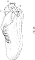
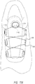
- FIG. 1 is a perspective view of an embodiment of lacing system used for tightening a shoe.
- the shoe can be any suitable footwear that can be tightened around a user's foot.
- the lacing system can be used to close or tighten various other articles as described herein, such as, for example, a belt, a hat, a glove, snowboard bindings, a medical brace, or a bag.
- the lacing system can include a reel assembly 104, lace 106, and one or more lace guides 108. In the illustrated embodiment, the reel assembly 104 can be attached to the tongue 110 of the shoe.
- Various other configurations are also possible.
- the reel assembly 104 can be attached to a side of the shoe, which can be advantageous for shoes in which the shoe sides 112a-b are designed to be drawn closely together when tightened, leaving only a small portion of the tongue 110 exposed.
- the reel assembly 104 can also be attached to the back of the shoe, and a portion of the lace 106 can pass through the shoe, sometimes using tubing for the lace to travel through, on either side of the user's ankle such that the lace 106 can be engaged with the reel assembly 104 when back-mounted.
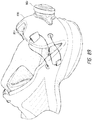
- FIG. 2 is a perspective view of an embodiment of a lacing system 200 that can be similar to the lacing system of FIG. 1 , or any other lacing system described herein.
- the lacing system 200 can include a reel assembly 204 which can be similar to reel assembly 104, or any other reel assembly described herein.
- FIGs. 3 and 4 are exploded perspective views of the reel assembly 204.
- the reel assembly 204 can include a base member 214, a spool member 216, and a knob 218.
- the base member 214 can include a housing 220 and a mounting flange 222.
- the housing 220 can include a plurality of housing teeth 224, which can extend radially inwardly.
- the housing 220 can also include lace holes 226a-b that allow the lace 206 to enter the housing 220.
- the spool member 216 can be disposed within the housing 220 such that the spool member 216 is rotatable about an axis 228 with respect to the housing 220.
- the lace 206 can be secured to the spool member 216 such that when the spool member 216 rotates in a tightening direction (shown by arrow A) the lace 206 is drawn into the housing 220 and is wound around the channel 230 formed in the spool member 216, and when the spool member 216 rotates in a loosening direction (shown by arrow B) the lace 206 unwinds from the channel 230 of the spool member 216 and exits the housing 220 via the lace holes 226a-b.
- the spool member 216 can also include spool teeth formed thereon. It will be understood that the embodiments disclosed herein can be modified such that rotation in the direction shown by arrow B will tighten the lacing. In this particular embodiment, the knob 218 may be raised axially to disengage the knob 218 from the spool 216 in order to allow the spool to freewheel in direction B in order to release the lace. In other embodiments, rotation of the knob 218 in the direction shown by arrow B may loosen the lacing system.
- the knob 218 can be attached to the housing 220 such that the knob 218 can rotate about the axis 228 with respect to the housing 220.
- the knob 218 can include knob teeth 234 that can be configured to mate with the spool teeth of spool member 216 to couple the knob 218 to the spool member 216 such that rotation of the knob 218 in the tightening direction causes the spool member 216 to also rotate in the tightening direction.
- the rotation of the knob 218 in the loosening direction can also cause the spool member 216 to rotate in the loosening direction.
- the knob 218 can also include one or more pawls 236 which can be biased radially outwardly so as to mate with the housing teeth 224.
- the pawls 236 and housing teeth 224 can be configured so that the housing teeth 224 can displace the pawls 236 radially inwardly when the knob member 218 is rotated in the tightening direction, thereby allowing the knob member 218 to rotate in the tightening direction.
- the pawls 236 and the housing teeth 224 can also be configured so that they engage one another when force is applied to twist the knob member 218 in the loosening direction, thereby preventing the knob member 218 from rotating in the loosening direction.
- the reel assembly 204 can provide a one-way tightening system that allows the user to rotate the knob 218 in the tightening direction, which causes the spool member 216 to rotate in the tightening direction, which in turn causes the lace 206 to be drawn into the housing 220 via the lace holes 226a-b.
- the lacing system 200 can tighten, causing the lace guide 208 to be drawn in the direction toward the reel 204 (shown by arrow C in FIG. 2 ).
- the lacing system 200 is shown with a single lace guide 208, any other suitable number of lace guides can be used.
- Other feature of the reel and lacing system are described in U.S. Patent Application No. 2011/0266384, filed April 29, 2011 , and Titled "Reel Based Lacing System".
- the embodiments described herein generally describe ways in which a shoe, brace, or other device may be custom or tailor fit to a user.
- the customized fit may be provided by providing a sufficient amount of "hold” or tightening in desired areas of the foot, such as: heel hold, mid-foot fit or hold, saddle fit or hold.
- the shoe's "heel hold” may be divided into three categories, specifically: the width of the heel pocket, the Achilles area (i.e., the fit of the shoe about the Achilles), and the adjustability of the ankle or rake of the heel counter.
- the heel hold i.e., the width of the heel pocket, rake of the heel counter, and the like
- Heel hold may be provided by squeezing the shoe above the calcaneus, preferably on the medial and lateral sides, which squeeze may be achieved via a compressible collar.
- lace of a closure system such as those described in FIGs. 1-4 , may be inserted within a shoe's collar in order to apply pressure to the top portion of the heel when the lace is tensioned via reel assembly. In such embodiments, tensioning of the lace will shrink the collar circumference of the shoe around the user's foot.
- the amount of perpendicular or closure force applied to the foot may be modified by configuring the shoe with force free and/or compression free regions.
- tubing 622 may be run through or along the shoe and lace 604 inserted through the tubing 622.
- the tubing 622 may be considered an incompressible solid body that resists compression as the lace 604 is tensioned. In this manner, a force and/or pressure will not be applied or transferred to the foot in regions that are coupled or otherwise include tubing 622 as the lace is tensioned.
- the tubing 622 may be discontinuous, or stated differently have separated tube portions, to create regions or zones 620 where a force or pressure may be applied as the lace 604 is tensioned.
- the shoe 630 may be configured to have one, two, or more force application regions 620 where the tubing 622 is discontinuous or individual tube segments are separated. As the lace 604 is tensioned via reel assembly 602, the shoe's collar is compressed around the user's foot due to regions 620 of discontinuous tubing. The force or pressure may not be applied in regions of the shoe that are coupled with the tubing 622.
- FIGs. 5A and 5B the shoe 630 may be configured to have one, two, or more force application regions 620 where the tubing 622 is discontinuous or individual tube segments are separated.
- the shoe's collar is compressed around the user's foot due to regions 620 of discontinuous tubing.
- the force or pressure may not be applied in regions of the shoe that are coupled with the tubing 622.
- FIG. 5A and 5B is an "open design" where the lace 604 spans the open regions 620.
- webbing 640 may be attached to the shoe 630 to span the compressible regions 620 as shown in FIG. 6A .
- the webbing 640 may be a flexible or elastic material that stretches or expands and contracts as the shoe's collar is compressed or constricted about the user's foot.
- the "open" design of FIGs. 5A and 5B and/or the webbing 640 of FIG. 6A prevent or reduce buckling of the shoe's material as the shoe's collar compresses about the user's foot.
- tubing, or tubing segments, throughwhich the lace is disposed may have compressible regions that allow a compression force to be applied at desired areas along or about the shoe.
- the compressible regions allow for the application of a force even though the tubing or tubing segments are generally incompressible.
- the compressible regions may be provided by a "tube in tube” configuration, where a first or inner tubing segment 608a is slidingly inserted within a second or outer tubing segment 608b. Specifically, a distal end of the inner tubing 608a is slidably positioned within a proximal end of a lumen of outer tubing 608b.
- Lace 604 is disposed within the lumens of inner tubing 608a and outer tubing 608b.
- the inner and outer tubing, 608a and 608b are coupled with the shoe and extend along at least a portion thereof, which may be on a side of the shoe's collar, or around the shoe's heel as illustrated in FIG. 6D , and/or elsewhere along the shoe.
- the inner and/or outer tubing, 608a and 608b, and/or portions thereof may be disposed within the outer material layer of the shoe so as to be hidden from view.
- the inner tubing 608a slides within the outer tubing 608b and compression is applied to the foot along the tubing segments and/or at the mating location of the tube segments. Compression of the inner tubing 608a and outer tubing 608b about the shoe's collar, or elsewhere relative to the shoe, tightens the shoe about the user's foot.
- the outer tubing 608b may have one or more stops that limit sliding of the inner tubing within the outer tubing. In this manner, the amount of compression applied to desired regions of the foot may be more approximately controlled and/or limited.
- the tubing segments may have multiple compressible areas, such as by having multiple tube-in-tube configurations or locations.
- Specific compression about the foot may be provided via the arrangement of the compressible regions about the shoe.
- the proximal end of the outer tubing 608b and/or inner tubing 608a, or at least a portion thereof may be transparent so that sliding of the inner tubing 608a within the outer tubing's lumen 608b is viewable to a user.
- the distal end of the inner tubing 608a and the proximal end of the outer tubing 608b may be uncoupled from the shoe so that buckling of the shoe's material is reduced or prevented as the inner tubing 608a slides within the outer tubing's lumen 608b.
- the distal end of the inner tubing 608a and the proximal end of the outer tubing 608b may be coupled with a flexible material, such as webbing 640, so that buckling of the article is reduced or prevented as the inner tubing 608a slides within the outer tubing's lumen 608b.
- FIG. 6D illustrates the tube-in-tube configuration positioned around the shoe's collar to apply pressure at the back of the foot and/or at the medial and lateral sides of the foot. It should be realized that various other configurations are possible.
- a third tubing segment may be coupled with the shoe and extend along at least a portion thereof.
- the lace 604 may be disposed within a lumen of the third tubing segment and a distal end of the third tubing segment may be slidably positioned within the lumen of the inner tubing 608a or outer tubing 608b.
- tensioning of the lace 604 may cause the third tubing to slide within the lumen of the inner or outer tubing, 608a or 608b.
- a method for coupling a tube-in-tube configuration to a shoe may include coupling a reel assembly with the shoe, coupling a first tubing with the shoe, and coupling a second tubing with the shoe.
- the first and second tubing may each extend along at least a portion of the shoe, such as around the collar or heel of the shoe.
- the first and second tubing may also each have a proximal end, a distal end, and a lumen that extends between the proximal and distal ends.
- the method may also include inserting a distal end of the second tubing within a proximal end of the first tubing's lumen so that the distal end of the second tubing is slidably disposed within the proximal end of the first tubing's lumen.
- the lacing system's lace may be inserted through, or otherwise disposed within, the lumens of the first tubing and the second tubing.
- the lace may be coupled with the reel assembly so that the lace is tensionable by operation of the reel assembly. As described herein, tensioning of the lace causes the second tubing to slide within the first tubing's lumen and thereby adjusts the tightness of the shoe about a user's foot.
- a third tubing could likewise be coupled with the shoe and have a distal end positioned within the lumen of the first or second tubing so that tensioning of the lace causes the third tubing to slide within the first or second tubing's lumen.
- FIG. 6B illustrates another embodiment that may be used to provide heel hold or collar compression.
- webbing may be used to compress the shoe's collar.
- a first webbing segment 614 crosses a second webbing segment 612 at a center point or transition ring 616.
- a force is transferred to first and second webbing segments, 614 and 612, that compresses the collar of the shoe about the user's foot.
- the compression of the shoe or article against the body surface as provided by the embodiments described herein may also be applied to various medical applications.
- the tube-in-tube configuration, webbing segments, and the like may be used in a brace that applies compression to an area of the body, such as in an ankle brace, arm brace, and the like.
- the provided compression may be part of a therapeutic treatment plan for the body part, such as healing sprains (e.g., ACL, PCL sprains or tears), tears, fractures, bone brakes, and the like.
- the compression may be applied with heat or cold, such as by placing an ice or heat pack within the brace and tensioning the lace to compress the area of the body in contact with the ice or heat pack.
- a single reel could be provided that drives multiple spool segments and/or winds multiple lace segments.
- two or more separate spools, 610 and 611 could be positioned adjacent one another and rotated or driven via a single reel assembly 613.
- Each of the spools, 610 and 611 may include gear teeth that allow the spools to be driven via the single reel assembly 613.
- the spools, 610 and 611 could be geared at different ratios so that the spools, 610 and 611, are driven or rotated at different rates by the single reel assembly 613 and thereby differentially tension lace coupled with the spools.
- a clutch mechanism could be used to cause differential rotation of the spools, 610 and 611, and thereby differentially tension lace coupled therewith. Differentially tensioning the lace may be performed to differentially or zonally tighten the shoe or other article about the user's foot or body part as described herein.
- a spool 620 may have multiple channels that prevent or limit tanging of lace segments coupled therewith.
- spool 620 may include a first channel of portion 621 around which a first lace is wound (not shown), and may include a second channel or portion 623 and/or third channel or portion 625 around which a second and/or third lace is wound (not shown).
- the first, second, and/or third channels (621, 623, and/or 625) are separate from one another and divided by a wall or barrier that prevents tangling of the laces coupled therewith.
- One or more of the channels may have the same diameter central body portions as shown in embodiment 620, or may have different diameter central body portions as shown in embodiment 632.
- the varying diameter body portions of embodiment 632 allows separate lace segments coupled with the individual channels to be wound or tensioned at different rates. Accordingly, differential tightening and/or zonal adjustment of the shoe or article may be achieved via a single reel assembly.
- the lace materials and/or properties used for the different spools and/or channels may be varied to further achieve differential or zonal shoe/article tightening.
- FIG. 7A illustrates a tensioning mechanism or reel assembly 650 that is configured to tension a plurality of individual and/or separate lace segments. Specifically, a proximal end of a first lace 652, a second lace 654, a third lace 656, and the like, is coupled with reel assembly 650. Each lace may be coupled with a separate or individual spool, or a lace channel of a spool, such as is illustrated in FIGs. 7B and 7C .
- a distal end the first lace 652, second lace 654, or third lace 656, or a distal end of each lace may be coupled with the shoe or other article or with a guide member (i.e., 653, 655, and the like) that is positioned within a zone of the shoe or otherwise coupled with the shoe.
- a guide member i.e., 653, 655, and the like
- the first lace 652, the second lace 654, and/or the third lace 656 may each be positioned within separate zones so that tensioning of the laces differentially tensions the separate zones of the shoe or article.
- the distal ends of the first lace 652, the second lace 654, and/or the third lace 656 are adjustable relative to the shoe/article to vary a length of the respective lace within the respective zone.
- the lace ends of the first lace 652, the second lace 654, and/or the third lace 656 include components or adjusters, such as cams, snaps, hooks, crimps, knots, and the like, that allow the termination points of the lace ends to be adjusted about the article and thereby vary the length of the respective lace within the respective zone.
- the components or adjusters may engage with guide member or termination points, 653, 655, and the like, to prevent proximal movement of the lace about the shoe/article.
- the cams, snaps, hooks, crimps, knots, and the like may be positioned within a channel or aperture of the termination points, 653 and 655, to prevent movement of the lace.
- the lace may be pulled distally of the termination point to shorten the lace length of a respective lace.
- the distal end of the laces may include a tab that is graspable by a user to enable the user to adjust the distal end of the first tension member relative to the article.
- the embodiments described herein allow the shoe to be custom fit in a relatively quick manner, which allows the user to quickly and conveniently close the shoe over the foot while providing a customized fit. Stated differently, the embodiments described herein enable one type of shoe to fit a wide variety of foot volumes and foot shapes.
- the above described spools could be geared in a vertical or horizontal arrangement, such as by using planetary gears.
- multiple spools may be driven at different rates with a planetary intermediary gear that is able to provide varying spool speeds.
- the spools could be belt driven, such as by a small cog belt or friction belt (e.g., rubber belt).
- the shoe's heel counter may be flexible or adjustable by tensioning the lace.
- the heel counter 830 may be hinged to the shoe's sole to allow the heel counter 830 to pivot and press against the back of the user's foot.
- the lace 804 may be coupled with the heel counter 830 so that tensioning the lace 804 via reel assembly 802 pulls the heel counter 830 forward and into contact with the user's heel.
- the attachment point of the lace and heel counter 830 may be adjusted (e.g., vertically) to allow the user to adjust the pull of the lace on the heel counter 830 and/or the pressure of the heel counter 830 on the back of the user's foot.
- Areas of portions of the collar may also be stiffened as the heel counter is adjusted, to tighten the shoe around the user's heel as desired.
- the material of the medial and/or lateral sides of the shoe positioned just forward of the heel counter may be removed so that the shoe comprises an "open" configuration between the heel counter and the front of the heel as shown in FIGs. 8A and 8B .
- the lace (or multiple laces) may traverse the open area and couple with the heel counter 830.
- webbing may traverse the open portion between the heel counter 830 and forward portion of the shoe.
- a split plate or member may be integrated with the heel counter.
- the split plate or member may have a separated center portion that may be pulled together with the lace 804 and reel assembly 802 to apply compression to the heel of the foot.
- external straps may be pulled via the reel assembly 802 and/or lace 804 to apply a force or compression to the foot.
- the lace 804 may cross the "open" portion of the shoe multiple times to increase the closure force of the heel counter 830 about the user's heel.
- the lace 804 may be inserted through tubing that directs the lace 804 to the front of the shoe and/or along the shoe's tongue portion.
- a single reel assembly 802 may be used to close the heel counter 830 about the user's heel and to close the shoe about the forefront of the foot.
- the multiple lace crossings about the "open" portion of the shoe may aid in closing the heel counter 830 about the heel in comparison to closing the forefront of the shoe.
- the curvature or shape of the shoe may be changed as the lace is tensioned.
- the lace 904 may initially be straight and a portion or area of the shoe flat.
- the lace 904 or portion of the shoe may curve as the lace 904 is tightened via reel assembly 902.
- a member or compression panel 906 may be configured to bow inward as the lace 904 is tensioned to force the portion of the shoe inward against the user's foot.
- the curved portion of the shoe, or compression member 906, may "pinch" or press against a desired portion of the foot, such as the calcaneus, to apply pressure to that area.
- the compression member 906 may be controlled with an independent reel (not shown) or share a reel with other portions of the shoe that are tensioned.
- the shoe may include one or more members (e.g., plastic pieces) with a hinge built therein and a lace track in the back so that when the lace is tensioned, the one or more members provide the desired curvature.
- the curved portion of the shoe can include various deflectable or elastic members and may be positioned at various areas where a "pinch" or similar compression is desired.
- the lacing system and/or reel assembly may be used to provide "zonal" tensioning.
- zonal tensioning means that separate or individual portions or regions of the shoe or article are differentially tightened.
- Zonal tensioning may improve the fit of the shoe about the foot, or the fit of an article about the body, by allowing the individual or separate portions/regions to be tightened about the foot in a customized and/or desired manner.
- the upper region of the shoe may be tightened at a differential rate from the forefront of the shoe, which may increase the fit or hold of the shoe about the foot.
- the heel or collar of the shoe may be differentially tightened from the forefront to increase the hold of the shoe about the heel.
- the differential tightness may be adjusted or configured based on an activity of the user, or based on a desired fit or wear of the shoe. Differential tightening also allows the shoe to be tailored or customized to unique and individual foot shapes and sizes, which increases the comfort and/or fit of the shoe about the unique foot.
- the embodiments include a first guide member that is coupled with the article (hereinafter shoe) and positioned within a first zone of the shoe.
- the embodiments also include a second guide member that is coupled with the shoe and positioned within a second zone of the shoe. At least a portion of the second zone may be different than the first zone.
- the embodiments may also include other guide members that are positioned within the first zone, the second zone, and/or other zones of the shoe.
- a first tension member (hereinafter first lace) is guided by the first guide member within the first zone of the shoe. Tensioning of the first lace causes tightening of the first zone of the shoe.
- a second tension member (hereinafter second lace) is guided by the second guide member within the second zone of the shoe. Tensioning of the second lace causes tightening of the second zone of the shoe.
- the embodiments may also include other laces that are guided by guide members within the first zone, second zone, and/or additional zones.
- a tensioning mechanism or reel assembly (hereinafter reel assembly) is also coupled with the shoe and with the first lace and second lace.
- the reel assembly is configured to tension the first lace and second lace to tighten the first and second zones.
- the reel assembly may be operated to differentially tension the first lace and the second lace, and thereby differentially tighten the first and second zones of the shoe.
- the shoes may be custom fit by using multiple laces that attach to a spool and/or by using lace ends that may be adjustable or fit into an adjustable lace end as describe in FIGs. 7A-C .
- FIGs. 10A-12N illustrate various embodiments of zonal tensioning systems and components.
- FIG. 10E shows an embodiment that utilizes a single tension zone.
- the lace when the lace is tensioned, via a reel assembly, the lace throughout the single zone is approximately equally tensioned, accounting for any frictional losses.
- the other embodiments illustrated in FIGs. 10A-12Q may be used to differentially tension individual tension zones of the shoe.
- the closure system may include multiple laces that are configured to tighten separate zones of the shoe and that have lace ends that terminate in or adjacent the separate zones.
- the lace ends may be adjustable relative to the shoe and/or separate zones to vary the length of the lace available for tightening the respective zone.
- the lacing system may include a first lace 1002 that crosses the shoe's tongue and terminates in a first lace end 1012.
- the lace path of the first lace 1002 may represent a first zone of the shoe.
- the lacing system also includes a second lace 1004 that crosses the shoe's tongue and terminates in a second lace end 1014.
- the lace path of the second lace 1004 may represent a second zone of the shoe.
- the first and second laces, 1002 and 1004 may be differentially tensioned to differentially tightened the first and second zones of the shoe, and thereby vary the force applied by the shoe on the user's foot.
- the length of the first and/or second lace, 1002 and 1004 may be adjusted or varied within the respective zones to allow the zones to be differentially tightened.
- the first lace 1002 may include an adjustment component or system, such as those described in FIG. 7A or described elsewhere herein, that allows the first lace end 1012 to be varied relative to the shoe.
- the second lace 1004 length may likewise include an adjustment component that allows the second lace end 1014 to be adjusted relative to the shoe. Subsequent operation of the reel assembly may differentially tension the first and second laces, 1002 and 1004. Additional methods of varying the lace ends are described hereinbelow.
- FIG. 10B illustrates another embodiment of zonal tensioning.
- the lacing system includes three zones having a first lace 1022 that terminates at a first lace end 1023, a second lace 1024 that terminates at a second lace end 1025, and a third lace 1026 that terminates at a third lace end 1027.
- a single reel assembly tensions all three laces, 1022, 1024, and 1026.
- the lace lengths of one or more of the laces, 1022, 1024, and 1026 may be adjusted to provide a desired and/or differential tension and pressure in each zone.
- the lace ends of one or more of the respective laces may include adjustment members that allow the ends to be adjusted relative to the shoe as described herein.
- one or more of the laces may be routed to the various zones via tubing that is coupled with the shoe.
- FIGs. 10C and 10D illustrate another embodiment of zonal tensioning.
- a first lace 1032 may wrap around the collar of the shoe and define a first tension zone while a second lace 1034 crisscrosses the shoe's tongue and defines a second tension zone.
- the first lace 1032 may traverse through a fabric sleeve and/or tubing (e.g., via tube-in-tube configuration of FIG. 6C and 6D ) and may compress the collar around the user's ankle while the second lace 1034 applies pressure to the forefront of the user's foot.
- both ends of the first lace 1032 may be coupled with the reel so that operation of the reel pulls on both ends of the lace.
- one end of the first lace 1032 may be terminated and/or adjustable (not shown).
- the second lace 1034 may terminate in a lace end 1035, which may allow for adjustment of the lace length.
- both ends of the second lace 1034 may couple with the reel assembly as shown in FIG. 10D .
- FIG. 10F illustrates another embodiment of providing zonal tensioning.
- a first lace 1042 may traverse an upper region of the shoe's tongue and terminate at a first lace end, or couple with the reel assembly 1043, to define a first tension zone adjacent the upper region of the shoe's tongue.
- An end of the first lace 1042 may be adjustable as described herein.
- the first lace 1042 may be guided by first guides 1041 that are positioned within the first tension zone.
- a second lace 1044 may traverse a lower portion of the shoe's tongue and terminate at a second lace end 1045 to define a second tension zone adjacent the lower region of the shoe's tongue.
- the second lace end 1045 may be adjustable as described herein.
- the second lace 1044 may be guided by second guides 1046 that are positioned within the second tension zone.
- the first and/or second lace, 1042 and 1044 may traverse the respective zones of the shoe in a square or crisscrossing manner as shown in FIG. 10F .
- Reel assembly 1043 may be operated to differentially tension the first and/or second lace, 1042 and 1044, and thereby differentially tighten, or apply zonal pressure, to the first and second tension zones as described herein, which may custom fit the shoe about the user's foot.
- the reel assembly in FIGs. 10A-F is generally descried as differentially tensioning the lace and differentially tightening the shoe, it should be realized that in some embodiment, the tension in the individual laces and/or separate zones of the shoe may be roughly the same. In such embodiments, operation of the reel assembly may roughly equally tension the lace and/or equally tighten the separate zones.
- FIG. 10G illustrates another embodiment of zonal tensioning.
- a first lace 1054 is guided by first guide members 1056 that are positioned within and define a first zone 1057 about the tongue of the shoe. Both ends of the first lace 1054 are coupled with a reel assembly 1052 and are tensionable thereby to tighten the first zone 1057 about an upper portion of the user's foot.
- a second lace 1055 is guided by second guide members 1058 that are positioned within and define a second zone 1059 about the tongue of the shoe. At least a portion of the second zone 1059 is different than the first zone 1057 although the two zones may overlap to some degree so that tensioning of one or both laces tightens both zones to some small degree.
- Both ends of the second lace 1055 are coupled with the reel assembly 1052 and are tensionable thereby to tighten the second zone 1059 about a lower portion of the user's foot. Coupling both ends of the first and second lace, 1054 and 1055, with the reel assembly 1052 may provide an improved closure and fit of the shoe about the user's foot.
- the first zone 1057 may include two guide members 1056 while the second zone 1059 includes four guide members 1058.
- the number of guide members used in each zone may be varied and/or the first and second laces, 1054 and 1055, may each be guided by one or more of the same guide members.
- an initial tension of the first and/or second lace, 1054 and 1055 may be varied to affect the differential tightness applied and/or achieved in each zone.
- the lace adjustment mechanisms described in FIGs. 12A-Q , and particularly 12O-Q may be used to vary the initial tension in the first and/or second lace, 1054 and 1055, as desired.
- first guide members 1056 and/or second guide members 1058 may have an open back or open channel configuration that allows the respective lace to be removed or uncoupled from the guide. The lace may then be coupled with an adjacent guide member as shown in FIG. 12O .
- first guide members 1056 and/or second guide members 1058 may be positioned on a track that allows the guide member to be proximally and distally moved relative to the shoe as shown in FIGs. 12P and 12Q .
- FIGs. 11A-11D illustrate various embodiments that may be employed to differentially tension lace and/or differentially tighten zones. Differential lace tension/zone tightness is typically achieved by varying the length of the lace within a respective zone. The embodiments of FIGs. 11A-11D illustrate various methods in which lace length within zones of a shoe may be varied.
- zonal pressure or differential tightness may be achieved by employing a "teeter” or adjustment mechanism.
- the "teeter” or adjustment mechanism is used to adjust a respective amount of lace within a zone that is tensioned via a reel assembly.
- the term “teetering” generally means lengthening a lace within one zone while shortening another lace in a separate zone by a corresponding amount.
- Such teetering or lace adjustment may be achieved using a special reel mechanism. For example, a first end of a lace may be pulled or moved out of a first port of the reel mechanism while a second and opposite end of the lace is drawn into a second port of the reel mechanism.
- the reel assembly may also function as the teeter or adjustment mechanism.
- FIG. 11A illustrates one embodiment of a teeter or adjustment mechanism 1102 (hereinafter teeter mechanism).
- a single lace is positioned through the teeter mechanism 1102 with a first portion 1104 exiting and positioned on a first side of the teeter mechanism 1102 and a second portion 1106 exiting and positioned on a second side of the teeter mechanism 1102 opposite the first side.
- the first portion 1104 terminates at a first end 1102 while the second portion terminates at a second end 1105, which may be adjacent a forefront of the shoe.
- the relative lengths of the first portion 1104 and the second portion 1106 may be adjusted by pulling the lace through the teeter mechanism 1102, which increases the tension in either the first portion 1104 or second portion 1106 while decreasing the tension in the other portion. Subsequent operation of the reel assembly, which may be the same mechanism as teeter mechanism 1102, differentially tensions each lace portion, 1104 and 1106, thereby applying a differential zonal pressure or tightness.
- the first portion 1104 and second portion 1106 may have an relatively equal tension (upper image) so that operation of the reel assembly (e.g., teeter mechanism 1102) applies an approximately equal tension in both lace portions.
- the first portion 1104 may be pulled through the teeter mechanism 1102 (e.g., through a channel) so that the lace is unbalanced on opposing sides with the first portion 1104 having a relatively greater lace length and less lace tension.
- the second portion 1106 may be pulled through the teeter mechanism 1102 so that the lace is unbalanced on opposing sides with the second portion 1106 having a relatively greater lace length and less lace tension.
- Subsequent operation of the reel assembly (e.g., teeter mechanism 1102) in the unbalanced state creates differential tension in the first and second lace portions, 1104 and 1106, and differential zonal pressure or tightness within the shoe.
- the first and second portions, 1104 and 1106, may be traversed across the shoe in any desired manner to provide a desired zonal pressure configuration and/or effect.
- the lace may be pulled through the teeter mechanism 1102 by hand when the reel assembly is in an lace setting state, or other components (not shown) may be used to pull the lace through the teeter mechanism 1102.
- FIG. 11C illustrates a teeter system that uses a teeter mechanism or device 1102 that is separate from the reel assembly 1110.
- the lacing system may include a first lace or lace portion 1104 that is coupled with the reel assembly 1110 and that traverses along or about a first zone of the shoe.
- the first lace 1104 terminates at the teeter mechanism 1102.
- the lacing system also includes a second lace or lace portion 1106 that likewise is coupled with the reel assembly 1110 and that traverse along or about a second zone of the shoe.
- the second lace 1106 likewise terminates at the teeter mechanism 1102.
- each end of the lace, 1104 and 1106, may be pre-wound onto or about teeter mechanism 1102 by at least one revolution.
- the laces, 1104 and 1106, may be would in opposite directions so that turning the knob of teeter mechanism 1102 winds one of the laces, 1104 and 1106, out of a first port while winding the opposite lace into a second port.
- Increased prewinding of the lace, 1104 and 1106, about teeter mechanism 1102 may increase, or provide additional, stroke as desired.
- the tension in each lace may be adjusted so that operation of the reel assembly 1110 differentially tensions the respective laces, 1104 and 1106, by a desired amount to apply a desired differential zonal pressure or tightness.
- Embodiments of winding the lace, 1104 and 1106, about the teeter mechanism 1102 are illustrated in FIG. 11D .
- the teeter mechanism 1102 may include a two-tiered spool arrangement that is positioned within a housing.
- the two-tiered spool may or may not include different diameter spools as described previously. Rotation of the spool via teeter mechanism 1102 may vary the lengths of the first and second laces, 1104 and 1106.
- the teeter mechanism 1102 may be a lever, a cam, a pull through spool device, and the like.
- teeter mechanism 1102 may be a second reel assembly that may have a configuration and/or function similar to reel assembly 1110.
- a knob of the second reel assembly i.e., teeter mechanism 1102
- teeter mechanism 1102 may be rotated to wind first lace portion 1104 or second lace portion 1106 about a spool of the reel assembly while unwinding the other lace portion from the spool.
- the lace tension in one of the lace portions may be increased while the lace tension in the other lace portion is simultaneously decreased.
- the second reel assembly may be used to influence the lace length and/or initial lace tension in the first and second zones and thereby zonally or differentially tension the lace.
- multiple tracks or panels, multiple guides, and/or one or more crossover points may be used to create differential tension with a single reel.
- the shoe may be fitted with multiple areas where releasing guides may be attached so that the tension applied in one or more zones may be adjusted based on the specific user.
- the lace length may be adjusted at the lace ends or termination points to vary an initial tension in respective laces (i.e., prior to operation of a reel assembly).
- FIGs. 12A-12Q illustrate various embodiments in which the ends of a lace may be adjusted. These embodiments may be employed in the device illustrated in FIG. 7A wherein the lace ends are each adjustable to differentially tension the lace and/or differentially tighten various zones of a shoe or article.
- FIGs. 12A and 12B illustrate a ball and string, or cylinder and string, concept for adjusting lace length.
- a distal portion of the lace may include "balls/cylinders" 1204 or enlarged portions, which fit and lock within grooves or recessed lace ends 1202.
- the lace may be pulled until a desired tension or lace length is achieved and a ball/cylinder or enlarged portion 1204 adjacent the recessed end 1202 may be inserted within the recessed end 1202 to lock the lace in place.
- the lace may be coupled with a ratchet system, 1206 and 1208, that allows the lace length to be adjusted by operation of the ratchet device 1208.
- the lace may be coupled with a ratchet track 1206 that is moved proximally and distally via ratchet device 1208. Movement of the ratchet track 1206 cause the lace to length or shorten within a respective zone of the shoe or article.
- the lace 1210 may be coupled with a rotatable knob 1212 or cam that winds the lace around a spool to adjust the lace length.
- the knob 1212 or cam may have a limited range of motion, such as by using an internal mechanism/stop or external mechanism/stop, so that the lace length variation is limited to a defined amount.
- the lace 1214 may be coupled with a cable adjustment system, which may include a bolt or screw 1218 that is coupled with the lace 1214 and that is threaded through a nut 1216 that presses against a stop component 1220 that is anchored to the shoe or article.
- the threads of bolt 1218 and nut 1216 cause the bolt 1218 to displace relative to the nut 1216 and thereby move relative to the shoe or article. Displacement of the bolt 1218 in this manner varies the length of the lace 1214 within a zone of the shoe or article and thereby varies the tension in the lace 1214.
- FIGs. 12E-G illustrate various ladder lock systems that may be used to vary the lace length.
- the ladder lock systems include a lock 1232a-c that may be moved proximally and distally along a ladder 1230a-c, respectively, and coupled therewith to increase or decrease the lace length within a zone of the shoe or article and thereby tension the lace by a desired amount.
- FIG. 12H illustrates another embodiment of a lace length varying system. In this embodiment, the lace 1242 may be pulled through a garage or stop component 1240 until the lace 1242 has a desired tension or lace length. A ferrule 1244 may then be crimped about the lace 1242 and the lace released.
- the ferrule 1244 prevents the lace 1242 from being pulled proximally through the garage 1240.
- the lace 1254 may be pulled through a collar or housing 1250 until the lace 1254 has a desired lace length or tension.
- a set screw 1252, detent, and the like may then be screwed or positioned to pinch the lace 1254 within the collar 1250 and prevent proximal movement of the lace 1254 relative to the collar 1250.
- an excess amount of the lace may be cut and discarded if desired.
- FIG. 12K illustrates yet another embodiment of a lace length adjustment system.
- the lace 1264 may be coupled with webbing 1260 that is positioned through and coupled with a buckle component 1262.
- the webbing 1260 may include holes or other features that allow the webbing 1260 to be coupled at various positions about buckle 1262 to vary the lace 1264 length and/or tension.
- the lace 1272 may be coupled with a rack 1270 that is movable via a pinion 1274. Movement of the rack 1270 varies the lace length within a zone of the shoe or article and thereby tension the lace 1272 by a desired amount.
- opposite ends of the rack 1270 may be coupled with a first lace 1272 and a second lace 1276 so that operation of the pinion 1274 and movement of the rack 1270 "teeter” and/or adjust the relative lengths of the first and second laces, 1272 and 1276, as described herein.
- the lace 1284 may be coupled with a "worm” or "wormshaft” 1282 that may be moved proximally and distally via a worm gear 1280. Movement of the wormshaft 1282 may vary the lace length within a zone of the shoe or article and thereby tension the lace 1284 by a desired amount.
- opposite ends of the wormshaft 1282 may be coupled with a first lace 1284 and a second lace 1286 so that operation of the worm gear 1280 and movement of the wormshaft 1282 "teeter” and/or adjust the relative lengths of the first and second laces, 1284 and 1286, as described herein.
- FIG. 12J illustrates another variation of the worm gear embodiment.
- FIG. 12O illustrates an embodiment of a lace tension adjustment system.
- the illustrated shoe includes a plurality of "open-back" guide members (i.e., 1291, 1292, and 1293) that are positioned adjacent one another about a side of the shoe.
- the open-back guide members include an open channel or back configuration that allows lace to be coupled or uncoupled from a respective guide member by placing the lace over the open channel, or removing the lace therefrom, in a hook like manner.
- the lace may be removed from the open channel of one guide member and repositioned within an open channel of an adjacent guide member to increase or decrease the tension in the lace as desired.
- FIG. 12P illustrates an embodiment of a lace tension adjustment system that includes a guide member 1295 that may be moved proximally and distally within a track 1294 to vary lace tension.
- the guide member 1295 is coupled with lace as described herein and includes a boss or projection that may be removably positioned within an aperture of the track 1294.
- the track 1294 includes multiple apertures that may be coupled with the boss or projection of the guide member 1295. In this manner, the guide member 1295 may be removed from one of the apertures of track 1294, moved proximally or distally with respect to track 1294, and repositioned within another aperture of track 1294 to tension the lace as desired.
- the track 1294 may be coupled with a side of a shoe similar to the arrangement of guides 1291-1293 to allow the guide member 1295 to be moved along or about the side of the shoe similar to the embodiment of FIG. 12O .
- FIG. 12Q is similar to FIG. 12P in that a guide member 1296 may be moved proximally and distally about a side of the shoe, but differs in that the guide member 1296 is configure to move along or about a strip of webbing or fabric 1297.
- the guide member 1296 includes a ring, hook, cam, or clamp component that allows the guide member 1296 to be coupled with fabric or webbing strip 1297. In this manner, the guide member 1296 may be moved about the shoe to tension lace that is coupled therewith by a desired amount.
- the embodiments of FIG. 12O-Q may be used to affect the differential tightening of one or more zones of a shoe by varying the tension in one or more laces positioned within the respective zone.
- the lace winding system may include gross or macro adjustment features.
- FIGs. 13A-E illustrate various embodiments of gross or macro adjustment.
- the lace 1306 may be coupled with a lever 1302 that is positionable into one of a plurality of slots of a ladder system 1304 and folded over to tension the lace 1306 and provide gross or macro closure of an opening of the shoe or other device, such as a brace.
- the lace 1306 is subsequently wound via a reel assembly 1308 to provide fine or micro adjustment and/or tensioning of the lace 1306.
- the lace 1314 may be coupled with multiple foldable panels 1312 that fold over one another to tension the lace 1314 and provide gross or macro closure of an opening of the shoe or other device, such as the illustrated brace 1318.
- a reel assembly (not illustrated) may be subsequently operated to provide fine or micro tensioning of the system.
- FIGs. 13D and 13E illustrate another embodiment of a gross or macro adjustment system.
- a plurality of posts 1372 may be positioned along the shoe, such as centrally along the tongue or on one side of the shoe (or elsewhere).
- the lace 1374 may be pulled to close the shoe about the foot and a distal portion of the lace 1374 may be positioned around one of the posts 1372.
- the lace 1374 may be run through and/or around various guides 1377 as described herein. Proximally and distally moving the lace 1374 relative to the posts 1372 and positioning the lace 1374 around one of the posts 1372 provides gross adjustment of the fit of the shoe. Additional tensioning of the lace 1374 may then be achieved using reel assembly 1376 as described herein.
- the distal portion of the lace 1374 that is positioned around the posts 1372 may include a pull tab 1378 to facilitate pulling and placement of the lace 1374 about the posts 1372.
- a system may use software in fitting a shoe to an individual user. For example, an image of the user's foot may be acquired (e.g., via picture, scan, sensed pressure, and the like) and a program may be run to determines or tailor a fit of the shoe to the user. For example, in one embodiment the user may stand on a sensory pad that measures pressure points from the user's foot. Based on the input received, the system may determine or calculate an optimal fit of the shoe for the user. The system may determine that additional heal compression is needed or that increased arch support is need for the user and provide this feedback to a service provider who would custom or tailor fit the shoe for the individual.
- the lace length, lace guide configuration, lace tension, and the like may be adjusted based on the feedback provided by the system. Likewise, the lace length, termination point of individual laces, reel selection, lace guide positioning, and the like may be adjusted based on the determined or calculated fit.
- the calculations may be provided to the user and the initial adjustments performed by the user. For example, a "fit number" may be displayed to the user as the user steps on a pressure scale or other device. The user may then adjust the configuration of the lace winding system based on the fit number. A small instructional manual may be provided to the user that instructs the user on adjusting the configuration based on the calculated fit number.
- the shoe may be tailor fit to the individual user, gross adjustment of the shoe may not be needed. Rather, the gross adjustment of the shoe may be performed once and the user may only be required to perform subsequent micro-adjustments to the shoe. This may reduce the complexity of the overall closure system and provide the user with a more positive experience of the shoe closure system.
- the above process may be particularly useful for closure systems having multiple lace termination points, multiple zones, or multiple laces because these configurations are typically less "self-adjusting" than single zone or lace systems.
- the individual zones, laces, and/or termination points may be tailor fit to the user, thereby reducing the complexity of properly fitting a shoe. Minor adjustments may then be compensated for by the user, which adjustments are typically less difficult or taxing.
- the above described system may also be used in fitting medical devices or braces with the lace winding system.
- the zonal fit of the shoe about the user's foot may be adjusted by using a flexible tensioning shaft or a torsion bar.
- a rod or flexible tensioning shaft 1702 may extend along the medial or lateral side of the shoe and may be used to tension a plurality of zones of the shoe.
- a lace or strap 1704 length from the flexible tensioning shaft 1702 to each of the zones may be adjusted based on the shape of the user's foot, and/or for various other reasons, so that tensioning of the lace or strap 1704 via the flexible tensioning shaft 1702 provides a custom fit.
- the lace or strap 1704 lengths for one or each of the zones may be determined using the software and system described previously, or using any other manner.
- the lace or strap ends 1708 may be adjusted and terminated as described herein, such as by using a locking component (e.g., ladder lock, buckle, and the like) and adjusting a distal end of the lace or strap 1704 relative to the locking component.
- a locking component e.g., ladder lock, buckle, and the like
- the lace or strap 1704 may be coupled with the flexible tensioning shaft 1702 by inserting an end of the lace or strap 1704 through a slot 1706 in the flexible tensioning shaft 1702. The lace of strap 1704 may then be wound on itself via the flexible tensioning shaft 1702 and a gear mechanism 1720, which may include a reel assembly 1722 and gear 1724.
- the flexible tensioning shaft 1702 may be disposed or positioned within tubing (not shown) that is in turn disposed within on upper material of the shoe or positioned externally thereof.
- the flexible tensioning shaft 1702 may extend along an outer surface of the shoe and be coupled therewith using one or more bearings or locks (not shown).
- the flexible tensioning shaft 1702 may have an adjustable slip clutch at one or more of the zones that allows the lace or strap 1704 within one or more zones to be tensioned to or by a defined amount.
- the adjustable slip clutch may be set at a desired tension and the flexible tensioning shaft 1702 tensioned (e.g., via reel assembly 1722) until the zone or zones reaches the set tension. After reaching the set tension, the clutch may slip so that additional tension is not applied to the lace or strap 1704.
- the slip clutch 1712 is adjusted to a desired tension, the slip clutch may be "locked out” so as to slip at the desired tension.
- the tension in one or more zone, and in some embodiments each zone, may be controlled so that respective laces are tensioned by a desired amount.
- the laces or straps 1704 may be coupled with additional straps that allow gross adjustment of the individual laces and/or fine tuning of the lace or strap 1704 tension via the flexible tensioning shaft 1702 and/or slip clutch system.
- the slip clutch may also allow the overall design of the reel and lace winding system to be simplified.
- the reel may be designed to withstand over tightening by relatively strong individuals to ensure that the reel and lace winding system does not break. These design constraints may be relaxed with the use of a slip clutch since the system may only allow a defined amount of tension to be placed on the lace before the reel and/or lace winding system slip.
- the lace may terminate in one or more ends that are configured to compensate for or adjust to different lace tensions.
- lace in individual zones of the shoe may be tensioned to a desired amount.
- the lace may be coupled with webbing ends that begin to elastically deform or stretch when a defined tension is applied.
- the lace in each zone may be adjusted to deform at the same or differential tensions so that a desired tension in each zone is ultimately provided.
- the user may tension the system until a comfortable fit is achieved.
- the lace ends e.g., webbing ends
- the differential tension may also be achieved by adjusting the lace length at the termination points.
- the lace ends and/or lace length may then be "locked out" so that a desired tension is achieved in the one or more zones.
- the above described slip clutch may be used to determine an initial tension and then subsequently "locked out” so that the lace in individual zones is tensioned by approximately the same amount.
- the lace may be wound and each lace may be tensioned to a defined amount.
- the slip clutch system may be locked so that additional tensioning of the system tensions the laces in each zone by roughly the same amount.
- the lace or straps 1704 in separate zones may be differentially tensioned to differentially tighten the separate zones. This may improve the fit and/or comfort of the shoe. Differential tension may be achieved by varying the lace or strap 1704 length within the various zones. Subsequent operation of the reel assembly 1722 may then differentially tension the lace or straps 1704. The lace or strap length may be varied on the side of the shoe adjacent the flexible tensioning shaft 1702 and/or on the opposite side adjacent end 1708. In some embodiments, rotation of the flexible tensioning shaft 1702 winds approximately an equal length of the lace or straps 1704 around the rod body of flexible tensioning shaft 1702, or unwinds approximately an equal length of the lace or straps 1704 therefrom.
- FIGs. 14D and 14E illustrate another embodiment of a flexible tensioning shaft 1730 being used to tension a boot.
- the flexible tensioning shaft system includes a reel assembly 1732 and one or more gears (not shown) that rotate or twist flexible tensioning shaft 1730.
- Positioned along the longitudinal length of flexible tensioning shaft 1730 are one or more laces or straps 1728 that extend across the forefront and/or tongue of the boot.
- the laces or straps 1728 are coupled with a gross adjustment mechanism, such as a camlock or lever buckle 1740 that may be pulled, inserted into a grooved slot, and rotated to initially tension the lace or straps 1728.
- Lever mechanism 1740 may be similar to that previously described embodiments.
- the straps 1728 may be coupled with flexible tensioning shaft 1730 via slots, weld bars 1742, pinch points, buckles, and the like.
- FIGs. 14D and 14E further illustrate flexible tensioning shaft 1730 traversing several slots or channels 1738 that hold the flexible tensioning shaft 1730 in place relative to the boot and that allow the flexible tensioning shaft 1730 to be rotated to tension the laces or straps 1728.
- the shoe may include a single strap, or a few straps, that are positioned around the shoe.
- the lace of the winding system may go around the shoe, or be coupled with the strap, so that as the lace is tensioned, a single "cinch" point is created where the shoe closes or comes together.
- the lace winding system may be designed to grab a portion or portions of the body, such as the heel and mid-foot. This embodiment may be particularly useful in ankle brace applications to stabilize that portion of the foot.
- the lace winding system may pull opposite sides of the shoe together to provide this support.
- the lace winding system may be coupled with a "pita pocket" or opposite sides of the shoe near the midsole so that as the lace is tightened, the pocket or opposite sides of the show tighten, or puff up, around the user's foot in a supportive manner.
- a portion of the shoe may be adjusted to the user and then the lace winding system subsequently coupled with the shoe.
- the shoe "upper” may be elastic and may be fit to the user's foot prior to the lace winding system being coupled with the shoe.
- the shoe's upper, or any other portion of the shoe may be composed of an initial settable material, such as a thermally settable material, light settable, and the like, so that the shoe conforms to the shape of the user's foot upon the application of heat, UV light, and the like.
- a thermally formable piece of plastic e.g., Lycra
- the shoe may then be formed to the user's foot and thermally set in that position so that the shoe is essentially an approximately perfect fit.
- the lace winding system may then be coupled with the shoe and/or custom fit to the shoe to allow easy donning and doffing thereof. Custom fitting the shoe in this manner may provide a more desirable "shrink wrap" feel where the user's foot is in increased contact with and/or cushioned by the shoe material.
- a formable or elastic upper may be integrated with roughly rigid parts or pieces of the shoe so that a better fit of the shoe with the lace winding system is provided.
- the formable or elastic upper may be formed to the user's foot and "locked" in the formed shape so that the ultimate shoe system is static and not necessarily elastic.
- a deformable member may be coupled with the shoe to allow the shoe to be custom fit to the individual user.
- a deformable rod, wire, plates, shaft, and the like may be inserted within a portion of the shoe.
- the deformable member may then be bent or formed into a custom shape that allows a custom fit or closure for the specific user.
- the deformable member be hardened (e.g., work hardened, cured, and the like) so that it maintains the custom shape and the shoe is custom fit to the user.
- the deformable member may be formed external to the shoe with a specific piece of equipment or prior to inserting within the shoe.
- the deformable member may be used to shape the eyestay of the shoe.
Claims (12)
- Système de laçage pour serrer une chaussure comprenant :un premier élément de guidage couplé à la chaussure et positionné à l'intérieur d'une première zone de la chaussure ;un second élément de guidage couplé à la chaussure et positionné à l'intérieur d'une seconde zone de la chaussure, dans lequel au moins une partie de la seconde zone est différente de la première zone ;un premier élément de tension étant un premier lacet (1002) guidé par le premier élément de guidage à l'intérieur de la première zone, dans lequel la tension du premier élément de tension entraîne le serrage de la première zone de la chaussure ;un second élément de tension étant un second lacet (1004) guidé par le second élément de guidage à l'intérieur de la seconde zone, dans lequel la tension du second élément de tension entraîne le serrage de la seconde zone de la chaussure ; etun mécanisme de tension étant un ensemble enrouleur (104) couplé à la chaussure et au premier élément de tension et au second élément de tension, le mécanisme de tension étant configuré pour tendre les premier et second éléments de tension pour serrer les première et seconde zones, dans lequel l'ensemble enrouleur (104) inclut un bouton qui peut être saisi et mis en rotation par un utilisateur pour tendre les lacets (1002, 1004) qui sont enroulés autour des éléments de guidage de la chaussure,dans lequel les premier (1002) et second (1004) lacets ont des extrémités de lacets (1012, 1014) qui se terminent dans ou adjacentes aux zones séparées et qui sont ajustables par rapport à la chaussure pour faire varier la longueur du lacet (1002, 1004) disponible pour serrer la zone respective, etdans lequel le trajet de lacet du premier lacet (1002) représente la première zone de la chaussure et le trajet de lacet du second lacet (1004) représente la seconde zone de la chaussure, dans lequell'ensemble enrouleur est attaché à un côté (112b) de la chaussure, dans laquelle les côtés de la chaussure (112a, 112b) sont conçus pour être rapprochés étroitement par de multiples lacets lorsqu'ils sont serrés, le premier lacet (1002) croise la languette de la chaussure et se termine dans l'extrémité du premier lacet (1012) et le second lacet (1004) croise la languette de la chaussure et se termine dans l'extrémité du second lacet (1014), etdans lequel le mécanisme de tension entraîne l'application d'une tension différentielle sur le premier élément de tension et le second élément de tension pour serrer de manière différentielle les première et seconde zones de manière à ce qu'une région supérieure de la chaussure soit serrée à un degré différentiel par rapport à l'avant de la chaussure.
- Système de laçage selon la revendication 1, dans lequel le mécanisme de tension inclut une bobine ayant une première partie autour de laquelle le premier élément de tension est enroulé et une seconde partie autour de laquelle le second élément de tension est enroulé, dans lequel un diamètre de la première partie est différent d'un diamètre de la seconde partie de manière à ce que l'enroulement des premier et second éléments de tension autour de la bobine entraîne l'application de la tension différentielle autour des premier et second éléments de tension.
- Système de laçage selon la revendication 1, dans lequel le mécanisme de tension inclut une bobine ayant une première partie autour de laquelle le premier élément de tension est enroulé et une seconde partie autour de laquelle le second élément de tension est enroulé, dans lequel la première partie de la bobine inclut un premier canal pour le premier élément de tension et la seconde partie de la bobine inclut un second canal pour le second élément de tension, le premier canal étant séparé du second canal pour prévenir l'emmêlement des premier et second éléments de tension.
- Système de laçage selon la revendication 1, dans lequel le mécanisme de tension inclut une première bobine autour de laquelle le premier élément de tension est enroulé et une seconde bobine autour de laquelle le second élément de tension est enroulé, et dans lequel un mécanisme d'engrenage ou d'accrochage du mécanisme de tension entraîne la rotation des première et seconde bobines à différents degrés pour entraîner l'application de la tension différentielle sur les premier et second éléments de tension.
- Système de laçage selon la revendication 1, dans lequel une extrémité proximale du premier élément de tension est couplée au mécanisme de tension et une extrémité distale du premier élément de tension est couplée à l'article chaussant ou à un second élément de guidage positionné à l'intérieur de la première zone.
- Système de laçage selon la revendication 5, dans lequel une extrémité proximale du second élément de tension est couplée au mécanisme de tension et une extrémité distale du second élément de tension est couplée à l'article chaussant ou à un second élément de guidage positionné à l'intérieur de la seconde zone.
- Système de laçage selon la revendication 5, dans lequel l'extrémité distale du premier élément de tension inclut un tirant (1378) qui peut être saisi par un utilisateur pour permettre à l'utilisateur d'ajuster l'extrémité distale du premier élément de tension par rapport à la chaussure.
- Système de laçage selon la revendication 1, comprenant en outre un mécanisme d'ajustement (1102) qui est couplé aux premier et second éléments de tension, le mécanisme d'ajustement (1102) étant configuré pour faire varier une longueur des premier et second éléments de tension à l'intérieur des zones respectives de façon à faire varier le serrage différentiel appliqué sur les zones respectives par les premier et second éléments de tension.
- Système de laçage selon la revendication 8, dans lequel le mécanisme de tension inclut le mécanisme d'ajustement (1102).
- Système de laçage selon la revendication 8, dans lequel le mécanisme d'ajustement (1102) est couplé à la chaussure séparément du mécanisme de tension et adjacent aux première ou seconde zones.
- Système de laçage selon la revendication 8, dans lequel le mécanisme d'ajustement (1102) est configuré pour diminuer la longueur de l'un des éléments de tension à l'intérieur de la zone respective et pour augmenter la longueur de l'autre élément de tension à l'intérieur de la zone respective d'une quantité correspondante.
- Système de laçage selon la revendication 1, dans lequel la chaussure inclut une pluralité d'éléments de guidage à emboîtage ouvert (1291, 1292, 1293) qui sont positionnés adjacents les uns aux autres autour d'un côté de la chaussure et incluent une configuration de canal ouvert qui permet à l'un des lacets (1002, 1004) d'être couplé ou découplé d'un élément de guidage (1291, 1292, 1293) respectif en plaçant le lacet (1002, 1004) sur le canal ouvert ou en retirant le lacet (1002, 1004) de celui-ci, à la manière d'un crochet, de manière à ce que le lacet (1002, 1004) puisse être retiré du canal ouvert d'un élément de guidage (1291, 1292, 1293) et puisse être repositionné à l'intérieur d'un canal ouvert d'un élément de guidage (1291, 1292, 1293) adjacent pour augmenter ou diminuer la tension dans le lacet (1002, 1004).
Applications Claiming Priority (2)
| Application Number | Priority Date | Filing Date | Title |
|---|---|---|---|
| US201261723218P | 2012-11-06 | 2012-11-06 | |
| PCT/US2013/068814 WO2014074645A2 (fr) | 2012-11-06 | 2013-11-06 | Dispositifs et procédés de réglage de l'ajustement de chaussures |
Publications (3)
| Publication Number | Publication Date |
|---|---|
| EP2916680A2 EP2916680A2 (fr) | 2015-09-16 |
| EP2916680A4 EP2916680A4 (fr) | 2016-11-16 |
| EP2916680B1 true EP2916680B1 (fr) | 2018-12-26 |
Family
ID=50621007
Family Applications (1)
| Application Number | Title | Priority Date | Filing Date |
|---|---|---|---|
| EP13852434.3A Active EP2916680B1 (fr) | 2012-11-06 | 2013-11-06 | Dispositifs et procédés de réglage de l'ajustement de chaussures |
Country Status (3)
| Country | Link |
|---|---|
| US (2) | US9737115B2 (fr) |
| EP (1) | EP2916680B1 (fr) |
| WO (1) | WO2014074645A2 (fr) |
Families Citing this family (113)
| Publication number | Priority date | Publication date | Assignee | Title |
|---|---|---|---|---|
| WO2006050266A2 (fr) | 2004-10-29 | 2006-05-11 | Boa Technology, Inc. | Systeme de fermeture a enrouleur |
| WO2007079777A1 (fr) | 2006-01-13 | 2007-07-19 | Smm Medical Ab | Appareil, système et méthode pour traitement compressif d'une partie du corps |
| KR101688997B1 (ko) | 2008-11-21 | 2016-12-22 | 보아 테크놀러지, 인크. | 릴 기반 끈 조임 시스템 |
| DE112011100318B4 (de) | 2010-01-21 | 2023-04-20 | Boa Technology, Inc. | Führungen für Schnürsysteme |
| US9375053B2 (en) | 2012-03-15 | 2016-06-28 | Boa Technology, Inc. | Tightening mechanisms and applications including the same |
| KR101875508B1 (ko) | 2010-04-30 | 2018-07-06 | 보아 테크놀러지, 인크. | 릴 기반 끈 조임 시스템 |
| US10070695B2 (en) | 2010-04-30 | 2018-09-11 | Boa Technology Inc. | Tightening mechanisms and applications including the same |
| US9101181B2 (en) | 2011-10-13 | 2015-08-11 | Boa Technology Inc. | Reel-based lacing system |
| EP2871994B8 (fr) | 2012-08-31 | 2020-11-04 | NIKE Innovate C.V. | Système de tension motorisé à capteurs |
| US9516923B2 (en) | 2012-11-02 | 2016-12-13 | Boa Technology Inc. | Coupling members for closure devices and systems |
| US9737115B2 (en) | 2012-11-06 | 2017-08-22 | Boa Technology Inc. | Devices and methods for adjusting the fit of footwear |
| EP3607845B1 (fr) | 2013-01-28 | 2022-11-09 | Boa Technology Inc. | Ensemble et système de fixation de lacet |
| US10702409B2 (en) | 2013-02-05 | 2020-07-07 | Boa Technology Inc. | Closure devices for medical devices and methods |
| US10251451B2 (en) | 2013-03-05 | 2019-04-09 | Boa Technology Inc. | Closure devices including incremental release mechanisms and methods therefor |
| US9610185B2 (en) | 2013-03-05 | 2017-04-04 | Boa Technology Inc. | Systems, methods, and devices for automatic closure of medical devices |
| JP6302996B2 (ja) | 2013-04-01 | 2018-03-28 | ボア テクノロジー,インコーポレイテッド | リールベースのクロージャーシステムを含むようにフットウェアを後付け改装するための方法および装置 |
| US10076160B2 (en) | 2013-06-05 | 2018-09-18 | Boa Technology Inc. | Integrated closure device components and methods |
| EP3777595A1 (fr) | 2013-06-05 | 2021-02-17 | Boa Technology Inc. | Éléments d'un dispositif de fermeture intégré, et procédés |
| DE112014003135B4 (de) * | 2013-07-02 | 2020-12-24 | Boa Technology Inc. | Rolle zur verwendung mit einem verschnürungssystem zum festziehen eines gegenstandes sowie vorrichtungen hierzu und verfahren zum zusammenbauen einer vorrichtung zum festziehen eines gegenstandes |
| KR101855407B1 (ko) | 2013-07-10 | 2018-05-09 | 보아 테크놀러지, 인크. | 증분적인 해제 메커니즘을 포함하는 폐쇄 장치 및 폐쇄 방법 |
| WO2015035257A2 (fr) | 2013-09-05 | 2015-03-12 | Boa Technology Inc. | Variantes de guides de laçage pour serrer des mécanismes et procédés associés |
| KR102350912B1 (ko) | 2013-09-13 | 2022-01-13 | 보아 테크놀러지, 인크. | 릴 기반 폐쇄 장치 및 그에 따른 방법 |
| US9872790B2 (en) | 2013-11-18 | 2018-01-23 | Boa Technology Inc. | Methods and devices for providing automatic closure of prosthetics and orthotics |
| ITVR20130295A1 (it) * | 2013-12-23 | 2015-06-24 | Selle Royal Spa | Calzatura sportiva |
| ITVR20130294A1 (it) | 2013-12-23 | 2015-06-24 | Selle Royal Spa | Calzatura sportiva |
| DE102014100150B4 (de) * | 2014-01-08 | 2020-09-17 | Johannes Helmut Steuerwald | Schuh |
| USD835976S1 (en) | 2014-01-16 | 2018-12-18 | Boa Technology Inc. | Coupling member |
| TWI561453B (en) * | 2014-02-17 | 2016-12-11 | Chin Chu Chen | A device for tightening and loosening a lace |
| CN113876080A (zh) * | 2014-04-14 | 2022-01-04 | 弗莱克利普有限责任公司 | 系带调节器组件和鞋 |
| EP2952114A1 (fr) * | 2014-06-03 | 2015-12-09 | K-2 Corporation | Système de laçage zonal à enroulage unique pour chaussures de sport d'hiver |
| US20150359296A1 (en) * | 2014-06-17 | 2015-12-17 | The Burton Corporation | Lacing system for footwear |
| EP3157474B1 (fr) | 2014-06-23 | 2020-08-19 | Tactile Systems Technology, Inc. | Système de vêtement de compression doté d'un appareil de serrage |
| EP3166548B1 (fr) | 2014-07-11 | 2019-06-05 | Ossur Iceland EHF | Système de serrage avec contrôle de la tension appliquée |
| US9713357B2 (en) | 2014-07-15 | 2017-07-25 | Taylor Made Golf Company, Inc. | Asymmetric shoes |
| US20160058127A1 (en) | 2014-08-28 | 2016-03-03 | Boa Technology Inc. | Devices and methods for enhancing the fit of boots and other footwear |
| US10182935B2 (en) | 2014-10-01 | 2019-01-22 | Ossur Hf | Support for articles and methods for using the same |
| US10575591B2 (en) | 2014-10-07 | 2020-03-03 | Boa Technology Inc. | Devices, methods, and systems for remote control of a motorized closure system |
| GB2533809A (en) * | 2014-12-31 | 2016-07-06 | Start-Rite Shoes Ltd | Footwear retention arrangement and footwear item |
| US10264852B2 (en) | 2015-01-14 | 2019-04-23 | Sug Whan Kim | String winding and unwinding apparatus |
| USD835898S1 (en) | 2015-01-16 | 2018-12-18 | Boa Technology Inc. | Footwear lace tightening reel stabilizer |
| US9962273B2 (en) * | 2015-05-13 | 2018-05-08 | Ossur Iceland Ehf | Adjustable socket system |
| KR102595025B1 (ko) * | 2015-05-29 | 2023-10-26 | 나이키 이노베이트 씨.브이. | 소형 스풀 시스템을 가지는 동력형 장력화 장치 |
| US10405610B2 (en) | 2015-05-29 | 2019-09-10 | Nike, Inc. | Article of footwear comprising motorized tensioning device with split spool system |
| US9743709B2 (en) | 2015-06-03 | 2017-08-29 | Taylor Made Golf Company, Inc. | Wrap-around wire support for shoe |
| US9788599B2 (en) | 2015-06-03 | 2017-10-17 | Taylor Made Golf Company, Inc. | Torsion control bridge for shoe |
| JP2016221232A (ja) | 2015-06-03 | 2016-12-28 | テーラー メイド ゴルフ カンパニー インコーポレイテッド | 靴のための巻付きワイヤ支持 |
| DE112015006734B4 (de) * | 2015-07-27 | 2022-10-27 | Chris Lintaman | Längeneinstellbarer Schuh |
| WO2017062339A1 (fr) | 2015-10-05 | 2017-04-13 | Tactile Systems Technology, Inc. | Système de thérapie par compression statique et dynamique |
| CA3000992C (fr) | 2015-10-05 | 2024-01-02 | Tactile Systems Technology, Inc. | Vetement de compression reglable |
| CN107249376B (zh) * | 2015-10-07 | 2019-11-22 | 彪马欧洲股份公司 | 鞋 |
| US10004297B2 (en) * | 2015-10-15 | 2018-06-26 | Boa Technology Inc. | Lacing configurations for footwear |
| WO2017075228A1 (fr) * | 2015-10-27 | 2017-05-04 | Plae, Inc. | Système de fermeture de chaussure |
| US20170143528A1 (en) * | 2015-11-19 | 2017-05-25 | Joseph S. Pongratz | Methods and Devices for Correcting Pectus Carinatum |
| EP3405152B1 (fr) | 2016-01-21 | 2022-03-30 | Tactile Systems Technology, Inc. | Système de vêtement de compression |
| US10238180B2 (en) | 2016-03-15 | 2019-03-26 | Nike, Inc. | Position sensing assembly for a tensioning system |
| US10244822B2 (en) * | 2016-03-15 | 2019-04-02 | Nike, Inc. | Lace routing pattern of a lacing system for an article of footwear |
| US10390589B2 (en) | 2016-03-15 | 2019-08-27 | Nike, Inc. | Drive mechanism for automated footwear platform |
| JP6665313B2 (ja) * | 2016-03-15 | 2020-03-13 | ミズノ・ユー・エス・エイ・インコーポレイテッドMizuno Usa, Inc. | 調節可能な踵機構を有する履物 |
| US11806264B2 (en) | 2016-05-03 | 2023-11-07 | Icarus Medical, LLC | Adjustable tensioning device |
| CA2962221A1 (fr) * | 2016-07-05 | 2018-01-05 | Joseph O. M. Lawrence | Bande de tension corporelle |
| US11026472B2 (en) | 2016-07-22 | 2021-06-08 | Nike, Inc. | Dynamic lacing system |
| KR102552961B1 (ko) | 2016-08-02 | 2023-07-10 | 보아 테크놀러지, 인크. | 신발끈 결속 시스템의 인장 부재 가이드 |
| USD877459S1 (en) | 2016-08-31 | 2020-03-10 | Tactile Systems Technology, Inc. | Torso garment |
| DE102016121657A1 (de) | 2016-11-11 | 2018-05-17 | Bauerfeind Ag | Spannband |
| KR101839798B1 (ko) | 2016-11-30 | 2018-03-20 | 김진호 | 와이어 조임용 릴시스템 |
| KR20180062475A (ko) * | 2016-11-30 | 2018-06-11 | 김진호 | 릴시스템의 와이어 묶는방법 |
| KR102494446B1 (ko) | 2016-12-09 | 2023-02-01 | 보아 테크놀러지, 인크. | 릴 기반의 폐쇄 시스템 |
| JP6881993B2 (ja) | 2017-02-01 | 2021-06-02 | 株式会社アルペン | 紐巻取装置を備えた物品 |
| US10543630B2 (en) | 2017-02-27 | 2020-01-28 | Boa Technology Inc. | Reel based closure system employing a friction based tension mechanism |
| US20180255873A1 (en) * | 2017-03-10 | 2018-09-13 | Stephen Roy | Rear entering, rear fastening, improved athletic shoe |
| CN110636772B (zh) * | 2017-03-15 | 2021-11-19 | 耐克创新有限合伙公司 | 具有缆线和鞋面张紧器的自动化鞋类 |
| US11357279B2 (en) | 2017-05-09 | 2022-06-14 | Boa Technology Inc. | Closure components for a helmet layer and methods for installing same |
| USD897661S1 (en) * | 2017-06-07 | 2020-10-06 | Boa Technology Inc. | Lace tightening device |
| USD840667S1 (en) * | 2017-06-09 | 2019-02-19 | Nike, Inc. | Shoe with lacing system |
| US10772384B2 (en) | 2017-07-18 | 2020-09-15 | Boa Technology Inc. | System and methods for minimizing dynamic lace movement |
| USD870297S1 (en) | 2017-09-28 | 2019-12-17 | Tactile Systems Technology, Inc. | Trunk garment |
| USD848625S1 (en) | 2017-09-28 | 2019-05-14 | Tactile Systems Technology, Inc. | Leg garment |
| USD849254S1 (en) | 2017-09-28 | 2019-05-21 | Tactile Systems Technology, Inc. | Combination trunk and leg garment |
| WO2019090339A1 (fr) | 2017-11-06 | 2019-05-09 | Tactile Systems Technology, Inc. | Systèmes de vêtements de compression |
| US10575592B1 (en) | 2018-03-14 | 2020-03-03 | Charles M Jones | Lace tightening apparatus and method |
| GB2572789B (en) * | 2018-04-10 | 2022-11-23 | Teqnox Ltd | A body protector |
| USD877477S1 (en) * | 2018-04-13 | 2020-03-10 | Wolverine Outdoors, Inc. | Footwear upper |
| US11317677B2 (en) | 2018-05-11 | 2022-05-03 | Nike, Inc. | Article with side lacing system and method of lacing an article |
| US11116286B2 (en) | 2018-05-11 | 2021-09-14 | Nike, Inc. | Article with intermediate side lacing system and method of lacing an article |
| US11076657B2 (en) | 2018-05-11 | 2021-08-03 | Nike, Inc. | Article with zoned lacing system and method of lacing an article |
| US10654388B2 (en) * | 2018-07-13 | 2020-05-19 | Ka Group Ag | Articulating multi-body system with a displacement clutch |
| US11140940B2 (en) * | 2018-08-30 | 2021-10-12 | The Government Of The United States, As Represented By The Secretary Of The Army | Generator spinning in a wearable system |
| CN112955047B (zh) | 2018-09-06 | 2022-11-29 | 耐克创新有限合伙公司 | 具有反馈机构的动态系带系统 |
| US11524188B2 (en) | 2018-10-09 | 2022-12-13 | Checkmate Lifting & Safety Ltd | Tensioning device |
| GB201818169D0 (en) * | 2018-11-07 | 2018-12-19 | Greater Glasgow Healthboard | Motion restriction device |
| IT201900003207A1 (it) | 2019-03-06 | 2020-09-06 | 10 Ottobre S R L | Tomaia per calzature e procedimento per la produzione di tomaie per calzature. |
| EP3934472A1 (fr) * | 2019-03-07 | 2022-01-12 | Ossur Iceland Ehf | Adaptateur pour dispositif rotatif |
| USD880834S1 (en) * | 2019-04-12 | 2020-04-14 | Nike, Inc. | Shoe |
| JP7454267B2 (ja) | 2019-05-01 | 2024-03-22 | ボア テクノロジー,インコーポレイテッド | リール式クロージャーシステム |
| USD904002S1 (en) * | 2019-08-26 | 2020-12-08 | Nike, Inc. | Shoe |
| US20210093046A1 (en) * | 2019-10-01 | 2021-04-01 | Nike, Inc. | Zonal dynamic lacing system |
| WO2021163578A1 (fr) | 2020-02-14 | 2021-08-19 | Shift Holding, LLC | Bobine de changement de vitesse et procédés associés |
| USD931594S1 (en) * | 2020-03-13 | 2021-09-28 | Nike, Inc. | Shoe |
| USD943945S1 (en) | 2020-07-31 | 2022-02-22 | Specialized Bicycle Components, Inc. | Bicycle shoe |
| USD975969S1 (en) | 2020-10-27 | 2023-01-24 | Specialized Bicycle Components, Inc. | Shoe |
| USD975970S1 (en) | 2020-12-23 | 2023-01-24 | Specialized Bicycle Components, Inc. | Shoe |
| USD974005S1 (en) | 2020-12-23 | 2023-01-03 | Specialized Bicycle Components, Inc. | Shoe |
| USD975405S1 (en) | 2021-01-14 | 2023-01-17 | Specialized Bicycle Components, Inc. | Shoe |
| US20220225735A1 (en) * | 2021-01-15 | 2022-07-21 | S9, Llc | Shoelace Receiver |
| USD1014695S1 (en) | 2021-03-24 | 2024-02-13 | Shift Holding, LLC | Shift reel |
| USD983510S1 (en) * | 2021-05-03 | 2023-04-18 | Boa Technology Inc. | Lace tightening device dial |
| JP2023013847A (ja) * | 2021-07-16 | 2023-01-26 | 株式会社シマノ | 靴 |
| USD961240S1 (en) * | 2021-09-16 | 2022-08-23 | Nike, Inc. | Shoe |
| US11859446B2 (en) | 2022-01-21 | 2024-01-02 | Anthony Clark Blackburn | Cord tightening device |
| USD991778S1 (en) | 2022-01-21 | 2023-07-11 | Anthony Clark Blackburn | Cord tightening device |
| USD977239S1 (en) | 2022-03-04 | 2023-02-07 | Nike, Inc. | Shoe |
| USD1007115S1 (en) * | 2023-03-24 | 2023-12-12 | Nike, Inc. | Shoe |
| USD1000062S1 (en) * | 2023-05-08 | 2023-10-03 | Jingliang You | Shoe accessory part |
Citations (1)
| Publication number | Priority date | Publication date | Assignee | Title |
|---|---|---|---|---|
| US5117567A (en) * | 1989-06-03 | 1992-06-02 | Puma Ag Rudolf Dassler Sport | Shoe with flexible upper material provided with a closing device |
Family Cites Families (522)
| Publication number | Priority date | Publication date | Assignee | Title |
|---|---|---|---|---|
| US379113A (en) | 1888-03-06 | Chaeles james hibbeed | ||
| US59332A (en) | 1866-10-30 | Improvement in clasps for belting | ||
| US1429657A (en) | 1922-09-19 | Unitffo statfs patfnt offitf | ||
| US301854A (en) | 1884-07-15 | Geoege c | ||
| US230759A (en) | 1880-08-03 | Shoe-clasp | ||
| US371394A (en) | 1887-10-11 | Textile eyelet for corsets | ||
| US80834A (en) | 1868-08-11 | Improvement in clasp foe boots and shoes, belts foe ladies dresses | ||
| US117530A (en) | 1871-08-01 | Improvement in glove-fasteners | ||
| US228946A (en) | 1880-06-15 | Feiedeich schulz and august schulz | ||
| US460743A (en) | 1891-10-06 | Shoe-fastening | ||
| GB189911673A (en) | 1899-06-05 | 1899-07-22 | Jean Louis Edouard Bourbaud | A New or Improved Appliance for Use in Fastening Boots and Shoes. |
| US746563A (en) | 1903-03-06 | 1903-12-08 | James Mcmahon | Shoe-lacing. |
| US819993A (en) | 1905-05-09 | 1906-05-08 | William E Haws | Lacing. |
| US886779A (en) | 1907-02-16 | 1908-05-05 | William A Dunstan | Shoe-fastening. |
| US908704A (en) | 1908-04-02 | 1909-01-05 | Mahlon A Stair | Shoe-fastener. |
| US1170472A (en) | 1909-08-27 | 1916-02-01 | John Wesley Barber | Fastener for shoes, &c. |
| US1083775A (en) | 1911-10-04 | 1914-01-06 | James J Thomas | Shoe-lacer. |
| US1062511A (en) | 1912-06-19 | 1913-05-20 | Henry William Short | Boot-lace. |
| US1060422A (en) | 1912-10-22 | 1913-04-29 | Albertis Bowdish | Device for securing the flaps of boots or shoes. |
| US1090438A (en) | 1913-02-20 | 1914-03-17 | Charles H Worth | Lacing-holder. |
| US1288859A (en) | 1917-11-14 | 1918-12-24 | Albert S Feller | Shoe-lace fastener. |
| US1412486A (en) | 1920-10-06 | 1922-04-11 | Paine George Washington | Lacing device |
| US1466673A (en) | 1921-05-03 | 1923-09-04 | Solomon Julius | Shoe-lace fastener |
| US1390991A (en) | 1921-05-07 | 1921-09-20 | Fotchuk Theodor | Shoe-closure |
| US1416203A (en) | 1921-05-21 | 1922-05-16 | Hobson Orlen | Apparel lacing |
| US1393188A (en) | 1921-05-24 | 1921-10-11 | Whiteman Allen Clay | Lacing device |
| US1469661A (en) | 1922-02-06 | 1923-10-02 | Migita Tosuke | Lacing means for brogues, leggings, and the like |
| US1502919A (en) | 1922-07-10 | 1924-07-29 | Frank A Seib | Shoe |
| US1481903A (en) | 1923-04-09 | 1924-01-29 | Alonzo W Pangborn | Shoe-lacing device |
| US1505430A (en) | 1923-04-13 | 1924-08-19 | Roberts | Fastening for footwear and the like |
| GB216400A (en) | 1923-07-10 | 1924-05-29 | Jules Lindauer | An improved yielding connection between pieces of fabric, leather or the like |
| US1530713A (en) | 1924-02-11 | 1925-03-24 | Clark John Stephen Day | Lacing device for boots and shoes |
| US1548407A (en) | 1924-07-21 | 1925-08-04 | Arch J Chisholm | Shoe-lacing device |
| US1862047A (en) | 1930-07-08 | 1932-06-07 | Robert L Boulet | Shoe fastening device |
| US1995243A (en) | 1934-06-12 | 1935-03-19 | Charles J Clarke | Lacing or fastening boots, shoes, or the like |
| CH183109A (de) | 1935-07-03 | 1936-03-15 | Testa Giovanni | Sportschuh mit Vorderschluss, insbesondere als Ski- und Bergschuh geeignet. |
| DE641976C (de) | 1935-09-22 | 1937-02-18 | Otto Keinath | Schuhverschluss |
| US2124310A (en) | 1935-09-25 | 1938-07-19 | Jr Max Murr | Boot |
| US2088851A (en) | 1936-09-16 | 1937-08-03 | John E Gantenbein | Shoe top |
| CH199766A (de) | 1937-08-06 | 1938-09-15 | Ernst Blaser | Schuhverschluss. |
| CH204834A (de) | 1938-08-20 | 1939-05-31 | Romer Hans | Schuh. |
| US2316102A (en) | 1942-05-23 | 1943-04-06 | Frank W Preston | Lacing equipment |
| CH247693A (de) | 1945-11-17 | 1947-03-31 | E Mangold | Schuh, insbesondere für Sportzwecke. |
| US2500622A (en) | 1946-05-10 | 1950-03-14 | Herman Niessen | Adjustable stump support for artificial legs |
| US2611940A (en) | 1950-04-20 | 1952-09-30 | Thomas C Cairns | Shoelace tightener |
| US2636237A (en) | 1951-04-02 | 1953-04-28 | Nathaniel W Price | Flexible shoelace fastener |
| US2673381A (en) | 1951-12-13 | 1954-03-30 | Fred E Dueker | Quick lace shoelace tightener |
| US2907086A (en) | 1957-02-25 | 1959-10-06 | Lewis R Ord | Hose clamp |
| US2893090A (en) | 1958-01-24 | 1959-07-07 | Walter S Pagoda | Shoelace tightener |
| US2991523A (en) | 1959-02-10 | 1961-07-11 | Conte Robert I Del | Cord storage and length adjusting device |
| US2926406A (en) | 1959-03-27 | 1960-03-01 | Edwards George Zahnor | Length adjustment mechanism |
| US3035319A (en) | 1959-09-15 | 1962-05-22 | Harry O Wolff | Clamp devices |
| DE1190359B (de) | 1960-04-05 | 1965-04-01 | Franz Fesl | Sportschuh, insbesondere Skischuh |
| US3028602A (en) | 1960-12-19 | 1962-04-10 | Mine Safety Appliances Co | Helmet head positioner |
| US3163900A (en) | 1961-01-20 | 1965-01-05 | Martin Hans | Lacing system for footwear, particularly ski-boot fastener |
| US3106003A (en) | 1962-01-19 | 1963-10-08 | Charles W Herdman | Shoe lace knot protector |
| US3122810A (en) | 1962-05-17 | 1964-03-03 | Talon Inc | Fastening device |
| AT246605B (de) | 1963-03-06 | 1966-04-25 | Stocko Metallwarenfab Henkels | Schnürhaken für Schuhe |
| US3193950A (en) | 1963-03-26 | 1965-07-13 | Liou Shu-Lien | Fastening means for shoe laces |
| US3112545A (en) | 1963-04-15 | 1963-12-03 | Williams Luther | Shoe fastening device |
| BE650533A (fr) | 1963-07-15 | |||
| AT242560B (de) | 1963-07-18 | 1965-09-27 | Karl Piberhofer | Schnürhaken |
| US3197155A (en) | 1963-09-25 | 1965-07-27 | Rev Andrew Song | Device for tightening shoe laces |
| US3214809A (en) | 1963-12-20 | 1965-11-02 | Kedman Company | Length adjustment mechanism |
| US3345707A (en) | 1964-11-16 | 1967-10-10 | Albert M Rita | Decorative shoe lace keeper |
| CH476474A (de) | 1966-07-21 | 1969-08-15 | Martin Hans | Skischuh |
| US3430303A (en) | 1966-08-11 | 1969-03-04 | Donald E Perrin | Lace wind |
| CH471553A (de) | 1967-04-26 | 1969-04-30 | Martin Hans | Skischuh mit Einrichtung zum Zusammenziehen der Schliesslappen |
| US3401437A (en) | 1967-05-10 | 1968-09-17 | Aeroquip Corp | Hose clamp |
| DE6933746U (de) | 1968-10-05 | 1970-04-09 | Calzaturificio S Marco Tessaro | Schnuervorrichtung, insbesondere fuer skischuhe |
| CA869238A (en) | 1969-02-19 | 1971-04-27 | Shnuriwsky Michael | Sleeved boot |
| US3668791A (en) | 1969-07-08 | 1972-06-13 | Otto Salzman | Fastener for ski boots and the like footwear |
| AT296086B (de) | 1969-10-03 | 1972-01-25 | Josef Graup | Verschluß, insbesondere für Schi- oder Bergschuhe |
| US3703775A (en) | 1970-09-15 | 1972-11-28 | Joseph Gatti | Football boots |
| FR2108429A5 (fr) | 1970-09-23 | 1972-05-19 | Weinmann Ag | |
| US3729779A (en) | 1971-06-07 | 1973-05-01 | K Porth | Ski boot buckle |
| CH562015A5 (fr) | 1972-03-21 | 1975-05-30 | Weinmann Ag | |
| DE2317408C2 (de) | 1972-04-17 | 1982-12-23 | Etablissements François Salomon et Fils, 74011 Annecy, Haute-Savoie | Skischuh |
| DE2341658A1 (de) | 1972-08-23 | 1974-03-07 | Polyair Maschb Gmbh | Skischuh |
| US3845575A (en) | 1973-05-07 | 1974-11-05 | O Boden | Cord locking assembly |
| AT348896B (de) | 1974-06-20 | 1979-03-12 | Martin Hans | Verschluss fuer skischuhe |
| US3934346A (en) | 1974-12-12 | 1976-01-27 | Kyozo Sasaki | Sporting shoes |
| JPS51121375A (en) | 1975-04-16 | 1976-10-23 | Mansei Kogyo Kk | Display change switch for electronic digital watch |
| AT338410B (de) | 1975-09-18 | 1977-08-25 | Viennatone Gmbh | Getriebe fur eine orthese, prothese od.dgl. |
| AT343009B (de) | 1976-01-22 | 1978-05-10 | Dynafit Gmbh | Verschluss fur sportschuhe |
| DE2800187A1 (de) | 1977-01-07 | 1978-07-13 | Hans Martin | Ski- und eislaufschuh |
| JPS53124987A (en) | 1977-04-06 | 1978-10-31 | Mitsubishi Electric Corp | Bidirectional thyristor |
| JPS583428Y2 (ja) | 1978-01-17 | 1983-01-20 | 東成産業株式会社 | 物干し用ハンガ−ロ−プ |
| JPS54108125A (en) | 1978-02-15 | 1979-08-24 | Toyota Motor Corp | Air fuel ratio controller for internal combustion engine |
| USRE31052E (en) | 1978-05-30 | 1982-10-12 | Kaepa, Inc. | Lacing assembly for a shoe |
| US4227322A (en) | 1978-10-13 | 1980-10-14 | Dolomite, S.P.A. | Sport footwear of injected plastics material |
| DE2900077A1 (de) | 1979-01-02 | 1980-07-17 | Wagner Lowa Schuhfab | Schuhverschluss |
| US4261081A (en) | 1979-05-24 | 1981-04-14 | Lott Parker M | Shoe lace tightener |
| US4267622A (en) | 1979-08-06 | 1981-05-19 | Burnett Johnston Roy L | Hose clip apparatus |
| CA1167254A (fr) | 1980-08-11 | 1984-05-15 | Hans Martin | Chaussure ou bottine de sport |
| DE3101952A1 (de) | 1981-01-22 | 1982-09-02 | Paul 7100 Heilbronn Reim | Schuhverschlussspule |
| IT1193578B (it) | 1981-01-28 | 1988-07-08 | Nordica Spa | Dispositivo di chiusura particolarmente per scarponi da sci |
| US4394803A (en) | 1981-06-10 | 1983-07-26 | Polsam, Inc. | Elasticized overlay |
| US4417703A (en) | 1981-11-19 | 1983-11-29 | Weinhold Dennis G | Quick retrieve cord reel |
| DE3148527A1 (de) | 1981-12-08 | 1983-06-30 | Weinmann Gmbh & Co Kg Fahrrad- Und Motorrad-Teilefabrik, 7700 Singen | Verschluss fuer schuhe, insbesondere skischuhe |
| DE3234458A1 (de) | 1982-04-01 | 1983-10-13 | Sanimed Vertrieb AG, St. Gallen, 9000 St. Gallen | Staugurt |
| DE3212992A1 (de) | 1982-04-07 | 1983-10-20 | Naamloze Vennootschap Klippan S.A., 3030 Heverlee | Gurtaufrollschnellsperrautomat |
| IT8222497V0 (it) | 1982-07-22 | 1982-07-22 | Nordica Spa | Struttura di dispositivo di bloccaggio del piede particolarmente per scarponi da sci. |
| US4463761A (en) | 1982-08-02 | 1984-08-07 | Sidney Pols | Orthopedic shoe |
| US4507878A (en) | 1982-12-20 | 1985-04-02 | Hertzl Semouha | Fastening mechanism |
| US4553342A (en) | 1983-04-08 | 1985-11-19 | Nike, Inc. | Article of footwear with an adjustable width, adjustable tension closure system |
| DE3317771A1 (de) | 1983-04-26 | 1984-10-31 | Weinmann Gmbh & Co Kg Fahrrad- Und Motorrad-Teilefabrik, 7700 Singen | Skischuh mit zentralverschluss |
| FR2546993B1 (fr) | 1983-05-31 | 1985-08-30 | Salomon & Fils F | Dispositif de reglage progressif de la position relative de deux elements |
| US4924605A (en) | 1985-05-22 | 1990-05-15 | Spademan Richard George | Shoe dynamic fitting and shock absorbtion system |
| DE3502522A1 (de) | 1984-02-10 | 1985-08-14 | SALOMON S.A., Annecy, Haute-Savoie | Betaetigungshebel zum verschliessen und verriegeln eines skistiefels mit einstieg von hinten |
| IT8421234V0 (it) | 1984-03-14 | 1984-03-14 | Nordica Spa | Manopola di azionamento a dimensioni ridotte per dispositivi di regolazione e chiusura, particolarmente in scarponi da sci. |
| IT1199519B (it) | 1984-04-03 | 1988-12-30 | Kairos Di Bonetti M | Dispositivo di bloccaggio della gamba per scarpe da sci ad entrata posteriore |
| IT8421967V0 (it) | 1984-05-30 | 1984-05-30 | Nordica Spa | Scarpone da sci con dispositivo di bloccaggio del piede. |
| IT1180988B (it) | 1984-06-01 | 1987-09-23 | Caber Italia | Dispositivo di serraggio e regolazione particolarmente per scarponi da sci |
| FR2569087B1 (fr) | 1984-08-17 | 1987-01-09 | Salomon Sa | Chaussure de ski |
| FR2570257B1 (fr) | 1984-09-14 | 1987-01-09 | Salomon Sa | Chaussure de ski |
| US4654985A (en) | 1984-12-26 | 1987-04-07 | Chalmers Edward L | Athletic boot |
| US4644938A (en) | 1985-01-22 | 1987-02-24 | Danninger Medical Technology | Hand exerciser |
| CH661848A5 (fr) | 1985-03-07 | 1987-08-31 | Lange Int Sa | Chaussure de ski. |
| IT1184177B (it) | 1985-03-22 | 1987-10-22 | Nordica Spa | Scarpone da sci ad entrata posteriore con bloccaggio della zona della caviglia |
| US4616432A (en) | 1985-04-24 | 1986-10-14 | Converse Inc. | Shoe upper with lateral fastening arrangement |
| IT1184540B (it) | 1985-05-06 | 1987-10-28 | Nordica Spa | Scarpone da sci con dispositivo di chiusura dei gambali |
| IT209343Z2 (it) | 1985-09-04 | 1988-10-05 | Nordica Spa | Struttura di dispositivo di azionamento per elementi di bloccaggio del piede particolarmente per scarponi da sci. |
| US4631840A (en) | 1985-09-23 | 1986-12-30 | Kangaroos U.S.A., Inc. | Closure means attachment for footwear |
| AT393939B (de) | 1985-11-14 | 1992-01-10 | Dynafit Skischuh Gmbh | Skischuh |
| IT1186221B (it) | 1985-12-02 | 1987-11-18 | Nordica Spa | Scarpone da sci con gruppo di azionamento dei dispositivi di chiusura e di regolazione |
| IT209252Z2 (it) | 1985-12-24 | 1988-09-20 | Nordica Spa | Dispositivo di chiusura dei gambali di scarponi da sci. |
| IT1188254B (it) | 1986-01-13 | 1988-01-07 | Nordica Spa | Dispositivo di azionamento con funzione multipla particolarmente per scarponi da sci |
| FR2598292B3 (fr) | 1986-05-06 | 1988-08-12 | Pasquier Groupe Gep | Article chaussant et notamment chaussure de sport |
| IT1205518B (it) | 1986-07-25 | 1989-03-23 | Nordica Spa | Dispositivo di bloccagio del piede,particolarmente per scarponi da sci |
| DE3626837A1 (de) | 1986-08-08 | 1988-02-11 | Weinmann & Co Kg | Drehverschluss fuer einen sportschuh, insbesondere skischuh |
| DE3779384D1 (de) | 1986-09-23 | 1992-07-02 | Nordica Spa | Mehrzweckbetaetigungsvorrichtung, insbesondere zur anwendung in schischuhen. |
| IT209328Z2 (it) | 1986-09-23 | 1988-09-20 | Nordica Spa | Freno, particolarmente per il bloccaggio di tenditori presenti nelle calzature da sci. |
| IT208988Z2 (it) | 1986-10-09 | 1988-08-29 | Nordica Spa | Dispositivo di chiusura e bloccaggio, particolarmente per scarponi da sci. |
| US4722477A (en) | 1986-10-16 | 1988-02-02 | Floyd John F | Scented hunting strap |
| IT1205530B (it) | 1986-10-20 | 1989-03-23 | Nordica Spa | Dispositivo di sicurezza |
| US4811503A (en) | 1986-10-22 | 1989-03-14 | Daiwa Seiko, Inc. | Ski boot |
| US4856207A (en) | 1987-03-04 | 1989-08-15 | Datson Ian A | Shoe and gaiter |
| IT1210449B (it) | 1987-05-15 | 1989-09-14 | Nordica Spa | Dispositivo di serraggio e regolazione particolarmente per scarponi da sci. |
| IT1220010B (it) * | 1987-07-03 | 1990-06-06 | Nordica Spa | Dispositivo di serraggio e regolazione particolarmente per scarponi da sci |
| US4780969A (en) | 1987-07-31 | 1988-11-01 | White Jr Samuel G | Article of footwear with improved tension distribution closure system |
| CH674300A5 (fr) | 1987-11-20 | 1990-05-31 | Raichle Sportschuh Ag | |
| US4862878A (en) | 1988-01-07 | 1989-09-05 | Richards Medical Company | Orthopedic prosthesis to aid and support the shoulder muscles in movement of the human arm |
| US4870761A (en) | 1988-03-09 | 1989-10-03 | Tracy Richard J | Shoe construction and closure components thereof |
| IT1220811B (it) | 1988-03-11 | 1990-06-21 | Signori Dino Sidi Sport | Sistema di verricello per la chiusura scarpa per ciclisti |
| DE3813470C2 (de) | 1988-04-21 | 1998-03-19 | Hans Ehrhart | An Schuhen oder Bekleidungsstücken zu befestigende Halterung für Verschnürungen |
| USD308282S (en) | 1988-06-28 | 1990-06-05 | Harber Inc. | Circular shoelace or drawstring fastener |
| US4989805A (en) | 1988-11-04 | 1991-02-05 | Burke Paul C | Retractable reel assembly for telephone extension cord |
| CH677586A5 (fr) | 1988-11-09 | 1991-06-14 | Lange Int Sa | |
| US4901938A (en) | 1988-11-21 | 1990-02-20 | Cantley Donald G | Electrical cord retractor |
| JPH02236025A (ja) | 1989-01-31 | 1990-09-18 | Midori:Kk | 回転力伝達機構及び該機構を用いた清掃装置 |
| US5016327A (en) | 1989-04-10 | 1991-05-21 | Klausner Fred P | Footwear lacing system |
| DE3913018A1 (de) | 1989-04-20 | 1990-10-25 | Weinmann & Co Kg | Drehverschluss fuer einen sportschuh, insbesondere einen skischuh |
| IT1235324B (it) | 1989-05-15 | 1992-06-26 | Nordica Spa | Dispositivo di serraggio e regolazione, particolarmente per scarponi da sci. |
| US5177882A (en) | 1989-06-03 | 1993-01-12 | Puma Ag Rudolf Dassler Sport | Shoe with a central fastener |
| IT1235298B (it) | 1989-06-22 | 1992-06-26 | Nordica Spa | Dispositivo di serraggio e regolazione, particolarmente per scarponi da sci. |
| IT217686Z2 (it) | 1989-07-04 | 1992-01-16 | Nordica Spa | Struttura di dispositivo di chiusura e regolazione, particolarmente per scarponi da sci. |
| DE3926514A1 (de) | 1989-08-10 | 1991-02-14 | Weinmann & Co Kg | Drehverschluss fuer einen sportschuh, insbesondere einen skischuh |
| FR2651843B1 (fr) | 1989-09-12 | 1991-12-20 | Aerospatiale | Systeme de verrouillage a came. |
| CH679265A5 (fr) | 1989-09-26 | 1992-01-31 | Raichle Sportschuh Ag | |
| US4974299A (en) | 1989-11-23 | 1990-12-04 | Moon Chang O | Speed closure system for footwear |
| US5249377A (en) | 1990-01-30 | 1993-10-05 | Raichle Sportschuh Ag | Ski boot having tensioning means in the forefoot region |
| US5233767A (en) | 1990-02-09 | 1993-08-10 | Hy Kramer | Article of footwear having improved midsole |
| US4979953A (en) | 1990-02-16 | 1990-12-25 | Instrumed, Inc. | Medical disposable inflatable tourniquet cuff |
| USD333552S (en) | 1991-02-27 | 1993-03-02 | Tretorn Ab | Shoe closure |
| US5158428A (en) | 1991-03-18 | 1992-10-27 | Gessner Gerhard E | Shoelace securing system |
| KR950004714Y1 (ko) | 1991-10-21 | 1995-06-14 | 서영실 | 끈 고정용 클리트(cleat)를 갖는 신발 |
| US5157813A (en) | 1991-10-31 | 1992-10-27 | William Carroll | Shoelace tensioning device |
| US5184378A (en) | 1991-11-18 | 1993-02-09 | K-Swiss Inc. | Lacing system for shoes |
| US5502902A (en) | 1991-12-11 | 1996-04-02 | Puma Ag Rudolf Dassler Sport | Shoe with central rotary closure |
| US5319869A (en) | 1991-12-13 | 1994-06-14 | Nike, Inc. | Athletic shoe including a heel strap |
| DE9200982U1 (fr) * | 1992-01-28 | 1993-05-27 | Puma Ag Rudolf Dassler Sport, 8522 Herzogenaurach, De | |
| US5205055A (en) * | 1992-02-03 | 1993-04-27 | Harrell Aaron D | Pneumatic shoe lacing apparatus |
| DE4209425C1 (fr) | 1992-03-24 | 1993-09-02 | Markus 73563 Moegglingen De Dubberke | |
| DE4240916C1 (de) | 1992-12-04 | 1993-10-07 | Jungkind Roland | Schuhverschluß |
| DE9209383U1 (de) | 1992-07-13 | 1993-11-11 | Dassler Puma Sportschuh | Schuh, insbesondere Sport-, Freizeit- oder Rehabilitationsschuh |
| US5791068A (en) | 1992-07-20 | 1998-08-11 | Bernier; Rejeanne M. | Self-tightening shoe |
| US5839210A (en) | 1992-07-20 | 1998-11-24 | Bernier; Rejeanne M. | Shoe tightening apparatus |
| DE9209702U1 (de) | 1992-07-22 | 1993-11-25 | Dassler Puma Sportschuh | Schuh, insbesondere Sport-, Freizeit- oder Rehabilitationsschuh |
| DE9209867U1 (de) | 1992-07-22 | 1993-11-25 | Dassler Puma Sportschuh | Schuh, insbesondere Sport- oder Freizeitschuh |
| DE9211711U1 (de) | 1992-08-31 | 1994-01-05 | Dassler Puma Sportschuh | Schuh mit einem Zentralverschluß |
| DE9211710U1 (de) | 1992-08-31 | 1994-01-05 | Dassler Puma Sportschuh | Schuh mit einem Zentralverschluß |
| DE4230653A1 (de) | 1992-09-14 | 1994-03-17 | Egolf Heinz | Schuh |
| DE4230652A1 (de) | 1992-09-14 | 1994-03-17 | Egolf Heinz | Schuh |
| DE9213187U1 (fr) | 1992-09-30 | 1992-11-26 | Weinmann Gmbh & Co Kg Fahrrad- Und Motorrad-Teilefabrik, 7700 Singen, De | |
| DE9214848U1 (de) | 1992-11-02 | 1994-03-10 | Dassler Puma Sportschuh | Schuh mit Zentralverschluß |
| FR2697729B1 (fr) | 1992-11-06 | 1995-02-10 | Salomon Sa | Chaussure avec système de serrage avec mémorisation de tension. |
| FR2697730B1 (fr) | 1992-11-06 | 1995-02-10 | Salomon Sa | Chaussure avec serrage par lien flexible. |
| DE4302401A1 (de) | 1993-01-28 | 1994-08-04 | Egolf Heinz | Drehverschluß |
| US5259094A (en) | 1993-02-08 | 1993-11-09 | Zepeda Ramon O | Shoe lacing apparatus |
| DE4303569C1 (de) | 1993-02-08 | 1994-03-03 | Jungkind Roland | Zentralverschluß für Schuhe |
| DE4305671A1 (de) | 1993-02-24 | 1994-09-01 | Pds Verschlustechnik Ag | Schuh |
| DE9302677U1 (fr) | 1993-02-24 | 1993-07-15 | Pds Verschlusstechnik Ag, Schaffhausen, Ch | |
| US5357654A (en) | 1993-03-19 | 1994-10-25 | Hsing Chi Hsieh | Ratchet diving mask strap |
| US5392535A (en) | 1993-04-20 | 1995-02-28 | Nike, Inc. | Fastening system for an article of footwear |
| USD367954S (en) | 1993-05-06 | 1996-03-19 | Lami Products, Inc. | Sequentially illuminated shoelace display |
| AU675017B2 (en) | 1993-05-15 | 1997-01-16 | Roland Jungkind | Shoe closure |
| US5526585A (en) | 1993-05-18 | 1996-06-18 | Brown; Edward G. | Attachment device for use with a lace-substitute hand-actuable shoe-closure system |
| DE9308037U1 (de) | 1993-05-28 | 1994-10-13 | Dassler Puma Sportschuh | Schuh mit einem Zentraldrehverschluß |
| DE9307857U1 (de) | 1993-05-28 | 1994-10-06 | Dassler Puma Sportschuh | Schuh mit einem Zentraldrehverschluß |
| DE9307480U1 (de) | 1993-05-28 | 1994-10-06 | Dassler Puma Sportschuh | Schuh mit einem Zentraldrehverschluß |
| IT1263374B (it) | 1993-06-02 | 1996-08-05 | Sidi Sport Sas Di Dino Signori | Calzatura ciclistica perfezionata |
| DE4319543A1 (de) | 1993-06-12 | 1994-12-15 | Eaton Controls Gmbh | Kraftfahrzeug-Lichtschalter |
| FR2706744B1 (fr) | 1993-06-21 | 1995-08-25 | Salomon Sa | |
| FR2706743B1 (fr) | 1993-06-21 | 1995-08-25 | Salomon Sa | |
| USD357576S (en) | 1993-07-14 | 1995-04-25 | Fila U.S.A., Inc. | Speed lace |
| JPH0739406A (ja) | 1993-07-30 | 1995-02-10 | Ykk Kk | 紐締具 |
| DE4326049C2 (de) | 1993-08-03 | 1999-05-12 | Egolf Heinz | Drehverschlußanordnung |
| US5335401A (en) | 1993-08-17 | 1994-08-09 | Hanson Gary L | Shoelace tightening and locking device |
| US5601978A (en) | 1993-09-03 | 1997-02-11 | Abbott Laboratories | Oligonucleotides and methods for the detection of chlamydia trachomatis |
| DE9315640U1 (de) | 1993-10-14 | 1995-02-16 | Dassler Puma Sportschuh | Schuh, insbesondere Sportschuh |
| DE9315776U1 (de) | 1993-10-15 | 1995-02-09 | Pds Verschlustechnik Ag | Schuh |
| US5430960A (en) | 1993-10-25 | 1995-07-11 | Richardson; Willie C. | Lightweight athletic shoe with foot and ankle support systems |
| AT402679B (de) | 1993-10-28 | 1997-07-25 | Koeflach Sportgeraete Gmbh | Skischuh |
| EP0651954B1 (fr) | 1993-11-04 | 1999-02-10 | Am S.R.L. | Dispositif de serrage pour chaussure de sport |
| US5371957A (en) | 1993-12-14 | 1994-12-13 | Adidas America, Inc. | Athletic shoe |
| EP0775611A3 (fr) | 1993-12-22 | 1998-04-08 | Nihon Plast Co., Ltd. | Dispositif d'embobinage de câble |
| US5433648A (en) | 1994-01-07 | 1995-07-18 | Frydman; Larry G. | Rotatable closure device for brassieres and hats |
| JPH09509594A (ja) | 1994-02-28 | 1997-09-30 | オレク、アダム・エイチ | ひも管を有する靴 |
| IT1273886B (it) | 1994-04-26 | 1997-07-11 | Nordica Spa | Struttura di scafo, particolarmente per calzature sportive. |
| US5535531A (en) | 1994-04-28 | 1996-07-16 | Karabed; Razmik | Shoelace rapid tightening apparatus |
| EP0693260B1 (fr) | 1994-07-22 | 1998-09-30 | Markus Dubberke | Dispositif pour maintenir les bouts de lacets |
| DE9413360U1 (de) | 1994-08-20 | 1995-12-21 | Dassler Puma Sportschuh | Schuhverschluß mit Drehglied und Exzentertrieb |
| USD367755S (en) | 1994-10-28 | 1996-03-12 | David Jones | Locking device for shoelaces |
| FR2726440B1 (fr) | 1994-11-07 | 1997-01-03 | Salomon Sa | Chaussure de sport |
| US5599288A (en) | 1994-11-30 | 1997-02-04 | Gsa, Inc. | External ligament system |
| US5640785A (en) | 1994-12-01 | 1997-06-24 | Items International, Inc. | Resilient loops and mating hooks for securing footwear to a foot |
| FR2728443A1 (fr) | 1994-12-23 | 1996-06-28 | Salomon Sa | Passant pour lacet |
| US5557864A (en) | 1995-02-06 | 1996-09-24 | Marks; Lloyd A. | Footwear fastening system and method of using the same |
| DE29503552U1 (de) | 1995-03-02 | 1995-04-13 | Swock Ag | Drehverschluß |
| US5599000A (en) | 1995-03-20 | 1997-02-04 | Bennett; Terry R. | Article securing device |
| EP0734662A1 (fr) | 1995-03-30 | 1996-10-02 | Adidas Ag | Système de laçage pour chaussures |
| US5607448A (en) | 1995-05-10 | 1997-03-04 | Daniel A. Stahl | Rolling tourniquet |
| USD375831S (en) | 1995-06-06 | 1996-11-26 | D P Design, Inc. | Tension and length adjuster for a shoelace or shock cord |
| US5692319A (en) | 1995-06-07 | 1997-12-02 | Nike, Inc. | Article of footwear with 360° wrap fit closure system |
| FR2736806B1 (fr) | 1995-07-17 | 1997-08-14 | Rossignol Sa | Chaussure pour la pratique du surf de neige |
| US5732648A (en) | 1995-07-31 | 1998-03-31 | Aragon; Ernest Quesada | Line-Handling device |
| USD379626S (en) | 1995-10-24 | 1997-06-03 | Sanny Electronics Limited | Combined clip and recorder |
| USD379113S (en) | 1995-11-08 | 1997-05-13 | Patagonia, Incorporated | Shoe |
| DE19542210C2 (de) | 1995-11-13 | 1997-11-27 | Sandler Helmut Helsa Werke | Polsterteil, insbes. Sitzpolster |
| US5647104A (en) | 1995-12-01 | 1997-07-15 | Laurence H. James | Cable fastener |
| FR2742969B1 (fr) | 1995-12-27 | 1998-04-24 | Salomon Sa | Chausson interne pour chaussure de sport |
| US5755044A (en) | 1996-01-04 | 1998-05-26 | Veylupek; Robert J. | Shoe lacing system |
| US5784809A (en) | 1996-01-08 | 1998-07-28 | The Burton Corporation | Snowboarding boot |
| JP3031760U (ja) | 1996-02-06 | 1996-12-03 | 株式会社クリエイター九阡大阪 | 水切り用ガセット付きブーツ |
| US6543159B1 (en) | 1996-03-21 | 2003-04-08 | The Burton Corporation | Snowboard boot and binding strap |
| JP3030988U (ja) | 1996-05-08 | 1996-11-12 | 浩穆 崔 | スノーボーディング靴用ブーツ |
| DE19624553A1 (de) | 1996-06-20 | 1998-01-02 | Schabsky Atlas Schuhfab | Stiefel |
| FR2752683B1 (fr) | 1996-08-29 | 1998-11-06 | Salomon Sa | Chaussure de sport comprenant des moyens de renvoi souples et resistants a la traction |
| US5947559A (en) | 1996-09-04 | 1999-09-07 | Williams; James A. | Seating unit with movable seat |
| TW309189U (en) | 1996-12-17 | 1997-06-21 | Zheng-Ting Lai | Withdraws box structure of hard disk |
| FR2757026B1 (fr) | 1996-12-17 | 1999-02-26 | Salomon Sa | Ensemble bloqueur |
| US5720084A (en) | 1996-12-31 | 1998-02-24 | Chen; Chin Chu | Securing device for footwear |
| JP3896616B2 (ja) | 1997-01-10 | 2007-03-22 | 松下電器産業株式会社 | プッシュプルスイッチ |
| US5718021A (en) | 1997-01-17 | 1998-02-17 | Tatum; Richard G. | Shoelace tying device |
| US6219891B1 (en) | 1997-01-21 | 2001-04-24 | Denis S. Maurer | Lacing aid and connector |
| DE29701491U1 (de) | 1997-01-30 | 1998-05-28 | Dassler Puma Sportschuh | Drehverschluß für einen Schuh |
| US6070887A (en) | 1997-02-12 | 2000-06-06 | Rollerblade, Inc. | Eccentric spacer for an in-line skate |
| US5833640A (en) | 1997-02-12 | 1998-11-10 | Vazquez, Jr.; Roderick M. | Ankle and foot support system |
| US6070886A (en) | 1997-02-12 | 2000-06-06 | Rollerblade, Inc. | Frame for an in-line skate |
| AU6085398A (en) | 1997-02-25 | 1998-09-18 | Bauer Inc | Roller skate boot lacing system |
| ATE197753T1 (de) | 1997-05-14 | 2000-12-15 | Heinz Egolf | Helm mit verstellbarem halteband |
| US5971946A (en) | 1997-07-10 | 1999-10-26 | Swede-O, Inc. | Ankle support brace |
| US20020095750A1 (en) | 1997-08-22 | 2002-07-25 | Hammerslag Gary R. | Footwear lacing system |
| US5934599A (en) * | 1997-08-22 | 1999-08-10 | Hammerslag; Gary R. | Footwear lacing system |
| US20080060167A1 (en) | 1997-08-22 | 2008-03-13 | Hammerslag Gary R | Reel based closure system |
| US6289558B1 (en) | 1997-08-22 | 2001-09-18 | Boa Technology, Inc. | Footwear lacing system |
| US7591050B2 (en) | 1997-08-22 | 2009-09-22 | Boa Technology, Inc. | Footwear lacing system |
| US20060156517A1 (en) | 1997-08-22 | 2006-07-20 | Hammerslag Gary R | Reel based closure system |
| IT1294665B1 (it) | 1997-09-19 | 1999-04-12 | Tiziano Gallo | Gancio passa-lacci per allacciature a stringa |
| US5819378A (en) | 1997-11-03 | 1998-10-13 | Doyle; Michael A. | Buckle device with enhanced tension adjustment |
| FR2770379B1 (fr) | 1997-11-05 | 1999-11-26 | Rossignol Sa | Chaussure haute destinee a la pratique du sport comportant un dispositif de lacage ameliore |
| US6038791A (en) | 1997-12-22 | 2000-03-21 | Rollerblade, Inc. | Buckling apparatus using elongated skate cuff |
| US6102412A (en) | 1998-02-03 | 2000-08-15 | Rollerblade, Inc. | Skate with a molded boot |
| USD413197S (en) | 1998-02-06 | 1999-08-31 | Terry S. Faye | Boot tightener |
| EP0937467A1 (fr) | 1998-02-17 | 1999-08-25 | The Procter & Gamble Company | Matériau dopé pour le contrÔle des odeurs |
| US5909946A (en) | 1998-02-23 | 1999-06-08 | Shimano Inc. | Snowboard boot power lacing configuration |
| US6119372A (en) | 1998-02-23 | 2000-09-19 | Shimano, Inc. | Snowboard boot power lacing configuration |
| IT1299705B1 (it) | 1998-02-26 | 2000-04-04 | Benetton Sportsystem Spa | Struttura di elemento di guida e rinvio, particolarmente per lacci. |
| US7096559B2 (en) | 1998-03-26 | 2006-08-29 | Johnson Gregory G | Automated tightening shoe and method |
| US6032387A (en) * | 1998-03-26 | 2000-03-07 | Johnson; Gregory G. | Automated tightening and loosening shoe |
| DE19814672C2 (de) | 1998-04-01 | 2000-08-10 | Markus Dubberke | Vorrichtung zur Arretierung von Endbereichen von Schnürsenkeln |
| US5845371A (en) | 1998-05-08 | 1998-12-08 | Chen; Chin Chu | Securing device for footwear |
| US6029323A (en) | 1998-06-15 | 2000-02-29 | Dickie; Robert G. | Positive lace zone isolation lock system and method |
| KR200272073Y1 (ko) | 1998-09-30 | 2002-11-08 | 최상철 | 신발끈조임장치 |
| FR2784870B1 (fr) | 1998-10-22 | 2000-12-15 | Salomon Sa | Lacage chausson avec blocage talon |
| US6088936A (en) | 1999-01-28 | 2000-07-18 | Bahl; Loveleen | Shoe with closure system |
| US6128835A (en) | 1999-01-28 | 2000-10-10 | Mark Thatcher | Self adjusting frame for footwear |
| AU2932000A (en) | 1999-03-11 | 2000-09-28 | Paul, Henry | Lacing systems |
| FR2791528B1 (fr) | 1999-03-30 | 2001-05-18 | Salomon Sa | Chaussure de sport a ossature souple |
| US6286233B1 (en) | 1999-04-08 | 2001-09-11 | David E Gaither | Internally laced shoe |
| US6119318A (en) | 1999-06-14 | 2000-09-19 | Hockey Tech L.L.C. | Lacing aid |
| US6416074B1 (en) | 1999-06-15 | 2002-07-09 | The Burton Corporation | Strap for a snowboard boot, binding or interface |
| US6267390B1 (en) | 1999-06-15 | 2001-07-31 | The Burton Corporation | Strap for a snowboard boot, binding or interface |
| WO2000076337A1 (fr) | 1999-06-15 | 2000-12-21 | The Burton Corporation | Bride pour une chaussure, fixation ou interface de surf des neiges |
| US6240657B1 (en) | 1999-06-18 | 2001-06-05 | In-Stride, Inc. | Footwear with replaceable eyelet extenders |
| CA2279111A1 (fr) | 1999-07-29 | 2001-01-29 | Lace Technologies Inc. | Systeme et methode d'ancrage ferme pour maintenir les lacets en place |
| DE19945045A1 (de) | 1999-09-20 | 2001-03-22 | Burkhart Unternehmensberatung | Verschluss-System |
| USD430724S (en) | 1999-11-11 | 2000-09-12 | Wolverine World Wide, Inc. | Footwear upper |
| WO2001046503A1 (fr) | 1999-12-20 | 2001-06-28 | Du Pont-Toray Co., Ltd. | Fil texture thermo-resistant |
| FR2802783B1 (fr) | 1999-12-28 | 2002-05-31 | Salomon Sa | Dispositif de serrage de puissance d'une chaussure |
| FR2802782B1 (fr) | 1999-12-28 | 2002-08-16 | Salomon Sa | Chaussure a tige haute avec dispositif de serrage a lacet |
| DE20003854U1 (de) | 2000-03-02 | 2001-07-12 | Dassler Puma Sportschuh | Drehverschluß, insbesondere für Schuhe |
| US6477793B1 (en) | 2000-04-17 | 2002-11-12 | Specialized Bicycle Components, Inc. | Cycling shoe |
| JP4219591B2 (ja) | 2000-04-28 | 2009-02-04 | 美津濃株式会社 | フットウエアの緊締構造 |
| US6311633B1 (en) | 2000-05-15 | 2001-11-06 | Fred Aivars Keire | Woven fiber-oriented sails and sail material therefor |
| EP1284792B1 (fr) | 2000-05-31 | 2004-07-28 | K-2 Corporation | Boucle a cliquet pour fixation de surf des neiges |
| USD438452S1 (en) | 2000-06-05 | 2001-03-06 | Ching Tsung Tsai | Cube clip |
| US6401364B1 (en) | 2000-06-15 | 2002-06-11 | Salomon S.A. | Ventilated shoe |
| FR2810514B1 (fr) | 2000-06-27 | 2002-10-11 | Salomon Sa | Dispositif de serrage a lacet comportant une poche de rangement d'un bloqueur |
| DE20013472U1 (de) | 2000-08-04 | 2001-12-13 | Dassler Puma Sportschuh | Schuh, insbesondere Sportschuh |
| AU2001290878A1 (en) | 2000-09-19 | 2002-04-02 | Anna B. Freed | Closure |
| FR2814919B1 (fr) | 2000-10-10 | 2003-06-27 | Vincent Cocquerel | Dispositif de protection de lacet pour articles chaussants |
| FR2814918B1 (fr) | 2000-10-10 | 2003-03-14 | Salomon Sa | Dispositif de serrage interne pour article chaussant |
| US6899720B1 (en) | 2000-12-14 | 2005-05-31 | Diane C. McMillan | Tourniquet |
| WO2002051511A1 (fr) | 2000-12-22 | 2002-07-04 | Nitro S.R.L. | Fixation de planche de surf des neiges |
| CA2329692A1 (fr) | 2000-12-28 | 2002-06-28 | Bauer Nike Hockey Inc. | Dispositif de lacage rapide |
| ITVI20010048A1 (it) | 2001-03-01 | 2002-09-01 | Piva Srl | Chiusura a fascia con regolazione continua |
| JP2002306204A (ja) | 2001-04-11 | 2002-10-22 | Mizuno Corp | 陸上競技用シューズ |
| DE20107003U1 (de) | 2001-04-23 | 2002-09-19 | Igus Gmbh | Energieführungskette |
| USD456130S1 (en) | 2001-04-23 | 2002-04-30 | C. & J. Clark International Limited | Magnetic fastener |
| FR2824450B1 (fr) | 2001-05-10 | 2008-03-14 | Salomon Sa | Chaussure de sport |
| US20030041478A1 (en) | 2001-09-06 | 2003-03-06 | Kun-Chung Liu | Shoe with shoe lace device that facilitates tightening and loosening of the shoe |
| US20030051374A1 (en) * | 2001-09-14 | 2003-03-20 | Freed Anna B. | Lacing system |
| US7048704B2 (en) | 2001-09-28 | 2006-05-23 | Sieller Richard T | Orthotic device |
| TW509004U (en) | 2001-10-15 | 2002-11-01 | Taiwan Ind Fastener Corp | Fastening buckle for rope |
| TW521593U (en) | 2002-02-08 | 2003-02-21 | Kuen-Jung Liou | Shoes capable of being tightened electrically |
| DE10208853C1 (de) | 2002-03-01 | 2003-06-26 | Goodwell Int Ltd | Schnürschuh |
| JP2004041666A (ja) | 2002-05-14 | 2004-02-12 | Yasuhiro Nakabayashi | スノーボード用ブーツ |
| AU2003241498A1 (en) | 2002-05-21 | 2003-12-12 | Raymond R. Kavarsky Jr. | Interface system for retaining a foot or a boot on a sports article |
| US6775928B2 (en) | 2002-06-07 | 2004-08-17 | K-2 Corporation | Lacing system for skates |
| JP2004016732A (ja) | 2002-06-20 | 2004-01-22 | Konsho Ryu | 巻取り装置付き靴 |
| KR100859458B1 (ko) | 2002-06-21 | 2008-09-23 | 엘지전자 주식회사 | B화합물을 연료로 하는 연료전지의 스택구조 |
| USD477364S1 (en) | 2002-07-26 | 2003-07-15 | Ching Tsung Tsai | Cubicle clip |
| US6708376B1 (en) | 2002-10-01 | 2004-03-23 | North Safety Products Ltd. | Length adjustment mechanism for a strap |
| DE10252635B4 (de) | 2002-11-11 | 2004-11-18 | Goodwell International Ltd., Tortola | Snowboardbindung |
| US6823610B1 (en) | 2002-12-06 | 2004-11-30 | John P. Ashley | Shoe lace fastener |
| US7490458B2 (en) | 2003-02-11 | 2009-02-17 | Easycare, Inc. | Horse boot with dual tongue entry system |
| US6877256B2 (en) | 2003-02-11 | 2005-04-12 | K-2 Corporation | Boot and liner with tightening mechanism |
| US7386947B2 (en) | 2003-02-11 | 2008-06-17 | K-2 Corporation | Snowboard boot with liner harness |
| US7188439B2 (en) | 2003-03-10 | 2007-03-13 | Adidas International Marketing B.V. | Intelligent footwear systems |
| DE10311175B4 (de) | 2003-03-12 | 2005-10-13 | Goodwell International Ltd., Tortola | Schnürschuh |
| US6694643B1 (en) | 2003-04-07 | 2004-02-24 | Cheng-Hui Hsu | Shoelace adjustment mechanism |
| WO2004093569A1 (fr) | 2003-04-21 | 2004-11-04 | Osman Fathi Osman | Composition topique a base de miel |
| ITPD20030083A1 (it) | 2003-04-24 | 2004-10-25 | Dolomite Spa | Calzatura con allacciatura a stringhe. |
| US20040221433A1 (en) | 2003-05-06 | 2004-11-11 | Flyclip Llc | Lace retention clip |
| CN2613167Y (zh) | 2003-05-14 | 2004-04-28 | 李伊勇 | 一种系鞋带器 |
| US6922917B2 (en) | 2003-07-30 | 2005-08-02 | Dashamerica, Inc. | Shoe tightening system |
| DE10335940A1 (de) | 2003-08-04 | 2005-03-10 | Japana Co | Spannvorrichtung für Zugkabel, insbesondere von Zugkabel-Schnürungen an Schuhen |
| US6976972B2 (en) | 2003-09-09 | 2005-12-20 | Scott Orthotic Labs, Inc. | Suspension walker |
| AT413931B (de) | 2003-09-18 | 2006-07-15 | Atomic Austria Gmbh | Schnürvorrichtung für einen schuh |
| US7582102B2 (en) | 2003-10-10 | 2009-09-01 | Pyng Medical Corp. | Mechanical advantage tourniquet |
| USD510183S1 (en) | 2003-10-15 | 2005-10-04 | Salomon S.A. | Lacing guide |
| FR2860958B1 (fr) | 2003-10-20 | 2006-03-10 | Lafuma Sa | Chaussure incluant au moins deux zones de lacage |
| US7076843B2 (en) | 2003-10-21 | 2006-07-18 | Toshiki Sakabayashi | Shoestring tying apparatus |
| US20050087115A1 (en) | 2003-10-28 | 2005-04-28 | Martin John D. | Adjustable foot strap |
| TWM250576U (en) | 2003-11-10 | 2004-11-21 | Tung Yi Steel Wire Company Ltd | Device for retrieving and releasing tie lace |
| US20050102861A1 (en) | 2003-11-14 | 2005-05-19 | Martin John D. | Footwear closure system with zonal locking |
| US7281341B2 (en) | 2003-12-10 | 2007-10-16 | The Burton Corporation | Lace system for footwear |
| USD497183S1 (en) | 2004-01-20 | 2004-10-12 | Ta-Te Chiu | Wall suspension clamp |
| US6871812B1 (en) | 2004-01-20 | 2005-03-29 | Wen-Han Chang | Multi-stages retractable coiling cord device |
| US7082701B2 (en) * | 2004-01-23 | 2006-08-01 | Vans, Inc. | Footwear variable tension lacing systems |
| FR2865616A1 (fr) | 2004-01-30 | 2005-08-05 | Salomon Sa | Chaussure dont la tige comporte au moins une piece collee |
| US7143486B2 (en) | 2004-02-06 | 2006-12-05 | Rolla Jose Santiago | Anchoring device for fastening laces |
| US6955315B2 (en) | 2004-02-13 | 2005-10-18 | Doyo Engineering Co., Ltd. | Apparatus for preventing backlash of spool used in baitcasting reel |
| US7017846B2 (en) | 2004-02-20 | 2006-03-28 | Comstar Communications Ltd. | Retractable cable winder |
| US7600660B2 (en) | 2004-03-11 | 2009-10-13 | Raymond Nevin Kasper | Harness tightening system |
| US20120167290A1 (en) * | 2004-05-07 | 2012-07-05 | Enventys, Llc | Adjustably fitted protective apparel with rotary tension adjuster |
| US20110167543A1 (en) | 2004-05-07 | 2011-07-14 | Enventys, Llc | Adjustable protective apparel |
| US7516914B2 (en) | 2004-05-07 | 2009-04-14 | Enventys, Llc | Bi-directional device |
| US7694354B2 (en) | 2004-05-07 | 2010-04-13 | Enventys, Llc | Adjustable protective apparel |
| US7568298B2 (en) | 2004-06-24 | 2009-08-04 | Dashamerica, Inc. | Engineered fabric with tightening channels |
| US7073279B2 (en) | 2004-07-12 | 2006-07-11 | Duck Gi Min | Shoelace tightening structure |
| KR200367882Y1 (ko) | 2004-07-12 | 2004-11-17 | 주식회사 신경화학 | 신발끈 조임기 |
| WO2006050266A2 (fr) | 2004-10-29 | 2006-05-11 | Boa Technology, Inc. | Systeme de fermeture a enrouleur |
| US7343701B2 (en) | 2004-12-07 | 2008-03-18 | Michael David Pare | Footwear having an interactive strapping system |
| US7713225B2 (en) | 2004-12-22 | 2010-05-11 | Ossur Hf | Knee brace and method for securing the same |
| US7597675B2 (en) | 2004-12-22 | 2009-10-06 | össur hf | Knee brace and method for securing the same |
| FR2881809B1 (fr) | 2005-02-04 | 2007-04-13 | Salomon Sa | Bloqueur de lacet rapide |
| FR2881930B1 (fr) | 2005-02-11 | 2007-04-13 | Salomon Sa | Dispositif de lacage pour chaussure de sport |
| WO2006138045A2 (fr) | 2005-06-16 | 2006-12-28 | Axiom Worldwide, Inc. | Systeme et methode de therapie spinale specifique d'un patient |
| USD521226S1 (en) | 2005-06-20 | 2006-05-23 | Ellesse U.S.A. Inc. | Side element of a shoe upper |
| KR200400568Y1 (ko) | 2005-06-27 | 2005-11-08 | 주식회사 신경화학 | 신발끈 조임장치 |
| KR100598627B1 (ko) | 2005-06-27 | 2006-07-13 | 주식회사 신경 | 신발끈 조임기 |
| US20070006489A1 (en) | 2005-07-11 | 2007-01-11 | Nike, Inc. | Control systems and foot-receiving device products containing such systems |
| DE102005037967A1 (de) | 2005-08-11 | 2007-02-15 | Head Germany Gmbh | Drehverschluss für einen Schuh |
| WO2007030497A2 (fr) | 2005-09-09 | 2007-03-15 | Kirt Lander | Support de sabot pourvu d'un dispositif de reception de talon pivotant |
| US9894880B2 (en) | 2005-09-09 | 2018-02-20 | Kirt Lander | Hoof boot with pivoting heel captivator |
| FR2891117B1 (fr) | 2005-09-28 | 2007-12-28 | Salomon Sa | Chaussure qui ameliore le maintien d'un talon |
| FR2891118B1 (fr) | 2005-09-28 | 2007-12-21 | Salomon Sa | Chaussure qui ameliore le serrage de la tige |
| US7367522B2 (en) | 2005-10-14 | 2008-05-06 | Chin Chu Chen | String fastening device |
| US20070128959A1 (en) | 2005-11-18 | 2007-06-07 | Cooke John S | Personal flotation device with adjustment cable system and method for tightening same on a person |
| US20070169378A1 (en) | 2006-01-06 | 2007-07-26 | Mark Sodeberg | Rough and fine adjustment closure system |
| ITPD20060118A1 (it) | 2006-04-03 | 2007-10-04 | Sidi Sport Srl | Calzatura ciclistica perfezionata |
| US7624517B2 (en) | 2006-05-18 | 2009-12-01 | Nike, Inc. | Article of footwear with saddle |
| US7900378B1 (en) | 2006-06-27 | 2011-03-08 | Reebok International Ltd. | Low profile deflation mechanism for an inflatable bladder |
| FR2903866B1 (fr) | 2006-07-21 | 2009-03-20 | Salomon Sa | Chaussure respiro-etanche |
| DE102006034955A1 (de) | 2006-07-28 | 2008-01-31 | Head Germany Gmbh | Snowboardstiefel |
| ITTV20060142A1 (it) | 2006-08-04 | 2008-02-05 | Northwave S R L | Dispositivo di chiusura per calzature. |
| US20080092279A1 (en) | 2006-09-01 | 2008-04-24 | Wen-Tsai Chiang | Baseball batter's helmet with adjustable protective padding system |
| US7768422B2 (en) | 2006-09-06 | 2010-08-03 | Carmen Jr Lawrence R | Method of restoring a remote wireless control device to a known state |
| US8277401B2 (en) | 2006-09-12 | 2012-10-02 | Boa Technology, Inc. | Closure system for braces, protective wear and similar articles |
| US7774956B2 (en) | 2006-11-10 | 2010-08-17 | Nike, Inc. | Article of footwear having a flat knit upper construction or other upper construction |
| US10321916B2 (en) | 2006-12-13 | 2019-06-18 | Patricia E. Thorpe | Elastic tourniquet capable of infinitely adjustable compression |
| US7617573B2 (en) | 2007-01-18 | 2009-11-17 | Chin-Chu Chen | Shoelace fastening assembly |
| CN201015448Y (zh) | 2007-02-02 | 2008-02-06 | 盟汉塑胶股份有限公司 | 鞋卷线器 |
| US7584528B2 (en) | 2007-02-20 | 2009-09-08 | Meng Hann Plastic Co., Ltd. | Shoelace reel operated easily and conveniently |
| AU2007203390B2 (en) | 2007-04-26 | 2012-10-04 | Yew Jin Fong | Improved lace fastener |
| CN101674741A (zh) | 2007-05-03 | 2010-03-17 | 新平衡运动鞋公司 | 具有外形配合闭合结构的鞋 |
| US8056150B2 (en) | 2007-05-08 | 2011-11-15 | Warrior Sports, Inc. | Helmet adjustment system |
| US7648404B1 (en) | 2007-05-15 | 2010-01-19 | John Dietrich Martin | Adjustable foot strap and sports board |
| US20100154254A1 (en) | 2007-05-16 | 2010-06-24 | Nicholas Fletcher | Boot binding |
| GB0710404D0 (en) | 2007-05-31 | 2007-07-11 | Ussher Timothy J | Powered shoe tightening with lace cord guiding system |
| US7752774B2 (en) | 2007-06-05 | 2010-07-13 | Tim James Ussher | Powered shoe tightening with lace cord guiding system |
| US8303527B2 (en) | 2007-06-20 | 2012-11-06 | Exos Corporation | Orthopedic system for immobilizing and supporting body parts |
| US8037621B2 (en) | 2007-09-13 | 2011-10-18 | Nike, Inc. | Article of footwear including a woven strap system |
| US7947061B1 (en) | 2007-09-27 | 2011-05-24 | Fast-T, LLC | Ratcheting tourniquet apparatus |
| JP2009089902A (ja) | 2007-10-09 | 2009-04-30 | Kurebu:Kk | 靴 |
| FR2922416B1 (fr) | 2007-10-23 | 2010-02-19 | Salomon Sa | Chaussure a serrage de tige ameliore |
| USD587105S1 (en) | 2007-11-20 | 2009-02-24 | Nifco Taiwan Corporation | Cord adjuster |
| US7877845B2 (en) | 2007-12-12 | 2011-02-01 | Sidi Sport S.R.L. | Controlled-release fastening device |
| US8424168B2 (en) | 2008-01-18 | 2013-04-23 | Boa Technology, Inc. | Closure system |
| US8074379B2 (en) | 2008-02-12 | 2011-12-13 | Acushnet Company | Shoes with shank and heel wrap |
| US8046937B2 (en) | 2008-05-02 | 2011-11-01 | Nike, Inc. | Automatic lacing system |
| US20090277043A1 (en) | 2008-05-08 | 2009-11-12 | Nike, Inc. | Article of Footwear with Integrated Arch Strap |
| WO2010005282A1 (fr) | 2008-07-10 | 2010-01-14 | Frans Voskuil | Accessoire ornemental pour chaussure |
| USD626322S1 (en) | 2008-07-17 | 2010-11-02 | Salomon S.A.S. | Lace blocker |
| US7871334B2 (en) | 2008-09-05 | 2011-01-18 | Nike, Inc. | Golf club head and golf club with tension element and tensioning member |
| KR101688997B1 (ko) | 2008-11-21 | 2016-12-22 | 보아 테크놀러지, 인크. | 릴 기반 끈 조임 시스템 |
| US8490299B2 (en) | 2008-12-18 | 2013-07-23 | Nike, Inc. | Article of footwear having an upper incorporating a knitted component |
| US8458816B2 (en) | 2009-01-09 | 2013-06-11 | Acushnet Company | Sport glove with a cable tightening system |
| JP5615849B2 (ja) | 2009-02-24 | 2014-10-29 | エクソス エルエルシー | カスタム適合される製品用の複合材料 |
| US8061061B1 (en) * | 2009-02-25 | 2011-11-22 | Rogue Rivas | Combined footwear and associated fastening accessory |
| TW201032749A (en) | 2009-03-12 | 2010-09-16 | jin-zhu Chen | Fastener structure |
| AU2010234906B2 (en) | 2009-03-31 | 2013-07-04 | 3M Innovative Properties Company | Wrist brace |
| US8245371B2 (en) | 2009-04-01 | 2012-08-21 | Chin Chu Chen | String securing device |
| KR101028468B1 (ko) | 2009-04-06 | 2011-04-15 | 주식회사 신경 | 신발끈 조임장치 |
| US8215033B2 (en) | 2009-04-16 | 2012-07-10 | Nike, Inc. | Article of footwear for snowboarding |
| WO2010123803A2 (fr) | 2009-04-20 | 2010-10-28 | Leslie Emery | Dispositifs de protection de sabot |
| US8056265B2 (en) | 2009-04-24 | 2011-11-15 | Therm-Omega-Tech, Inc. | Shoe tying aid and method |
| US9265294B2 (en) | 2009-05-15 | 2016-02-23 | Cohaesive Garment Technology Inc. | Methods and apparatus for affixing hardware to garments |
| USD633375S1 (en) | 2009-05-28 | 2011-03-01 | Ewald Doerken Ag | T-fastener |
| TW201106889A (en) | 2009-06-19 | 2011-03-01 | Specialized Bicycle Components | Cycling shoe with rear entry |
| KR20110004249A (ko) | 2009-07-07 | 2011-01-13 | 주식회사 버즈런 | 신발끈 조임장치 |
| US8266827B2 (en) | 2009-08-24 | 2012-09-18 | Nike, Inc. | Article of footwear incorporating tensile strands and securing strands |
| WO2011035253A1 (fr) | 2009-09-18 | 2011-03-24 | Mahon Joseph A | Interfaces prothétiques réglables et systèmes et procédés associés |
| US8302329B2 (en) | 2009-11-18 | 2012-11-06 | Nike, Inc. | Footwear with counter-supplementing strap |
| KR100953398B1 (ko) | 2009-12-31 | 2010-04-20 | 주식회사 신경 | 신발끈 조임장치 |
| DE112011100318B4 (de) | 2010-01-21 | 2023-04-20 | Boa Technology, Inc. | Führungen für Schnürsysteme |
| TW201127310A (en) | 2010-02-11 | 2011-08-16 | jin-zhu Chen | Step-less finetuning buckle |
| US8707486B2 (en) | 2010-02-16 | 2014-04-29 | Allen Medical Systems, Inc. | Lacing system to secure a limb in a surgical support apparatus |
| US8387282B2 (en) | 2010-04-26 | 2013-03-05 | Nike, Inc. | Cable tightening system for an article of footwear |
| US9375053B2 (en) | 2012-03-15 | 2016-06-28 | Boa Technology, Inc. | Tightening mechanisms and applications including the same |
| KR101875508B1 (ko) | 2010-04-30 | 2018-07-06 | 보아 테크놀러지, 인크. | 릴 기반 끈 조임 시스템 |
| US8231074B2 (en) | 2010-06-10 | 2012-07-31 | Hu rong-fu | Lace winding device for shoes |
| JP6027530B2 (ja) | 2010-07-01 | 2016-11-16 | スリーエム イノベイティブ プロパティズ カンパニー | レーシングシステムを使用するブレース |
| US9149089B2 (en) | 2010-07-01 | 2015-10-06 | Boa Technology, Inc. | Lace guide |
| US8321999B2 (en) | 2010-07-06 | 2012-12-04 | Boden Robert O | Self-locking cord lock with housing and slide piece |
| US8578632B2 (en) | 2010-07-19 | 2013-11-12 | Nike, Inc. | Decoupled foot stabilizer system |
| USD663850S1 (en) | 2010-08-18 | 2012-07-17 | Exos Corporation | Long thumb spica brace |
| USD663851S1 (en) | 2010-08-18 | 2012-07-17 | Exos Corporation | Short thumb spica brace |
| USD665088S1 (en) | 2010-08-18 | 2012-08-07 | Exos Corporation | Wrist brace |
| KR101025134B1 (ko) | 2010-10-11 | 2011-03-31 | 유디텔주식회사 | 동작 성능이 향상된 탄성스트링 와인딩 및 언와인딩 장치 |
| USD677045S1 (en) | 2010-10-14 | 2013-03-05 | Frans Voskuil | Ornament for shoes |
| US9144268B2 (en) | 2010-11-02 | 2015-09-29 | Nike, Inc. | Strand-wound bladder |
| KR101053551B1 (ko) | 2010-11-04 | 2011-08-03 | 주식회사 신경 | 신발끈 조임장치 |
| USD646790S1 (en) | 2010-11-16 | 2011-10-11 | Asterisk.Asterisk Llc | Knee brace |
| US20120138882A1 (en) | 2010-12-02 | 2012-06-07 | Mack Thomas Moore | In-line strainer with tension control mechanisms for use on high tensile wire |
| US8882689B2 (en) | 2010-12-20 | 2014-11-11 | Asterisk.Asterisk, Llc | Knee brace |
| US8756833B2 (en) | 2011-01-06 | 2014-06-24 | Nike, Inc. | Lacing closure system for an object |
| CN103442669B (zh) | 2011-02-10 | 2015-09-16 | 奥索有限责任公司 | 用于矫形制品的收紧系统 |
| US8353087B2 (en) | 2011-03-07 | 2013-01-15 | Chin-Chu Chen | Closure device |
| US8652164B1 (en) | 2011-05-04 | 2014-02-18 | Kevin Aston | Rapid use field tourniquet |
| USD702529S1 (en) | 2011-05-09 | 2014-04-15 | Itw Metal Fasteners, S.L. | Fastening clip |
| KR101107372B1 (ko) | 2011-05-30 | 2012-01-19 | 소윤서 | 줄 길이 조절장치 |
| USD679019S1 (en) | 2011-07-13 | 2013-03-26 | Human Factor Research Group, Inc. | Operator for a tourniquet |
| US8434200B2 (en) | 2011-07-13 | 2013-05-07 | Chin-Chu Chen | Adjusting device for tightening or loosing laces and straps |
| US8898931B2 (en) | 2011-07-22 | 2014-12-02 | Nike, Inc. | Folded loop fastening system for an article of footwear |
| KR101099458B1 (ko) | 2011-07-25 | 2011-12-27 | 주식회사 신경 | 신발끈 조임장치 |
| US8904673B2 (en) | 2011-08-18 | 2014-12-09 | Palidium, Inc. | Automated tightening shoe |
| USD712727S1 (en) | 2011-09-29 | 2014-09-09 | James Erwin Geiger | Roller shade coupler |
| US8875356B2 (en) | 2011-10-06 | 2014-11-04 | Intercontinental Great Brands Llc | Mechanical and adhesive based reclosable fasteners |
| US9101181B2 (en) | 2011-10-13 | 2015-08-11 | Boa Technology Inc. | Reel-based lacing system |
| US20130091674A1 (en) | 2011-10-14 | 2013-04-18 | Chin-Chu Chen | Fastening device for footwear |
| US9179729B2 (en) | 2012-03-13 | 2015-11-10 | Boa Technology, Inc. | Tightening systems |
| US9113998B2 (en) | 2012-03-13 | 2015-08-25 | Ossur Hf | Patellofemoral device and method for using the same |
| USD673443S1 (en) | 2012-04-06 | 2013-01-01 | Christopher Elrod | Abrasion resistant limit strap mount |
| US9839553B2 (en) | 2012-06-20 | 2017-12-12 | Bio Cybernetics International, Inc. | Automated orthotic device with treatment regimen and method for using the same |
| US9179739B2 (en) | 2012-06-21 | 2015-11-10 | Nike, Inc. | Footwear incorporating looped tensile strand elements |
| USD679175S1 (en) | 2012-07-18 | 2013-04-02 | Darrell A. Moreau | Lanyard slider |
| USD691027S1 (en) | 2012-07-25 | 2013-10-08 | Rainer Gmbh | Hook |
| EP2871994B8 (fr) | 2012-08-31 | 2020-11-04 | NIKE Innovate C.V. | Système de tension motorisé à capteurs |
| WO2014036471A2 (fr) | 2012-08-31 | 2014-03-06 | Boa Technology Inc. | Système de tensionnement motorisé pour appareils orthopédiques et dispositifs associés |
| US9516923B2 (en) | 2012-11-02 | 2016-12-13 | Boa Technology Inc. | Coupling members for closure devices and systems |
| US9737115B2 (en) | 2012-11-06 | 2017-08-22 | Boa Technology Inc. | Devices and methods for adjusting the fit of footwear |
| CA2874232C (fr) | 2012-11-30 | 2018-02-27 | Puma SE | Dispositif de fermeture rotatif pour chaussure |
| KR101249420B1 (ko) | 2012-12-17 | 2013-04-03 | 주식회사 신경 | 와이어 조임장치 |
| EP3607845B1 (fr) | 2013-01-28 | 2022-11-09 | Boa Technology Inc. | Ensemble et système de fixation de lacet |
| US10702409B2 (en) | 2013-02-05 | 2020-07-07 | Boa Technology Inc. | Closure devices for medical devices and methods |
| US9610185B2 (en) | 2013-03-05 | 2017-04-04 | Boa Technology Inc. | Systems, methods, and devices for automatic closure of medical devices |
| JP6302996B2 (ja) | 2013-04-01 | 2018-03-28 | ボア テクノロジー,インコーポレイテッド | リールベースのクロージャーシステムを含むようにフットウェアを後付け改装するための方法および装置 |
| EP3777595A1 (fr) | 2013-06-05 | 2021-02-17 | Boa Technology Inc. | Éléments d'un dispositif de fermeture intégré, et procédés |
| EP3010456B1 (fr) | 2013-06-21 | 2020-05-27 | Ossur Iceland EHF | Système de tension dynamique pour dispositif orthopédique |
| DE112014003135B4 (de) | 2013-07-02 | 2020-12-24 | Boa Technology Inc. | Rolle zur verwendung mit einem verschnürungssystem zum festziehen eines gegenstandes sowie vorrichtungen hierzu und verfahren zum zusammenbauen einer vorrichtung zum festziehen eines gegenstandes |
| KR101855407B1 (ko) | 2013-07-10 | 2018-05-09 | 보아 테크놀러지, 인크. | 증분적인 해제 메커니즘을 포함하는 폐쇄 장치 및 폐쇄 방법 |
| US9844385B2 (en) | 2013-08-17 | 2017-12-19 | Michael Dickinson | Systems and methods for providing pressure to an extremity |
| WO2015035257A2 (fr) | 2013-09-05 | 2015-03-12 | Boa Technology Inc. | Variantes de guides de laçage pour serrer des mécanismes et procédés associés |
| CN203492894U (zh) | 2013-09-11 | 2014-03-26 | 陈金柱 | 带体收放装置 |
| KR102350912B1 (ko) | 2013-09-13 | 2022-01-13 | 보아 테크놀러지, 인크. | 릴 기반 폐쇄 장치 및 그에 따른 방법 |
| US20150089779A1 (en) | 2013-09-18 | 2015-04-02 | Boa Technology Inc. | Closure devices for coupling components to racks and methods therefor |
| US9872790B2 (en) | 2013-11-18 | 2018-01-23 | Boa Technology Inc. | Methods and devices for providing automatic closure of prosthetics and orthotics |
| US20150151070A1 (en) | 2013-12-04 | 2015-06-04 | Boa Technology Inc. | Closure methods and devices for head restraints and masks |
| USD735987S1 (en) | 2014-01-09 | 2015-08-11 | Shih-Ling Hsu | Shoelace fastening device |
| US20150190262A1 (en) | 2014-01-09 | 2015-07-09 | Boa Technology Inc. | Straps for devices and methods therefor |
| US9872568B2 (en) | 2014-02-11 | 2018-01-23 | Boa Technology Inc. | Closure devices for seat cushions |
| US20150237962A1 (en) | 2014-02-24 | 2015-08-27 | Boa Technology, Inc. | Closure devices and methods for golf shoes |
| US9763808B2 (en) | 2014-05-19 | 2017-09-19 | Ossur Hf | Adjustable prosthetic device |
| WO2015181928A1 (fr) | 2014-05-29 | 2015-12-03 | 株式会社アシックス | Tige de chaussure |
| USD767269S1 (en) | 2014-08-26 | 2016-09-27 | Boa Technology Inc. | Footwear tightening reel |
| US20160058130A1 (en) | 2014-08-28 | 2016-03-03 | Boa Technology Inc. | Multi-purpose closure system |
| US20160058127A1 (en) | 2014-08-28 | 2016-03-03 | Boa Technology Inc. | Devices and methods for enhancing the fit of boots and other footwear |
| US10575591B2 (en) | 2014-10-07 | 2020-03-03 | Boa Technology Inc. | Devices, methods, and systems for remote control of a motorized closure system |
-
2013
- 2013-11-06 US US14/073,773 patent/US9737115B2/en active Active
- 2013-11-06 WO PCT/US2013/068814 patent/WO2014074645A2/fr active Application Filing
- 2013-11-06 EP EP13852434.3A patent/EP2916680B1/fr active Active
-
2016
- 2016-10-07 US US15/288,825 patent/US10327513B2/en active Active
Patent Citations (1)
| Publication number | Priority date | Publication date | Assignee | Title |
|---|---|---|---|---|
| US5117567A (en) * | 1989-06-03 | 1992-06-02 | Puma Ag Rudolf Dassler Sport | Shoe with flexible upper material provided with a closing device |
Also Published As
| Publication number | Publication date |
|---|---|
| US20170119104A1 (en) | 2017-05-04 |
| US10327513B2 (en) | 2019-06-25 |
| US20140123449A1 (en) | 2014-05-08 |
| WO2014074645A2 (fr) | 2014-05-15 |
| EP2916680A4 (fr) | 2016-11-16 |
| US9737115B2 (en) | 2017-08-22 |
| WO2014074645A3 (fr) | 2014-07-31 |
| EP2916680A2 (fr) | 2015-09-16 |
Similar Documents
| Publication | Publication Date | Title |
|---|---|---|
| US10327513B2 (en) | Devices and methods for adjusting the fit of footwear | |
| JP6526691B2 (ja) | 補装具および整形用支持具を自動的に閉じる方法および装置 | |
| USRE49358E1 (en) | Lace fixation assembly and system | |
| US20210068503A1 (en) | Lacing configuration for a brace | |
| US11160679B2 (en) | Dynamic tension system for orthopedic device | |
| US8986235B2 (en) | Ankle brace | |
| EP2981184B1 (fr) | Procédé et dispositif pour moderniser une chaussure en incluant un système de fermeture à base de bobine | |
| US20050102861A1 (en) | Footwear closure system with zonal locking | |
| US6941683B2 (en) | Lacing system | |
| RU2642046C2 (ru) | Системы натяжения обуви | |
| JP4874986B2 (ja) | ケーブル締め付け機構およびその付勢方法 | |
| US20150190262A1 (en) | Straps for devices and methods therefor | |
| WO2015162066A1 (fr) | Chaussure | |
| KR102624363B1 (ko) | 신발류 폐쇄 시스템 | |
| KR102298250B1 (ko) | 와이어 조임장치 | |
| EP2929795B1 (fr) | Dispositif de serrage pour article chaussant et article chaussant équipé d'un tel dispositif de serrage | |
| AU2010234880B9 (en) | Ankle brace | |
| ITRM990638A1 (it) | Fibia serra lacci per scarpe e relativo dispositivo di azlonamento a distanza. |
Legal Events
| Date | Code | Title | Description |
|---|---|---|---|
| PUAI | Public reference made under article 153(3) epc to a published international application that has entered the european phase |
Free format text: ORIGINAL CODE: 0009012 |
|
| 17P | Request for examination filed |
Effective date: 20150603 |
|
| AK | Designated contracting states |
Kind code of ref document: A2 Designated state(s): AL AT BE BG CH CY CZ DE DK EE ES FI FR GB GR HR HU IE IS IT LI LT LU LV MC MK MT NL NO PL PT RO RS SE SI SK SM TR |
|
| AX | Request for extension of the european patent |
Extension state: BA ME |
|
| DAX | Request for extension of the european patent (deleted) | ||
| A4 | Supplementary search report drawn up and despatched |
Effective date: 20161014 |
|
| RIC1 | Information provided on ipc code assigned before grant |
Ipc: A61F 5/01 20060101ALI20161010BHEP Ipc: A43C 11/20 20060101AFI20161010BHEP |
|
| STAA | Information on the status of an ep patent application or granted ep patent |
Free format text: STATUS: EXAMINATION IS IN PROGRESS |
|
| 17Q | First examination report despatched |
Effective date: 20180103 |
|
| GRAP | Despatch of communication of intention to grant a patent |
Free format text: ORIGINAL CODE: EPIDOSNIGR1 |
|
| STAA | Information on the status of an ep patent application or granted ep patent |
Free format text: STATUS: GRANT OF PATENT IS INTENDED |
|
| INTG | Intention to grant announced |
Effective date: 20180620 |
|
| GRAS | Grant fee paid |
Free format text: ORIGINAL CODE: EPIDOSNIGR3 |
|
| GRAA | (expected) grant |
Free format text: ORIGINAL CODE: 0009210 |
|
| STAA | Information on the status of an ep patent application or granted ep patent |
Free format text: STATUS: THE PATENT HAS BEEN GRANTED |
|
| AK | Designated contracting states |
Kind code of ref document: B1 Designated state(s): AL AT BE BG CH CY CZ DE DK EE ES FI FR GB GR HR HU IE IS IT LI LT LU LV MC MK MT NL NO PL PT RO RS SE SI SK SM TR |
|
| REG | Reference to a national code |
Ref country code: GB Ref legal event code: FG4D |
|
| REG | Reference to a national code |
Ref country code: CH Ref legal event code: EP |
|
| REG | Reference to a national code |
Ref country code: AT Ref legal event code: REF Ref document number: 1080215 Country of ref document: AT Kind code of ref document: T Effective date: 20190115 |
|
| REG | Reference to a national code |
Ref country code: DE Ref legal event code: R096 Ref document number: 602013048960 Country of ref document: DE |
|
| REG | Reference to a national code |
Ref country code: IE Ref legal event code: FG4D |
|
| PG25 | Lapsed in a contracting state [announced via postgrant information from national office to epo] |
Ref country code: LV Free format text: LAPSE BECAUSE OF FAILURE TO SUBMIT A TRANSLATION OF THE DESCRIPTION OR TO PAY THE FEE WITHIN THE PRESCRIBED TIME-LIMIT Effective date: 20181226 Ref country code: HR Free format text: LAPSE BECAUSE OF FAILURE TO SUBMIT A TRANSLATION OF THE DESCRIPTION OR TO PAY THE FEE WITHIN THE PRESCRIBED TIME-LIMIT Effective date: 20181226 Ref country code: NO Free format text: LAPSE BECAUSE OF FAILURE TO SUBMIT A TRANSLATION OF THE DESCRIPTION OR TO PAY THE FEE WITHIN THE PRESCRIBED TIME-LIMIT Effective date: 20190326 Ref country code: LT Free format text: LAPSE BECAUSE OF FAILURE TO SUBMIT A TRANSLATION OF THE DESCRIPTION OR TO PAY THE FEE WITHIN THE PRESCRIBED TIME-LIMIT Effective date: 20181226 Ref country code: FI Free format text: LAPSE BECAUSE OF FAILURE TO SUBMIT A TRANSLATION OF THE DESCRIPTION OR TO PAY THE FEE WITHIN THE PRESCRIBED TIME-LIMIT Effective date: 20181226 Ref country code: BG Free format text: LAPSE BECAUSE OF FAILURE TO SUBMIT A TRANSLATION OF THE DESCRIPTION OR TO PAY THE FEE WITHIN THE PRESCRIBED TIME-LIMIT Effective date: 20190326 |
|
| REG | Reference to a national code |
Ref country code: NL Ref legal event code: MP Effective date: 20181226 |
|
| REG | Reference to a national code |
Ref country code: LT Ref legal event code: MG4D |
|
| PG25 | Lapsed in a contracting state [announced via postgrant information from national office to epo] |
Ref country code: GR Free format text: LAPSE BECAUSE OF FAILURE TO SUBMIT A TRANSLATION OF THE DESCRIPTION OR TO PAY THE FEE WITHIN THE PRESCRIBED TIME-LIMIT Effective date: 20190327 Ref country code: RS Free format text: LAPSE BECAUSE OF FAILURE TO SUBMIT A TRANSLATION OF THE DESCRIPTION OR TO PAY THE FEE WITHIN THE PRESCRIBED TIME-LIMIT Effective date: 20181226 Ref country code: AL Free format text: LAPSE BECAUSE OF FAILURE TO SUBMIT A TRANSLATION OF THE DESCRIPTION OR TO PAY THE FEE WITHIN THE PRESCRIBED TIME-LIMIT Effective date: 20181226 Ref country code: SE Free format text: LAPSE BECAUSE OF FAILURE TO SUBMIT A TRANSLATION OF THE DESCRIPTION OR TO PAY THE FEE WITHIN THE PRESCRIBED TIME-LIMIT Effective date: 20181226 |
|
| REG | Reference to a national code |
Ref country code: AT Ref legal event code: MK05 Ref document number: 1080215 Country of ref document: AT Kind code of ref document: T Effective date: 20181226 |
|
| PG25 | Lapsed in a contracting state [announced via postgrant information from national office to epo] |
Ref country code: NL Free format text: LAPSE BECAUSE OF FAILURE TO SUBMIT A TRANSLATION OF THE DESCRIPTION OR TO PAY THE FEE WITHIN THE PRESCRIBED TIME-LIMIT Effective date: 20181226 |
|
| PG25 | Lapsed in a contracting state [announced via postgrant information from national office to epo] |
Ref country code: PL Free format text: LAPSE BECAUSE OF FAILURE TO SUBMIT A TRANSLATION OF THE DESCRIPTION OR TO PAY THE FEE WITHIN THE PRESCRIBED TIME-LIMIT Effective date: 20181226 Ref country code: IT Free format text: LAPSE BECAUSE OF FAILURE TO SUBMIT A TRANSLATION OF THE DESCRIPTION OR TO PAY THE FEE WITHIN THE PRESCRIBED TIME-LIMIT Effective date: 20181226 Ref country code: ES Free format text: LAPSE BECAUSE OF FAILURE TO SUBMIT A TRANSLATION OF THE DESCRIPTION OR TO PAY THE FEE WITHIN THE PRESCRIBED TIME-LIMIT Effective date: 20181226 Ref country code: CZ Free format text: LAPSE BECAUSE OF FAILURE TO SUBMIT A TRANSLATION OF THE DESCRIPTION OR TO PAY THE FEE WITHIN THE PRESCRIBED TIME-LIMIT Effective date: 20181226 Ref country code: PT Free format text: LAPSE BECAUSE OF FAILURE TO SUBMIT A TRANSLATION OF THE DESCRIPTION OR TO PAY THE FEE WITHIN THE PRESCRIBED TIME-LIMIT Effective date: 20190426 |
|
| PG25 | Lapsed in a contracting state [announced via postgrant information from national office to epo] |
Ref country code: IS Free format text: LAPSE BECAUSE OF FAILURE TO SUBMIT A TRANSLATION OF THE DESCRIPTION OR TO PAY THE FEE WITHIN THE PRESCRIBED TIME-LIMIT Effective date: 20190426 Ref country code: RO Free format text: LAPSE BECAUSE OF FAILURE TO SUBMIT A TRANSLATION OF THE DESCRIPTION OR TO PAY THE FEE WITHIN THE PRESCRIBED TIME-LIMIT Effective date: 20181226 Ref country code: EE Free format text: LAPSE BECAUSE OF FAILURE TO SUBMIT A TRANSLATION OF THE DESCRIPTION OR TO PAY THE FEE WITHIN THE PRESCRIBED TIME-LIMIT Effective date: 20181226 Ref country code: SM Free format text: LAPSE BECAUSE OF FAILURE TO SUBMIT A TRANSLATION OF THE DESCRIPTION OR TO PAY THE FEE WITHIN THE PRESCRIBED TIME-LIMIT Effective date: 20181226 Ref country code: SK Free format text: LAPSE BECAUSE OF FAILURE TO SUBMIT A TRANSLATION OF THE DESCRIPTION OR TO PAY THE FEE WITHIN THE PRESCRIBED TIME-LIMIT Effective date: 20181226 |
|
| REG | Reference to a national code |
Ref country code: DE Ref legal event code: R097 Ref document number: 602013048960 Country of ref document: DE |
|
| PG25 | Lapsed in a contracting state [announced via postgrant information from national office to epo] |
Ref country code: AT Free format text: LAPSE BECAUSE OF FAILURE TO SUBMIT A TRANSLATION OF THE DESCRIPTION OR TO PAY THE FEE WITHIN THE PRESCRIBED TIME-LIMIT Effective date: 20181226 Ref country code: DK Free format text: LAPSE BECAUSE OF FAILURE TO SUBMIT A TRANSLATION OF THE DESCRIPTION OR TO PAY THE FEE WITHIN THE PRESCRIBED TIME-LIMIT Effective date: 20181226 |
|
| PLBE | No opposition filed within time limit |
Free format text: ORIGINAL CODE: 0009261 |
|
| STAA | Information on the status of an ep patent application or granted ep patent |
Free format text: STATUS: NO OPPOSITION FILED WITHIN TIME LIMIT |
|
| 26N | No opposition filed |
Effective date: 20190927 |
|
| PG25 | Lapsed in a contracting state [announced via postgrant information from national office to epo] |
Ref country code: SI Free format text: LAPSE BECAUSE OF FAILURE TO SUBMIT A TRANSLATION OF THE DESCRIPTION OR TO PAY THE FEE WITHIN THE PRESCRIBED TIME-LIMIT Effective date: 20181226 |
|
| PG25 | Lapsed in a contracting state [announced via postgrant information from national office to epo] |
Ref country code: TR Free format text: LAPSE BECAUSE OF FAILURE TO SUBMIT A TRANSLATION OF THE DESCRIPTION OR TO PAY THE FEE WITHIN THE PRESCRIBED TIME-LIMIT Effective date: 20181226 |
|
| REG | Reference to a national code |
Ref country code: CH Ref legal event code: PL |
|
| PG25 | Lapsed in a contracting state [announced via postgrant information from national office to epo] |
Ref country code: LI Free format text: LAPSE BECAUSE OF NON-PAYMENT OF DUE FEES Effective date: 20191130 Ref country code: LU Free format text: LAPSE BECAUSE OF NON-PAYMENT OF DUE FEES Effective date: 20191106 Ref country code: MC Free format text: LAPSE BECAUSE OF FAILURE TO SUBMIT A TRANSLATION OF THE DESCRIPTION OR TO PAY THE FEE WITHIN THE PRESCRIBED TIME-LIMIT Effective date: 20181226 Ref country code: CH Free format text: LAPSE BECAUSE OF NON-PAYMENT OF DUE FEES Effective date: 20191130 |
|
| REG | Reference to a national code |
Ref country code: BE Ref legal event code: MM Effective date: 20191130 |
|
| GBPC | Gb: european patent ceased through non-payment of renewal fee |
Effective date: 20191106 |
|
| PG25 | Lapsed in a contracting state [announced via postgrant information from national office to epo] |
Ref country code: GB Free format text: LAPSE BECAUSE OF NON-PAYMENT OF DUE FEES Effective date: 20191106 Ref country code: IE Free format text: LAPSE BECAUSE OF NON-PAYMENT OF DUE FEES Effective date: 20191106 Ref country code: FR Free format text: LAPSE BECAUSE OF NON-PAYMENT OF DUE FEES Effective date: 20191130 |
|
| PG25 | Lapsed in a contracting state [announced via postgrant information from national office to epo] |
Ref country code: BE Free format text: LAPSE BECAUSE OF NON-PAYMENT OF DUE FEES Effective date: 20191130 |
|
| PG25 | Lapsed in a contracting state [announced via postgrant information from national office to epo] |
Ref country code: CY Free format text: LAPSE BECAUSE OF FAILURE TO SUBMIT A TRANSLATION OF THE DESCRIPTION OR TO PAY THE FEE WITHIN THE PRESCRIBED TIME-LIMIT Effective date: 20181226 |
|
| PG25 | Lapsed in a contracting state [announced via postgrant information from national office to epo] |
Ref country code: HU Free format text: LAPSE BECAUSE OF FAILURE TO SUBMIT A TRANSLATION OF THE DESCRIPTION OR TO PAY THE FEE WITHIN THE PRESCRIBED TIME-LIMIT; INVALID AB INITIO Effective date: 20131106 Ref country code: MT Free format text: LAPSE BECAUSE OF FAILURE TO SUBMIT A TRANSLATION OF THE DESCRIPTION OR TO PAY THE FEE WITHIN THE PRESCRIBED TIME-LIMIT Effective date: 20181226 |
|
| PG25 | Lapsed in a contracting state [announced via postgrant information from national office to epo] |
Ref country code: MK Free format text: LAPSE BECAUSE OF FAILURE TO SUBMIT A TRANSLATION OF THE DESCRIPTION OR TO PAY THE FEE WITHIN THE PRESCRIBED TIME-LIMIT Effective date: 20181226 |
|
| P01 | Opt-out of the competence of the unified patent court (upc) registered |
Effective date: 20230427 |
|
| PGFP | Annual fee paid to national office [announced via postgrant information from national office to epo] |
Ref country code: DE Payment date: 20230912 Year of fee payment: 11 |