EP3012146B1 - Elektrische sitzgleitvorrichtung und fahrzeugsitz - Google Patents
Elektrische sitzgleitvorrichtung und fahrzeugsitz Download PDFInfo
- Publication number
- EP3012146B1 EP3012146B1 EP14814012.2A EP14814012A EP3012146B1 EP 3012146 B1 EP3012146 B1 EP 3012146B1 EP 14814012 A EP14814012 A EP 14814012A EP 3012146 B1 EP3012146 B1 EP 3012146B1
- Authority
- EP
- European Patent Office
- Prior art keywords
- motor
- pinion
- input
- slide device
- rails
- Prior art date
- Legal status (The legal status is an assumption and is not a legal conclusion. Google has not performed a legal analysis and makes no representation as to the accuracy of the status listed.)
- Active
Links
- 230000007246 mechanism Effects 0.000 claims description 109
- 230000002093 peripheral effect Effects 0.000 claims description 40
- 230000005540 biological transmission Effects 0.000 claims description 15
- 238000006073 displacement reaction Methods 0.000 claims description 14
- 230000036544 posture Effects 0.000 description 17
- 210000000078 claw Anatomy 0.000 description 16
- 230000006870 function Effects 0.000 description 13
- 230000000052 comparative effect Effects 0.000 description 10
- 230000008878 coupling Effects 0.000 description 9
- 238000010168 coupling process Methods 0.000 description 9
- 238000005859 coupling reaction Methods 0.000 description 9
- 238000011156 evaluation Methods 0.000 description 7
- 230000008859 change Effects 0.000 description 6
- 230000035515 penetration Effects 0.000 description 6
- 238000013016 damping Methods 0.000 description 5
- 230000009467 reduction Effects 0.000 description 5
- 238000013459 approach Methods 0.000 description 4
- 238000010586 diagram Methods 0.000 description 3
- 238000002474 experimental method Methods 0.000 description 3
- 238000003780 insertion Methods 0.000 description 3
- 230000037431 insertion Effects 0.000 description 3
- 230000001953 sensory effect Effects 0.000 description 3
- 238000003892 spreading Methods 0.000 description 3
- 230000007480 spreading Effects 0.000 description 3
- 238000001845 vibrational spectrum Methods 0.000 description 3
- 230000001174 ascending effect Effects 0.000 description 2
- 230000015572 biosynthetic process Effects 0.000 description 2
- 239000003638 chemical reducing agent Substances 0.000 description 2
- 238000001514 detection method Methods 0.000 description 2
- 230000000694 effects Effects 0.000 description 2
- 230000001788 irregular Effects 0.000 description 2
- 239000000463 material Substances 0.000 description 2
- 238000005259 measurement Methods 0.000 description 2
- 238000000034 method Methods 0.000 description 2
- 238000003825 pressing Methods 0.000 description 2
- 230000000717 retained effect Effects 0.000 description 2
- 238000005096 rolling process Methods 0.000 description 2
- 125000006850 spacer group Chemical group 0.000 description 2
- 241000381592 Senegalia polyacantha Species 0.000 description 1
- 229910000639 Spring steel Inorganic materials 0.000 description 1
- 238000005520 cutting process Methods 0.000 description 1
- 230000007423 decrease Effects 0.000 description 1
- 238000013461 design Methods 0.000 description 1
- 230000005611 electricity Effects 0.000 description 1
- 238000004519 manufacturing process Methods 0.000 description 1
- 230000007659 motor function Effects 0.000 description 1
- 230000000149 penetrating effect Effects 0.000 description 1
- 230000000630 rising effect Effects 0.000 description 1
- 230000001629 suppression Effects 0.000 description 1
- 230000001360 synchronised effect Effects 0.000 description 1
- 239000013585 weight reducing agent Substances 0.000 description 1
Images


Classifications
-
- B—PERFORMING OPERATIONS; TRANSPORTING
- B60—VEHICLES IN GENERAL
- B60N—SEATS SPECIALLY ADAPTED FOR VEHICLES; VEHICLE PASSENGER ACCOMMODATION NOT OTHERWISE PROVIDED FOR
- B60N2/00—Seats specially adapted for vehicles; Arrangement or mounting of seats in vehicles
- B60N2/02—Seats specially adapted for vehicles; Arrangement or mounting of seats in vehicles the seat or part thereof being movable, e.g. adjustable
- B60N2/04—Seats specially adapted for vehicles; Arrangement or mounting of seats in vehicles the seat or part thereof being movable, e.g. adjustable the whole seat being movable
- B60N2/06—Seats specially adapted for vehicles; Arrangement or mounting of seats in vehicles the seat or part thereof being movable, e.g. adjustable the whole seat being movable slidable
- B60N2/08—Seats specially adapted for vehicles; Arrangement or mounting of seats in vehicles the seat or part thereof being movable, e.g. adjustable the whole seat being movable slidable characterised by the locking device
- B60N2/0812—Location of the latch
- B60N2/0825—Location of the latch outside the rail
-
- B—PERFORMING OPERATIONS; TRANSPORTING
- B60—VEHICLES IN GENERAL
- B60N—SEATS SPECIALLY ADAPTED FOR VEHICLES; VEHICLE PASSENGER ACCOMMODATION NOT OTHERWISE PROVIDED FOR
- B60N2/00—Seats specially adapted for vehicles; Arrangement or mounting of seats in vehicles
- B60N2/02—Seats specially adapted for vehicles; Arrangement or mounting of seats in vehicles the seat or part thereof being movable, e.g. adjustable
- B60N2/0224—Non-manual adjustments, e.g. with electrical operation
- B60N2/02246—Electric motors therefor
- B60N2/02258—Electric motors therefor characterised by the mounting of the electric motor for adjusting the seat
-
- B—PERFORMING OPERATIONS; TRANSPORTING
- B60—VEHICLES IN GENERAL
- B60N—SEATS SPECIALLY ADAPTED FOR VEHICLES; VEHICLE PASSENGER ACCOMMODATION NOT OTHERWISE PROVIDED FOR
- B60N2/00—Seats specially adapted for vehicles; Arrangement or mounting of seats in vehicles
- B60N2/02—Seats specially adapted for vehicles; Arrangement or mounting of seats in vehicles the seat or part thereof being movable, e.g. adjustable
- B60N2/0224—Non-manual adjustments, e.g. with electrical operation
- B60N2/0244—Non-manual adjustments, e.g. with electrical operation with logic circuits
-
- B—PERFORMING OPERATIONS; TRANSPORTING
- B60—VEHICLES IN GENERAL
- B60N—SEATS SPECIALLY ADAPTED FOR VEHICLES; VEHICLE PASSENGER ACCOMMODATION NOT OTHERWISE PROVIDED FOR
- B60N2/00—Seats specially adapted for vehicles; Arrangement or mounting of seats in vehicles
- B60N2/02—Seats specially adapted for vehicles; Arrangement or mounting of seats in vehicles the seat or part thereof being movable, e.g. adjustable
- B60N2/04—Seats specially adapted for vehicles; Arrangement or mounting of seats in vehicles the seat or part thereof being movable, e.g. adjustable the whole seat being movable
- B60N2/06—Seats specially adapted for vehicles; Arrangement or mounting of seats in vehicles the seat or part thereof being movable, e.g. adjustable the whole seat being movable slidable
- B60N2/067—Seats specially adapted for vehicles; Arrangement or mounting of seats in vehicles the seat or part thereof being movable, e.g. adjustable the whole seat being movable slidable by linear actuators, e.g. linear screw mechanisms
-
- B—PERFORMING OPERATIONS; TRANSPORTING
- B60—VEHICLES IN GENERAL
- B60N—SEATS SPECIALLY ADAPTED FOR VEHICLES; VEHICLE PASSENGER ACCOMMODATION NOT OTHERWISE PROVIDED FOR
- B60N2/00—Seats specially adapted for vehicles; Arrangement or mounting of seats in vehicles
- B60N2/02—Seats specially adapted for vehicles; Arrangement or mounting of seats in vehicles the seat or part thereof being movable, e.g. adjustable
- B60N2/04—Seats specially adapted for vehicles; Arrangement or mounting of seats in vehicles the seat or part thereof being movable, e.g. adjustable the whole seat being movable
- B60N2/06—Seats specially adapted for vehicles; Arrangement or mounting of seats in vehicles the seat or part thereof being movable, e.g. adjustable the whole seat being movable slidable
- B60N2/07—Slide construction
-
- B—PERFORMING OPERATIONS; TRANSPORTING
- B60—VEHICLES IN GENERAL
- B60N—SEATS SPECIALLY ADAPTED FOR VEHICLES; VEHICLE PASSENGER ACCOMMODATION NOT OTHERWISE PROVIDED FOR
- B60N2/00—Seats specially adapted for vehicles; Arrangement or mounting of seats in vehicles
- B60N2/02—Seats specially adapted for vehicles; Arrangement or mounting of seats in vehicles the seat or part thereof being movable, e.g. adjustable
- B60N2/04—Seats specially adapted for vehicles; Arrangement or mounting of seats in vehicles the seat or part thereof being movable, e.g. adjustable the whole seat being movable
- B60N2/06—Seats specially adapted for vehicles; Arrangement or mounting of seats in vehicles the seat or part thereof being movable, e.g. adjustable the whole seat being movable slidable
- B60N2/08—Seats specially adapted for vehicles; Arrangement or mounting of seats in vehicles the seat or part thereof being movable, e.g. adjustable the whole seat being movable slidable characterised by the locking device
- B60N2/0881—Activation of the latches by the control mechanism
-
- B—PERFORMING OPERATIONS; TRANSPORTING
- B60—VEHICLES IN GENERAL
- B60N—SEATS SPECIALLY ADAPTED FOR VEHICLES; VEHICLE PASSENGER ACCOMMODATION NOT OTHERWISE PROVIDED FOR
- B60N2/00—Seats specially adapted for vehicles; Arrangement or mounting of seats in vehicles
- B60N2/02—Seats specially adapted for vehicles; Arrangement or mounting of seats in vehicles the seat or part thereof being movable, e.g. adjustable
- B60N2/04—Seats specially adapted for vehicles; Arrangement or mounting of seats in vehicles the seat or part thereof being movable, e.g. adjustable the whole seat being movable
- B60N2/16—Seats specially adapted for vehicles; Arrangement or mounting of seats in vehicles the seat or part thereof being movable, e.g. adjustable the whole seat being movable height-adjustable
- B60N2/1605—Seats specially adapted for vehicles; Arrangement or mounting of seats in vehicles the seat or part thereof being movable, e.g. adjustable the whole seat being movable height-adjustable characterised by the cinematic
- B60N2/161—Rods
- B60N2/1615—Parallelogram-like structure
-
- B—PERFORMING OPERATIONS; TRANSPORTING
- B60—VEHICLES IN GENERAL
- B60N—SEATS SPECIALLY ADAPTED FOR VEHICLES; VEHICLE PASSENGER ACCOMMODATION NOT OTHERWISE PROVIDED FOR
- B60N2/00—Seats specially adapted for vehicles; Arrangement or mounting of seats in vehicles
- B60N2/02—Seats specially adapted for vehicles; Arrangement or mounting of seats in vehicles the seat or part thereof being movable, e.g. adjustable
- B60N2/04—Seats specially adapted for vehicles; Arrangement or mounting of seats in vehicles the seat or part thereof being movable, e.g. adjustable the whole seat being movable
- B60N2/16—Seats specially adapted for vehicles; Arrangement or mounting of seats in vehicles the seat or part thereof being movable, e.g. adjustable the whole seat being movable height-adjustable
- B60N2/1635—Seats specially adapted for vehicles; Arrangement or mounting of seats in vehicles the seat or part thereof being movable, e.g. adjustable the whole seat being movable height-adjustable characterised by the drive mechanism
- B60N2/165—Gear wheel driven mechanism
-
- B—PERFORMING OPERATIONS; TRANSPORTING
- B60—VEHICLES IN GENERAL
- B60N—SEATS SPECIALLY ADAPTED FOR VEHICLES; VEHICLE PASSENGER ACCOMMODATION NOT OTHERWISE PROVIDED FOR
- B60N2/00—Seats specially adapted for vehicles; Arrangement or mounting of seats in vehicles
- B60N2/02—Seats specially adapted for vehicles; Arrangement or mounting of seats in vehicles the seat or part thereof being movable, e.g. adjustable
- B60N2/04—Seats specially adapted for vehicles; Arrangement or mounting of seats in vehicles the seat or part thereof being movable, e.g. adjustable the whole seat being movable
- B60N2/16—Seats specially adapted for vehicles; Arrangement or mounting of seats in vehicles the seat or part thereof being movable, e.g. adjustable the whole seat being movable height-adjustable
- B60N2/1695—Seats specially adapted for vehicles; Arrangement or mounting of seats in vehicles the seat or part thereof being movable, e.g. adjustable the whole seat being movable height-adjustable with simultaneous height and inclination adjustment
-
- B—PERFORMING OPERATIONS; TRANSPORTING
- B60—VEHICLES IN GENERAL
- B60N—SEATS SPECIALLY ADAPTED FOR VEHICLES; VEHICLE PASSENGER ACCOMMODATION NOT OTHERWISE PROVIDED FOR
- B60N2/00—Seats specially adapted for vehicles; Arrangement or mounting of seats in vehicles
- B60N2/02—Seats specially adapted for vehicles; Arrangement or mounting of seats in vehicles the seat or part thereof being movable, e.g. adjustable
- B60N2/0224—Non-manual adjustments, e.g. with electrical operation
- B60N2/02246—Electric motors therefor
- B60N2/02253—Electric motors therefor characterised by the transmission between the electric motor and the seat or seat parts
Definitions
- the present invention relates to a power seat slide device and a vehicle seat.
- a power seat slide device of a vehicle seat adopts a structure in which, for example, slide screws are pivotably disposed on upper rails, slide nuts screwed with the slide screws are disposed on, for example, lower rails, and by a motor rotating the slide screws or the slide nuts to change a screwing position of the both, the upper rails are moved relatively to the lower rails.
- a power seat slide device according to the preamble of claim 1 is known from WO 99/05000 A1 .
- the power seat slide device is electrically controlled by using the slide screws and the slide nuts, and the power seat slide device cannot be manually operated in a non-energized state. Further, the slide screws also play a role of strength members in the power seat slide device, and it is difficult to do away with the slide screws in the power seat slide device.
- manually operated sliders sometimes get into a half-locked state in which lock claws of a lock mechanism are hooked to engaged parts in a half-way manner since slide lock positions by the lock mechanism are set at intervals of several mm to ten several mm. Running in this state sometimes causes the lock claws to be fit into the engaged parts during the running to displace the position of a seat.
- the present invention was made in consideration of the above, and has an object to provide a power seat slide device capable of changing to a manual operation as well as an electric operation, and a vehicle seat including the power seat slide device. Another object of the present invention is to provide a power seat slide device capable of preventing half-lock when the operation is changed to the manual operation, and a vehicle seat including the power seat slide device.
- a power seat slide device of the present invention is a power seat slide device having the features defined in claim 1.
- the motor has a gearbox interposed between the motor and the pinion and is capable of adjusting a rotation speed of the pinion.
- the lock mechanisms are disposed on both sides of each of the upper rails, and the lock mechanisms are capable of performing the locking by engaging with the lower rails, and the motor is actuated in conjunction with the release operation of the lock mechanisms to rotate the pinion to cause the front-rear movement of the upper rails along the lower rails.
- the lock mechanisms each include an elastic lock member supported on the upper rail and formed of an elastic member having a lock claw engaged with an engaged part formed in the lower rail, and elasticity of the elastic lock members acts on the lower rails and the upper rails, with the elastic lock members serving as elastic fulcrums.
- the power seat slide device includes a guide member which is supported on the upper rail or the cushion frame so as to be abuttable on a surface, of the rack, where teeth are not formed, and which moves forward and rearward along the rack in accordance with the rotation of the pinion while being in a positional relation in which the guide member and the pinion in mesh with the teeth of the rack sandwich the rack, and suppresses backlash between the pinion and the rack.
- the pinion is meshed not only with the rack but also with an idle gear which applies a pressing force to the rack.
- the rack is attached, with one end being a fixed end fixed to the lower rail and with the other end being a free end which is not fixed.
- the rack is disposed along a side surface of the lower rail of one of the pair of sliders, with the teeth of the rack located at a lower height than an upper surface of the lower rail.
- an electromagnetic force is generated in the motor due to rotation of a drive shaft of the motor, and the motor functions as a damper which makes the moving operation of the upper rails in the front-rear direction slow.
- a clutch is interposed between the motor and the pinion, and while the motor is energized, the clutch transmits a torque of the motor to the pinion to enable the electric adjustment, and while the motor is not energized, the clutch does not transmit a torque of the pinion to the motor and the manual adjustment of the movement of the upper rails in the front-rear direction is enabled.
- the clutch includes:
- the input-side torque transmitting member includes a plurality of plates, the input-side teeth part being formed on a peripheral surface of each of the plates, and includes a cam which is coupled to the drive shaft of the motor and which displaces the plates in the radial direction when rotating together with the drive shaft, to bring the input-side teeth parts into mesh with the output-side teeth part.
- the cam has cam-side tapered surfaces on a peripheral surface
- the plates have plate-side tapered surfaces facing the cam-side tapered surfaces, and either the cam-side tapered surfaces or the plate-side tapered surfaces are formed in a mountain shape and the others are formed in a valley shape, and in a positional relation in which apex portions and bottom portions face each other, the input-side teeth parts are at a non-meshed position where the input-side teeth parts are apart from the output-side teeth part, and when the apex portions and the bottom portions are separated from facing positions along the cam-side tapered surfaces or the plate-side tapered surfaces by the rotation of the drive shaft, the input-side teeth parts and the output-side teeth part are at a meshed position.
- the biasing member is a member which is coupled to the plates of the input-side torque transmitting member and which biases the plates in the radial direction so that the apex portions or the bottom portions of the plate-side tapered surfaces are at positions facing the bottom portions or the apex portions of the cam-side tapered surfaces.
- the cam-side tapered surfaces are formed on an outer peripheral surface of the cam, in each of the plates, the plate-side tapered surface is formed on an inner peripheral surface, and the input-side teeth part is formed on an outer peripheral surface, and the output-side torque transmitting member is formed of an internal gear having, on an inner peripheral surface, the output-side teeth part which comes into mesh with the input-side teeth parts.
- the power seat slide device further includes:
- the up-down movement relay gear is formed of a worm disposed along a direction substantially perpendicular to the longitudinal direction of the slider, the lift gear is formed of a worm wheel meshed with the worm, and the power seat slide device has a self-lock function of hindering transmission of a force from the seat cushion to the sliders.
- the up-down movement relay gear is formed of a gear disposed coaxially with the pinion and smaller in diameter than the pinion.
- the plural links included in the link mechanism include front links and rear links which are disposed apart from each other in the front-rear direction of the upper rails and the side frames, the front links and the rear links having upper portions pivotally supported on the upper rails of the pair of sliders and having lower portions pivotally supported on the left and right side frames of the seat cushion, and the side frames are supported by the upper rails in a suspended manner, and a displacement amount between a lower limit position and an upper limit position of the front links accompanied by the front-rear movement of the seat cushion is smaller than a displacement amount between a lower limit position and an upper limit position of the rear links, whereby a seating surface angle when the seat cushion is at a front end and an upper limit becomes smaller than a seating surface angle when the seat cushion is at a rear end and a lower limit.
- a vehicle seat of the present invention is a vehicle seat including a seat cushion and a seat back, the vehicle seat including any of the above-described power seat slide devices.
- the use in the electric mode is enabled.
- the drive shaft of the motor rotates when the pinion is rotated. This enables the manual adjustment. Consequently, it is possible to manually move the vehicle seat forward and rearward when an engine of a vehicle equipped with the power seat slide device of the present invention is off, or in such a case where an occupant is rescued in the event that electricity becomes off due to an accident.
- the electromagnetic force is generated at this time in the motor when the drive shaft of the motor rotates, and consequently, the torque of the drive shaft is damped by the electromagnetic force, so that a speed of the movement of the upper rails in the front-rear direction along the lower rails is reduced. That is, during the non-energization period, it is possible for the motor to function as a damper utilizing the electromagnetic force. Therefore, during the non-energization period, even when the movement is continued until the locked state is produced by the lock mechanisms, the upper rails are smoothly locked with a suppressed movement.
- the lock mechanisms are disposed on both sides of each of the upper rails, and they are engaged with the lower rails to enable the locking. If the lock mechanisms are disposed on the both sides of each of the upper rails, they serve as strength members, which is suitable for eliminating a need for slide screws as strength members which have been necessary in a conventional power seat slide device.
- a structure in which the coupling with the motor is maintained even during the aforesaid non-energization period enables the use of the motor itself as a damper, which can eliminate a need for a separate oil damper or the like to contribute to structure simplification and cost reduction.
- lock mechanisms which lock the upper rails to the lower rails lock mechanisms used in sliders of a manual adjustment type are used, and therefore, since the front-rear movement is electrically driven, the operation up to the lock position is ensured and what is called half-lock does not occur in the electric mode, though the lock positions are set at intervals of several mm to ten several mm.
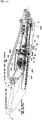
- FIG. 1 to FIGs. 6 are views illustrating a power seat slide device 1 according to a first embodiment of the present invention
- the power seat slide device 1 includes: a pair of left and right sliders 10, 10 arranged at a predetermined interval in a width direction of a seat cushion; a slide control mechanism 20; an electric mechanism 50; and so on, and it supports a cushion frame 100 of the seat cushion, and is capable of adjusting a position of the seat cushion.
- the sliders 10, 10 have a predetermined length, and include: lower rails 11, 11 fixed so that their longitudinal direction is along a front-rear direction of the seat cushion (cushion frame 100); and upper rails 12, 12 disposed to be movable along the longitudinal direction of the lower rails 11, 11.
- the lower rails 11, 11 and the upper rails 12, 12 of the respective sliders 10, 10 those whose sheet thickness is 1.8 mm or less are preferably used, and further those whose sheet thickness is in a range of 0.6 to 1.6 mm are preferably used.
- a material forming these one whose tensile strength is within a range of 400 to 590 MPa is preferably used. This is because only a small energy amount is required to work such a material and it can be formed by a relatively small press machine, which can contribute to a demand for energy saving and helps reduce manufacturing cost.
- lock mechanisms 13, 13 which fix relative positions of the upper rails 12, 12 to the lower rails 11, 11 are disposed on both sides of each of the upper rails 12, 12 as illustrated in FIG. 1 .
- the lock mechanisms 13, 13 have lock claws at their tips, and the lock claws are engaged with engaged parts formed in the lower rails 11, 11, and because the lock mechanisms 13, 13 are disposed on the both sides of each of the upper rails 12, 12, a posture in the engaged state and a direction in which an engagement force works become substantially laterally symmetric, so that an unbalanced load is not likely to occur at the time of locking.
- the left and right lock mechanisms 13, 13 in the pair of left and right sliders 10, 10 disposed at a predetermine interval include release members 13b, 13b which pivot on shaft portions 13a, 13a to release the engaged state of the lock claws, and include plate-shaped members 13c, 13c with a predetermined length hanging down from the left and right shaft portions 13a, 13a, and a coupling rod 13d is suspended between the plate-shaped members 13c, 13c. That is, operating the coupling rod 13d causes the release members 13b, 13b to pivot to release the four lock mechanisms 13, 13 in synchronization.
- the coupling rod 13d is disposed via the plate-shaped members 13c, 13c hanging down from the shaft portions 13a, 13a, and this is because side frames 110 of the cushion frame 100 are supported in a suspended manner by the upper rails 12 via a later-described link mechanism 25 in order to set a hip point of the seat cushion low.
- the lock mechanisms 13 include elastic lock members 130 and the release members 13b.
- the elastic lock members 130 include: attachment plate parts 131 which are formed of elastic members, typically, spring steel (flat springs) and fixed to the upper rails 12, 12; and operating plate parts 132 which are supported on the attachment plate parts 131, have elastic forces with which they are constantly biased in directions away from vertical wall parts 12a, 12a of the upper rails 12, 12, and include the lock claws 133 protruding in the directions away from the vertical wall parts 12a, 12a and engaged with the plural engaged parts which are formed along the longitudinal direction in facing portions in the lower rails 11, 11.
- the release members 13b displace the operating plate parts 132 in directions of the vertical plate parts 12a, 12a of the upper rails 12, 12 against the elastic forces of the operating plate parts 132 to release the engaged state between the lock claws 133 and the engaged parts of the lower rails 11, 11.
- the attachment plate parts 131 of the elastic lock members 130 have a shape along the vertical wall parts 12a, 12a of the upper rails 12, 12, and are fixed by rivets or the like.
- the operating plate parts 132 are integrated with the attachment plate parts 131, and are bent from upper edges of the attachment plate parts 131 in the directions opposite the vertical wall parts 12a, 12a of the upper rails 12, 12 and downward. Further, the operating plate parts 132 have, in the middle, bulging portions 132a bulging in the directions away from the vertical wall parts 12a, 12a of the upper rails 12, 12.
- the lock claws 133 are formed in a comb teeth shape in such a manner that the vicinities of lower edges of the operating plate parts 132 under the bulging portions 132a are folded so as to project in the directions away from the vertical wall parts 12a, 12a.
- the attachment plate parts 131 included in the elastic lock members 130 are preferably disposed at substantially longitudinal-direction center portions of the upper rails 12, 12.
- a reason for this is that elasticity of the elastic lock members 130 act on the upper rails 12, 12 and the lower rails 11, 11, so that the lower rails 11, 11 and the upper rails 12, 12 are practically elastically deformable to be given a function of, for example, absorbing energy ascribable to vibration and an impact force, and the above arrangement can make this function exhibited more efficiently.
- the release members 13b are disposed so that, about their one end portions, their other end sides pivot up and down, and when they come into contact with the bulging portions 132a in an attempt to pivot along outer surfaces of the operating plate parts 132, the bulging portions 132a are displaced in the directions of the vertical wall parts 12a, 12a. Consequently, the lock claws 133 displace in the directions of the vertical wall parts 12a, 12a, so that the engaged state is released.
- the one end portions of the release members 13b that is, the totally four release members 13b are coupled by the coupling rod 13d suspended between the left and right upper rails 12, 12 as described above. Therefore, operating an operation part (not illustrated) coupled to either side of the coupling rod 13d causes the synchronous operation of the four lock release members to release the lock.
- downward tilting wall parts 114, 114 extend, being bent obliquely downward, and the aforesaid engaged parts 114a, 114a of the lower rails 11, 11 are formed as a plurality of holes or grooves which are formed in the downward tilting wall parts 114, 114 along the longitudinal direction at intervals conforming to intervals between the adjacent claws of the lock claws 133 in the comb teeth shape (refer to FIG. 7 ).
- the upper rails 12, 12 each have a substantially T-shaped cross section, and on horizontal wall parts 122, 122 corresponding to positions of horizontal lines of the character "T", upward tilting wall parts 123, 123 rising obliquely from outer edge portions toward the vertical wall parts 12a are formed, and the upward tilting wall parts 123, 123 are disposed so as to be located on outer sides of the downward tilting wall parts 114, 114 of the lower rails 11, 11.
- auxiliary engaged parts 123a, 123a being holes or grooves are formed at positions corresponding to the formation positions of the lock claws 133 (refer to FIG. 3 , FIG.
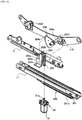
- the slide control mechanism 20 includes a rack 21, a pinion 22, an up-down movement relay gear 23, a lift gear 24, the link mechanism 25, and an elastic member 26.
- the slide control mechanism 20 of this embodiment not only enables front-rear slide operation by the rack 21 and the pinion 22, but also enables up-down movement by the up-down movement relay gear 23, the lift gear 24, the link mechanism 25, and the elastic member 26, and it is configured to not only control the front-rear slide operation but also function as a slider-lifter interlocking mechanism which enables the up-down movement in accordance with the slide operation.
- the rack 21 is fixed to an outer side surface of the lower frame 11 included in one of the left and right sliders 10, 10, in this embodiment, the slider 10 corresponding to a right side of the seat cushion. Further, since, in the mechanism in this embodiment, later-described front links 251, 251 of the link mechanism 25 are pivoted to cause the up-down movement of front edge sides of the side frames 110 of the cushion frame 100 and rear links 252, 252 are made to follow this movement, the rack 21 is disposed from the vicinity of a longitudinal-direction center to a front end side of the lower frame 11. Further, teeth 21a of the rack 21 are formed on an upper surface of the rack 21 so as to be directed upward as illustrated in FIG. 2 to FIG. 6 , and the height of the rack 21 is set so that its teeth 21a are located at a lower height than the upper surface of the lower rail 11.
- the pinion 22 is disposed on a side surface on the same side as the rack 21 disposed on the lower rail 11, is fit around a shaft part 22a which penetrates through the vertical wall part of the upper rail 12 in a thickness direction to be supported, and is disposed so as to have its peripheral teeth 22b meshed with the teeth 21a of the rack 21. Since the height of the teeth 21a of the rack 21 is lower than the upper surface of the lower rail 11, a range of a height difference therebetween includes a part of the pinion 22 in terms of a diameter direction. Therefore, a part, of the pinion 22, protruding above the upper surface of the upper rail 12 is shorter than the diameter of the pinion 22, which is suitable for supporting the cushion frame 100 at a lower position.
- the up-down movement relay gear 23 for enabling the up-down movement is formed of a gear (spur gear) smaller in diameter than the pinion 22, and is supported coaxially with the pinion 22, that is, on the shaft part 22a. Therefore, when the pinion 22 rotates in mesh with the rack 21, the spur gear being the up-down movement relay gear 23 also rotates together with the pinion 22.
- the lift gear 24 is formed of a fan-shaped plate member and has, near its peripheral surface, an arc-shaped hole part 24a, and the arc-shaped hole part 24a has an arc-shaped teeth 24b on its inner peripheral surface.
- the arc-shaped teeth 24b are meshed with the spur gear being the up-down movement relay gear 23.
- One end portion of a power transmission shaft 24c is coupled to a position near the center of the arc of the arc-shaped teeth 24b of the lift gear 24 (that is the vicinity of the center of the fan-shaped plate member).
- the cushion frame 100 being a skeletal frame of the seat cushion includes: the pair of left and right side frames 110, 110 disposed at a predetermined interval; and a plurality of pipe members 121 to 123 disposed between the pair of left and right side frames 110, 110 at a front edge side, a rear edge side, and a position therebetween respectively.
- the width of the cushion frame 100 that is, the interval between the pair of left and right side frames 110, 110 is set narrower than an interval between the lower frames 11, 11 of the pair of left and right sliders 10, 10. This enables the cushion frame 100 to be supported by the upper rails 12, 12 in a suspended manner.
- the side frames 110, 110 are in a shape having center plate parts 110a, 110a, front plate parts 110b, 110b extending ahead obliquely upward from the center plate parts 110a, 110a, and rear plate parts 110c, 110c extending aback obliquely upward from the center plate parts 110a, 110a (refer to FIG. 3 ).
- This shape is intended to make a cushioning member supported on the cushion frame have a predetermined shape when it is placed.
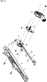
- the link mechanism 25 includes: the pair of left and right front links 251, 251; and the pair of left and right rear links 252, 252 disposed so as to be apart rearward from the front links 251, 251 along the longitudinal direction of the upper rails 12, 12 and the side frames 110, 110.
- the front link 251 corresponding to a width-direction right side of the seat cushion has an upper portion coupled to the other end portion of the power transmission shaft 24c.
- the power transmission shaft 24c is disposed so as to be inserted to a shaft bearing cylinder part 12a which is disposed in the thickness direction of the upper rail 12 near a front end of the upper rail 12, the vicinity of the center of the lift gear 24 is coupled to one end portion being an outer end side of the power transmission shaft 24c, and the upper portion of the right front link 251 is coupled to the other end portion being its inner end side.
- a lower portion of the right front link 251 is pivotally supported on the vicinity of a boundary between the front plate part 110b and the center plate part 110a of the right side frame 110 via a bracket 251a.
- the left front link 251 has an upper portion and a lower portion pivotally supported on the left upper rail 12 and on the vicinity of a boundary between the front plate part 110b and the center plate part 110a of the left side frame 110 via brackets 251b, 251c respectively.
- the rear links 252, 252 both have upper portions pivotally supported on rear portions of the left and right upper rails 12 via brackets 252a, 252a respectively, and have lower portions pivotally supported on the vicinities of boundaries between the rear plate parts 110c, 110c and the center plate parts 110a, 110a of the side frames 110 via brackets 252b, 252b respectively.
- the front links 251, 251 and the rear links 252, 252 both have the upper portions pivotally supported on the upper rails 12, 12 side and have the lower portions pivotally supported on the side frames 110, 110 sides of the cushion frame 100, so that the cushion frame 100 is supported in a suspended manner by the upper rails 12, 12 via the link mechanism 25.
- Postures of the front links 251, 251 and the rear links 252, 252 at lower limit positions are both closer to vertical postures as illustrated in FIG. 6(a)
- their postures at upper limit positions are closer to horizontal postures as illustrated in FIG. 6(b)
- a height-direction displacement amount between the lower limit position and the upper limit position of the front links 251, 251 is set smaller as compared with a height-direction displacement amount of the rear links 252, 252.
- the front links 251, 251 those shorter than the rear links 252, 252 are used, and at the lower limit position (when the upper rails 12, 12 are at the rear end position), in the side view, the front links 251 251 are disposed so as to have the vertical posture or a tilting posture relatively to the vertical posture with their lower portions being a little more forward than their upper portions, and the rear links 252, 252 are disposed so as to have a tilting posture relatively to the vertical posture with their lower portions being more rearward than their upper portions (refer to FIG. 6(a) ), so that the aforesaid difference in the displacement amount occurs.
- the seat cushion in a state where the cushioning member is disposed on the cushion frame 100 has a smaller seating surface angle (line indicated by the reference sign "P" in FIG. 2 ) at the upper limit positions (when the upper rails 12, 12 are at the front end position) than its seating surface angle (line indicated by the reference sign "Q” in FIG. 2 ) at the lower limit position (when the upper rails 12, 12 are at the rear end position).
- the difference between the seating surface angle (the line indicated by the reference sign "Q" in FIG. 2 ) of the seat cushion at the lower limit position (when the upper rails 12, 12 are at the rear end position) and its seating surface angle (the line indicated by the reference sign "P" in FIG. 2 ) at the upper limit position (when the upper rails 12, 12 are the front end position) is preferably within a range of about 3 to 8 degrees.
- the elastic member 26 biases the cushion frame 100 forming the seat cushion in an ascending direction and applies a force for lifting up the cushion frame 100.
- the elastic member 26 may be any, provided that it achieves such a function.
- a spiral spring is used as the elastic member 26, and its inner end portion 26a is fit in a slit 24d incised in the other end portion being the inner end side of the power transmission shaft 24c.
- a support shaft 12c is protrudingly disposed, and an outer end portion 26b of the spiral spring is fit on the support shaft 12c.
- the elastic member 26 is disposed between the side frame 110 and the upper rail 12. Since elasticity of the spiral spring constantly acts in a spreading direction, the side frame 110 is biased in the ascending direction relatively to the upper rail 12.
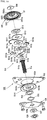
- the electric mechanism 50 includes a motor 51.
- the electric mechanism 50 is composed only of the motor 51, and a drive shaft 51a of the motor 51 is coupled so as to be capable of rotating the pinion 22.
- the "drive shaft 51a” is a shaft which transmits a torque of the motor 51, and what it means includes not only a shaft directly connected to a main body of the motor 51 as in FIG. 3 but also a shaft which transmits the torque to another member (for example, a clutch 53) via a gearbox 51b as illustrated in FIG. 5 and so on which will be described later.
- the motor 51 rotates, its torque rotates the pinion 22 via the drive shaft 51a, or via an appropriate gear mechanism as required.
- the pinion 22 moves in, for example, a forward rolling direction relatively to the rack 21, but since the pinion 22 is attached to the upper rail 12 via the shaft part 22a, the forward rolling of the pinion 22 causes the upper rails 12, 12 relatively to the lower rails 11, 11 to move forward together with the pinion 22.
- the torque of the motor 51 is transmitted to the pinion 22 while the motor 51 is energized, whether the torque is in the forward direction or the reverse direction, but when a power source of the motor 51 is in a non-energized state and the lock mechanisms 13 are in the lock release mode, a force input from the pinion 22 side rotates the drive shaft 51a.
- the seat cushion including the cushion frame 100 and the cushioning member and so on disposed on the upper portion of the cushion frame 100 try to move either forward or rearward.
- the upper rails 12, 12 of the sliders 10, 10 are coupled to the side frames 110, 110 of the cushion frame 100 forming the seat cushion, the upper rails 12, 12 move in the forward or rearward direction relatively to the lower rails 11, 11. Consequently, even when the engine is off or in the non-energized state due to an accident or the like, it is possible to manually slide the upper rails 12, 12 forward and rearward relatively to the lower rails 11, 11.
- the pinion 22 in the above case of the manual front-rear movement, the pinion 22 also rotates forward or rearward, and its torque rotates the drive shaft 51a of the motor 51.
- the rotation of the drive shaft 51a causes a rotor to rotate relatively to a stator in the motor 51, so that an electromagnetic force is generated.
- This electromagnetic force damps the torque of the drive shaft 51a and also damps the torque of the pinion 22 coupled to the drive shaft 51a, so that the moving operation of the upper rails 12, 12 in the front-rear direction becomes slow as compared with a case where a damping force does not act. That is, the motor 51 functions as a damper utilizing the electromagnetic force.
- a switch for changing to the electric mode can be disposed on the coupling rod 13d of the lock mechanisms 13.
- the coupling rod 13d is rotated by an operation lever and the lock is released by the release members 13b.
- adoptable is a structure in which the switch of the motor 51 turns on when the coupling rod 13d is rotated to reach a predetermined position.
- the lock mechanisms 13 are disposed on both sides of each of the upper rails 12, 12, the lock is enabled by the lock mechanisms 13 being engaged with the lower rails 11, 11, and the motor is actuated in conjunction with the release operation of the lock mechanisms 13 to rotate the pinion 22 disposed along the lower rail 11, 11, so that the upper rails 12, 12 move forward or rearward along the lower rails 11, 11.
- the lock mechanisms 13 are disposed on the both sides of each of the upper rails 12, 12, and in addition, they have the laterally well-balanced structure as described above, they serve as strength members, which eliminates a need for slide screws as the strength members which have been necessary in a conventional power seat slide device.
- the front-rear movement is enabled by the aforesaid manual operation during the non-energized period.
- the lock claws 133 are engaged with the engaged parts 114a, 114a which are disposed in the lower rails 11, 11 at predetermined intervals, whereby the locked state is produced as described above.
- the front-rear movement is electrically caused in this embodiment, the operation surely continues up to the lock position, and what is called half-lock is not caused in the electric mode.
- the electric mechanism 50 may be composed of the motor 51 with a simple structure not including a speed reducer as illustrated in FIG. 3 , or may be composed of a geared motor integrally including the speed reducer (gearbox 51b) as illustrated in FIG. 4 .
- the electric mechanism 50 is composed of the geared motor, since the gearbox 51b is integrally included, it is possible in the electric mode to appropriately adjust the speed of the front-rear position adjustment or the like by the sliders 10, depending on the selection of the gear.
- FIG. 5 illustrates an example where the electric mechanism 50 is configured to further have the clutch 53 in addition to the motor 51 with the gearbox 51b.
- the gearbox 51b appropriately adjusts the speed of the front-rear position adjustment by the sliders 10 and the speed of the up-down position adjustment by the lifter 20, depending on the selection of the gear.
- the driving force of the motor 51 is appropriately reduced in speed by the gearbox 51b and then rotates the drive shaft 51a.
- the drive shaft 51a of the motor 51 is coupled to an input side of the clutch 53, and the torque of the motor 51 is transmitted to the clutch 53 via the drive shaft 51a.
- an input shaft 53b for pinion is disposed, and the pinion 22 rotates by the input shaft 53b for pinion being coupled to a rotation center of the pinion 22.
- the torque of the motor 51 is transmitted to the pinion 22 via the clutch 53. Therefore, when the motor 51 is in the energized state, the torque of the motor 51 is transmitted to the pinion 22 via the clutch 53, whether the torque is in the forward direction or the reverse direction, but when the motor 51 is in the non-energized state, since the clutch 53 enters a cut-off mode, the torque is not transmitted from the pinion 22 side to the motor 51.
- the use as the manual mechanism as described above is of course possible when the motor 51 is in the non-energized state, but in this case, the damping force of the motor 51 does not function. Therefore, the aforesaid manual adjustment is performed without the movement of the upper rails 12, 12 being buffered.
- a separate damper such as an oil damper is disposed.
- the above-described example using the damping force of the motor 51 is more preferable because it contributes to structure simplification and cost reduction.
- the operation when the cushion frame 100 makes the up-down movement in conjunction with the front-rear movement of the upper rails 12, 12 by the operation of the slide control mechanism 20 will be described. It is assumed that, in the sliders 10, 10, the upper rails 12, 12 are located at the rear ends of the lower rails 11, 11 as illustrated in FIG. 6(a) .
- the front links 251, 251 have the vertical posture or the posture tilting relatively to the vertical state with their lower portion sides being slightly forward.
- the rear links 252, 252 have the posture tilting relatively to the vertical state, with their lower portion sides being slightly rearward.
- the seat cushion including the cushion frame 100 and the cushioning member and so on disposed on the upper portion of the cushion frame 100 try to move forward.
- the upper rails 12, 12 move forward (direction of the arrow (A) in FIG. 2 ) relatively to the lower rails 11, 11 since the upper rails 12, 12 of the sliders 10, 10 are coupled to the side frames 110, 110 of the cushion frame 100 forming the seat cushion.
- the pinion 22 pivotally supported on the right upper rail 12 in this embodiment rolls forward (rolls in the direction of the arrow (B) in FIG. 2 ) along the longitudinal direction of the rack 21 since the teeth 22b of the pinion 22 are in mesh with the teeth 21a of the rack 21. Consequently, the up-down movement relay gear 23 supported on the shaft part 22a of the pinion 22 also rolls forward.
- the lift gear 24 in mesh with the up-down movement relay gear 23 rotates.
- the lift gear 24 is set so that the up-down movement relay gear 23 is located at the uppermost side of the arc-shaped teeth 24b while being in mesh therewith, when the upper rails 12 exist at the rear end position as illustrated in FIG.
- the upper portion of the right front link 251 pivots forward (anticlockwise in FIG. 2 and FIG. 6 (the direction of the arrow (D) in FIG. 2 )), with the lower portion pivotally supported on the right side frame 110 serving as a fulcrum.
- the left front link 251 is only pivotally supported between the left upper rail 12 and side frame 110, and therefore its upper portion pivots forward with its lower portion serving as a fulcrum, in synchronization with the movement of the right front link 251.
- the rear links 252, 252 are both only pivotally supported between the upper rails 12, 12 and the side frames 110, 110, and therefore follow the movement of the front links 251, 251.
- the rear links 252, 252 when the upper rails 12, 12 exist at the rear end positions of the lower rails 11, 11, the rear links 252, 252 have the posture tilting relatively to the vertical posture at a slight angle with their lower portions being rearward (refer to FIG. 6(a) ), but the lower portions further pivot anticlockwise (direction of the arrow (E) in FIG. 2 ) when the upper rails 12, 12 move forward, so that the rear links 252, 252 become more horizontal (refer to FIG. 6(b) ).
- FIG. 6(b) illustrates a state where the upper rails 12, 12 are located at the front ends of the lower rails 11, 11, and as illustrated in this drawing, the front links 251, 251 and the rear links 252, 252 all displace anticlockwise in the drawing, that is, in a direction in which they come to have postures closer to the horizontal postures, as compared with the case where the the upper rails 12, 12 are at the rear end positions as in FIG. 6(a) .
- a height difference of the lower portions of the front links 251, 251 is an up-down direction displacement amount of the vicinities of the boundaries between the center plate parts 110a, 110a and the front plate parts 110b, 110b of the side frames 110, 110 on which the front links 251, 251 are pivotally supported
- a height difference of the lower portions of the rear links 252, 252 is an up-down direction displacement amount of the vicinities of the boundaries between the center plate parts 110a, 110a and the rear plate parts 110c, 110c of the side frames 110, 110 on which the rear links 252, 252 are pivotally supported.
- the seating surface angle in the case of the front end and the upper limit position illustrated in FIG. 6(b) is smaller than in the case of the rear end and the lower limit position illustrated in FIG. 6(a) (refer to FIG. 2 ).
- the elastic member 26 formed of the spiral spring is disposed between the right upper rail 12 and side frame 110 as described above, and therefore, when the lift gear 24 pivots anticlockwise in FIG. 2 and FIG. 6 , its torque is assisted, so that the cushion frame 100 can be easily lifted up.
- the front-rear slide operation and the up-down movement are interlocked in this embodiment, and therefore, when the pinion 22 rolls forward, the up-down movement relay gear 23 formed of a worm also rolls in the same direction to pivot the lift gear 24 on the power transmission shaft 24c and displace the pair of front links 251, 251 and the pair of rear links 252, 252 of the link mechanism 25 in the direction in which the positions of their lower portions become higher, so that the cushion frame 100 is lifted up.
- the motor 51 rotates in the direction opposite the above, the drive shaft 51a, the pinion 22, the up-down movement relay gear 23, and the lift gear 24 all rotate in the direction opposite the above, so that the cushion frame 100 is lowered.
- FIG. 9 to FIG. 13 are views illustrating a power seat slide device 1 according to a second embodiment of the present invention, and this power seat slide device 1 is different from that of the above-described first embodiment in the structure of a slide control mechanism 200, but the other structure is completely the same.
- the slide control mechanism 200 is the same as the slide control mechanism 20 of the above-described first embodiment in that it includes a rack 201, a pinion 202, an up-down movement relay gear 203, a lift gear 204, a link mechanism 205, and an elastic member 206, but is different in the structures of the rack 201, the pinion 202, the up-down movement relay gear 203, and the lift gear 204. Therefore, what are different are mainly described in the below.
- the rack 201 is the same as that of the above-described first embodiment in that it is disposed along an outer side surface of one of lower rails 11 (in this embodiment, a width-direction right side of a seat cushion), but in this embodiment, it is attached so that its teeth 201a protrude outward from a bottom surface of the lower rail 11, that is, its teeth 201a are directed horizontally in a plane view (refer to FIG. 11 ).
- the pinion 202 is disposed so as to rotate in a substantially horizontal direction while being in mesh with the horizontally directed teeth 201a of the rack 201.
- the up-down movement relay gear 203 is formed of a worm disposed along a direction substantially perpendicular to a longitudinal direction of a slider 10.
- An attachment bracket 203a is disposed at a position closer to a front edge end than a longitudinal-direction center portion of one of upper rails 12, and an upper end portion and a lower end portion of the up-down movement relay gear 203 formed of the worm are supported on arms 203b, 203b which are disposed on both end portions of the bracket 203a so as to project forward.
- the up-down movement relay gear 203 formed of the worm is disposed along an up-down direction substantially perpendicular to the longitudinal direction of the upper rail 12 and is rotatable in a circumferential direction.
- the aforesaid pinion 202 is attached to the lower end portion 203d of the up-down movement relay gear 203 formed of the worm.
- the lift gear 204 is formed of a worm wheel in a substantially fan shape meshed with the up-down movement relay gear 203 formed of the worm, and one end of a power transmission shaft 204c is coupled to a rotation center of the lift gear 204 as in the above-described first embodiment.
- the other end of the power transmission shaft 204c is coupled to one of front links 2051 of a link mechanism 205 as in the above-described embodiment.
- the link mechanism 205 includes the pair of front links 2051, 2051 and a pair of rear links 2052, 2052 is the same as in the above-described first embodiment, and further the structure of an elastic member 206 formed of a spiral spring is also the same as that of the above-described first embodiment.
- This embodiment is set in such a manner that, in order for the cushion frame 100 to be at a lower limit position when the upper rails 12, 12 are at a rear end position, teeth of the lift gear 204 near an upper end, out of its arc-shaped teeth 204b, are meshed with the vicinity of an upper end of the up-down movement relay gear 203 formed of the worm.
- the pinion 202 in mesh with the teeth 201a of the rack gear 201 rotates anticlockwise (the direction of the arrow (B) in FIG. 10 ) in a plane view.
- the up-down movement relay gear 203 formed of the worm also rotates anticlockwise (the direction of the arrow (B) in FIG. 10 ) in a plane view.
- the lift gear 204 whose arc-shaped teeth 204b are in mesh with the up-down movement relay gear 203 pivots anticlockwise in FIG. 8 (the direction of the arrow (C) in FIG. 10 ) about the power transmission shaft 204c.
- the worm is adopted as the up-down movement relay gear 203
- the worm wheel is adopted as the lift gear 204. Accordingly, since a self-lock function of a worm gear mechanism works, an input from a seat cushion side including the cushion frame 100 does not rotate the up-down movement relay gear 203 formed of the worm via the lift gear 204 formed of the worm wheel, which hinders the transmission of the force to the sliders 10, 10. Therefore, at the time of lock release of the sliders 10, 10 by lock mechanisms 13, 13, it is possible to prevent unintentional actuation ascribable to elasticity of the elastic member 26.
- an electric mechanism 50 in this embodiment is also the same as that of the above-described first embodiment. That is, in FIG. 11 , a motor 51 is used as the electric mechanism 50, and its drive shaft 51a is coupled to a rotation shaft of the pinion 202. Therefore, when the motor 51 is in an energized state, the use in an electric mode is possible, and when the motor 51 is in a non-energized state, the upper rails 12, 12 can be manually moved forward and rearward. Incidentally, at the time of the manual front-rear movement in the non-energized state, the drive shaft 51a side of the motor 51 rotates, and an electromagnetic force generated by this can suppress the rotation of the pinion 202 and the movement of the upper rails 12, 12. This point is the same as in the example illustrated in FIG. 1 to FIG. 4 where the clutch 53 is not adopted, in the above-described embodiment.
- FIG. 12 illustrates a structure when a motor 51 formed of a geared motor with which a gearbox 51b is integrated is used as the electric mechanism 50
- FIG. 13 illustrates a structure in which one further having a clutch 53 in addition to the motor 51 and the gearbox 51b is used as the electric mechanism 50, and their operation and effect are the same as those in the examples illustrated in FIG. 4 and FIG. 5 in the above-described first embodiment.
- the front-rear position adjustment, the height adjustment, and the seating surface angle adjustment of the seat cushion including the cushion frame 100 can be performed in conjunction with a single operation of the lock release operation of the sliders 10, 10 by the lock mechanisms 13, 13, but it goes without saying that the power seat slide device having the structure capable of operating both in the electric mode and the manual mode is applicable to a case where only a front-rear position adjustment mechanism is provided without an interlocking mechanism with the lifter, that is, to a case where it only moves the upper rails 12, 12 forward and rearward relatively to the lower rails 11, 11.
- FIG. 14 to FIG. 16 are views illustrating a third embodiment of the present invention, and this embodiment illustrates an example where lower rails 11, 11 are disposed on a floor of a vehicle at a tilt angle, with their front ends being higher and their rear ends being lower.
- the front-rear position adjustment mechanism and the up-down position adjustment mechanism are interlocked, but it is optional whether or not they are interlocked, and a slide control mechanism 2000 of this embodiment functions only as a front-rear position adjustment mechanism, and is formed independently of an up-down position adjustment mechanism. Therefore, there are provided a motor 510 for the up-down position adjustment mechanism and a motor 520 for a tilt angle adjustment mechanism, separately from a motor 51 for the front-rear position adjustment mechanism.
- a rack 2100 is disposed on one of lower rails 11, which is the same as in the above-described embodiments, but in this embodiment, in the rack 2100, a long hole 2110 extending in its longitudinal direction is formed as illustrated in FIG. 15(a) . Teeth 2111 are incised on an upper edge of the long hole 2110. That is, the teeth 2111 of the rack 2100 are formed to be directed downward, unlike the above-described embodiments.
- the rack 2100 is formed to have a substantially L-shaped cross section and is attached to a side surface of the lower rail 11. More specifically, since it is formed in the substantially L shape, there is a gap 2112 between its surface in which the long hole 2110 is formed and the side surface of the lower rail 11, and a pinion 2200 is disposed so as to be inserted in the long hole 2110 and be in mesh with the teeth 2111.
- a gearbox 51b is attached to the motor 51, the pinion 2200 is attached to its output shaft, and the pinion 2200 rotates in accordance with the rotation of the motor 51.
- an operation lever 1300 is coupled to a shaft part 13a of a release member 13b of a lock mechanism 13, and when the operation lever 1300 is operated, the release member 13b pivots to cause lock release.
- a switch lever 1310 is disposed which also pivots about the shaft portion 13a at this time and moves in synchronization with the operation lever 1300.
- a slide switch 1320 which controls on/off of the motor 51 is disposed at a position corresponding to the switch lever 1310, and when the switch lever 1310 pivots up and down, the slide switch 1320 is turned on and off.
- This embodiment is set so that, when the operation lever 1300 is at the locked state position of the lock mechanism 13, the switch lever 1310 is located at a position where it keeps the slide switch 1320 in the off state, and when the operation lever 1300 is moved up or down, the lock of the lock mechanisms 13 is released whether the movement is in the upward direction or the downward direction, and when the switch lever 1310 moves up or down in accordance with this, the slide switch 1320 turns on whether the movement is in the upward direction or the downward direction, so that the motor 51 is driven.
- This embodiment is set so that, when the operation lever 1300 and the switch lever 1310 are moved up, the motor 51 is driven to rotate in such a direction as to move the upper rails 12 rearward relatively to the lower rails 11, and when the operation lever 1300 and the switch lever 1310 are operated downward, the motor 51 is driven to rotate in such a direction as to move the upper rails 12 forward relatively to the lower rails 11.
- the setting may be made in an opposite way.
- This control circuit 1330 is, as illustrated in FIG. 16(a) , is formed of a parallel circuit disposed between a power source 1340 of the vehicle and the motor 51 and composed of a diode 1331 being a rectifying element and a resistor 1332, and is set so as to be forward biased when a current which has passed through the motor 51 flows in the diode 1331, and a direction in which the current flows to the control circuit 1330 is changed by the aforesaid slide switch 1320.
- the slide switch 1320 when the operation lever 1300 is operated in the downward direction, the slide switch 1320 performs the switching so as to rotate the motor 51 in one direction. At this time, as indicated by the arrows in FIG. 16(b) , the direction of the current is switched so that the current flows in the motor 51 side first before flowing in the control circuit 1330. When the current flows first in the motor 51, the forward bias is produced, so that the current flows via the diode 1331 and performs the forward operation with a predetermined current value.
- the slide switch 1320 performs the switching so as to rotate the motor 51 in the opposite direction.
- the current flows first in the control circuit 1330 side as indicated by the arrows in FIG. 16(c) . Therefore, the diode 1331 is reverse-biased, and the current flows in the resistor 1332 and thereafter is supplied to the motor 51. Therefore, at the time of the rearward movement, the current value decreases to reduce the operation speed.
- the aforesaid control circuit 1330 controls the current supply in the rearward movement direction and as a result the operation speeds of the forward movement and the rearward movement can be stabilized at a substantially equal value.
- FIG. 17 to FIG. 21 are views illustrating essential parts of a fourth embodiment of the present invention.
- This embodiment is characterized in adopting a clutch 530 with a new structure.
- the clutch 530 is configured to transmit a torque from a motor 51 side to a pinion 22 side, whether the torque is in a forward direction or a rearward direction, but not to transmit a torque from the pinion 22 side (input counter torque) to the motor 51 side in a manual mode being a non-energized state.
- a drive shaft 51a of the motor 51 and the pinion 22 are coupled to an input side and an output side of the clutch 530 respectively.
- the clutch 530 includes an input-side torque transmitting member 531 and an output-side torque transmitting member 532 as illustrated in FIG. 18 .
- the input-side rotation transmitting member 531 includes a cam 5311 and a plurality of, in this embodiment, two plates 5312, 5312.
- the cam 5311 is formed in a plate shape and is formed to have a contour in a substantially elliptic shape in a plane view. Then, a fitting hole 5311a penetrating through the center of the cam 5311 and having, on its inner peripheral surface, two flat surfaces for rotation stop is formed, and this fitting hole 5311a is fit to portions corresponding to flat surfaces 511b formed at a tip side of the drive shaft 51a of the motor 51. Therefore, when the drive shaft 51a of the motor 51 rotates in either of forward and inverse directions, the cam 5311 also rotates.
- the cam 5311 has cam-side tapered surfaces 5311b, 5311b formed on its outer peripheral surfaces facing each other in a major axis direction.
- the cam-side tapered surfaces 5311b are formed in a valley-like groove shape in a plane view, on the peripheral surfaces, of the substantially elliptic cam 5311, which face each other in the major axis direction.
- the two plates 5312, 5312 are each formed of a plate-shaped member similarly to the cam 5311, and in this embodiment, are disposed across the major axis of the cam 5311. Outer peripheral surfaces of the plates 5312, 5312 are formed in a substantially arc shape and have input-side teeth parts 5312a, 5312a incised therein. On the other hand, on inner peripheral surfaces of the plates 5312, 5312, plate-side tapered surfaces 5312b, 5312b in a mountain shape in a plane view are formed in this embodiment. The plate-side tapered surfaces 5312b, 5312b in the mountain shape are formed so that their slopes and slopes of the cam-side tapered surfaces 5311b, 5311b in the valley shape of the cam 5311 can face each other.
- the both are in the deepest engagement state, which is a state where the distance between the input-side teeth part 5312a formed on the outer peripheral surface of one of the plates 5312 and the input-side teeth part 5312a formed on the outer peripheral surface of the other plate 5312 is shortest. Therefore, when the cam 5311 rotates even slightly from this state to either the left or the right, the distance between the facing input-side teeth parts 5312a, 5312a becomes longer. That is, the rotation of the cam 5311, whether it is in the left direction or the right direction, displaces the plates 5312, 5312 in a radial direction.
- retainer members 5313, 5313 are disposed in front of and at the back of the cam 5311 and the plates 5312, 5312 in terms of an axial direction, that is, disposed in both directions across the cam 5311 and the plates 5312, 5312, and the plates 5312, 5312 are retained between the pair of retainer members 5313, 5313 so as to be displaceable in the radial direction.
- the reference sign 5314 denotes a spacer disposed between one of the retainer members 5313, and the cam 5311 and the plates 5312, 5312, and the reference sign 5315 denotes a push nut disposed between this retainer member 5313 and an inner surface of the later-described output-side rotation transmitting member 532.
- the drive shaft 51a of the motor 51 has a large-diameter portion 511a in the middle, and on a peripheral surface closer to an axial-direction tip side (pinion 22 side) than the large-diameter portion 511a, the flat surfaces 511b for rotation stop are formed as described above.
- the retainer members 5313, the fitting hole 5311a of the cam 5311, the spacer 5314, and the other retainer member 5313 are fit, and they are retained by the push nut 5315 between the large-diameter portion 511a and the output-side rotation transmitting member 532.
- the input-side rotation transmitting member 531 has a plate guide member 5316 on whose one surface a pair of guide pieces 5316a, 5316a guiding the radial-direction displacement of the plates 5312, 5312 are disposed to stand.
- the pair of guide pieces 5316a, 5316a are formed in a semicircular shape at positions outside the outside diameter of the cam 5311, and are disposed so that the plates 5312, 5312 are located in a gap therebetween. Consequently, side surfaces of the plates 5312, 5312 are restricted by edges of the pair of guide pieces 5316a, 5316a to be guided in the radial direction.
- the reference sign 533 denotes an attachment bracket, and at its substantially center portion, a through hole 533a is formed.
- the aforesaid plate guide member 5316 On a surface, of the attachment bracket 533, located on the motor 51 side, the aforesaid plate guide member 5316 is disposed, its guide pieces 5316a, 5316a are disposed so as to protrude to the opposite surface side through the through hole 533a, and on this opposite surface side of the attachment bracket 533, the aforesaid cam 5311, plates 5312, 5312, and so on are disposed.
- the plate guide member 5316 is fixedly disposed between the attachment bracket 533 and a fixed plate 536 fixed to the motor 51-side surface of the attachment bracket 533 via a washer 534 and a wave washer 535. At a substantially center portion of the plate guide member 5316, a shaft insertion hole 5316b is formed, and the drive shaft 51a is disposed and inserted so that its large-diameter portion 511a is located in the shaft insertion hole 5316b.
- a portion, of the drive shaft 51a, closer to an axial-direction rear end (motor 51 side) than the large-diameter portion 511a passes through a shaft insertion hole 536a of the fixed plate 536 to be positioned by a washer 537 and a push nut 538, and is rotatably attached.
- the input-side rotation transmitting member 531 further has a biasing member 5317 which biases the pair of two plates 5312, 5312 in a direction in which they approach each other in the radial direction. That is, the biasing member 5317 is a spring formed of a wire member curved into a substantially semi-annular shape, and at its both end portions, engagement parts 5317a, 5317a having a shape bulging from an inner peripheral surface side toward an outer peripheral surface side are formed. The engagement parts 5317a, 5317a are engaged with pins 5312d, 5312d protrudingly disposed on one-side surfaces of the plates 5312, 5312.
- biasing member 5317 After the biasing member 5317 is radially stretched, its engagement parts 5317a, 5317a are engaged with the pins 5312d, 5312d, whereby the biasing member 5317 constantly biases, by its reactive force, the pair of two plates 5312, 5312 in the direction in which they approach each other in the radial direction.
- the output-side rotation transmitting member 532 has an annular part 5321 including, on its inner peripheral surface, an output-side teeth part 5321a meshable with the aforesaid input-side teeth parts 5312a, 5312a, and a housing part 5322 in a substantially concave sectional shape formed integrally on one side of the annular part 5321.
- a shaft bearing hole 5322a is penetratingly formed in an end wall of the housing part 5322.
- an internal gear is used, and its internal teeth are used as the output-side teeth part 5321a.
- the input-side rotation transmitting member 531 is disposed so that the cam 5311 and the plates 5312, 5312 are at a position corresponding to the annular part 5321, whereby the input-side teeth parts 5312a, 5312a become meshable with the output-side teeth part 5321a, and on the other hand, the input-side teeth parts 5312a, 5312a are normally apart from the output-side teeth part owing to an elastic force of the biasing member 5317. Further, the retainer members 5313, the push nut 5315, and so on of the input-side rotation transmitting member 531 are housed in the housing part 5322, the tip portion 511c of the drive shaft 51a penetrates through the shaft bearing hole 5322a to be supported by a retaining washer 539.
- the output-side rotation transmitting member 532 is disposed so that its torque is transmitted to the pinion 22 meshed with a rack 21 attached to a lower rail 11, and in this embodiment, the annular part 5321 of the output-side rotation transmitting member 532 has external teeth on its outer peripheral surface, and the external teeth themselves are used as the pinion 22 meshed with the rack 21.
- the use of the external teeth themselves as the pinion 22 is only an example, and it is also possible that another gear or the like is combined with the external teeth, a gear ratio is appropriately adjusted, and this structure is disposed so that the torque is transmitted to the pinion 22 formed of a member independent of the output-side rotation transmitting member 532 .
- the tip portion 511c is inserted from a through hole 15a of an upper rail attachment bracket 15, and the washer 539 is coupled to the tip portion 511c at an opposite surface side as illustrated in FIG. 17 . Consequently, the pinion 22 being the external teeth of the annular part 5321 (refer to FIG. 18 ) of the output-side rotation transmitting member 532 is meshed with the rack 21.
- a guide member 15b formed of a roller, a sliding member, or the like is disposed at a position which is on a lower portion of the upper rail attachment bracket 15 and at which it is abuttable on a surface, of the rack 21, where teeth 21a are not formed (in this embodiment, a lower surface 21d). Therefore, the rack 21 is sandwiched by the pinion 22 and the guide member 15b. Accordingly, when the upper rail 12 slides forward and rearward relatively to the lower rail 11, the guide member 15b moves while abutting on the lower surface 21d of the rack 21, which suppresses backlash between the pinion 22 and the rack 21 to make the movement of the pinion 22 smooth and accordingly also suppress the generation of noise.
- one end 21b of the rack 21 is fixed to the lower rail 11 and thus is a fixed end, and its other end 21c is a free end not fixed to the lower rail 11. Consequently, it is possible to absorb size variation of products such as the rack 21 and the pinion 22, which enables a stable operation and also contributes to the suppression of the generation of noise during the operation. Note that this point is the same also in a later-described structure where a lifter interlocking mechanism is provided (refer to FIG. 22 ).
- the pair of two plates 5312, 5312 are constantly biased by the biasing member 5317 in the direction in which they approach each other in the radial direction, and the plate-side tapered surfaces 5312b, 5312b in contact with the cam-side tapered surfaces 5311b, 5311b in the valley shape of the cam 5311 are in such a positional relation that the apex portions 5312c, 5312c of the plate-side tapered surfaces 5312a, 5312a face the bottom portions 5311c, 6311c of the grooves of the cam-side tapered surfaces 5311 b, 5311 b, as illustrated in FIG. 21(a) .
- the radial-direction distance between the input-side teeth part 5312a formed on the outer peripheral surface of one of the plates 5312 and the input-side teeth part 5312a formed on the outer peripheral surface of the other plate 5312 becomes shortest, and the input-side teeth parts 5312a, 5312a are out of mesh with the output-side teeth part 5321a of the output-side rotation transmitting member 532.
- the plate-side tapered surfaces 5312b, 5312b in contact with the cam-side tapered surfaces 5311b, 5311b are pressed toward the outer peripheral sides along the cam-side tapered surfaces 5311b, 5311b, and the plates 5312, 5312 move toward the outer peripheral sides while being guided by the guide pieces 5316a, 5316a of the plate guide member 5316, so that the distance between the input-side teeth parts 5312a, 5312a becomes longer.
- the input-side teeth parts 5312a, 5312a come into mesh with the output-side teeth part 5321a of the output-side rotation transmitting member 532.
- the output-side rotation transmitting member 532 rotates.
- the output-side rotation transmitting member 532 is connected so that its torque is transmitted to the pinion 22 as described above, and in this embodiment, since the external teeth formed on the output-side rotation transmitting member 532 are used as the pinion 22, the pinion 22 rotates in accordance with the rotation of the output-side rotation transmitting member 532. Since the pinion 22 is in mesh with the rack 21, the upper rails 12 move forward or rearward relatively to the lower rails 11 in the electric mode according to the rotation direction of the pinion 22, as in the above-described embodiments.
- the torque of the motor 51 does not act, but since the biasing member 5317 constantly biases the plates 5312, 5312 in the direction in which they approach each other in the radial direction as described above, the plates 5312, 5312 in the state where the torque of the motor 51 does not act return to the positional relation in FIG. 21(a) , and the input-side teeth parts 5312a, 5312a become out of mesh with the output-side teeth part 5321a.
- the clutch 530 of this embodiment thus transmits the torque from the input side, but cuts off the input counter torque from the output side without transmitting it.
- a clutch which cuts off the input counter torque is generally structured to have a roller disposed between an input outer ring and an output inner ring, a retainer retaining this roller, a centering spring for positioning the retainer, and so on as disclosed in, for example, Japanese Unexamined Patent Application Publication No. 2003-120715 .
- the input outer ring has, on its inner peripheral surface, a cam surface which forms a wedge clearance becoming narrower from a center position in a movable range of the roller symmetrically both in forward and reverse rotation directions, and when the roller is located at the center of the wedge clearance, there is a clearance between the roller and the output inner ring, so that the output inner ring is freely rotatable, so that a mode in which the input counter torque from the output side is not transmitted to the input outer ring is entered.
- the retainer rotates to press and shrink the centering spring, and the roller moves in a direction in which the wedge clearance becomes narrow, to penetrate in the wedge clearance against the elastic force of the centering spring, so that a mode in which the rotational torque input to the input outer ring is transmitted to the output inner ring via the roller is entered. Then, when the rotation operation of the input outer ring stops, the roller returns to the center position of the wedge clearance due to a restoring force of the centering spring.
- the centering spring which is designed according to the high shaft rotation speed of the input side is generally used for the positioning, but if the shaft rotation speed on the input side is low in such a positioning state, a spring force of the centering spring is strong to reduce the penetration amount of the roller, which sometimes causes a case where the torque on the input side is not smoothly transmitted to the output side. As a result, the movement is not sometimes stable at the time of the change between the mode in which the rotational torque on the input side is transmitted and the mode in which the rotational torque on the output side is cut off.
- the clutch 530 of this embodiment does not utilize the penetration of the roller in the rotation direction, but controls the meshed state and the non-meshed state between the input-side teeth parts 5312a, 5312a and the output-side teeth part 5321a, depending on the radial-direction movement of the plates 5312, 5312. Therefore, without relying on the shaft rotation speed on the input side, a speedily responsive and stable operation is enabled at the time of the change between the mode in which the rotational torque of the input side is transmitted and the mode in which the input counter torque from the output side is cut off.
- the clutch 530 is applied to the power seat slide device 1, but is applicable to various structures capable of transmitting a rotational torque from an input side and requiring the cutting off of an input counter torque from an output side.
- the electrically assisted cart disclosed in the aforesaid Japanese Unexamined Patent Application Publication No. 2003-120715 , it is operated at the time of the front-rear movement by the driving of the motor which is the input side, and when the motor stops, the torque from the output side is not transmitted to the motor, so that the cart can be manually moved.
- this embodiment is structured such that the input-side teeth parts 5312a, 5312a are formed on the outer peripheral surfaces of the plates 5312, 5312, the output-side teeth part 5321a is formed on the inner peripheral surface of the output-side rotation transmitting member 532, and the both are brought into mesh with each other by the plates 5312, 5312 being slid in the radially spreading direction, but depending on the shape or the structure of the input-side rotation transmitting member 531 and the output-side rotation transmitting member 532, adoptable is a structure in which, for example, when the plates 5312, 5312 are slid in the opposite direction (radially approaching direction), the input-side teeth parts and the output-side teeth part come into mesh with each other, and when they are slid in the radially spreading direction, they become out of mesh with each other.
- FIG. 22 illustrates a structure example where a lifter interlocking mechanism similar to those of the above-described embodiments is disposed in the slide control mechanism of the fourth embodiment. Specifically, it is a structure in which a spur gear 2031 meshed with the pinion 22 and a worm 2032 which rotates in accordance with the rotation of the spur gear 2031 are disposed as the up-down movement relay gear 2030, and a worm wheel meshed with the worm 2031 is disposed as the lift gear 2040.
- a link mechanism which moves the cushion frame up and down is coupled to the lift gear 2040 formed of the worm wheel, as in the above-described embodiment.
- the annular part 5321 (refer to FIG. 18 ) of the output-side rotation transmitting member 532 included in the clutch 530 has the external teeth on its outer peripheral surface, and the external teeth themselves are used as the pinion 22 meshed with the rack 21. That is, this is a structure in which the torque of the output-side rotation transmitting member 532 is directly transmitted to the pinion 22.
- the rotation of the motor 51 is slow, such a structure may be adopted, but in a case where a motor that rotates at a predetermined high rotation speed or more is used as the motor 51, the motor is preferably coupled to the pinion 22 via a speed reducing mechanism.
- a power gear 5325 fixed to the internal gear forming the output-side rotation transmitting member 532 is interposed, an idle gear 5326 formed of a large-diameter spur gear meshed with this power gear 5325 is disposed, and the pinion 22 is brought into mesh with the idle gear 5326, so that the torque of the motor 51 is reduced in speed to be transmitted.
- the pinion 22 is in mesh both with the idle gear 5326 and the rack 21. Therefore, the pinion 22 is given a force in a direction in which it is pressed to the teeth 21a of the rack 21 by the idle gear 5326.
- the guide member 15b abuts on the lower surface 21d of the rack 21. Therefore, backlash between the pinion 22 and the rack 21 is more suppressed than in the example illustrated in FIG. 7 and FIG. 21 , so that the rotation operation of the pinion 22 becomes smoother, which can contribute to further reduction of noise.
- a noise experiment during running was conducted on the power seat slide device 1 in the example illustrated in FIG. 23 in the fourth embodiment.
- this experiment which was conducted by the examination method proposed by the applicant of the present applicant as Japanese Patent Application No. 2012-274105 , a vibration sensor is attached to the power seat slide device 1 and by analyzing a detection signal of the vibration sensor, it is determined whether or not noise is present.
- Japanese Patent Application No. 2012-274105 it has been found out by frequency analysis of the detection signal of the vibration sensor that, in power seat slide devices determined as "having noise” in sensory evaluation, an especially high vibrational spectrum appears in a predetermined frequency band of around 200 to 500 Hz, as compared with those determined as "not having noise” by the sensory evaluation.
- the vibration sensor was attached to the upper rail attachment bracket 15 (refer to FIG. 17 ) to which the clutch 530 is attached, and the upper rails 12 were driven forward and rearward relatively to the lower rails 11 in the electric mode, and the presence/absence of noise was determined.
- the results are presented in FIGs. 24 and FIGs. 25 .
- invention product represents data measured when a 784 N weight was placed on the cushion frame supported on the upper rails 12 in the example illustrated in FIG. 23
- comparativative product represents data measured when the same weight was placed on a conventional power seat slide device.
- the cushion frame in the example illustrated in FIG. 23 (“invention product”) is structured such that the rack 21 and the pinion 22 are adopted without using a slide screw, the rack 21 is sandwiched by the pinion 22 and the guide member 15b, the pinion 22 is disposed in mesh with both the idle gear 5326 and the rack 21, and in addition, the pinion 22 is connected to the drive shaft 51b of the motor 51 via the clutch 530 to be rotated.
- the "comparative product” is structured such that a slide screw is used, a reduction gear is meshed with a pinion, and a torque of a motor is transmitted to the reduction gear via a cable.
- data of "comparative product threshold value” is a threshold value set between data on a power slide device determined as “not having noise” in the sensory evaluation ("comparative product OK”) and data on a power seat slide device determined as “having noise” (“comparative product NG”), among the “comparative products”, as illustrated in FIGs. 25 , and if a comparative product has a lower value than the "comparative product threshold value” as a whole in the vibrational spectrum of around 200 to 500 Hz, this product can be determined as a good product "not having noise”.
- the clutch 530 controls the meshed state or the non-meshed state between the input-side teeth parts 5312a, 5312a formed on the outer peripheral surfaces of the plates 5312, 5312 and the output-side teeth part 5321a formed on the inner peripheral surface of the output-side rotation transmitting member 532, depending on the radial-direction movement of the plates 5312, 5312. Therefore, when the aforesaid clutch 530 is incorporated in the lifter to be applied as a lock mechanism, a drive part of the lifter does not rotate in the lock release direction due to the vibration or the like during running, which can solve the problem that the position of the cushion frame gradually lowers.
- the power seat slide device 1 described above typically for seats for automobiles, especially for driver seats, but it is applicable also to seats for vehicles such as airplanes, not limited to automobiles.
Claims (14)
- Elektrische Sitzgleitvorrichtung (1), die ein Gleiterpaar (10), das in einem vorbestimmten Abstand angeordnet ist, durch eine Antriebskraft eines Motors (51) reguliert, um eine Position eines Sitzpolsters in eine Vorwärts-Rückwärts-Richtung in einem Fahrzeugsitz zu regulieren,
wobei das Gleiterpaar (10) jeweils umfasst:eine untere Schiene (11), die an einem Boden des Fahrzeugsitzes befestigt ist, wobei eine Längsrichtung der unteren Schiene (11) entlang der Vorwärts-Rückwärts-Richtung des Sitzpolsters ist;eine obere Schiene (12), die angeordnet ist, um entlang der Längsrichtung der unteren Schiene (11) bewegbar zu sein und einen Polsterrahmen (100) des Sitzpolsters stützt; undeinen Verriegelungsmechanismus (13), der die obere Schiene (12) an der unteren Schiene (11) in einer geeigneten Gleitposition verriegelt, wobei die Vorrichtung weiter umfasst:ein Gestell (21, 201, 2100), das entlang der Längsrichtung der unteren Schiene (11) angeordnet ist; undein Ritzel (22, 202, 2200), das an der oberen Schiene (12) oder dem Polsterrahmen (100) gestützt wird, in das Gestell (21, 201, 2100) eingegriffen ist und sich durch die Antriebskraft des Motors (51), die darauf übertragen wird, dreht,wobei, während der Motor (51) stromführend ist, der Motor (51) in Verbindung mit einem Freigabevorgang der Verriegelungsmechanismen (13) betätigt wird, um das Ritzel (22, 202, 2200) zu drehen, um Vorwärts-Rückwärts-Bewegung der oberen Schienen (12) entlang der unteren Schienen (11) zu verursachen, undwobei, während der Motor (51) nicht stromführend ist, die Vorwärts-Rückwärts-Bewegung der oberen Schienen (12) entlang der unteren Schienen (11) durch manuelle Regulierung ermöglicht wird, dadurch gekennzeichnet, dass eine Steuerungsschaltung, die aus einer parallelen Schaltung eines Gleichrichterelements und eines Widerstands gebildet ist, zwischen den Motor (51) und eine Stromquelle, die einen Strom an den Motor (51) abgibt, zwischengesetzt ist, undwobei die Einstellung so erfolgt, dass Umschalten, um den Motor (51) in eine Richtung zu drehen, verursacht, dass der Strom von der Stromquelle zu dem Motor (51) und dem Gleichrichterelement der parallelen Schaltung in der genannten Reihenfolge fließt, und Umschalten, um den Motor (51) in die andere Richtung zu drehen, verursacht, dass der Strom von der Stromquelle zu dem Widerstand der parallelen Schaltung und dem Motor (51) in der genannten Reihenfolge fließt. - Elektrische Sitzgleitvorrichtung (1) nach Anspruch 1, wobei die Verriegelungsmechanismen (13) an beiden Seiten von jeder der obere Schienen (12) angeordnet sind, und die Verriegelungsmechanismen (13) in der Lage sind, das Verriegeln durch Eingreifen in die unteren Schienen (11) vorzunehmen, und der Motor (51) in Verbindung mit dem Freigabevorgang der Verriegelungsmechanismen (13) betätigt wird, um das Ritzel (22, 202, 2200) zu drehen, um die Vorwärts-Rückwärts-Bewegung der oberen Schienen (12) entlang der unteren Schienen (11) zu verursachen.
- Elektrische Sitzgleitvorrichtung (1) nach Anspruch 1 oder 2, umfassend ein Führungselement, das auf der oberen Schiene (12) oder dem Polsterrahmen (100) so gestützt wird, dass es an einer Oberfläche des Gestells (21, 201, 2100) anstoßen kann, wo keine Zähne gebildet sind, und
das sich entlang des Gestells (21, 201, 2100) gemäß der Drehung des Ritzels (22, 202, 2200) vorwärts und rückwärts bewegt, während es sich in einer Positionsbeziehung befindet, in der das Führungselement und das Ritzel (22, 202, 2200) in Eingriff in die Zähne des Gestells (21, 201, 2100) das Gestell (21, 201, 2100) einklemmen und Umkehrspiel zwischen dem Ritzel (22, 202, 2200) und dem Gestell (21, 201, 2100) unterdrückt. - Elektrische Sitzgleitvorrichtung (1) nach einem der Ansprüche 1 bis 3, wobei das Gestell (21, 201, 2100) angebracht ist, wobei ein Ende ein befestigtes Ende ist, das an der unteren Schiene (11) befestigt ist, und das andere Ende ein freies Ende ist, das nicht befestigt ist.
- Elektrische Sitzgleitvorrichtung (1) nach einem der Ansprüche 1 bis 4, wobei eine Kupplung (53, 530) zwischen den Motor (51) und das Ritzel (22, 202, 2200) zwischengesetzt ist, und während der Motor (51) stromführend ist, die Kupplung (53, 530) ein Drehmoment des Motors (51) an das Ritzel (22, 202, 2200) überträgt, um die elektrische Regulierung zu ermöglichen, und während der Motor (51) nicht stromführend ist, die Kupplung (53, 530) kein Drehmoment des Ritzels (22, 202, 2200) an den Motor (51) überträgt und die manuelle Regulierung der Bewegung der oberen Schienen (12) in die Vorwärts-Rückwärts-Richtung ermöglicht wird.
- Elektrische Sitzgleitvorrichtung (1) nach Anspruch 5,
wobei die Kupplung (53, 530) einschließt:ein eingabeseitiges, Drehmoment übertragendes Element, das einen eingabeseitigen gezahnten Teil (5312a) auf einer Umfangsoberfläche einschließt und so bereitgestellt ist, dass es in eine radiale Richtung durch das Drehmoment des Motors (51) verschiebbar ist;ein ausgabeseitiges, Drehmoment übertragendes Element, das einen ausgabeseitigen gezahnten Teil (5321a) einschließt, der in den eingabeseitigen gezahnten Teil (5312a) gemäß der Verschiebung des eingabeseitigen gezahnten Teils (5312a) in die radiale Richtung eingreifen kann, und welches das Ritzel (22, 202, 2200) dreht; undein vorspannendes Element, das den eingabeseitigen gezahnten Teil (5312a) in die radiale Richtung vorspannt, die eine Richtung ist, in die sich der eingabeseitige gezahnte Teil (5312a) von dem ausgabeseitigen gezahnten Teil (5321a) trennt,wobei Drehmomente, sowohl in die Vorwärts- als auch in die Umkehrrichtung, von der Seite des Motors (51), während der Motor (51) stromführend ist, das eingabeseitige Drehmoment übertragende Element in die radiale Richtung gegen eine elastische Kraft des vorspannenden Elements verschieben, um den eingabeseitigen gezahnten Teil (5312a) in Eingriff mit dem ausgabeseitigen gezahnten Teil (5321a) zu bringen, und das ausgabeseitige, Drehmoment übertragende Element zu drehen, damit es an das Ritzel (22, 202, 2200) übertragen wird, undwobei, während der Motor (51) nicht stromführend ist, die elastische Kraft des vorspannenden Elements den eingabeseitigen gezahnten Teil (5312a) von dem ausgabeseitigen gezahnten Teil (5321a) trennt, und ein Gegeneingabe-Drehmoment von der Seite des Ritzels (22, 202, 2200) unterbrochen wird, ohne von dem ausgabeseitigen, Drehmoment übertragenden Element an das eingabeseitige, Drehmoment übertragende Element übertragen zu werden. - Elektrische Sitzgleitvorrichtung (1) nach Anspruch 6, wobei das eingabeseitige, Drehmoment übertragende Element eine Vielzahl von Platten (5312) einschließt, wobei der eingabeseitige gezahnte Teil (5312a) auf einer Umfangsoberfläche von jeder der Platten (5312) gebildet ist und eine Nocke (5311) einschließt, die mit der Antriebswelle (51a) des Motors (51) gekoppelt ist, und welche die Platten (5312) in die radiale Richtung verschiebt, wenn sie zusammen mit der Antriebswelle (51a) dreht, um die eingabeseitigen gezahnten Teile (5312a) in Eingriff mit dem ausgabeseitigen gezahnten Teil (5321a) zu bringen.
- Elektrische Sitzgleitvorrichtung (1) nach Anspruch 7,
wobei die Nocke (5311) sich an der Nockenseite verjüngende Oberflächen auf einer Umfangsoberfläche aufweist, und die Platten (5312) sich an der Plattenseite verjüngende Oberflächen aufweisen, die zu den sich an der Nockenseite verjüngenden Oberflächen zeigt; und
wobei entweder die sich an der Nockenseite verjüngenden Oberflächen oder die sich an der Plattenseite verjüngenden Oberflächen in einer Bergform gebildet sind, und die anderen in einer Talform gebildet sind, und in einer Positionsbeziehung, in der Apexabschnitte und Bodenabschnitte zueinander zeigen, die eingabeseitigen gezahnten Teile (5312a) in einer nicht eingegriffenen Position sind, in der die eingabeseitigen gezahnten Teile (5312a) von dem ausgabeseitigen gezahnten Teil (5321a) abseits sind, und wenn die Apexabschnitte und die Bodenabschnitte von zueinander zeigenden Positionen entlang der sich an der Nockenseite verjüngenden Oberflächen oder der sich an der Plattenseite verjüngenden Oberflächen durch Drehung der Antriebswelle (51a) getrennt sind, die eingabeseitigen gezahnten Teile (5312a) und der ausgabeseitige gezahnte Teil (5321a) in einer eingegriffenen Position sind. - Elektrische Sitzgleitvorrichtung (1) nach Anspruch 8, wobei das vorspannende Element ein Element ist, das mit den Platten (5312) des eingabeseitigen, Drehmoment übertragenden Elements gekoppelt ist, und das die Platten (5312) in die radiale Richtung so vorspannt, dass die Apexabschnitte oder die Bodenabschnitte der sich an der Plattenseite verjüngenden Oberflächen in Positionen befinden, die zu den Bodenabschnitten oder den Apexabschnitten der sich an der Nockenseite verjüngenden Oberflächen zeigen.
- Elektrische Sitzgleitvorrichtung (1) nach Anspruch 8 oder 9,
wobei die sich an der Nockenseite verjüngenden Oberflächen auf einer äußeren Umfangsoberfläche der Nocke (5311) gebildet sind,
wobei, an jeder der Platten (5312) die sich an der Plattenseite verjüngende Oberfläche auf einer inneren Umfangsoberfläche gebildet ist, und der eingabeseitige gezahnte Teil (5312a) auf einer äußeren Umfangsoberfläche gebildet ist, und
wobei das ausgabeseitige, Drehmoment übertragende Element aus einem Innenzahnrad gebildet ist, das auf einer inneren Umfangsoberfläche den ausgabeseitigen gezahnten Teil (5321a) aufweist, der mit den eingabeseitigen gezahnten Teilen (5312a) in Eingriff kommt. - Elektrische Sitzgleitvorrichtung (1) nach einem der Ansprüche 1 bis 10, weiter umfassend:ein Relaiszahnrad für Aufwärts-Abwärts-Bewegung (23, 203), welches das Drehmoment des Ritzels (22, 202, 2200) überträgt;ein Hebezahnrad (24, 204), das in das Relaiszahnrad für Aufwärts-Abwärts-Bewegung (23, 203) eingegriffen ist, um in einer Aufwärts-Abwärts-Richtung zu verschieben; undeinen Verbindungsmechanismus (25, 205), der eine Vielzahl von Verbindungsstangen einschließt, die schwenken, wenn sich das Hebezahnrad (24, 204) in die Aufwärts-Abwärts-Richtung verschiebt, und die alle mit dem Seitenrahmen (110) gekoppelt sind,wobei, wenn sich das Sitzpolster durch den Betrieb der Gleiter (10) vorwärts bewegt, sich das Sitzpolster in Verbindung mit den Gleitern (10) nach oben bewegt, und wenn sich das Sitzpolster durch den Betrieb der Gleiter (10) rückwärts bewegt, sich das Sitzpolster in Verbindung mit den Gleitern (10) nach unten bewegt.
- Elektrische Sitzgleitvorrichtung (1) nach Anspruch 11,
wobei das Relaiszahnrad für Aufwärts-Abwärts-Bewegung (23, 203) aus einer Schnecke gebildet ist, die entlang einer Richtung angeordnet ist, die im Wesentlichen rechtwinklig zu der Längsrichtung des Gleiters (10) ist,
wobei das Hebezahnrad (24, 204) aus einem Schneckenrad gebildet ist, das in die Schnecke eingegriffen ist, und
wobei die elektrische Sitzgleitvorrichtung (1) eine Selbstverriegelungsfunktion aufweist, zum Verhindern von Übertragung einer Kraft von dem Sitzpolster auf die Gleiter (10). - Elektrische Sitzgleitvorrichtung (1) nach Anspruch 12, wobei das Relaiszahnrad für Aufwärts-Abwärts-Bewegung (23, 203) aus einem Zahnrad gebildet ist, das koaxial zu dem Ritzel (22, 202, 2200) angeordnet ist und im Durchmesser kleiner ist als das Ritzel (22, 202, 2200).
- Elektrische Sitzgleitvorrichtung (1) nach einem der Ansprüche 11 bis 13,
wobei die vielfachen Verbindungsstangen, die in den Verbindungsmechanismus (25, 205) eingeschlossen sind, vordere Verbindungsstangen (251, 2051) und hintere Verbindungsstangen (252, 2051) einschließen, die abseits voneinander in der Vorwärts-Rückwärts-Richtung der oberen Schienen (12) und der Seitenrahmen (110) angeordnet sind, wobei die vorderen Verbindungsstangen (251, 2051) und die hinteren Verbindungsstangen (252, 2051) obere Abschnitte aufweisen, die schwenkend auf den oberen Schienen (12) des Gleiterpaars (10) gestützt sind, und untere Abschnitte aufweisen, die schwenkend an den linken und rechten Seitenrahmen (110) des Sitzpolsters gestützt sind, und die Seitenrahmen (110) von den oberen Schienen (12) auf hängende Art und Weise gestützt sind, und
wobei ein Verschiebungsausmaß zwischen einer unteren Grenzposition und einer oberen Grenzposition der vorderen Verbindungsstangen (251, 2051), begleitet von der Vorwärts-Rückwärts-Bewegung des Sitzpolsters, kleiner ist als ein Verschiebungsausmaß zwischen einer unteren Grenzposition und einer oberen Grenzposition der hinteren Verbindungsstangen (252, 2051), wobei ein Sitzoberflächenwinkel, wenn sich das Sitzpolster an einem vorderen Ende und einer oberen Grenze befindet, kleiner wird als ein Sitzoberflächenwinkel, wenn sich das Sitzpolster am hinteren Ende und einer unteren Grenze befindet.
Applications Claiming Priority (5)
| Application Number | Priority Date | Filing Date | Title |
|---|---|---|---|
| JP2013126211 | 2013-06-16 | ||
| JP2013233536 | 2013-11-11 | ||
| JP2013238371 | 2013-11-18 | ||
| JP2013241402A JP6168970B2 (ja) | 2013-06-16 | 2013-11-21 | パワーシートスライド装置及び乗物用シート |
| PCT/JP2014/065487 WO2014203785A1 (ja) | 2013-06-16 | 2014-06-11 | パワーシートスライド装置及び乗物用シート |
Publications (3)
| Publication Number | Publication Date |
|---|---|
| EP3012146A1 EP3012146A1 (de) | 2016-04-27 |
| EP3012146A4 EP3012146A4 (de) | 2017-01-25 |
| EP3012146B1 true EP3012146B1 (de) | 2020-03-18 |
Family
ID=52104522
Family Applications (1)
| Application Number | Title | Priority Date | Filing Date |
|---|---|---|---|
| EP14814012.2A Active EP3012146B1 (de) | 2013-06-16 | 2014-06-11 | Elektrische sitzgleitvorrichtung und fahrzeugsitz |
Country Status (5)
| Country | Link |
|---|---|
| US (1) | US9827879B2 (de) |
| EP (1) | EP3012146B1 (de) |
| JP (1) | JP6168970B2 (de) |
| CN (1) | CN105358368B (de) |
| WO (1) | WO2014203785A1 (de) |
Families Citing this family (68)
| Publication number | Priority date | Publication date | Assignee | Title |
|---|---|---|---|---|
| BR112016001620B1 (pt) * | 2013-07-23 | 2022-01-25 | Nissan Motor Co., Ltd | Dispositivo de suporte de direção de veículo e método de suporte de direção de veículo |
| WO2015066683A1 (en) * | 2013-11-04 | 2015-05-07 | Larry Dean Michels | Transfer seat with locking mechanism |
| EP3122592B1 (de) * | 2014-03-25 | 2020-07-15 | CVG Management Corporation | Mechanismus zur sitzneigungssteuerung |
| DE202014008604U1 (de) * | 2014-10-29 | 2016-02-01 | GM Global Technology Operations LLC (n. d. Ges. d. Staates Delaware) | Auslösevorrichtung zur Auslösung einer Entriegelungseinrichtung und Sitzanordnung mit der Auslösevorrichtung |
| JP2017065484A (ja) * | 2015-09-30 | 2017-04-06 | アイシン精機株式会社 | 車両用シートリフター装置 |
| DE102016224588B4 (de) * | 2015-12-15 | 2023-09-21 | Lear Corporation | Schienenbaugruppe |
| DE102016224663B4 (de) | 2015-12-15 | 2019-11-21 | Lear Corporation | Schienenanordnung |
| DE102016112106B4 (de) * | 2016-07-01 | 2019-07-04 | Grammer Ag | Federungsvorrichtung |
| US11766956B2 (en) | 2016-09-08 | 2023-09-26 | Fisher & Company, Incorporated | Open architecture power length adjuster assembly for a vehicle seat and method of manufacturing the same |
| JP6756948B2 (ja) * | 2016-09-26 | 2020-09-16 | デルタ工業株式会社 | パワーシートスライド装置 |
| EP3523160B1 (de) * | 2016-10-10 | 2022-09-07 | KEIPER Seating Mechanisms Co., Ltd. | Getriebeanordnung für einen spindelantrieb, spindelantrieb und fahrzeugsitz |
| DE102017102294B4 (de) | 2017-02-07 | 2019-06-19 | Schaeffler Technologies AG & Co. KG | Verstellvorrichtung für einen Fahrzeugsitz sowie Fahrzeugsitz mit der Verstellvorrichtung |
| TWI756362B (zh) * | 2017-02-13 | 2022-03-01 | 日商小糸電工股份有限公司 | 長條部件支撐裝置、後殼以及帶後殼座椅 |
| DE102017203177A1 (de) | 2017-02-27 | 2018-08-30 | Bayerische Motoren Werke Aktiengesellschaft | Fahrzeugsitzkonsole |
| US10202051B2 (en) | 2017-07-07 | 2019-02-12 | Lear Corporation | Speed control for back-drive power actuator |
| US11065986B2 (en) * | 2017-07-14 | 2021-07-20 | Adient Engineering and IP GmbH | Longitudinal adjuster for a vehicle seat, and vehicle seat |
| DE102017212792A1 (de) * | 2017-07-26 | 2019-01-31 | Bayerische Motoren Werke Aktiengesellschaft | Fahrzeugsitzkonsole |
| FR3071199A1 (fr) * | 2017-09-15 | 2019-03-22 | Faurecia Sieges D'automobile | Glissiere pour siege de vehicule et siege de vehicule comportant une telle glissiere |
| FR3071447B1 (fr) * | 2017-09-22 | 2020-05-22 | Faurecia Sieges D'automobile | Siege a basculement automatique |
| FR3073459B1 (fr) * | 2017-11-14 | 2019-12-13 | Faurecia Sieges D'automobile | Actionneur de glissiere pour siege de vehicule glissiere pour siege de vehicule munie d'un tel actionneur et siege de vehicule comportant une telle glissiere |
| CN111386211B (zh) * | 2017-11-30 | 2022-05-17 | 提爱思科技股份有限公司 | 乘坐物用座椅 |
| CN109878384A (zh) * | 2017-12-01 | 2019-06-14 | 丰田纺织株式会社 | 滑动装置 |
| JP2019098916A (ja) * | 2017-12-01 | 2019-06-24 | トヨタ紡織株式会社 | スライド装置 |
| KR102108803B1 (ko) | 2018-03-22 | 2020-05-11 | 현대자동차주식회사 | 차량용 시트 및 차량용 시트를 이용한 착석 자세 제어 방법 |
| JP7059796B2 (ja) * | 2018-05-21 | 2022-04-26 | トヨタ紡織株式会社 | スライド装置用ロック装置 |
| US10556519B2 (en) * | 2018-07-10 | 2020-02-11 | Ford Global Technologies, Llc | Vehicle cabin configuring apparatus |
| CN109094432B (zh) * | 2018-08-29 | 2020-05-12 | 延锋安道拓座椅有限公司 | 一种汽车座椅电动地滑轨系统 |
| JP7058578B2 (ja) * | 2018-09-14 | 2022-04-22 | トヨタ車体精工株式会社 | シートスライド装置 |
| CN110901478B (zh) * | 2018-09-14 | 2023-01-03 | 丰田车体精工株式会社 | 座椅滑动装置 |
| CN112714716A (zh) * | 2018-09-24 | 2021-04-27 | 安道拓工程技术知识产权有限公司 | 一种用于座椅的纵向调节器以及座椅 |
| JP7017490B2 (ja) * | 2018-09-27 | 2022-02-08 | トヨタ自動車株式会社 | 車両用シート構造 |
| US10723243B2 (en) * | 2018-11-21 | 2020-07-28 | Lear Corporation | Seat adjuster |
| KR102602914B1 (ko) | 2018-11-26 | 2023-11-16 | 현대자동차주식회사 | 차량용 시트의 높이 조절 장치 |
| JP7296033B2 (ja) * | 2018-11-27 | 2023-06-22 | テイ・エス テック株式会社 | 車両用シート |
| EP3888970A4 (de) * | 2018-11-27 | 2022-07-27 | TS Tech Co., Ltd. | Fahrzeugsitz |
| CA3122992A1 (en) * | 2018-12-11 | 2020-06-18 | Magna Seating Inc. | Power supply connection for power long rail assembly |
| EP3853064B1 (de) * | 2018-12-17 | 2023-02-22 | Magna Seating Inc. | Schleifenverriegelungsfreigabe für eine stromschienenanordnung |
| US10857910B2 (en) * | 2018-12-17 | 2020-12-08 | Lear Corporation | Vehicle seating system |
| FR3091213B1 (fr) * | 2019-01-02 | 2022-07-01 | Faurecia Sieges Dautomobile | Glissière pour siège de véhicule et siège de véhicule comportant une telle glissière |
| WO2020146579A1 (en) * | 2019-01-09 | 2020-07-16 | Fisher & Company, Incorporated | Power seat track assembly |
| US11760233B2 (en) | 2019-02-20 | 2023-09-19 | Fisher & Company, Incorporated | Ultra-compact power length adjuster with anti-back drive capability and pinion-rack output for a vehicle seat |
| JP7125903B2 (ja) * | 2019-02-20 | 2022-08-25 | シロキ工業株式会社 | 車両用シート昇降装置 |
| FR3093501B1 (fr) * | 2019-03-08 | 2021-02-12 | Safran Seats | Siège d'aéronef muni d'une cremaillère montée sur une portion déformable |
| JP6916232B2 (ja) * | 2019-03-14 | 2021-08-11 | 本田技研工業株式会社 | 車両用シート |
| JP7211248B2 (ja) * | 2019-04-23 | 2023-01-24 | トヨタ紡織株式会社 | スライド装置 |
| CN110027450A (zh) * | 2019-04-30 | 2019-07-19 | 安徽丰源车业有限公司 | 一种新能源环卫电动车可调座椅结构 |
| US10894488B2 (en) | 2019-05-23 | 2021-01-19 | Ford Global Technologies, Llc | Seat adjustment assembly |
| CN110103785B (zh) * | 2019-06-18 | 2024-01-16 | 湖北航嘉麦格纳座椅系统有限公司 | 一种车辆座椅的电动滑轨及滑轨总成 |
| US11214179B2 (en) * | 2019-06-26 | 2022-01-04 | Ford Global Technologies, Llc | Pivoting seat assembly |
| US11214178B2 (en) * | 2019-06-26 | 2022-01-04 | Ford Global Technologies, Llc | Pivoting seat assembly |
| EP4010221B1 (de) * | 2019-11-06 | 2023-05-31 | Magna Seating Inc. | Getriebeschnellverbindung für langschienenbaugruppe |
| US11180055B2 (en) | 2019-12-05 | 2021-11-23 | Ford Global Technologies, Llc | Seating assembly |
| US11332042B2 (en) | 2019-12-05 | 2022-05-17 | Ford Global Technologies, Llc | Seating assembly |
| EP4051529B1 (de) * | 2020-01-31 | 2023-11-22 | Magna Seating Inc. | Federbelastetes getriebe für eine stromschienenanordnung |
| KR102332001B1 (ko) * | 2020-04-28 | 2021-11-26 | 주식회사 다온티앤티 | 캠핑카용 운전석 및 조수석 회전구조 |
| US11529892B2 (en) | 2020-05-01 | 2022-12-20 | Fisher & Company, Incorporated | Gearbox for vehicle seat adjustment mechanism |
| US11485255B2 (en) | 2020-05-01 | 2022-11-01 | Fisher & Company, Incorporated | Gearbox for vehicle seat adjustment mechanism |
| CN113665442A (zh) * | 2020-05-14 | 2021-11-19 | 李尔公司 | 轨道组件 |
| KR20220000625A (ko) | 2020-06-26 | 2022-01-04 | 주식회사다스 | 자동차의 시트 슬라이딩 장치용 모터 |
| CN112208400B (zh) * | 2020-09-25 | 2022-04-29 | 东风汽车有限公司 | 一种汽车座椅滑轨装置 |
| US11377000B2 (en) | 2020-10-05 | 2022-07-05 | Ford Global Technologies, Llc | Support mechanism for seating assembly |
| US11358501B2 (en) | 2020-10-15 | 2022-06-14 | Ford Global Technologies, Llc | Seating assembly with powered or manual actuation |
| US11332050B1 (en) | 2021-02-12 | 2022-05-17 | Ford Global Technologies, Llc | Mechanism for seating assembly latch assembly |
| US11407332B1 (en) | 2021-02-12 | 2022-08-09 | Ford Global Technologies, Llc | Manual and powered actuation of track assembly |
| US11260776B1 (en) | 2021-02-12 | 2022-03-01 | Ford Global Technologies, Llc | Manual and powered actuation of seating assembly |
| KR102462445B1 (ko) * | 2021-02-22 | 2022-11-03 | 대원산업 주식회사 | 셀프 록킹 장치 및 이를 갖는 차량 시트의 파워 롱 슬라이드 시스템 |
| US11904736B2 (en) | 2021-03-24 | 2024-02-20 | Ford Global Technologies, Llc | Positioning member for seating assembly |
| CN114670722B (zh) * | 2022-03-30 | 2023-05-09 | 贵州华阳汽车零部件有限公司 | 一种座椅辅助转动装置及具有其的座椅 |
Family Cites Families (44)
| Publication number | Priority date | Publication date | Assignee | Title |
|---|---|---|---|---|
| FR573167A (fr) * | 1923-11-15 | 1924-06-19 | Siège réglable pour automobiles | |
| US2961032A (en) * | 1957-08-26 | 1960-11-22 | Ferro Stamping Co | Seat adjuster mechanism |
| DE2641243C2 (de) * | 1976-09-14 | 1984-01-05 | Keiper Automobiltechnik Gmbh & Co Kg, 5630 Remscheid | Sitz, insbesondere Fahrzeugsitz |
| DE2713693A1 (de) * | 1977-03-28 | 1978-10-12 | Brose & Co Metallwerk Max | Verstellvorrichtung fuer sitze, insbesondere kraftfahrzeugsitze |
| DE2903782A1 (de) * | 1979-02-01 | 1980-08-14 | Fichtel & Sachs Ag | Verstellgetriebeanordnung |
| DE3130781A1 (de) * | 1981-08-04 | 1983-02-24 | Keiper Automobiltechnik Gmbh & Co Kg, 5630 Remscheid | "laengsverstellvorrichtung fuer einen fahrzeugsitz" |
| DE3221959C2 (de) * | 1982-06-11 | 1991-05-29 | Keiper Automobiltechnik Gmbh & Co Kg, 5630 Remscheid | Sitzschiene für Fahrzeugsitze |
| DE3501442C3 (de) * | 1985-01-17 | 1997-07-24 | Hammerstein Gmbh C Rob | Längsverstellvorrichtung für Fahrzeugsitze mit einem Antriebsmotor und zwei Schienen |
| JPH0546515Y2 (de) * | 1987-02-25 | 1993-12-06 | ||
| DE3906659C2 (de) * | 1989-03-02 | 1993-10-28 | Brose Fahrzeugteile | Sitzführung für einen Fahrzeugsitz |
| DE3929424A1 (de) * | 1989-09-05 | 1991-03-21 | Brose Fahrzeugteile | Verstellvorrichtung fuer kraftfahrzeuge |
| JPH0450536A (ja) * | 1990-06-15 | 1992-02-19 | Oi Seisakusho Co Ltd | 減速装置 |
| JPH06286506A (ja) * | 1993-03-31 | 1994-10-11 | East Japan Railway Co | 車両用座席の向き変え機構 |
| JPH08156658A (ja) | 1994-12-07 | 1996-06-18 | Delta Kogyo Co Ltd | シートスライド装置 |
| US5603552A (en) * | 1994-12-14 | 1997-02-18 | General Motors Corporation | High strength, high temperature and high strain rate applications of a zinc-base alloy |
| DE19524069C2 (de) * | 1995-07-01 | 1998-07-16 | Faure Bertrand Sitztech Gmbh | Verstelleinrichtung für einen Kraftfahrzeugsitz oder für ein Kraftfahrzeugsitzteil |
| US5950978A (en) * | 1996-11-12 | 1999-09-14 | Ikeda Bussan Co., Ltd. | Power seat slide device for motor vehicle |
| WO1999005000A1 (en) * | 1997-07-25 | 1999-02-04 | Lear Corporation | Method and apparatus for automotive seat position adjustment and locking |
| FR2768973B1 (fr) * | 1997-09-29 | 1999-12-24 | Ecia Equip Composants Ind Auto | Structure de siege de vehicule automobile |
| WO2000021779A1 (en) * | 1998-10-13 | 2000-04-20 | Magna Seating Systems Inc. | Seat cushion height adjustment assembly |
| US6302481B1 (en) * | 2000-02-04 | 2001-10-16 | Trw Inc. | Thrust and rock vehicle seat |
| US6871735B2 (en) | 2001-06-26 | 2005-03-29 | Ntn Corporation | Reverse-input shutoff clutch and rotation drive device |
| JP3914778B2 (ja) | 2001-06-26 | 2007-05-16 | Ntn株式会社 | 逆入力遮断クラッチ及び回転駆動装置 |
| JP4000858B2 (ja) * | 2002-02-06 | 2007-10-31 | アイシン精機株式会社 | シート用パワースライド装置 |
| US6762579B2 (en) * | 2002-06-03 | 2004-07-13 | Ntn Corporation | Position adjusting system for a seat of a vehicle |
| JP4392611B2 (ja) | 2005-01-25 | 2010-01-06 | 本田技研工業株式会社 | シートスライド装置 |
| US7303236B2 (en) * | 2005-03-01 | 2007-12-04 | Brunswich Corporation | Cable operated slider for vehicle seats |
| JP4534831B2 (ja) * | 2005-03-28 | 2010-09-01 | マツダ株式会社 | 自動車のシート位置調整装置 |
| JP4951944B2 (ja) * | 2005-11-17 | 2012-06-13 | アイシン精機株式会社 | 車両用シートリフター装置のクラッチ装置 |
| JP2007186143A (ja) * | 2006-01-16 | 2007-07-26 | Toyo Seat Co Ltd | スライドレールのロック機構 |
| JP2007289240A (ja) * | 2006-04-21 | 2007-11-08 | Toyota Auto Body Co Ltd | 車両用シート |
| JP2010076553A (ja) * | 2008-09-25 | 2010-04-08 | Denso Corp | 車両用座席スライド装置 |
| JP2010285011A (ja) * | 2009-06-10 | 2010-12-24 | Shiroki Corp | パワーシートスライド装置 |
| JP5490571B2 (ja) * | 2010-03-04 | 2014-05-14 | 株式会社タチエス | 車両用シート |
| DE102010039395A1 (de) * | 2010-08-17 | 2012-02-23 | Ford Global Technologies, Llc | Fahrzeugsitz |
| DE102010063972A1 (de) * | 2010-12-22 | 2012-06-28 | Brose Fahrzeugteile Gmbh & Co. Kommanditgesellschaft, Coburg | Fahrzeugsitz mit einer Höhenverstelleinrichtung |
| GB201100604D0 (en) * | 2011-01-14 | 2011-03-02 | Thompson Solutions Ltd J | Vehicle seat with locking apparatus |
| JP2012254777A (ja) * | 2011-05-19 | 2012-12-27 | Shiroki Corp | シートリフタ |
| JP5692536B2 (ja) * | 2011-10-24 | 2015-04-01 | アイシン精機株式会社 | シート駆動装置 |
| DE102012212142B4 (de) * | 2012-04-20 | 2014-02-27 | Johnson Controls Gmbh | Vorrichtung zum elektrischen Antrieb einer Längsverstellvorrichtung eines Fahrzeugsitzes |
| JP6195746B2 (ja) * | 2012-08-14 | 2017-09-13 | 株式会社デルタツーリング | シートスライド装置 |
| WO2015066683A1 (en) * | 2013-11-04 | 2015-05-07 | Larry Dean Michels | Transfer seat with locking mechanism |
| FR3024079B1 (fr) * | 2014-07-25 | 2018-03-09 | Faurecia Sieges D'automobile | Siege de vehicule et procede de reglage d'un siege de vehicule |
| US9856944B2 (en) * | 2015-09-09 | 2018-01-02 | Robert Bosch Llc | Epicycloidal gear train including bushing-free planetary gear |
-
2013
- 2013-11-21 JP JP2013241402A patent/JP6168970B2/ja not_active Expired - Fee Related
-
2014
- 2014-06-11 EP EP14814012.2A patent/EP3012146B1/de active Active
- 2014-06-11 WO PCT/JP2014/065487 patent/WO2014203785A1/ja active Application Filing
- 2014-06-11 US US14/897,995 patent/US9827879B2/en active Active
- 2014-06-11 CN CN201480033779.5A patent/CN105358368B/zh active Active
Non-Patent Citations (1)
| Title |
|---|
| None * |
Also Published As
| Publication number | Publication date |
|---|---|
| EP3012146A1 (de) | 2016-04-27 |
| JP6168970B2 (ja) | 2017-07-26 |
| US20160114703A1 (en) | 2016-04-28 |
| CN105358368A (zh) | 2016-02-24 |
| CN105358368B (zh) | 2017-07-07 |
| US9827879B2 (en) | 2017-11-28 |
| JP2015116833A (ja) | 2015-06-25 |
| WO2014203785A1 (ja) | 2014-12-24 |
| EP3012146A4 (de) | 2017-01-25 |
Similar Documents
| Publication | Publication Date | Title |
|---|---|---|
| EP3012146B1 (de) | Elektrische sitzgleitvorrichtung und fahrzeugsitz | |
| KR102613446B1 (ko) | 차량용 시트 트랙 장치 | |
| CN101987584A (zh) | 用于车辆的座椅滑动设备 | |
| JP5846391B2 (ja) | 車両用シート構造 | |
| JP6647409B2 (ja) | 車両用シート | |
| KR20200074713A (ko) | 차량용 시트 트랙 장치 | |
| JP4679196B2 (ja) | シートスライド装置 | |
| KR101752242B1 (ko) | 차량용 시트의 워크인 장치 | |
| JP5733095B2 (ja) | パワーシートスライド装置 | |
| JP2017030527A (ja) | パワースライド装置 | |
| US10513212B1 (en) | Leg support for vehicle seat | |
| CN107933381B (zh) | 座椅高度调节装置及座椅 | |
| US10640016B2 (en) | Seat adjuster for vehicle seat | |
| WO2014203784A1 (ja) | シートクッション位置調整機構及び乗物用シート | |
| KR102242419B1 (ko) | 차량용 시트 조절장치 | |
| JP2003341393A (ja) | シートバーチカル装置 | |
| JP5023532B2 (ja) | シート調整装置 | |
| KR101326492B1 (ko) | 자동차용 전동식 시트 구동 장치 | |
| CN107667034B (zh) | 具有调节装置的车辆座椅 | |
| KR20220016370A (ko) | 차량의 암레스트 | |
| JP4499856B2 (ja) | シート高さ調整装置 | |
| GB2430616A (en) | Recliner Mechanism | |
| WO2023136133A1 (ja) | 車両用シート装置 | |
| JP2010234884A (ja) | 車両用シート装置 | |
| CN217415544U (zh) | 一种座椅靠背调节机构及座椅 |
Legal Events
| Date | Code | Title | Description |
|---|---|---|---|
| PUAI | Public reference made under article 153(3) epc to a published international application that has entered the european phase |
Free format text: ORIGINAL CODE: 0009012 |
|
| 17P | Request for examination filed |
Effective date: 20160105 |
|
| AK | Designated contracting states |
Kind code of ref document: A1 Designated state(s): AL AT BE BG CH CY CZ DE DK EE ES FI FR GB GR HR HU IE IS IT LI LT LU LV MC MK MT NL NO PL PT RO RS SE SI SK SM TR |
|
| AX | Request for extension of the european patent |
Extension state: BA ME |
|
| DAX | Request for extension of the european patent (deleted) | ||
| A4 | Supplementary search report drawn up and despatched |
Effective date: 20170104 |
|
| RIC1 | Information provided on ipc code assigned before grant |
Ipc: B60N 2/44 20060101AFI20161222BHEP Ipc: B60N 2/16 20060101ALI20161222BHEP Ipc: B60N 2/08 20060101ALI20161222BHEP Ipc: B60N 2/06 20060101ALI20161222BHEP Ipc: B60N 2/12 20060101ALI20161222BHEP Ipc: B60N 2/07 20060101ALI20161222BHEP Ipc: B60N 2/02 20060101ALI20161222BHEP |
|
| STAA | Information on the status of an ep patent application or granted ep patent |
Free format text: STATUS: EXAMINATION IS IN PROGRESS |
|
| 17Q | First examination report despatched |
Effective date: 20190430 |
|
| REG | Reference to a national code |
Ref country code: DE Ref legal event code: R079 Ref document number: 602014062589 Country of ref document: DE Free format text: PREVIOUS MAIN CLASS: B60N0002440000 Ipc: B60N0002020000 |
|
| RIC1 | Information provided on ipc code assigned before grant |
Ipc: B60N 2/16 20060101ALI20190925BHEP Ipc: B60N 2/12 20060101ALI20190925BHEP Ipc: B60N 2/06 20060101ALI20190925BHEP Ipc: B60N 2/07 20060101ALI20190925BHEP Ipc: B60N 2/02 20060101AFI20190925BHEP Ipc: B60N 2/08 20060101ALI20190925BHEP |
|
| GRAP | Despatch of communication of intention to grant a patent |
Free format text: ORIGINAL CODE: EPIDOSNIGR1 |
|
| STAA | Information on the status of an ep patent application or granted ep patent |
Free format text: STATUS: GRANT OF PATENT IS INTENDED |
|
| INTG | Intention to grant announced |
Effective date: 20191113 |
|
| RIN1 | Information on inventor provided before grant (corrected) |
Inventor name: OGURA, YUMI Inventor name: FUJITA, ETSUNORI Inventor name: NISHIMOTO, SHINJI Inventor name: INOUE, KATSUIHIRO Inventor name: ASAI, TERUMI |
|
| GRAS | Grant fee paid |
Free format text: ORIGINAL CODE: EPIDOSNIGR3 |
|
| GRAA | (expected) grant |
Free format text: ORIGINAL CODE: 0009210 |
|
| STAA | Information on the status of an ep patent application or granted ep patent |
Free format text: STATUS: THE PATENT HAS BEEN GRANTED |
|
| AK | Designated contracting states |
Kind code of ref document: B1 Designated state(s): AL AT BE BG CH CY CZ DE DK EE ES FI FR GB GR HR HU IE IS IT LI LT LU LV MC MK MT NL NO PL PT RO RS SE SI SK SM TR |
|
| REG | Reference to a national code |
Ref country code: GB Ref legal event code: FG4D |
|
| REG | Reference to a national code |
Ref country code: DE Ref legal event code: R096 Ref document number: 602014062589 Country of ref document: DE |
|
| REG | Reference to a national code |
Ref country code: AT Ref legal event code: REF Ref document number: 1245537 Country of ref document: AT Kind code of ref document: T Effective date: 20200415 Ref country code: IE Ref legal event code: FG4D |
|
| PG25 | Lapsed in a contracting state [announced via postgrant information from national office to epo] |
Ref country code: RS Free format text: LAPSE BECAUSE OF FAILURE TO SUBMIT A TRANSLATION OF THE DESCRIPTION OR TO PAY THE FEE WITHIN THE PRESCRIBED TIME-LIMIT Effective date: 20200318 Ref country code: NO Free format text: LAPSE BECAUSE OF FAILURE TO SUBMIT A TRANSLATION OF THE DESCRIPTION OR TO PAY THE FEE WITHIN THE PRESCRIBED TIME-LIMIT Effective date: 20200618 Ref country code: FI Free format text: LAPSE BECAUSE OF FAILURE TO SUBMIT A TRANSLATION OF THE DESCRIPTION OR TO PAY THE FEE WITHIN THE PRESCRIBED TIME-LIMIT Effective date: 20200318 |
|
| REG | Reference to a national code |
Ref country code: NL Ref legal event code: MP Effective date: 20200318 |
|
| PG25 | Lapsed in a contracting state [announced via postgrant information from national office to epo] |
Ref country code: HR Free format text: LAPSE BECAUSE OF FAILURE TO SUBMIT A TRANSLATION OF THE DESCRIPTION OR TO PAY THE FEE WITHIN THE PRESCRIBED TIME-LIMIT Effective date: 20200318 Ref country code: SE Free format text: LAPSE BECAUSE OF FAILURE TO SUBMIT A TRANSLATION OF THE DESCRIPTION OR TO PAY THE FEE WITHIN THE PRESCRIBED TIME-LIMIT Effective date: 20200318 Ref country code: GR Free format text: LAPSE BECAUSE OF FAILURE TO SUBMIT A TRANSLATION OF THE DESCRIPTION OR TO PAY THE FEE WITHIN THE PRESCRIBED TIME-LIMIT Effective date: 20200619 Ref country code: LV Free format text: LAPSE BECAUSE OF FAILURE TO SUBMIT A TRANSLATION OF THE DESCRIPTION OR TO PAY THE FEE WITHIN THE PRESCRIBED TIME-LIMIT Effective date: 20200318 Ref country code: BG Free format text: LAPSE BECAUSE OF FAILURE TO SUBMIT A TRANSLATION OF THE DESCRIPTION OR TO PAY THE FEE WITHIN THE PRESCRIBED TIME-LIMIT Effective date: 20200618 |
|
| REG | Reference to a national code |
Ref country code: LT Ref legal event code: MG4D |
|
| PG25 | Lapsed in a contracting state [announced via postgrant information from national office to epo] |
Ref country code: NL Free format text: LAPSE BECAUSE OF FAILURE TO SUBMIT A TRANSLATION OF THE DESCRIPTION OR TO PAY THE FEE WITHIN THE PRESCRIBED TIME-LIMIT Effective date: 20200318 |
|
| PG25 | Lapsed in a contracting state [announced via postgrant information from national office to epo] |
Ref country code: RO Free format text: LAPSE BECAUSE OF FAILURE TO SUBMIT A TRANSLATION OF THE DESCRIPTION OR TO PAY THE FEE WITHIN THE PRESCRIBED TIME-LIMIT Effective date: 20200318 Ref country code: IS Free format text: LAPSE BECAUSE OF FAILURE TO SUBMIT A TRANSLATION OF THE DESCRIPTION OR TO PAY THE FEE WITHIN THE PRESCRIBED TIME-LIMIT Effective date: 20200718 Ref country code: SK Free format text: LAPSE BECAUSE OF FAILURE TO SUBMIT A TRANSLATION OF THE DESCRIPTION OR TO PAY THE FEE WITHIN THE PRESCRIBED TIME-LIMIT Effective date: 20200318 Ref country code: CZ Free format text: LAPSE BECAUSE OF FAILURE TO SUBMIT A TRANSLATION OF THE DESCRIPTION OR TO PAY THE FEE WITHIN THE PRESCRIBED TIME-LIMIT Effective date: 20200318 Ref country code: LT Free format text: LAPSE BECAUSE OF FAILURE TO SUBMIT A TRANSLATION OF THE DESCRIPTION OR TO PAY THE FEE WITHIN THE PRESCRIBED TIME-LIMIT Effective date: 20200318 Ref country code: PT Free format text: LAPSE BECAUSE OF FAILURE TO SUBMIT A TRANSLATION OF THE DESCRIPTION OR TO PAY THE FEE WITHIN THE PRESCRIBED TIME-LIMIT Effective date: 20200812 Ref country code: EE Free format text: LAPSE BECAUSE OF FAILURE TO SUBMIT A TRANSLATION OF THE DESCRIPTION OR TO PAY THE FEE WITHIN THE PRESCRIBED TIME-LIMIT Effective date: 20200318 Ref country code: SM Free format text: LAPSE BECAUSE OF FAILURE TO SUBMIT A TRANSLATION OF THE DESCRIPTION OR TO PAY THE FEE WITHIN THE PRESCRIBED TIME-LIMIT Effective date: 20200318 |
|
| REG | Reference to a national code |
Ref country code: AT Ref legal event code: MK05 Ref document number: 1245537 Country of ref document: AT Kind code of ref document: T Effective date: 20200318 |
|
| REG | Reference to a national code |
Ref country code: DE Ref legal event code: R097 Ref document number: 602014062589 Country of ref document: DE |
|
| REG | Reference to a national code |
Ref country code: DE Ref legal event code: R119 Ref document number: 602014062589 Country of ref document: DE |
|
| PLBE | No opposition filed within time limit |
Free format text: ORIGINAL CODE: 0009261 |
|
| STAA | Information on the status of an ep patent application or granted ep patent |
Free format text: STATUS: NO OPPOSITION FILED WITHIN TIME LIMIT |
|
| PG25 | Lapsed in a contracting state [announced via postgrant information from national office to epo] |
Ref country code: ES Free format text: LAPSE BECAUSE OF FAILURE TO SUBMIT A TRANSLATION OF THE DESCRIPTION OR TO PAY THE FEE WITHIN THE PRESCRIBED TIME-LIMIT Effective date: 20200318 Ref country code: MC Free format text: LAPSE BECAUSE OF FAILURE TO SUBMIT A TRANSLATION OF THE DESCRIPTION OR TO PAY THE FEE WITHIN THE PRESCRIBED TIME-LIMIT Effective date: 20200318 Ref country code: DK Free format text: LAPSE BECAUSE OF FAILURE TO SUBMIT A TRANSLATION OF THE DESCRIPTION OR TO PAY THE FEE WITHIN THE PRESCRIBED TIME-LIMIT Effective date: 20200318 Ref country code: AT Free format text: LAPSE BECAUSE OF FAILURE TO SUBMIT A TRANSLATION OF THE DESCRIPTION OR TO PAY THE FEE WITHIN THE PRESCRIBED TIME-LIMIT Effective date: 20200318 Ref country code: IT Free format text: LAPSE BECAUSE OF FAILURE TO SUBMIT A TRANSLATION OF THE DESCRIPTION OR TO PAY THE FEE WITHIN THE PRESCRIBED TIME-LIMIT Effective date: 20200318 |
|
| REG | Reference to a national code |
Ref country code: CH Ref legal event code: PL |
|
| 26N | No opposition filed |
Effective date: 20201221 |
|
| PG25 | Lapsed in a contracting state [announced via postgrant information from national office to epo] |
Ref country code: PL Free format text: LAPSE BECAUSE OF FAILURE TO SUBMIT A TRANSLATION OF THE DESCRIPTION OR TO PAY THE FEE WITHIN THE PRESCRIBED TIME-LIMIT Effective date: 20200318 |
|
| GBPC | Gb: european patent ceased through non-payment of renewal fee |
Effective date: 20200618 |
|
| PG25 | Lapsed in a contracting state [announced via postgrant information from national office to epo] |
Ref country code: LU Free format text: LAPSE BECAUSE OF NON-PAYMENT OF DUE FEES Effective date: 20200611 |
|
| REG | Reference to a national code |
Ref country code: BE Ref legal event code: MM Effective date: 20200630 |
|
| PG25 | Lapsed in a contracting state [announced via postgrant information from national office to epo] |
Ref country code: LI Free format text: LAPSE BECAUSE OF NON-PAYMENT OF DUE FEES Effective date: 20200630 Ref country code: FR Free format text: LAPSE BECAUSE OF NON-PAYMENT OF DUE FEES Effective date: 20200630 Ref country code: CH Free format text: LAPSE BECAUSE OF NON-PAYMENT OF DUE FEES Effective date: 20200630 Ref country code: GB Free format text: LAPSE BECAUSE OF NON-PAYMENT OF DUE FEES Effective date: 20200618 Ref country code: IE Free format text: LAPSE BECAUSE OF NON-PAYMENT OF DUE FEES Effective date: 20200611 |
|
| PG25 | Lapsed in a contracting state [announced via postgrant information from national office to epo] |
Ref country code: BE Free format text: LAPSE BECAUSE OF NON-PAYMENT OF DUE FEES Effective date: 20200630 Ref country code: DE Free format text: LAPSE BECAUSE OF NON-PAYMENT OF DUE FEES Effective date: 20210101 Ref country code: SI Free format text: LAPSE BECAUSE OF FAILURE TO SUBMIT A TRANSLATION OF THE DESCRIPTION OR TO PAY THE FEE WITHIN THE PRESCRIBED TIME-LIMIT Effective date: 20200318 |
|
| PG25 | Lapsed in a contracting state [announced via postgrant information from national office to epo] |
Ref country code: TR Free format text: LAPSE BECAUSE OF FAILURE TO SUBMIT A TRANSLATION OF THE DESCRIPTION OR TO PAY THE FEE WITHIN THE PRESCRIBED TIME-LIMIT Effective date: 20200318 Ref country code: MT Free format text: LAPSE BECAUSE OF FAILURE TO SUBMIT A TRANSLATION OF THE DESCRIPTION OR TO PAY THE FEE WITHIN THE PRESCRIBED TIME-LIMIT Effective date: 20200318 Ref country code: CY Free format text: LAPSE BECAUSE OF FAILURE TO SUBMIT A TRANSLATION OF THE DESCRIPTION OR TO PAY THE FEE WITHIN THE PRESCRIBED TIME-LIMIT Effective date: 20200318 |
|
| PG25 | Lapsed in a contracting state [announced via postgrant information from national office to epo] |
Ref country code: MK Free format text: LAPSE BECAUSE OF FAILURE TO SUBMIT A TRANSLATION OF THE DESCRIPTION OR TO PAY THE FEE WITHIN THE PRESCRIBED TIME-LIMIT Effective date: 20200318 Ref country code: AL Free format text: LAPSE BECAUSE OF FAILURE TO SUBMIT A TRANSLATION OF THE DESCRIPTION OR TO PAY THE FEE WITHIN THE PRESCRIBED TIME-LIMIT Effective date: 20200318 |