EP2998153B1 - Fremdkörpererkennung in drahtlosen energieübertragungssystemen - Google Patents
Fremdkörpererkennung in drahtlosen energieübertragungssystemen Download PDFInfo
- Publication number
- EP2998153B1 EP2998153B1 EP15190252.5A EP15190252A EP2998153B1 EP 2998153 B1 EP2998153 B1 EP 2998153B1 EP 15190252 A EP15190252 A EP 15190252A EP 2998153 B1 EP2998153 B1 EP 2998153B1
- Authority
- EP
- European Patent Office
- Prior art keywords
- magnetic field
- foreign object
- energy transfer
- charging system
- fod
- Prior art date
- Legal status (The legal status is an assumption and is not a legal conclusion. Google has not performed a legal analysis and makes no representation as to the accuracy of the status listed.)
- Active
Links
Images


Classifications
-
- B—PERFORMING OPERATIONS; TRANSPORTING
- B60—VEHICLES IN GENERAL
- B60L—PROPULSION OF ELECTRICALLY-PROPELLED VEHICLES; SUPPLYING ELECTRIC POWER FOR AUXILIARY EQUIPMENT OF ELECTRICALLY-PROPELLED VEHICLES; ELECTRODYNAMIC BRAKE SYSTEMS FOR VEHICLES IN GENERAL; MAGNETIC SUSPENSION OR LEVITATION FOR VEHICLES; MONITORING OPERATING VARIABLES OF ELECTRICALLY-PROPELLED VEHICLES; ELECTRIC SAFETY DEVICES FOR ELECTRICALLY-PROPELLED VEHICLES
- B60L53/00—Methods of charging batteries, specially adapted for electric vehicles; Charging stations or on-board charging equipment therefor; Exchange of energy storage elements in electric vehicles
- B60L53/10—Methods of charging batteries, specially adapted for electric vehicles; Charging stations or on-board charging equipment therefor; Exchange of energy storage elements in electric vehicles characterised by the energy transfer between the charging station and the vehicle
- B60L53/12—Inductive energy transfer
- B60L53/124—Detection or removal of foreign bodies
-
- B—PERFORMING OPERATIONS; TRANSPORTING
- B60—VEHICLES IN GENERAL
- B60L—PROPULSION OF ELECTRICALLY-PROPELLED VEHICLES; SUPPLYING ELECTRIC POWER FOR AUXILIARY EQUIPMENT OF ELECTRICALLY-PROPELLED VEHICLES; ELECTRODYNAMIC BRAKE SYSTEMS FOR VEHICLES IN GENERAL; MAGNETIC SUSPENSION OR LEVITATION FOR VEHICLES; MONITORING OPERATING VARIABLES OF ELECTRICALLY-PROPELLED VEHICLES; ELECTRIC SAFETY DEVICES FOR ELECTRICALLY-PROPELLED VEHICLES
- B60L53/00—Methods of charging batteries, specially adapted for electric vehicles; Charging stations or on-board charging equipment therefor; Exchange of energy storage elements in electric vehicles
- B60L53/10—Methods of charging batteries, specially adapted for electric vehicles; Charging stations or on-board charging equipment therefor; Exchange of energy storage elements in electric vehicles characterised by the energy transfer between the charging station and the vehicle
- B60L53/12—Inductive energy transfer
-
- G—PHYSICS
- G01—MEASURING; TESTING
- G01R—MEASURING ELECTRIC VARIABLES; MEASURING MAGNETIC VARIABLES
- G01R33/00—Arrangements or instruments for measuring magnetic variables
- G01R33/02—Measuring direction or magnitude of magnetic fields or magnetic flux
- G01R33/10—Plotting field distribution ; Measuring field distribution
-
- G—PHYSICS
- G01—MEASURING; TESTING
- G01V—GEOPHYSICS; GRAVITATIONAL MEASUREMENTS; DETECTING MASSES OR OBJECTS; TAGS
- G01V3/00—Electric or magnetic prospecting or detecting; Measuring magnetic field characteristics of the earth, e.g. declination, deviation
- G01V3/08—Electric or magnetic prospecting or detecting; Measuring magnetic field characteristics of the earth, e.g. declination, deviation operating with magnetic or electric fields produced or modified by objects or geological structures or by detecting devices
- G01V3/10—Electric or magnetic prospecting or detecting; Measuring magnetic field characteristics of the earth, e.g. declination, deviation operating with magnetic or electric fields produced or modified by objects or geological structures or by detecting devices using induction coils
-
- H—ELECTRICITY
- H01—ELECTRIC ELEMENTS
- H01F—MAGNETS; INDUCTANCES; TRANSFORMERS; SELECTION OF MATERIALS FOR THEIR MAGNETIC PROPERTIES
- H01F27/00—Details of transformers or inductances, in general
- H01F27/28—Coils; Windings; Conductive connections
- H01F27/2804—Printed windings
-
- H—ELECTRICITY
- H01—ELECTRIC ELEMENTS
- H01F—MAGNETS; INDUCTANCES; TRANSFORMERS; SELECTION OF MATERIALS FOR THEIR MAGNETIC PROPERTIES
- H01F38/00—Adaptations of transformers or inductances for specific applications or functions
- H01F38/14—Inductive couplings
-
- H—ELECTRICITY
- H02—GENERATION; CONVERSION OR DISTRIBUTION OF ELECTRIC POWER
- H02J—ELECTRIC POWER NETWORKS; CIRCUIT ARRANGEMENTS OR SYSTEMS FOR SUPPLYING OR DISTRIBUTING ELECTRIC POWER; SYSTEMS FOR STORING ELECTRIC ENERGY
- H02J50/00—Circuit arrangements or systems for wireless supply or distribution of electric power
- H02J50/10—Circuit arrangements or systems for wireless supply or distribution of electric power using inductive coupling
- H02J50/12—Circuit arrangements or systems for wireless supply or distribution of electric power using inductive coupling of the resonant type
-
- H—ELECTRICITY
- H02—GENERATION; CONVERSION OR DISTRIBUTION OF ELECTRIC POWER
- H02J—ELECTRIC POWER NETWORKS; CIRCUIT ARRANGEMENTS OR SYSTEMS FOR SUPPLYING OR DISTRIBUTING ELECTRIC POWER; SYSTEMS FOR STORING ELECTRIC ENERGY
- H02J50/00—Circuit arrangements or systems for wireless supply or distribution of electric power
- H02J50/40—Circuit arrangements or systems for wireless supply or distribution of electric power using two or more transmitting or receiving devices
-
- H—ELECTRICITY
- H02—GENERATION; CONVERSION OR DISTRIBUTION OF ELECTRIC POWER
- H02J—ELECTRIC POWER NETWORKS; CIRCUIT ARRANGEMENTS OR SYSTEMS FOR SUPPLYING OR DISTRIBUTING ELECTRIC POWER; SYSTEMS FOR STORING ELECTRIC ENERGY
- H02J50/00—Circuit arrangements or systems for wireless supply or distribution of electric power
- H02J50/60—Circuit arrangements or systems for wireless supply or distribution of electric power responsive to the presence of foreign objects, e.g. detection of living beings
-
- H—ELECTRICITY
- H02—GENERATION; CONVERSION OR DISTRIBUTION OF ELECTRIC POWER
- H02J—ELECTRIC POWER NETWORKS; CIRCUIT ARRANGEMENTS OR SYSTEMS FOR SUPPLYING OR DISTRIBUTING ELECTRIC POWER; SYSTEMS FOR STORING ELECTRIC ENERGY
- H02J50/00—Circuit arrangements or systems for wireless supply or distribution of electric power
- H02J50/90—Circuit arrangements or systems for wireless supply or distribution of electric power involving detection or optimisation of position, e.g. alignment
-
- B—PERFORMING OPERATIONS; TRANSPORTING
- B60—VEHICLES IN GENERAL
- B60Y—INDEXING SCHEME RELATING TO ASPECTS CROSS-CUTTING VEHICLE TECHNOLOGY
- B60Y2200/00—Type of vehicle
- B60Y2200/90—Vehicles comprising electric prime movers
- B60Y2200/91—Electric vehicles
-
- Y—GENERAL TAGGING OF NEW TECHNOLOGICAL DEVELOPMENTS; GENERAL TAGGING OF CROSS-SECTIONAL TECHNOLOGIES SPANNING OVER SEVERAL SECTIONS OF THE IPC; TECHNICAL SUBJECTS COVERED BY FORMER USPC CROSS-REFERENCE ART COLLECTIONS [XRACs] AND DIGESTS
- Y02—TECHNOLOGIES OR APPLICATIONS FOR MITIGATION OR ADAPTATION AGAINST CLIMATE CHANGE
- Y02T—CLIMATE CHANGE MITIGATION TECHNOLOGIES RELATED TO TRANSPORTATION
- Y02T10/00—Road transport of goods or passengers
- Y02T10/60—Other road transportation technologies with climate change mitigation effect
- Y02T10/70—Energy storage systems for electromobility, e.g. batteries
-
- Y—GENERAL TAGGING OF NEW TECHNOLOGICAL DEVELOPMENTS; GENERAL TAGGING OF CROSS-SECTIONAL TECHNOLOGIES SPANNING OVER SEVERAL SECTIONS OF THE IPC; TECHNICAL SUBJECTS COVERED BY FORMER USPC CROSS-REFERENCE ART COLLECTIONS [XRACs] AND DIGESTS
- Y02—TECHNOLOGIES OR APPLICATIONS FOR MITIGATION OR ADAPTATION AGAINST CLIMATE CHANGE
- Y02T—CLIMATE CHANGE MITIGATION TECHNOLOGIES RELATED TO TRANSPORTATION
- Y02T10/00—Road transport of goods or passengers
- Y02T10/60—Other road transportation technologies with climate change mitigation effect
- Y02T10/7072—Electromobility specific charging systems or methods for batteries, ultracapacitors, supercapacitors or double-layer capacitors
-
- Y—GENERAL TAGGING OF NEW TECHNOLOGICAL DEVELOPMENTS; GENERAL TAGGING OF CROSS-SECTIONAL TECHNOLOGIES SPANNING OVER SEVERAL SECTIONS OF THE IPC; TECHNICAL SUBJECTS COVERED BY FORMER USPC CROSS-REFERENCE ART COLLECTIONS [XRACs] AND DIGESTS
- Y02—TECHNOLOGIES OR APPLICATIONS FOR MITIGATION OR ADAPTATION AGAINST CLIMATE CHANGE
- Y02T—CLIMATE CHANGE MITIGATION TECHNOLOGIES RELATED TO TRANSPORTATION
- Y02T90/00—Enabling technologies or technologies with a potential or indirect contribution to GHG emissions mitigation
- Y02T90/10—Technologies relating to charging of electric vehicles
- Y02T90/12—Electric charging stations
-
- Y—GENERAL TAGGING OF NEW TECHNOLOGICAL DEVELOPMENTS; GENERAL TAGGING OF CROSS-SECTIONAL TECHNOLOGIES SPANNING OVER SEVERAL SECTIONS OF THE IPC; TECHNICAL SUBJECTS COVERED BY FORMER USPC CROSS-REFERENCE ART COLLECTIONS [XRACs] AND DIGESTS
- Y02—TECHNOLOGIES OR APPLICATIONS FOR MITIGATION OR ADAPTATION AGAINST CLIMATE CHANGE
- Y02T—CLIMATE CHANGE MITIGATION TECHNOLOGIES RELATED TO TRANSPORTATION
- Y02T90/00—Enabling technologies or technologies with a potential or indirect contribution to GHG emissions mitigation
- Y02T90/10—Technologies relating to charging of electric vehicles
- Y02T90/14—Plug-in electric vehicles
Definitions
- This disclosure relates to wireless energy transfer and methods for detecting foreign object debris (FOD) on wireless power transmission systems.
- FOD foreign object debris
- Energy or power may be transferred wirelessly using a variety of known radiative, or far-field, and non-radiative, or near-field, techniques as detailed, for example, in commonly owned U.S. patent application 12/613,686 published on May 6, 2010 as US 2010/010909445 and entitled “Wireless Energy Transfer Systems," U.S. patent application 12/860,375 published on December 9, 2010 as 2010/0308939 and entitled "Integrated Resonator-Shield Structures," U.S. patent application 13/222,915 published on March 15, 2012 as 2012/0062345 and entitled “Low Resistance Electrical Conductor,” U.S. patent application 13/283,811 and entitled “Multi-Resonator Wireless Energy Transfer for Lighting.”
- Wireless charging systems that rely on an oscillating magnetic field between two coupled resonators can be efficient, non-radiative, and safe.
- Non-magnetic and/or non-metallic objects that are inserted between the resonators may not substantially interact with the magnetic field used for wireless energy transfer.
- users of wireless power transfer systems may wish to detect the presence of these "foreign objects" and may wish to control, turn down, turn off, alarm, and the like, the wireless power transfer system.
- Metallic objects and/or other objects inserted between the resonators may interact with the magnetic field of the wireless power transfer system in a way that causes the metallic and/or other objects to perturb the wireless energy transfer and/or to heat up substantially.
- users of wireless power transfer systems may wish to detect the presence of these "foreign objects” and may wish to control, turn down, turn off, alarm, and the like, the wireless power transfer system.
- Foreign Object Debris positioned in the vicinity of wireless power transmission systems can be benign and/or may interact with the fields used for energy transfer in a benign way.
- benign FOD may include dirt, sand, leaves, twigs, snow, grease, oil, water, and other substances that may not interact significantly with a low-frequency magnetic field.
- FOD may include objects that may interact with the fields used for wireless energy transfer in a benign way, but that may be restricted from the region very close to the resonators of the wireless transfer systems because of perceived danger, or out of a preponderance of caution.
- a common example of this type of FOD is a cat that may wish to sleep between the coils of a wireless EV charging system for example.
- some FOD may interact with the magnetic field in a way that may perturb the characteristics of the resonators used for energy transfer, may block or reduce the magnetic fields used for energy transfer, or may create a fire and or burning hazard.
- special precautions may be necessary to avoid combustible metallic objects becoming hot enough to ignite during high-power charging.
- Some metallic objects can heat up and have enough heat capacity to cause a burn or discomfort to a person who might pick them up while they are still hot. Examples include tools, coils, metal pieces, soda cans, steel wool, food (chewing gum, burgers, etc.) wrappers, cigarette packs with metal foil, and the like.
- the present invention relates to a wireless charging system as set out in claim 1 and a method for detecting foreign object debris in a wireless charging system as set out in claim 10. Other embodiments are described in the dependent claims.
- a foreign object debris detection system may measure perturbations in the magnetic field around the resonators of a wireless energy transfer system using magnetic field sensors and/or gradiometers.
- Passive mitigation techniques may be used prevent FOD from entering or remaining in the regions of high magnetic field. Passive mitigation techniques may lower the likelihood of FOD interacting hazardously with magnetic fields. Active mitigation techniques may be used detect and react to the presence of FOD.
- Passive mitigation techniques may be used to keep FOD from entering the regions between resonators or specific regions of high magnetic field, thereby preventing the interaction of the FOD with the magnetic fields.
- the design of a resonator cover in a wireless power transfer system may provide a passive FOD mitigation technique.
- the enclosure of a source and/or device and/or repeater resonator may be shaped to prevent FOD from coming close to the areas of the resonators and/or the resonator coils where the magnetic field may be large.
- a resonator enclosure may be designed to be curved, angled, or shaped to force any FOD on the cover to roll off the cover and away from the resonator and/or high magnetic fields.
- the resonator enclosure may be shaped or positioned to allow gravity to pull objects away from the resonators.
- the enclosures and position of the resonators may be designed to use other natural or omnipresent forces to move FOD away.
- the force of water currents, wind, vibration, and the like may be used to prevent FOD from accumulating or staying in unwanted regions around resonators.
- the resonators may be arranged to be substantially perpendicular to the ground so that objects may not naturally rest and accumulate on the resonators.
- the resonator enclosure may include a keep-out zone providing for a minimum distance between FOD and the resonator components. The keep-out zone may be sufficiently large to ensure that the fields at the outside of the keep-out zone are sufficiently small to not cause safety or performance concerns.
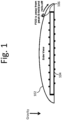
- FIG. 1 An example resonator cover providing a degree of passive FOD protection is shown in Fig. 1 .
- a magnetic resonator 104 of a wireless power transfer system may be surrounded with or enclosed by or placed under a shaped cover 102.
- the cover 102 may be shaped to force FOD 106 to roll down the cover 102 due to the force of gravity.
- the shape of the cover 102 may prevent FOD 106 from accumulating on top of the cover 102 and/or in the vicinity of the resonator 104 by forcing any FOD to the sides of the resonator and/or away from the regions surrounding the resonator where the magnitude of the magnetic fields is high enough to cause a hazardous condition due to heating of the FOD.
- the FOD may be forced far enough away from the high field regions to no longer pose a risk of being heated and/or ignited by the fields.
- a passive FOD technique may include sizing the resonators and/or resonator components to reduce the maximum magnetic field density anywhere in the region of wireless power exchange below a desired limit.
- relatively large resonator coils may be used to mitigate a subset of FOD risks.
- the use of larger resonator coils may be used to reduce the magnetic field strength per unit area required to transfer a certain amount of power wirelessly.
- the maximum magnetic field strength generated by a source may be reduced below a threshold where heating or other hazards may be known to occur.
- Passive mitigation techniques may not always be possible or practical or sufficient.
- reducing a FOD hazard by increasing a resonator size may not be practical owing to the system cost restraints or to the desire to integrate a resonator into a system of a specified volume.
- passive mitigation techniques may be used to at least partially reduce the FOD risk and may be complementary to active mitigation techniques.
- an active mitigation technique for FOD may include a detector system that may detect metallic objects, hot objects, perturbations in resonator parameters, and/or perturbations in magnetic field distributions.
- FOD objects such as metallic objects
- FOD objects may be of sufficient size, extent, and/or material composition to perturb the efficiency or power transfer capabilities of a wireless energy transfer system.
- the presence of said FOD objects may be determined by examining the change in one or more of the voltage, current, and/or power associated with the source resonator and/or device resonator and/or repeater resonator of a wireless power system.
- Some FOD objects may perturb the parameters of the resonators used for energy transfer and/or may perturb the characteristics of the energy transfer.
- a FOD object may change the impedance of a resonator for example.
- these perturbations may be detected by measuring the voltage, current, power, phase, frequency, and the like of the resonators and the wireless energy transfer. Changes or deviations from expected or predicted values may be used to detect the presence of FOD. In an exemplary embodiment, dedicated FOD sensors may not be needed to detect and react to FOD in a wireless power system.
- FOD objects may only weakly perturb the wireless energy transfer and may not be substantially detectable by monitoring electrical parameters of the resonators and/or the characteristics of the wireless energy transfer. Such objects can still create a hazard, however.
- a FOD object that only weakly interacts with the magnetic field may still heat up substantially.
- An example of a FOD object that may only weakly interact with the magnetic field but that may experience significant heating is a metal-foil-and-paper wrapper such as is often found in chewing gum and cigarette packages and as is often used to wrap food from fast food establishments such as Burger King and Kentucky Fried Chicken.
- a chewing gum wrapper When placed between the resonators of a 3.3-kW wireless energy vehicle charging system, a chewing gum wrapper may not be detectable by examining the electrical parameters associated with the resonators and/or the energy transfer system. However, said wrapper may still absorb enough power to rapidly heat and for the paper to eventually burn.
- an active mitigation system for FOD may comprise temperature sensors to detect hot spots, hot areas, and/or hot objects near by the wireless energy transfer system.
- a system may comprise any number of temperature sensors, infrared detectors, cameras, and the like to detect a heat source, heat gradient and the like around the energy transfer system.
- hot object sensing may be used alone or in addition to other active and passive mitigation techniques and can be used to further improve the detectability of heated FOD and/or reduce the false-alarm rate of other active FOD systems.
- an active mitigation system for FOD objects that only weakly perturb the magnetic field between two resonators may comprise sensors for measuring small changes in the magnetic field in the proximity of the FOD objects.
- a metal-foil-and-paper chewing gum wrapper may not substantially alter the magnetic flux between two resonators, but it might substantially alter the magnetic flux through a much smaller sensor coil or loop if it covered and/or blocked any portion of the coil or loop area.
- local disturbances in the magnetic field caused by the presence of FOD may be detected by measuring magnetic field changes, variations, gradients, and the like, in the vicinity of the FOD.
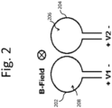
- a FOD sensor may be realized using two small wire loops 202, 204 as shown in Fig. 2 .
- Such a sensor may be placed on or near the resonators used for wireless energy transfer.
- the wireless energy transfer system generates a magnetic field that passes through the two loops.
- Each individual loop develops a voltage proportional to the amount of magnetic flux threading the inside of each loop 206, 208.
- the difference between the voltages developed by the two loops is, to first order, proportional to the gradient of the magnetic field in proximity to the loops. If the two loops are placed in a region of uniform field and the loops are substantially similar, then the difference between the voltages developed by the two loops may be very small.
- the difference in voltage developed by the two loops will be larger than when the wrapper was not present because the metallic foil of the gum wrapper may deflect or/or absorb some of the magnetic flux that would have normally passed through that loop.
- the output from the two loops may be subtracted from each other so that the combination of loops produces a small signal when the sensed field is substantially uniform, and a measurably larger signal when there is a gradient in the field between the two loops.
- the loops and/or coils are configured to generate a signal in the presence of a field gradient, they may be referred to as being arranged as a gradiometer.
- signals from the loops may be subtracted using analog circuitry, digital circuitry and/or by connected the loops together in a specific configuration.
- the sensitivity of the sensor and/or gradiometer may be related to the magnitude and/or phase of the voltage difference between the two loops.
- the sensitivity of the sensor and/or gradiometer may be adjusted to preferentially detect objects of a given size, or above a given size.
- the sensitivity may be adjusted to reduce false detection rates, to lower the noise of the detection system, and/or to operate over a range of frequencies.
- the size and shape of the loops may be adjusted to adjust the sensitivity of the sensor.
- the loops may be adjusted to comprise more turns and or to comprise additional loops, such as four loops, or eight loops for example.
- the loops may be positioned to have rotational symmetry or they may be arranged in a linear arrangement or they may be shaped to fill a region of any size and shape.
- the presence of metallic objects may result in amplitude and/or phase changes in the waveform corresponding to the difference between the two loop voltages.
- the loops may have a plurality of turns.
- the loop areas 206, 208 may be sized according to the magnetic field strength of the wireless energy transfer system, the desired sensitivity of the detection method, the complexity of the system and the like. If the metallic FOD is substantially smaller than the loop area, only a weak signal may arise when the FOD is present. This weak signal may risk being overwhelmed by noise or interfering signals.
- a FOD sensor and/or gradiometer may comprise one or more loops of different sizes, shapes and/or arrangements.
- a FOD sensor may comprise regions with one sensor, more than one sensor or no sensor.
- another way to measure a field gradient in the vicinity of a metallic object may be to create a coil (also referred to as a loop) in a fashion that directly outputs a voltage that is proportional to the local gradient in the magnetic field.
- a coil serves the purpose of the two coils depicted in Fig. 2 , but requires only one voltage measurement. If, for example, one were to double the area of one of the loops depicted in Fig.
- FIG. 3A-3D depicts some exemplary configurations of twisted loops that may be capable of directly outputting a voltage that is proportional to the local gradient in the magnetic field.
- the two loops shown in Fig. 2 may be referred to as magnetic dipoles and the loops in Fig. 3A may be referred to as gradiometers and/or magnetic quadrupoles and the loops in Fig. 3B as gradiometers and/or octupoles, respectively.
- the quadrupole configuration may develop a voltage proportional to the magnetic field gradient in the left-to-right orientation.
- the 4-lobe configurations can be configured to measure field gradients ( Fig. 3B ), and gradients of field gradients ( Fig. 3C).
- Fig. 3D is representative of embodiments where multiple lobes may extend along a linear dimension. In embodiments, higher-order multipoles with an even number of lobes can also be configured to measure spatial perturbations to the magnetic field.
- the lobes depicted in Fig. 3A-3D may use multiple turns of conductor.
- Each of these configurations can accomplish the goal of measuring magnetic field perturbations due to the presence of metallic FOD.
- the configurations with multiple lobes may have an advantage in covering more area without substantially reducing the likelihood of detecting FOD of similar characteristic size to the lobes.
- Fig. 2 and Fig. 3A-3D are depicted as circular to illustrate the direction of the induced current in the presence of an oscillating magnetic field.
- the plus and minus signs indicate whether the induced current flows mostly counter-clock-wise or clock-wise. Shapes other than circles may be better suited for arrays with high-area fill factor. Examples include squares, rectangles, hexagons, and other shapes that tile with little interstitial space in between them.
- Fig. 4A shows an example of square-shaped coils where the array is assumed to extend further than shown and to have an equal number of plus and minus loops. The wires of the coils may be connected so that the induced currents flow in the directions indicated by the plus and minus signs.
- a symmetrical piece of FOD can be placed in a position between adjacent loops so that the field perturbation may not generate a detectable magnetic field gradient.
- a "blind spot" is depicted in Fig. 4A .
- a second layer of arrayed loops may be placed above a first layer and may be offset laterally as shown in Fig. 4B .
- the offset may be chosen so that the "blind spots" of the first layer of sensors correspond to locations of maximum detectability for the second layer.
- the offset may be any offset than improves the likelihood of detection of the FOD relative to the single array detection probability.
- the individual loops or lobes of the dipoles, quadrupoles, octupoles, and the like may be of multiple sizes or of nonuniform sizes.
- the loops may be sized to ensure a minimal voltage at the output of the gradiometer loops when no FOD is present.
- the loops may be sized such that a larger loop is positioned in an area of weaker magnetic field and the smaller loops are positioned in the areas of higher magnetic field.
- the loops may be sized such that a larger loop is positioned in an area of more uniform magnetic field and a smaller loop is positioned in an area of less uniform magnetic field.
- an array of FOD sensors may comprise multiple types of sensors.
- a FOD sensor may comprise single loop sensors and/or dipole gradiometers and/or quadrupole gradiometers and/or octupole gradiometers and so on. Some areas of the FOD sensor may comprise no gradiometers.
- a FOD sensor may comprise temperature sensors, organic material sensors, electric field sensors, magnetic field sensors, capacitive sensors, magnetic sensors, motion sensors, weight sensors, pressure sensors, water sensors, vibration sensors, optical sensors, and any combination of sensors.
- the coil configurations described above may develop an oscillating voltage in the presence of an oscillating magnetic field that is non-uniform because of, for example, the presence of FOD.
- a read-out amplifier connected to a given coil may have a high input impedance. This arrangement may prevent a substantial circulating current from developing in the sensor coil which could, in turn, spoil the Q-factor of the resonators used for wireless energy transfer..
- the loops, coils, gradiometers and the like may be connected to amplifiers and/or filters and/or analog-to-digital converters and/or operational amplifiers, and or any electronic component that may be arranged to have high input impedance.
- a FOD sensor may comprise a conducting loop and a high input impedance electronic component.
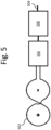
- each conductor pair from each coil (loop, sensor, gradiometer) in an array may be connected to a readout amplifier and/or an analog-to-digital converter as shown in Fig. 5 .
- Each loop conductor 502 may be connected to an amplifier 506 and/or an analog-to-digital converter 508 and may produce an output 504 that may be used by other elements of a wireless energy transfer system or as an input to a processing element (not shown) such as a microprocessor to store and analyze the output of the coil, loop, sensor and/or gradiometer.
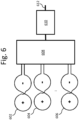
- the voltage on each coil in an array may be measured in sequence or may be multiplexed in a way that allows fewer read-out amplifiers or analog-to-digital converters to sample the array as shown in Fig. 6 .
- An array of loops of gradiometers 602, 604, 606 may be connected to a multiplexed amplifier 608 and connected to one or more digital-to-analog converters 610.
- the output of the digital-to-analog converter 612 may be used by other elements of the wireless energy transfer system or as an input to a processing element (not shown) such as a microprocessor to store and analyze the output of the gradiometer.
- each conductor pair of a sensor and/or gradiometer loop may be connected to active or passive filter circuitry to provide a high terminating impedance at very high or very low frequencies.
- the voltage on a given coil may be sampled at increments that allow a processor to determine the amplitude and phase of the induced waveform relative to a reference waveform.
- the voltage on a given coil may be sampled at least twice per period of oscillation (i.e. at or above the Nyquist rate). In embodiments, the voltage on a given coil may be sampled less frequently (i.e. in higher-order Nyquist bands).
- the voltage waveform may be analog filtered or conditioned before sampling to improve the signal-to-noise ratio or to reduce harmonic content of the signals to be sampled.
- the voltage waveform may be digitally filtered or conditioned after sampling.
- the time-sampled electrical signal from the FOD detector coils may be processed to determine the amplitude and phase with respect to a reference signal.
- the reference signal may be derived from the same clock used to excite the resonators used for wireless energy transfer.
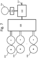
- the FOD detection system may include a separate frequency, field magnitude, and/or phase sampling loop 704 and electronics 702 to synchronize the sensor and/or gradiometer readings to the oscillating magnetic fields of the wireless energy transfer system as shown in Fig. 7 .
- the reference signal may be from a different oscillator at a different frequency.
- FIG. 3A An example of processing a figure-8 quadrupole configuration ( Fig. 3A ) for FOD detection may be as follows:
- the processing of the signal may be performed using analog electronic circuits, digital electronics or both.
- the signals from multiple sensors may be compared and processed.
- FOD sensors may reside on only one, or all, or some of the resonators in a wireless power transfer system.
- the signals from FOD sensors on different resonators may be processed to determine the presence of FOD and/or to give control information to the wireless power system.
- FOD detection may be controllably turned on and off.
- FOD detection and processing may be used to control the frequency of the wireless power transfer system, the power level transferred by the wireless power system, and/or the time period when wireless power transfer is enabled and/or disabled.
- the FOD detectors may be part of a reporting system that may report to a system user that FOD is present and/or that may report to higher level systems that FOD is present or is not present.
- a FOD detection system may comprise a "learning capability" that may be used to identify certain types of FOD and that may comprise system and/or system feedback to categorize types of FOD as harmless, in danger of heating, not allowed for other reasons, and the like.
- processing may be embedded into the FOD detection subsystem or data may be sent back to a central processor.
- the processing may compare collected voltage waveforms to reference waveforms and look for statistically significant changes.
- the waveforms can be compared in amplitude and phase, I or Q components, sine or cosine components, in the complex plane, and the like.
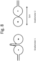
- a stranded wire was formed into a figure-8 loop forming a quadrupole as shown in Fig. 8 with a longer wire between the two loops (gradiometer 1).
- the second embodiment was designed as shown as gradiometer 2 in Fig. 8 .
- the figure-8 loops were approximately 5 cm long.
- Fig. 9A-9C show the voltage waveforms collected from the two sensors placed on top of a wireless energy source between the resonators for a 3.3-kW wireless energy transfer system, when the system was delivering 3.3 kW to a load.
- Fig. 9A shows the small residual voltage ( ⁇ 30 mV rms ) on the two gradiometers pictured Fig. 8 .
- the residual voltage is due to a combination of non-uniform magnetic field, slight variations in lobe area, and electrical interference.
- Results from gradiometers #1 and #2 are plotted in as curve 904 and curve 902, respectively.
- a metallic chewing gum foil is placed on the right lobe of gradiometer #2, some flux is blocked and a substantial amplitude increase and slight phase shift is observable in Fig. 9B , curve 902.
- the foil is moved to the left lobe of gradiometer #2, the amplitude stays the same but the phase changes by 180° as shown in Fig. 9C .
- These changes in phase and amplitude readings may be used to detect the presence of FOD on the sensors.
- An embodiment of the figure-8 sensors was also fabricated using printed-circuit board (PCB) techniques to realize the sensor coils or loops.
- PCB printed-circuit board
- This embodiment may have advantages including low cost, higher fill factor (since the loops can be made into any shape and easily tiled using standard PCB processing techniques), higher uniformity, higher reproducibility, small size and the like.
- a higher-fill factor was obtained using tiled rectangular loops for a 16-channel array of single figure-8 sensors.
- the printed loops were highly uniform resulting in smaller (and flatter) baseline readings from the sensors when no FOD was present.
- the sensors and gradiometer sensors described above can be combined with other types of FOD sensors to improve detection likelihood and lower false alarms (system detects FOD when no FOD is present).
- an array of temperature sensors can be integrated into the resonator assembly. If a piece of FOD begins to heat up it would disturb the normally expected spatial temperature distribution. That deviation can be used to send an alarm to the system controller.
- the temperature sensor may be used alone or in combination with a metal object sensor and/or it may be used as a backup or confirming sensor to the metallic object sensor.
- Living beings such as pets can be difficult to detect. In general, they may not interact in a substantial manner with the magnetic field. In addition, living beings may not heat up appreciably when exposed to magnetic fields. Nonetheless, a wireless power system may need to shut down if living beings intrude into magnetic fields of certain field strengths.
- the field strength limits may be frequency dependent and may be based on regulatory limits, safety limits, standards limits, public perception limits, and the like.
- a dielectric sensor that measures changes in the fringe capacitance from a conductor such as a long wire can detect the proximity of living beings. In embodiments, this type of sensor may be used during diagnostic testing, prior to wireless energy transfer, and during wireless energy transfer.
- Detection of FOD may be an important safety precaution in many types of wireless energy transfer systems.
- a 3.3-kW car charging system an example of an embodiment follows.
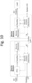
- FIG. 10 A block diagram of an exemplary EV Charger System is shown in Fig. 10 .
- the system may be partitioned into a Source Module and a Device Module.
- the Source Module may be part of a charging station and the Device module may be mounted onto an electric vehicle.
- Power is wirelessly transferred from the Source to the Device via the resonators. Closed loop control of the transmitted power may be performed through an in-band and/or out-of-band RF communications link between the Source and Device Modules.
- a FOD detector system (not shown) can be integrated into the system in a variety of places.
- FOD systems may be integrated into the Source Module, into the source resonator, into the housings or enclosures of the source resonator and the like.
- the FOD systems may be integrated on the device side of the system.
- FOD systems may be implemented on both the source and device sides of the wireless power transmission system.
- the FOD detection system may include multiple sensors and a processor with a discrimination algorithm. The processor can be connected to an interface that functions as an interlock in the Source control electronics.
- Other FOD detector systems may be connected to the charger systems through an additional interface or through an external interface. Local I/O at each module may provide interface for system level management and control functions in a wireless power system utilizing FOD detection.
- the source resonator in a high power (3.3+ kW) vehicle charging system may have its highest magnetic field density near the boundaries of the windings and, optionally, any magnetic material.
- an array comprising multiple channels of double- figure 8 coils with rectangular-shaped lobes can protect against inadvertent heating of metallic FOD.
- the array may be fabricated on a PCB and may have integrated filtering and signal conditioning included on the board.
- a second PCB of equivalent design may be positioned slightly above the first PCB and translated laterally in the manner described in Fig. 4B .
- An algorithm like that described above may run in an on-board processor whose output may be transmitted to a system controller.
- the system controller can compare the output of the metallic FOD detector to the outputs of additional FOD detectors such as those measuring temperature profiles or dielectric changes. The system can then decide whether to turn down or shut down the system if FOD is detected.
Landscapes
- Engineering & Computer Science (AREA)
- Power Engineering (AREA)
- Physics & Mathematics (AREA)
- Computer Networks & Wireless Communication (AREA)
- General Physics & Mathematics (AREA)
- Life Sciences & Earth Sciences (AREA)
- Remote Sensing (AREA)
- Transportation (AREA)
- Mechanical Engineering (AREA)
- Condensed Matter Physics & Semiconductors (AREA)
- Electromagnetism (AREA)
- Environmental & Geological Engineering (AREA)
- Geology (AREA)
- General Life Sciences & Earth Sciences (AREA)
- Geophysics (AREA)
- Measuring Magnetic Variables (AREA)
- Geophysics And Detection Of Objects (AREA)
- Arrangements For Transmission Of Measured Signals (AREA)
Claims (12)
- Drahtloses Ladesystem mit Fremdkörpererkennung, wobei das System Folgendes umfasst:mindestens eine drahtlose Energieübertragungsquelle mit einem Quellenresonator, der so konfiguriert ist, dass er ein oszillierendes Magnetfeld erzeugt; undein Fremdkörper-Erkennungssystem, das Folgendes umfasst:mindestens einen Magnetfeldsensor (202, 204, 502, 602, 604, 606), undmindestens eine Ausleseschaltung (506, 508, 608, 610, 704, 702) zur Messung elektrischer Parameter des mindestens einen Magnetfeldsensors, dadurch gekennzeichnet, dass:der mindestens eine Magnetfeldsensor innerhalb des oszillierenden Magnetfelds positioniert ist, das durch den Quellenresonator des drahtlosen Ladesystems erzeugt wird, und konfiguriert ist, um Magnetfeldstörungen des oszillierenden Magnetfelds zu messen, das durch den Quellenresonator der drahtlosen Energieübertragungsquelle erzeugt wird;wobei die Magnetfeldstörungen das Vorhandensein von metallischen Fremdkörpern anzeigen, undwobei das Fremdkörper-Erkennungssystem so konfiguriert ist, dass es verifiziert, dass sich während des Ladens durch die drahtlose Energieübertragungsquelle keine metallischen Fremdkörper auf den Quellenresonator bewegt haben.
- Drahtloses Ladesystem nach Anspruch 1,
wobei das drahtlose Ladesystem ein drahtloses Fahrzeugladesystem ist. - Drahtloses Ladesystem nach Anspruch 2,
wobei das Fremdkörper-Erkennungssystem ferner so konfiguriert ist, dass es auf Fremdkörper prüft, bevor ein Fahrzeug die mindestens eine drahtlose Energieübertragungsquelle überfährt. - Drahtloses Ladesystem nach Anspruch 3,
wobei das Fremdkörper-Erkennungssystem ferner so konfiguriert ist, dass es überprüft, ob die mindestens eine drahtlose Energieübertragungsquelle noch frei von Fremdkörpern ist, nachdem ein Fahrzeug angekommen ist und über der mindestens einen drahtlosen Energieübertragungsquelle positioniert wurde, jedoch vor dem Aufladen. - Drahtloses Ladesystem nach einem der Ansprüche 1 bis 4,
wobei die mindestens eine drahtlose Energieübertragungsquelle Teil einer Ladestation ist. - Drahtloses Ladesystem nach Anspruch 5,
wobei das drahtlose Ladesystem ferner ein Gerätemodul umfasst, das so konfiguriert ist, dass es Strom von der mindestens einen drahtlosen Energieübertragungsquelle empfängt und so konfiguriert ist, dass es an einem Elektrofahrzeug angebracht werden kann. - Drahtloses Ladesystem nach einem der vorhergehenden Ansprüche,
wobei das Fremdkörper-Erkennungssystem in die mindestens eine drahtlose Energieübertragungsquelle, in den Quellenresonator oder in ein Gehäuse oder eine Einfassung des Quellenresonators integriert ist. - Drahtloses Ladesystem nach einem der vorhergehenden
wobei das drahtlose Ladesystem so konfiguriert ist, dass es eine Leistung von mehr als 3,3 kW liefert. - Drahtloses Ladesystem nach einem der vorhergehenden Ansprüche,wobei der mindestens eine Magnetfeldsensor (202, 204, 502, 602, 604, 606) mehrere Schleifen umfasst, die so bemessen sind, dass eine größere Schleife in einem Bereich mit schwächerem Magnetfeld und kleinere Schleifen in Bereichen mit stärkerem Magnetfeld angeordnet sind, oderwobei die mehreren Schleifen so bemessen sind, dass eine größere Schleife in einem Bereich mit einem gleichmäßigeren Magnetfeld und eine kleinere Schleife in einem Bereich mit einem weniger gleichmäßigen Magnetfeld angeordnet ist.
- Verfahren zur Erkennung von Fremdkörpern in einem drahtlosen Ladesystem, wobei das System Folgendes umfasst:- mindestens eine drahtlose Energieübertragungsquelle mit einem Quellenresonator, der so konfiguriert ist, dass er ein oszillierendes Magnetfeld erzeugt; und- ein Fremdkörper-Erkennungssystem, das Folgendes umfasst:- mindestens einen Magnetfeldsensor (202, 204, 502, 602, 604, 606), und- mindestens eine Ausleseschaltung (506, 508, 608, 610, 704, 702) zur Messung elektrischer Parameter des mindestens einen Magnetfeldsensors, und dadurch gekennzeichnet, dass:der mindestens eine Magnetfeldsensor innerhalb des oszillierenden Magnetfelds positioniert ist, das durch den Quellenresonator des drahtlosen Ladesystems erzeugt wird, und konfiguriert ist, um Magnetfeldstörungen des oszillierenden Magnetfelds zu messen, das durch den Quellenresonator der drahtlosen Energieübertragungsquelle erzeugt wird;wobei die Magnetfeldstörungen das Vorhandensein von metallischen Fremdkörpern anzeigen, wobei das Verfahren Folgendes umfasst:
während des Aufladens eines Fahrzeugs, Überprüfen, dass keine metallischen Fremdkörper auf eine Spule eines Quellenresonators des drahtlosen Ladesystems gelangt sind. - Verfahren zum Erkennen von Fremdkörpern in einem drahtlosen Ladesystem nach Anspruch 10, ferner Folgendes umfassend:
nach der Ankunft eines Fahrzeugs, das sich über dem Quellenresonator befindet, aber vor dem Aufladen mit hoher Leistung, Überprüfen, ob die Quelle noch frei von Fremdkörpern ist. - Verfahren zum Erkennen von Fremdkörpern in einem drahtlosen Ladesystem nach Anspruch 11, ferner Folgendes umfassend:
Durchführen von Tests ohne die Anwesenheit des Fahrzeugs, um den Zustand einer Ladestation einschließlich des Quellenresonators zu überprüfen, und um vor dem Überfahren des Quellenresonators durch ein Fahrzeug zu prüfen, ob Fremdkörper vorhanden sind.
Applications Claiming Priority (3)
| Application Number | Priority Date | Filing Date | Title |
|---|---|---|---|
| US201161532785P | 2011-09-09 | 2011-09-09 | |
| PCT/US2012/054490 WO2013036947A2 (en) | 2011-09-09 | 2012-09-10 | Foreign object detection in wireless energy transfer systems |
| EP12830255.1A EP2754222B1 (de) | 2011-09-09 | 2012-09-10 | Fremdkörpererkennung in drahtlosen energieübertragungssystemen |
Related Parent Applications (1)
| Application Number | Title | Priority Date | Filing Date |
|---|---|---|---|
| EP12830255.1A Division EP2754222B1 (de) | 2011-09-09 | 2012-09-10 | Fremdkörpererkennung in drahtlosen energieübertragungssystemen |
Publications (2)
| Publication Number | Publication Date |
|---|---|
| EP2998153A1 EP2998153A1 (de) | 2016-03-23 |
| EP2998153B1 true EP2998153B1 (de) | 2023-11-01 |
Family
ID=47832816
Family Applications (2)
| Application Number | Title | Priority Date | Filing Date |
|---|---|---|---|
| EP15190252.5A Active EP2998153B1 (de) | 2011-09-09 | 2012-09-10 | Fremdkörpererkennung in drahtlosen energieübertragungssystemen |
| EP12830255.1A Active EP2754222B1 (de) | 2011-09-09 | 2012-09-10 | Fremdkörpererkennung in drahtlosen energieübertragungssystemen |
Family Applications After (1)
| Application Number | Title | Priority Date | Filing Date |
|---|---|---|---|
| EP12830255.1A Active EP2754222B1 (de) | 2011-09-09 | 2012-09-10 | Fremdkörpererkennung in drahtlosen energieübertragungssystemen |
Country Status (9)
| Country | Link |
|---|---|
| US (3) | US9442172B2 (de) |
| EP (2) | EP2998153B1 (de) |
| JP (1) | JP6185472B2 (de) |
| KR (2) | KR102010943B1 (de) |
| CN (1) | CN103875159B (de) |
| AU (1) | AU2012305688B2 (de) |
| CA (1) | CA2848040C (de) |
| ES (1) | ES2558182T3 (de) |
| WO (1) | WO2013036947A2 (de) |
Families Citing this family (218)
| Publication number | Priority date | Publication date | Assignee | Title |
|---|---|---|---|---|
| US8805530B2 (en) | 2007-06-01 | 2014-08-12 | Witricity Corporation | Power generation for implantable devices |
| US9421388B2 (en) | 2007-06-01 | 2016-08-23 | Witricity Corporation | Power generation for implantable devices |
| US8947186B2 (en) * | 2008-09-27 | 2015-02-03 | Witricity Corporation | Wireless energy transfer resonator thermal management |
| US9601266B2 (en) | 2008-09-27 | 2017-03-21 | Witricity Corporation | Multiple connected resonators with a single electronic circuit |
| US8692412B2 (en) * | 2008-09-27 | 2014-04-08 | Witricity Corporation | Temperature compensation in a wireless transfer system |
| US8482158B2 (en) | 2008-09-27 | 2013-07-09 | Witricity Corporation | Wireless energy transfer using variable size resonators and system monitoring |
| US9396867B2 (en) | 2008-09-27 | 2016-07-19 | Witricity Corporation | Integrated resonator-shield structures |
| US8669676B2 (en) | 2008-09-27 | 2014-03-11 | Witricity Corporation | Wireless energy transfer across variable distances using field shaping with magnetic materials to improve the coupling factor |
| US9105959B2 (en) | 2008-09-27 | 2015-08-11 | Witricity Corporation | Resonator enclosure |
| US9601270B2 (en) | 2008-09-27 | 2017-03-21 | Witricity Corporation | Low AC resistance conductor designs |
| US8901778B2 (en) | 2008-09-27 | 2014-12-02 | Witricity Corporation | Wireless energy transfer with variable size resonators for implanted medical devices |
| US20100259110A1 (en) * | 2008-09-27 | 2010-10-14 | Kurs Andre B | Resonator optimizations for wireless energy transfer |
| US8957549B2 (en) | 2008-09-27 | 2015-02-17 | Witricity Corporation | Tunable wireless energy transfer for in-vehicle applications |
| US8643326B2 (en) | 2008-09-27 | 2014-02-04 | Witricity Corporation | Tunable wireless energy transfer systems |
| US8629578B2 (en) | 2008-09-27 | 2014-01-14 | Witricity Corporation | Wireless energy transfer systems |
| US8946938B2 (en) | 2008-09-27 | 2015-02-03 | Witricity Corporation | Safety systems for wireless energy transfer in vehicle applications |
| US8937408B2 (en) | 2008-09-27 | 2015-01-20 | Witricity Corporation | Wireless energy transfer for medical applications |
| US9577436B2 (en) | 2008-09-27 | 2017-02-21 | Witricity Corporation | Wireless energy transfer for implantable devices |
| US9601261B2 (en) | 2008-09-27 | 2017-03-21 | Witricity Corporation | Wireless energy transfer using repeater resonators |
| US8598743B2 (en) | 2008-09-27 | 2013-12-03 | Witricity Corporation | Resonator arrays for wireless energy transfer |
| US8922066B2 (en) | 2008-09-27 | 2014-12-30 | Witricity Corporation | Wireless energy transfer with multi resonator arrays for vehicle applications |
| US8901779B2 (en) | 2008-09-27 | 2014-12-02 | Witricity Corporation | Wireless energy transfer with resonator arrays for medical applications |
| US8410636B2 (en) | 2008-09-27 | 2013-04-02 | Witricity Corporation | Low AC resistance conductor designs |
| US9184595B2 (en) | 2008-09-27 | 2015-11-10 | Witricity Corporation | Wireless energy transfer in lossy environments |
| US20100277121A1 (en) * | 2008-09-27 | 2010-11-04 | Hall Katherine L | Wireless energy transfer between a source and a vehicle |
| US8772973B2 (en) | 2008-09-27 | 2014-07-08 | Witricity Corporation | Integrated resonator-shield structures |
| US8497601B2 (en) | 2008-09-27 | 2013-07-30 | Witricity Corporation | Wireless energy transfer converters |
| US8963488B2 (en) | 2008-09-27 | 2015-02-24 | Witricity Corporation | Position insensitive wireless charging |
| US8912687B2 (en) | 2008-09-27 | 2014-12-16 | Witricity Corporation | Secure wireless energy transfer for vehicle applications |
| US8928276B2 (en) | 2008-09-27 | 2015-01-06 | Witricity Corporation | Integrated repeaters for cell phone applications |
| US9246336B2 (en) | 2008-09-27 | 2016-01-26 | Witricity Corporation | Resonator optimizations for wireless energy transfer |
| US8907531B2 (en) | 2008-09-27 | 2014-12-09 | Witricity Corporation | Wireless energy transfer with variable size resonators for medical applications |
| US9065423B2 (en) | 2008-09-27 | 2015-06-23 | Witricity Corporation | Wireless energy distribution system |
| US8933594B2 (en) | 2008-09-27 | 2015-01-13 | Witricity Corporation | Wireless energy transfer for vehicles |
| US8723366B2 (en) * | 2008-09-27 | 2014-05-13 | Witricity Corporation | Wireless energy transfer resonator enclosures |
| US9318922B2 (en) | 2008-09-27 | 2016-04-19 | Witricity Corporation | Mechanically removable wireless power vehicle seat assembly |
| US9035499B2 (en) | 2008-09-27 | 2015-05-19 | Witricity Corporation | Wireless energy transfer for photovoltaic panels |
| US9106203B2 (en) | 2008-09-27 | 2015-08-11 | Witricity Corporation | Secure wireless energy transfer in medical applications |
| US9093853B2 (en) | 2008-09-27 | 2015-07-28 | Witricity Corporation | Flexible resonator attachment |
| US9515494B2 (en) | 2008-09-27 | 2016-12-06 | Witricity Corporation | Wireless power system including impedance matching network |
| US8400017B2 (en) | 2008-09-27 | 2013-03-19 | Witricity Corporation | Wireless energy transfer for computer peripheral applications |
| US9544683B2 (en) | 2008-09-27 | 2017-01-10 | Witricity Corporation | Wirelessly powered audio devices |
| US9160203B2 (en) | 2008-09-27 | 2015-10-13 | Witricity Corporation | Wireless powered television |
| US9744858B2 (en) | 2008-09-27 | 2017-08-29 | Witricity Corporation | System for wireless energy distribution in a vehicle |
| US20110302078A1 (en) | 2010-06-02 | 2011-12-08 | Bryan Marc Failing | Managing an energy transfer between a vehicle and an energy transfer system |
| US9602168B2 (en) | 2010-08-31 | 2017-03-21 | Witricity Corporation | Communication in wireless energy transfer systems |
| US9948145B2 (en) | 2011-07-08 | 2018-04-17 | Witricity Corporation | Wireless power transfer for a seat-vest-helmet system |
| WO2013020138A2 (en) | 2011-08-04 | 2013-02-07 | Witricity Corporation | Tunable wireless power architectures |
| US9442172B2 (en) | 2011-09-09 | 2016-09-13 | Witricity Corporation | Foreign object detection in wireless energy transfer systems |
| US20130062966A1 (en) | 2011-09-12 | 2013-03-14 | Witricity Corporation | Reconfigurable control architectures and algorithms for electric vehicle wireless energy transfer systems |
| US9318257B2 (en) | 2011-10-18 | 2016-04-19 | Witricity Corporation | Wireless energy transfer for packaging |
| KR20140085591A (ko) | 2011-11-04 | 2014-07-07 | 위트리시티 코포레이션 | 무선 에너지 전송 모델링 툴 |
| US9079043B2 (en) | 2011-11-21 | 2015-07-14 | Thoratec Corporation | Transcutaneous power transmission utilizing non-planar resonators |
| JP5838768B2 (ja) | 2011-11-30 | 2016-01-06 | ソニー株式会社 | 検知装置、受電装置、非接触電力伝送システム及び検知方法 |
| JP2015508987A (ja) | 2012-01-26 | 2015-03-23 | ワイトリシティ コーポレーションWitricity Corporation | 減少した場を有する無線エネルギー伝送 |
| CN107370249B (zh) | 2012-03-14 | 2020-06-09 | 索尼公司 | 电力发送装置以及非接触电力提供系统 |
| JP5967989B2 (ja) | 2012-03-14 | 2016-08-10 | ソニー株式会社 | 検知装置、受電装置、送電装置及び非接触給電システム |
| JP2013192391A (ja) * | 2012-03-14 | 2013-09-26 | Sony Corp | 検知装置、受電装置、送電装置及び非接触給電システム |
| WO2013142866A1 (en) | 2012-03-23 | 2013-09-26 | Hevo Inc. | Systems and mobile application for electric wireless charging stations |
| DE102012205285A1 (de) * | 2012-03-30 | 2013-10-02 | Bayerische Motoren Werke Aktiengesellschaft | Vorrichtung zur induktiven Leistungsübertragung |
| CN104823353B (zh) | 2012-05-02 | 2018-03-20 | 鲍尔拜普罗克西有限公司 | 用于在感应功率传输系统中检测和识别接收器的方法 |
| US9343922B2 (en) | 2012-06-27 | 2016-05-17 | Witricity Corporation | Wireless energy transfer for rechargeable batteries |
| US9287607B2 (en) | 2012-07-31 | 2016-03-15 | Witricity Corporation | Resonator fine tuning |
| US9595378B2 (en) | 2012-09-19 | 2017-03-14 | Witricity Corporation | Resonator enclosure |
| US9465064B2 (en) | 2012-10-19 | 2016-10-11 | Witricity Corporation | Foreign object detection in wireless energy transfer systems |
| EP2915233A1 (de) | 2012-11-05 | 2015-09-09 | Powerbyproxi Limited | Induktiv gekoppelte stromübertragungssysteme |
| US9449757B2 (en) | 2012-11-16 | 2016-09-20 | Witricity Corporation | Systems and methods for wireless power system with improved performance and/or ease of use |
| GB2508923A (en) | 2012-12-17 | 2014-06-18 | Bombardier Transp Gmbh | Inductive power transfer system having inductive sensing array |
| US9365126B2 (en) | 2013-05-10 | 2016-06-14 | Qualcomm Incorporated | System and method for detecting the presence of a moving object below a vehicle |
| JP2014225962A (ja) * | 2013-05-16 | 2014-12-04 | ソニー株式会社 | 検知装置、給電システム、および、検知装置の制御方法 |
| JP2014225963A (ja) * | 2013-05-16 | 2014-12-04 | ソニー株式会社 | 検知装置、給電システム、および、検知装置の制御方法 |
| JP2014225961A (ja) * | 2013-05-16 | 2014-12-04 | ソニー株式会社 | 検知装置、給電システム、および、検知装置の制御方法 |
| GB2517679A (en) | 2013-06-25 | 2015-03-04 | Bombardier Transp Gmbh | Object detection system and method for operating an object detection system |
| EP3025411B1 (de) | 2013-07-12 | 2018-09-26 | Schneider Electric USA, Inc. | Verfahren und vorrichtung zur fremdobjekterkennung bei einer elektrischen induktionsladevorrichtung |
| EP3039770B1 (de) | 2013-08-14 | 2020-01-22 | WiTricity Corporation | Impedanzabstimmung |
| JP6478450B2 (ja) * | 2013-09-13 | 2019-03-06 | 株式会社テクノバ | 金物異物の検知可能な非接触給電装置とその金物異物検知方法 |
| DE102013219131B4 (de) * | 2013-09-24 | 2018-07-19 | Siemens Aktiengesellschaft | Vorrichtung und Verfahren zur Erkennung eines Fremdkörpers in einem zur leitungslosen Energieübertragung vorgesehenen Magnetfeld |
| JP6171853B2 (ja) | 2013-10-30 | 2017-08-02 | 株式会社デンソー | 非接触給電制御システム |
| DE102013223794A1 (de) * | 2013-11-21 | 2015-05-21 | Robert Bosch Gmbh | Energieübertragungssystem und Verfahren zur Diagnose eines Energieübertragungssystems |
| US9153998B2 (en) * | 2013-12-02 | 2015-10-06 | Qualcomm Incorporated | Wireless power orthogonal polarization antenna array |
| GB2520990A (en) * | 2013-12-06 | 2015-06-10 | Bombardier Transp Gmbh | Inductive power transfer for transferring electric energy to a vehicle |
| US9941751B2 (en) | 2014-01-27 | 2018-04-10 | Mediatek Inc. | Method for performing wireless charging control of an electronic device with aid of predetermined data in non-volatile memory, and associated apparatus |
| US9780573B2 (en) | 2014-02-03 | 2017-10-03 | Witricity Corporation | Wirelessly charged battery system |
| WO2015123614A2 (en) | 2014-02-14 | 2015-08-20 | Witricity Corporation | Object detection for wireless energy transfer systems |
| EP3108570B1 (de) * | 2014-02-19 | 2020-09-09 | Samsung Electronics Co., Ltd | Verfahren zur detektion von ladung beim drahtlosen laden |
| US9716861B1 (en) | 2014-03-07 | 2017-07-25 | Steelcase Inc. | Method and system for facilitating collaboration sessions |
| US10664772B1 (en) | 2014-03-07 | 2020-05-26 | Steelcase Inc. | Method and system for facilitating collaboration sessions |
| CN103944214A (zh) * | 2014-03-17 | 2014-07-23 | 广东工业大学 | 一种无线充电装置 |
| DE102014205598A1 (de) * | 2014-03-26 | 2015-10-01 | Robert Bosch Gmbh | Überwachungsvorrichtung für mindestens eine zur induktiven Energieübertragung ausgelegte elektrische Vorrichtung und Verfahren zum Überwachen zumindest einer Teilumgebung mindestens einer zur induktiven Energieübertragung ausgelegten elektrischen Vorrichtung |
| US9793720B2 (en) * | 2014-04-16 | 2017-10-17 | The Regents Of The University Of Michigan | Wireless power transfer using multiple near-field plates |
| US10114120B2 (en) | 2014-04-16 | 2018-10-30 | The Regents Of The University Of Michigan | Unidirectional near-field focusing using near-field plates |
| CN106464030B (zh) | 2014-04-16 | 2019-09-13 | 无线电力公司 | 用于移动设备应用的无线能量传输 |
| GB2525239A (en) | 2014-04-17 | 2015-10-21 | Bombardier Transp Gmbh | Object detection system and method for detecting foreign objects in an inductive power transfer system |
| DE102014207427A1 (de) | 2014-04-17 | 2015-10-22 | Bombardier Transportation Gmbh | Vorrichtung und Verfahren zur Detektion eines Störkörpers in einem System zur induktiven Energieübertragung sowie System zur induktiven Energieübertragung |
| US9842687B2 (en) | 2014-04-17 | 2017-12-12 | Witricity Corporation | Wireless power transfer systems with shaped magnetic components |
| US9892849B2 (en) | 2014-04-17 | 2018-02-13 | Witricity Corporation | Wireless power transfer systems with shield openings |
| JP6248785B2 (ja) * | 2014-04-25 | 2017-12-20 | トヨタ自動車株式会社 | 送電装置および受電装置 |
| US9837860B2 (en) | 2014-05-05 | 2017-12-05 | Witricity Corporation | Wireless power transmission systems for elevators |
| CN106489082B (zh) * | 2014-05-07 | 2021-09-21 | 无线电力公司 | 无线能量传送系统中的异物检测 |
| GB2526307A (en) * | 2014-05-20 | 2015-11-25 | Bombardier Transp Gmbh | A housing for at least one object detection device, a primary unit and a pavement slab assembly |
| US9766079B1 (en) | 2014-10-03 | 2017-09-19 | Steelcase Inc. | Method and system for locating resources and communicating within an enterprise |
| US9380682B2 (en) | 2014-06-05 | 2016-06-28 | Steelcase Inc. | Environment optimization for space based on presence and activities |
| US9955318B1 (en) | 2014-06-05 | 2018-04-24 | Steelcase Inc. | Space guidance and management system and method |
| US10614694B1 (en) | 2014-06-06 | 2020-04-07 | Steelcase Inc. | Powered furniture assembly |
| US10433646B1 (en) | 2014-06-06 | 2019-10-08 | Steelcaase Inc. | Microclimate control systems and methods |
| US11744376B2 (en) | 2014-06-06 | 2023-09-05 | Steelcase Inc. | Microclimate control systems and methods |
| WO2015196123A2 (en) * | 2014-06-20 | 2015-12-23 | Witricity Corporation | Wireless power transfer systems for surfaces |
| JP6166227B2 (ja) * | 2014-07-04 | 2017-07-19 | トヨタ自動車株式会社 | 送電装置及び受電装置 |
| US10574091B2 (en) | 2014-07-08 | 2020-02-25 | Witricity Corporation | Enclosures for high power wireless power transfer systems |
| JP6518316B2 (ja) | 2014-07-08 | 2019-05-22 | ワイトリシティ コーポレーションWitricity Corporation | 無線電力伝送システムにおける共振器の均衡化 |
| US9852388B1 (en) | 2014-10-03 | 2017-12-26 | Steelcase, Inc. | Method and system for locating resources and communicating within an enterprise |
| KR20170072357A (ko) * | 2014-11-11 | 2017-06-26 | 파워바이프록시 리미티드 | 유도식 전력 송신기 |
| US9804034B2 (en) | 2014-11-14 | 2017-10-31 | Schneider Electric USA, Inc. | EVSE with cordset handle temperature measurement |
| US9707850B2 (en) | 2014-11-18 | 2017-07-18 | Schneider Electric USA, Inc. | EVSE handle with automatic thermal shut down by NTC to ground |
| WO2016088261A1 (ja) * | 2014-12-05 | 2016-06-09 | 三菱電機エンジニアリング株式会社 | 共振型電力伝送システム、送信装置及び給電位置制御システム |
| CN104682488A (zh) * | 2014-12-26 | 2015-06-03 | 中兴新能源汽车有限责任公司 | 异物检测装置、方法及无线充电系统 |
| US9843217B2 (en) | 2015-01-05 | 2017-12-12 | Witricity Corporation | Wireless energy transfer for wearables |
| CN107112799B (zh) | 2015-01-19 | 2020-04-07 | 株式会社Ihi | 输电系统、异物检测装置以及线圈装置 |
| US20160241061A1 (en) | 2015-02-17 | 2016-08-18 | Qualcomm Incorporated | Clover leaf and butterfly coil structures for flat wireless coupling profiles in wireless power transfer applications |
| JP6732779B2 (ja) | 2015-03-04 | 2020-07-29 | アップル インコーポレイテッドApple Inc. | 誘導電力送信器 |
| US9829599B2 (en) * | 2015-03-23 | 2017-11-28 | Schneider Electric USA, Inc. | Sensor and method for foreign object detection in induction electric charger |
| CN107529346B (zh) | 2015-04-02 | 2021-03-02 | 苹果公司 | 感应电力发射器 |
| USD773411S1 (en) | 2015-04-27 | 2016-12-06 | Witricity Corporation | Resonator coil |
| USD770402S1 (en) | 2015-05-15 | 2016-11-01 | Witricity Corporation | Coil |
| USD769835S1 (en) | 2015-05-15 | 2016-10-25 | Witricity Corporation | Resonator coil |
| USD770403S1 (en) | 2015-05-15 | 2016-11-01 | Witricity Corporation | Coil |
| US10733371B1 (en) | 2015-06-02 | 2020-08-04 | Steelcase Inc. | Template based content preparation system for use with a plurality of space types |
| JP6650219B2 (ja) * | 2015-06-25 | 2020-02-19 | ローム株式会社 | 送電装置及び非接触給電システム |
| USD770404S1 (en) | 2015-08-05 | 2016-11-01 | Witricity Corporation | Resonator coil |
| US10675980B2 (en) | 2015-09-04 | 2020-06-09 | Intel Corporation | Wireless charging apparatus with controlled power level adjustment |
| US10033230B2 (en) * | 2015-09-25 | 2018-07-24 | Intel Corporation | Controlling a wireless power transmitter based on human presence |
| DE102015218437A1 (de) | 2015-09-25 | 2017-03-30 | Bayerische Motoren Werke Aktiengesellschaft | Verfahren zur Herstellung einer Induktionsspule |
| WO2017062647A1 (en) | 2015-10-06 | 2017-04-13 | Witricity Corporation | Rfid tag and transponder detection in wireless energy transfer systems |
| EP3362804B1 (de) | 2015-10-14 | 2024-01-17 | WiTricity Corporation | Phasen- und amplitudendetektion in systemen zur drahtlosen energieübertragung |
| US10063110B2 (en) | 2015-10-19 | 2018-08-28 | Witricity Corporation | Foreign object detection in wireless energy transfer systems |
| WO2017070009A1 (en) | 2015-10-22 | 2017-04-27 | Witricity Corporation | Dynamic tuning in wireless energy transfer systems |
| JP6600413B2 (ja) | 2015-11-19 | 2019-10-30 | アップル インコーポレイテッド | 誘導電力送信機 |
| US10075019B2 (en) | 2015-11-20 | 2018-09-11 | Witricity Corporation | Voltage source isolation in wireless power transfer systems |
| JP6069548B1 (ja) * | 2016-01-22 | 2017-02-01 | 日本電信電話株式会社 | ループアンテナアレイ群 |
| EP3203604B1 (de) | 2016-02-02 | 2018-11-14 | WiTricity Corporation | Steuerung von system zur drahtlosen stromübertragung |
| JP6888017B2 (ja) | 2016-02-08 | 2021-06-16 | ワイトリシティ コーポレーションWitricity Corporation | Pwmコンデンサの制御 |
| USD814432S1 (en) | 2016-02-09 | 2018-04-03 | Witricity Corporation | Resonator coil |
| AU2017248083B2 (en) | 2016-04-04 | 2020-05-21 | Apple Inc | Inductive power transmitter |
| US11424645B2 (en) * | 2016-05-10 | 2022-08-23 | Koninklijke Philips N.V. | Foreign object detection in a wireless power transfer system |
| GB201609254D0 (en) * | 2016-05-25 | 2016-07-06 | Isis Innovation | Wireless power transfer system |
| US9921726B1 (en) | 2016-06-03 | 2018-03-20 | Steelcase Inc. | Smart workstation method and system |
| US11086042B2 (en) | 2016-06-13 | 2021-08-10 | Lg Innotek Co., Ltd. | Method for detecting foreign material, and apparatus and system therefor |
| US10128698B2 (en) | 2016-06-20 | 2018-11-13 | Hyundai America Technical Center, Inc | Device and method for detecting an object within a wireless charging region |
| US20180056800A1 (en) | 2016-07-28 | 2018-03-01 | Witricity Corporation | Relative position determination and vehicle guidance in wireless power transfer systems |
| US10181759B2 (en) * | 2016-09-14 | 2019-01-15 | Qualcomm Incorporated | Dynamic mutual sensing foreign object detection loops |
| US10124687B2 (en) | 2016-09-14 | 2018-11-13 | Qualcomm Incorporated | Hybrid foreign object detection (FOD) loop array board |
| DE102016217704A1 (de) | 2016-09-15 | 2018-03-15 | Bayerische Motoren Werke Aktiengesellschaft | Verfahren zur Überwachung eines induktiven Ladevorgangs |
| WO2018064357A1 (en) * | 2016-09-28 | 2018-04-05 | Witricity Corporation | Mitigating false detection of foreign objects in wireless power systems |
| DE102016219484A1 (de) * | 2016-10-07 | 2018-04-12 | Bayerische Motoren Werke Aktiengesellschaft | Maschenwerk und Vorrichtung zur Objekterkennung in einem Magnetfeld, Verfahren zur Herstellung des Maschenwerks und induktive Ladeeinheit |
| US10369894B2 (en) | 2016-10-21 | 2019-08-06 | Hevo, Inc. | Parking alignment sequence for wirelessly charging an electric vehicle |
| US10264213B1 (en) | 2016-12-15 | 2019-04-16 | Steelcase Inc. | Content amplification system and method |
| US10476313B2 (en) | 2017-01-26 | 2019-11-12 | Denso Corporation | Foreign object detection in a wireless power transfer system |
| US11271429B2 (en) | 2017-03-07 | 2022-03-08 | Powermat Technologies Ltd. | System for wireless power charging |
| CN110785912B (zh) | 2017-03-07 | 2024-05-14 | 鲍尔马特技术有限公司 | 用于无线电力充电的系统 |
| KR102673854B1 (ko) | 2017-03-07 | 2024-06-10 | 파워매트 테크놀로지스 엘티디. | 무선 전력 충전 시스템 |
| CN110771004A (zh) | 2017-03-07 | 2020-02-07 | 鲍尔马特技术有限公司 | 用于无线电力充电的系统 |
| DE102017206377A1 (de) * | 2017-04-13 | 2018-10-18 | Continental Automotive Gmbh | Überwachungseinrichtung zum Überwachen einer berührungslosen Ladeeinrichtung zum berührungslosen elektrischen Laden eines Kraftfahrzeugs, berührungslose Ladeeinrichtung, Kraftfahrzeug und Verfahren zum Betreiben einer Überwachungseinrichtung |
| US10128697B1 (en) | 2017-05-01 | 2018-11-13 | Hevo, Inc. | Detecting and deterring foreign objects and living objects at wireless charging stations |
| US10566848B2 (en) * | 2017-05-02 | 2020-02-18 | Chargedge, Inc. | Foreign object detection in wireless power transfer by asymmetry detection |
| US11101704B2 (en) | 2017-05-23 | 2021-08-24 | Tdk Electronics Ag | Foreign object detector, foreign object detection system, use of a foreign object detector, and method of detecting a foreign object |
| EP3631946A4 (de) | 2017-05-30 | 2020-12-09 | Wireless Advanced Vehicle Electrification Inc. | Drahtloses mehrfach-pad-laden mit einzelspeisung |
| USD825503S1 (en) | 2017-06-07 | 2018-08-14 | Witricity Corporation | Resonator coil |
| USD818434S1 (en) | 2017-06-12 | 2018-05-22 | Witricity Corporation | Wireless charger |
| CN111108662B (zh) | 2017-06-29 | 2023-12-12 | 韦特里西提公司 | 无线电力系统的保护和控制 |
| DE102017211373B4 (de) * | 2017-07-04 | 2025-05-08 | Schaeffler Technologies AG & Co. KG | Induktive Ladevorrichtung für ein elektrisch antreibbares Kraftfahrzeug und Betriebsverfahren für die Ladevorrichtung |
| US10581282B2 (en) | 2017-08-30 | 2020-03-03 | Nxp Usa, Inc. | Methods and systems for foreign objection detection in wireless energy transfer systems |
| DE102017216425B3 (de) | 2017-09-15 | 2019-01-10 | Audi Ag | Verfahren zur Ermittlung einer geodätischen Positionsinformation eines Kraftfahrzeugs und Kraftfahrzeug |
| NL2019616B1 (en) * | 2017-09-22 | 2019-03-28 | Prodrive Tech Bv | Device and method for foreign object detection in wireless energy transfer |
| CN109921524B (zh) | 2017-12-12 | 2024-08-09 | 恩智浦美国有限公司 | 具有用于异物检测的电力水平计算电路的无线充电系统 |
| KR20190092203A (ko) | 2018-01-29 | 2019-08-07 | 경문건 | 하드웨어 및 비용 효율이 높은 자율 무선충전 장치 |
| KR102081413B1 (ko) | 2017-12-15 | 2020-02-25 | 경문건 | 전력손실 추적 기반의 자율 무선충전 시스템 및 방법 |
| CN111742464A (zh) | 2017-12-22 | 2020-10-02 | 无线先进车辆电气化有限公司 | 具有多个绕组的无线电力传输焊盘 |
| CN108390422A (zh) * | 2018-01-25 | 2018-08-10 | 深圳威兹新能源科技有限公司 | 一种具有金属异物检测的无线充电系统 |
| US11462943B2 (en) | 2018-01-30 | 2022-10-04 | Wireless Advanced Vehicle Electrification, Llc | DC link charging of capacitor in a wireless power transfer pad |
| US11437854B2 (en) | 2018-02-12 | 2022-09-06 | Wireless Advanced Vehicle Electrification, Llc | Variable wireless power transfer system |
| KR102067586B1 (ko) * | 2018-04-26 | 2020-01-17 | 광주과학기술원 | 이물질 검출 시스템 및 그것의 동작 방법 |
| CN109143382B (zh) | 2018-06-19 | 2020-12-08 | 华为技术有限公司 | 一种检测线圈、检测装置及检测系统 |
| US11059457B1 (en) | 2018-07-23 | 2021-07-13 | Waymo Llc | Capacitance-based foreign object debris sensor |
| DE102018213178A1 (de) * | 2018-08-07 | 2020-02-13 | Continental Automotive Gmbh | Spulenanordnung mit einer Mehrzahl von darauf in einer Ebene angeordneten Spulenpaaren |
| CN109062158B (zh) * | 2018-08-09 | 2021-01-05 | 中电九天智能科技有限公司 | 一种工业机器人组装故障侦测方法 |
| DE102018214786A1 (de) * | 2018-08-30 | 2020-03-05 | Continental Automotive Gmbh | Vorrichtung zur Ermittlung eines Objektes über einer Primärspule einer Anordnung zur induktiven Energieübertragung |
| US11342796B2 (en) | 2018-09-07 | 2022-05-24 | Google Llc | Controlling wireless charging |
| JP7119838B2 (ja) | 2018-09-26 | 2022-08-17 | トヨタ自動車株式会社 | 非接触送電装置 |
| KR102063041B1 (ko) * | 2018-10-17 | 2020-01-07 | 주식회사 켐트로닉스 | 중전력, 고전력 무선전력전송 이물방지 모니터링 장치 |
| GB2578457B (en) * | 2018-10-29 | 2021-01-13 | Siemens Healthcare Ltd | Anomaly detection and correlation system. |
| US11159055B2 (en) | 2018-11-30 | 2021-10-26 | Witricity Corporation | Systems and methods for low power excitation in high power wireless power systems |
| CN111313569A (zh) | 2018-12-11 | 2020-06-19 | 恩智浦美国有限公司 | 无线充电系统中的异物检测电路的q因子确定 |
| CN111371189B (zh) | 2018-12-26 | 2024-06-25 | 恩智浦美国有限公司 | 在具有复杂谐振电路的无线充电系统中确定q因数 |
| EP3952385A4 (de) * | 2019-03-29 | 2022-04-27 | Sony Group Corporation | Kommunikationssteuerungsvorrichtung, kommunikationsvorrichtung und kommunikationssteuerungsverfahren |
| US11695271B2 (en) | 2019-05-24 | 2023-07-04 | Witricity Corporation | Protection circuits for wireless power receivers |
| CN116545135A (zh) | 2019-08-01 | 2023-08-04 | 华为技术有限公司 | 无线充电系统的异物检测装置、方法及无线充电系统 |
| CN116961250B (zh) | 2019-08-26 | 2024-12-17 | 韦特里西提公司 | 无线电力系统中的有源整流控制 |
| CN112466631B (zh) * | 2019-09-09 | 2022-06-14 | 瑞昱半导体股份有限公司 | 电感装置 |
| CN110796753B (zh) * | 2019-11-01 | 2022-05-13 | 山东中创软件工程股份有限公司 | 一种公路车辆检测装置及检测方法 |
| EP3819884B1 (de) | 2019-11-08 | 2023-12-27 | Carrier Corporation | System zur drahtlosen energieübertragung und verfahren zur übertragung von drahtloser energie |
| CN112928825A (zh) | 2019-12-06 | 2021-06-08 | 恩智浦美国有限公司 | 确定品质因数的方法及无线充电器 |
| CN110884370B (zh) * | 2019-12-06 | 2021-05-28 | 兰州理工大学 | 一种用于电动车辆无线充电装置的导体异物检测装置 |
| DE102020200199A1 (de) | 2020-01-09 | 2021-07-15 | Vitesco Technologies GmbH | Detektion von leitfähigen Gegenständen an oder über einer Oberfläche |
| EP4220894A1 (de) | 2020-01-29 | 2023-08-02 | WiTricity Corporation | Hilfsstromausfallschutz für ein drahtloses energieübertragungssystem |
| KR102659781B1 (ko) | 2020-03-06 | 2024-04-22 | 위트리시티 코포레이션 | 무선 전력 시스템들에서의 능동 정류 |
| US12118178B1 (en) | 2020-04-08 | 2024-10-15 | Steelcase Inc. | Wayfinding services method and apparatus |
| US11984739B1 (en) | 2020-07-31 | 2024-05-14 | Steelcase Inc. | Remote power systems, apparatus and methods |
| US12046922B2 (en) * | 2020-08-16 | 2024-07-23 | Aira, Inc. | Adaptive foreign object detection avoidance in a multi-coil wireless charging device |
| EP4287458A4 (de) | 2021-05-21 | 2025-05-14 | Samsung Electronics Co., Ltd. | Spule zur erkennung von fremdmaterial und drahtloser stromsender damit |
| EP4109695A1 (de) | 2021-06-23 | 2022-12-28 | Energysquare | Ladevorrichtung mit einer stromstossschutzschaltung |
| EP4109706A1 (de) | 2021-06-23 | 2022-12-28 | Energysquare | Verfahren zur erkennung der anwesenheit eines leitenden fremdkörpers auf der ladefläche einer ladevorrichtung |
| GB202110295D0 (en) * | 2021-07-16 | 2021-09-01 | Imperial College Innovations Ltd | Induced electromotive force measurement system for inductive power transfer |
| EP4366087A4 (de) | 2021-08-30 | 2024-11-13 | Samsung Electronics Co., Ltd. | Vorrichtung zur drahtlosen stromübertragung zur erkennung eines externen objekts und verfahren dafür |
| EP4164090A1 (de) | 2021-10-06 | 2023-04-12 | ABB E-mobility B.V. | Verfahren zur fremdkörpererkennung in einem kontaktlosen ladesystem |
| DE102021212693A1 (de) * | 2021-11-11 | 2023-05-11 | Robert Bosch Gesellschaft mit beschränkter Haftung | Vorrichtung und Verfahren zur Detektion eines Fahrzeugs und Ladestation für ein Elektrofahrzeug |
| KR102774591B1 (ko) * | 2022-08-24 | 2025-03-06 | 피에이치에이 주식회사 | 차동 코일을 이용한 간섭 객체 검출 센서 |
| KR102774597B1 (ko) * | 2022-09-30 | 2025-03-06 | 피에이치에이 주식회사 | 무선 충전용 위치 감지 및 외부 물체 감지 센서 |
| JP2024072603A (ja) * | 2022-11-16 | 2024-05-28 | オムロン株式会社 | 異物検知装置及びコイル装置 |
Citations (1)
| Publication number | Priority date | Publication date | Assignee | Title |
|---|---|---|---|---|
| US20100084918A1 (en) * | 2008-10-03 | 2010-04-08 | Access Business Group International Llc | Power system |
Family Cites Families (615)
| Publication number | Priority date | Publication date | Assignee | Title |
|---|---|---|---|---|
| US645576A (en) | 1897-09-02 | 1900-03-20 | Nikola Tesla | System of transmission of electrical energy. |
| US787412A (en) | 1900-05-16 | 1905-04-18 | Nikola Tesla | Art of transmitting electrical energy through the natural mediums. |
| GB190508200A (en) | 1905-04-17 | 1906-04-17 | Nikola Tesla | Improvements relating to the Transmission of Electrical Energy. |
| US1119732A (en) | 1907-05-04 | 1914-12-01 | Nikola Tesla | Apparatus for transmitting electrical energy. |
| US2133494A (en) | 1936-10-24 | 1938-10-18 | Harry F Waters | Wirelessly energized electrical appliance |
| US3535543A (en) | 1969-05-01 | 1970-10-20 | Nasa | Microwave power receiving antenna |
| US3517350A (en) | 1969-07-07 | 1970-06-23 | Bell Telephone Labor Inc | Energy translating device |
| GB1303835A (de) | 1970-01-30 | 1973-01-24 | ||
| US3871176A (en) | 1973-03-08 | 1975-03-18 | Combustion Eng | Large sodium valve actuator |
| US4088999A (en) | 1976-05-21 | 1978-05-09 | Nasa | RF beam center location method and apparatus for power transmission system |
| US4095998A (en) | 1976-09-30 | 1978-06-20 | The United States Of America As Represented By The Secretary Of The Army | Thermoelectric voltage generator |
| JPS5374078A (en) | 1976-12-14 | 1978-07-01 | Bridgestone Tire Co Ltd | Device for warning pressure reducing of inner pressure of tire |
| US4280129A (en) | 1978-09-09 | 1981-07-21 | Wells Donald H | Variable mutual transductance tuned antenna |
| US4450431A (en) | 1981-05-26 | 1984-05-22 | Hochstein Peter A | Condition monitoring system (tire pressure) |
| US4588978A (en) | 1984-06-21 | 1986-05-13 | Transensory Devices, Inc. | Remote switch-sensing system |
| JPH062975Y2 (ja) | 1985-10-17 | 1994-01-26 | 株式会社キリンテクノシステム | 壜種対応型スタ−ホイ−ル |
| CH672383A5 (de) | 1986-10-29 | 1989-11-15 | Baumer Electric Ag | |
| EP0301127B1 (de) | 1987-07-31 | 1993-12-01 | Texas Instruments Deutschland Gmbh | Transponder-Anordnung |
| DE3815114A1 (de) | 1988-05-04 | 1989-11-16 | Bosch Gmbh Robert | Vorrichtung zur uebertragung und auswertung von messsignalen fuer den reifendurck von kraftfahrzeugen |
| DE3824972A1 (de) | 1988-07-22 | 1989-01-12 | Roland Hiering | Weihnachtsbaum-, dekorations-, kunstwerk- und schmuckbeleuchtung |
| JPH0297005A (ja) | 1988-10-03 | 1990-04-09 | Tokyo Cosmos Electric Co Ltd | 可変インダクタンス |
| JP2820706B2 (ja) | 1989-03-02 | 1998-11-05 | 株式会社日本自動車部品総合研究所 | 電磁結合用のコイルを有する電力供給装置 |
| US5034658A (en) | 1990-01-12 | 1991-07-23 | Roland Hierig | Christmas-tree, decorative, artistic and ornamental object illumination apparatus |
| US5027709A (en) | 1990-04-26 | 1991-07-02 | Slagle Glenn B | Magnetic induction mine arming, disarming and simulation system |
| JPH04265875A (ja) | 1991-02-21 | 1992-09-22 | Seiko Instr Inc | 平面型グラジオメータ |
| US5293308A (en) | 1991-03-26 | 1994-03-08 | Auckland Uniservices Limited | Inductive power distribution system |
| US6738697B2 (en) | 1995-06-07 | 2004-05-18 | Automotive Technologies International Inc. | Telematics system for vehicle diagnostics |
| US5118997A (en) | 1991-08-16 | 1992-06-02 | General Electric Company | Dual feedback control for a high-efficiency class-d power amplifier circuit |
| NL9101590A (nl) | 1991-09-20 | 1993-04-16 | Ericsson Radio Systems Bv | Stelsel voor het laden van een oplaadbare accu van een draagbare eenheid in een rek. |
| US5341083A (en) | 1991-09-27 | 1994-08-23 | Electric Power Research Institute, Inc. | Contactless battery charging system |
| GB2262634B (en) | 1991-12-18 | 1995-07-12 | Apple Computer | Power connection scheme |
| US5216402A (en) | 1992-01-22 | 1993-06-01 | Hughes Aircraft Company | Separable inductive coupler |
| US5229652A (en) | 1992-04-20 | 1993-07-20 | Hough Wayne E | Non-contact data and power connector for computer based modules |
| EP0640254B1 (de) | 1992-05-10 | 2001-08-01 | Auckland Uniservices Limited | System zur berührungslosen energieübertragung |
| JPH062975A (ja) | 1992-06-24 | 1994-01-11 | Matsushita Refrig Co Ltd | 多室型空気調和機 |
| US5437057A (en) | 1992-12-03 | 1995-07-25 | Xerox Corporation | Wireless communications using near field coupling |
| US5287112A (en) | 1993-04-14 | 1994-02-15 | Texas Instruments Incorporated | High speed read/write AVI system |
| GB9310545D0 (en) | 1993-05-21 | 1993-07-07 | Era Patents Ltd | Power coupling |
| JP3207294B2 (ja) | 1993-06-02 | 2001-09-10 | 株式会社安川電機 | 自在油圧装置 |
| JP3409145B2 (ja) | 1993-07-26 | 2003-05-26 | 任天堂株式会社 | 小型電気機器 |
| US5541604A (en) | 1993-09-03 | 1996-07-30 | Texas Instruments Deutschland Gmbh | Transponders, Interrogators, systems and methods for elimination of interrogator synchronization requirement |
| WO1995011545A1 (en) | 1993-10-21 | 1995-04-27 | Auckland Uniservices Limited | Inductive power pick-up coils |
| US5408209A (en) | 1993-11-02 | 1995-04-18 | Hughes Aircraft Company | Cooled secondary coils of electric automobile charging transformer |
| US5565763A (en) | 1993-11-19 | 1996-10-15 | Lockheed Martin Corporation | Thermoelectric method and apparatus for charging superconducting magnets |
| US5493691A (en) | 1993-12-23 | 1996-02-20 | Barrett; Terence W. | Oscillator-shuttle-circuit (OSC) networks for conditioning energy in higher-order symmetry algebraic topological forms and RF phase conjugation |
| JP3294931B2 (ja) | 1994-02-15 | 2002-06-24 | 株式会社日立製作所 | 近磁界測定方法およびその装置 |
| US5957956A (en) | 1994-06-21 | 1999-09-28 | Angeion Corp | Implantable cardioverter defibrillator having a smaller mass |
| US6459218B2 (en) | 1994-07-13 | 2002-10-01 | Auckland Uniservices Limited | Inductively powered lamp unit |
| WO1996002970A1 (en) | 1994-07-13 | 1996-02-01 | Auckland Uniservices Limited | Inductively powered lighting |
| US5522856A (en) | 1994-09-20 | 1996-06-04 | Vitatron Medical, B.V. | Pacemaker with improved shelf storage capacity |
| JPH08191259A (ja) | 1995-01-11 | 1996-07-23 | Sony Chem Corp | 非接触式icカードシステム用送受信装置 |
| US5710413A (en) | 1995-03-29 | 1998-01-20 | Minnesota Mining And Manufacturing Company | H-field electromagnetic heating system for fusion bonding |
| US5697956A (en) | 1995-06-02 | 1997-12-16 | Pacesetter, Inc. | Implantable stimulation device having means for optimizing current drain |
| DE19681456T1 (de) | 1995-06-16 | 1998-05-20 | Daicel Chem | Verfahren zur Unterscheidung zwischen gebrauchten und ungebrauchten Gaserzeugern für Airbags beim Verschrottungsvorgang von Autos |
| US5703461A (en) | 1995-06-28 | 1997-12-30 | Kabushiki Kaisha Toyoda Jidoshokki Seisakusho | Inductive coupler for electric vehicle charger |
| US5703950A (en) | 1995-06-30 | 1997-12-30 | Intermec Corporation | Method and apparatus for controlling country specific frequency allocation |
| US5630835A (en) | 1995-07-24 | 1997-05-20 | Cardiac Control Systems, Inc. | Method and apparatus for the suppression of far-field interference signals for implantable device data transmission systems |
| EP0782214B1 (de) | 1995-12-22 | 2004-10-06 | Texas Instruments France | Ringantennen für Resonanzschaltkreise |
| JPH09182323A (ja) | 1995-12-28 | 1997-07-11 | Rohm Co Ltd | 非接触式電力伝達装置 |
| EP0788212B1 (de) | 1996-01-30 | 2002-04-17 | Sumitomo Wiring Systems, Ltd. | Verbindungssystem und -verfahren für ein elektrisch betriebenes Fahrzeug |
| US6066163A (en) | 1996-02-02 | 2000-05-23 | John; Michael Sasha | Adaptive brain stimulation method and system |
| US6108579A (en) | 1996-04-15 | 2000-08-22 | Pacesetter, Inc. | Battery monitoring apparatus and method for programmers of cardiac stimulating devices |
| JPH09298847A (ja) | 1996-04-30 | 1997-11-18 | Sony Corp | 非接触充電器 |
| US5959245A (en) | 1996-05-30 | 1999-09-28 | Commscope, Inc. Of North Carolina | Coaxial cable |
| US5821728A (en) | 1996-07-22 | 1998-10-13 | Schwind; John P. | Armature induction charging of moving electric vehicle batteries |
| JPH1092673A (ja) | 1996-07-26 | 1998-04-10 | Tdk Corp | 非接触電力伝送装置 |
| US5836943A (en) | 1996-08-23 | 1998-11-17 | Team Medical, L.L.C. | Electrosurgical generator |
| US6569397B1 (en) | 2000-02-15 | 2003-05-27 | Tapesh Yadav | Very high purity fine powders and methods to produce such powders |
| US6832735B2 (en) | 2002-01-03 | 2004-12-21 | Nanoproducts Corporation | Post-processed nanoscale powders and method for such post-processing |
| US5742471A (en) | 1996-11-25 | 1998-04-21 | The Regents Of The University Of California | Nanostructure multilayer dielectric materials for capacitors and insulators |
| JPH10164837A (ja) | 1996-11-26 | 1998-06-19 | Sony Corp | 電源装置 |
| US6317338B1 (en) | 1997-05-06 | 2001-11-13 | Auckland Uniservices Limited | Power supply for an electroluminescent display |
| US7068991B2 (en) | 1997-05-09 | 2006-06-27 | Parise Ronald J | Remote power recharge for electronic equipment |
| US6176433B1 (en) | 1997-05-15 | 2001-01-23 | Hitachi, Ltd. | Reader/writer having coil arrangements to restrain electromagnetic field intensity at a distance |
| JPH10327539A (ja) * | 1997-05-26 | 1998-12-08 | Sharp Corp | 非接触充電器 |
| ES2278417T3 (es) | 1997-08-08 | 2007-08-01 | Jurgen G. Meins | Metodo y aparato para suministrar energia sin contacto. |
| JPH1175329A (ja) | 1997-08-29 | 1999-03-16 | Hitachi Ltd | 非接触icカードシステム |
| US6167309A (en) | 1997-09-15 | 2000-12-26 | Cardiac Pacemakers, Inc. | Method for monitoring end of life for battery |
| US5993996A (en) | 1997-09-16 | 1999-11-30 | Inorganic Specialists, Inc. | Carbon supercapacitor electrode materials |
| NZ329195A (en) | 1997-11-17 | 2000-07-28 | Auckland Uniservices Ltd | Loosely coupled inductive power transfer using resonant pickup circuit, inductor core chosen to saturate under overload conditions |
| JPH11188113A (ja) | 1997-12-26 | 1999-07-13 | Nec Corp | 電力伝送システムおよび電力伝送方法ならびにその電力伝送システムを備えた電気刺激装置 |
| JPH11285156A (ja) | 1998-03-30 | 1999-10-15 | Nippon Electric Ind Co Ltd | 非接触充電器 |
| US5999308A (en) | 1998-04-01 | 1999-12-07 | Massachusetts Institute Of Technology | Methods and systems for introducing electromagnetic radiation into photonic crystals |
| US5891180A (en) | 1998-04-29 | 1999-04-06 | Medtronic Inc. | Interrogation of an implantable medical device using audible sound communication |
| US5986895A (en) | 1998-06-05 | 1999-11-16 | Astec International Limited | Adaptive pulse width modulated resonant Class-D converter |
| US6047214A (en) | 1998-06-09 | 2000-04-04 | North Carolina State University | System and method for powering, controlling, and communicating with multiple inductively-powered devices |
| US6255635B1 (en) | 1998-07-10 | 2001-07-03 | Ameritherm, Inc. | System and method for providing RF power to a load |
| US6269324B1 (en) | 1998-10-19 | 2001-07-31 | Raytheon Company | Magnetic object tracking based on direct observation of magnetic sensor measurements |
| JP2000134830A (ja) | 1998-10-28 | 2000-05-12 | Mitsuoka Electric Mfg Co Ltd | 電磁誘導電源装置 |
| JP2002532869A (ja) | 1998-12-05 | 2002-10-02 | エナジィ・ストーリッジ・システムズ・プロプライエタリー・リミテッド | 電荷蓄積装置 |
| US6615074B2 (en) | 1998-12-22 | 2003-09-02 | University Of Pittsburgh Of The Commonwealth System Of Higher Education | Apparatus for energizing a remote station and related method |
| DE60042155D1 (de) | 1999-03-24 | 2009-06-18 | Second Sight Medical Prod Inc | Retinale farbprothese zur wiederherstellung des farbsehens |
| FR2792135B1 (fr) | 1999-04-07 | 2001-11-02 | St Microelectronics Sa | Fonctionnement en complage tres proche d'un systeme a transpondeur electromagnetique |
| FR2792134B1 (fr) | 1999-04-07 | 2001-06-22 | St Microelectronics Sa | Detection de distance entre un transpondeur electromagnetique et une borne |
| US6252762B1 (en) | 1999-04-21 | 2001-06-26 | Telcordia Technologies, Inc. | Rechargeable hybrid battery/supercapacitor system |
| US6127799A (en) | 1999-05-14 | 2000-10-03 | Gte Internetworking Incorporated | Method and apparatus for wireless powering and recharging |
| EP1190476B1 (de) | 1999-06-11 | 2010-02-24 | ABB Research Ltd. | System für eine eine vielzahl von aktoren aufweisende maschine |
| WO2000077909A1 (de) | 1999-06-11 | 2000-12-21 | Abb Research Ltd. | System für eine eine vielzahl von näherungssensoren aufweisende maschine sowie näherungssensor und primärwicklung hierzu |
| US7212414B2 (en) | 1999-06-21 | 2007-05-01 | Access Business Group International, Llc | Adaptive inductive power supply |
| US7385357B2 (en) | 1999-06-21 | 2008-06-10 | Access Business Group International Llc | Inductively coupled ballast circuit |
| US6731071B2 (en) | 1999-06-21 | 2004-05-04 | Access Business Group International Llc | Inductively powered lamp assembly |
| US6673250B2 (en) | 1999-06-21 | 2004-01-06 | Access Business Group International Llc | Radio frequency identification system for a fluid treatment system |
| US7518267B2 (en) | 2003-02-04 | 2009-04-14 | Access Business Group International Llc | Power adapter for a remote device |
| US7126450B2 (en) | 1999-06-21 | 2006-10-24 | Access Business Group International Llc | Inductively powered apparatus |
| US6436299B1 (en) | 1999-06-21 | 2002-08-20 | Amway Corporation | Water treatment system with an inductively coupled ballast |
| US7612528B2 (en) | 1999-06-21 | 2009-11-03 | Access Business Group International Llc | Vehicle interface |
| US7522878B2 (en) | 1999-06-21 | 2009-04-21 | Access Business Group International Llc | Adaptive inductive power supply with communication |
| US6825620B2 (en) | 1999-06-21 | 2004-11-30 | Access Business Group International Llc | Inductively coupled ballast circuit |
| US6232841B1 (en) | 1999-07-01 | 2001-05-15 | Rockwell Science Center, Llc | Integrated tunable high efficiency power amplifier |
| US6207887B1 (en) | 1999-07-07 | 2001-03-27 | Hi-2 Technology, Inc. | Miniature milliwatt electric power generator |
| US6803744B1 (en) | 1999-11-01 | 2004-10-12 | Anthony Sabo | Alignment independent and self aligning inductive power transfer system |
| DE19958265A1 (de) | 1999-12-05 | 2001-06-21 | Iq Mobil Electronics Gmbh | Drahtloses Energieübertragungssystem mit erhöhter Ausgangsspannung |
| US6650227B1 (en) | 1999-12-08 | 2003-11-18 | Hid Corporation | Reader for a radio frequency identification system having automatic tuning capability |
| US6450946B1 (en) | 2000-02-11 | 2002-09-17 | Obtech Medical Ag | Food intake restriction with wireless energy transfer |
| EP1264403B1 (de) | 2000-03-02 | 2007-10-17 | Abb Research Ltd. | Näherungssensor und baukastensystem zur bildung von näherungssensoren |
| AU4415201A (en) | 2000-03-09 | 2001-09-17 | Abb Research Ltd | System for generating electric energy from a magnetic field |
| US6184651B1 (en) | 2000-03-20 | 2001-02-06 | Motorola, Inc. | Contactless battery charger with wireless control link |
| US6561975B1 (en) | 2000-04-19 | 2003-05-13 | Medtronic, Inc. | Method and apparatus for communicating with medical device systems |
| JP4140169B2 (ja) | 2000-04-25 | 2008-08-27 | 松下電工株式会社 | 非接触電力伝達装置 |
| DE10029147A1 (de) | 2000-06-14 | 2001-12-20 | Ulf Tiemens | Anlage zur Versorgung von Spielzeugen mit elektrischer Energie mit Hilfe eines Senders, der elektromagnetische Wellen aussendet, und eines Empfängers mit Antenne |
| JP4135299B2 (ja) | 2000-06-27 | 2008-08-20 | 松下電工株式会社 | 非接触電力伝達装置 |
| US6452465B1 (en) | 2000-06-27 | 2002-09-17 | M-Squared Filters, Llc | High quality-factor tunable resonator |
| JP2004515934A (ja) | 2000-08-11 | 2004-05-27 | エスコート・メモリー・システムズ | Rfid受動中継器システムおよび装置 |
| GB2370509A (en) | 2000-08-29 | 2002-07-03 | Don Edward Casey | Subcutaneously implanted photovoltaic power supply |
| US6591139B2 (en) | 2000-09-06 | 2003-07-08 | Advanced Bionics Corporation | Low-power, high-modulation-index amplifier for use in battery-powered device |
| DE20016655U1 (de) | 2000-09-25 | 2002-02-14 | iC-Haus GmbH, 55294 Bodenheim | System zur drahtlosen Energie- und Datenübertragung |
| JP3851504B2 (ja) | 2000-11-16 | 2006-11-29 | 矢崎総業株式会社 | 自動車用スライドドア給電装置 |
| WO2002071423A1 (en) | 2001-03-02 | 2002-09-12 | Koninklijke Philips Electronics N.V. | Inductive coupling system with capacitive parallel compensation of the mutual self-inductance between the primary and the secondary windings |
| US7282889B2 (en) | 2001-04-19 | 2007-10-16 | Onwafer Technologies, Inc. | Maintenance unit for a sensor apparatus |
| JP3629553B2 (ja) | 2001-05-08 | 2005-03-16 | インターナショナル・ビジネス・マシーンズ・コーポレーション | 電源供給システム、コンピュータ装置、電池、異常充電の保護方法、およびプログラム |
| WO2002093248A1 (en) | 2001-05-15 | 2002-11-21 | Massachussets Institute Of Technology | Mach-zehnder interferometer using photonic band gap crystals |
| SE519705C2 (sv) | 2001-08-22 | 2003-04-01 | Ericsson Telefon Ab L M | En avstämbar ferroelektrisk resonatoranordning |
| EP1294074A2 (de) | 2001-09-15 | 2003-03-19 | ABB Research Ltd. | Magnetfelderzeugungssystem und Anordnung zur drahtlosen Versorgung einer Vielzahl Sensoren und/oder Aktoren |
| JP3805664B2 (ja) | 2001-11-01 | 2006-08-02 | 株式会社マキタ | 電池パック |
| JP4478366B2 (ja) | 2001-12-11 | 2010-06-09 | ソニー株式会社 | 非接触通信システム |
| CN103108477A (zh) | 2002-02-19 | 2013-05-15 | 通达商业集团国际公司 | 用于气体放电灯的起动器组件 |
| US6847190B2 (en) | 2002-02-26 | 2005-01-25 | Linvatec Corporation | Method and apparatus for charging sterilizable rechargeable batteries |
| IES20030146A2 (en) | 2002-03-01 | 2003-09-03 | Trinity College Dublin | A semiconductor photodetector |
| JP3671919B2 (ja) | 2002-03-05 | 2005-07-13 | 日立電線株式会社 | 同軸ケーブル及び同軸多心ケーブル |
| US7340304B2 (en) | 2002-03-15 | 2008-03-04 | Biomed Soutions, Llc | Biothermal power source for implantable devices |
| US20040093041A1 (en) | 2002-03-15 | 2004-05-13 | Macdonald Stuart G. | Biothermal power source for implantable devices |
| US6683256B2 (en) | 2002-03-27 | 2004-01-27 | Ta-San Kao | Structure of signal transmission line |
| JP3719510B2 (ja) | 2002-04-08 | 2005-11-24 | アルプス電気株式会社 | 非接触式充電器を有する保管庫 |
| US6906495B2 (en) | 2002-05-13 | 2005-06-14 | Splashpower Limited | Contact-less power transfer |
| US7239110B2 (en) | 2002-05-13 | 2007-07-03 | Splashpower Limited | Primary units, methods and systems for contact-less power transfer |
| GB0210886D0 (en) | 2002-05-13 | 2002-06-19 | Zap Wireless Technologies Ltd | Improvements relating to contact-less power transfer |
| GB2388715B (en) | 2002-05-13 | 2005-08-03 | Splashpower Ltd | Improvements relating to the transfer of electromagnetic power |
| AU2003233895B2 (en) | 2002-05-13 | 2008-09-25 | Access Business Group International Llc | Contact-less power transfer |
| DE10221484B4 (de) | 2002-05-15 | 2012-10-11 | Hans-Joachim Laue | Vorrichtung zur Energieversorgung einer Datenerfassungs- und Datenübertragungseinheit sowie Datenerfassungs- und Übertragungseinheit |
| US6844702B2 (en) | 2002-05-16 | 2005-01-18 | Koninklijke Philips Electronics N.V. | System, method and apparatus for contact-less battery charging with dynamic control |
| CN1656773B (zh) | 2002-05-24 | 2010-04-28 | 艾利森电话股份有限公司 | 用于对服务供应商的服务验证用户的方法 |
| KR20030092970A (ko) * | 2002-05-31 | 2003-12-06 | 박관수 | 자기식 비접촉 이물질감지장치 및 방법 |
| US7471062B2 (en) | 2002-06-12 | 2008-12-30 | Koninklijke Philips Electronics N.V. | Wireless battery charging |
| US6960968B2 (en) | 2002-06-26 | 2005-11-01 | Koninklijke Philips Electronics N.V. | Planar resonator for wireless power transfer |
| SG112842A1 (en) | 2002-06-28 | 2005-07-28 | Tunity Pte Ltd | Passive range extender/booster for rfid tag/reader |
| US20040026998A1 (en) | 2002-07-24 | 2004-02-12 | Henriott Jay M. | Low voltage electrified furniture unit |
| US7147604B1 (en) | 2002-08-07 | 2006-12-12 | Cardiomems, Inc. | High Q factor sensor |
| TW200419966A (en) | 2002-08-12 | 2004-10-01 | Mobilewise Inc | Enhanced RF wireless adaptive power provisioning system for small devices |
| US6856291B2 (en) | 2002-08-15 | 2005-02-15 | University Of Pittsburgh- Of The Commonwealth System Of Higher Education | Energy harvesting circuits and associated methods |
| US6772011B2 (en) | 2002-08-20 | 2004-08-03 | Thoratec Corporation | Transmission of information from an implanted medical device |
| US6609023B1 (en) | 2002-09-20 | 2003-08-19 | Angel Medical Systems, Inc. | System for the detection of cardiac events |
| US6858970B2 (en) | 2002-10-21 | 2005-02-22 | The Boeing Company | Multi-frequency piezoelectric energy harvester |
| WO2004038888A2 (en) | 2002-10-28 | 2004-05-06 | Splashpower Limited | Unit and system for contactless power transfer |
| US6825734B2 (en) | 2002-11-13 | 2004-11-30 | Phasor Technologies Corporation | Oscillator module incorporating spiral looped-stub resonator |
| JP2004166459A (ja) | 2002-11-15 | 2004-06-10 | Mitsui Eng & Shipbuild Co Ltd | 非接触給電装置 |
| US20090072782A1 (en) | 2002-12-10 | 2009-03-19 | Mitch Randall | Versatile apparatus and method for electronic devices |
| US6791500B2 (en) | 2002-12-12 | 2004-09-14 | Research In Motion Limited | Antenna with near-field radiation control |
| GB0229141D0 (en) | 2002-12-16 | 2003-01-15 | Splashpower Ltd | Improvements relating to contact-less power transfer |
| JP3643581B2 (ja) | 2002-12-20 | 2005-04-27 | 東光株式会社 | マルチ出力電源装置のトランス |
| US20040189246A1 (en) | 2002-12-23 | 2004-09-30 | Claudiu Bulai | System and method for inductive charging a wireless mouse |
| JP2004229144A (ja) | 2003-01-24 | 2004-08-12 | Citizen Electronics Co Ltd | 表面実装アンテナ |
| KR100898463B1 (ko) | 2003-02-04 | 2009-05-21 | 액세스 비지니스 그룹 인터내셔날 엘엘씨 | 유도 코일 어셈블리 |
| DE10304584A1 (de) | 2003-02-05 | 2004-08-19 | Abb Research Ltd. | Anordnung zur drahtlosen Versorgung eines Systems mit einer Vielzahl Sensoren und/oder Aktoren mit elektrischer Energie |
| US20070176840A1 (en) | 2003-02-06 | 2007-08-02 | James Pristas | Multi-receiver communication system with distributed aperture antenna |
| DE10312284B4 (de) | 2003-03-19 | 2005-12-22 | Sew-Eurodrive Gmbh & Co. Kg | Übertragerkopf, System zur berührungslosen Energieübertragung und Verwendung eines Übertragerkopfes |
| KR100488524B1 (ko) | 2003-04-09 | 2005-05-11 | 삼성전자주식회사 | 로봇충전장치 |
| FI115264B (fi) | 2003-04-17 | 2005-03-31 | Ailocom Oy | Langaton tehonsiirto |
| US20050004637A1 (en) | 2003-05-16 | 2005-01-06 | Ruchika Singhal | Explantation of implantable medical device |
| JP2004348496A (ja) | 2003-05-23 | 2004-12-09 | Hitachi Ltd | 通信システム |
| US6967462B1 (en) | 2003-06-05 | 2005-11-22 | Nasa Glenn Research Center | Charging of devices by microwave power beaming |
| US7243509B2 (en) | 2003-06-06 | 2007-07-17 | David Lam Trinh | Thermal therapeutic method |
| SE0301786D0 (sv) | 2003-06-16 | 2003-06-16 | Abb Ab | Industrial Robot |
| US6798716B1 (en) | 2003-06-19 | 2004-09-28 | Bc Systems, Inc. | System and method for wireless electrical power transmission |
| WO2005004754A2 (en) | 2003-06-30 | 2005-01-20 | Js Vascular, Inc. | Subcutaneous implantable non-thrombogenic mechanical devices |
| US7613497B2 (en) | 2003-07-29 | 2009-11-03 | Biosense Webster, Inc. | Energy transfer amplification for intrabody devices |
| JP3874744B2 (ja) | 2003-08-01 | 2007-01-31 | 三井化学株式会社 | 小型高感度アンテナ |
| AU2003904086A0 (en) | 2003-08-04 | 2003-08-21 | Cochlear Limited | Implant battery short circuit protection |
| US7737359B2 (en) | 2003-09-05 | 2010-06-15 | Newire Inc. | Electrical wire and method of fabricating the electrical wire |
| GB0320960D0 (en) | 2003-09-08 | 2003-10-08 | Splashpower Ltd | Improvements relating to improving flux patterns of inductive charging pads |
| GB2406730A (en) | 2003-09-30 | 2005-04-06 | Ocuity Ltd | Directional display. |
| US7233137B2 (en) | 2003-09-30 | 2007-06-19 | Sharp Kabushiki Kaisha | Power supply system |
| JP3982476B2 (ja) | 2003-10-01 | 2007-09-26 | ソニー株式会社 | 通信システム |
| US20050075696A1 (en) | 2003-10-02 | 2005-04-07 | Medtronic, Inc. | Inductively rechargeable external energy source, charger, system and method for a transcutaneous inductive charger for an implantable medical device |
| KR101130145B1 (ko) | 2003-10-06 | 2012-03-28 | 엔엑스피 비 브이 | 공진기 구조체, 필터, 공진기 구조체의 제조 방법과 이들을사용하는 송/수신기 |
| US6839035B1 (en) | 2003-10-07 | 2005-01-04 | A.C.C. Systems | Magnetically coupled antenna range extender |
| WO2005039028A2 (en) | 2003-10-17 | 2005-04-28 | Firefly Power Technologies, Inc. | Method and apparatus for a wireless power supply |
| US7379774B2 (en) | 2003-10-17 | 2008-05-27 | Alfred E. Mann Foundation For Scientific Research | Method and apparatus for efficient power/data transmission |
| US7084605B2 (en) | 2003-10-29 | 2006-08-01 | University Of Pittsburgh | Energy harvesting circuit |
| JP4501416B2 (ja) | 2003-11-17 | 2010-07-14 | Tdk株式会社 | Icカード用充電装置及びパスケース |
| US7872444B2 (en) | 2003-12-11 | 2011-01-18 | Symbol Technologies, Inc. | Opportunistic power supply charge system for portable unit |
| US7378817B2 (en) | 2003-12-12 | 2008-05-27 | Microsoft Corporation | Inductive power adapter |
| US7375493B2 (en) | 2003-12-12 | 2008-05-20 | Microsoft Corporation | Inductive battery charger |
| US7375492B2 (en) | 2003-12-12 | 2008-05-20 | Microsoft Corporation | Inductively charged battery pack |
| SE0303445L (sv) | 2003-12-17 | 2005-06-18 | Abb Research Ltd | Verktyg för en industrirobot |
| US20050151511A1 (en) | 2004-01-14 | 2005-07-14 | Intel Corporation | Transferring power between devices in a personal area network |
| US8432167B2 (en) | 2004-02-09 | 2013-04-30 | Baker Hughes Incorporated | Method and apparatus of using magnetic material with residual magnetization in transient electromagnetic measurement |
| US7288918B2 (en) | 2004-03-02 | 2007-10-30 | Distefano Michael Vincent | Wireless battery charger via carrier frequency signal |
| US7035076B1 (en) | 2005-08-15 | 2006-04-25 | Greatbatch-Sierra, Inc. | Feedthrough filter capacitor assembly with internally grounded hermetic insulator |
| NO320439B1 (no) | 2004-04-30 | 2005-12-05 | Geir Olav Gyland | Anordning og fremgangsmate for kontaktlos energioverforing |
| USD541322S1 (en) | 2004-05-05 | 2007-04-24 | Russell Finex Limited | Resonator |
| US7642557B2 (en) | 2004-05-11 | 2010-01-05 | Los Alamos National Security, Llc | Non-contact pumping of light emitters via non-radiative energy transfer |
| WO2005109597A1 (en) | 2004-05-11 | 2005-11-17 | Splashpower Limited | Controlling inductive power transfer systems |
| GB2414120B (en) | 2004-05-11 | 2008-04-02 | Splashpower Ltd | Controlling inductive power transfer systems |
| DE102004023815A1 (de) | 2004-05-13 | 2005-12-08 | Vacuumschmelze Gmbh & Co. Kg | Antennenanordnung und Verwendung der Antennenanordnung |
| US7283867B2 (en) | 2004-06-10 | 2007-10-16 | Ndi Medical, Llc | Implantable system and methods for acquisition and processing of electrical signals from muscles and/or nerves and/or central nervous system tissue |
| US20050288740A1 (en) | 2004-06-24 | 2005-12-29 | Ethicon Endo-Surgery, Inc. | Low frequency transcutaneous telemetry to implanted medical device |
| JP4611127B2 (ja) | 2004-06-14 | 2011-01-12 | パナソニック株式会社 | 電気機械信号選択素子 |
| US7599744B2 (en) | 2004-06-24 | 2009-10-06 | Ethicon Endo-Surgery, Inc. | Transcutaneous energy transfer primary coil with a high aspect ferrite core |
| US20050288739A1 (en) | 2004-06-24 | 2005-12-29 | Ethicon, Inc. | Medical implant having closed loop transcutaneous energy transfer (TET) power transfer regulation circuitry |
| US7191007B2 (en) | 2004-06-24 | 2007-03-13 | Ethicon Endo-Surgery, Inc | Spatially decoupled twin secondary coils for optimizing transcutaneous energy transfer (TET) power transfer characteristics |
| US7599743B2 (en) | 2004-06-24 | 2009-10-06 | Ethicon Endo-Surgery, Inc. | Low frequency transcutaneous energy transfer to implanted medical device |
| WO2006004730A1 (en) | 2004-06-30 | 2006-01-12 | Stheno Corporation | Systems and methods for automated resonant circuit tuning |
| DE102004035851B4 (de) | 2004-07-23 | 2006-11-16 | Bruker Biospin Ag | Resonatorsystem zur Erzeugung eines Hochfrequenz-Magnetfelds |
| KR20040072581A (ko) | 2004-07-29 | 2004-08-18 | (주)제이씨 프로텍 | 전자기파 증폭중계기 및 이를 이용한 무선전력변환장치 |
| US7151357B2 (en) | 2004-07-30 | 2006-12-19 | Kye Systems Corporation | Pulse frequency modulation for induction charge device |
| US8241097B2 (en) | 2004-07-30 | 2012-08-14 | Ford Global Technologies, Llc | Environmental control system and method for a battery in a vehicle |
| US7462951B1 (en) | 2004-08-11 | 2008-12-09 | Access Business Group International Llc | Portable inductive power station |
| JP2006074848A (ja) | 2004-08-31 | 2006-03-16 | Hokushin Denki Kk | 非接触電力伝送装置 |
| US20060184209A1 (en) | 2004-09-02 | 2006-08-17 | John Constance M | Device for brain stimulation using RF energy harvesting |
| US20060066443A1 (en) | 2004-09-15 | 2006-03-30 | Tagsys Sa | Self-adjusting RF assembly |
| US20090038623A1 (en) | 2004-09-21 | 2009-02-12 | Pavad Medical, Inc. | Inductive power transfer system for palatal implant |
| US7156201B2 (en) | 2004-11-04 | 2007-01-02 | Advanced Ultrasonic Solutions, Inc. | Ultrasonic rod waveguide-radiator |
| SE0402945D0 (sv) | 2004-11-30 | 2004-11-30 | Abb Research Ltd | Industrial robot |
| US20060132045A1 (en) | 2004-12-17 | 2006-06-22 | Baarman David W | Heating system and heater |
| US20060185809A1 (en) | 2005-02-23 | 2006-08-24 | Abb. | Actuator system for use in control of a sheet or web forming process |
| KR20070105342A (ko) | 2005-02-24 | 2007-10-30 | 파이어플라이 파워 테크놀로지 | 전력 전송을 위한 방법, 장치 및 시스템 |
| US7262700B2 (en) | 2005-03-10 | 2007-08-28 | Microsoft Corporation | Inductive powering surface for powering portable devices |
| US7932798B2 (en) | 2005-03-14 | 2011-04-26 | Koninklijke Philips Electronics N.V. | System, an inductive power device, an energizable load and a method for enabling a wireless power transfer |
| KR100554889B1 (ko) | 2005-03-21 | 2006-03-03 | 주식회사 한림포스텍 | 무접점 충전 시스템 |
| US20060214626A1 (en) | 2005-03-25 | 2006-09-28 | Nilson Lee A | Battery charging assembly for use on a locomotive |
| US8042631B2 (en) | 2005-04-04 | 2011-10-25 | Delphi Technologies, Inc. | Electric vehicle having multiple-use APU system |
| US7963941B2 (en) | 2005-04-12 | 2011-06-21 | Wilk Peter J | Intra-abdominal medical method and associated device |
| US20060238365A1 (en) | 2005-04-24 | 2006-10-26 | Elio Vecchione | Short-range wireless power transmission and reception |
| US7376407B2 (en) | 2005-04-28 | 2008-05-20 | Microtune (Texas), L.P. | System and method for dynamic impedance tuning to minimize return loss |
| US20080012569A1 (en) | 2005-05-21 | 2008-01-17 | Hall David R | Downhole Coils |
| AU2006251566B2 (en) | 2005-05-24 | 2011-02-03 | Powercast Corporation | Power transmission network |
| JP2008544730A (ja) | 2005-06-08 | 2008-12-04 | パワーキャスト コーポレイション | Rfエネルギーハーベスティングを用いた電力供給装置 |
| US7321290B2 (en) | 2005-10-02 | 2008-01-22 | Visible Assets, Inc. | Radio tag and system |
| CA2511051A1 (en) | 2005-06-28 | 2006-12-29 | Roger J. Soar | Contactless battery charging apparel |
| WO2007008608A2 (en) | 2005-07-08 | 2007-01-18 | Powercast Corporation | Power transmission system, apparatus and method with communication |
| WO2007008646A2 (en) | 2005-07-12 | 2007-01-18 | Massachusetts Institute Of Technology | Wireless non-radiative energy transfer |
| US7825543B2 (en) | 2005-07-12 | 2010-11-02 | Massachusetts Institute Of Technology | Wireless energy transfer |
| US20070016089A1 (en) | 2005-07-15 | 2007-01-18 | Fischell David R | Implantable device for vital signs monitoring |
| US7528725B2 (en) | 2005-07-15 | 2009-05-05 | Allflex U.S.A., Inc. | Passive dynamic antenna tuning circuit for a radio frequency identification reader |
| US20070021140A1 (en) | 2005-07-22 | 2007-01-25 | Keyes Marion A Iv | Wireless power transmission systems and methods |
| WO2007016191A2 (en) | 2005-07-27 | 2007-02-08 | Flaugher David J | Battery chargers and methods for extended battery life |
| DE102005036290B4 (de) | 2005-08-02 | 2009-04-30 | Gebrüder Frei GmbH & Co. KG | Bedienungssystem |
| KR100691255B1 (ko) | 2005-08-08 | 2007-03-12 | (주)제이씨 프로텍 | 소형ㆍ경량의 무선 전력 송수신 장치 |
| US20070042729A1 (en) | 2005-08-16 | 2007-02-22 | Baaman David W | Inductive power supply, remote device powered by inductive power supply and method for operating same |
| US8838215B2 (en) | 2006-03-01 | 2014-09-16 | Angel Medical Systems, Inc. | Systems and methods of medical monitoring according to patient state |
| JP4155408B2 (ja) | 2005-09-29 | 2008-09-24 | ソニー・エリクソン・モバイルコミュニケーションズ株式会社 | 充電装置および充電システム |
| CN101442933A (zh) | 2005-10-07 | 2009-05-27 | 皇家飞利浦电子股份有限公司 | 具有耳标识的耳温度计 |
| US7382636B2 (en) | 2005-10-14 | 2008-06-03 | Access Business Group International Llc | System and method for powering a load |
| WO2007046539A1 (ja) | 2005-10-21 | 2007-04-26 | Toyota Jidosha Kabushiki Kaisha | 車両に搭載された電気機器の冷却装置 |
| JP4852970B2 (ja) | 2005-10-26 | 2012-01-11 | パナソニック電工株式会社 | 給電システム |
| US8233985B2 (en) | 2005-11-04 | 2012-07-31 | Kenergy, Inc. | MRI compatible implanted electronic medical device with power and data communication capability |
| US7798817B2 (en) | 2005-11-04 | 2010-09-21 | Georgia Tech Research Corporation | Integrated circuit interconnects with coaxial conductors |
| EP1952520A2 (de) | 2005-11-21 | 2008-08-06 | Powercast Corporation | Hochfrequenz- (hf-) leistungsportal |
| EP1958218A2 (de) | 2005-12-02 | 2008-08-20 | Koninklijke Philips Electronics N.V. | Kopplungssystem |
| US7521890B2 (en) | 2005-12-27 | 2009-04-21 | Power Science Inc. | System and method for selective transfer of radio frequency power |
| US9130602B2 (en) | 2006-01-18 | 2015-09-08 | Qualcomm Incorporated | Method and apparatus for delivering energy to an electrical or electronic device via a wireless link |
| US8447234B2 (en) | 2006-01-18 | 2013-05-21 | Qualcomm Incorporated | Method and system for powering an electronic device via a wireless link |
| JP2009524399A (ja) | 2006-01-18 | 2009-06-25 | ナイジェル パワー エルエルシー. | ワイヤレスリンクを介して電気または電子デバイスにエネルギーを配送するための方法および装置 |
| US7952322B2 (en) | 2006-01-31 | 2011-05-31 | Mojo Mobility, Inc. | Inductive power source and charging system |
| US8169185B2 (en) | 2006-01-31 | 2012-05-01 | Mojo Mobility, Inc. | System and method for inductive charging of portable devices |
| KR100792308B1 (ko) | 2006-01-31 | 2008-01-07 | 엘에스전선 주식회사 | 코일 어레이를 구비한 무접점 충전장치, 무접점 충전시스템 및 충전 방법 |
| JP2007266892A (ja) | 2006-03-28 | 2007-10-11 | Sumida Corporation | コイルアンテナ |
| US7738965B2 (en) | 2006-04-28 | 2010-06-15 | Medtronic, Inc. | Holster for charging pectorally implanted medical devices |
| DE102007014712B4 (de) | 2006-05-30 | 2012-12-06 | Sew-Eurodrive Gmbh & Co. Kg | Anlage |
| US7795708B2 (en) | 2006-06-02 | 2010-09-14 | Honeywell International Inc. | Multilayer structures for magnetic shielding |
| JP4898308B2 (ja) | 2006-06-07 | 2012-03-14 | パナソニック株式会社 | 充電回路、充電システム、及び充電方法 |
| WO2007150070A2 (en) | 2006-06-23 | 2007-12-27 | Securaplane Technologies, Inc. | Wireless electromagnetic parasitic power transfer |
| JP2008017562A (ja) | 2006-07-03 | 2008-01-24 | Mitsubishi Electric Corp | 非接触充電器 |
| US7916092B2 (en) | 2006-08-02 | 2011-03-29 | Schlumberger Technology Corporation | Flexible circuit for downhole antenna |
| US9129741B2 (en) | 2006-09-14 | 2015-09-08 | Qualcomm Incorporated | Method and apparatus for wireless power transmission |
| US9520225B2 (en) | 2006-09-18 | 2016-12-13 | Koninklijke Philips N.V. | Apparatus, a system and a method for enabling electromagnetic energy transfer |
| DE102006044057A1 (de) | 2006-09-20 | 2008-04-10 | Abb Patent Gmbh | System zur drahtlosen Versorgung einer Vielzahl von Sensoren und/oder Aktoren und/oder anderer Elektronik |
| KR100836634B1 (ko) | 2006-10-24 | 2008-06-10 | 주식회사 한림포스텍 | 무선 데이타 통신과 전력 전송이 가능한 무접점 충전장치,충전용 배터리팩 및 무접점 충전장치를 이용한 휴대용단말기 |
| US9619621B2 (en) | 2006-10-24 | 2017-04-11 | Kent Dicks | Systems and methods for medical data interchange via remote command execution |
| WO2008051611A2 (en) | 2006-10-25 | 2008-05-02 | Farkas Laszio | High power wireless resonant energy transfer system transfers energy across an airgap |
| US20100314946A1 (en) | 2006-10-26 | 2010-12-16 | Koninklijke Philips Electronics N.V. | Floor covering and inductive power system |
| JP2010508007A (ja) | 2006-10-26 | 2010-03-11 | コーニンクレッカ フィリップス エレクトロニクス エヌ ヴィ | 誘導性電力システム及び動作方法 |
| JP2010509133A (ja) | 2006-11-15 | 2010-03-25 | ピルキントン オートモーティヴ ドイチェラント ゲーエムベーハー | 窓ガラス |
| US8339096B2 (en) | 2006-11-20 | 2012-12-25 | Semiconductor Energy Laboratory Co., Ltd. | Wireless power receiving device |
| US8320991B2 (en) | 2006-12-01 | 2012-11-27 | Medtronic Navigation Inc. | Portable electromagnetic navigation system |
| US20080154331A1 (en) | 2006-12-21 | 2008-06-26 | Varghese John | Device for multicentric brain modulation, repair and interface |
| WO2008085503A2 (en) | 2007-01-05 | 2008-07-17 | Powercast Corporation | Powering cell phones and similar devices using rf energy harvesting |
| WO2008088691A2 (en) | 2007-01-12 | 2008-07-24 | Kopin Corporation | Head mounted monocular display device |
| US8503968B2 (en) | 2007-01-19 | 2013-08-06 | Samsung Electronics Co., Ltd. | Method and system for power saving in wireless communications |
| JP4308858B2 (ja) | 2007-02-16 | 2009-08-05 | セイコーエプソン株式会社 | 送電制御装置、受電制御装置、無接点電力伝送システム、送電装置、受電装置および電子機器 |
| JP4413236B2 (ja) | 2007-02-16 | 2010-02-10 | セイコーエプソン株式会社 | 受電制御装置、送電制御装置、無接点電力伝送システム、受電装置、送電装置および電子機器 |
| JP4930093B2 (ja) | 2007-02-21 | 2012-05-09 | セイコーエプソン株式会社 | 送電制御装置、受電制御装置、無接点電力伝送システム、送電装置、受電装置および電子機器 |
| US9774086B2 (en) | 2007-03-02 | 2017-09-26 | Qualcomm Incorporated | Wireless power apparatus and methods |
| JP4649430B2 (ja) | 2007-03-20 | 2011-03-09 | セイコーエプソン株式会社 | 非接触電力伝送装置 |
| US20080255901A1 (en) | 2007-03-26 | 2008-10-16 | John Stuart Carroll | Kiosk systems and methods |
| FR2914512A1 (fr) | 2007-03-27 | 2008-10-03 | Delachaux Sa Sa | Systeme d'alimentation electrique et de transmission de donnees sans contact electrique. |
| CA2682284C (en) | 2007-03-27 | 2016-08-16 | Massachusetts Institute Of Technology | Wireless energy transfer |
| US7602142B2 (en) | 2007-04-02 | 2009-10-13 | Visteon Global Technologies, Inc. | System for inductive power transfer |
| US20080272860A1 (en) | 2007-05-01 | 2008-11-06 | M/A-Com, Inc. | Tunable Dielectric Resonator Circuit |
| CN108407644B (zh) | 2007-05-10 | 2022-05-03 | 奥克兰联合服务有限公司 | 多电源电气车辆 |
| JP4420068B2 (ja) | 2007-05-25 | 2010-02-24 | セイコーエプソン株式会社 | 送電装置及び電子機器 |
| US8532787B2 (en) | 2007-05-31 | 2013-09-10 | Enteromedics Inc. | Implantable therapy system having multiple operating modes |
| US8805530B2 (en) | 2007-06-01 | 2014-08-12 | Witricity Corporation | Power generation for implantable devices |
| TWI339548B (en) | 2007-06-01 | 2011-03-21 | Ind Tech Res Inst | Inductor devices |
| US9124120B2 (en) | 2007-06-11 | 2015-09-01 | Qualcomm Incorporated | Wireless power system and proximity effects |
| WO2008152641A2 (en) | 2007-06-12 | 2008-12-18 | Advanced Magnetic Solutions Ltd. | Magnetic induction devices and methods for producing them |
| US9634730B2 (en) | 2007-07-09 | 2017-04-25 | Qualcomm Incorporated | Wireless energy transfer using coupled antennas |
| KR100819753B1 (ko) | 2007-07-13 | 2008-04-08 | 주식회사 한림포스텍 | 배터리팩 솔루션을 위한 무접점충전시스템 및 그 제어방법 |
| JP2009027781A (ja) | 2007-07-17 | 2009-02-05 | Seiko Epson Corp | 受電制御装置、受電装置、無接点電力伝送システム、充電制御装置、バッテリ装置および電子機器 |
| US20090033564A1 (en) | 2007-08-02 | 2009-02-05 | Nigel Power, Llc | Deployable Antennas for Wireless Power |
| WO2009020959A1 (en) | 2007-08-06 | 2009-02-12 | Premark Feg L.L.C. | Oven with wireless temperature sensor for use in monitoring food temperature |
| EP2176939B1 (de) | 2007-08-09 | 2017-09-13 | Qualcomm Incorporated | Erhöhung des q-faktors eines resonators |
| JP2010537496A (ja) | 2007-08-13 | 2010-12-02 | クゥアルコム・インコーポレイテッド | 長距離低周波数共振器および素材 |
| US20090067198A1 (en) | 2007-08-29 | 2009-03-12 | David Jeffrey Graham | Contactless power supply |
| JP4561796B2 (ja) | 2007-08-31 | 2010-10-13 | ソニー株式会社 | 受電装置、および電力伝送システム |
| US7999414B2 (en) | 2007-09-01 | 2011-08-16 | Maquet Gmbh & Co. Kg | Apparatus and method for wireless energy and/or data transmission between a source device and at least one target device |
| WO2009033043A2 (en) | 2007-09-05 | 2009-03-12 | University Of Florida Research Foundation, Inc. | Planar near-field wireless power charger and high-speed data communication platform |
| US8461817B2 (en) | 2007-09-11 | 2013-06-11 | Powercast Corporation | Method and apparatus for providing wireless power to a load device |
| US7868588B2 (en) | 2007-09-11 | 2011-01-11 | Illinois Tool Works Inc. | Battery charger with wind tunnel cooling |
| CN101803109A (zh) | 2007-09-13 | 2010-08-11 | 高通股份有限公司 | 最大化来自无线功率磁谐振器的功率产量 |
| CN101904048A (zh) | 2007-09-13 | 2010-12-01 | 高通股份有限公司 | 用于无线功率应用的天线 |
| CN101849342B (zh) | 2007-09-17 | 2014-10-29 | 高通股份有限公司 | 无线功率磁谐振器中的高效率和功率转移 |
| JP5054113B2 (ja) | 2007-09-17 | 2012-10-24 | 秀雄 菊地 | 誘導電力伝送回路 |
| KR20100067676A (ko) | 2007-09-17 | 2010-06-21 | 퀄컴 인코포레이티드 | 무선 에너지 전송을 위한 송신기 및 수신기 |
| JP2010539887A (ja) | 2007-09-19 | 2010-12-16 | クゥアルコム・インコーポレイテッド | 無線電力磁気共振器から生じた電力を最大化すること |
| JP2009081943A (ja) | 2007-09-26 | 2009-04-16 | Seiko Epson Corp | 送電制御装置、送電装置、送電側装置および無接点電力伝送システム |
| JP4600454B2 (ja) | 2007-09-26 | 2010-12-15 | セイコーエプソン株式会社 | 送電制御装置、送電装置、無接点電力伝送システム、2次コイルの位置決め方法 |
| WO2009042214A1 (en) | 2007-09-26 | 2009-04-02 | Governing Dynamics, Llc | Self-charging electric vehicles and aircraft, and wireless energy distribution system |
| WO2009043034A1 (en) | 2007-09-27 | 2009-04-02 | University Of Florida Research Foundation, Inc. | Method and apparatus for providing a wireless multiple-frequency mr coil |
| US7973635B2 (en) | 2007-09-28 | 2011-07-05 | Access Business Group International Llc | Printed circuit board coil |
| CN103904787B (zh) | 2007-10-11 | 2017-06-06 | 高通股份有限公司 | 使用磁机械系统的无线功率转移 |
| EP2211991A4 (de) | 2007-10-16 | 2015-08-19 | Kirk Promotion Ltd | Verfahren und gerät zur zufuhr von energie zu einer medizinischen vorrichtung |
| US8193769B2 (en) | 2007-10-18 | 2012-06-05 | Powermat Technologies, Ltd | Inductively chargeable audio devices |
| JP4453741B2 (ja) | 2007-10-25 | 2010-04-21 | トヨタ自動車株式会社 | 電動車両および車両用給電装置 |
| US8175660B2 (en) | 2007-10-30 | 2012-05-08 | Qualcomm Incorporated | Wireless energy transfer |
| US7868586B2 (en) | 2007-10-31 | 2011-01-11 | Intermec Ip Corp. | System, devices, and method for selectively wirelessly energizing passive wireless data communications devices |
| US8228025B2 (en) | 2007-11-09 | 2012-07-24 | City University Of Hong Kong | Electronic control method for a planar inductive battery charging apparatus |
| US7843288B2 (en) | 2007-11-15 | 2010-11-30 | Samsung Electronics Co., Ltd. | Apparatus and system for transmitting power wirelessly |
| US8729734B2 (en) | 2007-11-16 | 2014-05-20 | Qualcomm Incorporated | Wireless power bridge |
| WO2009070730A2 (en) | 2007-11-27 | 2009-06-04 | University Of Florida Research Foundation, Inc. | Method and apparatus for high efficiency scalable near-field wireless power transfer |
| CN107086677A (zh) | 2007-11-28 | 2017-08-22 | 高通股份有限公司 | 使用寄生天线的无线功率射程增加 |
| JP4974171B2 (ja) | 2007-12-07 | 2012-07-11 | ソニーモバイルコミュニケーションズ株式会社 | 非接触無線通信装置、非接触無線通信アンテナの共振周波数の調整方法及び携帯端末装置 |
| TWI361540B (en) | 2007-12-14 | 2012-04-01 | Darfon Electronics Corp | Energy transferring system and method thereof |
| US20090160261A1 (en) | 2007-12-19 | 2009-06-25 | Nokia Corporation | Wireless energy transfer |
| US20090161078A1 (en) | 2007-12-21 | 2009-06-25 | Oculon Optoelectronics, Inc. | Projector, and mobile device and computer device having the same |
| KR101645736B1 (ko) | 2007-12-21 | 2016-08-04 | 액세스 비지니스 그룹 인터내셔날 엘엘씨 | 유도 전력 전송 회로 |
| JP2009158598A (ja) | 2007-12-25 | 2009-07-16 | Panasonic Electric Works Co Ltd | 平面コイル及びこれを用いた非接触電力伝送機器 |
| WO2009089253A1 (en) | 2008-01-07 | 2009-07-16 | Access Business Group International Llc | Inductive power supply with duty cycle control |
| US9128687B2 (en) | 2008-01-10 | 2015-09-08 | Qualcomm Incorporated | Wireless desktop IT environment |
| US8294300B2 (en) | 2008-01-14 | 2012-10-23 | Qualcomm Incorporated | Wireless powering and charging station |
| JP4604094B2 (ja) | 2008-01-23 | 2010-12-22 | トヨタ自動車株式会社 | 車両用給電装置および車両用窓材 |
| KR100976161B1 (ko) | 2008-02-20 | 2010-08-16 | 정춘길 | 무접점충전시스템 및 그의 충전제어방법 |
| US8487479B2 (en) | 2008-02-24 | 2013-07-16 | Qualcomm Incorporated | Ferrite antennas for wireless power transfer |
| US8344552B2 (en) | 2008-02-27 | 2013-01-01 | Qualcomm Incorporated | Antennas and their coupling characteristics for wireless power transfer via magnetic coupling |
| US8855554B2 (en) | 2008-03-05 | 2014-10-07 | Qualcomm Incorporated | Packaging and details of a wireless power device |
| JP5075683B2 (ja) | 2008-03-05 | 2012-11-21 | 富士フイルム株式会社 | 非接触充電装置および非接触充電方法 |
| JP5188211B2 (ja) | 2008-03-07 | 2013-04-24 | キヤノン株式会社 | 給電装置及び給電方法 |
| US8421267B2 (en) | 2008-03-10 | 2013-04-16 | Qualcomm, Incorporated | Packaging and details of a wireless power device |
| WO2009114671A1 (en) | 2008-03-13 | 2009-09-17 | Access Business Group International Llc | Inductive power supply system with multiple coil primary |
| US8629576B2 (en) | 2008-03-28 | 2014-01-14 | Qualcomm Incorporated | Tuning and gain control in electro-magnetic power systems |
| JP5484686B2 (ja) | 2008-03-31 | 2014-05-07 | パナソニック株式会社 | 電子機器、充電器、及び電子機器充電システム |
| JP2009251895A (ja) | 2008-04-04 | 2009-10-29 | Sony Corp | 電力交換装置、電力交換方法、プログラム、および電力交換システム |
| US7999506B1 (en) | 2008-04-09 | 2011-08-16 | SeventhDigit Corporation | System to automatically recharge vehicles with batteries |
| WO2009126963A2 (en) | 2008-04-11 | 2009-10-15 | University Of Florida Research Foundation, Inc. | Power control duty cycle throttling scheme for planar wireless power transmission system |
| US20100038970A1 (en) | 2008-04-21 | 2010-02-18 | Nigel Power, Llc | Short Range Efficient Wireless Power Transfer |
| US9603512B2 (en) | 2008-04-25 | 2017-03-28 | Karl Storz Imaging, Inc. | Wirelessly powered medical devices and instruments |
| JP4544338B2 (ja) | 2008-04-28 | 2010-09-15 | ソニー株式会社 | 送電装置、受電装置、送電方法、プログラム、および電力伝送システム |
| EP2274837B1 (de) | 2008-04-28 | 2018-01-10 | Cochlear Limited | Induktive magnetsysteme und vorrichtungen |
| JP4544339B2 (ja) | 2008-04-28 | 2010-09-15 | ソニー株式会社 | 送電装置、送電方法、プログラム、および電力伝送システム |
| KR101094253B1 (ko) | 2008-04-28 | 2011-12-19 | 정춘길 | 무선 전력 수신 장치, 이와 관련된 무선 전력 송신 장치, 그리고, 무선 전력 송수신 시스템 |
| US8193766B2 (en) | 2008-04-30 | 2012-06-05 | Medtronic, Inc. | Time remaining to charge an implantable medical device, charger indicator, system and method therefore |
| US20090273242A1 (en) | 2008-05-05 | 2009-11-05 | Nigelpower, Llc | Wireless Delivery of power to a Fixed-Geometry power part |
| JP2009273260A (ja) | 2008-05-08 | 2009-11-19 | Seiko Epson Corp | 無接点電力伝送装置、送電装置及びそれを用いた電子機器 |
| JP4557045B2 (ja) | 2008-05-12 | 2010-10-06 | ソニー株式会社 | 送電装置、送電方法、プログラム、および電力伝送システム |
| US8629650B2 (en) | 2008-05-13 | 2014-01-14 | Qualcomm Incorporated | Wireless power transfer using multiple transmit antennas |
| US8878393B2 (en) | 2008-05-13 | 2014-11-04 | Qualcomm Incorporated | Wireless power transfer for vehicles |
| CA2724341C (en) | 2008-05-14 | 2016-07-05 | Massachusetts Institute Of Technology | Wireless energy transfer, including interference enhancement |
| JP4572953B2 (ja) | 2008-05-14 | 2010-11-04 | セイコーエプソン株式会社 | コイルユニットおよびそれを用いた電子機器 |
| TW200950257A (en) | 2008-05-20 | 2009-12-01 | Darfon Electronics Corp | Wireless charging module and electronic apparatus |
| KR100976231B1 (ko) | 2008-05-23 | 2010-08-17 | 고려대학교 산학협력단 | 무선 전력 공급 제어 시스템 |
| WO2009155000A2 (en) | 2008-05-27 | 2009-12-23 | University Of Florida Research Foundation, Inc. | Method and apparatus for producing substantially uniform magnetic field |
| US20090299918A1 (en) | 2008-05-28 | 2009-12-03 | Nigelpower, Llc | Wireless delivery of power to a mobile powered device |
| WO2009149464A2 (en) | 2008-06-06 | 2009-12-10 | University Of Florida Research Foundation, Inc. | Method and apparatus for contactless power transfer |
| JP4725604B2 (ja) | 2008-06-25 | 2011-07-13 | セイコーエプソン株式会社 | 送電制御装置、送電装置、受電制御装置、受電装置及び電子機器 |
| JP4872973B2 (ja) | 2008-06-25 | 2012-02-08 | セイコーエプソン株式会社 | 送電制御装置、送電装置、受電制御装置、受電装置及び電子機器 |
| US8466654B2 (en) | 2008-07-08 | 2013-06-18 | Qualcomm Incorporated | Wireless high power transfer under regulatory constraints |
| US8212414B2 (en) | 2008-07-10 | 2012-07-03 | Lockheed Martin Corporation | Resonant, contactless radio frequency power coupling |
| US9853488B2 (en) | 2008-07-11 | 2017-12-26 | Charge Fusion Technologies, Llc | Systems and methods for electric vehicle charging and power management |
| US7835417B2 (en) | 2008-07-15 | 2010-11-16 | Octrolix Bv | Narrow spectrum light source |
| JP4725611B2 (ja) | 2008-07-16 | 2011-07-13 | セイコーエプソン株式会社 | 送電制御装置、送電装置、受電制御装置、受電装置及び電子機器 |
| JP5524206B2 (ja) | 2008-07-17 | 2014-06-18 | クゥアルコム・インコーポレイテッド | Hfワイヤレス電力送信アンテナの適応整合および同調 |
| US20100015918A1 (en) | 2008-07-18 | 2010-01-21 | Ferro Solutions, Inc. | Wireless transfer of information using magneto-electric devices |
| US8278784B2 (en) | 2008-07-28 | 2012-10-02 | Qualcomm Incorporated | Wireless power transmission for electronic devices |
| US20100034238A1 (en) | 2008-08-05 | 2010-02-11 | Broadcom Corporation | Spread spectrum wireless resonant power delivery |
| US8111042B2 (en) | 2008-08-05 | 2012-02-07 | Broadcom Corporation | Integrated wireless resonant power charging and communication channel |
| US7893564B2 (en) | 2008-08-05 | 2011-02-22 | Broadcom Corporation | Phased array wireless resonant power delivery system |
| US8901880B2 (en) | 2008-08-19 | 2014-12-02 | Qualcomm Incorporated | Wireless power transmission for portable wireless power charging |
| US20100081379A1 (en) | 2008-08-20 | 2010-04-01 | Intel Corporation | Wirelessly powered speaker |
| US20100045114A1 (en) | 2008-08-20 | 2010-02-25 | Sample Alanson P | Adaptive wireless power transfer apparatus and method thereof |
| US8299652B2 (en) | 2008-08-20 | 2012-10-30 | Intel Corporation | Wireless power transfer apparatus and method thereof |
| US8432070B2 (en) | 2008-08-25 | 2013-04-30 | Qualcomm Incorporated | Passive receivers for wireless power transmission |
| EP2338238B1 (de) | 2008-08-26 | 2016-03-16 | QUALCOMM Incorporated | Gleichzeitige drahtlose stromübertragung und nachfeldkommunikation |
| JP4911148B2 (ja) | 2008-09-02 | 2012-04-04 | ソニー株式会社 | 非接触給電装置 |
| US8947041B2 (en) | 2008-09-02 | 2015-02-03 | Qualcomm Incorporated | Bidirectional wireless power transmission |
| US8581542B2 (en) | 2008-09-08 | 2013-11-12 | Qualcomm Incorporated | Receive antenna arrangement for wireless power |
| US8232793B2 (en) | 2008-09-12 | 2012-07-31 | University Of Florida Research Foundation, Inc. | Method and apparatus of load detection for a planar wireless power system |
| US8836589B2 (en) | 2008-09-12 | 2014-09-16 | Advanced Automotive Antennas, S.L. | Flush-mounted low-profile resonant hole antenna |
| US8532724B2 (en) | 2008-09-17 | 2013-09-10 | Qualcomm Incorporated | Transmitters for wireless power transmission |
| JP4743244B2 (ja) | 2008-09-18 | 2011-08-10 | トヨタ自動車株式会社 | 非接触受電装置 |
| WO2010032309A1 (ja) | 2008-09-19 | 2010-03-25 | トヨタ自動車株式会社 | 非接触受電装置およびそれを備える車両 |
| US9246336B2 (en) | 2008-09-27 | 2016-01-26 | Witricity Corporation | Resonator optimizations for wireless energy transfer |
| US20120091820A1 (en) | 2008-09-27 | 2012-04-19 | Campanella Andrew J | Wireless power transfer within a circuit breaker |
| US20120235502A1 (en) | 2008-09-27 | 2012-09-20 | Kesler Morris P | Multi-resonator wireless energy transfer for implanted medical devices |
| US8466583B2 (en) | 2008-09-27 | 2013-06-18 | Witricity Corporation | Tunable wireless energy transfer for outdoor lighting applications |
| US8723366B2 (en) | 2008-09-27 | 2014-05-13 | Witricity Corporation | Wireless energy transfer resonator enclosures |
| US8461721B2 (en) | 2008-09-27 | 2013-06-11 | Witricity Corporation | Wireless energy transfer using object positioning for low loss |
| US20120235566A1 (en) | 2008-09-27 | 2012-09-20 | Aristeidis Karalis | Tunable wireless energy transfer for lighting applications |
| US20120119569A1 (en) | 2008-09-27 | 2012-05-17 | Aristeidis Karalis | Multi-resonator wireless energy transfer inside vehicles |
| US9105959B2 (en) | 2008-09-27 | 2015-08-11 | Witricity Corporation | Resonator enclosure |
| US9601261B2 (en) | 2008-09-27 | 2017-03-21 | Witricity Corporation | Wireless energy transfer using repeater resonators |
| US8957549B2 (en) | 2008-09-27 | 2015-02-17 | Witricity Corporation | Tunable wireless energy transfer for in-vehicle applications |
| US8629578B2 (en) | 2008-09-27 | 2014-01-14 | Witricity Corporation | Wireless energy transfer systems |
| US20120112536A1 (en) | 2008-09-27 | 2012-05-10 | Aristeidis Karalis | Wireless energy transfer for vehicles |
| US20120242159A1 (en) | 2008-09-27 | 2012-09-27 | Herbert Toby Lou | Multi-resonator wireless energy transfer for appliances |
| US20120091794A1 (en) | 2008-09-27 | 2012-04-19 | Campanella Andrew J | Wirelessly powered laptop and desktop environment |
| US20120112691A1 (en) | 2008-09-27 | 2012-05-10 | Kurs Andre B | Wireless energy transfer for vehicles |
| US20100277121A1 (en) | 2008-09-27 | 2010-11-04 | Hall Katherine L | Wireless energy transfer between a source and a vehicle |
| US8487480B1 (en) | 2008-09-27 | 2013-07-16 | Witricity Corporation | Wireless energy transfer resonator kit |
| US8772973B2 (en) | 2008-09-27 | 2014-07-08 | Witricity Corporation | Integrated resonator-shield structures |
| US8947186B2 (en) | 2008-09-27 | 2015-02-03 | Witricity Corporation | Wireless energy transfer resonator thermal management |
| US8598743B2 (en) | 2008-09-27 | 2013-12-03 | Witricity Corporation | Resonator arrays for wireless energy transfer |
| US20120248887A1 (en) | 2008-09-27 | 2012-10-04 | Kesler Morris P | Multi-resonator wireless energy transfer for sensors |
| US8587155B2 (en) | 2008-09-27 | 2013-11-19 | Witricity Corporation | Wireless energy transfer using repeater resonators |
| US8497601B2 (en) | 2008-09-27 | 2013-07-30 | Witricity Corporation | Wireless energy transfer converters |
| US20110074346A1 (en) * | 2009-09-25 | 2011-03-31 | Hall Katherine L | Vehicle charger safety system and method |
| US8324759B2 (en) | 2008-09-27 | 2012-12-04 | Witricity Corporation | Wireless energy transfer using magnetic materials to shape field and reduce loss |
| US8907531B2 (en) | 2008-09-27 | 2014-12-09 | Witricity Corporation | Wireless energy transfer with variable size resonators for medical applications |
| US8410636B2 (en) | 2008-09-27 | 2013-04-02 | Witricity Corporation | Low AC resistance conductor designs |
| US20120235504A1 (en) | 2008-09-27 | 2012-09-20 | Kesler Morris P | Tunable wireless energy transfer for sensors |
| US8928276B2 (en) | 2008-09-27 | 2015-01-06 | Witricity Corporation | Integrated repeaters for cell phone applications |
| US8922066B2 (en) | 2008-09-27 | 2014-12-30 | Witricity Corporation | Wireless energy transfer with multi resonator arrays for vehicle applications |
| US9035499B2 (en) | 2008-09-27 | 2015-05-19 | Witricity Corporation | Wireless energy transfer for photovoltaic panels |
| US20120235501A1 (en) | 2008-09-27 | 2012-09-20 | Kesler Morris P | Multi-resonator wireless energy transfer for medical applications |
| US8937408B2 (en) | 2008-09-27 | 2015-01-20 | Witricity Corporation | Wireless energy transfer for medical applications |
| US9577436B2 (en) | 2008-09-27 | 2017-02-21 | Witricity Corporation | Wireless energy transfer for implantable devices |
| US9160203B2 (en) | 2008-09-27 | 2015-10-13 | Witricity Corporation | Wireless powered television |
| US20120086284A1 (en) | 2008-09-27 | 2012-04-12 | Capanella Andrew J | Wireless transmission of solar generated power |
| US20120112535A1 (en) | 2008-09-27 | 2012-05-10 | Aristeidis Karalis | Wireless energy transfer for vehicles |
| US9106203B2 (en) | 2008-09-27 | 2015-08-11 | Witricity Corporation | Secure wireless energy transfer in medical applications |
| US8552592B2 (en) | 2008-09-27 | 2013-10-08 | Witricity Corporation | Wireless energy transfer with feedback control for lighting applications |
| US8933594B2 (en) | 2008-09-27 | 2015-01-13 | Witricity Corporation | Wireless energy transfer for vehicles |
| US8461722B2 (en) | 2008-09-27 | 2013-06-11 | Witricity Corporation | Wireless energy transfer using conducting surfaces to shape field and improve K |
| EP3185432B1 (de) | 2008-09-27 | 2018-07-11 | WiTricity Corporation | Drahtlose stromübertragungssysteme |
| US8569914B2 (en) | 2008-09-27 | 2013-10-29 | Witricity Corporation | Wireless energy transfer using object positioning for improved k |
| US9065423B2 (en) | 2008-09-27 | 2015-06-23 | Witricity Corporation | Wireless energy distribution system |
| US8476788B2 (en) | 2008-09-27 | 2013-07-02 | Witricity Corporation | Wireless energy transfer with high-Q resonators using field shaping to improve K |
| US20120119698A1 (en) | 2008-09-27 | 2012-05-17 | Aristeidis Karalis | Wireless energy transfer for vehicles |
| US8686598B2 (en) | 2008-09-27 | 2014-04-01 | Witricity Corporation | Wireless energy transfer for supplying power and heat to a device |
| US8669676B2 (en) | 2008-09-27 | 2014-03-11 | Witricity Corporation | Wireless energy transfer across variable distances using field shaping with magnetic materials to improve the coupling factor |
| US8400017B2 (en) | 2008-09-27 | 2013-03-19 | Witricity Corporation | Wireless energy transfer for computer peripheral applications |
| US8461720B2 (en) | 2008-09-27 | 2013-06-11 | Witricity Corporation | Wireless energy transfer using conducting surfaces to shape fields and reduce loss |
| US20120091797A1 (en) | 2008-09-27 | 2012-04-19 | Kesler Morris P | Energized tabletop |
| US20120228952A1 (en) | 2008-09-27 | 2012-09-13 | Hall Katherine L | Tunable wireless energy transfer for appliances |
| US8692410B2 (en) | 2008-09-27 | 2014-04-08 | Witricity Corporation | Wireless energy transfer with frequency hopping |
| US20120091949A1 (en) | 2008-09-27 | 2012-04-19 | Campanella Andrew J | Wireless energy transfer for energizing power tools |
| US20110043049A1 (en) | 2008-09-27 | 2011-02-24 | Aristeidis Karalis | Wireless energy transfer with high-q resonators using field shaping to improve k |
| US20120248888A1 (en) | 2008-09-27 | 2012-10-04 | Kesler Morris P | Wireless energy transfer with resonator arrays for medical applications |
| US8912687B2 (en) | 2008-09-27 | 2014-12-16 | Witricity Corporation | Secure wireless energy transfer for vehicle applications |
| US9184595B2 (en) | 2008-09-27 | 2015-11-10 | Witricity Corporation | Wireless energy transfer in lossy environments |
| US20120228954A1 (en) | 2008-09-27 | 2012-09-13 | Kesler Morris P | Tunable wireless energy transfer for clothing applications |
| US8692412B2 (en) | 2008-09-27 | 2014-04-08 | Witricity Corporation | Temperature compensation in a wireless transfer system |
| US8471410B2 (en) | 2008-09-27 | 2013-06-25 | Witricity Corporation | Wireless energy transfer over distance using field shaping to improve the coupling factor |
| US8946938B2 (en) | 2008-09-27 | 2015-02-03 | Witricity Corporation | Safety systems for wireless energy transfer in vehicle applications |
| US20120062345A1 (en) | 2008-09-27 | 2012-03-15 | Kurs Andre B | Low resistance electrical conductor |
| US20120248886A1 (en) | 2008-09-27 | 2012-10-04 | Kesler Morris P | Multi-resonator wireless energy transfer to mobile devices |
| US20120091796A1 (en) | 2008-09-27 | 2012-04-19 | Kesler Morris P | Wireless powered projector |
| US20120112538A1 (en) | 2008-09-27 | 2012-05-10 | Kesler Morris P | Wireless energy transfer for vehicle applications |
| US8901778B2 (en) | 2008-09-27 | 2014-12-02 | Witricity Corporation | Wireless energy transfer with variable size resonators for implanted medical devices |
| US8587153B2 (en) | 2008-09-27 | 2013-11-19 | Witricity Corporation | Wireless energy transfer using high Q resonators for lighting applications |
| US20170053736A9 (en) | 2008-09-27 | 2017-02-23 | Witricity Corporation | Wireless energy transfer converters |
| US8304935B2 (en) | 2008-09-27 | 2012-11-06 | Witricity Corporation | Wireless energy transfer using field shaping to reduce loss |
| US20120228953A1 (en) | 2008-09-27 | 2012-09-13 | Kesler Morris P | Tunable wireless energy transfer for furniture applications |
| US20120313742A1 (en) | 2008-09-27 | 2012-12-13 | Witricity Corporation | Compact resonators for wireless energy transfer in vehicle applications |
| US8901779B2 (en) | 2008-09-27 | 2014-12-02 | Witricity Corporation | Wireless energy transfer with resonator arrays for medical applications |
| US8963488B2 (en) | 2008-09-27 | 2015-02-24 | Witricity Corporation | Position insensitive wireless charging |
| US20120248981A1 (en) | 2008-09-27 | 2012-10-04 | Aristeidis Karalis | Multi-resonator wireless energy transfer for lighting |
| US20120091819A1 (en) | 2008-09-27 | 2012-04-19 | Konrad Kulikowski | Computer that wirelessly powers accessories |
| US20120256494A1 (en) | 2008-09-27 | 2012-10-11 | Kesler Morris P | Tunable wireless energy transfer for medical applications |
| US9318922B2 (en) | 2008-09-27 | 2016-04-19 | Witricity Corporation | Mechanically removable wireless power vehicle seat assembly |
| US8441154B2 (en) | 2008-09-27 | 2013-05-14 | Witricity Corporation | Multi-resonator wireless energy transfer for exterior lighting |
| US8482158B2 (en) | 2008-09-27 | 2013-07-09 | Witricity Corporation | Wireless energy transfer using variable size resonators and system monitoring |
| US9093853B2 (en) | 2008-09-27 | 2015-07-28 | Witricity Corporation | Flexible resonator attachment |
| US20100259110A1 (en) | 2008-09-27 | 2010-10-14 | Kurs Andre B | Resonator optimizations for wireless energy transfer |
| US20120086867A1 (en) | 2008-09-27 | 2012-04-12 | Kesler Morris P | Modular upgrades for wirelessly powered televisions |
| US8643326B2 (en) | 2008-09-27 | 2014-02-04 | Witricity Corporation | Tunable wireless energy transfer systems |
| EP2345100B1 (de) | 2008-10-01 | 2018-12-05 | Massachusetts Institute of Technology | Effiziente nahfeld-drahtlosenergieübertragung anhand adiabatischer systemveränderungen |
| KR101025743B1 (ko) | 2008-10-13 | 2011-04-04 | 한국전자통신연구원 | 중거리 무선 전력 전송 기술을 이용한 인공 망막 구동 장치 |
| JP5375032B2 (ja) | 2008-11-04 | 2013-12-25 | 株式会社豊田自動織機 | 非接触電力伝送装置及び非接触電力伝送装置の設計方法 |
| US8947042B2 (en) | 2008-11-13 | 2015-02-03 | Qualcomm Incorporated | Wireless power and data transfer for electronic devices |
| JP5308127B2 (ja) | 2008-11-17 | 2013-10-09 | 株式会社豊田中央研究所 | 給電システム |
| KR101440591B1 (ko) | 2008-11-17 | 2014-09-17 | 삼성전자 주식회사 | 높은 큐의 영차 근접 자기장 공진기를 이용한 무선 전력 전송 장치 |
| US8810194B2 (en) | 2008-11-20 | 2014-08-19 | Qualcomm Incorporated | Retrofitting wireless power and near-field communication in electronic devices |
| US8929957B2 (en) | 2008-11-21 | 2015-01-06 | Qualcomm Incorporated | Reduced jamming between receivers and wireless power transmitters |
| EP2426808B1 (de) | 2008-12-12 | 2013-06-05 | Hanrim Postech Co., Ltd. | Kontaktlose Kraftübertragungsvorrichtung |
| KR101455825B1 (ko) | 2008-12-18 | 2014-10-30 | 삼성전자 주식회사 | 무선 전력전송용 공진기 |
| US8054039B2 (en) | 2008-12-19 | 2011-11-08 | GM Global Technology Operations LLC | System and method for charging a plug-in electric vehicle |
| JP5285418B2 (ja) | 2008-12-24 | 2013-09-11 | 株式会社豊田自動織機 | 共鳴型非接触電力供給装置 |
| JP5135204B2 (ja) | 2008-12-26 | 2013-02-06 | 株式会社日立製作所 | 非接触電力伝送システム、および該非接触電力伝送システムにおける負荷装置 |
| EP2382715A4 (de) | 2009-01-22 | 2012-08-29 | Techtronic Power Tools Tech | Drahtloses leistungsverteilungssystem und -verfahren für elektrowerkzeuge |
| US8497658B2 (en) | 2009-01-22 | 2013-07-30 | Qualcomm Incorporated | Adaptive power control for wireless charging of devices |
| US9136914B2 (en) | 2009-01-22 | 2015-09-15 | Qualcomm Incorporated | Impedance change detection in wireless power transmission |
| US20100194207A1 (en) | 2009-02-04 | 2010-08-05 | Graham David S | Wireless power transfer with lighting |
| US9130394B2 (en) | 2009-02-05 | 2015-09-08 | Qualcomm Incorporated | Wireless power for charging devices |
| CN102362406B (zh) | 2009-02-05 | 2016-01-13 | 奥克兰联合服务有限公司 | 感应式电力传输设备 |
| WO2010090538A1 (en) | 2009-02-05 | 2010-08-12 | Auckland Uniservices Limited | Inductive power transfer apparatus |
| US20100201310A1 (en) | 2009-02-06 | 2010-08-12 | Broadcom Corporation | Wireless power transfer system |
| US8427330B2 (en) | 2009-02-06 | 2013-04-23 | Broadcom Corporation | Efficiency indicator for increasing efficiency of wireless power transfer |
| US8427100B2 (en) | 2009-02-06 | 2013-04-23 | Broadcom Corporation | Increasing efficiency of wireless power transfer |
| JP5262785B2 (ja) | 2009-02-09 | 2013-08-14 | 株式会社豊田自動織機 | 非接触電力伝送装置 |
| JP2010183814A (ja) | 2009-02-09 | 2010-08-19 | Toyota Industries Corp | 非接触電力伝送装置 |
| US9312924B2 (en) | 2009-02-10 | 2016-04-12 | Qualcomm Incorporated | Systems and methods relating to multi-dimensional wireless charging |
| US20100201201A1 (en) | 2009-02-10 | 2010-08-12 | Qualcomm Incorporated | Wireless power transfer in public places |
| US20100201312A1 (en) | 2009-02-10 | 2010-08-12 | Qualcomm Incorporated | Wireless power transfer for portable enclosures |
| KR101745411B1 (ko) | 2009-02-13 | 2017-06-09 | 위트리시티 코포레이션 | 손실성 환경에서의 무선 에너지 전달 |
| US9407327B2 (en) | 2009-02-13 | 2016-08-02 | Qualcomm Incorporated | Wireless power for chargeable and charging devices |
| US8682261B2 (en) | 2009-02-13 | 2014-03-25 | Qualcomm Incorporated | Antenna sharing for wirelessly powered devices |
| US8760113B2 (en) | 2009-02-24 | 2014-06-24 | Qualcomm Incorporated | Wireless power charging timing and charging control |
| JP4815499B2 (ja) | 2009-02-27 | 2011-11-16 | 東光株式会社 | 非接触電力伝送回路 |
| JP4849142B2 (ja) | 2009-02-27 | 2012-01-11 | ソニー株式会社 | 電力供給装置および電力伝送システム |
| US20100225270A1 (en) | 2009-03-08 | 2010-09-09 | Qualcomm Incorporated | Wireless power transfer for chargeable devices |
| JP5417907B2 (ja) | 2009-03-09 | 2014-02-19 | セイコーエプソン株式会社 | 送電制御装置、送電装置、受電制御装置、受電装置、電子機器および無接点電力伝送システム |
| EP4234001A3 (de) | 2009-03-09 | 2023-10-18 | NuCurrent, Inc. | System und verfahren für drahtlose leistungsübertragung bei implantierten medizinischen vorrichtungen |
| US9873347B2 (en) | 2009-03-12 | 2018-01-23 | Wendell Brown | Method and apparatus for automatic charging of an electrically powered vehicle |
| EP2410631B1 (de) | 2009-03-18 | 2014-05-28 | Toyota Jidosha Kabushiki Kaisha | Kontaktloses stromaufnahmegerät, kontaktloses stromübertragungsgerät, kontaktloses stromversorgungssystem und fahrzeug |
| US8338991B2 (en) | 2009-03-20 | 2012-12-25 | Qualcomm Incorporated | Adaptive impedance tuning in wireless power transmission |
| US8803474B2 (en) | 2009-03-25 | 2014-08-12 | Qualcomm Incorporated | Optimization of wireless power devices |
| JP5521665B2 (ja) | 2009-03-26 | 2014-06-18 | セイコーエプソン株式会社 | コイルユニット、それを用いた送電装置及び受電装置 |
| US8686684B2 (en) | 2009-03-27 | 2014-04-01 | Microsoft Corporation | Magnetic inductive charging with low far fields |
| US8452235B2 (en) | 2009-03-28 | 2013-05-28 | Qualcomm, Incorporated | Tracking receiver devices with wireless power systems, apparatuses, and methods |
| JP5621203B2 (ja) | 2009-03-30 | 2014-11-12 | 富士通株式会社 | 無線電力供給システム、無線電力供給方法 |
| JP5556044B2 (ja) | 2009-03-31 | 2014-07-23 | 富士通株式会社 | 無線送電システム、無線電力受電装置、および無線電力送電装置 |
| JP5417942B2 (ja) | 2009-03-31 | 2014-02-19 | 富士通株式会社 | 送電装置、送受電装置および送電方法 |
| JP5417941B2 (ja) | 2009-03-31 | 2014-02-19 | 富士通株式会社 | 送電装置 |
| JP5515368B2 (ja) | 2009-03-31 | 2014-06-11 | 富士通株式会社 | 無線電力供給方法及び無線電力供給システム |
| JP5689587B2 (ja) | 2009-03-31 | 2015-03-25 | 富士通株式会社 | 電力伝送装置 |
| JP5353376B2 (ja) | 2009-03-31 | 2013-11-27 | 富士通株式会社 | 無線電力装置、無線電力受信方法 |
| JP5365306B2 (ja) | 2009-03-31 | 2013-12-11 | 富士通株式会社 | 無線電力供給システム |
| US8536736B2 (en) | 2009-04-03 | 2013-09-17 | International Business Machines Corporation | Wireless power infrastructure |
| US8970180B2 (en) | 2009-04-07 | 2015-03-03 | Qualcomm Incorporated | Wireless power transmission scheduling |
| JP2010245323A (ja) | 2009-04-07 | 2010-10-28 | Seiko Epson Corp | コイルユニット及び電子機器 |
| JP2010252468A (ja) | 2009-04-14 | 2010-11-04 | Sony Corp | 送電装置および方法、受電装置および方法、並びに、電力伝送システム |
| US9013141B2 (en) | 2009-04-28 | 2015-04-21 | Qualcomm Incorporated | Parasitic devices for wireless power transfer |
| US20100276995A1 (en) | 2009-04-29 | 2010-11-04 | Thomas Louis Marzetta | Security for wireless transfer of electrical power |
| US8536738B2 (en) | 2009-05-07 | 2013-09-17 | Telecom Italia S.P.A. | System for transferring energy wirelessly |
| KR101083630B1 (ko) | 2009-05-22 | 2011-11-17 | 정춘길 | 무접점 방식의 배터리 충전을 위한 제어모듈 배치 구조 |
| WO2010136927A2 (en) | 2009-05-25 | 2010-12-02 | Koninklijke Philips Electronics N.V. | Method and device for detecting a device in a wireless power transmission system |
| DE202009009693U1 (de) * | 2009-07-14 | 2010-11-25 | Conductix-Wampfler Ag | Vorrichtung zur induktiven Übertragung elektrischer Energie |
| DE102009033236A1 (de) * | 2009-07-14 | 2011-01-20 | Conductix-Wampfler Ag | Vorrichtung zur induktiven Übertragung elektrischer Energie |
| DE102009033237A1 (de) | 2009-07-14 | 2011-01-20 | Conductix-Wampfler Ag | Vorrichtung zur induktiven Übertragung elektrischer Energie |
| JP2011050140A (ja) | 2009-08-26 | 2011-03-10 | Sony Corp | 非接触給電装置、非接触受電装置、非接触給電方法、非接触受電方法および非接触給電システム |
| JP5484843B2 (ja) | 2009-09-24 | 2014-05-07 | パナソニック株式会社 | 非接触充電システム |
| CA2717533C (en) | 2009-10-13 | 2019-02-26 | Cynetic Designs Ltd. | Soldier system wireless power and data transmission |
| US8575944B2 (en) | 2009-11-03 | 2013-11-05 | Robert Bosch Gmbh | Foreign object detection in inductive coupled devices |
| KR101706616B1 (ko) | 2009-11-09 | 2017-02-14 | 삼성전자주식회사 | 로드 임피던스 결정 장치, 무선 전력 전송 장치 및 그 방법 |
| US8547057B2 (en) | 2009-11-17 | 2013-10-01 | Qualcomm Incorporated | Systems and methods for selective wireless power transfer |
| WO2011062827A2 (en) | 2009-11-17 | 2011-05-26 | Apple Inc. | Wireless power utilization in a local computing environment |
| US8427101B2 (en) | 2009-11-18 | 2013-04-23 | Nokia Corporation | Wireless energy repeater |
| EP2515414A4 (de) | 2009-11-18 | 2016-04-06 | Toshiba Kk | Vorrichtung für drahtlosleistungsübertragung |
| CN102714430A (zh) | 2009-11-19 | 2012-10-03 | 捷通国际有限公司 | 多功能无线供电系统 |
| CN101807822A (zh) | 2010-02-25 | 2010-08-18 | 上海北京大学微电子研究院 | 一种无线供能方法及相关装置 |
| TWM384453U (en) | 2010-03-02 | 2010-07-11 | Winharbor Technology Co Ltd | Pull-resistant illuminating/heat generating structure capable of being charged in wireless manner |
| CA2792256A1 (en) | 2010-03-10 | 2011-09-15 | Witricity Corporation | Wireless energy transfer converters |
| CN103779973B (zh) | 2010-04-07 | 2016-03-16 | 松下知识产权经营株式会社 | 无线电力传输系统及用于该无线电力传输系统中的电感器 |
| US10343535B2 (en) | 2010-04-08 | 2019-07-09 | Witricity Corporation | Wireless power antenna alignment adjustment system for vehicles |
| US9561730B2 (en) | 2010-04-08 | 2017-02-07 | Qualcomm Incorporated | Wireless power transmission in electric vehicles |
| US20110278943A1 (en) | 2010-05-11 | 2011-11-17 | Searete Llc, A Limited Liability Corporation Of The State Of Delaware | System including wearable power receiver and wearable power-output device |
| JP5427105B2 (ja) | 2010-05-14 | 2014-02-26 | 株式会社豊田自動織機 | 共鳴型非接触給電システム |
| US9337457B2 (en) | 2010-06-24 | 2016-05-10 | Samsung Sdi Co., Ltd. | Battery assembly with cooling |
| IT1400748B1 (it) | 2010-06-30 | 2013-07-02 | St Microelectronics Srl | Apparato per il trasferimento wireless di energia fra due dispositivi e contemporaneo trasferimento di dati. |
| WO2012001956A1 (ja) | 2010-06-30 | 2012-01-05 | パナソニック株式会社 | 発電装置および発電システム |
| EP2617120B1 (de) | 2010-09-14 | 2017-01-18 | WiTricity Corporation | Drahtloses energieverteilungssystem |
| US8901775B2 (en) | 2010-12-10 | 2014-12-02 | Everheart Systems, Inc. | Implantable wireless power system |
| FR2968616A1 (fr) | 2010-12-08 | 2012-06-15 | Renault Sas | Vehicule automobile comportant une batterie electrique rechargeable par induction, station de chargement et procede de charge |
| DE102011015980B4 (de) | 2011-04-04 | 2021-05-06 | Sew-Eurodrive Gmbh & Co Kg | System zur berührungslosen Übertragung von Energie von einer Primärwicklung an ein eine an die Primärwicklung induktiv koppelbare Sekundärwicklung umfassendes Fahrzeug, Verfahren zum Detektieren von Metallstücken bei dem System, Verfahren zum Positionieren eines Fahrzeuges, Verfahren zur Bestimmung einer Richtung und Positioniersteuerverfahren |
| US9094055B2 (en) | 2011-04-19 | 2015-07-28 | Qualcomm Incorporated | Wireless power transmitter tuning |
| JP6067211B2 (ja) | 2011-05-27 | 2017-01-25 | 日産自動車株式会社 | 非接触給電装置 |
| JP6124882B2 (ja) | 2011-06-06 | 2017-05-10 | ワイトリシティ コーポレーションWitricity Corporation | 埋め込み型装置用の無線エネルギー伝達 |
| US20130007949A1 (en) | 2011-07-08 | 2013-01-10 | Witricity Corporation | Wireless energy transfer for person worn peripherals |
| US20130038402A1 (en) | 2011-07-21 | 2013-02-14 | Witricity Corporation | Wireless power component selection |
| WO2013013235A2 (en) | 2011-07-21 | 2013-01-24 | Witricity Corporation | Wireless power component selection |
| WO2013020138A2 (en) | 2011-08-04 | 2013-02-07 | Witricity Corporation | Tunable wireless power architectures |
| US9442172B2 (en) | 2011-09-09 | 2016-09-13 | Witricity Corporation | Foreign object detection in wireless energy transfer systems |
| US20130062966A1 (en) | 2011-09-12 | 2013-03-14 | Witricity Corporation | Reconfigurable control architectures and algorithms for electric vehicle wireless energy transfer systems |
| US20130069753A1 (en) | 2011-09-16 | 2013-03-21 | Witricity Corporation | High frequency pcb coils |
| US9318257B2 (en) | 2011-10-18 | 2016-04-19 | Witricity Corporation | Wireless energy transfer for packaging |
| HK1200604A1 (en) | 2011-10-18 | 2015-08-07 | WiTricity公司 | Wireless energy transfer for photovoltaic panels |
| KR20140085591A (ko) | 2011-11-04 | 2014-07-07 | 위트리시티 코포레이션 | 무선 에너지 전송 모델링 툴 |
| US9270342B2 (en) | 2011-12-16 | 2016-02-23 | Qualcomm Incorporated | System and method for low loss wireless power transmission |
| US20130175874A1 (en) | 2012-01-09 | 2013-07-11 | Witricity Corporation | Wireless energy transfer for promotional items |
| JP2015508987A (ja) | 2012-01-26 | 2015-03-23 | ワイトリシティ コーポレーションWitricity Corporation | 減少した場を有する無線エネルギー伝送 |
| WO2013142840A1 (en) | 2012-03-23 | 2013-09-26 | Witricity Corporation | Integrated repeaters for cell phone applications |
| CN104737414B (zh) | 2012-06-27 | 2019-05-28 | 韦特里西提公司 | 用于可再充电电池的无线能量传递 |
| US9343922B2 (en) | 2012-06-27 | 2016-05-17 | Witricity Corporation | Wireless energy transfer for rechargeable batteries |
| US9154189B2 (en) | 2012-08-17 | 2015-10-06 | Qualcomm Incorporated | Wireless power system with capacitive proximity sensing |
| US9672975B2 (en) | 2012-09-11 | 2017-06-06 | Qualcomm Incorporated | Wireless power transfer system coil arrangements and method of operation |
-
2012
- 2012-09-10 US US13/608,956 patent/US9442172B2/en active Active
- 2012-09-10 WO PCT/US2012/054490 patent/WO2013036947A2/en not_active Ceased
- 2012-09-10 CN CN201280049601.0A patent/CN103875159B/zh active Active
- 2012-09-10 CA CA2848040A patent/CA2848040C/en active Active
- 2012-09-10 KR KR1020187020020A patent/KR102010943B1/ko active Active
- 2012-09-10 AU AU2012305688A patent/AU2012305688B2/en active Active
- 2012-09-10 KR KR1020147009317A patent/KR101880258B1/ko active Active
- 2012-09-10 JP JP2014529952A patent/JP6185472B2/ja active Active
- 2012-09-10 EP EP15190252.5A patent/EP2998153B1/de active Active
- 2012-09-10 EP EP12830255.1A patent/EP2754222B1/de active Active
- 2012-09-10 ES ES12830255.1T patent/ES2558182T3/es active Active
-
2016
- 2016-06-01 US US15/170,397 patent/US10027184B2/en active Active
-
2018
- 2018-07-13 US US16/034,559 patent/US10778047B2/en active Active
Patent Citations (1)
| Publication number | Priority date | Publication date | Assignee | Title |
|---|---|---|---|---|
| US20100084918A1 (en) * | 2008-10-03 | 2010-04-08 | Access Business Group International Llc | Power system |
Also Published As
| Publication number | Publication date |
|---|---|
| CA2848040A1 (en) | 2013-03-14 |
| KR102010943B1 (ko) | 2019-08-14 |
| CN103875159B (zh) | 2017-03-08 |
| JP2014526871A (ja) | 2014-10-06 |
| WO2013036947A3 (en) | 2013-05-02 |
| EP2754222B1 (de) | 2015-11-18 |
| US10778047B2 (en) | 2020-09-15 |
| ES2558182T3 (es) | 2016-02-02 |
| EP2998153A1 (de) | 2016-03-23 |
| KR20140067101A (ko) | 2014-06-03 |
| EP2754222A4 (de) | 2015-05-06 |
| KR20180083956A (ko) | 2018-07-23 |
| AU2012305688A2 (en) | 2014-07-31 |
| EP2754222A2 (de) | 2014-07-16 |
| CA2848040C (en) | 2019-08-13 |
| KR101880258B1 (ko) | 2018-07-19 |
| JP6185472B2 (ja) | 2017-08-23 |
| AU2012305688A1 (en) | 2014-04-24 |
| CN103875159A (zh) | 2014-06-18 |
| US20180337564A1 (en) | 2018-11-22 |
| US20130069441A1 (en) | 2013-03-21 |
| US10027184B2 (en) | 2018-07-17 |
| AU2012305688B2 (en) | 2017-06-01 |
| US20160276875A1 (en) | 2016-09-22 |
| US9442172B2 (en) | 2016-09-13 |
| WO2013036947A2 (en) | 2013-03-14 |
Similar Documents
| Publication | Publication Date | Title |
|---|---|---|
| US10778047B2 (en) | Foreign object detection in wireless energy transfer systems | |
| US10686337B2 (en) | Foreign object detection in wireless energy transfer systems | |
| US10371848B2 (en) | Foreign object detection in wireless energy transfer systems | |
| HK1194869A (en) | Foreign object detection in wireless energy transfer systems | |
| HK1194869B (en) | Foreign object detection in wireless energy transfer systems |
Legal Events
| Date | Code | Title | Description |
|---|---|---|---|
| PUAI | Public reference made under article 153(3) epc to a published international application that has entered the european phase |
Free format text: ORIGINAL CODE: 0009012 |
|
| 17P | Request for examination filed |
Effective date: 20151016 |
|
| AC | Divisional application: reference to earlier application |
Ref document number: 2754222 Country of ref document: EP Kind code of ref document: P |
|
| AK | Designated contracting states |
Kind code of ref document: A1 Designated state(s): AL AT BE BG CH CY CZ DE DK EE ES FI FR GB GR HR HU IE IS IT LI LT LU LV MC MK MT NL NO PL PT RO RS SE SI SK SM TR |
|
| STAA | Information on the status of an ep patent application or granted ep patent |
Free format text: STATUS: EXAMINATION IS IN PROGRESS |
|
| 17Q | First examination report despatched |
Effective date: 20190118 |
|
| REG | Reference to a national code |
Ref country code: DE Ref legal event code: R079 Free format text: PREVIOUS MAIN CLASS: B60L0011180000 Ipc: B60L0053124000 Ref country code: DE Ref legal event code: R079 Ref document number: 602012080263 Country of ref document: DE Free format text: PREVIOUS MAIN CLASS: B60L0011180000 Ipc: B60L0053124000 |
|
| RIC1 | Information provided on ipc code assigned before grant |
Ipc: H01F 38/14 20060101ALN20230329BHEP Ipc: H01F 27/28 20060101ALN20230329BHEP Ipc: H02J 50/60 20160101ALI20230329BHEP Ipc: H02J 50/40 20160101ALI20230329BHEP Ipc: H02J 50/12 20160101ALI20230329BHEP Ipc: G01V 3/10 20060101ALI20230329BHEP Ipc: G01R 33/10 20060101ALI20230329BHEP Ipc: B60L 53/124 20190101AFI20230329BHEP |
|
| GRAP | Despatch of communication of intention to grant a patent |
Free format text: ORIGINAL CODE: EPIDOSNIGR1 |
|
| STAA | Information on the status of an ep patent application or granted ep patent |
Free format text: STATUS: GRANT OF PATENT IS INTENDED |
|
| INTG | Intention to grant announced |
Effective date: 20230516 |
|
| GRAS | Grant fee paid |
Free format text: ORIGINAL CODE: EPIDOSNIGR3 |
|
| GRAA | (expected) grant |
Free format text: ORIGINAL CODE: 0009210 |
|
| STAA | Information on the status of an ep patent application or granted ep patent |
Free format text: STATUS: THE PATENT HAS BEEN GRANTED |
|
| AC | Divisional application: reference to earlier application |
Ref document number: 2754222 Country of ref document: EP Kind code of ref document: P |
|
| AK | Designated contracting states |
Kind code of ref document: B1 Designated state(s): AL AT BE BG CH CY CZ DE DK EE ES FI FR GB GR HR HU IE IS IT LI LT LU LV MC MK MT NL NO PL PT RO RS SE SI SK SM TR |
|
| REG | Reference to a national code |
Ref country code: GB Ref legal event code: FG4D |
|
| REG | Reference to a national code |
Ref country code: CH Ref legal event code: EP |
|
| REG | Reference to a national code |
Ref country code: DE Ref legal event code: R096 Ref document number: 602012080263 Country of ref document: DE |
|
| REG | Reference to a national code |
Ref country code: IE Ref legal event code: FG4D |
|
| REG | Reference to a national code |
Ref country code: LT Ref legal event code: MG9D |
|
| REG | Reference to a national code |
Ref country code: NL Ref legal event code: MP Effective date: 20231101 |
|
| PG25 | Lapsed in a contracting state [announced via postgrant information from national office to epo] |
Ref country code: GR Free format text: LAPSE BECAUSE OF FAILURE TO SUBMIT A TRANSLATION OF THE DESCRIPTION OR TO PAY THE FEE WITHIN THE PRESCRIBED TIME-LIMIT Effective date: 20240202 |
|
| PG25 | Lapsed in a contracting state [announced via postgrant information from national office to epo] |
Ref country code: IS Free format text: LAPSE BECAUSE OF FAILURE TO SUBMIT A TRANSLATION OF THE DESCRIPTION OR TO PAY THE FEE WITHIN THE PRESCRIBED TIME-LIMIT Effective date: 20240301 |
|
| PG25 | Lapsed in a contracting state [announced via postgrant information from national office to epo] |
Ref country code: LT Free format text: LAPSE BECAUSE OF FAILURE TO SUBMIT A TRANSLATION OF THE DESCRIPTION OR TO PAY THE FEE WITHIN THE PRESCRIBED TIME-LIMIT Effective date: 20231101 |
|
| REG | Reference to a national code |
Ref country code: AT Ref legal event code: MK05 Ref document number: 1626848 Country of ref document: AT Kind code of ref document: T Effective date: 20231101 |
|
| PG25 | Lapsed in a contracting state [announced via postgrant information from national office to epo] |
Ref country code: NL Free format text: LAPSE BECAUSE OF FAILURE TO SUBMIT A TRANSLATION OF THE DESCRIPTION OR TO PAY THE FEE WITHIN THE PRESCRIBED TIME-LIMIT Effective date: 20231101 |
|
| PG25 | Lapsed in a contracting state [announced via postgrant information from national office to epo] |
Ref country code: AT Free format text: LAPSE BECAUSE OF FAILURE TO SUBMIT A TRANSLATION OF THE DESCRIPTION OR TO PAY THE FEE WITHIN THE PRESCRIBED TIME-LIMIT Effective date: 20231101 |
|
| PG25 | Lapsed in a contracting state [announced via postgrant information from national office to epo] |
Ref country code: ES Free format text: LAPSE BECAUSE OF FAILURE TO SUBMIT A TRANSLATION OF THE DESCRIPTION OR TO PAY THE FEE WITHIN THE PRESCRIBED TIME-LIMIT Effective date: 20231101 |
|
| PG25 | Lapsed in a contracting state [announced via postgrant information from national office to epo] |
Ref country code: NL Free format text: LAPSE BECAUSE OF FAILURE TO SUBMIT A TRANSLATION OF THE DESCRIPTION OR TO PAY THE FEE WITHIN THE PRESCRIBED TIME-LIMIT Effective date: 20231101 Ref country code: LT Free format text: LAPSE BECAUSE OF FAILURE TO SUBMIT A TRANSLATION OF THE DESCRIPTION OR TO PAY THE FEE WITHIN THE PRESCRIBED TIME-LIMIT Effective date: 20231101 Ref country code: IS Free format text: LAPSE BECAUSE OF FAILURE TO SUBMIT A TRANSLATION OF THE DESCRIPTION OR TO PAY THE FEE WITHIN THE PRESCRIBED TIME-LIMIT Effective date: 20240301 Ref country code: GR Free format text: LAPSE BECAUSE OF FAILURE TO SUBMIT A TRANSLATION OF THE DESCRIPTION OR TO PAY THE FEE WITHIN THE PRESCRIBED TIME-LIMIT Effective date: 20240202 Ref country code: ES Free format text: LAPSE BECAUSE OF FAILURE TO SUBMIT A TRANSLATION OF THE DESCRIPTION OR TO PAY THE FEE WITHIN THE PRESCRIBED TIME-LIMIT Effective date: 20231101 Ref country code: BG Free format text: LAPSE BECAUSE OF FAILURE TO SUBMIT A TRANSLATION OF THE DESCRIPTION OR TO PAY THE FEE WITHIN THE PRESCRIBED TIME-LIMIT Effective date: 20240201 Ref country code: AT Free format text: LAPSE BECAUSE OF FAILURE TO SUBMIT A TRANSLATION OF THE DESCRIPTION OR TO PAY THE FEE WITHIN THE PRESCRIBED TIME-LIMIT Effective date: 20231101 Ref country code: PT Free format text: LAPSE BECAUSE OF FAILURE TO SUBMIT A TRANSLATION OF THE DESCRIPTION OR TO PAY THE FEE WITHIN THE PRESCRIBED TIME-LIMIT Effective date: 20240301 |
|
| PG25 | Lapsed in a contracting state [announced via postgrant information from national office to epo] |
Ref country code: SE Free format text: LAPSE BECAUSE OF FAILURE TO SUBMIT A TRANSLATION OF THE DESCRIPTION OR TO PAY THE FEE WITHIN THE PRESCRIBED TIME-LIMIT Effective date: 20231101 Ref country code: RS Free format text: LAPSE BECAUSE OF FAILURE TO SUBMIT A TRANSLATION OF THE DESCRIPTION OR TO PAY THE FEE WITHIN THE PRESCRIBED TIME-LIMIT Effective date: 20231101 Ref country code: PL Free format text: LAPSE BECAUSE OF FAILURE TO SUBMIT A TRANSLATION OF THE DESCRIPTION OR TO PAY THE FEE WITHIN THE PRESCRIBED TIME-LIMIT Effective date: 20231101 Ref country code: NO Free format text: LAPSE BECAUSE OF FAILURE TO SUBMIT A TRANSLATION OF THE DESCRIPTION OR TO PAY THE FEE WITHIN THE PRESCRIBED TIME-LIMIT Effective date: 20240201 Ref country code: LV Free format text: LAPSE BECAUSE OF FAILURE TO SUBMIT A TRANSLATION OF THE DESCRIPTION OR TO PAY THE FEE WITHIN THE PRESCRIBED TIME-LIMIT Effective date: 20231101 Ref country code: HR Free format text: LAPSE BECAUSE OF FAILURE TO SUBMIT A TRANSLATION OF THE DESCRIPTION OR TO PAY THE FEE WITHIN THE PRESCRIBED TIME-LIMIT Effective date: 20231101 |
|
| PG25 | Lapsed in a contracting state [announced via postgrant information from national office to epo] |
Ref country code: DK Free format text: LAPSE BECAUSE OF FAILURE TO SUBMIT A TRANSLATION OF THE DESCRIPTION OR TO PAY THE FEE WITHIN THE PRESCRIBED TIME-LIMIT Effective date: 20231101 |
|
| PG25 | Lapsed in a contracting state [announced via postgrant information from national office to epo] |
Ref country code: CZ Free format text: LAPSE BECAUSE OF FAILURE TO SUBMIT A TRANSLATION OF THE DESCRIPTION OR TO PAY THE FEE WITHIN THE PRESCRIBED TIME-LIMIT Effective date: 20231101 |
|
| PG25 | Lapsed in a contracting state [announced via postgrant information from national office to epo] |
Ref country code: SK Free format text: LAPSE BECAUSE OF FAILURE TO SUBMIT A TRANSLATION OF THE DESCRIPTION OR TO PAY THE FEE WITHIN THE PRESCRIBED TIME-LIMIT Effective date: 20231101 |
|
| PG25 | Lapsed in a contracting state [announced via postgrant information from national office to epo] |
Ref country code: SM Free format text: LAPSE BECAUSE OF FAILURE TO SUBMIT A TRANSLATION OF THE DESCRIPTION OR TO PAY THE FEE WITHIN THE PRESCRIBED TIME-LIMIT Effective date: 20231101 Ref country code: SK Free format text: LAPSE BECAUSE OF FAILURE TO SUBMIT A TRANSLATION OF THE DESCRIPTION OR TO PAY THE FEE WITHIN THE PRESCRIBED TIME-LIMIT Effective date: 20231101 Ref country code: RO Free format text: LAPSE BECAUSE OF FAILURE TO SUBMIT A TRANSLATION OF THE DESCRIPTION OR TO PAY THE FEE WITHIN THE PRESCRIBED TIME-LIMIT Effective date: 20231101 Ref country code: IT Free format text: LAPSE BECAUSE OF FAILURE TO SUBMIT A TRANSLATION OF THE DESCRIPTION OR TO PAY THE FEE WITHIN THE PRESCRIBED TIME-LIMIT Effective date: 20231101 Ref country code: EE Free format text: LAPSE BECAUSE OF FAILURE TO SUBMIT A TRANSLATION OF THE DESCRIPTION OR TO PAY THE FEE WITHIN THE PRESCRIBED TIME-LIMIT Effective date: 20231101 Ref country code: DK Free format text: LAPSE BECAUSE OF FAILURE TO SUBMIT A TRANSLATION OF THE DESCRIPTION OR TO PAY THE FEE WITHIN THE PRESCRIBED TIME-LIMIT Effective date: 20231101 Ref country code: CZ Free format text: LAPSE BECAUSE OF FAILURE TO SUBMIT A TRANSLATION OF THE DESCRIPTION OR TO PAY THE FEE WITHIN THE PRESCRIBED TIME-LIMIT Effective date: 20231101 |
|
| REG | Reference to a national code |
Ref country code: DE Ref legal event code: R097 Ref document number: 602012080263 Country of ref document: DE |
|
| PLBE | No opposition filed within time limit |
Free format text: ORIGINAL CODE: 0009261 |
|
| STAA | Information on the status of an ep patent application or granted ep patent |
Free format text: STATUS: NO OPPOSITION FILED WITHIN TIME LIMIT |
|
| 26N | No opposition filed |
Effective date: 20240802 |
|
| PG25 | Lapsed in a contracting state [announced via postgrant information from national office to epo] |
Ref country code: SI Free format text: LAPSE BECAUSE OF FAILURE TO SUBMIT A TRANSLATION OF THE DESCRIPTION OR TO PAY THE FEE WITHIN THE PRESCRIBED TIME-LIMIT Effective date: 20231101 |
|
| PG25 | Lapsed in a contracting state [announced via postgrant information from national office to epo] |
Ref country code: SI Free format text: LAPSE BECAUSE OF FAILURE TO SUBMIT A TRANSLATION OF THE DESCRIPTION OR TO PAY THE FEE WITHIN THE PRESCRIBED TIME-LIMIT Effective date: 20231101 |
|
| PG25 | Lapsed in a contracting state [announced via postgrant information from national office to epo] |
Ref country code: MC Free format text: LAPSE BECAUSE OF FAILURE TO SUBMIT A TRANSLATION OF THE DESCRIPTION OR TO PAY THE FEE WITHIN THE PRESCRIBED TIME-LIMIT Effective date: 20231101 |
|
| REG | Reference to a national code |
Ref country code: CH Ref legal event code: PL |
|
| PG25 | Lapsed in a contracting state [announced via postgrant information from national office to epo] |
Ref country code: LU Free format text: LAPSE BECAUSE OF NON-PAYMENT OF DUE FEES Effective date: 20240910 |
|
| REG | Reference to a national code |
Ref country code: BE Ref legal event code: MM Effective date: 20240930 |
|
| PG25 | Lapsed in a contracting state [announced via postgrant information from national office to epo] |
Ref country code: BE Free format text: LAPSE BECAUSE OF NON-PAYMENT OF DUE FEES Effective date: 20240930 |
|
| PG25 | Lapsed in a contracting state [announced via postgrant information from national office to epo] |
Ref country code: CH Free format text: LAPSE BECAUSE OF NON-PAYMENT OF DUE FEES Effective date: 20240930 |
|
| PG25 | Lapsed in a contracting state [announced via postgrant information from national office to epo] |
Ref country code: IE Free format text: LAPSE BECAUSE OF NON-PAYMENT OF DUE FEES Effective date: 20240910 |
|
| PG25 | Lapsed in a contracting state [announced via postgrant information from national office to epo] |
Ref country code: FI Free format text: LAPSE BECAUSE OF FAILURE TO SUBMIT A TRANSLATION OF THE DESCRIPTION OR TO PAY THE FEE WITHIN THE PRESCRIBED TIME-LIMIT Effective date: 20231101 |
|
| PGFP | Annual fee paid to national office [announced via postgrant information from national office to epo] |
Ref country code: DE Payment date: 20250929 Year of fee payment: 14 |
|
| PGFP | Annual fee paid to national office [announced via postgrant information from national office to epo] |
Ref country code: GB Payment date: 20250929 Year of fee payment: 14 |
|
| PGFP | Annual fee paid to national office [announced via postgrant information from national office to epo] |
Ref country code: FR Payment date: 20250925 Year of fee payment: 14 |
|
| PG25 | Lapsed in a contracting state [announced via postgrant information from national office to epo] |
Ref country code: CY Free format text: LAPSE BECAUSE OF FAILURE TO SUBMIT A TRANSLATION OF THE DESCRIPTION OR TO PAY THE FEE WITHIN THE PRESCRIBED TIME-LIMIT; INVALID AB INITIO Effective date: 20120910 |
|
| PG25 | Lapsed in a contracting state [announced via postgrant information from national office to epo] |
Ref country code: HU Free format text: LAPSE BECAUSE OF FAILURE TO SUBMIT A TRANSLATION OF THE DESCRIPTION OR TO PAY THE FEE WITHIN THE PRESCRIBED TIME-LIMIT; INVALID AB INITIO Effective date: 20120910 |