EP2931672B1 - Glasgegenstände und verfahren zum kontrollierten verbinden von glasfilmen mit trägern - Google Patents
Glasgegenstände und verfahren zum kontrollierten verbinden von glasfilmen mit trägern Download PDFInfo
- Publication number
- EP2931672B1 EP2931672B1 EP13819115.0A EP13819115A EP2931672B1 EP 2931672 B1 EP2931672 B1 EP 2931672B1 EP 13819115 A EP13819115 A EP 13819115A EP 2931672 B1 EP2931672 B1 EP 2931672B1
- Authority
- EP
- European Patent Office
- Prior art keywords
- carrier
- glass
- bonding
- sheet
- thin sheet
- Prior art date
- Legal status (The legal status is an assumption and is not a legal conclusion. Google has not performed a legal analysis and makes no representation as to the accuracy of the status listed.)
- Active
Links
- 239000011521 glass Substances 0.000 title claims description 252
- 238000000034 method Methods 0.000 title claims description 101
- 239000000969 carrier Substances 0.000 title description 16
- 230000004048 modification Effects 0.000 claims description 157
- 238000012986 modification Methods 0.000 claims description 157
- 238000010438 heat treatment Methods 0.000 claims description 55
- 238000010943 off-gassing Methods 0.000 claims description 52
- 238000004519 manufacturing process Methods 0.000 claims description 14
- IJGRMHOSHXDMSA-UHFFFAOYSA-N Atomic nitrogen Chemical compound N#N IJGRMHOSHXDMSA-UHFFFAOYSA-N 0.000 claims description 12
- BLRPTPMANUNPDV-UHFFFAOYSA-N Silane Chemical compound [SiH4] BLRPTPMANUNPDV-UHFFFAOYSA-N 0.000 claims description 11
- 229920002313 fluoropolymer Polymers 0.000 claims description 11
- 239000004811 fluoropolymer Substances 0.000 claims description 11
- 229910000077 silane Inorganic materials 0.000 claims description 11
- 229910052751 metal Inorganic materials 0.000 claims description 10
- 239000002184 metal Substances 0.000 claims description 10
- 239000000919 ceramic Substances 0.000 claims description 8
- 239000002241 glass-ceramic Substances 0.000 claims description 8
- 229910052757 nitrogen Inorganic materials 0.000 claims description 6
- 238000000151 deposition Methods 0.000 claims description 5
- 125000003118 aryl group Chemical group 0.000 claims description 3
- 230000005484 gravity Effects 0.000 claims description 3
- 239000010410 layer Substances 0.000 description 154
- 238000012545 processing Methods 0.000 description 150
- 239000000463 material Substances 0.000 description 136
- 230000008569 process Effects 0.000 description 86
- FFUAGWLWBBFQJT-UHFFFAOYSA-N hexamethyldisilazane Chemical compound C[Si](C)(C)N[Si](C)(C)C FFUAGWLWBBFQJT-UHFFFAOYSA-N 0.000 description 76
- 238000012360 testing method Methods 0.000 description 75
- 230000008859 change Effects 0.000 description 50
- 238000000137 annealing Methods 0.000 description 40
- 125000002887 hydroxy group Chemical group [H]O* 0.000 description 31
- YXFVVABEGXRONW-UHFFFAOYSA-N Toluene Chemical compound CC1=CC=CC=C1 YXFVVABEGXRONW-UHFFFAOYSA-N 0.000 description 27
- 239000000758 substrate Substances 0.000 description 23
- 239000001257 hydrogen Substances 0.000 description 19
- 229910052739 hydrogen Inorganic materials 0.000 description 19
- 238000002360 preparation method Methods 0.000 description 17
- VYPSYNLAJGMNEJ-UHFFFAOYSA-N Silicium dioxide Chemical compound O=[Si]=O VYPSYNLAJGMNEJ-UHFFFAOYSA-N 0.000 description 16
- 238000004140 cleaning Methods 0.000 description 16
- 238000000926 separation method Methods 0.000 description 15
- 238000011179 visual inspection Methods 0.000 description 13
- -1 i.e. Substances 0.000 description 12
- 230000005587 bubbling Effects 0.000 description 11
- 239000010408 film Substances 0.000 description 11
- 230000007547 defect Effects 0.000 description 10
- 238000011282 treatment Methods 0.000 description 10
- 235000012431 wafers Nutrition 0.000 description 10
- 229910002808 Si–O–Si Inorganic materials 0.000 description 9
- 230000015572 biosynthetic process Effects 0.000 description 9
- 238000011109 contamination Methods 0.000 description 9
- 239000013545 self-assembled monolayer Substances 0.000 description 9
- XLYOFNOQVPJJNP-UHFFFAOYSA-N water Substances O XLYOFNOQVPJJNP-UHFFFAOYSA-N 0.000 description 9
- 239000000853 adhesive Substances 0.000 description 8
- 230000001070 adhesive effect Effects 0.000 description 8
- 239000006185 dispersion Substances 0.000 description 8
- 125000004435 hydrogen atom Chemical class [H]* 0.000 description 8
- QVGXLLKOCUKJST-UHFFFAOYSA-N atomic oxygen Chemical compound [O] QVGXLLKOCUKJST-UHFFFAOYSA-N 0.000 description 7
- 238000005056 compaction Methods 0.000 description 7
- 238000009833 condensation Methods 0.000 description 7
- 230000005494 condensation Effects 0.000 description 7
- 239000007789 gas Substances 0.000 description 7
- 239000000203 mixture Substances 0.000 description 7
- 239000001301 oxygen Substances 0.000 description 7
- 229910052760 oxygen Inorganic materials 0.000 description 7
- 125000005372 silanol group Chemical group 0.000 description 7
- 239000000377 silicon dioxide Substances 0.000 description 7
- 239000000243 solution Substances 0.000 description 7
- 230000009286 beneficial effect Effects 0.000 description 6
- 230000008901 benefit Effects 0.000 description 6
- 229910052799 carbon Inorganic materials 0.000 description 6
- 230000003993 interaction Effects 0.000 description 6
- 230000009467 reduction Effects 0.000 description 6
- 239000004065 semiconductor Substances 0.000 description 6
- JCVQKRGIASEUKR-UHFFFAOYSA-N triethoxy(phenyl)silane Chemical compound CCO[Si](OCC)(OCC)C1=CC=CC=C1 JCVQKRGIASEUKR-UHFFFAOYSA-N 0.000 description 6
- 239000012298 atmosphere Substances 0.000 description 5
- 230000001351 cycling effect Effects 0.000 description 5
- 230000007423 decrease Effects 0.000 description 5
- ZZNQQQWFKKTOSD-UHFFFAOYSA-N diethoxy(diphenyl)silane Chemical compound C=1C=CC=CC=1[Si](OCC)(OCC)C1=CC=CC=C1 ZZNQQQWFKKTOSD-UHFFFAOYSA-N 0.000 description 5
- 229920000642 polymer Polymers 0.000 description 5
- 239000002904 solvent Substances 0.000 description 5
- 238000004381 surface treatment Methods 0.000 description 5
- MHAJPDPJQMAIIY-UHFFFAOYSA-N Hydrogen peroxide Chemical compound OO MHAJPDPJQMAIIY-UHFFFAOYSA-N 0.000 description 4
- 239000003513 alkali Substances 0.000 description 4
- 238000013459 approach Methods 0.000 description 4
- 238000000576 coating method Methods 0.000 description 4
- 230000032798 delamination Effects 0.000 description 4
- 230000008021 deposition Effects 0.000 description 4
- YGUFXEJWPRRAEK-UHFFFAOYSA-N dodecyl(triethoxy)silane Chemical compound CCCCCCCCCCCC[Si](OCC)(OCC)OCC YGUFXEJWPRRAEK-UHFFFAOYSA-N 0.000 description 4
- 230000000694 effects Effects 0.000 description 4
- 239000007788 liquid Substances 0.000 description 4
- 230000003287 optical effect Effects 0.000 description 4
- 230000002829 reductive effect Effects 0.000 description 4
- 125000006850 spacer group Chemical group 0.000 description 4
- 239000000126 substance Substances 0.000 description 4
- 230000003746 surface roughness Effects 0.000 description 4
- UHOVQNZJYSORNB-UHFFFAOYSA-N Benzene Chemical compound C1=CC=CC=C1 UHOVQNZJYSORNB-UHFFFAOYSA-N 0.000 description 3
- 238000004458 analytical method Methods 0.000 description 3
- 230000015556 catabolic process Effects 0.000 description 3
- 238000006243 chemical reaction Methods 0.000 description 3
- 238000005229 chemical vapour deposition Methods 0.000 description 3
- 230000003749 cleanliness Effects 0.000 description 3
- 239000011248 coating agent Substances 0.000 description 3
- 230000000052 comparative effect Effects 0.000 description 3
- 238000002425 crystallisation Methods 0.000 description 3
- 230000008025 crystallization Effects 0.000 description 3
- 238000006731 degradation reaction Methods 0.000 description 3
- 238000000605 extraction Methods 0.000 description 3
- 239000012530 fluid Substances 0.000 description 3
- 238000004949 mass spectrometry Methods 0.000 description 3
- 238000005259 measurement Methods 0.000 description 3
- 150000002739 metals Chemical class 0.000 description 3
- 239000002245 particle Substances 0.000 description 3
- 239000011112 polyethylene naphthalate Substances 0.000 description 3
- 229920006254 polymer film Polymers 0.000 description 3
- 238000006116 polymerization reaction Methods 0.000 description 3
- SCPYDCQAZCOKTP-UHFFFAOYSA-N silanol Chemical compound [SiH3]O SCPYDCQAZCOKTP-UHFFFAOYSA-N 0.000 description 3
- 235000012239 silicon dioxide Nutrition 0.000 description 3
- 238000005979 thermal decomposition reaction Methods 0.000 description 3
- 239000010409 thin film Substances 0.000 description 3
- 238000004506 ultrasonic cleaning Methods 0.000 description 3
- QGZKDVFQNNGYKY-UHFFFAOYSA-N Ammonia Chemical compound N QGZKDVFQNNGYKY-UHFFFAOYSA-N 0.000 description 2
- XKRFYHLGVUSROY-UHFFFAOYSA-N Argon Chemical compound [Ar] XKRFYHLGVUSROY-UHFFFAOYSA-N 0.000 description 2
- ATUOYWHBWRKTHZ-UHFFFAOYSA-N Propane Chemical compound CCC ATUOYWHBWRKTHZ-UHFFFAOYSA-N 0.000 description 2
- XLOMVQKBTHCTTD-UHFFFAOYSA-N Zinc monoxide Chemical compound [Zn]=O XLOMVQKBTHCTTD-UHFFFAOYSA-N 0.000 description 2
- 230000002378 acidificating effect Effects 0.000 description 2
- 230000002411 adverse Effects 0.000 description 2
- 229910000323 aluminium silicate Inorganic materials 0.000 description 2
- 239000005407 aluminoborosilicate glass Substances 0.000 description 2
- 229910021417 amorphous silicon Inorganic materials 0.000 description 2
- 238000001816 cooling Methods 0.000 description 2
- 230000001419 dependent effect Effects 0.000 description 2
- YFCVAZGXPLMNDG-UHFFFAOYSA-N dimethyl-bis[[methyl(diphenyl)silyl]oxy]silane Chemical compound C=1C=CC=CC=1[Si](C)(C=1C=CC=CC=1)O[Si](C)(C)O[Si](C)(C=1C=CC=CC=1)C1=CC=CC=C1 YFCVAZGXPLMNDG-UHFFFAOYSA-N 0.000 description 2
- HNPSIPDUKPIQMN-UHFFFAOYSA-N dioxosilane;oxo(oxoalumanyloxy)alumane Chemical compound O=[Si]=O.O=[Al]O[Al]=O HNPSIPDUKPIQMN-UHFFFAOYSA-N 0.000 description 2
- 239000002019 doping agent Substances 0.000 description 2
- 238000011143 downstream manufacturing Methods 0.000 description 2
- 238000005538 encapsulation Methods 0.000 description 2
- 238000005516 engineering process Methods 0.000 description 2
- NBVXSUQYWXRMNV-UHFFFAOYSA-N fluoromethane Chemical compound FC NBVXSUQYWXRMNV-UHFFFAOYSA-N 0.000 description 2
- 230000004927 fusion Effects 0.000 description 2
- DCAYPVUWAIABOU-UHFFFAOYSA-N hexadecane Chemical compound CCCCCCCCCCCCCCCC DCAYPVUWAIABOU-UHFFFAOYSA-N 0.000 description 2
- 229930195733 hydrocarbon Natural products 0.000 description 2
- 238000003780 insertion Methods 0.000 description 2
- 230000037431 insertion Effects 0.000 description 2
- 239000005340 laminated glass Substances 0.000 description 2
- VNWKTOKETHGBQD-UHFFFAOYSA-N methane Chemical compound C VNWKTOKETHGBQD-UHFFFAOYSA-N 0.000 description 2
- 125000002496 methyl group Chemical group [H]C([H])([H])* 0.000 description 2
- 239000003607 modifier Substances 0.000 description 2
- 230000035515 penetration Effects 0.000 description 2
- 230000035699 permeability Effects 0.000 description 2
- PARWUHTVGZSQPD-UHFFFAOYSA-N phenylsilane Chemical class [SiH3]C1=CC=CC=C1 PARWUHTVGZSQPD-UHFFFAOYSA-N 0.000 description 2
- 229920002120 photoresistant polymer Polymers 0.000 description 2
- 229920003207 poly(ethylene-2,6-naphthalate) Polymers 0.000 description 2
- 238000003825 pressing Methods 0.000 description 2
- 125000001436 propyl group Chemical group [H]C([*])([H])C([H])([H])C([H])([H])[H] 0.000 description 2
- 229920006395 saturated elastomer Polymers 0.000 description 2
- 239000002094 self assembled monolayer Substances 0.000 description 2
- 150000004756 silanes Chemical class 0.000 description 2
- 229910052710 silicon Inorganic materials 0.000 description 2
- 239000010703 silicon Substances 0.000 description 2
- 229920002545 silicone oil Polymers 0.000 description 2
- 239000002356 single layer Substances 0.000 description 2
- 239000007787 solid Substances 0.000 description 2
- 238000010998 test method Methods 0.000 description 2
- WGTYBPLFGIVFAS-UHFFFAOYSA-M tetramethylammonium hydroxide Chemical compound [OH-].C[N+](C)(C)C WGTYBPLFGIVFAS-UHFFFAOYSA-M 0.000 description 2
- 238000005382 thermal cycling Methods 0.000 description 2
- 238000007669 thermal treatment Methods 0.000 description 2
- 125000000026 trimethylsilyl group Chemical group [H]C([H])([H])[Si]([*])(C([H])([H])[H])C([H])([H])[H] 0.000 description 2
- 230000000007 visual effect Effects 0.000 description 2
- RCSSDHAONHNBCD-UHFFFAOYSA-N (2,3,4,5,6-pentafluorophenyl)silane Chemical compound FC1=C(F)C(F)=C([SiH3])C(F)=C1F RCSSDHAONHNBCD-UHFFFAOYSA-N 0.000 description 1
- LXWLHXNRALVRSL-UHFFFAOYSA-N 3-(oxiran-2-ylmethoxy)propylsilane Chemical compound [SiH3]CCCOCC1CO1 LXWLHXNRALVRSL-UHFFFAOYSA-N 0.000 description 1
- VHUUQVKOLVNVRT-UHFFFAOYSA-N Ammonium hydroxide Chemical compound [NH4+].[OH-] VHUUQVKOLVNVRT-UHFFFAOYSA-N 0.000 description 1
- DCERHCFNWRGHLK-UHFFFAOYSA-N C[Si](C)C Chemical compound C[Si](C)C DCERHCFNWRGHLK-UHFFFAOYSA-N 0.000 description 1
- 239000004215 Carbon black (E152) Substances 0.000 description 1
- CURLTUGMZLYLDI-UHFFFAOYSA-N Carbon dioxide Chemical compound O=C=O CURLTUGMZLYLDI-UHFFFAOYSA-N 0.000 description 1
- OTMSDBZUPAUEDD-UHFFFAOYSA-N Ethane Chemical compound CC OTMSDBZUPAUEDD-UHFFFAOYSA-N 0.000 description 1
- XPDWGBQVDMORPB-UHFFFAOYSA-N Fluoroform Chemical compound FC(F)F XPDWGBQVDMORPB-UHFFFAOYSA-N 0.000 description 1
- GYHNNYVSQQEPJS-UHFFFAOYSA-N Gallium Chemical compound [Ga] GYHNNYVSQQEPJS-UHFFFAOYSA-N 0.000 description 1
- XOJVVFBFDXDTEG-UHFFFAOYSA-N Norphytane Natural products CC(C)CCCC(C)CCCC(C)CCCC(C)C XOJVVFBFDXDTEG-UHFFFAOYSA-N 0.000 description 1
- 239000004820 Pressure-sensitive adhesive Substances 0.000 description 1
- 229910052581 Si3N4 Inorganic materials 0.000 description 1
- XUIMIQQOPSSXEZ-UHFFFAOYSA-N Silicon Chemical compound [Si] XUIMIQQOPSSXEZ-UHFFFAOYSA-N 0.000 description 1
- QAOWNCQODCNURD-UHFFFAOYSA-N Sulfuric acid Chemical compound OS(O)(=O)=O QAOWNCQODCNURD-UHFFFAOYSA-N 0.000 description 1
- 238000005411 Van der Waals force Methods 0.000 description 1
- 239000002253 acid Substances 0.000 description 1
- 150000007513 acids Chemical class 0.000 description 1
- 230000004913 activation Effects 0.000 description 1
- 239000012790 adhesive layer Substances 0.000 description 1
- 238000013019 agitation Methods 0.000 description 1
- 239000003570 air Substances 0.000 description 1
- 150000001335 aliphatic alkanes Chemical class 0.000 description 1
- 239000012670 alkaline solution Substances 0.000 description 1
- 150000001336 alkenes Chemical class 0.000 description 1
- 150000001345 alkine derivatives Chemical class 0.000 description 1
- 125000003545 alkoxy group Chemical group 0.000 description 1
- 125000000217 alkyl group Chemical group 0.000 description 1
- HSFWRNGVRCDJHI-UHFFFAOYSA-N alpha-acetylene Natural products C#C HSFWRNGVRCDJHI-UHFFFAOYSA-N 0.000 description 1
- PNEYBMLMFCGWSK-UHFFFAOYSA-N aluminium oxide Inorganic materials [O-2].[O-2].[O-2].[Al+3].[Al+3] PNEYBMLMFCGWSK-UHFFFAOYSA-N 0.000 description 1
- 239000005354 aluminosilicate glass Substances 0.000 description 1
- 229910021529 ammonia Inorganic materials 0.000 description 1
- 239000000908 ammonium hydroxide Substances 0.000 description 1
- 230000003466 anti-cipated effect Effects 0.000 description 1
- 229910052786 argon Inorganic materials 0.000 description 1
- 239000002585 base Substances 0.000 description 1
- 230000005540 biological transmission Effects 0.000 description 1
- 239000005388 borosilicate glass Substances 0.000 description 1
- 239000001273 butane Substances 0.000 description 1
- 125000000484 butyl group Chemical group [H]C([*])([H])C([H])([H])C([H])([H])C([H])([H])[H] 0.000 description 1
- 238000004364 calculation method Methods 0.000 description 1
- 229910002092 carbon dioxide Inorganic materials 0.000 description 1
- 229910052681 coesite Inorganic materials 0.000 description 1
- 239000000084 colloidal system Substances 0.000 description 1
- 239000000470 constituent Substances 0.000 description 1
- 229910052593 corundum Inorganic materials 0.000 description 1
- 229910052906 cristobalite Inorganic materials 0.000 description 1
- 239000011243 crosslinked material Substances 0.000 description 1
- 238000005520 cutting process Methods 0.000 description 1
- 238000000354 decomposition reaction Methods 0.000 description 1
- 230000003247 decreasing effect Effects 0.000 description 1
- 238000009795 derivation Methods 0.000 description 1
- 239000010432 diamond Substances 0.000 description 1
- 229910003460 diamond Inorganic materials 0.000 description 1
- 238000009792 diffusion process Methods 0.000 description 1
- NZZFYRREKKOMAT-UHFFFAOYSA-N diiodomethane Chemical compound ICI NZZFYRREKKOMAT-UHFFFAOYSA-N 0.000 description 1
- 230000010339 dilation Effects 0.000 description 1
- 125000000118 dimethyl group Chemical group [H]C([H])([H])* 0.000 description 1
- LRCFXGAMWKDGLA-UHFFFAOYSA-N dioxosilane;hydrate Chemical compound O.O=[Si]=O LRCFXGAMWKDGLA-UHFFFAOYSA-N 0.000 description 1
- 238000001312 dry etching Methods 0.000 description 1
- 238000001035 drying Methods 0.000 description 1
- 230000007613 environmental effect Effects 0.000 description 1
- 230000003628 erosive effect Effects 0.000 description 1
- 238000005530 etching Methods 0.000 description 1
- 125000001495 ethyl group Chemical group [H]C([H])([H])C([H])([H])* 0.000 description 1
- 125000002534 ethynyl group Chemical group [H]C#C* 0.000 description 1
- 238000001704 evaporation Methods 0.000 description 1
- 230000008020 evaporation Effects 0.000 description 1
- 230000005284 excitation Effects 0.000 description 1
- 238000011049 filling Methods 0.000 description 1
- OIZWRNHKSFLKSL-UHFFFAOYSA-N fluoroform;tetrafluoromethane Chemical compound FC(F)F.FC(F)(F)F OIZWRNHKSFLKSL-UHFFFAOYSA-N 0.000 description 1
- 125000000524 functional group Chemical group 0.000 description 1
- ZZUFCTLCJUWOSV-UHFFFAOYSA-N furosemide Chemical compound C1=C(Cl)C(S(=O)(=O)N)=CC(C(O)=O)=C1NCC1=CC=CO1 ZZUFCTLCJUWOSV-UHFFFAOYSA-N 0.000 description 1
- 238000003286 fusion draw glass process Methods 0.000 description 1
- 229910052733 gallium Inorganic materials 0.000 description 1
- 150000002430 hydrocarbons Chemical class 0.000 description 1
- 239000012535 impurity Substances 0.000 description 1
- 229910052738 indium Inorganic materials 0.000 description 1
- APFVFJFRJDLVQX-UHFFFAOYSA-N indium atom Chemical compound [In] APFVFJFRJDLVQX-UHFFFAOYSA-N 0.000 description 1
- 238000009616 inductively coupled plasma Methods 0.000 description 1
- 239000012212 insulator Substances 0.000 description 1
- 238000010030 laminating Methods 0.000 description 1
- 230000000670 limiting effect Effects 0.000 description 1
- 230000007246 mechanism Effects 0.000 description 1
- IJDNQMDRQITEOD-UHFFFAOYSA-N n-butane Chemical compound CCCC IJDNQMDRQITEOD-UHFFFAOYSA-N 0.000 description 1
- OFBQJSOFQDEBGM-UHFFFAOYSA-N n-pentane Natural products CCCCC OFBQJSOFQDEBGM-UHFFFAOYSA-N 0.000 description 1
- 239000012299 nitrogen atmosphere Substances 0.000 description 1
- 230000006911 nucleation Effects 0.000 description 1
- 238000010899 nucleation Methods 0.000 description 1
- 239000003921 oil Substances 0.000 description 1
- 235000014593 oils and fats Nutrition 0.000 description 1
- 239000012044 organic layer Substances 0.000 description 1
- 150000001282 organosilanes Chemical class 0.000 description 1
- 230000003647 oxidation Effects 0.000 description 1
- 238000007254 oxidation reaction Methods 0.000 description 1
- 238000000206 photolithography Methods 0.000 description 1
- 238000000623 plasma-assisted chemical vapour deposition Methods 0.000 description 1
- 239000004033 plastic Substances 0.000 description 1
- 229920003023 plastic Polymers 0.000 description 1
- 229910021420 polycrystalline silicon Inorganic materials 0.000 description 1
- 229920000307 polymer substrate Polymers 0.000 description 1
- 229920005591 polysilicon Polymers 0.000 description 1
- 239000001294 propane Substances 0.000 description 1
- 238000010926 purge Methods 0.000 description 1
- 238000000197 pyrolysis Methods 0.000 description 1
- 239000010453 quartz Substances 0.000 description 1
- 230000008707 rearrangement Effects 0.000 description 1
- 238000003303 reheating Methods 0.000 description 1
- 239000011347 resin Substances 0.000 description 1
- 229920005989 resin Polymers 0.000 description 1
- 238000005096 rolling process Methods 0.000 description 1
- 102200067346 rs11090865 Human genes 0.000 description 1
- 238000000682 scanning probe acoustic microscopy Methods 0.000 description 1
- 238000001612 separation test Methods 0.000 description 1
- 238000002444 silanisation Methods 0.000 description 1
- 229960004029 silicic acid Drugs 0.000 description 1
- 229960001866 silicon dioxide Drugs 0.000 description 1
- HQVNEWCFYHHQES-UHFFFAOYSA-N silicon nitride Chemical compound N12[Si]34N5[Si]62N3[Si]51N64 HQVNEWCFYHHQES-UHFFFAOYSA-N 0.000 description 1
- 239000004447 silicone coating Substances 0.000 description 1
- 230000000391 smoking effect Effects 0.000 description 1
- KFZUDNZQQCWGKF-UHFFFAOYSA-M sodium;4-methylbenzenesulfinate Chemical compound [Na+].CC1=CC=C(S([O-])=O)C=C1 KFZUDNZQQCWGKF-UHFFFAOYSA-M 0.000 description 1
- 239000007790 solid phase Substances 0.000 description 1
- 238000000391 spectroscopic ellipsometry Methods 0.000 description 1
- 238000004544 sputter deposition Methods 0.000 description 1
- 229910052682 stishovite Inorganic materials 0.000 description 1
- 238000005728 strengthening Methods 0.000 description 1
- 235000011149 sulphuric acid Nutrition 0.000 description 1
- 230000002889 sympathetic effect Effects 0.000 description 1
- 238000005011 time of flight secondary ion mass spectroscopy Methods 0.000 description 1
- 229910052905 tridymite Inorganic materials 0.000 description 1
- QALDFNLNVLQDSP-UHFFFAOYSA-N triethoxy-(2,3,4,5,6-pentafluorophenyl)silane Chemical compound CCO[Si](OCC)(OCC)C1=C(F)C(F)=C(F)C(F)=C1F QALDFNLNVLQDSP-UHFFFAOYSA-N 0.000 description 1
- JXUKBNICSRJFAP-UHFFFAOYSA-N triethoxy-[3-(oxiran-2-ylmethoxy)propyl]silane Chemical compound CCO[Si](OCC)(OCC)CCCOCC1CO1 JXUKBNICSRJFAP-UHFFFAOYSA-N 0.000 description 1
- PQDJYEQOELDLCP-UHFFFAOYSA-N trimethylsilane Chemical compound C[SiH](C)C PQDJYEQOELDLCP-UHFFFAOYSA-N 0.000 description 1
- 229940094989 trimethylsilane Drugs 0.000 description 1
- 238000001771 vacuum deposition Methods 0.000 description 1
- 238000007740 vapor deposition Methods 0.000 description 1
- 239000003039 volatile agent Substances 0.000 description 1
- 238000005406 washing Methods 0.000 description 1
- 238000001039 wet etching Methods 0.000 description 1
- 238000009736 wetting Methods 0.000 description 1
- 229910001845 yogo sapphire Inorganic materials 0.000 description 1
- 239000011787 zinc oxide Substances 0.000 description 1
Images


Classifications
-
- B—PERFORMING OPERATIONS; TRANSPORTING
- B32—LAYERED PRODUCTS
- B32B—LAYERED PRODUCTS, i.e. PRODUCTS BUILT-UP OF STRATA OF FLAT OR NON-FLAT, e.g. CELLULAR OR HONEYCOMB, FORM
- B32B7/00—Layered products characterised by the relation between layers; Layered products characterised by the relative orientation of features between layers, or by the relative values of a measurable parameter between layers, i.e. products comprising layers having different physical, chemical or physicochemical properties; Layered products characterised by the interconnection of layers
- B32B7/04—Interconnection of layers
- B32B7/12—Interconnection of layers using interposed adhesives or interposed materials with bonding properties
-
- B—PERFORMING OPERATIONS; TRANSPORTING
- B32—LAYERED PRODUCTS
- B32B—LAYERED PRODUCTS, i.e. PRODUCTS BUILT-UP OF STRATA OF FLAT OR NON-FLAT, e.g. CELLULAR OR HONEYCOMB, FORM
- B32B17/00—Layered products essentially comprising sheet glass, or glass, slag, or like fibres
- B32B17/06—Layered products essentially comprising sheet glass, or glass, slag, or like fibres comprising glass as the main or only constituent of a layer, next to another layer of a specific material
-
- B—PERFORMING OPERATIONS; TRANSPORTING
- B32—LAYERED PRODUCTS
- B32B—LAYERED PRODUCTS, i.e. PRODUCTS BUILT-UP OF STRATA OF FLAT OR NON-FLAT, e.g. CELLULAR OR HONEYCOMB, FORM
- B32B7/00—Layered products characterised by the relation between layers; Layered products characterised by the relative orientation of features between layers, or by the relative values of a measurable parameter between layers, i.e. products comprising layers having different physical, chemical or physicochemical properties; Layered products characterised by the interconnection of layers
- B32B7/04—Interconnection of layers
- B32B7/06—Interconnection of layers permitting easy separation
-
- C—CHEMISTRY; METALLURGY
- C03—GLASS; MINERAL OR SLAG WOOL
- C03C—CHEMICAL COMPOSITION OF GLASSES, GLAZES OR VITREOUS ENAMELS; SURFACE TREATMENT OF GLASS; SURFACE TREATMENT OF FIBRES OR FILAMENTS MADE FROM GLASS, MINERALS OR SLAGS; JOINING GLASS TO GLASS OR OTHER MATERIALS
- C03C17/00—Surface treatment of glass, not in the form of fibres or filaments, by coating
- C03C17/001—General methods for coating; Devices therefor
- C03C17/002—General methods for coating; Devices therefor for flat glass, e.g. float glass
-
- C—CHEMISTRY; METALLURGY
- C03—GLASS; MINERAL OR SLAG WOOL
- C03C—CHEMICAL COMPOSITION OF GLASSES, GLAZES OR VITREOUS ENAMELS; SURFACE TREATMENT OF GLASS; SURFACE TREATMENT OF FIBRES OR FILAMENTS MADE FROM GLASS, MINERALS OR SLAGS; JOINING GLASS TO GLASS OR OTHER MATERIALS
- C03C27/00—Joining pieces of glass to pieces of other inorganic material; Joining glass to glass other than by fusing
- C03C27/06—Joining glass to glass by processes other than fusing
-
- C—CHEMISTRY; METALLURGY
- C09—DYES; PAINTS; POLISHES; NATURAL RESINS; ADHESIVES; COMPOSITIONS NOT OTHERWISE PROVIDED FOR; APPLICATIONS OF MATERIALS NOT OTHERWISE PROVIDED FOR
- C09J—ADHESIVES; NON-MECHANICAL ASPECTS OF ADHESIVE PROCESSES IN GENERAL; ADHESIVE PROCESSES NOT PROVIDED FOR ELSEWHERE; USE OF MATERIALS AS ADHESIVES
- C09J5/00—Adhesive processes in general; Adhesive processes not provided for elsewhere, e.g. relating to primers
- C09J5/06—Adhesive processes in general; Adhesive processes not provided for elsewhere, e.g. relating to primers involving heating of the applied adhesive
-
- Y—GENERAL TAGGING OF NEW TECHNOLOGICAL DEVELOPMENTS; GENERAL TAGGING OF CROSS-SECTIONAL TECHNOLOGIES SPANNING OVER SEVERAL SECTIONS OF THE IPC; TECHNICAL SUBJECTS COVERED BY FORMER USPC CROSS-REFERENCE ART COLLECTIONS [XRACs] AND DIGESTS
- Y10—TECHNICAL SUBJECTS COVERED BY FORMER USPC
- Y10T—TECHNICAL SUBJECTS COVERED BY FORMER US CLASSIFICATION
- Y10T156/00—Adhesive bonding and miscellaneous chemical manufacture
- Y10T156/10—Methods of surface bonding and/or assembly therefor
-
- Y—GENERAL TAGGING OF NEW TECHNOLOGICAL DEVELOPMENTS; GENERAL TAGGING OF CROSS-SECTIONAL TECHNOLOGIES SPANNING OVER SEVERAL SECTIONS OF THE IPC; TECHNICAL SUBJECTS COVERED BY FORMER USPC CROSS-REFERENCE ART COLLECTIONS [XRACs] AND DIGESTS
- Y10—TECHNICAL SUBJECTS COVERED BY FORMER USPC
- Y10T—TECHNICAL SUBJECTS COVERED BY FORMER US CLASSIFICATION
- Y10T428/00—Stock material or miscellaneous articles
- Y10T428/24—Structurally defined web or sheet [e.g., overall dimension, etc.]
- Y10T428/24355—Continuous and nonuniform or irregular surface on layer or component [e.g., roofing, etc.]
-
- Y—GENERAL TAGGING OF NEW TECHNOLOGICAL DEVELOPMENTS; GENERAL TAGGING OF CROSS-SECTIONAL TECHNOLOGIES SPANNING OVER SEVERAL SECTIONS OF THE IPC; TECHNICAL SUBJECTS COVERED BY FORMER USPC CROSS-REFERENCE ART COLLECTIONS [XRACs] AND DIGESTS
- Y10—TECHNICAL SUBJECTS COVERED BY FORMER USPC
- Y10T—TECHNICAL SUBJECTS COVERED BY FORMER US CLASSIFICATION
- Y10T428/00—Stock material or miscellaneous articles
- Y10T428/26—Web or sheet containing structurally defined element or component, the element or component having a specified physical dimension
- Y10T428/266—Web or sheet containing structurally defined element or component, the element or component having a specified physical dimension of base or substrate
-
- Y—GENERAL TAGGING OF NEW TECHNOLOGICAL DEVELOPMENTS; GENERAL TAGGING OF CROSS-SECTIONAL TECHNOLOGIES SPANNING OVER SEVERAL SECTIONS OF THE IPC; TECHNICAL SUBJECTS COVERED BY FORMER USPC CROSS-REFERENCE ART COLLECTIONS [XRACs] AND DIGESTS
- Y10—TECHNICAL SUBJECTS COVERED BY FORMER USPC
- Y10T—TECHNICAL SUBJECTS COVERED BY FORMER US CLASSIFICATION
- Y10T428/00—Stock material or miscellaneous articles
- Y10T428/31504—Composite [nonstructural laminate]
- Y10T428/3154—Of fluorinated addition polymer from unsaturated monomers
- Y10T428/31544—Addition polymer is perhalogenated
-
- Y—GENERAL TAGGING OF NEW TECHNOLOGICAL DEVELOPMENTS; GENERAL TAGGING OF CROSS-SECTIONAL TECHNOLOGIES SPANNING OVER SEVERAL SECTIONS OF THE IPC; TECHNICAL SUBJECTS COVERED BY FORMER USPC CROSS-REFERENCE ART COLLECTIONS [XRACs] AND DIGESTS
- Y10—TECHNICAL SUBJECTS COVERED BY FORMER USPC
- Y10T—TECHNICAL SUBJECTS COVERED BY FORMER US CLASSIFICATION
- Y10T428/00—Stock material or miscellaneous articles
- Y10T428/31504—Composite [nonstructural laminate]
- Y10T428/31551—Of polyamidoester [polyurethane, polyisocyanate, polycarbamate, etc.]
- Y10T428/31609—Particulate metal or metal compound-containing
- Y10T428/31612—As silicone, silane or siloxane
Definitions
- the present invention is directed to articles and methods for processing flexible sheets on carriers and, more particularly to articles and methods for processing flexible glass sheets on glass carriers.
- display devices can be manufactured using a glass carrier laminated to one or more thin glass substrates. It is anticipated that the low permeability and improved temperature and chemical resistance of the thin glass will enable higher performance longer lifetime flexible displays.
- FPD processes require a robust bond for thin glass bound to a carrier.
- FPD processes typically involve vacuum deposition (sputtering metals, transparent conductive oxides and oxide semiconductors, Chemical Vapor Deposition (CVD) deposition of amorphous silicon, silicon nitride, and silicon dioxide, and dry etching of metals and insulators), thermal processes (including ⁇ 300 - 400°C CVD deposition, up to 600°C p-Si crystallization, 350 - 450°C oxide semiconductor annealing, up to 650°C dopant annealing, and ⁇ 200 - 350°C contact annealing), acidic etching (metal etch, oxide semiconductor etch), solvent exposure (stripping photoresist, deposition of polymer encapsulation), and ultrasonic exposure (in solvent stripping of photoresist and aqueous cleaning, typically in alkaline solutions).
- vacuum deposition sputtering metals, transparent conductive oxides and oxide semiconductors, Chemical Vap
- Adhesive wafer bonding has been widely used in Micromechanical Systems (MEMS) and semiconductor processing for back end steps where processes are less harsh.
- MEMS Micromechanical Systems
- Commercial adhesives by Brewer Science and Henkel are typically thick polymer adhesive layers, 5 - 200 micrometres thick. The large thickness of these layers creates the potential for large amounts of volatiles, trapped solvents, and adsorbed species to contaminate FPD processes. These materials thermally decompose and outgas above ⁇ 250°C. The materials also may cause contamination in downstream steps by acting as a sink for gases, solvents and acids which can outgas in subsequent processes.
- US Provisional Application Serial No. 61/596,727 filed on February 8, 2012 , entitled Processing Flexible Glass with a Carrier discloses that the concepts therein involve bonding a thin sheet, for example, a flexible glass sheet, to a carrier initially by van der Waals forces, then increasing the bond strength in certain regions while retaining the ability to remove portions of the thin sheet after processing the thin sheet/carrier to form devices (for example, electronic or display devices, components of electronic or display devices, organic light emitting device (OLED) materials, photo-voltaic (PV) structures, or thin film transistors), thereon.
- devices for example, electronic or display devices, components of electronic or display devices, organic light emitting device (OLED) materials, photo-voltaic (PV) structures, or thin film transistors
- At least a portion of the thin glass is bonded to a carrier such that there is prevented device process fluids from entering between the thin sheet and carrier, whereby there is reduced the chance of contaminating downstream processes, i.e., the bonded seal portion between the thin sheet and carrier is hermetic, and in some preferred embodiments, this seal encompasses the outside of the article thereby preventing liquid or gas intrusion into or out of any region of the sealed article.
- the glass surfaces are cleaned to remove all metal, organic and particulate residues, and to leave a mostly silanol terminated surface.
- the glass surfaces are first brought into intimate contact where van der Waals and/or Hydrogen-bonding forces pull them together. With heat and optionally pressure, the surface silanol groups condense to form strong covalent Si-O-Si bonds across the interface, permanently fusing the glass pieces. Metal, organic and particulate residue will prevent bonding by obscuring the surface preventing the intimate contact required for bonding.
- a high silanol surface concentration is also required to form a strong bond as the number of bonds per unit area will be determined by the probability of two silanol species on opposing surfaces reacting to condense out water.
- Zhuravlel has reported the average number of hydroxyls per nm 2 for well hydrated silica as 4.6 to 4.9.
- Zhuravlel, L. T. The Surface Chemistry of Amorphous Silika, Zhuravlev Model, Colloids and Surfaces A: Physiochemical Engineering Aspects 173 (2000) 1-38 .
- a non-bonding region is formed within a bonded periphery, and the primary manner described for forming such non-bonding area is increasing surface roughness.
- An average surface roughness of greater than 2 nm Ra can prevent glass to glass bonds forming during the elevated temperature of the bonding process.
- a controlled bonding area is formed by controlling the van der Waals and/or hydrogen bonding between a carrier and a thin glass sheet, but a covalent bonding area is still used as well.
- a thin sheet - carrier article that can withstand the rigors of the FPD processing, including high temperature processing (without outgassing that would be incompatible with the semiconductor or display making processes in which it will be used), yet allow the entire area of the thin sheet to be removed (either all at once, or in sections) from the carrier so as to allow the reuse of the carrier for processing another thin sheet.
- the present specification describes ways to control the adhesion between the carrier and thin sheet to create a temporary bond sufficiently strong to survive FPD processing (including LTPS processing) but weak enough to permit debonding of the sheet from the carrier, even after high-temperature processing.
- Such controlled bonding can be utilized to create an article having a reusable carrier, or alternately an article having patterned areas of controlled bonding and covalent bonding between a carrier and a sheet.
- the present disclosure provides surface modification layers (including various materials and associated surface heat treatments), that may be provided on the thin sheet, the carrier, or both, to control both room-temperature van der Waals, and/or hydrogen, bonding and high temperature covalent bonding between the thin sheet and carrier.
- the room-temperature bonding may be controlled so as to be sufficient to hold the thin sheet and carrier together during vacuum processing, wet processing, and/or ultrasonic cleaning processing.
- the high temperature covalent bonding may be controlled so as to prevent a permanent bond between the thin sheet and carrier during high temperature processing, as well as maintain a sufficient bond to prevent delamination during high temperature processing.
- the surface modification layers may be used to create various controlled bonding areas (wherein the carrier and sheet remain sufficiently bonded through various processes, including vacuum processing, wet processing, and/or ultrasonic cleaning processing), together with covalent bonding regions to provide for further processing options, for example, maintaining hermeticity between the carrier and sheet even after dicing the article into smaller pieces for additional device processing.
- some surface modification layers provide control of the bonding between the carrier and sheet while, at the same time, reduce outgassing emissions during the harsh conditions in an FPD (for example LTPS) processing environment, including high temperature and/or vacuum processing, for example.
- FPD for example LTPS
- Ranges can be expressed herein as from “about” one particular value, and/or to "about” another particular value. When such a range is expressed, another embodiment includes from the one particular value and/or to the other particular value. Similarly, when values are expressed as approximations, by use of the antecedent "about,” it will be understood that the particular value forms another embodiment. It will be further understood that the endpoints of each of the ranges are significant both in relation to the other endpoint, and independently of the other endpoint.
- the carrier is typically a display grade glass substrate. Accordingly, in some situations, it is wasteful and expensive to merely dispose of the carrier after one use. Thus, in order to reduce costs of display manufacture, it is desirable to be able to reuse the carrier to process more than one thin sheet substrate.
- the present disclosure sets forth articles and methods for enabling a thin sheet to be processed through the harsh environment of the FPD processing lines, including high temperature processing-wherein high temperature processing is processing at a temperature ⁇ 400°C, and may vary depending upon the type of device being made, for example, temperatures up to about 450°C as in amorphous silicon or amorphous indium gallium zinc oxide (IGZO) backplane processing, up to about 500-550°C as in crystalline IGZO processing, or up to about 600-650°C as is typical in LTPS processes-and yet still allows the thin sheet to be easily removed from the carrier without damage (for example, wherein one of the carrier and the thin sheet breaks or cracks into two or more pieces) to the thin sheet or carrier, whereby the carrier may be reused.
- IGZO indium gallium zinc oxide
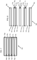
- a glass article 2 has a thickness 8, and includes a carrier 10 having a thickness 18, a thin sheet 20 (i.e., one having a thickness of ⁇ 300 micrometres, including but not limited to thicknesses of, for example, 10-50 micrometres, 50-100 micrometres, 100-150 micrometres, 150-300 micrometres, 300, 250, 200 190, 180, 170, 160, 150 140, 130, 120 110 100, 90, 80, 70, 60, 50, 40 30, 20, or 10, micrometres) having a thickness 28, and a surface modification layer 30 having a thickness 38.
- a carrier 10 having a thickness 18, a thin sheet 20 (i.e., one having a thickness of ⁇ 300 micrometres, including but not limited to thicknesses of, for example, 10-50 micrometres, 50-100 micrometres, 100-150 micrometres, 150-300 micrometres, 300, 250, 200 190, 180, 170, 160, 150 140, 130, 120 110 100, 90, 80, 70, 60, 50
- the glass article 2 is designed to allow the processing of thin sheet 20 in equipment designed for thicker sheets (i.e., those on the order of ⁇ .4mm, e.g., .4 mm, .5 mm, .6 mm, .7 mm, .8 mm, .9 mm, or 1.0 mm) although the thin sheet 20 itself is ⁇ 300 micrometres. That is, the thickness 8, which is the sum of thicknesses 18, 28, and 38, is designed to be equivalent to that of the thicker sheet for which a piece of equipment-for example, equipment designed to dispose electronic device components onto substrate sheets-was designed to process.
- thickness 18 would be selected as 400 micrometres, assuming that thickness 38 is negligible. That is, the surface modification layer 30 is not shown to scale; instead, it is greatly exaggerated for sake of illustration only. Additionally, the surface modification layer is shown in cut-away. In actuality, the surface modification layer would be disposed uniformly over the bonding surface 14 when providing a reusable carrier.
- thickness 38 will be on the order of nanometers, for example 0.1 to 2.0, or up to 10 nm, and in some instances may be up to 100 nm. The thickness 38 may be measured by ellipsometer.
- the presence of a surface modification layer may be detected by surface chemistry analysis, for example by ToF Sims mass spectrometry. Accordingly, the contribution of thickness 38 to the article thickness 8 is negligible and may be ignored in the calculation for determining a suitable thickness 18 of carrier 10 for processing a given thin sheet 20 having a thickness 28. However, to the extent that surface modification layer 30 has any significant thickness 38, such may be accounted for in determining the thickness 18 of a carrier 10 for a given thickness 28 of thin sheet 20, and a given thickness for which the processing equipment was designed.
- Carrier 10 has a first surface 12, a bonding surface 14, a perimeter 16, and thickness 18. Further, the carrier 10 comprises glass, ceramic, glass-ceramic, or metal (as the surface energy and/or bonding may be controlled in a manner similar to that described below in connection with a glass carrier). If made of glass, carrier 10 may be of any suitable composition including alumino-silicate, boro-silicate, alumino-boro-silicate, soda-lime-silicate, and may be either alkali containing or alkali-free depending upon its ultimate application.
- Thickness 18 may be from about 0.2 to 3 mm, or greater, for example 0.2, 0.3, 0.4, 0.5, 0.6, 0.65, 0.7, 1.0, 2.0, or 3 mm, or greater, and will depend upon the thickness 28, and thickness 38 when such is non-negligible, as noted above.
- the carrier 10 may be made of one layer, as shown, or multiple layers (including multiple thin sheets) that are bonded together. Further, the carrier may be of a Gen 1 size or larger, for example, Gen 2, Gen 3, Gen 4, Gen 5, Gen 8 or larger (e.g., sheet sizes from 100 mm x 100 mm to 3 meters x 3 meters or greater).
- the thin sheet 20 has a first surface 22, a bonding surface 24, a perimeter 26, and thickness 28. Perimeters 16 and 26 may be of any suitable shape, may be the same as one another, or may be different from one another. Further, the thin sheet 20 comprises glass, ceramic, or glass-ceramic. When made of glass, thin sheet 20 may be of any suitable composition, including alumino-silicate, boro-silicate, alumino-boro-silicate, soda-lime-silicate, and may be either alkali containing or alkali free depending upon its ultimate application. The coefficient of thermal expansion of the thin sheet could be matched relatively closely with that of the carrier to prevent warping of the article during processing at elevated temperatures.
- the thickness 28 of the thin sheet 20 is 300 micrometres or less, as noted above.
- the thin sheet may be of a Gen 1 size or larger, for example, Gen 2, Gen 3, Gen 4, Gen 5, Gen 8 or larger (e.g., sheet sizes from 100 mm x 100 mm to 3 meters x 3 meters or greater).
- flat panel display (FPD) processing may include wet ultrasonic, vacuum, and high temperature (e.g., ⁇ 400°C), processing.
- FPD flat panel display
- the temperature may be ⁇ 500°C, or ⁇ 600°C, and up to 650°C.
- the bonding surface 14 In order to survive the harsh environment in which article 2 will be processed, as during FPD manufacture for example, the bonding surface 14 should be bonded to bonding surface 24 with sufficient strength so that the thin sheet 20 does not separate from carrier 10. And this strength should be maintained through the processing so that the thin sheet 20 does not separate from the carrier 10 during processing. Further, to allow the thin sheet 20 to be removed from carrier 10 (so that carrier 10 may be reused), the bonding surface 14 should not be bonded to bonding surface 24 too strongly either by the initially designed bonding force, and/or by a bonding force that results from a modification of the initially designed bonding force as may occur, for example, when the article undergoes processing at high temperatures, e.g., temperatures of ⁇ 400°C.
- the surface modification layer 30 may be used to control the strength of bonding between bonding surface 14 and bonding surface 24 so as to achieve both of these objectives.
- the controlled bonding force is achieved by controlling the contributions of van der Waals (and/or hydrogen bonding) and covalent attractive energies to the total adhesion energy which is controlled by modulating the polar and non-polar surface energy components of the thin sheet 20 and the carrier 10.
- This controlled bonding is strong enough to survive FPD processing (including wet, ultrasonic, vacuum, and thermal processes including temperatures ⁇ 400°C, and in some instances, processing temperatures of ⁇ 500°C, or ⁇ 600°C, and up to 650°C.) and remain de-bondable by application of sufficient separation force and yet by a force that will not cause catastrophic damage to the thin sheet 20 and/or the carrier 10.
- FPD processing including wet, ultrasonic, vacuum, and thermal processes including temperatures ⁇ 400°C, and in some instances, processing temperatures of ⁇ 500°C, or ⁇ 600°C, and up to 650°C.
- Such de-bonding permits removal of thin sheet 20 and the devices fabricated thereon, and also allows for re-use of the carrier 10.
- the surface modification layer 30 is shown as a solid layer between thin sheet 20 and carrier 10, such need not be the case.
- the layer 30 may be on the order of 0.1 to 2 nm thick, and may not completely cover every bit of the bonding surface 14.
- the coverage may be ⁇ 100%, from 1% to 100%, from 10% to 100%, from 20% to 90%, or from 50% to 90%.
- the layer 30 maybe up to 10 nm thick, or in other embodiments even up to 100 nm thick.
- the surface modification layer 30 may be considered to be disposed between the carrier 10 and thin sheet 20 even though it may not contact one or the other of the carrier 10 and thin sheet 20.
- an important aspect of the surface modification layer 30 is that it modifies the ability of the bonding surface 14 to bond with bonding surface 24, thereby controlling the strength of the bond between the carrier 10 and the thin sheet 20.
- the material and thickness of the surface modification layer 30, as well as the treatment of the bonding surfaces 14, 24 prior to bonding, can be used to control the strength of the bond (energy of adhesion) between carrier 10 and thin sheet 20.
- ⁇ 12 ⁇ 1 + ⁇ 2 ⁇ 2 ⁇ 1 d ⁇ 2 d ⁇ 2 ⁇ 1 p ⁇ 2 p
- the energy of adhesion could be approximately calculated as: W ⁇ 2 ⁇ ⁇ 1 d ⁇ 2 d + ⁇ 1 p ⁇ 2 p ⁇
- the covalent adhesion energy is rather common, as in silicon wafer bonding where an initially hydrogen bonded pair of wafers are heated to a higher temperature to convert much or all the silanol-silanol hydrogen bonds to Si-O-Si covalent bonds. While the initial, room temperature, hydrogen bonding produces an adhesion energy of the order of ⁇ 100-200mJ/m 2 which allows separation of the bonded surfaces, a fully covalently bonded wafer pair as achieved during high temperature processing (on the order of 400 to 800 °C) has adhesion energy of ⁇ 1000-3000 mJ/m 2 which does not allow separation of the bonded surfaces; instead, the two wafers act as a monolith.
- the adhesion energy would be that of the coating material, and would be very low leading to low or no adhesion between the bonding surfaces 14, 24, whereby the thin sheet 20 would not be able to be processed on carrier 10.
- the inventors have found various manners of providing a surface modification layer 30 leading to an adhesion energy that is between these two extremes, and such that there can be produced a controlled bonding that is sufficient enough to maintain a pair of glass substrates (for example a glass carrier 10 and a thin glass sheet 20) bonded to one another through the rigors of FPD processing but also of a degree that (even after high temperature processing of, e.g. ⁇ 400°C) allows the detachment of the thin sheet 20 from the carrier 10 after processing is complete.
- the detachment of the thin sheet 20 from the carrier 10 can be performed by mechanical forces, and in such a manner that there is no catastrophic damage to at least the thin sheet 20, and preferably also so that there is no catastrophic damage to the carrier 10.
- Equation (5) describes that the adhesion energy is a function of four surface energy parameters plus the covalent and electrostatic energy, if any.
- An appropriate adhesion energy can be achieved by judicious choice of surface modifiers, i.e., of surface modification layer 30, and/or thermal treatment of the surfaces prior to bonding.
- the appropriate adhesion energy may be attained by the choice of chemical modifiers of either one or both of bonding surface 14 and bonding surface 24, which in turn control both the van der Waal (and/or hydrogen bonding, as these terms are used interchangeably throughout the specification) adhesion energy as well as the likely covalent bonding adhesion energy resulting from high temperature processing (e.g., on the order of ⁇ 400°C).
- Control of the initial van der Waals (and/or hydrogen) bonding at room temperature is performed so as to provide a bond of one surface to the other to allow vacuum and or spin-rinse-dry (SRD) type processing, and in some instances also an easily formed bond of one surface to the other-wherein the easily formed bond can be performed at room temperature without application of externally applied forces over the entire area of the thin sheet 20 as is done in pressing the thin sheet 20 to the carrier 10 with a squeegee, or with a reduced pressure environment. That is, the initial van der Waals bonding provides at least a minimum degree of bonding holding the thin sheet and carrier together so that they do not separate if one is held and the other is allowed to be subjected to the force of gravity.
- SRD spin-rinse-dry
- the initial van der Walls (and/or hydrogen) bonding will be of such an extent that the article may also go through vacuum, SRD, and ultrasonic processing without the thin sheet delaminating from the carrier.
- This precise control of both van der Waal (and/or hydrogen bonding) and covalent interactions at appropriate levels via surface modification layer 30 (including the materials from which it is made and/or the surface treatment of the surface to which it is applied), and/or by heat treatment of the bonding surfaces prior to bonding them together achieves the desired adhesion energy that allows thin sheet 20 to bond with carrier 10 throughout FPD style processing, while at the same time, allowing the thin sheet 20 to be separated (by an appropriate force avoiding damage to the thin sheet 20 and/or carrier) from the carrier 10 after FPD style processing.
- electrostatic charge could be applied to one or both glass surfaces to provide another level of control of the adhesion energy.
- FPD processing for example p-Si and oxide TFT fabrication typically involve thermal processes at temperatures above 400°C, above 500°C, and in some instances at or above 600°C, up to 650°C which would cause glass to glass bonding of a thin glass sheet 20 with a glass carrier 10 in the absence of surface modification layer 30. Therefore controlling the formation of Si-O-Si bonding leads to a reusable carrier.
- One method of controlling the formation of Si-O-Si bonding at elevated temperature is to reduce the concentration of surface hydroxyls on the surfaces to be bonded.
- FIG. 3 which is Iler's plot ( R. K. Iller: The Chemistry of Silica (Wiley-Interscience, New York, 1979 ) of surface hydroxyl concentration on silica as a function of temperature, the number of hydro xyls (OH groups) per square nm decreases as the temperature of the surface increases.
- heating a silica surface and by analogy a glass surface, for example bonding surface 14 and/or bonding surface 24
- reduces the concentration of surface hydroxyls decreasing the probability that hydroxyls on two glass surfaces will interact.
- This reduction of surface hydroxyl concentration in turn reduces the Si-O-Si bonds formed per unit area, lowering the adhesive force.
- a controlled bonding area that is, a bonding area that provides a sufficient room-temperature bond between the thin sheet 20 and carrier 10 to allow the article 2 to be processed in FPD type processes (including vacuum and wet processes), and yet one that controls covalent bonding between the thin sheet 20 and carrier 10 (even at elevated temperatures ⁇ 400°C) so as to allow the thin sheet 20 to be removed from the carrier 10 (without damage to at least the thin sheet, and preferably without damage to the carrier also) after the article 2 has finished high temperature processing, for example, FPD type processing or LTPS processing.
- the following five tests were used to evaluate the likelihood that a particular bonding surface preparation and surface modification layer 30 would allow a thin sheet 20 to remain bonded to a carrier 10 throughout FPD processing, while allowing the thin sheet 20 to be removed from the carrier 10 (without damaging the thin sheet 20 and/or the carrier 10) after such processing (including processing at temperatures ⁇ 400°C).
- the tests were performed in order, and a sample progressed from one test to the next unless there was failure of the type that would not permit the subsequent testing.
- the benefit of modifying one or more of the bonding surfaces 14, 24 with a surface modification layer 30 so the article 2 is capable of successfully undergoing FPD processing was demonstrated by processing articles 2 having glass carriers 10 and thin glass sheets 20 without a surface modification layer 30 therebetween. Specifically, first there was tried preparation of the bonding surfaces 14, 24 by heating to reduce hydroxyl groups, but without a surface modification layer 30. The carriers 10 and thin sheets 20 were cleaned, the bonding surfaces 14 and 24 were bonded to one another, and then the articles 2 were tested.
- a typical cleaning process for preparing glass for bonding is the SC1 cleaning process where the glass is cleaned in a dilute hydrogen peroxide and base (commonly ammonium hydroxide, but tetramethylammonium hydroxide solutions for example JT Baker JTB-100 or JTB-111 may also be used). Cleaning removes particles from the bonding surfaces, and makes the surface energy known, i.e., it provides a base-line of surface energy.
- the manner of cleaning need not be SC1, other types of cleaning may be used, as the type of cleaning is likely to have only a very minor effect on the silanol groups on the surface. The results for various tests are set forth below in Table 1.
- a strong but separable initial, room temperature or van der Waal and/or Hydrogen-bond was created by simply cleaning a thin glass sheet of 100mm square x 100 micron thick, and a glass carrier 150mm diameter single mean flat (SMF) wafer 0.50 or 0.63 mm thick, each comprising Eagle XG® display glass (an alkali-free, alumino-boro-silicate glass, having an average surface roughness Ra on the order of 0.2 nm, available from Corning Incorporated, Corning, NY).
- SMF single mean flat
- Eagle XG® display glass an alkali-free, alumino-boro-silicate glass, having an average surface roughness Ra on the order of 0.2 nm, available from Corning Incorporated, Corning, NY.
- glass was cleaned 10 min in a 65°C bath of 40:1:2 DI water: JTB-111:Hydrogen peroxide.
- the thin glass or glass carrier may or may not have been annealed in nitrogen for 10min at 400°C to remove residual water - the notation "400°C" in the "Carrier” column or the “Thin Glass” column in Table 1 below indicates that the sample was annealed in nitrogen for 10 minutes at 400 °C.
- FPD process compatibility testing demonstrates this SC1-SC1 initial, room temperature, bond is mechanically strong enough to pass vacuum, SRD and ultrasonic testing. However, heating at 400°C and above created a permanent bond between the thin glass and carrier, i.e., the thin glass sheet could not be removed from the carrier without damaging either one or both of the thin glass sheets and carrier.
- Example 1c wherein each of the carrier and the thin glass had an annealing step to reduce the concentration of surface hydroxyls. Accordingly, the above-described preparation of the bonding surfaces 14, 24 via heating alone and then bonding of the carrier 10 and the thin sheet 12, without a surface modification layer 30, is not a suitable controlled bond for FPD processes wherein the temperature will be ⁇ 400°C.
- Table 1 - process compatibility testing of SC1-treated glass bonding surfaces Example Carrier Thin Glass Vacuum SRD 400C 600C Ultrasonic 1a SC1 SC1 P P F F P 1b SC1, 400C SC1 P P F F P 1c SC1, 400C SC1, 400C P P F F P
- Hydroxyl reduction as by heat treatment for example, and a surface modification layer 30 may be used together to control the interaction of bonding surfaces 14, 24.
- the bonding energy both van der Waals and/or Hydrogen-bonding at room temperature due to the polar/dispersion energy components, and covalent bonding at high temperature due to the covalent energy component
- the bonding energy of the bonding surfaces 14, 24 can be controlled so as to provide varying bond strength from that wherein room-temperature bonding is difficult, to that allowing easy room-temperature bonding and separation of the bonding surfaces after high temperature processing, to that which-after high temperature processing-prevents the surfaces from separating without damage.
- the surface modification layer may be used to control room temperature bonding by which the thin sheet and carrier are initially put together, whereas the reduction of hydroxyl groups on the surface (as by heating the surface, or by reaction of the hydroxyl groups with the surface modification layer, for example) may be used to control the covalent bonding, particularly that at high temperatures.
- a material for the surface modification layer 30 may provide a bonding surface 14, 24 with an energy (for example, and energy ⁇ 40 mJ/m 2 , as measured for one surface, and including polar and dispersion components) whereby the surface produces only weak bonding.
- an energy for example, and energy ⁇ 40 mJ/m 2 , as measured for one surface, and including polar and dispersion components
- HMDS hexamethyldisilazane
- TMS trimethylsilyl
- HMDS as a surface modification layer may be used together with surface heating to reduce the hydroxyl concentration to control both room temperature and high temperature bonding.
- HMDS treatment of just one surface creates stronger room temperature adhesion which survives vacuum and SRD processing.
- thermal processes at 400°C and above permanently bonded the thin glass to the carrier.
- the maximum surface coverage of the trimethylsilyl groups on silica has been calculated by Sindorf and Maciel in J. Phys. Chem. 1982, 86, 5208-5219 to be 2.8/nm 2 and measured by Suratwala et. al. in Journal of Non-Crystalline Solids 316 (2003) 349-363 as 2.7/nm 2 , vs. a hydroxyl concentration of 4.6-4.9/nm 2 for fully hydroxylated silica. That is, although the trimethylsilyl groups do bond with some surface hydroxyls, there will remain some un-bonded hydroxyls. Thus one would expect condensation of surface silanol groups to permanently bond the thin glass and carrier given sufficient time and temperature.
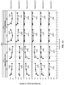
- FIG. 4 shows the surface energy of an Eagle XG® display glass carrier after annealing, and after HMDS treatment. Increased annealing temperature prior to HMDS exposure increases the total (polar and dispersion) surface energy (line 402) after HMDS exposure by increasing the polar contribution (line 404). It is also seen that the dispersion contribution (line 406) to the total surface energy remains largely unchanged by the heat treatment.
- the thin glass sheet was heated at a temperature of 150°C in a vacuum for one hour prior to bonding with the non-heat-treated carrier having a coating of HMDS. This heat treatment of the thin glass sheet was not sufficient to prevent permanent bonding of the thin glass sheet to the carrier at temperatures ⁇ 400°C.
- varying the annealing temperature of the glass surface prior to HMDS exposure can vary the bonding energy of the glass surface so as to control bonding between the glass carrier and the thin glass sheet.
- the carrier was annealed at a temperature of 190°C in vacuum for 1 hour, followed by HMDS exposure to provide surface modification layer 30. Additionally, the thin glass sheet was annealed at 450°C in a vacuum for 1 hour before bonding with the carrier.
- the resulting article survived the vacuum, SRD, and 400°C tests (parts a and c, but did not pass part b as there was increased bubbling), but failed the 600°C test. Accordingly, although there was increased resistance to high temperature bonding as compared with example 2b, this was not sufficient to produce an article for processing at temperatures ⁇ 600°C (for example LTPS processing) wherein the carrier is reusable.
- the carrier was annealed at a temperature of 340°C in a vacuum for 1 hour, followed by HMDS exposure to provide surface modification layer 30. Again, the thin glass sheet was annealed at 450°C for 1 hour in a vacuum before bonding with the carrier.
- the results were similar to those for example 2c, wherein the article survived the vacuum, SRD, and 400°C tests (parts a and c, but did not pass part b as there was increased bubbling), but failed the 600°C test.
- annealing both thin glass and carrier at 450°C in vacuum for 1 hr, followed by HMDS exposure of the carrier, and then bonding of the carrier and thin glass sheet improves the temperature resistance to permanent bonding.
- An anneal of both surfaces to 450°C prevents permanent bonding after RTP annealing at 600°C for 10 min, that is, this sample passed the 600°C processing test (parts a and c, but did not pass part b as there was increased bubbling; a similar result was found for the 400°C test).
- each of the carrier and the thin sheet were Eagle XG® glass, wherein the carrier was a 150 mm diameter SMF wafer 630 micrometres thick and the thin sheet was 100 mm square 100 micrometres thick
- the HMDS was applied by pulse vapor deposition in a YES-5 HMDS oven (available from Yield Engineering Systems, San Jose CA) and was one atomic layer thick (i.e., about 0.2 to 1 nm), although the surface coverage may be less than one monolayer, i.e., some of the surface hydroxyls are not covered by the HMDS as noted by Maciel and discussed above. Because of the small thickness in the surface modification layer, there is little risk of outgassing which can cause contamination in the device fabrication. Also, as indicated in Table 2 by the "SC1" notation, each of the carriers and thin sheets were cleaned using an SC1 process prior to heat treating or any subsequent HMDS treatment.
- a comparison of example 2a with example 2b shows that the bonding energy between the thin sheet and the carrier can be controlled by varying the number of surfaces which include a surface modification layer. And controlling the bonding energy can be used to control the bonding force between two bonding surfaces. Also, a comparison of examples 2b-2e, shows that the bonding energy of a surface can be controlled by varying the parameters of a heat treatment to which the bonding surface is subjected before application of a surface modification material. Again, the heat treatment can be used to reduce the number of surface hydroxyls and, thus, control the degree of covalent bonding, especially that at high temperatures.
- a reusable carrier can also be created if one or both bonding surfaces are modified to create a moderate bonding force with a surface modification layer that either covers, or sterically hinders species for example hydroxyls to prevent the formation at elevated temperature of strong permanent covalent bonds between carrier and thin sheet.
- a surface modification layer that either covers, or sterically hinders species for example hydroxyls to prevent the formation at elevated temperature of strong permanent covalent bonds between carrier and thin sheet.
- One way to create a tunable surface energy, and cover surface hydroxyls to prevent formation of covalent bonds is deposition of plasma polymer films, for example fluoropolymer films.
- Plasma polymerization deposits a thin polymer film under atmospheric or reduced pressure and plasma excitation (DC or RF parallel plate, Inductively Coupled Plasma (ICP) Electron Cyclotron Resonance (ECR) downstream microwave or RF plasma) from source gases for example fluorocarbon sources (including CF4, CHF3, C2F6, C3F6, C2F2, CH3F, C4F8, chlorofluoro carbons, or hydrochlorofluoro carbons), hydrocarbons for example alkanes (including methane, ethane, propane, butane), alkenes (including ethylene, propylene), alkynes (including acetylene), and aromatics (including benzene, toluene), hydrogen, and other gas sources for example SF6.
- Plasma polymerization creates a layer of highly cross-linked material. Control of reaction conditions and source gases can be used to control the film thickness, density, and chemistry to tailor the functional groups to the desired application.
- FIG. 5 shows the total (line 502) surface energy (including polar (line 504) and dispersion (line 506) components) of plasma polymerized fluoropolymer (PPFP) films deposited from CF4-C4F8 mixtures with an Oxford ICP380 etch tool (available from Oxford Instruments, Oxfordshire UK). The films were deposited onto a sheet of Eagle XG ® glass, and spectroscopic ellipsometry showed the films to be 1-10 nm thick. As seen from FIG. 5 , glass carriers treated with plasma polymerized fluoropolymer films containing less than 40% C4F8 exhibit a surface energy >40 mJ/m 2 and produce controlled bonding between the thin glass and carrier at room temperature by van der Waal or hydrogen bonding.
- PPFP plasma polymerized fluoropolymer
- each of the carrier and the thin sheet were Eagle XG® glass, wherein the carrier was a 150 mm diameter SMF wafer 630 micrometres thick and the thin sheet was 100 mm square 100 micrometres thick. Because of the small thickness in the surface modification layer, there is little risk of outgassing which can cause contamination in the device fabrication. Further, because the surface modification layer did not appear to degrade, again, there is even less risk of outgassing. Also, as indicated in Table 3, each of the thin sheets was cleaned using an SC1 process prior to heat treating at 150°C for one hour in a vacuum.
- Still other materials may be used as the surface modification layer to control the room temperature and high temperature bonding forces between the thin sheet and the carrier.
- a bonding surface that can produce controlled bonding can be created by silane treating a glass carrier and/or glass thin sheet.
- Silanes are chosen so as to produce a suitable surface energy, and so as to have sufficient thermal stability for the application.
- the carrier or thin glass to be treated may be cleaned by a process for example O2 plasma or UV-ozone, and SC1 or standard clean two (SC2, as is known in the art) cleaning to remove organics and other impurities (metals, for example) that would interfere with the silane reacting with the surface silanol groups.
- Washes based on other chemistries may also be used, for example, HF, or H2SO4 wash chemistries.
- the carrier or thin glass may be heated to control the surface hydroxyl concentration prior to silane application (as discussed above in connection with the surface modification layer of HMDS), and/or may be heated after silane application to complete silane condensation with the surface hydroxyls.
- concentration of unreacted hydroxyl groups after silanization may be made low enough prior to bonding as to prevent permanent bonding between the thin glass and carrier at temperatures ⁇ 400°C, that is, to form a controlled bond. This approach is described below.
- a glass carrier with its bonding surface O2 plasma and SC1 treated was then treated with 1% dodecyltriethoxysilane (DDTS) in toluene, and annealed at 150°C in vacuum for 1 hr to complete condensation.
- DDTS treated surfaces exhibit a surface energy of 45 mJ/m2.
- Table 4 a glass thin sheet (having been SC1 cleaned and heated at 400°C in a vacuum for one hour) was bonded to the carrier bonding surface having the DDTS surface modification layer thereon. This article survived wet and vacuum process tests but did not survive thermal processes over 400°C without bubbles forming under the carrier due to thermal decomposition of the silane.
- a glass carrier with its bonding surface O2 plasma and SC1 treated was then treated with 1% 3,3,3, trifluoropropyltritheoxysilane (TFTS) in toluene, and annealed at 150°C in vacuum for 1 hr to complete condensation.
- TFTS treated surfaces exhibit a surface energy of 47 mJ/m 2 .
- Table 4 a glass thin sheet (having been SC1 cleaned and then heated at 400°C in a vacuum for one hour) was bonded to the carrier bonding surface having the TFTS surface modification layer thereon. This article survived the vacuum, SRD, and 400°C process tests without permanent bonding of the glass thin sheet to the glass carrier.
- the 600°C test produced bubbles forming under the carrier due to thermal decomposition of the silane. This was not unexpected because of the limited thermal stability of the propyl group. Although this sample failed the 600°C test due to the bubbling, the material and heat treatment of this example may be used for some applications wherein bubbles and the adverse effects thereof, for example reduction in surface flatness, or increased waviness, can be tolerated.
- a glass carrier with its bonding surface O2 plasma and SC1 treated was then treated with 1% phenyltriethoxysilane (PTS) in toluene, and annealed at 200°C in vacuum for 1 hr to complete condensation.
- PTS treated surfaces exhibit a surface energy of 54 mJ/m 2 .
- Table 4 a glass thin sheet (having been SC1 cleaned and then heated at 400°C in a vacuum for one hour) was bonded to the carrier bonding surface having the PTS surface modification layer. This article survived the vacuum, SRD, and thermal processes up to 600°C without permanent bonding of the glass thin sheet with the glass carrier.
- a glass carrier with its bonding surface O2 plasma and SC1 treated was then treated with 1% diphenyldiethoxysilane (DPDS) in toluene, and annealed at 200°C in vacuum for 1 hr to complete condensation.
- DPDS treated surfaces exhibit a surface energy of 47 mJ/m 2 .
- Table 4 a glass thin sheet (having been SC1 cleaned and then heated at 400°C in a vacuum for one hour) was bonded to the carrier bonding surface having the DPDS surface modification layer. This article survived the vacuum and SRD tests, as well as thermal processes up to 600°C without permanent bonding of the glass thin sheet with the glass carrier
- a glass carrier having its bonding surface O2 plasma and SC1 treated was then treated with 1% 4-pentafluorophenyltriethoxysilane (PFPTS) in toluene, and annealed at 200°C in vacuum for 1 hr to complete condensation.
- PFPTS treated surfaces exhibit a surface energy of 57 mJ/m 2 .
- Table 4 a glass thin sheet (having been SC1 cleaned and then heated at 400°C in a vacuum for one hour) was bonded to the carrier bonding surface having the PFPTS surface modification layer. This article survived the vacuum and SRD tests, as well as thermal processes up to 600°C without permanent bonding of the glass thin sheet with the glass carrier.
- each of the carrier and the thin sheet were Eagle XG® glass, wherein the carrier was a 150 mm diameter SMF wafer 630 micrometres thick and the thin sheet was 100 mm square 100 micrometres thick.
- the silane layers were self-assembled monolayers (SAM), and thus were on the order of less than about 2 nm thick.
- SAM was created using an organosilane with an aryl or alkyl non-polar tail and a mono, di, or tri-alkoxide head group. These react with the silnaol surface on the glass to directly attach the organic functionality. Weaker interactions between the non-polar head groups organize the organic layer.
- each of the glass thin sheets was cleaned using an SC1 process prior to heat treating at 400°C for one hour in a vacuum.
- each carrier had a surface energy above 40 mJ/m 2 , which facilitated initial room temperature bonding so that the article survived vacuum and SRD processing.
- examples 4a and 4b did not pass 600°C processing test.
- examples 3 and 4 can be applied to the carrier, to the thin sheet, or to both the carrier and thin sheet surfaces that will be bonded together.
- controlled bonding via surface modification layers is to provide reuse of the carrier in an article undergoing processes requiring a temperature ⁇ 600°C, as in LTPS processing, for example.
- Surface modification layers including the materials and bonding surface heat treatments, as exemplified by the examples 2e, 3a, 3b, 4c, 4d, and 4e, above, maybe used to provide reuse of the carrier under such temperature conditions.
- these surface modification layers may be used to modify the surface energy of the area of overlap between the bonding areas of the thin sheet and carrier, whereby the entire thin sheet may be separated from the carrier after processing.
- the thin sheet may be separated all at once, or may be separated in sections as, for example, when first removing devices produced on portions of the thin sheet and thereafter removing the remaining portions to clean the carrier for reuse.
- the carrier can be reused as is by simply by placing another thin sheet thereon.
- the carrier may be cleaned and once again prepared to carry a thin sheet by forming a surface modification layer anew. Because the surface modification layers prevent permanent bonding of the thin sheet with the carrier, they may be used for processes wherein temperatures are ⁇ 600°C.
- these surface modification layers may control bonding surface energy during processing at temperatures ⁇ 600°C, they may also be used to produce a thin sheet and carrier combination that will withstand processing at lower temperatures, and may be used in such lower temperature applications to control bonding. Moreover, where the thermal processing of the article will not exceed 400°C, surface modification layers as exemplified by the examples 2c, 2d, 4b may also be used in this same manner.
- a second use of controlled bonding via surface modification layers is to provide a controlled bonding area, between a glass carrier and a glass thin sheet. More specifically, with the use of the surface modification layers an area of controlled bonding can be formed wherein a sufficient separation force can separate the thin sheet portion from the carrier without damage to either the thin sheet or the carrier caused by the bond, yet there is maintained throughout processing a sufficient bonding force to hold the thin sheet relative to the carrier.
- a glass thin sheet 20 may be bonded to a glass carrier 10 by a bonded area 40. In the bonded area 40, the carrier 10 and thin sheet 20 are covalently bonded to one another so that they act as a monolith.
- controlled bonding areas 50 having perimeters 52, wherein the carrier 10 and thin sheet 20 are connected, but may be separated from one another, even after high temperature processing, e.g. processing at temperatures ⁇ 600°C. Although ten controlled bonding areas 50 are shown in FIG. 6 , any suitable number, including one, may be provided.
- the surface modification layers 30, including the materials and bonding surface heat treatments, as exemplified by the examples 2a, 2e, 3a, 3b, 4c, 4d, and 4e, above, may be used to provide the controlled bonding areas 50 between the carrier 10 and the thin sheet 20. Specifically, these surface modification layers may be formed within the perimeters 52 of controlled bonding areas 50 either on the carrier 10 or on the thin sheet 20.
- the article 2 when the article 2 is processed at high temperature, either to form covalent bonding in the bonding area 40 or during device processing, there can be provided a controlled bond between the carrier 10 and the thin sheet 20 within the areas bounded by perimeters 52 whereby a separation force may separate (without catastrophic damage to the thin sheet or carrier) the thin sheet and carrier in this region, yet the thin sheet and carrier will not delaminate during processing, including ultrasonic processing.
- the controlled bonding of the present application as provided by the surface modification layers and any associated heat treatments, is thus able to improve upon the carrier concept in US '727.
- This problem can be eliminated by minimizing the gap between the thin glass and the carrier and by providing sufficient adhesion, or controlled bonding between the carrier 20 and thin glass 10 in these areas 50.
- Surface modification layers including materials and any associated heat treatments as exemplified by examples 2a, 2e, 3a, 3b, 4c, 4d, and 4e) of the bonding surfaces control the bonding energy so as to provide a sufficient bond between the thin sheet 20 and carrier 10 to avoid these unwanted vibrations in the controlled bonding region.
- the portions of thin sheet 20 within the perimeters 52 may simply be separated from the carrier 10 after processing and after separation of the thin sheet along perimeters 57.
- the surface modification layers control bonding energy to prevent permanent bonding of the thin sheet with the carrier, they may be used for processes wherein temperatures are ⁇ 600°C.
- these surface modification layers may control bonding surface energy during processing at temperatures ⁇ 600°C, they may also be used to produce a thin sheet and carrier combination that will withstand processing at lower temperatures, and may be used in such lower temperature applications.
- surface modification layers as exemplified by the examples 2c, 2d, 4b may also be used-in some instances, depending upon the other process requirements-in this same manner to control bonding surface energy.
- a third use of controlled bonding via surface modification layers is to provide a bonding area between a glass carrier and a glass thin sheet.
- a glass thin sheet 20 may be bonded to a glass carrier 10 by a bonded area 40.
- the bonded area 40, the carrier 10 and thin sheet 20 maybe covalently bonded to one another so that they act as a monolith. Additionally, there are controlled bonding areas 50 having perimeters 52, wherein the carrier 10 and thin sheet 20 are bonded to one another sufficient to withstand processing, and still allow separation of the thin sheet from the carrier even after high temperature processing, e.g. processing at temperatures ⁇ 600°C. Accordingly, surface modification layers 30 (including materials and bonding surface heat treatments) as exemplified by the examples 1a, 1b, 1c, 2b, 2c, 2d, 4a, and 4b above, may be used to provide the bonding areas 40 between the carrier 10 and the thin sheet 20.
- these surface modification layers and heat treatments may be formed outside of the perimeters 52 of controlled bonding areas 50 either on the carrier 10 or on the thin sheet 20. Accordingly, when the article 2 is processed at high temperature, or is treated at high temperature to form covalent bonds, the carrier and the thin sheet 20 will bond to one another within the bonding area 40 outside of the areas bounded by perimeters 52. Then, during extraction of the desired parts 56 having perimeters 57, when it is desired to dice the thin sheet 20 and carrier 10, the article may be separated along lines 5 because these surface modification layers and heat treatments covalently bond the thin sheet 20 with the carrier 10 so they act as a monolith in this area.
- the surface modification layers provide permanent covalent bonding of the thin sheet with the carrier, they may be used for processes wherein temperatures are ⁇ 600°C. Moreover, where the thermal processing of the article, or of the initial formation of the bonding area 40, will be ⁇ 400°C but less than 600°C, surface modification layers, as exemplified by the materials and heat treatments in example 4a may also be used in this same manner.
- the carrier 10 and thin sheet 20 may be bonded to one another by controlled bonding via various surface modification layers described above. Additionally, there are controlled bonding areas 50, having perimeters 52, wherein the carrier 10 and thin sheet 20 are bonded to one another sufficient to withstand processing, and still allow separation of the thin sheet from the carrier even after high temperature processing, e.g. processing at temperatures ⁇ 600°C.
- surface modification layers 30 may be used to provide the bonding areas 40 between the carrier 10 and the thin sheet 20.
- these surface modification layers and heat treatments may be formed outside of the perimeters 52 of controlled bonding areas 50, and may be formed either on the carrier 10 or on the thin sheet 20.
- the controlled bonding areas 50 may be formed with the same, or with a different, surface modification layer as was formed in the bonding area 40.
- surface modification layers 30 including materials and bonding surface heat treatments as exemplified by the examples 2c, 2d, 2e, 3a, 3b, 4b, 4c, 4d, 4e, above, may be used to provide the bonding areas 40 between the carrier 10 and the thin sheet 20.
- non-bonding regions in areas 50, wherein the non-bonding regions may be areas of increased surface roughness as described in US '727, or may be provided by surface modification layers as exemplified by example 2a.
- a fourth use of the above-described manners of controlling bonding is for bulk annealing of a stack of glass sheets.
- Annealing is a thermal process for achieving compaction of the glass. Compaction involves reheating a glass body to a temperature below the glass softening point, but above the maximum temperature reached in a subsequent processing step. This achieves structural rearrangement and dimensional relaxation in the glass prior to, rather than during, the subsequent processing.
- Annealing prior to subsequent processing is beneficial to maintain precise alignment and/or flatness in a glass body during the subsequent processing, as in the manufacture of flat panel display devices, wherein structures made of many layers need to be aligned with a very tight tolerance, even after being subject to high temperature environments. If the glass compacts in one high temperature process, the layers of the structures deposited onto the glass prior to the high temperature process may not align correctly with the layers of the structures deposited after the high temperature process.
- anneal a stack of glass sheets wherein selected ones of the glass sheets are prevented from permanently bonding with one another, while at the same time, allowing other ones of the glass sheets, or portions of those other glass sheets, e.g., their perimeters, to permanently bond with each other.
- the above-described manners of controlling bonding between glass sheets may be used to achieve the foregoing bulk annealing and/or selective bonding.
- a surface modification layer on at least one of the major surfaces facing that interface.
- FIG. 7 is a schematic side view of a stack 760 of glass sheets 770-772
- FIG. 8 is an exploded view thereof for purposes of further explanation.
- a stack 760 of glass sheets may include glass sheets 770-772, and surface modification layers 790 to control the bonding between the glass sheets 770-772. Additionally, the stack 760 may include cover sheets 780, 781 disposed on the top and bottom of the stack, and may include surface modification layers 790 between the covers and the adjacent glass sheets.
- each of the glass sheets 770-772 includes a first major surface 776 and a second major surface 778.
- the glass sheets may be made of any suitable glass material, for example, an alumino-silicate glass, a boro-silicate glass, or an alumino-boro-silicate glass. Additionally, the glass may be alkali containing, or may be alkali-free.
- Each of the glass sheets 770-772 may be of the same composition, or the sheets may be of different compositions. Further, the glass sheets may be of any suitable type. That is, for example, the glass sheets 770-772 may be all carriers as described above, may be all thin sheets as described above, or may alternately be carriers and thin sheets.
- any one glass sheet may include no surface modification layers, one surface modification layer, or two surface modification layers.
- sheet 770 includes no surface modification layers
- sheet 771 includes one surface modification layer 790 on its second major surface 778
- sheet 772 includes two surface modification layers 790 wherein one such surface modification layer is on each of its major surfaces 776, 778.
- the cover sheets 780, 781 may be any material that will suitably withstand (not only in terms of time and temperature, but also with respect to other pertinent considerations like outgassing, for example) the time-temperature cycle for a given process.
- the cover sheets maybe made of the same material as the glass sheets being processed.
- a surface modification layer 790 may be included between the glass sheet 771 and the cover sheet 781 and/or between the glass sheet 772 and the cover sheet 780, as appropriate.
- the surface modification layer When present between a cover and a glass sheet, the surface modification layer maybe on the cover (as shown with cover 781 and adjacent sheet 771), maybe on the glass sheet (as shown with cover 780 and sheet 772), or may be on both the cover and the adjacent sheet (not shown). Alternatively, if the cover sheets 780, 781 are present, but are of a material that will not bond with the adjacent sheets 772, 772, then surface modification layers 790 need not be present therebetween.
- an interface Between adjacent sheets in the stack, there is an interface.
- an interface i.e., there is an interface 791 between sheet 770 and sheet 771, and interface 792 between sheet 770 and sheet 772.
- a surface modification layer 790 In order to control bonding at a given interface 791, 792 between adjacent glass sheets, or at a given interface 793, 794 between a glass sheet and a cover sheet, there may be used a surface modification layer 790.
- a surface modification layer 790 there is present at each interface 791, 792, a surface modification layer 790 on at least one of the major surfaces facing that interface.
- the second major surface 778 of glass sheet 771 includes a surface modification layer 790 to control the bonding between sheet 771 and adjacent sheet 770.
- the first major surface 776 of sheet 770 could also include a surface modification layer790 thereon to control bonding with sheet 771, i.e., there may be a surface modification layer on each of the major surfaces facing any particular interface.
- the particular surface modification layer 790 (and any associated surface modification treatment - for example a heat treatment on a particular surface prior to application of a particular surface modification layer to that surface, or a surface heat treatment of a surface with which a surface modification layer may contact) at any given interface 791-794, may be selected for the major surfaces 776, 778 facing that particular interface 791-794 to control bonding between adjacent sheets and, thereby, achieve a desired outcome for a given time-temperature cycle to which the stack 760 is subjected.
- any particular interface for example interface 791
- bonding at any particular interface could be controlled using a material according to any one of the examples 2a, 2c, 2d, 2e, 3a, 3b, or 4b-4e, together with any associated surface preparation. More specifically, the first surface 776 of sheet 770 would be treated as the "Thin Glass” in Tables 2-4, whereas the second surface 778 of sheet 771, would treated as the "Carrier” in Tables 2-4, or vice versa.
- a suitable time-temperature cycle having a temperature up to 400°C, could then be chosen based on the desired degree of compaction, number of sheets in the stack, as well as size and thickness of the sheets, so as to achieve the requisite time-temperature throughout the stack.
- bonding at any particular interface could be controlled using a material according to any one of the examples 2a, 2e, 3a, 3b, 4c, 4d, 4e, together with any associated surface preparation. More specifically, the first surface 776 of sheet 770 would be treated as the "Thin Glass” in Tables 2-4, whereas the second surface 778 of sheet 771, would treated as the "Carrier” in Tables 2-4, or vice versa.
- a suitable time-temperature cycle having a temperature up to 600°C, could then be chosen based on the desired degree of compaction, number of sheets in the stack, as well as size and thickness of the sheets, so as to achieve the requisite time-temperature throughout the stack.
- the bonding at the interface between pairs of glass sheets to be formed into an article 2 could be controlled using: (i) a material according to any one of the examples 2c, 2d, 4b, together with any associated surface preparation, around the perimeter (or other desired bonding area 40) of the sheets 770, 771; and (ii) a material according to any one of the examples 2a, 2e, 3a, 3b, 4c, 4d, 4e, together with any associated surface preparation, on an interior area (i.e., an area interior of the perimeter as treated in (i), or in desired controlled bonding areas 50 where separation of one sheet from the other is desired) of the sheets 770, 771.
- device processing in the controlled bonding areas 50 could then be performed at temperatures up to 600°C.
- Materials and heat treatments could be appropriately selected for compatibility with one another.
- any of the materials 2c, 2d, or 4b could be used for the bonding areas 40 with a material according to example 2a for the controlled bonding areas.
- the heat treatment for the bonding areas and controlled bonding areas could be appropriately controlled to minimize the effect of heat treatment in one area adversely affecting the desired degree of bonding in an adjacent area.
- those sheets could be appropriately arranged into a the stack and then heated up to 400°C to bulk anneal all the sheets in the stack without them being permanently bonded to one another. Then, the stack could be heated up to 600°C to form covalent bonds in the desired bonding areas of a pair of adjacent sheets to form an article 2 having a pattern of bonding areas and controlled bonding areas.
- the bonding at the interface between one pair of sheets that are to be covalently bonded by bonding areas 40 to form an article 2, and another pair of such sheets forming a separate but adjacent article 2 could be controlled with the materials and associated heat treatments of examples 2a, 2e, 3a, 3b, 4c, 4d, 4e, so that adjacent articles 2 would not be covalently bonded to one another.
- the heating above about 400°C should be performed in an oxygen-free atmosphere when it is desired to prevent covalent bonding in the area of the HMDS. That is, if the HMDS is exposed to an amount of oxygen in the atmosphere (at a temperature above about 400°C) sufficient to oxidize the HMDS, the bonding in any such area where the HMDS has been oxidized will become covalent bonding between adjacent glass sheets.
- alkyl hydrocarbon silanes similarly can be affected by exposure to oxygen at higher temperatures, e.g., above about 400°C, e.g., ethyl, propyl, butyl, or steryl, silanes.
- oxygen free may mean an oxygen concentration of less than 1000 ppm by volume, more preferred less than 100 ppm by volume.
- individual sheets may be separated from the stack.
- the individual sheets can be treated (for example, by oxygen plasma, heating in an oxygen environment at a temperature ⁇ 400°C, or by chemical oxidation, SC1, or SC2) to remove the surface modification layer 790.
- the individual sheets can be used as desired, for example, as electronic device substrates, for example OLED, FPD, or PV devices).
- the above-described methods of bulk annealing, or bulk processing have the advantage of maintaining clean sheet surfaces in an economical manner. More specifically, the sheets do not need to be kept in a clean environment from start to finish, as in a clean-room annealing lehr. Instead, the stack can be formed in a clean environment, and then processed in a standard annealing lehr (i.e., one in which cleanliness is not controlled) without the sheet surfaces getting dirty with particles because there is no fluid flow between the sheets. Accordingly, the sheet surfaces are protected from the environment in which the stack of sheets is annealed.
- the stack of sheets can be easily transported to a further processing area (either in the same or a different facility) because the sheets maintain some degree of adhesion, yet remain separable from one another upon sufficient force without damaging the sheets. That is, a glass manufacturer (for example) can assemble and anneal a stack of glass sheets, and then ship the sheets as a stack wherein they remain together during shipping (without fear of them separating in transit), whereupon arriving at their destination the sheets may be separated from the stack by a customer who may use the sheets individually or in smaller groups. Once separation is desired, the stack of sheets can again be processed in a clean environment (after washing the stack as necessary).
- the fusion drawn glass composition was (in mole %): SiO2 (67.7), Al2O3 (11.0), B203 (9.8), CaO (8.7), MgO (2.3), SrO (0.5). Seven (7), 0.7 mm thick by 150 mm diameter, fusion drawn glass substrates were patterned by lithographic methods with 200 nm deep fiducials/verniers using HF.
- the 7 coated individual glass substrates were placed together to form a single, thick substrate (referred to as the "glass stack").
- the glass stack was annealed in a nitrogen purged tube furnace ramping from 30°C to 590°C over a 15 minute period, holding 30 minutes at 590°C, then ramping down to about 230°C over a 50 minute period, then removing the glass stack from the furnace and cooling to room temperature of about 30°C in about 10 minutes.
- the substrates were removed from the furnace and easily separated into individual sheets (i.e., the samples did not permanently bond, globally or locally) using a razor wedge.
- Compaction was measured on each individual substrate by comparing the glass fiducials to a non-annealed quartz reference. The individual substrates were found to compact about 185 ppm. Two of the substrates as individual samples (not stacked together) went through a second anneal cycle as described above (590°C/30 minute hold). Compaction was measured again and the substrates were found to further compact less than 10 ppm (actually 0 to 2.5 ppm) due to the second heat treatment (change in glass dimensions-as compared with original glass dimension-after the second heat treatment minus the change in glass dimensions after the first heat treatment).
- individual glass sheets can be coated, stacked, heat treated at a high temperature to achieve compaction, cooled, separated into individual sheets and have ⁇ 10 ppm, and even ⁇ 5 ppm in dimension change (as compared to their size after the first heat treatment) after a second heat treatment.
- annealing furnaces may also be purged with other gasses including, air, argon, oxygen, CO2, or combinations thereof, depending upon the annealing temperature, and the stability of the surface modification layer material at those temperatures in a particular environment.
- the furnace in the above-described annealing could be a vacuum environment.
- the glass may be annealed in a spool, instead of sheet, form. That is, a suitable surface modification layer may be formed on one or both sides of a glass ribbon, and the ribbon then rolled. The entire roll could be subject to the same treatment as noted above for sheets, whereupon the glass of the entire spool would be annealed without sticking one wrap of the glass to an adjacent one. Upon un-rolling, the surface modification layer may be removed by any suitable process.
- Polymer adhesives used in typical wafer bonding applications are generally 10-100 micrometres thick and lose about 5% of their mass at or near their temperature limit.
- mass-spectrometry evolved from thick polymer films, it is easy to quantify the amount of mass loss, or outgassing, by mass-spectrometry.
- mass-spectrometry it is more challenging to measure the outgassing from thin surface treatments that are on the order of 10 nm thick or less, for example the plasma polymer or self-assembled monolayer surface modification layers described above, as well as for a thin layer of pyrolyzed silicone oil.
- mass-spectrometry is not sensitive enough. There are a number of other ways to measure outgassing, however.
- a first manner of measuring small amounts of outgassing is based on surface energy measurements, and will be described with reference to FIG. 9 .
- a setup as shown in FIG. 9 may be used.
- a first substrate, or carrier, 900 having the to-be-tested surface modification layer thereon presents a surface 902, i.e., a surface modification layer corresponding in composition and thickness to the surface modification layer 30 to be tested.
- a second substrate, or cover, 910 is placed so that its surface 912 is in close proximity to the surface 902 of the carrier 900, but not in contact therewith.
- the surface 912 is an uncoated surface, i.e., a surface of bare material from which the cover is made.
- Spacers 920 are placed at various points between the carrier 900 and cover 910 to hold them in spaced relation from one another.
- the spacers 920 should be thick enough to separate the cover 910 from the carrier 900 to allow a movement of material from one to the other, but thin enough so that during testing the amount of contamination from the chamber atmosphere on the surfaces 902 and 912 is minimized.
- the surface energy of bare surface 912 is measured, as is the surface energy of the surface 902, i.e., the surface of carrier 900 having the surface modification layer provided thereon.
- the surface energies as shown in FIG. 10 were measured by fitting a theoretical model developed by S. Wu (1971) to three contact angles of three test liquids; water, diiodomethane and hexadecane. (Reference: S. Wu, J. Polym. Sci. C, 34, 19, 1971 ).
- test article 901 is placed into a heating chamber 930, and is heated through a time-temperature cycle.
- the heating is performed at atmospheric pressure and under flowing N2 gas, i.e., flowing in the direction of arrows 940 at a rate of 2 standard liters per minute.
- changes in the surface 902 are evidenced by a change in the surface energy of surface 902.
- a change in the surface energy of surface 902 by itself does not necessarily mean that the surface modification layer has outgassed, but does indicate a general instability of the material at that temperature as its character is changing due to the mechanisms noted above, for example.
- the less the change in surface energy of surface 902 the more stable the surface modification layer.
- any material outgassed from surface 902 will be collected on surface 912 and will change the surface energy of surface 912. Accordingly, the change in surface energy of surface 912 is a proxy for outgassing of the surface modification layer present on surface 902.
- one test for outgassing uses the change in surface energy of the cover surface 912. Specifically, if there is a change in surface energy-of surface 912-of ⁇ 10 mJ/m2, then there is outgassing. Changes in surface energy of this magnitude are consistent with contamination which can lead to loss of film adhesion or degradation in material properties and device performance. A change in surface energy of ⁇ 5 mJ/m2 is close to the repeatability of surface energy measurements and inhomogeneity of the surface energy. This small change is consistent with minimal outgassing.
- the carrier 900, the cover 910, and the spacers 920 were made of Eagle XG glass, an alkali-free alumino-boro-silicate display-grade glass available from Corning Incorporated, Corning, NY, although such need not be the case.
- the carrier 900 and cover 910 were 150mm diameter 0.63mm thick.
- the carrier 910 and cover 920 will be made of the same material as carrier 10 and thin sheet 20, respectively, for which an outgassing test is desired.
- silicon spacers 0.63 mm thick, 2mm wide, and 8cm long, thereby forming a gap of 0.63 mm between surfaces 902 and 912.
- the chamber 930 was incorporated in MPT-RTP600s rapid thermal processing equipment that was cycled from room temperature to the test limit temperature at a rate of 9.2°C per minute, held at the test limit temperature for varying times as shown in the graphs as "Anneal Time", and then cooled at furnace rate to 200°C. After the oven had cooled to 200°C, the test article was removed, and after the test article had cooled to room temperature, the surface energies of each surface 902 and 912 were again measured.
- the data for the change in cover surface energy, tested to a limit temperature of 450°C, for Material #1, line 1003 the data was collected as follows.
- the data point at 0 minutes shows a surface energy of 75 mJ/m2 (milli-Joules per square meter), and is the surface energy of the bare glass, i.e., there has been no time-temperature cycle yet run.
- the data point at one minute indicates the surface energy as measured after a time-temperature cycle performed as follows: the article 901 (having Material #1 used as a surface modification layer on the carrier 900 to present surface 902) was placed in a heating chamber 930 at room temperature, and atmospheric pressure; the chamber was heated to the test-limit temperature of 450°C at a rate of 9.2°C per minute, with a N2 gas flow at two standard liters per minute, and held at the test-limit temperature of 450°C for 1 minute; the chamber was then allowed to cool to 300°C at a rate of 1°C per minute, and the article 901 was then removed from the chamber 930; the article was then allowed to cool to room temperature (without N2 flowing atmosphere); the surface energy of surface 912 was then measured and
- Material #1 is a CHF3-CF4 plasma polymerized fluoropolymer. This material is consistent with the surface modification layer in example 3b, above. As shown in FIG. 10 , lines 1001 and 1002 show that the surface energy of the carrier did not significantly change. Thus, this material is very stable at temperatures from 450°C to 600°C. Additionally, as shown by the lines 1003 and 1004, the surface energy of the cover did not significantly change either, i.e., the change is ⁇ 5mJ/m2. Accordingly, there was no outgassing associated with this material from 450°C to 600°C.
- Material #2 is a phenylsilane, a self-assembled monolayer (SAM) deposited form 1% toluene solution of phenyltriethoxysilane and cured in vacuum oven 30 minutes at 190°C.
- SAM self-assembled monolayer
- Material #3 is a pentafluorophenylsilane, a SAM deposited from 1% toluene solution of pentafluorophenyltriethoxysilane and cured in vacuum oven 30 minutes at 190°C. This material is consistent with the surface modification layer in example 4e, above. As shown in FIG. 10 , lines 1301 and 1302 indicate some change in surface energy on the carrier. As noted above, this indicates some change in the surface modification layer, and comparatively, Material #3 is somewhat less stable than Material #1. However, as noted by lines 1303 and 1304, the change in surface energy of the carrier is ⁇ 5mJ/m2, showing that the changes to the surface modification layer did not result in outgassing.
- Material #4 is hexamethyldisilazane (HMDS) deposited from vapor in a YES HMDS oven at 140°C. This material is consistent with the surface modification layer in Example 2b, of Table 2, above. As shown in FIG. 10 , lines 1401 and 1402 indicate some change in surface energy on the carrier. As noted above, this indicates some change in the surface modification layer, and comparatively, Material #4 is somewhat less stable than Material #1. Additionally, the change in surface energy of the carrier for Material #4 is greater than that for any of Materials #2 and #3 indicating, comparatively, that Material #4 is somewhat less stable than Materials #2 and #3.
- HMDS hexamethyldisilazane
- Material #5 is Glycidoxypropylsilane, a SAM deposited from 1% toluene solution of glycidoxypropyltriethoxysilane and cured in vacuum oven 30 minutes at 190°C. This is a comparative example material. Although there is relatively little change in the surface energy of the carrier, as shown by lines 1501 and 1502, there is significant change in surface energy of the cover as shown by lines 1503 and 1504. That is, although Material #5 was relatively stable on the carrier surface, it did, indeed outgas a significant amount of material onto the cover surface whereby the cover surface energy changed by ⁇ 10mJ/m2.
- Material #6 is DC704 a silicone coating prepared by dispensing 5 ml Dow Corning 704 diffusion pump oil tetramethyltetraphenyl trisiloxane (available from Dow Corning) onto the carrier, placing it on a 500°C hot plate in air for 8 minutes. Completion of sample preparation is noted by the end of visible smoking. After preparing the sample in the above manner, the outgassing testing described above was carried out. This is a comparative example material. As shown in FIG. 10 , lines 1601 and 1602 indicate some change in surface energy on the carrier. As noted above, this indicates some change in the surface modification layer, and comparatively, Material #6 is less stable than Material #1.
- the change in surface energy of the carrier is ⁇ 10mJ/m2, showing significant outgassing. More particularly, at the test-limit temperature of 450°C, the data point for 10 minutes shows a decrease in surface energy of about 15 mJ/m2, and even greater decrease in surface energy for the points at 1 and 5 minutes. Similarly, the change in surface energy of the cover during cycling at the 600°C test-limit temperature, the decrease in surface energy of the cover was about 25 mJ/m2 at the 10 minute data point, somewhat more at 5 minutes, and somewhat less at 1 minute. Altogether, though, a significant amount of outgassing was shown for this material over the entire range of testing.
- the surface energies throughout the time-temperature cycling indicate that the cover surface remains at a surface energy consistent with that of bare glass, i.e., there is collected no material outgassed from the carrier surface.
- Material #4 as noted in connection with Table 2, the manner in which the carrier and thin sheet surfaces are prepared makes a big difference in whether an article (thin sheet bonded together with a carrier via a surface modification layer) will survive FPD processing.
- this material may or may not survive the 400°C or 600°C tests as noted in connection with the discussion of Table 2.
- a second manner of measuring small amounts of outgassing is based on an assembled article, i.e., one in which a thin sheet is bonded to a carrier via a surface modification layer, and uses a change in percent bubble area to determine outgassing. That is, during heating of the article, bubbles formed between the carrier and the thin sheet indicate outgassing of the surface modification layer. As noted above in connection with the first outgassing test, it is difficult to measure outgassing of very thin surface modification layers. In this second test, the outgassing under the thin sheet may be limited by strong adhesion between the thin sheet and carrier.
- layers ⁇ 10 nm thick may still create bubbles during thermal treatment, despite their smaller absolute mass loss.
- the creation of bubbles between the thin sheet and carrier may cause problems with pattern generation, photolithography processing, and/or alignment during device processing onto the thin sheet.
- bubbling at the boundary of the bonded area between the thin sheet and the carrier may cause problems with process fluids from one process contaminating a downstream process.
- a change in % bubble area of ⁇ 5 is significant, indicative of outgassing, and is not desirable.
- a change in % bubble area of ⁇ 1 is insignificant and an indication that there has been no outgassing.
- the average bubble area of bonded thin glass in a class 1000 clean room with manual bonding is 1%.
- the %bubbles in bonded carriers is a function of cleanliness of the carrier, thin glass sheet, and surface preparation. Because these initial defects act as nucleation sites for bubble growth after heat treatment, any change in bubble area upon heat treatment less than 1% is within the variability of sample preparation.
- a commercially available desktop scanner with transparency unit (Epson Expression 10000XL Photo) was used to make a first scan image of the area bonding the thin sheet and carrier immediately after bonding. The parts were scanned using the standard Epson software using 508 dpi (50 micron/pixel) and 24 bit RGB.
- the image processing software first prepares an image by stitching, as necessary, images of different sections of a sample into a single image and removing scanner artifacts (by using a calibration reference scan performed without a sample in the scanner).
- the bonded area is then analyzed using standard image processing techniques such as thresholding, hole filling, erosion/dilation, and blob analysis.
- the newer Epson Expression 11000XL Photo may also be used in a similar manner. In transmission mode, bubbles in the bonding area are visible in the scanned image and a value for bubble area can be determined.
- the bubble area is compared to the total bonding area (i.e., the total overlap area between the thin sheet and the carrier) to calculate a % area of the bubbles in the bonding area relative to the total bonding area.
- the samples are then heat treated in a MPT-RTP600s Rapid Thermal Processing system under N2 atmosphere at test-limit temperatures of 300°C, 450°C, and 600°C, for up to 10 minutes.
- the time-temperature cycle carried out included: inserting the article into the heating chamber at room temperature and atmospheric pressure; the chamber was then heated to the test-limit temperature at a rate of 9°C per minute; the chamber was held at the test-limit temperature for 10 minutes; the chamber was then cooled at furnace rate to 200°C; the article was removed from the chamber and allowed to cool to room temperature; the article was then scanned a second time with the optical scanner.
- the % bubble area from the second scan was then calculated as above and compared with the % bubble area from the first scan to determine a change in % bubble area ( ⁇ % bubble area). As noted above, a change in bubble area of ⁇ 5% is significant and an indication of outgassing.
- a change in % bubble area was selected as the measurement criterion because of the variability in original % bubble area. That is, most surface modification layers have a bubble area of about 2% in the first scan due to handling and cleanliness after the thin sheet and carrier have been prepared and before they are bonded. However, variations may occur between materials.
- the same Materials #1-6 set forth with respect to the first outgassing test method were again used in this second outgassing test method. Of these materials, Materials #1-4 exhibited about 2% bubble area in the first scan, whereas Materials #5 and #6 showed significantly larger bubble area, i.e., about 4%, in the first scan.
- the results of the second outgassing test will be described with reference to FIGS. 11 and 12 .
- the outgassing test results for Materials #1-3 are shown in FIG. 11
- the outgassing test results for Materials #4-6 are shown in FIG. 12 .
- Material #1 The results for Material #1 are shown as square data points in FIG. 11 . As can be seen from the figure, the change in % bubble area was near zero for test-limit temperatures of 300°C, 450°C, and 600°C. Accordingly, Material # 1 shows no outgassing at these temperatures.
- the results for Material #4 are shown as circle data points in FIG. 12 .
- the change in % bubble area is near zero for the test-limit temperature of 300°C, but is near 1% for some samples at the test-limit temperatures of 450°C and 600°C, and for other samples of that same material is about 5% at the test limit temperatures of 450°C and 600°C.
- the results for Material #4 are very inconsistent, and are dependent upon the manner in which the thin sheet and carrier surfaces are prepared for bonding with the HMDS material. The manner in which the samples perform being dependent upon the manner in which the samples are prepared is consistent with the examples, and associated discussion, of this material set forth in connection with Table 2 above.
- Material #5 The results for Material #5 are shown in FIG. 12 as triangular data points. As can be seen from the figure, the change in % bubble area is about 15% for the test-limit temperature of 300°C, and is well over that for the higher test-limit temperatures of 450°C and 600°C. Accordingly, Material # 5 shows significant outgassing at these temperatures.
- Material #6 The results for Material #6 are shown as square data points in FIG. 12 . As can be seen from this figure, the change in % bubble area is over 2.5% for the test-limit temperature of 300°C, and is over 5% for the test limit-temperatures of 450°C and 600°C. Accordingly, Material #6 shows significant outgassing at the test-limit temperatures of 450°C and 600°C.
- the surface modification layer 30 of many embodiments is shown and discussed as being formed on the carrier 10, it may instead, or in addition, be formed on the thin sheet 20. That is, the materials as set forth in the examples 4 and 3 may be applied to the carrier 10, to the thin sheet 20, or to both the carrier 10 and thin sheet 20 on faces that will be bonded together.
- the carrier can also comprise ceramic, glass ceramic, or metal.
- the sheet controllably bonded to the carrier can also comprise ceramic or glass ceramic.
Landscapes
- Chemical & Material Sciences (AREA)
- Engineering & Computer Science (AREA)
- Organic Chemistry (AREA)
- Materials Engineering (AREA)
- General Chemical & Material Sciences (AREA)
- Geochemistry & Mineralogy (AREA)
- Life Sciences & Earth Sciences (AREA)
- Chemical Kinetics & Catalysis (AREA)
- Ceramic Engineering (AREA)
- Laminated Bodies (AREA)
- Joining Of Glass To Other Materials (AREA)
- Liquid Crystal (AREA)
- Surface Treatment Of Glass (AREA)
Claims (8)
- Glasartikel, umfassend:einen Träger (10) mit einer Trägerhaftoberfläche (14), wobei der Träger (10) Glas, Keramik, Glaskeramik oder Metall umfasst;eine Bahn (20) mit einer Bahnhaftoberfläche (24), wobei die Bahn (20) Glas, Keramik oder Glaskeramik umfasst, und wobei die Bahn eine Dicke von ≤ 300 Mikrometern aufweist, wobei mindestens der Träger (10) oder die Bahn (20) Glas umfasst;eine Oberflächenmodifikationsschicht (30), die sich auf der Trägerhaftoberfläche (14) oder der Bahnhaftoberfläche (24) befindet;wobei die Trägerhaftoberfläche (14) mit der Bahnhaftoberfläche (24) verbunden ist, wobei sich die Oberflächenmodifikationsschicht (30) dazwischen befindet, wobei die Oberflächenenergiehaftung der Bahn (20) an dem Träger (10) derart beschaffen ist, dass nachdem der Artikel einem Temperaturzyklus ausgesetzt worden ist, durch Erhitzen in Stickstoff in einer Kammer mit einem Verlauf von Raumtemperatur auf 600 °C mit einer Geschwindigkeit von 9,2 °C pro Minute, Halten auf einer Temperatur von 600 °C über 10 Minuten und folgendes Abkühlen mit 1 °C pro Minute auf 300 °C und folgendes Entfernen des Artikels aus der Kammer und Abkühlen des Artikels auf Raumtemperatur, der Träger (10) und die Bahn (20) sich nicht voneinander trennen, wenn eines von beiden gehalten wird und das andere der Schwerkraft ausgesetzt ist, wobei während dem Temperaturzyklus kein Entgasen von der Oberflächenmodifikationsschicht (30) erfolgt, und wobei die Bahn (20) von dem Träger (10) getrennt werden kann, ohne dass das jeweils dünnere des Trägers (10) und der Bahn (20) in zwei oder mehr Teile zerbrochen wird;dadurch gekennzeichnet, dass die Oberflächenmodifikationsschicht (30) eines der folgenden umfasst:a) ein plasmapolymerisiertes Fluorpolymer; undb) ein aromatisches Silan.
- Glasartikel nach Anspruch 1, wobei der Träger (10) Glas ist.
- Glasartikel nach Anspruch 1 oder 2, wobei die Bahn (20) Glas ist.
- Glasartikel nach einem der Ansprüche 1 bis 3, wobei die Oberflächenmodifikationsschicht (30) eine Dicke von 0,1 bis 100 nm aufweist.
- Verfahren zur Herstellung eines Glasartikels, umfassend:Erlangen eines Trägers (10) mit einer Trägerhaftoberfläche (14), wobei der Träger (10) Glas, Keramik, Glaskeramik oder Metall umfasst;Erlangen einer Bahn (20) mit einer Bahnhaftoberfläche (24), wobei die Bahn (20) Glas, Keramik oder Glaskeramik umfasst, und wobei die Bahn eine Dicke von ≤ 300 Mikrometern aufweist, wobei mindestens der Träger (10) oder die Bahn (20) Glas umfasst;Abscheiden einer Oberflächenmodifikationsschicht (30) auf die Bahnhaftoberfläche (24) oder die Trägerhaftoberfläche (14);Verbinden der Bahn (20) mit dem Träger (10) durch Abscheiden der Bahnhaftoberfläche (24) auf die Trägerhaftoberfläche (14);Regeln der Oberflächenenergie der Trägerhaftoberfläche (14) und der Bahnhaftoberfläche (24), so dass eine Komponente der Oberflächenenergie, die eine kovalente Bindung zwischen der Bahnhaftoberfläche (24) und der Trägerhaftoberfläche (14) bewirkt, derart beschaffen ist, dass nachdem der Artikel aus verbundener Bahn und Träger einem Temperaturzyklus ausgesetzt worden ist, durch Erhitzen in einer Kammer mit einem Verlauf von Raumtemperatur auf 600 °C mit einer Geschwindigkeit von 9,2 °C pro Minute, Halten auf einer Temperatur von 600 °C über 10 Minuten und folgendes Abkühlen mit 1 °C pro Minute auf 300 °C und folgendes Entfernen des Artikels aus der Kammer und Abkühlen des Artikels auf Raumtemperatur, der Träger (10) und die Bahn (20) sich nicht voneinander trennen, wenn eines von beiden gehalten wird und das andere der Schwerkraft ausgesetzt ist, wobei während dem Temperaturzyklus kein Entgasen von der Grenzfläche zwischen der Trägerhaftoberfläche (14) und der Bahnhaftoberfläche (24) erfolgt, und wobei die Bahn (20) von dem Träger (10) getrennt werden kann, ohne dass das jeweils dünnere des Trägers (10) und der Bahn (20) in zwei oder mehr Teile zerbrochen wird;dadurch gekennzeichnet, dass die Oberflächenmodifikationsschicht (30) eines der folgenden umfasst:a) ein plasmapolymerisiertes Fluorpolymer; undb) ein aromatisches Silan.
- Verfahren nach Anspruch 5, wobei der Träger (10) Glas ist.
- Verfahren nach Anspruch 5 oder 6, wobei die Bahn (20) Glas ist.
- Verfahren nach einem der Ansprüche 5 bis 7, wobei die Oberflächenmodifikationsschicht (30) eine Dicke von 0,1 bis 100 nm aufweist.
Priority Applications (1)
| Application Number | Priority Date | Filing Date | Title |
|---|---|---|---|
| EP19187092.2A EP3584229B1 (de) | 2012-12-13 | 2013-12-13 | Verfahren zur gesteuerten verbindung von glasscheiben mit trägern |
Applications Claiming Priority (3)
| Application Number | Priority Date | Filing Date | Title |
|---|---|---|---|
| US201261736862P | 2012-12-13 | 2012-12-13 | |
| US14/047,506 US10086584B2 (en) | 2012-12-13 | 2013-10-07 | Glass articles and methods for controlled bonding of glass sheets with carriers |
| PCT/US2013/074926 WO2014093776A1 (en) | 2012-12-13 | 2013-12-13 | Glass articles and methods for controlled bonding of glass sheets with carriers |
Related Child Applications (1)
| Application Number | Title | Priority Date | Filing Date |
|---|---|---|---|
| EP19187092.2A Division EP3584229B1 (de) | 2012-12-13 | 2013-12-13 | Verfahren zur gesteuerten verbindung von glasscheiben mit trägern |
Publications (2)
| Publication Number | Publication Date |
|---|---|
| EP2931672A1 EP2931672A1 (de) | 2015-10-21 |
| EP2931672B1 true EP2931672B1 (de) | 2019-07-17 |
Family
ID=50931232
Family Applications (2)
| Application Number | Title | Priority Date | Filing Date |
|---|---|---|---|
| EP19187092.2A Active EP3584229B1 (de) | 2012-12-13 | 2013-12-13 | Verfahren zur gesteuerten verbindung von glasscheiben mit trägern |
| EP13819115.0A Active EP2931672B1 (de) | 2012-12-13 | 2013-12-13 | Glasgegenstände und verfahren zum kontrollierten verbinden von glasfilmen mit trägern |
Family Applications Before (1)
| Application Number | Title | Priority Date | Filing Date |
|---|---|---|---|
| EP19187092.2A Active EP3584229B1 (de) | 2012-12-13 | 2013-12-13 | Verfahren zur gesteuerten verbindung von glasscheiben mit trägern |
Country Status (8)
| Country | Link |
|---|---|
| US (1) | US10086584B2 (de) |
| EP (2) | EP3584229B1 (de) |
| JP (1) | JP6317759B2 (de) |
| KR (1) | KR102237812B1 (de) |
| CN (1) | CN105683115B (de) |
| SG (2) | SG10201707015UA (de) |
| TW (1) | TWI601699B (de) |
| WO (1) | WO2014093776A1 (de) |
Families Citing this family (46)
| Publication number | Priority date | Publication date | Assignee | Title |
|---|---|---|---|---|
| US10543662B2 (en) * | 2012-02-08 | 2020-01-28 | Corning Incorporated | Device modified substrate article and methods for making |
| US9725357B2 (en) | 2012-10-12 | 2017-08-08 | Corning Incorporated | Glass articles having films with moderate adhesion and retained strength |
| JP6323957B2 (ja) | 2012-10-12 | 2018-05-16 | コーニング インコーポレイテッド | 残留強度を有する物品 |
| US20140150244A1 (en) * | 2012-11-30 | 2014-06-05 | General Electric Company | Adhesive-free carrier assemblies for glass substrates |
| US10014177B2 (en) | 2012-12-13 | 2018-07-03 | Corning Incorporated | Methods for processing electronic devices |
| TWI617437B (zh) | 2012-12-13 | 2018-03-11 | 康寧公司 | 促進控制薄片與載體間接合之處理 |
| US10086584B2 (en) | 2012-12-13 | 2018-10-02 | Corning Incorporated | Glass articles and methods for controlled bonding of glass sheets with carriers |
| US9340443B2 (en) | 2012-12-13 | 2016-05-17 | Corning Incorporated | Bulk annealing of glass sheets |
| US20150099110A1 (en) * | 2013-10-07 | 2015-04-09 | Corning Incorporated | Glass articles and methods for controlled bonding of glass sheets with carriers |
| US10510576B2 (en) | 2013-10-14 | 2019-12-17 | Corning Incorporated | Carrier-bonding methods and articles for semiconductor and interposer processing |
| KR102151247B1 (ko) * | 2013-11-11 | 2020-09-03 | 삼성디스플레이 주식회사 | 플렉서블 표시 패널의 제조 방법 및 플렉서블 표시 장치의 제조 방법 |
| US9359161B2 (en) * | 2013-12-20 | 2016-06-07 | Industrial Technology Research Institute | Interleaving element for a roll of glass substrate |
| JP6770432B2 (ja) | 2014-01-27 | 2020-10-14 | コーニング インコーポレイテッド | 薄いシートの担体との制御された結合のための物品および方法 |
| SG11201608442TA (en) * | 2014-04-09 | 2016-11-29 | Corning Inc | Device modified substrate article and methods for making |
| CN107108343B (zh) * | 2014-11-05 | 2020-10-02 | 康宁股份有限公司 | 具有非平面特征和不含碱金属的玻璃元件的玻璃制品 |
| US9515272B2 (en) * | 2014-11-12 | 2016-12-06 | Rohm And Haas Electronic Materials Llc | Display device manufacture using a sacrificial layer interposed between a carrier and a display device substrate |
| KR20170125868A (ko) | 2015-03-04 | 2017-11-15 | 코닝 인코포레이티드 | 조립체의 두 시트 사이의 탈접착을 시작하기 위한 방법 및 장치 |
| EP3268322A1 (de) * | 2015-03-13 | 2018-01-17 | Corning Incorporated | Verfahren und systeme zur verarbeitung von glasbändern und daraus hergestellte glasbändern |
| JP6607550B2 (ja) * | 2015-03-16 | 2019-11-20 | 日本電気硝子株式会社 | ガラス基板の製造方法 |
| WO2016187186A1 (en) * | 2015-05-19 | 2016-11-24 | Corning Incorporated | Articles and methods for bonding sheets with carriers |
| CN117534339A (zh) | 2015-06-26 | 2024-02-09 | 康宁股份有限公司 | 包含板材和载体的方法和制品 |
| TW201737766A (zh) | 2016-01-21 | 2017-10-16 | 康寧公司 | 處理基板的方法 |
| KR20190003461A (ko) * | 2016-04-28 | 2019-01-09 | 에이지씨 가부시키가이샤 | 유리 적층체 및 그 제조 방법 |
| TWI729120B (zh) * | 2016-05-16 | 2021-06-01 | 美商道康寧公司 | 包括至少一氟矽化合物之離型層 |
| US10410883B2 (en) | 2016-06-01 | 2019-09-10 | Corning Incorporated | Articles and methods of forming vias in substrates |
| US10134657B2 (en) | 2016-06-29 | 2018-11-20 | Corning Incorporated | Inorganic wafer having through-holes attached to semiconductor wafer |
| US10794679B2 (en) | 2016-06-29 | 2020-10-06 | Corning Incorporated | Method and system for measuring geometric parameters of through holes |
| CN109562985A (zh) | 2016-08-10 | 2019-04-02 | 康宁股份有限公司 | 利用静电卡盘和范德华力涂覆玻璃基材的设备和方法 |
| JP2019524510A (ja) * | 2016-08-22 | 2019-09-05 | コーニング インコーポレイテッド | 制御可能に結合されたシートの物品およびその製造方法 |
| TW202216444A (zh) | 2016-08-30 | 2022-05-01 | 美商康寧公司 | 用於片材接合的矽氧烷電漿聚合物 |
| TWI810161B (zh) * | 2016-08-31 | 2023-08-01 | 美商康寧公司 | 具以可控制式黏結的薄片之製品及製作其之方法 |
| TW201822282A (zh) | 2016-09-09 | 2018-06-16 | 美商康寧公司 | 具有通孔的低表面粗糙度基板及其製作方法 |
| KR20190075103A (ko) * | 2016-10-25 | 2019-06-28 | 코닝 인코포레이티드 | 코팅을 위한 유리, 유리-세라믹 및 세라믹 기판을 위치 정하고 고정시키기 위한 방법 및 장치 |
| CN107098606B (zh) * | 2017-04-24 | 2020-07-07 | 京东方科技集团股份有限公司 | 玻璃贴合方法、制造显示器件的方法和显示器件 |
| US10580725B2 (en) | 2017-05-25 | 2020-03-03 | Corning Incorporated | Articles having vias with geometry attributes and methods for fabricating the same |
| US11078112B2 (en) | 2017-05-25 | 2021-08-03 | Corning Incorporated | Silica-containing substrates with vias having an axially variable sidewall taper and methods for forming the same |
| JP7260523B2 (ja) * | 2017-08-18 | 2023-04-18 | コーニング インコーポレイテッド | ポリカチオン性高分子を使用した一時的結合 |
| CN111372903A (zh) | 2017-11-20 | 2020-07-03 | 康宁股份有限公司 | 使用阳离子表面活性剂和/或有机盐的玻璃对的临时结合 |
| JP7431160B2 (ja) | 2017-12-15 | 2024-02-14 | コーニング インコーポレイテッド | 基板を処理するための方法および結合されたシートを含む物品を製造するための方法 |
| US11554984B2 (en) | 2018-02-22 | 2023-01-17 | Corning Incorporated | Alkali-free borosilicate glasses with low post-HF etch roughness |
| US11152294B2 (en) | 2018-04-09 | 2021-10-19 | Corning Incorporated | Hermetic metallized via with improved reliability |
| US10964664B2 (en) | 2018-04-20 | 2021-03-30 | Invensas Bonding Technologies, Inc. | DBI to Si bonding for simplified handle wafer |
| CN110798997B (zh) * | 2018-08-02 | 2021-07-20 | 比亚迪股份有限公司 | 壳体及其制备方法、显示装置以及终端设备 |
| WO2020171940A1 (en) | 2019-02-21 | 2020-08-27 | Corning Incorporated | Glass or glass ceramic articles with copper-metallized through holes and processes for making the same |
| US20230182459A1 (en) * | 2020-04-23 | 2023-06-15 | Corning Incorporated | Glass article having frame configured for minimal shape deviation and having small bezel width |
| CN114920469B (zh) * | 2022-06-01 | 2024-04-30 | 北方夜视技术股份有限公司 | 一种硼硅玻璃的键合方法 |
Family Cites Families (263)
| Publication number | Priority date | Publication date | Assignee | Title |
|---|---|---|---|---|
| US3722181A (en) | 1970-05-22 | 1973-03-27 | Du Pont | Chromatographic packing with chemically bonded organic stationary phases |
| IE35508B1 (en) | 1971-08-11 | 1976-03-03 | Intercontinental Chem Co Ltd | Method of forming adhesive bonds between surfaces |
| GB1583544A (en) | 1977-07-25 | 1981-01-28 | Uop Inc | Metal-clad laminates |
| US4179324A (en) | 1977-11-28 | 1979-12-18 | Spire Corporation | Process for fabricating thin film and glass sheet laminate |
| US4397722A (en) | 1981-12-31 | 1983-08-09 | International Business Machines Corporation | Polymers from aromatic silanes and process for their preparation |
| US4599243A (en) | 1982-12-23 | 1986-07-08 | International Business Machines Corporation | Use of plasma polymerized organosilicon films in fabrication of lift-off masks |
| US4849284A (en) | 1987-02-17 | 1989-07-18 | Rogers Corporation | Electrical substrate material |
| US4822466A (en) | 1987-06-25 | 1989-04-18 | University Of Houston - University Park | Chemically bonded diamond films and method for producing same |
| US5357726A (en) | 1989-02-02 | 1994-10-25 | Chemfab Corporation | Composite materials for structural end uses |
| US5141800A (en) | 1989-02-02 | 1992-08-25 | Chemical Fabrics Corporation | Method of making laminated PTFE-containing composites and products thereof |
| US4990462A (en) | 1989-04-12 | 1991-02-05 | Advanced Micro Devices, Inc. | Method for coplanar integration of semiconductor ic devices |
| US5073181A (en) | 1990-08-09 | 1991-12-17 | Corning Incorporated | Method of protecting glass surfaces using submicron refractory particles |
| CA2065918A1 (en) | 1991-04-22 | 1992-10-23 | Bradley W. Reed | Liquid membrane modules with minimal effective membrane thickness and methods of making the same |
| CA2069038C (en) | 1991-05-22 | 1997-08-12 | Kiyofumi Sakaguchi | Method for preparing semiconductor member |
| JPH07500122A (ja) | 1991-06-14 | 1995-01-05 | ダブリュ.エル.ゴア アンド アソシエーツ,インコーポレイティド | 表面改質多孔質膨張延伸ポリテトラフルオロエチレンとその製造方法 |
| JP3039070B2 (ja) | 1991-10-09 | 2000-05-08 | 住友電気工業株式会社 | 弗素樹脂被覆物 |
| FR2690279B1 (fr) | 1992-04-15 | 1997-10-03 | Picogiga Sa | Composant photovoltauique multispectral. |
| US5482896A (en) | 1993-11-18 | 1996-01-09 | Eastman Kodak Company | Light emitting device comprising an organic LED array on an ultra thin substrate and process for forming same |
| US5616179A (en) | 1993-12-21 | 1997-04-01 | Commonwealth Scientific Corporation | Process for deposition of diamondlike, electrically conductive and electron-emissive carbon-based films |
| US5554680A (en) | 1994-02-16 | 1996-09-10 | E. I. Du Pont De Nemours And Company | Heat-resistant perfluoroelastomer composition |
| JP3081122B2 (ja) | 1994-07-18 | 2000-08-28 | シャープ株式会社 | 基板搬送用治具及びそれを用いた液晶表示素子の製造方法 |
| US5760100B1 (en) | 1994-09-06 | 2000-11-14 | Ciba Vision Corp | Extended wear ophthalmic lens |
| US5413940A (en) | 1994-10-11 | 1995-05-09 | Taiwan Semiconductor Manufacturing Company | Process of treating SOG layer using end-point detector for outgassing |
| DE69606942T2 (de) | 1995-09-25 | 2000-10-05 | Dow Corning | Verwendung von präkeramischen Polymeren als Klebstoffe für Elektronik |
| US5661618A (en) | 1995-12-11 | 1997-08-26 | International Business Machines Corporation | Magnetic recording device having a improved slider |
| JP3930591B2 (ja) * | 1995-12-22 | 2007-06-13 | 東陶機器株式会社 | 光触媒性親水性コーティング組成物、親水性被膜の形成方法および被覆物品 |
| US5888591A (en) | 1996-05-06 | 1999-03-30 | Massachusetts Institute Of Technology | Chemical vapor deposition of fluorocarbon polymer thin films |
| US5989998A (en) | 1996-08-29 | 1999-11-23 | Matsushita Electric Industrial Co., Ltd. | Method of forming interlayer insulating film |
| WO2004079826A1 (ja) | 1996-10-22 | 2004-09-16 | Mitsutoshi Miyasaka | 薄膜トランジスタの製造方法、及び表示装置と電子機器 |
| US5820991A (en) | 1997-02-24 | 1998-10-13 | Cabo; Ana M. | Fused glass sheets having ceramic paint and metal foil and method of making same |
| DE19711459A1 (de) | 1997-03-19 | 1998-09-24 | Flachglas Automotive Gmbh | Verfahren zur Herstellung einer gebogenen Verbundsicherheitsglasscheibe |
| JP3551702B2 (ja) | 1997-05-08 | 2004-08-11 | カシオ計算機株式会社 | 液晶表示素子とその駆動方法 |
| US5972152A (en) | 1997-05-16 | 1999-10-26 | Micron Communications, Inc. | Methods of fixturing flexible circuit substrates and a processing carrier, processing a flexible circuit and processing a flexible circuit substrate relative to a processing carrier |
| US6687969B1 (en) | 1997-05-16 | 2004-02-10 | Micron Technology, Inc. | Methods of fixturing flexible substrates and methods of processing flexible substrates |
| JPH1126733A (ja) | 1997-07-03 | 1999-01-29 | Seiko Epson Corp | 薄膜デバイスの転写方法、薄膜デバイス、薄膜集積回路装置,アクティブマトリクス基板、液晶表示装置および電子機器 |
| EP1018153A1 (de) | 1997-08-29 | 2000-07-12 | Sharon N. Farrens | In sito-plasmaverbindungsverfahren für scheiben |
| US5966622A (en) | 1997-10-08 | 1999-10-12 | Lucent Technologies Inc. | Process for bonding crystalline substrates with different crystal lattices |
| US6159385A (en) | 1998-05-08 | 2000-12-12 | Rockwell Technologies, Llc | Process for manufacture of micro electromechanical devices having high electrical isolation |
| EP1048628A1 (de) | 1999-04-30 | 2000-11-02 | Schott Glas | Polymerbeschichtete Dünnglasfoliensubstrate |
| JP3202718B2 (ja) | 1999-02-23 | 2001-08-27 | 鹿児島日本電気株式会社 | 表示装置製造用治具及びそれを用いた表示装置の製造方法 |
| US6387736B1 (en) | 1999-04-26 | 2002-05-14 | Agilent Technologies, Inc. | Method and structure for bonding layers in a semiconductor device |
| US6338901B1 (en) | 1999-05-03 | 2002-01-15 | Guardian Industries Corporation | Hydrophobic coating including DLC on substrate |
| US8853696B1 (en) | 1999-06-04 | 2014-10-07 | Semiconductor Energy Laboratory Co., Ltd. | Electro-optical device and electronic device |
| US6824879B2 (en) | 1999-06-10 | 2004-11-30 | Honeywell International Inc. | Spin-on-glass anti-reflective coatings for photolithography |
| SG93210A1 (en) | 1999-06-29 | 2002-12-17 | Univ Singapore | Method for lamination of fluoropolymer to metal and printed circuit board (pcb) substrate |
| TW487959B (en) | 1999-08-13 | 2002-05-21 | Semiconductor Energy Lab | Laser apparatus, laser annealing method, and manufacturing method of a semiconductor device |
| US6674140B2 (en) | 2000-02-01 | 2004-01-06 | Analog Devices, Inc. | Process for wafer level treatment to reduce stiction and passivate micromachined surfaces and compounds used therefor |
| US6902987B1 (en) | 2000-02-16 | 2005-06-07 | Ziptronix, Inc. | Method for low temperature bonding and bonded structure |
| US6528145B1 (en) | 2000-06-29 | 2003-03-04 | International Business Machines Corporation | Polymer and ceramic composite electronic substrates |
| DE10034737C2 (de) | 2000-07-17 | 2002-07-11 | Fraunhofer Ges Forschung | Verfahren zur Herstellung einer permanenten Entformungsschicht durch Plasmapolymerisation auf der Oberfläche eines Formteilwerkzeugs, ein nach dem Verfahren herstellbares Formteilwerkzeug und dessen Verwendung |
| FR2823596B1 (fr) | 2001-04-13 | 2004-08-20 | Commissariat Energie Atomique | Substrat ou structure demontable et procede de realisation |
| FR2823599B1 (fr) | 2001-04-13 | 2004-12-17 | Commissariat Energie Atomique | Substrat demomtable a tenue mecanique controlee et procede de realisation |
| FR2824821B1 (fr) | 2001-05-17 | 2003-08-29 | Essilor Int | Procede de preparation d'un verre apte au debordage, verre ainsi obtenu et procede de debordage d'un tel verre |
| US6956268B2 (en) | 2001-05-18 | 2005-10-18 | Reveo, Inc. | MEMS and method of manufacturing MEMS |
| US7045878B2 (en) | 2001-05-18 | 2006-05-16 | Reveo, Inc. | Selectively bonded thin film layer and substrate layer for processing of useful devices |
| JP5415658B2 (ja) | 2001-05-28 | 2014-02-12 | 三菱樹脂株式会社 | 中間膜用粘着シート及び透明積層体 |
| JP4036018B2 (ja) | 2001-06-20 | 2008-01-23 | 昭和電工株式会社 | 有機発光素子および発光材料 |
| EP1275624B1 (de) | 2001-06-29 | 2007-08-15 | Crystal Systems Inc. | Beschlagungsresistente transparente Artikel, Stoffe, die eine hydrophile anorganische Schicht hoher Härte bilden und Verfahren zur Herstellung einer beschlagungsarmen Linse |
| US6735982B2 (en) | 2001-07-12 | 2004-05-18 | Intel Corporation | Processing relatively thin glass sheets |
| US6649212B2 (en) | 2001-07-30 | 2003-11-18 | Guardian Industries Corporation | Modified silicon-based UV absorbers useful in crosslinkable polysiloxane coatings via sol-gel polymerization |
| TW558743B (en) | 2001-08-22 | 2003-10-21 | Semiconductor Energy Lab | Peeling method and method of manufacturing semiconductor device |
| JP2003077187A (ja) | 2001-08-30 | 2003-03-14 | Toshiba Corp | 光ディスクの製造方法 |
| US7033910B2 (en) | 2001-09-12 | 2006-04-25 | Reveo, Inc. | Method of fabricating multi layer MEMS and microfluidic devices |
| US6528351B1 (en) | 2001-09-24 | 2003-03-04 | Jigsaw Tek, Inc. | Integrated package and methods for making same |
| US6814833B2 (en) | 2001-10-26 | 2004-11-09 | Corning Incorporated | Direct bonding of articles containing silicon |
| US6521857B1 (en) | 2001-11-19 | 2003-02-18 | Geomat Insights, Llc | Plasma enhanced bonding method and device |
| US6824872B2 (en) * | 2002-04-23 | 2004-11-30 | Laurel Products Llc | Surface-treating fluoropolymer powders using atmospheric plasma |
| US6699798B2 (en) | 2002-04-24 | 2004-03-02 | Intel Corporation | Promoting adhesion of fluoropolymer films to semiconductor substrates |
| FR2874455B1 (fr) | 2004-08-19 | 2008-02-08 | Soitec Silicon On Insulator | Traitement thermique avant collage de deux plaquettes |
| EP1363319B1 (de) | 2002-05-17 | 2009-01-07 | Semiconductor Energy Laboratory Co., Ltd. | Verfahren zum Transferieren eines Objekts und Verfahren zur Herstellung eines Halbleiterbauelements |
| KR101005989B1 (ko) * | 2002-06-11 | 2011-01-05 | 코니카 미놀타 홀딩스 가부시키가이샤 | 표면 처리 방법 및 광학 부품 |
| WO2004014644A1 (ja) | 2002-08-07 | 2004-02-19 | Kabushiki Kaisha Toyota Chuo Kenkyusho | 密着層を備える積層体及び保護膜を備える積層体 |
| DE20215401U1 (de) | 2002-10-07 | 2004-02-19 | Schott Glas | Verbund aus einem Dünnstsubsrat und einem Trägersubstrat mit lösbarem Verbindungsmittel |
| TW200421497A (en) | 2002-11-20 | 2004-10-16 | Reveo Inc | Method and system for increasing yield of vertically integrated devices |
| JP2004178891A (ja) | 2002-11-26 | 2004-06-24 | Mitsubishi Electric Corp | 電子放出型発光素子の製造方法 |
| DE10353530A1 (de) | 2003-11-14 | 2005-06-23 | Fraunhofer-Gesellschaft zur Förderung der angewandten Forschung e.V. | Wafer mit Deckschicht und Trennschicht, Verfahren zur Herstellung eines solchen Wafers sowie Verfahren zum Dünnen bzw. Rückseitenmetallisieren eines Wafers |
| PT1568071T (pt) | 2002-11-29 | 2019-06-17 | Fraunhofer Ges Forschung | Pastilha com camada de separação e camada de suporte e seu processo de fabrico |
| US6762074B1 (en) | 2003-01-21 | 2004-07-13 | Micron Technology, Inc. | Method and apparatus for forming thin microelectronic dies |
| US6964201B2 (en) | 2003-02-25 | 2005-11-15 | Palo Alto Research Center Incorporated | Large dimension, flexible piezoelectric ceramic tapes |
| US7089635B2 (en) | 2003-02-25 | 2006-08-15 | Palo Alto Research Center, Incorporated | Methods to make piezoelectric ceramic thick film arrays and elements |
| US7220656B2 (en) | 2003-04-29 | 2007-05-22 | Micron Technology, Inc. | Strained semiconductor by wafer bonding with misorientation |
| FR2855909B1 (fr) | 2003-06-06 | 2005-08-26 | Soitec Silicon On Insulator | Procede d'obtention concomitante d'au moins une paire de structures comprenant au moins une couche utile reportee sur un substrat |
| US20040258850A1 (en) | 2003-06-18 | 2004-12-23 | Ann Straccia | Environmentally friendly reactive fixture to allow localized surface engineering for improved adhesion to coated and non-coated substrates |
| US20050001201A1 (en) | 2003-07-03 | 2005-01-06 | Bocko Peter L. | Glass product for use in ultra-thin glass display applications |
| FR2859312B1 (fr) | 2003-09-02 | 2006-02-17 | Soitec Silicon On Insulator | Scellement metallique multifonction |
| US7242041B2 (en) | 2003-09-22 | 2007-07-10 | Lucent Technologies Inc. | Field-effect transistors with weakly coupled layered inorganic semiconductors |
| US20050069713A1 (en) | 2003-09-30 | 2005-03-31 | Rahul Gupta | Capillary coating method |
| US20050242341A1 (en) | 2003-10-09 | 2005-11-03 | Knudson Christopher T | Apparatus and method for supporting a flexible substrate during processing |
| US6992371B2 (en) | 2003-10-09 | 2006-01-31 | Freescale Semiconductor, Inc. | Device including an amorphous carbon layer for improved adhesion of organic layers and method of fabrication |
| US20050081993A1 (en) | 2003-10-16 | 2005-04-21 | Ilkka Steven J. | Method of bonding glass |
| GB0326537D0 (en) | 2003-11-14 | 2003-12-17 | Koninkl Philips Electronics Nv | Flexible devices |
| US20050118742A1 (en) | 2003-11-17 | 2005-06-02 | Frank Henning | Method for reducing the adhesive properties of MEMS and anti-adhesion-coated device |
| GB0327093D0 (en) | 2003-11-21 | 2003-12-24 | Koninkl Philips Electronics Nv | Active matrix displays and other electronic devices having plastic substrates |
| US7041608B2 (en) | 2004-02-06 | 2006-05-09 | Eastman Kodak Company | Providing fluorocarbon layers on conductive electrodes in making electronic devices such as OLED devices |
| US7147891B2 (en) | 2004-02-11 | 2006-12-12 | Dionex Corporation | Polymer substrate coated with weak cationic-exchange functional layer |
| EP2246894B2 (de) | 2004-03-12 | 2018-10-10 | Japan Science and Technology Agency | Amorpher Oxid- und Dünnschichttransistor |
| US7087134B2 (en) | 2004-03-31 | 2006-08-08 | Hewlett-Packard Development Company, L.P. | System and method for direct-bonding of substrates |
| JP2006003684A (ja) | 2004-06-18 | 2006-01-05 | Nikon Corp | 基板レスフィルタの製造方法 |
| ITMI20041252A1 (it) | 2004-06-22 | 2004-09-22 | Solvay Solexis Spa | Composizioni perfluoroelastomeriche |
| US7261793B2 (en) | 2004-08-13 | 2007-08-28 | Hewlett-Packard Development Company, L.P. | System and method for low temperature plasma-enhanced bonding |
| US20060134362A1 (en) * | 2004-12-17 | 2006-06-22 | 3M Innovative Properties Company | Optically clear pressure sensitive adhesive |
| EP1854136A1 (de) | 2005-03-01 | 2007-11-14 | Dow Corning Corporation | Temporäres waferbondingverfahren zur halbleiterverarbeitung |
| US20060246218A1 (en) | 2005-04-29 | 2006-11-02 | Guardian Industries Corp. | Hydrophilic DLC on substrate with barrier discharge pyrolysis treatment |
| US7462552B2 (en) | 2005-05-23 | 2008-12-09 | Ziptronix, Inc. | Method of detachable direct bonding at low temperatures |
| US20070020451A1 (en) | 2005-07-20 | 2007-01-25 | 3M Innovative Properties Company | Moisture barrier coatings |
| US7166520B1 (en) | 2005-08-08 | 2007-01-23 | Silicon Genesis Corporation | Thin handle substrate method and structure for fabricating devices using one or more films provided by a layer transfer process |
| CN101242951B (zh) | 2005-08-09 | 2012-10-31 | 旭硝子株式会社 | 薄板玻璃层压体以及利用薄板玻璃层压体的显示装置的制造方法 |
| US7462551B2 (en) | 2005-09-30 | 2008-12-09 | Intel Corporation | Adhesive system for supporting thin silicon wafer |
| US7901743B2 (en) | 2005-09-30 | 2011-03-08 | Tokyo Electron Limited | Plasma-assisted vapor phase treatment of low dielectric constant films using a batch processing system |
| US8039049B2 (en) | 2005-09-30 | 2011-10-18 | Tokyo Electron Limited | Treatment of low dielectric constant films using a batch processing system |
| JP2007138144A (ja) | 2005-10-18 | 2007-06-07 | Hitachi Chem Co Ltd | シリカ系被膜形成用組成物 |
| KR20070047114A (ko) | 2005-11-01 | 2007-05-04 | 주식회사 엘지화학 | 플렉서블 기판을 구비한 소자의 제조방법 및 이에 의해제조된 플렉서블 기판을 구비한 소자 |
| CN101305315B (zh) | 2005-11-11 | 2010-05-19 | 株式会社半导体能源研究所 | 形成具有功能性的层的方法及半导体器件的制造方法 |
| FR2893750B1 (fr) | 2005-11-22 | 2008-03-14 | Commissariat Energie Atomique | Procede de fabrication d'un dispositif electronique flexible du type ecran comportant une pluralite de composants en couches minces. |
| US20070134784A1 (en) | 2005-12-09 | 2007-06-14 | Halverson Kurt J | Microreplicated microarrays |
| KR100831562B1 (ko) | 2006-03-23 | 2008-05-21 | 주식회사 엘지화학 | 유연성 기판 반송용 점착제 조성물 |
| US7737035B1 (en) | 2006-03-31 | 2010-06-15 | Novellus Systems, Inc. | Dual seal deposition process chamber and process |
| US20070248809A1 (en) * | 2006-04-19 | 2007-10-25 | Steven Vincent Haldeman | Interlayers Comprising Stable Infrared Absorbing Agents |
| WO2007121524A1 (en) | 2006-04-20 | 2007-11-01 | Epitactix Pty Ltd. | Method of manufacture and resulting structures for semiconductor devices |
| CN101437772B (zh) | 2006-05-08 | 2011-09-07 | 旭硝子株式会社 | 薄板玻璃叠层体、使用了薄板玻璃叠层体的显示装置的制造方法及支持用玻璃基板 |
| KR101358255B1 (ko) | 2006-06-27 | 2014-02-05 | 엘지디스플레이 주식회사 | 광경화 타입 소수성 몰드 및 그 제조방법 |
| JPWO2008007622A1 (ja) | 2006-07-12 | 2009-12-10 | 旭硝子株式会社 | 保護ガラス付ガラス基板、保護ガラス付ガラス基板を用いた表示装置の製造方法及び剥離紙用シリコーン |
| US8084103B2 (en) * | 2006-08-15 | 2011-12-27 | Sakhrani Vinay G | Method for treating a hydrophilic surface |
| US20080044588A1 (en) | 2006-08-15 | 2008-02-21 | Sakhrani Vinay G | Method for Treating a Hydrophilic Surface |
| JP2008072087A (ja) | 2006-08-16 | 2008-03-27 | Kyoto Univ | 半導体装置および半導体装置の製造方法、ならびに表示装置 |
| WO2008044884A1 (en) | 2006-10-13 | 2008-04-17 | Sunwoo Amc Co., Ltd. | Laminating film of plastic/teflon-silicon and method for preparing the same |
| JP5008381B2 (ja) | 2006-11-15 | 2012-08-22 | 富士フイルム株式会社 | 可撓性基板を用いた有機エレクトロルミネッセンス発光パネルの製造方法、それにより製造された有機エレクトロルミネッセンス発光パネル、及びその製造に使用する支持基板 |
| KR100890250B1 (ko) | 2007-01-08 | 2009-03-24 | 포항공과대학교 산학협력단 | 플렉서블 소자의 제조 방법 및 플렉서블 표시 장치의 제조방법 |
| US8110906B2 (en) | 2007-01-23 | 2012-02-07 | Infineon Technologies Ag | Semiconductor device including isolation layer |
| JP5532918B2 (ja) | 2007-03-12 | 2014-06-25 | 旭硝子株式会社 | 保護ガラス付ガラス基板を用いた表示装置の製造方法 |
| WO2008132085A1 (de) | 2007-04-26 | 2008-11-06 | Basf Se | Silane enthaltend phenothiazin-s-oxid oder phenothiazin-s,s-dioxid-gruppen und deren verwendung in oleds |
| KR101436115B1 (ko) | 2007-04-27 | 2014-09-01 | 가부시키가이샤 한도오따이 에네루기 켄큐쇼 | 반도체 기판의 제조방법, 및 반도체장치의 제조방법 |
| CN101679109B (zh) | 2007-06-20 | 2011-11-09 | 旭硝子株式会社 | 采用氟化剂的氧化物玻璃的表面处理方法 |
| KR20080113576A (ko) | 2007-06-25 | 2008-12-31 | 엘지디스플레이 주식회사 | 액정표시장치 및 그 제조방법 |
| US7935780B2 (en) | 2007-06-25 | 2011-05-03 | Brewer Science Inc. | High-temperature spin-on temporary bonding compositions |
| TW200907003A (en) | 2007-07-03 | 2009-02-16 | Hitachi Chemical Co Ltd | Adhesive composition and method of manufacturing thereof, adhesive member using the adhesive composition and method of manufacturing thereof, supporting member for mounting semiconductor and method of manufacturing thereof, and semiconductor apparatus an |
| JP2009028923A (ja) | 2007-07-24 | 2009-02-12 | Seiko Epson Corp | 接合方法、接合体および配線基板 |
| JP2009028922A (ja) | 2007-07-24 | 2009-02-12 | Seiko Epson Corp | 接合方法、接合体、液滴吐出ヘッドおよび液滴吐出装置 |
| US20090091025A1 (en) | 2007-10-04 | 2009-04-09 | Agency For Science, Technology And Research | Method for forming and releasing interconnects |
| JP4710897B2 (ja) | 2007-11-28 | 2011-06-29 | セイコーエプソン株式会社 | 接合体の剥離方法 |
| KR101445734B1 (ko) | 2007-12-07 | 2014-10-01 | 삼성전자 주식회사 | 액정표시장치 |
| KR101096142B1 (ko) | 2008-01-24 | 2011-12-19 | 브레우어 사이언스 인코포레이션 | 캐리어 기판에 디바이스 웨이퍼를 가역적으로 장착하는 방법 |
| JP5024087B2 (ja) | 2008-02-05 | 2012-09-12 | 旭硝子株式会社 | ガラス積層体、支持体付き表示装置用パネル、およびそれらの製造方法 |
| EP2244878B1 (de) * | 2008-02-05 | 2018-11-07 | Saint-Gobain Performance Plastics Corporation | Mehrschichtiger artikel |
| GB0802912D0 (en) | 2008-02-15 | 2008-03-26 | Carben Semicon Ltd | Thin-film transistor, carbon-based layer and method of production thereof |
| EP2274162A1 (de) | 2008-04-08 | 2011-01-19 | The Arizona Board Of Regents, A Body Corporate Of The State Of Arizona Acting For And On Behalf Of Arizona State University | Anordnungen und verfahren zur verringerung von verwölbung und verbiegung eines flexiblen substrats während der halbleiterverarbeitung |
| JPWO2009128359A1 (ja) | 2008-04-17 | 2011-08-04 | 旭硝子株式会社 | ガラス積層体、支持体付き表示装置用パネルおよびこれらの製造方法 |
| KR101500684B1 (ko) | 2008-04-17 | 2015-03-10 | 삼성디스플레이 주식회사 | 캐리어 기판 및 이를 이용한 가요성 표시 장치의 제조 방법 |
| US7842548B2 (en) | 2008-04-22 | 2010-11-30 | Taiwan Semconductor Manufacturing Co., Ltd. | Fixture for P-through silicon via assembly |
| KR101458901B1 (ko) | 2008-04-29 | 2014-11-10 | 삼성디스플레이 주식회사 | 가요성 표시 장치의 제조 방법 |
| US7960840B2 (en) | 2008-05-12 | 2011-06-14 | Texas Instruments Incorporated | Double wafer carrier process for creating integrated circuit die with through-silicon vias and micro-electro-mechanical systems protected by a hermetic cavity created at the wafer level |
| JP5029523B2 (ja) | 2008-07-14 | 2012-09-19 | 旭硝子株式会社 | ガラス積層体、支持体付き表示装置用パネル、表示装置用パネル、表示装置およびこれらの製造方法 |
| DE102008045370B4 (de) | 2008-09-02 | 2010-07-08 | Grenzebach Maschinenbau Gmbh | Verfahren und Vorrichtung zum Transport großflächiger, dünner Glasplatten |
| WO2010051106A2 (en) | 2008-09-12 | 2010-05-06 | Arizona Board of Regents, a body corporate acting for and on behalf of Arizona State University | Methods for attaching flexible substrates to rigid carriers and resulting devices |
| TWI354854B (en) | 2008-09-15 | 2011-12-21 | Ind Tech Res Inst | Substrate structures applied in flexible electrica |
| JP2010107597A (ja) | 2008-10-28 | 2010-05-13 | Seiko Epson Corp | 光学素子および光学素子の製造方法 |
| US8840999B2 (en) | 2008-11-19 | 2014-09-23 | Dow Corning Toray Company, Ltd. | Silicone composition and a method for preparing the same |
| US8211270B2 (en) | 2008-11-21 | 2012-07-03 | Nitto Denko Corporation | Method of detaching attached boards from each other |
| DE102009022628A1 (de) | 2008-12-05 | 2010-06-10 | Evonik Goldschmidt Gmbh | Verfahren zur Modifizierung von Oberflächen |
| US9063605B2 (en) | 2009-01-09 | 2015-06-23 | Apple Inc. | Thin glass processing using a carrier |
| TW201033000A (en) | 2009-01-09 | 2010-09-16 | Asahi Glass Co Ltd | Glass laminate and manufacturing method therefor |
| JP5207306B2 (ja) | 2009-01-26 | 2013-06-12 | 武井電機工業株式会社 | 薄膜積層ガラス基板の薄膜除去方法及び装置 |
| EP2401148B1 (de) | 2009-02-27 | 2013-01-23 | ExxonMobil Oil Corporation | Plasmabehandelte mehrlagige evoh-folie |
| TWI410329B (zh) | 2009-03-09 | 2013-10-01 | Ind Tech Res Inst | 可撓式裝置的取下設備及其取下方法 |
| CN101873532B (zh) | 2009-04-22 | 2013-01-02 | 电信科学技术研究院 | 广播多播系统中发送和获取控制信息的方法、基站和ue |
| US8697228B2 (en) | 2009-05-06 | 2014-04-15 | Corning Incorporated | Carrier for glass substrates |
| CN101924067B (zh) | 2009-06-09 | 2013-05-08 | 财团法人工业技术研究院 | 挠性膜自载板上脱离的方法及可挠式电子装置的制造方法 |
| JP2010284869A (ja) | 2009-06-11 | 2010-12-24 | Shin-Etsu Chemical Co Ltd | 接合部材 |
| JP5594522B2 (ja) * | 2009-07-03 | 2014-09-24 | 日本電気硝子株式会社 | 電子デバイス製造用ガラスフィルム積層体 |
| US8568184B2 (en) | 2009-07-15 | 2013-10-29 | Apple Inc. | Display modules |
| CN101989469A (zh) | 2009-07-31 | 2011-03-23 | 群康科技(深圳)有限公司 | 导电板 |
| US8048794B2 (en) | 2009-08-18 | 2011-11-01 | International Business Machines Corporation | 3D silicon-silicon die stack structure and method for fine pitch interconnection and vertical heat transport |
| DE102009028640A1 (de) | 2009-08-19 | 2011-02-24 | Evonik Goldschmidt Gmbh | Härtbare Masse enthaltend Urethangruppen aufweisende silylierte Polymere und deren Verwendung in Dicht- und Klebstoffen, Binde- und/oder Oberflächenmodifizierungsmitteln |
| US9847243B2 (en) | 2009-08-27 | 2017-12-19 | Corning Incorporated | Debonding a glass substrate from carrier using ultrasonic wave |
| WO2011024690A1 (ja) | 2009-08-27 | 2011-03-03 | 旭硝子株式会社 | フレキシブル基材-支持体の積層構造体、支持体付き電子デバイス用パネル、および電子デバイス用パネルの製造方法 |
| JP5562597B2 (ja) | 2009-08-28 | 2014-07-30 | 荒川化学工業株式会社 | 支持体、ガラス基板積層体、支持体付き表示装置用パネル、および表示装置用パネルの製造方法 |
| JP5723776B2 (ja) | 2009-09-08 | 2015-05-27 | 旭硝子株式会社 | ガラス/樹脂積層体の製造方法 |
| ES2660203T3 (es) | 2009-09-11 | 2018-03-21 | Henkel IP & Holding GmbH | Composiciones para la unión de polímeros |
| KR101730901B1 (ko) * | 2009-09-18 | 2017-04-27 | 니폰 덴키 가라스 가부시키가이샤 | 유리 필름의 제조 방법, 유리 필름의 처리 방법 및 유리 필름 적층체 |
| KR20120098640A (ko) | 2009-10-20 | 2012-09-05 | 아사히 가라스 가부시키가이샤 | 유리 적층체 및 그의 제조 방법, 및 표시 패널의 제조 방법 및 그 제조 방법에 의해 얻어지는 표시 패널 |
| CN102574371B (zh) * | 2009-10-20 | 2015-10-07 | 旭硝子株式会社 | 玻璃层叠体、带支承体的显示装置用面板、显示装置用面板、显示装置及它们的制造方法 |
| KR20110045136A (ko) | 2009-10-26 | 2011-05-04 | 주식회사 삼영테크놀로지 | 윈도우와 디스플레이 패널을 분리하기 위한 코팅방법 |
| US9019211B2 (en) | 2009-10-30 | 2015-04-28 | Corning Incorporated | Methods and apparatus for providing touch sensitive displays |
| KR20120105030A (ko) | 2009-12-17 | 2012-09-24 | 세람테크 게엠베하 | 골 시멘트 부착을 향상시키기 위한 세라믹 기재에 대한 표면 컨디셔닝 |
| US9156230B2 (en) | 2010-01-12 | 2015-10-13 | Nippon Electric Glass Co., Ltd. | Glass film laminate without adhesive |
| GB201003067D0 (en) | 2010-02-23 | 2010-04-07 | Semblant Ltd | Plasma-polymerized polymer coating |
| JP2011201977A (ja) | 2010-03-24 | 2011-10-13 | Seiko Epson Corp | 接合方法 |
| JP2011201976A (ja) | 2010-03-24 | 2011-10-13 | Seiko Epson Corp | 接合方法 |
| US8349727B2 (en) | 2010-04-08 | 2013-01-08 | Liang Guo | Integrated method for high-density interconnection of electronic components through stretchable interconnects |
| US20110256385A1 (en) | 2010-04-15 | 2011-10-20 | Seiko Epson Corporation | Bonding film-attached substrate and bonding film-attached substrate manufacturing method |
| JP5625470B2 (ja) | 2010-05-10 | 2014-11-19 | セイコーエプソン株式会社 | 接合方法 |
| JP5835214B2 (ja) | 2010-05-11 | 2015-12-24 | 旭硝子株式会社 | 積層体の製造方法、および積層体 |
| JP5516046B2 (ja) | 2010-05-11 | 2014-06-11 | セイコーエプソン株式会社 | 接合膜転写シートおよび接合方法 |
| GB2481187B (en) | 2010-06-04 | 2014-10-29 | Plastic Logic Ltd | Processing substrates |
| KR101721414B1 (ko) | 2010-06-09 | 2017-03-31 | 삼성디스플레이 주식회사 | 백라이트 어셈블리 및 이를 포함하는 액정표시장치 |
| US8852391B2 (en) | 2010-06-21 | 2014-10-07 | Brewer Science Inc. | Method and apparatus for removing a reversibly mounted device wafer from a carrier substrate |
| TWI432835B (zh) | 2010-06-24 | 2014-04-01 | Au Optronics Corp | 可撓性顯示面板及其製造方法 |
| DE102010025967B4 (de) | 2010-07-02 | 2015-12-10 | Schott Ag | Verfahren zur Erzeugung einer Vielzahl von Löchern, Vorrichtung hierzu und Glas-Interposer |
| CN101916022B (zh) | 2010-07-06 | 2012-10-10 | 友达光电股份有限公司 | 可挠性显示面板及其制造方法 |
| US20120035309A1 (en) | 2010-08-06 | 2012-02-09 | Baker Hughes Incorporated | Method to disperse nanoparticles into elastomer and articles produced therefrom |
| US9263314B2 (en) | 2010-08-06 | 2016-02-16 | Brewer Science Inc. | Multiple bonding layers for thin-wafer handling |
| US8846499B2 (en) | 2010-08-17 | 2014-09-30 | Taiwan Semiconductor Manufacturing Company, Ltd. | Composite carrier structure |
| TWI446420B (zh) | 2010-08-27 | 2014-07-21 | Advanced Semiconductor Eng | 用於半導體製程之載體分離方法 |
| US20120063952A1 (en) | 2010-09-10 | 2012-03-15 | Hong Keith C | Uv resistant clear laminates |
| KR101164945B1 (ko) | 2010-09-13 | 2012-07-12 | 한국과학기술원 | 플렉시블 소자의 제작 방법 |
| KR101779586B1 (ko) | 2010-09-27 | 2017-10-10 | 엘지디스플레이 주식회사 | 플라스틱 기판을 이용한 표시장치 제조 방법 |
| WO2012043971A2 (ko) | 2010-09-29 | 2012-04-05 | 포항공과대학교 산학협력단 | 롤 형상의 모기판을 이용한 플렉서블 전자소자의 제조방법, 플렉서블 전자소자 및 플렉서블 기판 |
| US8822306B2 (en) | 2010-09-30 | 2014-09-02 | Infineon Technologies Ag | Method for manufacturing a composite wafer having a graphite core, and composite wafer having a graphite core |
| US8859103B2 (en) | 2010-11-05 | 2014-10-14 | Joseph Eugene Canale | Glass wafers for semiconductor fabrication processes and methods of making same |
| KR101295532B1 (ko) | 2010-11-11 | 2013-08-12 | 엘지디스플레이 주식회사 | 플렉시블 평판소자의 제조방법 |
| KR101271838B1 (ko) | 2010-11-24 | 2013-06-07 | 주식회사 포스코 | 보강기판을 이용한 플렉서블 전자소자의 제조방법, 플렉서블 전자소자 및 플렉서블 기판 |
| EP2458620B1 (de) | 2010-11-29 | 2021-12-01 | IHP GmbH-Innovations for High Performance Microelectronics / Leibniz-Institut für innovative Mikroelektronik | Herstellung von Graphenelektronikbauelementen mittels Stufenoberflächenkontur |
| TW201238014A (en) | 2010-11-30 | 2012-09-16 | Corning Inc | Methods of forming a glass wiring board substrate |
| KR101049380B1 (ko) | 2010-12-21 | 2011-07-15 | 한국기계연구원 | 전해도금을 이용한 반도체 소자 3차원 패키지용 관통 전극 및 그 제조 방법 |
| CN102070120B (zh) | 2010-12-31 | 2012-09-05 | 东南大学 | 用于微电子系统级封装的高密度转接板的制备方法 |
| KR101918284B1 (ko) | 2011-03-03 | 2019-01-30 | 엘지디스플레이 주식회사 | 플렉시블 표시장치의 제조 방법 |
| JP5355618B2 (ja) | 2011-03-10 | 2013-11-27 | 三星ディスプレイ株式會社 | 可撓性表示装置及びこの製造方法 |
| TWI445626B (zh) | 2011-03-18 | 2014-07-21 | Eternal Chemical Co Ltd | 製造軟性元件的方法 |
| CN103492173B (zh) | 2011-04-22 | 2015-05-20 | 旭硝子株式会社 | 层叠体、其制造方法和用途 |
| KR20130003997A (ko) | 2011-07-01 | 2013-01-09 | 엘지디스플레이 주식회사 | 캐리어 기판과 박형 글라스의 탈부착 방법 |
| WO2013006865A2 (en) | 2011-07-07 | 2013-01-10 | Brewer Science Inc. | Methods of transferring device wafers or layers between carrier substrates and other surfaces |
| US8617925B2 (en) | 2011-08-09 | 2013-12-31 | Soitec | Methods of forming bonded semiconductor structures in 3D integration processes using recoverable substrates, and bonded semiconductor structures formed by such methods |
| US8383460B1 (en) | 2011-09-23 | 2013-02-26 | GlobalFoundries, Inc. | Method for fabricating through substrate vias in semiconductor substrate |
| KR20140069277A (ko) | 2011-09-27 | 2014-06-09 | 어플라이드 머티어리얼스, 인코포레이티드 | 얇은 유리 기판들을 위한 캐리어 및 그 이용 |
| JP5790392B2 (ja) | 2011-10-12 | 2015-10-07 | 旭硝子株式会社 | 電子デバイスの製造方法 |
| CN103889712B (zh) | 2011-10-18 | 2015-07-08 | 旭硝子株式会社 | 层叠体、层叠体的制造方法及带有电子器件用构件的玻璃基板的制造方法 |
| KR101820171B1 (ko) | 2011-10-24 | 2018-01-19 | 엘지디스플레이 주식회사 | 경량 박형의 액정표시장치 제조방법 |
| US8696864B2 (en) | 2012-01-26 | 2014-04-15 | Promerus, Llc | Room temperature debonding composition, method and stack |
| JP2015515431A (ja) | 2012-02-08 | 2015-05-28 | コーニング インコーポレイテッド | 担体付のフレキシブルガラスの処理 |
| US8975157B2 (en) | 2012-02-08 | 2015-03-10 | Advanced Semiconductor Engineering, Inc. | Carrier bonding and detaching processes for a semiconductor wafer |
| US9725357B2 (en) | 2012-10-12 | 2017-08-08 | Corning Incorporated | Glass articles having films with moderate adhesion and retained strength |
| JP2013184346A (ja) | 2012-03-07 | 2013-09-19 | Asahi Glass Co Ltd | ガラス積層体、電子デバイスの製造方法 |
| JP2013184872A (ja) | 2012-03-09 | 2013-09-19 | Nippon Electric Glass Co Ltd | ガラス基板の端部処理方法、ガラス基板の端部処理装置及びガラス基板 |
| JP2013216513A (ja) | 2012-04-05 | 2013-10-24 | Nippon Electric Glass Co Ltd | ガラスフィルムの切断方法及びガラスフィルム積層体 |
| DE102012207149A1 (de) | 2012-04-27 | 2013-10-31 | Fraunhofer-Gesellschaft zur Förderung der angewandten Forschung e.V. | Verbund mit temporärer Schutzfolie |
| WO2013179881A1 (ja) | 2012-05-29 | 2013-12-05 | 旭硝子株式会社 | ガラス積層体および電子デバイスの製造方法 |
| KR20130095605A (ko) | 2012-06-22 | 2013-08-28 | 코스텍시스템(주) | 디바이스 웨이퍼와 캐리어 웨이퍼의 본딩과 디본딩 장치 |
| CN102815052B (zh) | 2012-06-29 | 2016-08-24 | 法国圣戈班玻璃公司 | 超疏水减反基板及其制作方法 |
| JP2014019597A (ja) | 2012-07-17 | 2014-02-03 | Nippon Electric Glass Co Ltd | ガラスフィルムの製造方法及びガラスフィルム積層体 |
| CN102820262A (zh) | 2012-09-05 | 2012-12-12 | 江苏物联网研究发展中心 | 一种玻璃通孔的制作及互连的方法 |
| JP6323957B2 (ja) | 2012-10-12 | 2018-05-16 | コーニング インコーポレイテッド | 残留強度を有する物品 |
| US20140150244A1 (en) | 2012-11-30 | 2014-06-05 | General Electric Company | Adhesive-free carrier assemblies for glass substrates |
| CN103035490A (zh) | 2012-12-11 | 2013-04-10 | 京东方科技集团股份有限公司 | 柔性显示器件的制备方法 |
| EP2932496A4 (de) | 2012-12-13 | 2016-11-02 | Corning Inc | Glas und verfahren zur herstellung von glasartikeln |
| US10014177B2 (en) | 2012-12-13 | 2018-07-03 | Corning Incorporated | Methods for processing electronic devices |
| US9340443B2 (en) | 2012-12-13 | 2016-05-17 | Corning Incorporated | Bulk annealing of glass sheets |
| TWI617437B (zh) | 2012-12-13 | 2018-03-11 | 康寧公司 | 促進控制薄片與載體間接合之處理 |
| US10086584B2 (en) | 2012-12-13 | 2018-10-02 | Corning Incorporated | Glass articles and methods for controlled bonding of glass sheets with carriers |
| CN105658594B (zh) | 2013-03-15 | 2019-01-04 | 康宁股份有限公司 | 玻璃片的整体退火 |
| KR101432575B1 (ko) | 2013-03-29 | 2014-08-21 | 엘지디스플레이 주식회사 | 경량 박형의 액정표시장치 제조방법 |
| US20150099110A1 (en) | 2013-10-07 | 2015-04-09 | Corning Incorporated | Glass articles and methods for controlled bonding of glass sheets with carriers |
| US10510576B2 (en) | 2013-10-14 | 2019-12-17 | Corning Incorporated | Carrier-bonding methods and articles for semiconductor and interposer processing |
| JP6119567B2 (ja) | 2013-11-11 | 2017-04-26 | 旭硝子株式会社 | ガラス積層体の製造方法および電子デバイスの製造方法 |
| JP6176067B2 (ja) | 2013-11-11 | 2017-08-09 | 旭硝子株式会社 | ガラス積層体および電子デバイスの製造方法 |
| JP6136909B2 (ja) | 2013-12-17 | 2017-05-31 | 旭硝子株式会社 | 樹脂層付き支持基板の製造方法、ガラス積層体の製造方法、電子デバイスの製造方法 |
| WO2015113023A1 (en) | 2014-01-27 | 2015-07-30 | Corning Incorporated | Treatment of a surface modification layer for controlled bonding of thin sheets with carriers |
| TWI654088B (zh) | 2014-01-27 | 2019-03-21 | 美商康寧公司 | 用於聚合物表面與載具之受控接合之物件及方法 |
| CN105980150B (zh) | 2014-02-07 | 2018-01-30 | 旭硝子株式会社 | 玻璃层叠体 |
| SG11201608442TA (en) | 2014-04-09 | 2016-11-29 | Corning Inc | Device modified substrate article and methods for making |
| CN106163798B (zh) | 2014-04-10 | 2019-05-10 | Agc株式会社 | 玻璃层叠体及其制造方法、电子器件的制造方法 |
| WO2015163134A1 (ja) | 2014-04-25 | 2015-10-29 | 旭硝子株式会社 | ガラス積層体および電子デバイスの製造方法 |
| CN106573443B (zh) | 2014-08-01 | 2018-09-25 | Agc株式会社 | 带无机膜的支撑基板及玻璃层叠体、以及它们的制造方法及电子器件的制造方法 |
| CN117534339A (zh) | 2015-06-26 | 2024-02-09 | 康宁股份有限公司 | 包含板材和载体的方法和制品 |
-
2013
- 2013-10-07 US US14/047,506 patent/US10086584B2/en active Active
- 2013-12-12 TW TW102145894A patent/TWI601699B/zh active
- 2013-12-13 JP JP2015547978A patent/JP6317759B2/ja active Active
- 2013-12-13 EP EP19187092.2A patent/EP3584229B1/de active Active
- 2013-12-13 SG SG10201707015UA patent/SG10201707015UA/en unknown
- 2013-12-13 EP EP13819115.0A patent/EP2931672B1/de active Active
- 2013-12-13 CN CN201380072898.7A patent/CN105683115B/zh active Active
- 2013-12-13 SG SG11201504660SA patent/SG11201504660SA/en unknown
- 2013-12-13 WO PCT/US2013/074926 patent/WO2014093776A1/en active Application Filing
- 2013-12-13 KR KR1020157018576A patent/KR102237812B1/ko active IP Right Grant
Non-Patent Citations (1)
| Title |
|---|
| None * |
Also Published As
| Publication number | Publication date |
|---|---|
| EP3584229A1 (de) | 2019-12-25 |
| US20140170378A1 (en) | 2014-06-19 |
| KR102237812B1 (ko) | 2021-04-09 |
| KR20150094742A (ko) | 2015-08-19 |
| TWI601699B (zh) | 2017-10-11 |
| SG11201504660SA (en) | 2015-07-30 |
| TW201429897A (zh) | 2014-08-01 |
| JP6317759B2 (ja) | 2018-04-25 |
| JP2016507449A (ja) | 2016-03-10 |
| CN105683115B (zh) | 2018-02-13 |
| EP3584229B1 (de) | 2023-11-15 |
| CN105683115A (zh) | 2016-06-15 |
| EP2931672A1 (de) | 2015-10-21 |
| SG10201707015UA (en) | 2017-10-30 |
| US10086584B2 (en) | 2018-10-02 |
| WO2014093776A1 (en) | 2014-06-19 |
Similar Documents
| Publication | Publication Date | Title |
|---|---|---|
| EP2931672B1 (de) | Glasgegenstände und verfahren zum kontrollierten verbinden von glasfilmen mit trägern | |
| US10538452B2 (en) | Bulk annealing of glass sheets | |
| EP2932540B1 (de) | Verfahren zur verarbeitung von oled-vorrichtungen | |
| US20150099110A1 (en) | Glass articles and methods for controlled bonding of glass sheets with carriers | |
| US9889635B2 (en) | Facilitated processing for controlling bonding between sheet and carrier | |
| JP6434096B2 (ja) | ガラスシートのバルクアニール | |
| US20150329415A1 (en) | Glass and methods of making glass articles | |
| WO2015113023A1 (en) | Treatment of a surface modification layer for controlled bonding of thin sheets with carriers | |
| WO2015113020A1 (en) | Articles and methods for controlled bonding of polymer surfaces with carriers |
Legal Events
| Date | Code | Title | Description |
|---|---|---|---|
| PUAI | Public reference made under article 153(3) epc to a published international application that has entered the european phase |
Free format text: ORIGINAL CODE: 0009012 |
|
| 17P | Request for examination filed |
Effective date: 20150625 |
|
| AK | Designated contracting states |
Kind code of ref document: A1 Designated state(s): AL AT BE BG CH CY CZ DE DK EE ES FI FR GB GR HR HU IE IS IT LI LT LU LV MC MK MT NL NO PL PT RO RS SE SI SK SM TR |
|
| AX | Request for extension of the european patent |
Extension state: BA ME |
|
| DAX | Request for extension of the european patent (deleted) | ||
| RIN1 | Information on inventor provided before grant (corrected) |
Inventor name: STEPHENS II, ALAN THOMAS Inventor name: ENICKS, DARWIN GENE Inventor name: CHANG, THERESA Inventor name: MAZUMDER, PRANTIK Inventor name: THOMAS, JOHN CHRISTOPHER Inventor name: DOMEY, JEFFREY JOHN Inventor name: RAVICHANDRAN, VASUDHA Inventor name: BELLMAN, ROBERT ALAN Inventor name: BOOKBINDER, DANA CRAIG Inventor name: MANLEY, ROBERT GEORGE |
|
| STAA | Information on the status of an ep patent application or granted ep patent |
Free format text: STATUS: EXAMINATION IS IN PROGRESS |
|
| 17Q | First examination report despatched |
Effective date: 20180423 |
|
| RIC1 | Information provided on ipc code assigned before grant |
Ipc: C03C 17/00 20060101AFI20181217BHEP Ipc: B32B 17/06 20060101ALI20181217BHEP Ipc: B32B 7/12 20060101ALI20181217BHEP Ipc: B32B 7/06 20060101ALI20181217BHEP Ipc: C03C 27/06 20060101ALI20181217BHEP |
|
| GRAP | Despatch of communication of intention to grant a patent |
Free format text: ORIGINAL CODE: EPIDOSNIGR1 |
|
| STAA | Information on the status of an ep patent application or granted ep patent |
Free format text: STATUS: GRANT OF PATENT IS INTENDED |
|
| INTG | Intention to grant announced |
Effective date: 20190208 |
|
| GRAS | Grant fee paid |
Free format text: ORIGINAL CODE: EPIDOSNIGR3 |
|
| GRAA | (expected) grant |
Free format text: ORIGINAL CODE: 0009210 |
|
| STAA | Information on the status of an ep patent application or granted ep patent |
Free format text: STATUS: THE PATENT HAS BEEN GRANTED |
|
| AK | Designated contracting states |
Kind code of ref document: B1 Designated state(s): AL AT BE BG CH CY CZ DE DK EE ES FI FR GB GR HR HU IE IS IT LI LT LU LV MC MK MT NL NO PL PT RO RS SE SI SK SM TR |
|
| REG | Reference to a national code |
Ref country code: GB Ref legal event code: FG4D |
|
| REG | Reference to a national code |
Ref country code: CH Ref legal event code: EP |
|
| REG | Reference to a national code |
Ref country code: IE Ref legal event code: FG4D |
|
| REG | Reference to a national code |
Ref country code: DE Ref legal event code: R096 Ref document number: 602013057980 Country of ref document: DE |
|
| REG | Reference to a national code |
Ref country code: AT Ref legal event code: REF Ref document number: 1155700 Country of ref document: AT Kind code of ref document: T Effective date: 20190815 |
|
| REG | Reference to a national code |
Ref country code: NL Ref legal event code: MP Effective date: 20190717 |
|
| REG | Reference to a national code |
Ref country code: LT Ref legal event code: MG4D |
|
| REG | Reference to a national code |
Ref country code: AT Ref legal event code: MK05 Ref document number: 1155700 Country of ref document: AT Kind code of ref document: T Effective date: 20190717 |
|
| PG25 | Lapsed in a contracting state [announced via postgrant information from national office to epo] |
Ref country code: HR Free format text: LAPSE BECAUSE OF FAILURE TO SUBMIT A TRANSLATION OF THE DESCRIPTION OR TO PAY THE FEE WITHIN THE PRESCRIBED TIME-LIMIT Effective date: 20190717 Ref country code: SE Free format text: LAPSE BECAUSE OF FAILURE TO SUBMIT A TRANSLATION OF THE DESCRIPTION OR TO PAY THE FEE WITHIN THE PRESCRIBED TIME-LIMIT Effective date: 20190717 Ref country code: FI Free format text: LAPSE BECAUSE OF FAILURE TO SUBMIT A TRANSLATION OF THE DESCRIPTION OR TO PAY THE FEE WITHIN THE PRESCRIBED TIME-LIMIT Effective date: 20190717 Ref country code: NO Free format text: LAPSE BECAUSE OF FAILURE TO SUBMIT A TRANSLATION OF THE DESCRIPTION OR TO PAY THE FEE WITHIN THE PRESCRIBED TIME-LIMIT Effective date: 20191017 Ref country code: AT Free format text: LAPSE BECAUSE OF FAILURE TO SUBMIT A TRANSLATION OF THE DESCRIPTION OR TO PAY THE FEE WITHIN THE PRESCRIBED TIME-LIMIT Effective date: 20190717 Ref country code: PT Free format text: LAPSE BECAUSE OF FAILURE TO SUBMIT A TRANSLATION OF THE DESCRIPTION OR TO PAY THE FEE WITHIN THE PRESCRIBED TIME-LIMIT Effective date: 20191118 Ref country code: NL Free format text: LAPSE BECAUSE OF FAILURE TO SUBMIT A TRANSLATION OF THE DESCRIPTION OR TO PAY THE FEE WITHIN THE PRESCRIBED TIME-LIMIT Effective date: 20190717 Ref country code: LT Free format text: LAPSE BECAUSE OF FAILURE TO SUBMIT A TRANSLATION OF THE DESCRIPTION OR TO PAY THE FEE WITHIN THE PRESCRIBED TIME-LIMIT Effective date: 20190717 Ref country code: BG Free format text: LAPSE BECAUSE OF FAILURE TO SUBMIT A TRANSLATION OF THE DESCRIPTION OR TO PAY THE FEE WITHIN THE PRESCRIBED TIME-LIMIT Effective date: 20191017 |
|
| PG25 | Lapsed in a contracting state [announced via postgrant information from national office to epo] |
Ref country code: RS Free format text: LAPSE BECAUSE OF FAILURE TO SUBMIT A TRANSLATION OF THE DESCRIPTION OR TO PAY THE FEE WITHIN THE PRESCRIBED TIME-LIMIT Effective date: 20190717 Ref country code: LV Free format text: LAPSE BECAUSE OF FAILURE TO SUBMIT A TRANSLATION OF THE DESCRIPTION OR TO PAY THE FEE WITHIN THE PRESCRIBED TIME-LIMIT Effective date: 20190717 Ref country code: AL Free format text: LAPSE BECAUSE OF FAILURE TO SUBMIT A TRANSLATION OF THE DESCRIPTION OR TO PAY THE FEE WITHIN THE PRESCRIBED TIME-LIMIT Effective date: 20190717 Ref country code: GR Free format text: LAPSE BECAUSE OF FAILURE TO SUBMIT A TRANSLATION OF THE DESCRIPTION OR TO PAY THE FEE WITHIN THE PRESCRIBED TIME-LIMIT Effective date: 20191018 Ref country code: ES Free format text: LAPSE BECAUSE OF FAILURE TO SUBMIT A TRANSLATION OF THE DESCRIPTION OR TO PAY THE FEE WITHIN THE PRESCRIBED TIME-LIMIT Effective date: 20190717 Ref country code: IS Free format text: LAPSE BECAUSE OF FAILURE TO SUBMIT A TRANSLATION OF THE DESCRIPTION OR TO PAY THE FEE WITHIN THE PRESCRIBED TIME-LIMIT Effective date: 20191117 |
|
| PG25 | Lapsed in a contracting state [announced via postgrant information from national office to epo] |
Ref country code: TR Free format text: LAPSE BECAUSE OF FAILURE TO SUBMIT A TRANSLATION OF THE DESCRIPTION OR TO PAY THE FEE WITHIN THE PRESCRIBED TIME-LIMIT Effective date: 20190717 |
|
| PG25 | Lapsed in a contracting state [announced via postgrant information from national office to epo] |
Ref country code: EE Free format text: LAPSE BECAUSE OF FAILURE TO SUBMIT A TRANSLATION OF THE DESCRIPTION OR TO PAY THE FEE WITHIN THE PRESCRIBED TIME-LIMIT Effective date: 20190717 Ref country code: PL Free format text: LAPSE BECAUSE OF FAILURE TO SUBMIT A TRANSLATION OF THE DESCRIPTION OR TO PAY THE FEE WITHIN THE PRESCRIBED TIME-LIMIT Effective date: 20190717 Ref country code: RO Free format text: LAPSE BECAUSE OF FAILURE TO SUBMIT A TRANSLATION OF THE DESCRIPTION OR TO PAY THE FEE WITHIN THE PRESCRIBED TIME-LIMIT Effective date: 20190717 Ref country code: DK Free format text: LAPSE BECAUSE OF FAILURE TO SUBMIT A TRANSLATION OF THE DESCRIPTION OR TO PAY THE FEE WITHIN THE PRESCRIBED TIME-LIMIT Effective date: 20190717 Ref country code: IT Free format text: LAPSE BECAUSE OF FAILURE TO SUBMIT A TRANSLATION OF THE DESCRIPTION OR TO PAY THE FEE WITHIN THE PRESCRIBED TIME-LIMIT Effective date: 20190717 |
|
| PG25 | Lapsed in a contracting state [announced via postgrant information from national office to epo] |
Ref country code: IS Free format text: LAPSE BECAUSE OF FAILURE TO SUBMIT A TRANSLATION OF THE DESCRIPTION OR TO PAY THE FEE WITHIN THE PRESCRIBED TIME-LIMIT Effective date: 20200224 Ref country code: SM Free format text: LAPSE BECAUSE OF FAILURE TO SUBMIT A TRANSLATION OF THE DESCRIPTION OR TO PAY THE FEE WITHIN THE PRESCRIBED TIME-LIMIT Effective date: 20190717 Ref country code: CZ Free format text: LAPSE BECAUSE OF FAILURE TO SUBMIT A TRANSLATION OF THE DESCRIPTION OR TO PAY THE FEE WITHIN THE PRESCRIBED TIME-LIMIT Effective date: 20190717 Ref country code: SK Free format text: LAPSE BECAUSE OF FAILURE TO SUBMIT A TRANSLATION OF THE DESCRIPTION OR TO PAY THE FEE WITHIN THE PRESCRIBED TIME-LIMIT Effective date: 20190717 |
|
| REG | Reference to a national code |
Ref country code: DE Ref legal event code: R097 Ref document number: 602013057980 Country of ref document: DE |
|
| PLBE | No opposition filed within time limit |
Free format text: ORIGINAL CODE: 0009261 |
|
| STAA | Information on the status of an ep patent application or granted ep patent |
Free format text: STATUS: NO OPPOSITION FILED WITHIN TIME LIMIT |
|
| PG2D | Information on lapse in contracting state deleted |
Ref country code: IS |
|
| REG | Reference to a national code |
Ref country code: CH Ref legal event code: PL |
|
| 26N | No opposition filed |
Effective date: 20200603 |
|
| REG | Reference to a national code |
Ref country code: BE Ref legal event code: MM Effective date: 20191231 |
|
| PG25 | Lapsed in a contracting state [announced via postgrant information from national office to epo] |
Ref country code: SI Free format text: LAPSE BECAUSE OF FAILURE TO SUBMIT A TRANSLATION OF THE DESCRIPTION OR TO PAY THE FEE WITHIN THE PRESCRIBED TIME-LIMIT Effective date: 20190717 Ref country code: MC Free format text: LAPSE BECAUSE OF FAILURE TO SUBMIT A TRANSLATION OF THE DESCRIPTION OR TO PAY THE FEE WITHIN THE PRESCRIBED TIME-LIMIT Effective date: 20190717 |
|
| PG25 | Lapsed in a contracting state [announced via postgrant information from national office to epo] |
Ref country code: LU Free format text: LAPSE BECAUSE OF NON-PAYMENT OF DUE FEES Effective date: 20191213 Ref country code: IE Free format text: LAPSE BECAUSE OF NON-PAYMENT OF DUE FEES Effective date: 20191213 |
|
| PG25 | Lapsed in a contracting state [announced via postgrant information from national office to epo] |
Ref country code: CH Free format text: LAPSE BECAUSE OF NON-PAYMENT OF DUE FEES Effective date: 20191231 Ref country code: LI Free format text: LAPSE BECAUSE OF NON-PAYMENT OF DUE FEES Effective date: 20191231 Ref country code: BE Free format text: LAPSE BECAUSE OF NON-PAYMENT OF DUE FEES Effective date: 20191231 |
|
| PG25 | Lapsed in a contracting state [announced via postgrant information from national office to epo] |
Ref country code: CY Free format text: LAPSE BECAUSE OF FAILURE TO SUBMIT A TRANSLATION OF THE DESCRIPTION OR TO PAY THE FEE WITHIN THE PRESCRIBED TIME-LIMIT Effective date: 20190717 |
|
| PG25 | Lapsed in a contracting state [announced via postgrant information from national office to epo] |
Ref country code: HU Free format text: LAPSE BECAUSE OF FAILURE TO SUBMIT A TRANSLATION OF THE DESCRIPTION OR TO PAY THE FEE WITHIN THE PRESCRIBED TIME-LIMIT; INVALID AB INITIO Effective date: 20131213 Ref country code: MT Free format text: LAPSE BECAUSE OF FAILURE TO SUBMIT A TRANSLATION OF THE DESCRIPTION OR TO PAY THE FEE WITHIN THE PRESCRIBED TIME-LIMIT Effective date: 20190717 |
|
| PG25 | Lapsed in a contracting state [announced via postgrant information from national office to epo] |
Ref country code: MK Free format text: LAPSE BECAUSE OF FAILURE TO SUBMIT A TRANSLATION OF THE DESCRIPTION OR TO PAY THE FEE WITHIN THE PRESCRIBED TIME-LIMIT Effective date: 20190717 |
|
| P01 | Opt-out of the competence of the unified patent court (upc) registered |
Effective date: 20230527 |
|
| PGFP | Annual fee paid to national office [announced via postgrant information from national office to epo] |
Ref country code: GB Payment date: 20231108 Year of fee payment: 11 |
|
| PGFP | Annual fee paid to national office [announced via postgrant information from national office to epo] |
Ref country code: FR Payment date: 20231108 Year of fee payment: 11 Ref country code: DE Payment date: 20231108 Year of fee payment: 11 |