EP2829369B1 - Robot and manufacturing method of the same - Google Patents
Robot and manufacturing method of the same Download PDFInfo
- Publication number
- EP2829369B1 EP2829369B1 EP14178133.6A EP14178133A EP2829369B1 EP 2829369 B1 EP2829369 B1 EP 2829369B1 EP 14178133 A EP14178133 A EP 14178133A EP 2829369 B1 EP2829369 B1 EP 2829369B1
- Authority
- EP
- European Patent Office
- Prior art keywords
- cable
- robot
- module
- sub
- cables
- Prior art date
- Legal status (The legal status is an assumption and is not a legal conclusion. Google has not performed a legal analysis and makes no representation as to the accuracy of the status listed.)
- Active
Links
- 238000004519 manufacturing process Methods 0.000 title claims description 18
- 239000012636 effector Substances 0.000 claims description 62
- 210000000707 wrist Anatomy 0.000 claims description 59
- 230000008878 coupling Effects 0.000 claims description 24
- 238000010168 coupling process Methods 0.000 claims description 24
- 238000005859 coupling reaction Methods 0.000 claims description 24
- 239000000498 cooling water Substances 0.000 description 11
- 238000003780 insertion Methods 0.000 description 8
- 230000037431 insertion Effects 0.000 description 8
- 238000003466 welding Methods 0.000 description 7
- 238000010586 diagram Methods 0.000 description 2
- 238000005516 engineering process Methods 0.000 description 2
- 230000007246 mechanism Effects 0.000 description 2
- 238000000034 method Methods 0.000 description 2
- 230000004048 modification Effects 0.000 description 2
- 238000012986 modification Methods 0.000 description 2
- 230000008859 change Effects 0.000 description 1
- 230000001419 dependent effect Effects 0.000 description 1
- 230000000694 effects Effects 0.000 description 1
- 230000006872 improvement Effects 0.000 description 1
- 238000009434 installation Methods 0.000 description 1
- 238000011022 operating instruction Methods 0.000 description 1
- 230000008569 process Effects 0.000 description 1
- 230000009467 reduction Effects 0.000 description 1
Images


Classifications
-
- B—PERFORMING OPERATIONS; TRANSPORTING
- B25—HAND TOOLS; PORTABLE POWER-DRIVEN TOOLS; MANIPULATORS
- B25J—MANIPULATORS; CHAMBERS PROVIDED WITH MANIPULATION DEVICES
- B25J18/00—Arms
-
- B—PERFORMING OPERATIONS; TRANSPORTING
- B25—HAND TOOLS; PORTABLE POWER-DRIVEN TOOLS; MANIPULATORS
- B25J—MANIPULATORS; CHAMBERS PROVIDED WITH MANIPULATION DEVICES
- B25J19/00—Accessories fitted to manipulators, e.g. for monitoring, for viewing; Safety devices combined with or specially adapted for use in connection with manipulators
- B25J19/0025—Means for supplying energy to the end effector
-
- Y—GENERAL TAGGING OF NEW TECHNOLOGICAL DEVELOPMENTS; GENERAL TAGGING OF CROSS-SECTIONAL TECHNOLOGIES SPANNING OVER SEVERAL SECTIONS OF THE IPC; TECHNICAL SUBJECTS COVERED BY FORMER USPC CROSS-REFERENCE ART COLLECTIONS [XRACs] AND DIGESTS
- Y10—TECHNICAL SUBJECTS COVERED BY FORMER USPC
- Y10S—TECHNICAL SUBJECTS COVERED BY FORMER USPC CROSS-REFERENCE ART COLLECTIONS [XRACs] AND DIGESTS
- Y10S901/00—Robots
- Y10S901/27—Arm part
-
- Y—GENERAL TAGGING OF NEW TECHNOLOGICAL DEVELOPMENTS; GENERAL TAGGING OF CROSS-SECTIONAL TECHNOLOGIES SPANNING OVER SEVERAL SECTIONS OF THE IPC; TECHNICAL SUBJECTS COVERED BY FORMER USPC CROSS-REFERENCE ART COLLECTIONS [XRACs] AND DIGESTS
- Y10—TECHNICAL SUBJECTS COVERED BY FORMER USPC
- Y10T—TECHNICAL SUBJECTS COVERED BY FORMER US CLASSIFICATION
- Y10T29/00—Metal working
- Y10T29/49—Method of mechanical manufacture
- Y10T29/49002—Electrical device making
- Y10T29/49117—Conductor or circuit manufacturing
- Y10T29/49174—Assembling terminal to elongated conductor
-
- Y—GENERAL TAGGING OF NEW TECHNOLOGICAL DEVELOPMENTS; GENERAL TAGGING OF CROSS-SECTIONAL TECHNOLOGIES SPANNING OVER SEVERAL SECTIONS OF THE IPC; TECHNICAL SUBJECTS COVERED BY FORMER USPC CROSS-REFERENCE ART COLLECTIONS [XRACs] AND DIGESTS
- Y10—TECHNICAL SUBJECTS COVERED BY FORMER USPC
- Y10T—TECHNICAL SUBJECTS COVERED BY FORMER US CLASSIFICATION
- Y10T74/00—Machine element or mechanism
- Y10T74/20—Control lever and linkage systems
- Y10T74/20207—Multiple controlling elements for single controlled element
- Y10T74/20305—Robotic arm
- Y10T74/20311—Robotic arm including power cable or connector
Definitions
- the embodiment discussed herein is directed to a robot and a manufacturing method of the same.
- Japanese Patent No. 5151513 discloses a robot that includes a robot body such as arms and a wrist portion, and an end effector (e.g., a spot welding gun) connected to the robot body, and performs a given work with the end effector (A further example of a robot is disclosed in DE 101 41 407 A1 ).
- an end effector e.g., a spot welding gun
- a cable for power supply for example.
- the cable is formed from a base end side (e.g., a base) of the robot body up to the end effector continuously, and is arranged along the robot body.
- One aspect of the embodiment in view of the above-described situation, aims to provide a robot that can improve the maintainability of the cables connected to the end effector and a manufacturing method of the robot.
- the maintainability of the cables connected to the end effector can be improved.
- a robot includes a robot body, an end effector, a cable, and one or more coupling portions.
- the end effector is connected to the robot body.
- the cable is composed of a plurality of sub cables, arranged along the robot body, and connected to the end effector.
- Each of the coupling portion is provided between one sub cable and an adjacent sub cable of the sub cables, and couples the one and adjacent sub cables together.
- a method of manufacturing the robot in the embodiment includes preparing a robot body and an end effector, preparing a cable composed of a plurality of sub cables, arranging the sub cables along the robot body, providing a coupling portion that couples the sub cables on the robot body, connecting the sub cables via the coupling portion, and connecting the end effector to the cable.
- FIG. 1 is a general view schematically illustrating a robot 1 according to the embodiment.
- the robot 1, as illustrated in FIG. 1 is an articulated robot that has a plurality of links and a plurality of rotation axes (articulated axes) Ja to Jf connecting the respective links.
- the robot 1 includes a robot body 2, and an end effector 3 connected to the robot body 2.
- the robot body 2 of the robot 1 includes, as the links, a base 10, a revolving portion 11, a lower arm 12, an upper arm 13, and a wrist portion 14 that includes first to third wrist portions 14a to 14c, and the foregoing are rotatably connected to one another.
- the revolving portion 11 is connected to be rotatable about the rotor shaft Ja with respect to the base 10, and the lower arm 12 is connected to be rotatable about the rotor shaft Jb, which is perpendicular to the rotor shaft Ja, with respect to the revolving portion 11.
- the upper arm 13 is connected to be rotatable about the rotor shaft Jc, which is in parallel with the rotor shaft Jb, with respect to the lower arm 12, and the first wrist portion 14a is connected to be rotatable about the rotor shaft Jd, which is perpendicular to the rotor shaft Jc, with respect to the upper arm 13.
- the second wrist portion 14b is connected to be rotatable about the rotor shaft Je, which is perpendicular to the rotor shaft Jd, with respect to the first wrist poirtion 14a, and the third wrist portion 14c is connected to be rotatable about the rotor shaft Jf, which is perpendicular to the rotor shaft Je, with respect to the second wrist portion 14b.
- perpendicular and parallel do not necessarily need to be precisely accurate in a mathematical sense, and thus practical tolerance and errors are permitted.
- perpendicular in the specification does not only mean that two lines (rotor shafts, for example) intersect at right angles on the same plane, but also means a situation in which the two lines are in the relation of being skewed.
- the robot 1 further includes actuators Ma to Mf (not illustrate) that rotationally drive the revolving portion 11, the lower arm 12, the upper arm 13, the first to the third wrist portions 14a to 14c in the foregoing.
- the respective actuators Ma to Mf are specifically servo motors, for example.
- actuators Ma to Mf are defined as servo motors in the foregoing, they are not limited to those and may be other types of motors, for example, hydraulic motors. In the following description, the actuator is described as "motor”.
- the motor Ma is connected to the revolving portion 11 and rotationally drives the revolving portion 11.
- the motor Mb is connected to the lower arm 12 and rotationally drives the lower arm 12, while the motor Mc is connected to the upper arm 13 and rotationally drives the upper arm 13.
- the motor Md is connected to the first wrist portion 14a and rotationally drives the first wrist portion 14a, while the motor Me is connected to the second wrist portion 14b and rotationally drives the second wrist portion 14b.
- the motor Mf is connected to the third wrist portion 14c and rotationally drives the third wrist portion 14c.
- the foregoing motors Ma to Mf receive signals representing operating instructions from a control device not depicted, and based on the signals, the operation thereof is controlled.
- the end effector 3 is connected to the wrist portion 14 of the robot body 2, specifically, on the end side of the third wrist portion 14c, for example.
- the end effector 3 is a spot welding gun, for example.
- FIG. 1 to simplify the illustration, the end effector 3 and later described modules are schematically represented by blocks.
- the robot 1 thus configured performs a given work, for example, welding on a work piece not depicted, while appropriately changing the position and the angle of the end effector 3 by the operation of the motors Ma to Mf being controlled by the control device.
- the end effector 3 may be a welding torch, for example.
- a welding work is cited as an example of a given work that the robot 1 performs, it is not limited to this. In other words, when the robot 1 performs other work such as conveying work pieces, a hand that grasps a work piece or an attracting portion that attracts and holds a work piece may be provided as the end effector 3, for example.
- the robot 1 is configured such that one end effector 3 out of a plurality of types can be selectively attached depending on the specification, specifically, depending on the details of work and use.
- the robot 1 here is assumed to include a spot welding gun as the end effector 3 as described above.
- the cable 20 is arranged along the robot body 2.
- the cable 20 is arranged to extend from the base 10, which is the base end side of the robot body 2, via the revolving portion 11, the lower arm 12, the upper arm 13, and the wrist portion 14, to the end effector 3.
- the cable 20 is exemplified to be arranged to be exposed on the outside of the robot body 2 in FIG. 1 , it is not limited to this. In other words, a part or the whole of the cable 20 may be structured to run through inside the robot body 2 so as not to be exposed.
- the maintainability of the cable may be lowered.
- the continuous cable is used as in the foregoing, even in a situation in which the cable is partially damaged, for example, the whole cable is to be replaced, and thus the maintainability of the cable may be lowered.
- the robot 1 in the present embodiment is so structured that the maintainability of the cable 20, which is connected to the end effector 3, can be improved.
- the cable 20 is selected and used according to the type of the end effector 3.
- various devices for example, valves and meter gauges are inserted in the midway of the cable 20, and the various devices are installed on the robot body 2.
- the type of the cable 20 and the installation locations of the devices differ depending on the specification of the robot 1.
- the robot 1 in the present embodiment is so structured that the time taken from the determination of the specification to the completion of the robot 1 can be reduced as much as possible, and the manufacturability of the robot 1 itself can be improved.
- the following describes in detail the structure of the robot 1.
- the robot 1 includes the above-described cable 20, modules 31 to 34, and module supporting portions 41 to 44.
- the cables 20 the number of which corresponds to the number of types of the end effectors 3 attachable to the robot body 2 are prepared (see FIG. 4 described later).
- the cable 20 corresponding to the determined type of the end effector 3 is selected out of the cables 20 of different types and is arranged on the robot body 2.
- a conduit cable which includes therein a power cable, an air hose, and a cooling water hose according to the type of the end effector 3, is selected and arranged.
- the power cable is a cable to supply the power to the end effector 3
- the air hose is a hose to supply air to drive the end effector 3
- the cooling water hose is a hose to supply cooling water used in the end effector 3.
- the above-described power cable, air hose, and others may be collectively described as "cables and hoses". While the cable 20 is exemplified to include three types of cables and hoses in the foregoing, this is illustrative only and not intended to be limited, and the cable 20 may include two or less types or may include four or more types, for example. The types of cables and hoses are not limited to the foregoing, and may be other cables and hoses, for example, a signal cable for the end effector 3.
- the cable 20 is formed in an elongate shape and is divided into a plurality of cables so as to line along the directions of axes. Specifically, the cable 20 is divided at the locations at which the later-described modules 31 to 34 are disposed and at the portions at which the frequency of driving is relatively high in the robot body 2.
- the cable 20 is divided into a first sub cable 21 and a second sub cable 22 near the base 10, and is divided into the second sub cable 22 and a third sub cable 23 near the revolving portion 11.
- the cable 20 is further divided into the third sub cable 23 and a fourth sub cable 24 near the upper arm 13.
- the cable 20 is further divided in the direction of axis near the wrist portion 14.
- the cable 20 is divided into the fourth sub cable 24 and a fifth sub cable 25 near the connecting portion of the upper arm 13 and the first wrist portion 14a.
- the cable 20 is further divided into the fifth sub cable 25 and a sixth sub cable 26 near the connecting portion of the first wrist portion 14a and the second wrist portion 14b.
- the cable 20 is divided into the sixth sub cable 26 and a seventh sub cable 27 near the wrist portion 14, for example, near the second wrist portion 14b.
- the cable 20 is composed of a plurality of sub cables 21 to 27.
- the cable 20 is exemplified to be divided into seven sub cables of the first to the seventh sub cables 21 to 27 in the foregoing, they are not limited to this and may be divided into two to six sub cables or into eight or more sub cables.
- a power supplying device, an air supplying device, and a cooling water supplying device not depicted are connected on one end, while a connector 21a is attached on the other end.
- a connector 22a is attached on one end, while a connector 22b is also attached on the other end.
- connectors 23a to 27a are attached on one ends, while connectors 23b to 27b are attached on the other ends, respectively. Then, the connector 27b of the seventh sub cable 27 on the other end side is connected to the end effector 3.
- modules 31 to 34 There are a plurality (e.g., four pieces) of modules 31 to 34, and the modules are provided (inserted) between the divided cables 20 to couple the cables 20 in series.
- the module here is a segment unit of the cable 20 that includes a mechanism (connector) to couple the divided cables 20, and because the specifications of the mechanisms for the connectors, cables, and the like actually used are different, there are a plurality of types of modules.
- the module 31 is disposed on the base 10, and is connected to the connector 21a of the first sub cable 21 and to the connector 22a of the second sub cable 22 to couple the first sub cable 21 and the second sub cable 22 together, for example.
- the module 32 is disposed on the revolving portion 11, and is connected to the connector 22b of the second sub cable 22 and to the connector 23a of the third sub cable 23 to couple the second sub cable 22 and the third sub cable 23 together.
- the module 33 is disposed on the upper arm 13, and is connected to the connector 23b of the third sub cable 23 and to the connector 24a of the fourth sub cable 24 to couple the third sub cable 23 and the fourth sub cable 24 together.
- the module 34 is disposed on the wrist portion 14 (e.g., the second wrist portion 14b), and is connected to the connector 26b of the sixth sub cable 26 and to the connector 27a of the seventh sub cable 27 to couple the sixth sub cable 26 and the seventh sub cable 27 together.
- the cable 20 is divided into a plurality of cables and the divided cables 20 are coupled via the modules 31 to 34, and thus the maintainability of the cable 20 can be improved.
- the module 31 disposed on the base 10 is referred to as “first module 31”
- the module 32 disposed on the revolving portion 11 is referred to as “second module 32”
- the module 33 disposed on the upper arm 13 is referred to as “third module 33”
- the module 34 disposed on the wrist portion 14 is referred to as "fourth module 34”.
- Directly connecting the connector 24b and the connector 25a together couples the fourth sub cable 24 and the fifth sub cable 25 in series.
- directly connecting the connector 25b and the connector 26a together couples the fifth sub cable 25 and the sixth sub cable 26 in series.
- the above-described modules 31 to 34 and the connectors 21a to 27a and 22b to 27b serve as coupling portions that couple the respective sub cables 21 to 27.
- the cable 20 is divided into the fourth to the sixth sub cables 24 to 26 at the portions at which the frequency of driving is relatively high in the robot body 2, specifically, the wrist portion 14.
- the fourth to the sixth sub cables 24 to 26 are coupled via the connectors 24b and 25a and the connectors 25b and 26a. This can further improve the maintainability of the cable 20.
- the frequencies of driving the first wrist portion 14a and the second wrist portion 14b of the wrist portion 14 are likely to be higher than that of the base 10, the lower arm 12, and others, and thus the cable 20 disposed near the wrist portion 14 is more likely to be damaged for that extent.
- the robot 1 in the present embodiment being structured as in the foregoing enables, supposing that the cable near the wrist portion 14 is damaged, only the damaged cable to be replaced easily.
- the lengths of the replacing cables can be shortened, and as a result, the maintainability of the cable 20 can be further improved.
- module supporting portions 41 to 44 are provided at a plurality of places (e.g., four places) on the robot body 2 .
- These module supporting portions 41 to 44 are examples of a supporting portion.
- the module supporting portion 41 corresponding to the first module 31 is referred to as “first module-supporting portion 41”
- the module supporting portion 42 corresponding to the second module 32 is referred to as “second module-supporting portion 42”.
- the module supporting portion 43 corresponding to the third module 33 is referred to as “third module-supporting portion 43”
- the module supporting portion 44 corresponding to the fourth module 34 is referred to as "fourth module-supporting portion 44”.
- the first module-supporting portion 41 is provided on the base 10, and supports the first module 31.
- the second module-supporting portion 42 is provided on the revolving portion 11, and supports the second module 32.
- the third module-supporting portion 43 is provided on the upper arm 13, and supports the third module 33.
- the fourth module-supporting portion 44 is provided on the wrist portion 14, for example, the second wrist portion 14b, and supports the fourth module 34.
- the first to the fourth module-supporting portions 41 to 44 only need to be in a shape by which the first to the fourth modules 31 to 34 can be supported, and may be in any shape such as a planar shape and a recessed shape. While it is exemplified that the first module-supporting portion 41 is provided on the side surface of the base 10 and the second to the fourth module-supporting portions 42 to 44 are provided on the upper surfaces of the revolving portion 11, the upper arm 13, and the second wrist portion 14b, respectively, in FIG. 1 , they are illustrative only and not intended to be limited.
- the first to the fourth module-supporting portions 41 to 44 only need to be at the positions at which the respective modules 31 to 34 can be supported.
- the first module-supporting portion 41 may be provided on the upper surface of the base 10
- the second and the third module-supporting portions 42 and 43 may be provided on the side surfaces of the revolving portion 11 and the upper arm 13, respectively, to support the first to the third modules 31 to 33 at the respective locations.
- the fourth module-supporting portion 44 may be provided on the wrist portion 14 other than the second wrist portion 14b, for example, the first wrist portion 14a or the third wrist portion 14c, to support the fourth module 34 at that location.
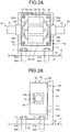
- FIG. 2A is a front view schematically illustrating the second module 32
- FIG. 2B is a schematic right-side view of the second module 32 illustrated in FIG. 2A
- the second module 32 may be described as “module 32”
- the second module-supporting portion 42 may be described as “module supporting portion 42”.
- the modules 32 there are a plurality of types of the modules 32, and the modules the number of which corresponds to the number of types of the cables 20 that can be coupled are prepared (see FIG. 4 described later).
- the module 32 corresponding to the determined type of the cable 20 is selected out of the modules 32 of different types and is attached on the module supporting portion 42.
- the cable 20 here, as illustrated in FIG. 2A , has a power cable 20a, an air hose 20b, and a cooling water hose 20c.
- the module 32 provided with a plurality (e.g., three pieces) of devices 51 to 53 and a housing portion 54 is selected according to the specification of the robot 1.
- the device 51 is referred to as "first device 51”
- the device 52 is referred to as “second device 52”
- the device 53 is referred to as "third device 53”.
- FIG. 2A to simplify the illustration, the first to the third devices 51 to 53 are schematically represented as blocks.
- the first device 51 is a device to which the power cable 20a is connected, and is a relay box for power supply, for example.
- the second device 52 is a device to which the air hose 20b is connected, and is a device for air, for example, a valve.
- the third device 53 is a device to which the cooling water hose 20c is connected, and is a device for cooling water, for example, a flow meter.
- the housing portion 54 is in a rectangular parallelepiped shape, and is formed to have a space 54a inside, for example.
- the first to the third devices 51 to 53 in the foregoing are fixed in a housed state.
- third device 53 is specifically defined as a flow meter, it is illustrative only, and depending on the specification of the robot 1, it may be a valve for cooling water. Furthermore, as indicated by imaginary lines in FIG. 2A , when the device for cooling water is not necessary in the portion of the module 32 according to the specification of the robot 1, it may be a coupling hose 55 that directly couples the cooling water hoses 20c. Likewise, the specific devices cited above for the first and the second devices 51 and 52 are illustrative only, and are to be changed according to the specification of the robot 1.
- a plurality of types of the cables 20 as well as a plurality of types of the modules 32 are prepared first.
- the cable 20 corresponding to the type of the end effector 3 is selected out of the cables 20 of different types and is arranged, and the module 32 corresponding to the type of the cable 20 is selected out of the modules 32 of different types and is attached. Consequently, the time taken from the determination of the specification of the robot 1 to the completion of the robot 1 can be reduced as much as possible, and the manufacturability of the robot 1 itself can be improved.
- the time taken to complete the robot 1 can be reduced compared to a situation in which the cables and devices are made after the specification is determined and the cables and others made are then arranged on the robot 1, for example.
- reducing the manufacturing time of the robot 1 can improve the manufacturability of the robot 1 itself.
- the second module 32 is explained as an example in the foregoing, the same applies to the first, the third, and the fourth modules 31, 33, and 34.
- a plurality of types of the first, the third, and the fourth modules 31, 33, and 34 are prepared, and the respective modules according to the specification of the robot 1, for example, the type of the cable 20, are selected and attached. This can yield the same effects such as the reduction in the manufacturing time of the robot 1 and the improvement in the manufacturability of the robot 1 itself.
- the devices to be mounted on the first module 31 are preferable to be a filter for air and a connecting adaptor for a cooling water hose, for example.
- a filter for air and a connecting adaptor for a cooling water hose, for example.
- they are not limited to these.
- the second and the third modules 32 and 33 are positioned at heights in the robot body 2 that are easy for an operator to perform operation or to see. For this reason, the devices to be mounted on the second and the third modules 32 and 33 are preferable to be a valve and a meter gauge that are operated or visibly checked by a worker, for example. However, they are not limited to these.
- the devices to be mounted thereon are preferable to be a relatively large device, for example, an information lamp that turns on when the power is applied to the power cable.
- a relatively large device for example, an information lamp that turns on when the power is applied to the power cable.
- they are not limited to this.
- the fourth module 34 is inserted immediately before the end effector 3 in the cable 20.
- the device to be mounted on the fourth module 34 is preferable to be, for example, a converter that converts the cables and hoses of the cable 20 into the connectors or the like in shapes suitable for connection to the end effector 3.
- a converter that converts the cables and hoses of the cable 20 into the connectors or the like in shapes suitable for connection to the end effector 3.
- it is not limited to this.
- the module 32 thus structured is, as illustrated in FIGS. 2A and 2B , connected to and supported by the module supporting portion 42 via an attaching member 60.
- the attaching member 60 includes a base portion 61 and a sidewall portion 62.
- the base portion 61 contacts the module supporting portion 42, and is formed in a flat plate shape.
- the sidewall portion 62 is formed to extend from the end portion of the base portion 61 in the direction perpendicular to the base portion 61. Consequently, the attaching member 60 is formed in a substantially L-shape in a side view, for example.
- the shape of the attaching member 60 is not limited to the foregoing, and may be in another shape such as a substantially U-shape and an inverted T-shape in a side view.
- Appropriate positions of the base portion 61 have insertion holes 61a through which respective bolts 71 can be inserted.
- insertion holes 61a In the module supporting portion 42, further formed at the positions corresponding to the insertion holes 61a are female screw portions 42a into which the bolts 71 can be fitted.
- appropriate positions of the housing portion 54 of the module 32 have insertion holes 54b through which respective bolts 72 can be inserted.
- insertion holes 54b In the sidewall portion 62, further formed at the positions corresponding to the insertion holes 54b are female screw portions 62a into which the bolts 72 can be fitted.
- the module 32 is connected to and supported by the module supporting portion 42 via the attaching member 60.
- the respective numbers and positions of the bolts 71 and 72, the insertion holes 61a and 54b, and the female screw portions 42a and 62a are not limited to those illustrated in the drawings.
- the devices to be mounted on the module 32 vary depending on the type of the cable 20, and thus the size of the housing portion 54 in the module 32 may also vary depending on the type of the cable 20.
- the positions of the insertion holes 54b of the housing portion 54 are changed so as to align with the female screw portions 62a. This enables the module 32 after the change to be attached to the attaching member 60 even when the type of the module 32 is changed.
- the attaching member 60 can be standardized, and thus the number of components to be prepared before manufacturing the robot 1 can be reduced.
- the module 32 is exemplified to include the housing portion 54 in the foregoing, such a structure is illustrative only, and by removing the housing portion 54, the first to the third devices 51 to 53 may be fixed directly onto the attaching member 60. Furthermore, by removing the attaching member 60, the first to the third devices 51 to 53 may be fixed directly onto the module supporting portion 42.
- the module 32 is not necessary to be fixed onto the module supporting portion 42, and the module 32 may be placed on and supported by the module supporting portion 42, for example.
- the foregoing description in which the housing portion 54 and the attaching member 60 may be removed and the module 32 may be placed on the module supporting portion 42 also applies to the first, the third, and the fourth modules 31, 33, and 34.
- FIG. 3 is a flowchart illustrating the manufacturing procedure of the robot 1.
- FIG. 4 is a diagram for explaining the outfitting of the robot 1. It is assumed that the robot body 2 and the end effector 3 have been prepared in advance.
- a plurality of types of the cables 20, that is, the cables 20 composed of a plurality of sub cables 21 to 27 are first prepared (arranged) in advance based on the types of the end effectors 3 that may be mounted on the robot 1. Furthermore, based on the types of the prepared cables 20, a plurality of types of the first to the fourth modules 31 to 34 each are also prepared (Step S1).
- FIG. 4 although a plurality of types of the cables 20 and those of the first to the fourth modules 31 to 34 are illustrated in the same shapes to simplify the illustration, the cables and hoses included therein or the devices mounted thereon are different from one another. Furthermore, in FIG. 4 , although the cable 20 is illustrated as a single cable to simplify the illustration, the cable 20 is assumed to be divided into the first to the seventh sub cables 21 to 27 as in the foregoing.
- the cable 20 is selected from the cables 20 of different types in accordance with the type of the end effector 3 (Step S2).
- the topmost cable 20 in the drawing was selected.
- the first to the fourth modules 31 to 34 are selected according to the type of the cable 20 to couple (Step S3).
- the topmost ones of the first to the fourth modules 31 to 34 in the drawing were selected.
- the cable 20 selected at Step S2 is arranged on the robot 1 (Step S4).
- the sub cables 21 to 27 are arranged along the robot body 2.
- the first to the fourth modules 31 to 34 selected at Step S3 are provided on the robot body 2 while being inserted between the divided cables 20, and then the cables 20 (the sub cables 21 to 27) are coupled together (Step S5).
- the first to the fourth modules 31 to 34 are supported by the respective first to the fourth module-supporting portions 41 to 44 (Step S5).
- Step S5 the connection of the fourth sub cable 24 and the fifth sub cable 25, and the connection of the fifth sub cable 25 and the sixth sub cable 26 are also made. Subsequently, connecting the end effector 3 to the cable 20 completes the robot 1.
- the robot 1 includes the robot body 2 and the end effector 3.
- the end effector 3 is connected to the robot body 2.
- the cable 20 that is connected to the end effector 3 and divided into a plurality of cables in the directions of axes is arranged along the robot body 2.
- the first to the fourth module-supporting portions 41 to 44 supporting the first to the fourth modules 31 to 34, which are inserted between the divided cables 20 and couple the cables 20 together, are further provided on the robot body 2.
- the robot 1 Furthermore, disposing the first module 31 on the base 10, the second module 32 on the revolving portion 11, the third module 33 on the upper arm 13, and the fourth module 34 on the wrist portion 14 enables the robot 1 to employ various specifications.
- structuring the robot 1 in the foregoing manner allows the types and positions of the devices mounted on the first to the fourth modules 31 to 34 to be prepared in many patterns, and thus, even when the specification varies extensively, the robot 1 can be appropriately customized and manufactured.
- FIG. 5 is a schematic general view of the robot 1 illustrating a modification of the robot 1 in the embodiment.
- the second module 32 and the third module 33 are removed.
- Directly connecting the connector 22b of the second sub cable 22 and the connector 23a of the third sub cable 23 couples the second sub cable 22 and the third sub cable 23 together. Furthermore, directly connecting the connector 23b of the third sub cable 23 and the connector 24a of the fourth sub cable 24 couples the third sub cable 23 and the fourth sub cable 24 together.
- the robot 1 may be structured not to include the second module 32 and the third module 33. While the second module 32 and the third module 33 are not included in the foregoing, it is not limited to this and any one of or two or more of the first to the fourth modules 31 to 34 may be removed, for example.
- the robot 1 has been exemplified with a six-axis robot in the foregoing embodiment, it is not limited to such a configuration, and a robot other than a six-axis robot, for example, a seven-axis robot and an eight-axis robot can be used.
Landscapes
- Engineering & Computer Science (AREA)
- Robotics (AREA)
- Mechanical Engineering (AREA)
- Manipulator (AREA)
Applications Claiming Priority (1)
| Application Number | Priority Date | Filing Date | Title |
|---|---|---|---|
| JP2013156047A JP5928416B2 (ja) | 2013-07-26 | 2013-07-26 | ロボットおよびロボットの製造方法 |
Publications (3)
| Publication Number | Publication Date |
|---|---|
| EP2829369A2 EP2829369A2 (en) | 2015-01-28 |
| EP2829369A3 EP2829369A3 (en) | 2016-04-27 |
| EP2829369B1 true EP2829369B1 (en) | 2019-02-27 |
Family
ID=51257295
Family Applications (1)
| Application Number | Title | Priority Date | Filing Date |
|---|---|---|---|
| EP14178133.6A Active EP2829369B1 (en) | 2013-07-26 | 2014-07-23 | Robot and manufacturing method of the same |
Country Status (4)
| Country | Link |
|---|---|
| US (1) | US9764483B2 (ja) |
| EP (1) | EP2829369B1 (ja) |
| JP (1) | JP5928416B2 (ja) |
| CN (1) | CN104339366B (ja) |
Families Citing this family (19)
| Publication number | Priority date | Publication date | Assignee | Title |
|---|---|---|---|---|
| WO2012098128A1 (de) * | 2011-01-18 | 2012-07-26 | Leoni Kabel Holding Gmbh | Vorrichtung zur automatisierten zuführung von verbindungselementen zu einer verarbeitungseinheit sowie zuführschlauch für die verbindungselemente |
| CN104339365B (zh) * | 2013-07-26 | 2017-04-12 | 株式会社安川电机 | 机器人及机器人的制造方法 |
| JP5928416B2 (ja) | 2013-07-26 | 2016-06-01 | 株式会社安川電機 | ロボットおよびロボットの製造方法 |
| JP2016068202A (ja) * | 2014-09-30 | 2016-05-09 | セイコーエプソン株式会社 | ロボット |
| JP6752796B2 (ja) | 2015-08-20 | 2020-09-09 | ソニー・オリンパスメディカルソリューションズ株式会社 | 医療用観察装置および医療用観察システム |
| JP2017170586A (ja) | 2016-03-25 | 2017-09-28 | セイコーエプソン株式会社 | エンドエフェクター、ロボット、およびロボット制御装置 |
| DE102016004788A1 (de) * | 2016-04-20 | 2017-10-26 | Kastanienbaum GmbH | Verfahren zur Herstellung eines Roboters und Vorrichtung zur Durchführung dieses Verfahrens |
| DE102016008112A1 (de) * | 2016-06-28 | 2017-12-28 | Eisele Pneumatics Gmbh & Co. Kg | Handhabungssystem |
| JP2018051708A (ja) * | 2016-09-30 | 2018-04-05 | セイコーエプソン株式会社 | 水平多関節型ロボット |
| JP6546216B2 (ja) | 2017-05-22 | 2019-07-17 | ファナック株式会社 | 産業用ロボット |
| JP2019098407A (ja) | 2017-11-28 | 2019-06-24 | ファナック株式会社 | ロボット |
| CN107932556A (zh) * | 2017-12-04 | 2018-04-20 | 埃夫特智能装备股份有限公司 | 一种工业机器人线缆布置结构 |
| JP6629826B2 (ja) | 2017-12-25 | 2020-01-15 | ファナック株式会社 | ロボットとその線条体処理構造 |
| JP6730352B2 (ja) * | 2018-03-20 | 2020-07-29 | ファナック株式会社 | ケーブルクランプおよびロボット |
| JP7024579B2 (ja) * | 2018-04-25 | 2022-02-24 | セイコーエプソン株式会社 | ロボット制御装置、ロボットシステムおよびロボット制御方法 |
| JP6806124B2 (ja) * | 2018-11-16 | 2021-01-06 | 株式会社安川電機 | ロボット |
| JP7451889B2 (ja) * | 2019-06-27 | 2024-03-19 | セイコーエプソン株式会社 | ロボット |
| JP7277319B2 (ja) * | 2019-09-10 | 2023-05-18 | ファナック株式会社 | ロボット |
| JP7388887B2 (ja) * | 2019-11-13 | 2023-11-29 | ファナック株式会社 | ロボットの線条体ユニットおよび線条体配線方法 |
Family Cites Families (70)
| Publication number | Priority date | Publication date | Assignee | Title |
|---|---|---|---|---|
| JPS5922628B2 (ja) | 1980-06-25 | 1984-05-28 | 満男 内藤 | スポット溶接用空冷ケ−ブル |
| US4518308A (en) * | 1982-03-01 | 1985-05-21 | Acrobe Technology Inc. | Manipulator apparatus |
| JPS59169687A (ja) | 1983-03-16 | 1984-09-25 | Nissan Motor Co Ltd | ポ−タブルスポツト溶接装置における配線・配管群の接続構造 |
| US4780047A (en) * | 1985-04-05 | 1988-10-25 | Martin Marietta Energy Systems, Inc. | Advanced servo manipulator |
| JPS62199380A (ja) * | 1986-02-26 | 1987-09-03 | 三菱電機株式会社 | 産業用ロボツト装置 |
| US5155423A (en) * | 1986-02-18 | 1992-10-13 | Robotics Research Corporation | Industrial robot with servo |
| US4973215A (en) * | 1986-02-18 | 1990-11-27 | Robotics Research Corporation | Industrial robot with servo |
| JPH01118882U (ja) * | 1988-02-08 | 1989-08-11 | ||
| US5046375A (en) * | 1988-04-21 | 1991-09-10 | Massachusetts Institute Of Technology | Compact cable transmission with cable differential |
| JPH02124694U (ja) | 1989-03-24 | 1990-10-15 | ||
| DE9103497U1 (ja) * | 1991-03-21 | 1991-06-20 | Kuka Schweissanlagen + Roboter Gmbh, 8900 Augsburg, De | |
| SE515130C2 (sv) * | 1995-02-24 | 2001-06-11 | Abb Ab | Robotutrustning |
| JP3145012B2 (ja) * | 1995-07-12 | 2001-03-12 | シーケーディ株式会社 | 消音器 |
| US5784542A (en) * | 1995-09-07 | 1998-07-21 | California Institute Of Technology | Decoupled six degree-of-freedom teleoperated robot system |
| JP3962961B2 (ja) * | 1997-09-03 | 2007-08-22 | 株式会社安川電機 | 塗装用ロボット装置 |
| DE19817605A1 (de) * | 1998-04-17 | 1999-10-21 | Kuka Roboter Gmbh | Roboter mit zumindestens teilweise außenseitig verlaufenden Kabeln |
| US6394998B1 (en) | 1999-01-22 | 2002-05-28 | Intuitive Surgical, Inc. | Surgical tools for use in minimally invasive telesurgical applications |
| US6431018B1 (en) | 1999-09-09 | 2002-08-13 | Fanuc Ltd. | Guide device for wiring member and/or piping member and robot with guide device |
| JP2002283275A (ja) | 2001-03-21 | 2002-10-03 | Fanuc Ltd | ロボットの手首構造 |
| DE10141407A1 (de) * | 2001-04-19 | 2002-10-31 | Ernst & Engbring Gmbh & Co Kg | Vorrichtung zum Halten eines Leitungsbündels bei einem Roboter |
| SE522933C2 (sv) * | 2001-08-02 | 2004-03-16 | Abb Ab | Industrirobot utrustad med ett löstagbart kablage |
| JP5184602B2 (ja) | 2001-10-22 | 2013-04-17 | 株式会社安川電機 | 多関節ロボット |
| JP4099628B2 (ja) * | 2001-10-29 | 2008-06-11 | 株式会社安川電機 | 産業用ロボット |
| JP3746244B2 (ja) | 2002-04-10 | 2006-02-15 | ファナック株式会社 | ロボットの手首における線条体の敷設構造 |
| JP2003305684A (ja) * | 2002-04-15 | 2003-10-28 | Fanuc Ltd | 相対回転機構における線条体敷設構造 |
| CA2651806C (en) * | 2002-10-23 | 2012-06-05 | Fanuc Robotics America, Inc. | Robotic apparatus for painting |
| JP3739756B2 (ja) * | 2003-03-31 | 2006-01-25 | ファナック株式会社 | 配線・配管処理装置 |
| SE0303539D0 (sv) * | 2003-12-22 | 2003-12-22 | Abb Ab | Anordning för en industrirobot |
| JP4091928B2 (ja) | 2004-03-31 | 2008-05-28 | 株式会社不二越 | 産業用ロボットのアーム装置 |
| JP2006102859A (ja) | 2004-10-04 | 2006-04-20 | Nachi Fujikoshi Corp | 産業用ロボットのアーム装置 |
| JP2006150496A (ja) | 2004-11-29 | 2006-06-15 | Fanuc Ltd | ロボットの線条体支持装置及び線条体支持装置を備えたロボット |
| JP3944208B2 (ja) | 2004-12-02 | 2007-07-11 | ファナック株式会社 | ロボットの線条体案内装置及び線条体案内装置を備えたロボット |
| JP4349320B2 (ja) * | 2005-05-12 | 2009-10-21 | パナソニック株式会社 | マニピュレータ型ロボット |
| US7971504B2 (en) | 2005-09-27 | 2011-07-05 | Kabushiki Kaisha Yaskawa Denki | Articulated manipulator |
| EP1905551B1 (en) | 2006-09-27 | 2010-02-24 | Abb Ab | Industrial robot with pressurized air supply in balancing device |
| JP2008136925A (ja) * | 2006-12-01 | 2008-06-19 | Kyowa:Kk | 温水洗浄機 |
| ATE496739T1 (de) * | 2006-12-27 | 2011-02-15 | Abb Ab | Industrieroboter mit rohrelement für einen kabelbaum |
| JP2008221357A (ja) * | 2007-03-09 | 2008-09-25 | Yaskawa Electric Corp | 多関節ロボット |
| JP2008229762A (ja) * | 2007-03-19 | 2008-10-02 | Fanuc Ltd | 線条体収容型アームを備えたロボット |
| JP5151513B2 (ja) | 2008-02-01 | 2013-02-27 | 株式会社安川電機 | 線条体案内機構を備えた産業用ロボット |
| JP5180621B2 (ja) | 2008-03-04 | 2013-04-10 | 本田技研工業株式会社 | 多関節ロボット |
| JP5353500B2 (ja) | 2009-07-08 | 2013-11-27 | 株式会社安川電機 | ロボット |
| CN201881385U (zh) * | 2010-02-11 | 2011-06-29 | Abb技术公司 | 连接装置、紧固设备和工业机器人 |
| JP5450223B2 (ja) * | 2010-04-14 | 2014-03-26 | 株式会社ダイヘン | 産業用ロボット |
| JP4837117B2 (ja) | 2010-04-14 | 2011-12-14 | ファナック株式会社 | ロボットアーム部の線条体配設機構 |
| JP4865882B2 (ja) | 2010-04-16 | 2012-02-01 | ファナック株式会社 | ロボット手首部の線条体配設機構 |
| JP5201186B2 (ja) * | 2010-09-16 | 2013-06-05 | 株式会社安川電機 | ロボット |
| JP5344315B2 (ja) | 2010-11-04 | 2013-11-20 | 株式会社安川電機 | ロボットの手首構造及びロボット |
| WO2012098128A1 (de) | 2011-01-18 | 2012-07-26 | Leoni Kabel Holding Gmbh | Vorrichtung zur automatisierten zuführung von verbindungselementen zu einer verarbeitungseinheit sowie zuführschlauch für die verbindungselemente |
| JP2013022715A (ja) * | 2011-07-25 | 2013-02-04 | Yamaha Motor Co Ltd | スカラロボット |
| CN103056877B (zh) * | 2011-10-21 | 2015-07-29 | 鸿富锦精密工业(深圳)有限公司 | 机械手 |
| JP5891018B2 (ja) * | 2011-11-29 | 2016-03-22 | 株式会社ダイヘン | 産業用ロボット及び産業用ロボットのケーブル部の配置方法 |
| WO2013041153A1 (en) | 2011-12-28 | 2013-03-28 | Abb Technology Ltd | Process turning disc with a cable guide |
| CN202462412U (zh) * | 2012-01-13 | 2012-10-03 | 湖北中烟工业有限责任公司 | 一种工业机械手吸盘夹具的线缆和气管的外置式对接套件 |
| US9278455B2 (en) | 2012-04-20 | 2016-03-08 | Mitsubishi Electric Corporation | Robot joint structure |
| SI2894003T1 (sl) | 2012-05-15 | 2017-04-26 | Comau S.P.A. | Glava za električno točkovno varjenje za več osni industrijski robot z ohišjem in nosilno konstrukcijo; Robot, ki to glavo vsebuje |
| DE102012208448A1 (de) * | 2012-05-21 | 2013-11-21 | Kuka Roboter Gmbh | Industrieroboter mit in einem Handgrundgehäuse sich erstreckenden Antrieben |
| JP5591894B2 (ja) * | 2012-09-26 | 2014-09-17 | ファナック株式会社 | ロボットの線条体取付装置 |
| JP5661718B2 (ja) | 2012-10-12 | 2015-01-28 | ファナック株式会社 | ロボットの線条体取付装置 |
| JP6008112B2 (ja) | 2012-10-23 | 2016-10-19 | セイコーエプソン株式会社 | 水平多関節ロボット |
| JP5568121B2 (ja) | 2012-11-12 | 2014-08-06 | ファナック株式会社 | 産業用ロボットの手首先端部における線条体案内装置および産業用ロボット |
| JP2014100743A (ja) | 2012-11-16 | 2014-06-05 | Fanuc Ltd | 多関節ロボットのケーブル処理構造 |
| JP5413524B1 (ja) | 2013-01-17 | 2014-02-12 | 株式会社安川電機 | ロボット |
| JP5698783B2 (ja) | 2013-03-29 | 2015-04-08 | ファナック株式会社 | 分線盤を備えたロボット |
| JP5715198B2 (ja) | 2013-07-05 | 2015-05-07 | ファナック株式会社 | ロボット用駆動ケーブルの処理構造体及びそれを具備するロボット装置 |
| CN104339365B (zh) | 2013-07-26 | 2017-04-12 | 株式会社安川电机 | 机器人及机器人的制造方法 |
| JP5928416B2 (ja) | 2013-07-26 | 2016-06-01 | 株式会社安川電機 | ロボットおよびロボットの製造方法 |
| JP5949693B2 (ja) | 2013-07-30 | 2016-07-13 | 株式会社安川電機 | ロボット |
| JP5884785B2 (ja) | 2013-07-30 | 2016-03-15 | 株式会社安川電機 | ロボット |
| US10050359B2 (en) * | 2013-10-31 | 2018-08-14 | Seiko Epson Corporation | Robot |
-
2013
- 2013-07-26 JP JP2013156047A patent/JP5928416B2/ja active Active
-
2014
- 2014-07-11 CN CN201410332521.7A patent/CN104339366B/zh active Active
- 2014-07-23 EP EP14178133.6A patent/EP2829369B1/en active Active
- 2014-07-24 US US14/340,494 patent/US9764483B2/en active Active
Non-Patent Citations (1)
| Title |
|---|
| None * |
Also Published As
| Publication number | Publication date |
|---|---|
| JP5928416B2 (ja) | 2016-06-01 |
| CN104339366B (zh) | 2017-07-07 |
| EP2829369A2 (en) | 2015-01-28 |
| US9764483B2 (en) | 2017-09-19 |
| JP2015024473A (ja) | 2015-02-05 |
| CN104339366A (zh) | 2015-02-11 |
| US20150027262A1 (en) | 2015-01-29 |
| EP2829369A3 (en) | 2016-04-27 |
Similar Documents
| Publication | Publication Date | Title |
|---|---|---|
| EP2829369B1 (en) | Robot and manufacturing method of the same | |
| CN108858135B (zh) | 机器人 | |
| US7971504B2 (en) | Articulated manipulator | |
| US9440363B2 (en) | Robot and manufacturing method of the same | |
| EP2213425B1 (en) | Vertical multi-joint robot | |
| EP2756930B1 (en) | Robot | |
| US10562196B2 (en) | Robot, control device, and robot system | |
| US20120111135A1 (en) | Robot wrist structure and robot | |
| US10099364B2 (en) | Robot | |
| ES2899891T3 (es) | Herramienta eléctrica inteligente convertible | |
| US11077549B2 (en) | Robot and robot system | |
| JP2016022571A (ja) | ロボットの関節機構およびロボット | |
| EP2821178A1 (en) | Robotic system | |
| WO2011003451A1 (en) | A robot arm system and a robot arm | |
| US20180161991A1 (en) | Robot, robot control device, and robot system | |
| CN105291089A (zh) | 机器人 | |
| CN104440942B (zh) | 机器人 | |
| JP6386218B2 (ja) | ロボット | |
| JP2017131969A (ja) | ロボット | |
| US11926048B2 (en) | Modular robotic linkages | |
| JPH07266281A (ja) | ロボットの交換装置 | |
| CN101142870B (zh) | 用于为基底装配电气零部件的自动装配机 | |
| JP6638878B2 (ja) | ロボット、ロボットシステム、ロボットのメンテナンス方法 | |
| CN215163141U (zh) | 一种夹持装置和加工设备 | |
| US20240165795A1 (en) | Actuator |
Legal Events
| Date | Code | Title | Description |
|---|---|---|---|
| 17P | Request for examination filed |
Effective date: 20140723 |
|
| AK | Designated contracting states |
Kind code of ref document: A2 Designated state(s): AL AT BE BG CH CY CZ DE DK EE ES FI FR GB GR HR HU IE IS IT LI LT LU LV MC MK MT NL NO PL PT RO RS SE SI SK SM TR |
|
| AX | Request for extension of the european patent |
Extension state: BA ME |
|
| PUAI | Public reference made under article 153(3) epc to a published international application that has entered the european phase |
Free format text: ORIGINAL CODE: 0009012 |
|
| REG | Reference to a national code |
Ref country code: DE Ref legal event code: R079 Ref document number: 602014041686 Country of ref document: DE Free format text: PREVIOUS MAIN CLASS: B25J0019020000 Ipc: B25J0019000000 |
|
| PUAL | Search report despatched |
Free format text: ORIGINAL CODE: 0009013 |
|
| AK | Designated contracting states |
Kind code of ref document: A3 Designated state(s): AL AT BE BG CH CY CZ DE DK EE ES FI FR GB GR HR HU IE IS IT LI LT LU LV MC MK MT NL NO PL PT RO RS SE SI SK SM TR |
|
| AX | Request for extension of the european patent |
Extension state: BA ME |
|
| RIC1 | Information provided on ipc code assigned before grant |
Ipc: B25J 19/00 20060101AFI20160324BHEP |
|
| R17P | Request for examination filed (corrected) |
Effective date: 20161017 |
|
| RBV | Designated contracting states (corrected) |
Designated state(s): AL AT BE BG CH CY CZ DE DK EE ES FI FR GB GR HR HU IE IS IT LI LT LU LV MC MK MT NL NO PL PT RO RS SE SI SK SM TR |
|
| STAA | Information on the status of an ep patent application or granted ep patent |
Free format text: STATUS: EXAMINATION IS IN PROGRESS |
|
| 17Q | First examination report despatched |
Effective date: 20170328 |
|
| GRAP | Despatch of communication of intention to grant a patent |
Free format text: ORIGINAL CODE: EPIDOSNIGR1 |
|
| STAA | Information on the status of an ep patent application or granted ep patent |
Free format text: STATUS: GRANT OF PATENT IS INTENDED |
|
| INTG | Intention to grant announced |
Effective date: 20181012 |
|
| GRAS | Grant fee paid |
Free format text: ORIGINAL CODE: EPIDOSNIGR3 |
|
| GRAA | (expected) grant |
Free format text: ORIGINAL CODE: 0009210 |
|
| STAA | Information on the status of an ep patent application or granted ep patent |
Free format text: STATUS: THE PATENT HAS BEEN GRANTED |
|
| AK | Designated contracting states |
Kind code of ref document: B1 Designated state(s): AL AT BE BG CH CY CZ DE DK EE ES FI FR GB GR HR HU IE IS IT LI LT LU LV MC MK MT NL NO PL PT RO RS SE SI SK SM TR |
|
| REG | Reference to a national code |
Ref country code: GB Ref legal event code: FG4D |
|
| REG | Reference to a national code |
Ref country code: CH Ref legal event code: EP |
|
| REG | Reference to a national code |
Ref country code: AT Ref legal event code: REF Ref document number: 1100662 Country of ref document: AT Kind code of ref document: T Effective date: 20190315 |
|
| REG | Reference to a national code |
Ref country code: IE Ref legal event code: FG4D |
|
| REG | Reference to a national code |
Ref country code: DE Ref legal event code: R096 Ref document number: 602014041686 Country of ref document: DE |
|
| REG | Reference to a national code |
Ref country code: NL Ref legal event code: MP Effective date: 20190227 |
|
| REG | Reference to a national code |
Ref country code: LT Ref legal event code: MG4D |
|
| PG25 | Lapsed in a contracting state [announced via postgrant information from national office to epo] |
Ref country code: PT Free format text: LAPSE BECAUSE OF FAILURE TO SUBMIT A TRANSLATION OF THE DESCRIPTION OR TO PAY THE FEE WITHIN THE PRESCRIBED TIME-LIMIT Effective date: 20190627 Ref country code: LT Free format text: LAPSE BECAUSE OF FAILURE TO SUBMIT A TRANSLATION OF THE DESCRIPTION OR TO PAY THE FEE WITHIN THE PRESCRIBED TIME-LIMIT Effective date: 20190227 Ref country code: NO Free format text: LAPSE BECAUSE OF FAILURE TO SUBMIT A TRANSLATION OF THE DESCRIPTION OR TO PAY THE FEE WITHIN THE PRESCRIBED TIME-LIMIT Effective date: 20190527 Ref country code: NL Free format text: LAPSE BECAUSE OF FAILURE TO SUBMIT A TRANSLATION OF THE DESCRIPTION OR TO PAY THE FEE WITHIN THE PRESCRIBED TIME-LIMIT Effective date: 20190227 Ref country code: SE Free format text: LAPSE BECAUSE OF FAILURE TO SUBMIT A TRANSLATION OF THE DESCRIPTION OR TO PAY THE FEE WITHIN THE PRESCRIBED TIME-LIMIT Effective date: 20190227 Ref country code: FI Free format text: LAPSE BECAUSE OF FAILURE TO SUBMIT A TRANSLATION OF THE DESCRIPTION OR TO PAY THE FEE WITHIN THE PRESCRIBED TIME-LIMIT Effective date: 20190227 |
|
| PG25 | Lapsed in a contracting state [announced via postgrant information from national office to epo] |
Ref country code: GR Free format text: LAPSE BECAUSE OF FAILURE TO SUBMIT A TRANSLATION OF THE DESCRIPTION OR TO PAY THE FEE WITHIN THE PRESCRIBED TIME-LIMIT Effective date: 20190528 Ref country code: RS Free format text: LAPSE BECAUSE OF FAILURE TO SUBMIT A TRANSLATION OF THE DESCRIPTION OR TO PAY THE FEE WITHIN THE PRESCRIBED TIME-LIMIT Effective date: 20190227 Ref country code: BG Free format text: LAPSE BECAUSE OF FAILURE TO SUBMIT A TRANSLATION OF THE DESCRIPTION OR TO PAY THE FEE WITHIN THE PRESCRIBED TIME-LIMIT Effective date: 20190527 Ref country code: IS Free format text: LAPSE BECAUSE OF FAILURE TO SUBMIT A TRANSLATION OF THE DESCRIPTION OR TO PAY THE FEE WITHIN THE PRESCRIBED TIME-LIMIT Effective date: 20190627 Ref country code: LV Free format text: LAPSE BECAUSE OF FAILURE TO SUBMIT A TRANSLATION OF THE DESCRIPTION OR TO PAY THE FEE WITHIN THE PRESCRIBED TIME-LIMIT Effective date: 20190227 Ref country code: HR Free format text: LAPSE BECAUSE OF FAILURE TO SUBMIT A TRANSLATION OF THE DESCRIPTION OR TO PAY THE FEE WITHIN THE PRESCRIBED TIME-LIMIT Effective date: 20190227 |
|
| REG | Reference to a national code |
Ref country code: AT Ref legal event code: MK05 Ref document number: 1100662 Country of ref document: AT Kind code of ref document: T Effective date: 20190227 |
|
| PG25 | Lapsed in a contracting state [announced via postgrant information from national office to epo] |
Ref country code: IT Free format text: LAPSE BECAUSE OF FAILURE TO SUBMIT A TRANSLATION OF THE DESCRIPTION OR TO PAY THE FEE WITHIN THE PRESCRIBED TIME-LIMIT Effective date: 20190227 Ref country code: AL Free format text: LAPSE BECAUSE OF FAILURE TO SUBMIT A TRANSLATION OF THE DESCRIPTION OR TO PAY THE FEE WITHIN THE PRESCRIBED TIME-LIMIT Effective date: 20190227 Ref country code: SK Free format text: LAPSE BECAUSE OF FAILURE TO SUBMIT A TRANSLATION OF THE DESCRIPTION OR TO PAY THE FEE WITHIN THE PRESCRIBED TIME-LIMIT Effective date: 20190227 Ref country code: ES Free format text: LAPSE BECAUSE OF FAILURE TO SUBMIT A TRANSLATION OF THE DESCRIPTION OR TO PAY THE FEE WITHIN THE PRESCRIBED TIME-LIMIT Effective date: 20190227 Ref country code: DK Free format text: LAPSE BECAUSE OF FAILURE TO SUBMIT A TRANSLATION OF THE DESCRIPTION OR TO PAY THE FEE WITHIN THE PRESCRIBED TIME-LIMIT Effective date: 20190227 Ref country code: CZ Free format text: LAPSE BECAUSE OF FAILURE TO SUBMIT A TRANSLATION OF THE DESCRIPTION OR TO PAY THE FEE WITHIN THE PRESCRIBED TIME-LIMIT Effective date: 20190227 Ref country code: EE Free format text: LAPSE BECAUSE OF FAILURE TO SUBMIT A TRANSLATION OF THE DESCRIPTION OR TO PAY THE FEE WITHIN THE PRESCRIBED TIME-LIMIT Effective date: 20190227 Ref country code: RO Free format text: LAPSE BECAUSE OF FAILURE TO SUBMIT A TRANSLATION OF THE DESCRIPTION OR TO PAY THE FEE WITHIN THE PRESCRIBED TIME-LIMIT Effective date: 20190227 |
|
| REG | Reference to a national code |
Ref country code: DE Ref legal event code: R097 Ref document number: 602014041686 Country of ref document: DE |
|
| PG25 | Lapsed in a contracting state [announced via postgrant information from national office to epo] |
Ref country code: SM Free format text: LAPSE BECAUSE OF FAILURE TO SUBMIT A TRANSLATION OF THE DESCRIPTION OR TO PAY THE FEE WITHIN THE PRESCRIBED TIME-LIMIT Effective date: 20190227 Ref country code: PL Free format text: LAPSE BECAUSE OF FAILURE TO SUBMIT A TRANSLATION OF THE DESCRIPTION OR TO PAY THE FEE WITHIN THE PRESCRIBED TIME-LIMIT Effective date: 20190227 |
|
| PG25 | Lapsed in a contracting state [announced via postgrant information from national office to epo] |
Ref country code: AT Free format text: LAPSE BECAUSE OF FAILURE TO SUBMIT A TRANSLATION OF THE DESCRIPTION OR TO PAY THE FEE WITHIN THE PRESCRIBED TIME-LIMIT Effective date: 20190227 |
|
| PLBE | No opposition filed within time limit |
Free format text: ORIGINAL CODE: 0009261 |
|
| STAA | Information on the status of an ep patent application or granted ep patent |
Free format text: STATUS: NO OPPOSITION FILED WITHIN TIME LIMIT |
|
| 26N | No opposition filed |
Effective date: 20191128 |
|
| PG25 | Lapsed in a contracting state [announced via postgrant information from national office to epo] |
Ref country code: MC Free format text: LAPSE BECAUSE OF FAILURE TO SUBMIT A TRANSLATION OF THE DESCRIPTION OR TO PAY THE FEE WITHIN THE PRESCRIBED TIME-LIMIT Effective date: 20190227 Ref country code: SI Free format text: LAPSE BECAUSE OF FAILURE TO SUBMIT A TRANSLATION OF THE DESCRIPTION OR TO PAY THE FEE WITHIN THE PRESCRIBED TIME-LIMIT Effective date: 20190227 |
|
| REG | Reference to a national code |
Ref country code: CH Ref legal event code: PL |
|
| GBPC | Gb: european patent ceased through non-payment of renewal fee |
Effective date: 20190723 |
|
| PG25 | Lapsed in a contracting state [announced via postgrant information from national office to epo] |
Ref country code: TR Free format text: LAPSE BECAUSE OF FAILURE TO SUBMIT A TRANSLATION OF THE DESCRIPTION OR TO PAY THE FEE WITHIN THE PRESCRIBED TIME-LIMIT Effective date: 20190227 |
|
| REG | Reference to a national code |
Ref country code: BE Ref legal event code: MM Effective date: 20190731 |
|
| PG25 | Lapsed in a contracting state [announced via postgrant information from national office to epo] |
Ref country code: GB Free format text: LAPSE BECAUSE OF NON-PAYMENT OF DUE FEES Effective date: 20190723 |
|
| PG25 | Lapsed in a contracting state [announced via postgrant information from national office to epo] |
Ref country code: LI Free format text: LAPSE BECAUSE OF NON-PAYMENT OF DUE FEES Effective date: 20190731 Ref country code: BE Free format text: LAPSE BECAUSE OF NON-PAYMENT OF DUE FEES Effective date: 20190731 Ref country code: LU Free format text: LAPSE BECAUSE OF NON-PAYMENT OF DUE FEES Effective date: 20190723 Ref country code: CH Free format text: LAPSE BECAUSE OF NON-PAYMENT OF DUE FEES Effective date: 20190731 |
|
| PG25 | Lapsed in a contracting state [announced via postgrant information from national office to epo] |
Ref country code: FR Free format text: LAPSE BECAUSE OF NON-PAYMENT OF DUE FEES Effective date: 20190731 |
|
| PG25 | Lapsed in a contracting state [announced via postgrant information from national office to epo] |
Ref country code: IE Free format text: LAPSE BECAUSE OF NON-PAYMENT OF DUE FEES Effective date: 20190723 |
|
| PG25 | Lapsed in a contracting state [announced via postgrant information from national office to epo] |
Ref country code: CY Free format text: LAPSE BECAUSE OF FAILURE TO SUBMIT A TRANSLATION OF THE DESCRIPTION OR TO PAY THE FEE WITHIN THE PRESCRIBED TIME-LIMIT Effective date: 20190227 |
|
| PG25 | Lapsed in a contracting state [announced via postgrant information from national office to epo] |
Ref country code: HU Free format text: LAPSE BECAUSE OF FAILURE TO SUBMIT A TRANSLATION OF THE DESCRIPTION OR TO PAY THE FEE WITHIN THE PRESCRIBED TIME-LIMIT; INVALID AB INITIO Effective date: 20140723 Ref country code: MT Free format text: LAPSE BECAUSE OF FAILURE TO SUBMIT A TRANSLATION OF THE DESCRIPTION OR TO PAY THE FEE WITHIN THE PRESCRIBED TIME-LIMIT Effective date: 20190227 |
|
| PG25 | Lapsed in a contracting state [announced via postgrant information from national office to epo] |
Ref country code: MK Free format text: LAPSE BECAUSE OF FAILURE TO SUBMIT A TRANSLATION OF THE DESCRIPTION OR TO PAY THE FEE WITHIN THE PRESCRIBED TIME-LIMIT Effective date: 20190227 |
|
| PGFP | Annual fee paid to national office [announced via postgrant information from national office to epo] |
Ref country code: DE Payment date: 20230531 Year of fee payment: 10 |