EP2348754A1 - Haut-parleur et dispositif électronique comprenant un haut-parleur - Google Patents
Haut-parleur et dispositif électronique comprenant un haut-parleur Download PDFInfo
- Publication number
- EP2348754A1 EP2348754A1 EP09827337A EP09827337A EP2348754A1 EP 2348754 A1 EP2348754 A1 EP 2348754A1 EP 09827337 A EP09827337 A EP 09827337A EP 09827337 A EP09827337 A EP 09827337A EP 2348754 A1 EP2348754 A1 EP 2348754A1
- Authority
- EP
- European Patent Office
- Prior art keywords
- diaphragm
- coupling cone
- loudspeaker
- damper
- elongated portions
- Prior art date
- Legal status (The legal status is an assumption and is not a legal conclusion. Google has not performed a legal analysis and makes no representation as to the accuracy of the status listed.)
- Granted
Links
- 230000008878 coupling Effects 0.000 claims abstract description 166
- 238000010168 coupling process Methods 0.000 claims abstract description 166
- 238000005859 coupling reaction Methods 0.000 claims abstract description 166
- 230000003014 reinforcing effect Effects 0.000 claims description 36
- 238000010586 diagram Methods 0.000 description 24
- 239000000463 material Substances 0.000 description 18
- 230000000694 effects Effects 0.000 description 11
- 238000000034 method Methods 0.000 description 6
- 238000004804 winding Methods 0.000 description 6
- 229920001721 polyimide Polymers 0.000 description 5
- 230000004044 response Effects 0.000 description 5
- 239000004642 Polyimide Substances 0.000 description 4
- 229910052782 aluminium Inorganic materials 0.000 description 4
- XAGFODPZIPBFFR-UHFFFAOYSA-N aluminium Chemical compound [Al] XAGFODPZIPBFFR-UHFFFAOYSA-N 0.000 description 4
- 239000011888 foil Substances 0.000 description 4
- 238000004458 analytical method Methods 0.000 description 3
- 239000004744 fabric Substances 0.000 description 3
- 230000004907 flux Effects 0.000 description 3
- 230000001976 improved effect Effects 0.000 description 3
- 230000002093 peripheral effect Effects 0.000 description 3
- 230000035699 permeability Effects 0.000 description 3
- 229920006254 polymer film Polymers 0.000 description 3
- 238000003825 pressing Methods 0.000 description 3
- KXGFMDJXCMQABM-UHFFFAOYSA-N 2-methoxy-6-methylphenol Chemical compound [CH]OC1=CC=CC([CH])=C1O KXGFMDJXCMQABM-UHFFFAOYSA-N 0.000 description 2
- RTAQQCXQSZGOHL-UHFFFAOYSA-N Titanium Chemical compound [Ti] RTAQQCXQSZGOHL-UHFFFAOYSA-N 0.000 description 2
- 239000000853 adhesive Substances 0.000 description 2
- 230000001070 adhesive effect Effects 0.000 description 2
- 239000000428 dust Substances 0.000 description 2
- 229920001971 elastomer Polymers 0.000 description 2
- 238000013007 heat curing Methods 0.000 description 2
- 239000004973 liquid crystal related substance Substances 0.000 description 2
- 238000005259 measurement Methods 0.000 description 2
- 229910052751 metal Inorganic materials 0.000 description 2
- 239000002184 metal Substances 0.000 description 2
- 238000000465 moulding Methods 0.000 description 2
- 229920001568 phenolic resin Polymers 0.000 description 2
- 239000005011 phenolic resin Substances 0.000 description 2
- 230000008569 process Effects 0.000 description 2
- 230000009467 reduction Effects 0.000 description 2
- 238000005096 rolling process Methods 0.000 description 2
- 230000001629 suppression Effects 0.000 description 2
- 239000010936 titanium Substances 0.000 description 2
- 229910052719 titanium Inorganic materials 0.000 description 2
- 239000004925 Acrylic resin Substances 0.000 description 1
- 229920000178 Acrylic resin Polymers 0.000 description 1
- RYGMFSIKBFXOCR-UHFFFAOYSA-N Copper Chemical compound [Cu] RYGMFSIKBFXOCR-UHFFFAOYSA-N 0.000 description 1
- 239000004640 Melamine resin Substances 0.000 description 1
- 229920000877 Melamine resin Polymers 0.000 description 1
- 230000002159 abnormal effect Effects 0.000 description 1
- 238000005452 bending Methods 0.000 description 1
- 230000005540 biological transmission Effects 0.000 description 1
- 230000008859 change Effects 0.000 description 1
- 239000004020 conductor Substances 0.000 description 1
- 229910052802 copper Inorganic materials 0.000 description 1
- 239000010949 copper Substances 0.000 description 1
- 230000006866 deterioration Effects 0.000 description 1
- 239000000806 elastomer Substances 0.000 description 1
- 230000005484 gravity Effects 0.000 description 1
- 230000002452 interceptive effect Effects 0.000 description 1
- 238000004519 manufacturing process Methods 0.000 description 1
- 239000009719 polyimide resin Substances 0.000 description 1
- 238000012795 verification Methods 0.000 description 1
- 230000003313 weakening effect Effects 0.000 description 1
Images


Classifications
-
- H—ELECTRICITY
- H04—ELECTRIC COMMUNICATION TECHNIQUE
- H04R—LOUDSPEAKERS, MICROPHONES, GRAMOPHONE PICK-UPS OR LIKE ACOUSTIC ELECTROMECHANICAL TRANSDUCERS; DEAF-AID SETS; PUBLIC ADDRESS SYSTEMS
- H04R9/00—Transducers of moving-coil, moving-strip, or moving-wire type
- H04R9/02—Details
- H04R9/04—Construction, mounting, or centering of coil
-
- H—ELECTRICITY
- H04—ELECTRIC COMMUNICATION TECHNIQUE
- H04R—LOUDSPEAKERS, MICROPHONES, GRAMOPHONE PICK-UPS OR LIKE ACOUSTIC ELECTROMECHANICAL TRANSDUCERS; DEAF-AID SETS; PUBLIC ADDRESS SYSTEMS
- H04R7/00—Diaphragms for electromechanical transducers; Cones
- H04R7/02—Diaphragms for electromechanical transducers; Cones characterised by the construction
- H04R7/04—Plane diaphragms
-
- H—ELECTRICITY
- H04—ELECTRIC COMMUNICATION TECHNIQUE
- H04R—LOUDSPEAKERS, MICROPHONES, GRAMOPHONE PICK-UPS OR LIKE ACOUSTIC ELECTROMECHANICAL TRANSDUCERS; DEAF-AID SETS; PUBLIC ADDRESS SYSTEMS
- H04R9/00—Transducers of moving-coil, moving-strip, or moving-wire type
- H04R9/06—Loudspeakers
-
- H—ELECTRICITY
- H04—ELECTRIC COMMUNICATION TECHNIQUE
- H04R—LOUDSPEAKERS, MICROPHONES, GRAMOPHONE PICK-UPS OR LIKE ACOUSTIC ELECTROMECHANICAL TRANSDUCERS; DEAF-AID SETS; PUBLIC ADDRESS SYSTEMS
- H04R2307/00—Details of diaphragms or cones for electromechanical transducers, their suspension or their manufacture covered by H04R7/00 or H04R31/003, not provided for in any of its subgroups
- H04R2307/021—Diaphragms comprising cellulose-like materials, e.g. wood, paper, linen
-
- H—ELECTRICITY
- H04—ELECTRIC COMMUNICATION TECHNIQUE
- H04R—LOUDSPEAKERS, MICROPHONES, GRAMOPHONE PICK-UPS OR LIKE ACOUSTIC ELECTROMECHANICAL TRANSDUCERS; DEAF-AID SETS; PUBLIC ADDRESS SYSTEMS
- H04R2307/00—Details of diaphragms or cones for electromechanical transducers, their suspension or their manufacture covered by H04R7/00 or H04R31/003, not provided for in any of its subgroups
- H04R2307/025—Diaphragms comprising polymeric materials
-
- H—ELECTRICITY
- H04—ELECTRIC COMMUNICATION TECHNIQUE
- H04R—LOUDSPEAKERS, MICROPHONES, GRAMOPHONE PICK-UPS OR LIKE ACOUSTIC ELECTROMECHANICAL TRANSDUCERS; DEAF-AID SETS; PUBLIC ADDRESS SYSTEMS
- H04R2307/00—Details of diaphragms or cones for electromechanical transducers, their suspension or their manufacture covered by H04R7/00 or H04R31/003, not provided for in any of its subgroups
- H04R2307/027—Diaphragms comprising metallic materials
Definitions
- the present invention relates to a loudspeaker, and in particular, relates to a technique of reducing a loudspeaker in width and thickness.
- a television loudspeaker unit is usually attached to both sides of an image display device so as to output stereo sound with improved effect, which contributes to the increase in width of the entire television set.
- loudspeakers commonly included in a television loudspeaker unit are of elongated shapes (hereinafter referred to as a "narrow loudspeaker”) such as rectangular or elliptical.
- a narrow loudspeaker elongated shapes
- demand is strong for even narrower loudspeakers because of the increase in width of image display devices, while demand is also strong for narrow loudspeakers having high sound quality that are capable of reproducing dynamic sound commensurate with the dynamism of the large screens.
- image display devices have also been being reduced in thickness, and therefore there is also a demand for the reduction in thickness of narrow loudspeakers.
- FIG. 26(a) through (c) is a diagram showing the structure of a conventional narrow loudspeaker.
- FIG. 26(a) is a plan view;
- FIG. 26(b) is a cross-sectional view taken in the longitudinal direction (c - c'); and
- FIG. 26(c) is a cross-sectional view taken in the transverse direction (o - o').
- 26(a) through (c) includes a magnet 101, a plate 102, a center pole 103, a frame 104, a voice coil bobbin 105, a voice coil 106, a damper 107, a diaphragm 109, a dust cap 110, and an edge 111. Further, magnetic gaps 108 are formed with the magnet 101, the plate 102, and the center pole 103.
- the voice coil 106 is a winding formed of a conductor such as copper or aluminum, and is fixed to the cylindrical voice coil bobbin 105.
- the voice coil bobbin 105 supports the voice coil 106 so as to suspend the voice coil 106 within the magnetic gaps 108.
- the voice coil bobbin 105 is connected to the frame 104 through the damper 107.
- the voice coil bobbin 105 is adhered to the diaphragm 109 on the opposite side of the voice coil bobbin 105 to that on which the voice coil 106 is fixed to the voice coil bobbin 105, the diaphragm 109 being of an elliptical or generally elliptical shape.
- the dust cap 110 is fixed to the central portion of the diaphragm 109, and has a cross section of a generally semicircular shape.
- the edge 111 is of a loop shape and has a cross section of a semicircular shape, and the inner peripheral portion of the edge 111 is fixed to the outer peripheral portion of the diaphragm 109.
- the outer peripheral portion of the edge 111 is fixed to the frame 104.
- Patent Literature 1 discloses a loudspeaker having a similar structure to that of the narrow loudspeaker 100.
- FIG. 27 is a diagram showing the frequency characteristics of the reproduction sound pressure level of the conventional narrow loudspeaker disclosed in Patent Literature 1.
- the vertical axis represents the reproduction sound pressure level obtained at the point 1 m away from the loudspeaker on an axis extending forward therefrom when 1 W is input thereto, and the horizontal axis represents the driving frequency.
- the conventional narrow loudspeaker as described above has the following problems.
- the narrow loudspeaker 100 shown in FIG. 26 employs a method of driving the central portion of the elongated diaphragm 109, and therefore is likely to cause break-up resonances in the longitudinal direction.
- the frequency characteristics of the reproduction sound pressure level have peaks and dips in the mid-range and high range, which causes the deterioration of sound quality.
- noticeable dips are observed at around 2 kHz, 3 kHz, and 5 kHz.
- the diaphragm 109 of the narrow loudspeaker 100 is of a deep shape, so as to improve rigidity because of resonances likely to occur in the longitudinal direction.
- the damper 107 is fixed to the middle of the voice coil bobbin 105, and space is provided between the voice coil bobbin 105 and a magnetic circuit, as a buffer for vibration-range-related collision.
- the diaphragm 109, the upper portion of the voice coil bobbin 105, the damper 107, the lower portion of the voice coil bobbin 105, and the magnetic circuit are placed in this order in series in the vibration direction, and therefore the depth of the loudspeaker is the total height of the components placed in series. This makes it difficult to reduce the entire height of the loudspeaker.
- the loudspeaker according to the present invention is a loudspeaker, elongated as viewed from a direction in which sound waves are emitted therefrom, the loudspeaker including: an elongated flat-plate-shaped diaphragm; a frame having an opening portion larger than the diaphragm; an edge placed between an inner periphery of the frame around the opening portion and an outer periphery of the diaphragm and supporting and allowing the diaphragm to easily vibrate in the emission direction of sound waves, with the diaphragm orthogonal to the emission direction; a coupling cone extending from a rear surface of the diaphragm, as viewed from the emission direction of sound waves, and including two elongated portions arranged parallel to a longitudinal direction of the diaphragm, the coupling cone vibrating in conjunction with the diaphragm; a voice coil wound around at least the two elongated portions of the
- the coupling cone preferably has an air-permeable structure.
- a longitudinal length of the coupling cone is preferably 60% or more of a longitudinal length of the diaphragm.
- the root positions of the two elongated portions of the coupling cone are preferably substantially the same as positions of respective nodes of a first resonant mode in a transverse direction of the diaphragm.
- the coupling cone preferably has reinforcing ribs in the two elongated portions, the reinforcing ribs forming projections and depressions parallel to the longitudinal direction of the diaphragm.
- the diaphragm preferably has reinforcing ribs between the two elongated portions of the coupling cone extending from the rear surface of the diaphragm, the reinforcing ribs forming projections and depressions parallel to the longitudinal direction of the diaphragm.
- the magnetic circuit preferably comprises a plurality of magnetic circuits arranged in the longitudinal direction of the diaphragm, and the loudspeaker preferably further includes a damper between each adjacent pair of the magnetic circuits, the damper being connected to part of the end positions of the two elongated portions of the coupling cone and supporting and allowing the coupling cone to easily vibrate in the emission direction of sound waves.
- the damper preferably has rolls extending parallel to the longitudinal direction of the diaphragm.
- the loudspeaker preferably further includes dampers on far end sides of the magnetic circuits arranged at both ends.
- the part connected to the coupling cone is preferably of a truncated pyramidal shape.
- the connecting part between the damper and the coupling cone preferably forms a prismatic structure based on a combination of the damper and the coupling cone.
- the part connected to the damper is preferably integrally molded with part of a reinforcing member to form the prismatic structure when connected.
- the present invention is directed to an electronic device, such as a television or an automobile, having incorporated therein the loudspeaker.
- the electronic device according to the present invention is an electronic device having mounted therein a loudspeaker elongated as viewed from a direction in which sound waves are emitted therefrom, and the electronic device has mounted therein the loudspeaker.
- the present invention even when the central portion of a diaphragm of a narrow loudspeaker is not shaped into a dome, it is possible to suppress the occurrence of break-up resonances in the diaphragm, realize high sound quality by extending the limiting high frequency of the loudspeaker, and reduce the loudspeaker in width and thickness.
- the present invention with the provision of two elongated portions arranged in the longitudinal direction in a coupling cone, it is possible to suppress resonances in the longitudinal direction of the diaphragm.
- the loudspeaker according to the present invention is capable of vibrating greatly for its size and thickness, and excels in bass reproduction.
- an electronic device such as a television, a mobile phone, or an automobile, that has mounted therein the loudspeaker as described above is capable of reproducing high-quality sound without significantly increasing the width and thickness thereof.
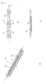
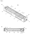
- FIG. 1(a) is a perspective view of the appearance of a loudspeaker 10 according to a first embodiment.
- FIG. 1(b) is a cross-sectional view (a cross section A-A') taken in the longitudinal direction, and at an approximate center, of the loudspeaker.
- FIG. 1(c) is a cross-sectional view (a cross section B-B') taken in the transverse direction, and at an approximate center, of the loudspeaker.
- the loudspeaker 10 shown in FIG. 1(a) through (c) is a narrow loudspeaker of an elongated shape, whose longitudinal and transverse lengths differ from each other when viewed from the front direction (as viewed from above, in FIG. 1(b) and (c) ) in which sound waves are mainly emitted.
- the loudspeaker 10 includes a diaphragm 11, an edge 12, a frame 13, a voice coil 14, a coupling cone 15, magnets 16, a center pole 17, and top plates 18.
- the diaphragm 11 is of a generally flat shape, and of a race-track-like elongated shape whose outlines on the long sides are straight lines and whose outlines on the short sides are arcs.
- the edge 12 surrounds the outer periphery of the diaphragm 11 in a loop manner, and has a cross section of a generally semicircular shape (see FIG. 1(c) ).
- the frame 13 is of a loop shape having a large opening portion particularly on the front face thereof.
- the outer periphery of the diaphragm 11 is fixed to the inner periphery of the edge 12.
- the outer periphery of the edge 12 is fixed to the frame 13 around the opening portion of the frame 13.
- the diaphragm 11 only needs to be of an elongated shape, and does not necessarily need to be of a race-track-like elliptical shape.
- the outlines on the short sides of the diaphragm 11 may not be arcs and may be other curves. Further, the outlines on the short sides of the diaphragm 11 do not necessarily need to be curves.
- the diaphragm 11 may be, for example, of an elongated rectangular shape.
- the materials of the diaphragm 11 and the edge 12 paper; lightweight, high rigidity metal foil formed of, for example, aluminum or titanium; polymer film formed of, for example, polyimide; or the like.
- the diaphragm 11 and the edge 12 may be formed of different materials, or may be formed of the same material. Alternatively, the diaphragm 11 and the edge 12 may be integrally molded of the same material.
- the two magnets 16, the center pole 17, and the two top plates 18 form an open-type magnetic circuit and are fixed to the frame 13, so as to generate magnetic flux in magnetic gaps ("G" in FIG. 1(c) ) and provide the voice coil 14, placed within the magnetic gaps, with driving force for generating sound waves.
- the magnets 16, the center pole 17, and the top plates 18 are of elongated shapes when viewed from the front direction.
- the magnets 16, the center pole 17, and the top plates 18 are placed such that the longitudinal direction of each coincides with the longitudinal direction of the diaphragm 11.
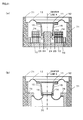
- Transverse cross sections of the magnets 16 are of rectangular shapes when viewed along the longitudinal direction, and with reference to this cross section, the magnets 16 are fixed to the two bottom surfaces, respectively, that are formed by the frame 13 and the center pole 17.
- a transverse cross section of the center pole 17 is of a T-shape when viewed along the longitudinal direction, and assumes an upside-down T-shape when the diaphragm 11 is faced up as shown in FIG. 1(c) .
- the center pole 17 has two side surfaces adjacent to the two respective bottom surfaces and extending in the longitudinal direction.
- Transverse cross sections of the top plates 18 are of rectangular shapes when viewed along the longitudinal direction, and the top plates 18 are fixed to the top surfaces of the respective magnets 16.
- the two side surfaces of the center pole 17 are each placed so as to oppose one longitudinal surface of the corresponding magnet 16 and one longitudinal surface of the corresponding top plate 18, with constant spaces maintained therebetween. These spaces serve as the magnetic gaps ("G" in FIG. 1(c) ).
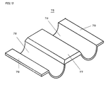
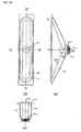
- FIG. 2 is a perspective view of the appearance of the coupling cone 15.
- the outline shape of the coupling cone 15 is equivalent to that of the diaphragm 11, or is an elongated shape of a smaller size of the diaphragm 11.
- the coupling cone 15 has the structure where the coupling cone 15 is fixed to the rear surface, of the diaphragm 11, as viewed from the emission direction of sound waves, and extends from the rear surface, such that center lines X of the coupling cone 15 and the diaphragm 11 coincide with each other.
- the longitudinal directions of the coupling cone 15 and the diaphragm 11 are generally parallel to each other, and the coupling cone 15 vibrates in conjunction with the diaphragm 11.
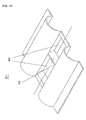
- FIG. 3 is a cross-sectional view of the coupling cone 15 taken in a transverse direction B-B' shown in FIG. 2 .
- flanges 20 serve as flaps provided so as to increase the area of adhesion between the coupling cone 15 and the diaphragm 11 to thereby improve the adhesiveness therebetween.
- the two portions extending from root positions 21 (the upper ends, in FIG. 3 ) to end positions 22 (the lower ends, in FIG.
- a transverse cross section of the coupling cone 15 is of an inverted trapezoidal shape, except for the flanges 20.
- fitting sections 23 are provided, into which the voice coil 14 is inserted so as to be fixed thereto. The voice coil 14 is fixed to the fitting sections 23.
- the following are suitable for the material of the coupling cone 15: paper; lightweight, high rigidity metal foil formed of, for example, aluminum or titanium; polymer film formed of, for example, polyimide; or the like.
- the coupling cone 15 may be formed of a different material from, or the same material as, those of the diaphragm 11 and the edge 12.
- the diaphragm 11 and the coupling cone 15 may be integrally molded of the same material, or the diaphragm 11, the edge 12, and the coupling cone 15 may be integrally molded of the same material.
- the voice coil 14 is placed within the magnetic gaps G.
- the two elongated portions of the coupling cone 15 are of such shapes and sizes that the entire two elongated portions, extending from the root positions 21 to the end positions 22, are included within the magnetic gaps G, respectively, when the coupling cone 15 vibrates in conjunction with the diaphragm 11.
- the end positions 22 of the coupling cone 15 are further from the center line X than side surfaces 24 (see FIG. 1(c) ), on the respective magnetic gap G sides, of the center pole 17 are.
- the root positions 21 of the coupling cone 15 are closer to the center line X than side surfaces 25 (see FIG. 1(c) ), on the magnetic gap G sides, of the respective magnets 16 and top plates 18 are.
- the coupling cone 15 is fixed to the diaphragm 11.
- the coupling cone 15 is fixed to the diaphragm 11 almost throughout the entire diaphragm 11 except for the end portions thereof.
- the longitudinal length of the coupling cone 15 is 60% or more of that of the diaphragm 11. That is, the coupling cone 15 is fixed to the diaphragm 11 at a portion corresponding to 60% or more thereof in the longitudinal direction.
- the coupling cone 15 is fixed to the diaphragm 11 at the positions of the nodes of a first resonant mode in the transverse direction of the diaphragm 11. That is, the root positions 21, at which the long sides of the coupling cone 15 are fixed to the diaphragm 11, are substantially the same as the positions of the respective nodes of the first resonant mode in the transverse direction of the diaphragm 11.
- the positions of the nodes of the first resonant mode in the transverse direction of the diaphragm 11 are the positions corresponding to 0.224 and 0.776, measured from the respective ends of the short side of the diaphragm 11, the length of the short side of the diaphragm 11 being 1. Note that here, only modes having an even number of nodal lines that contribute to sound pressure characteristics are taken into account, and the order of the modes is represented as first, second, third...
- the coupling cone 15 is of a shape that becomes wider upward from the voice coil 14 to the diaphragm 11, and therefore the transverse length of the voice coil 14 is slightly smaller than the distance between the nodes of the first resonant mode in the transverse direction of the diaphragm 11.
- optimal positions in the transverse direction at which the coupling cone 15 is attached to the diaphragm 11 is normally in the range from 0.2 to 0.25 and in the range from 0.75 to 0.8, in the transverse direction of the diaphragm 11.
- the diaphragm 11 is driven in a portion corresponding to 60% or more thereof, which is approximately equal to the entire driving of the diaphragm 11.
- the diaphragm 11 is driven only at the positions of the nodes of the first resonant mode in the transverse direction of the diaphragm 11.
- the following is a description of the longitudinal and transverse resonances of a simple flat diaphragm.
- the aspect ratio of the diaphragm is 2:1 or more.
- a resonant frequency is in inverse proportion to the square of the length, and therefore the resonant frequency of a resonance generated in the transverse direction is calculated to be more than four times the resonant frequency of a resonance generated in the longitudinal direction.
- the diaphragm is driven at the positions of the nodes of the first resonant mode in the transverse direction, and thereby the first resonant mode is suppressed and the reproduction bandwidth is extended to a second resonant mode that follows.
- the second resonant frequency in the transverse direction is four to five times the first resonant frequency in the transverse direction, and therefore the reproduction bandwidth is extended to a very high frequency.
- the reproduction bandwidth is extended to a high frequency that is 16 times a first resonant frequency in the longitudinal direction or more.
- an edge is provided in the periphery of the flat diaphragm, and therefore a transverse resonant frequency is two to four times a longitudinal resonant frequency. Even in this case, the reproduction bandwidth is extended to 8 to up to 16 times the longitudinal resonant frequency.
- the coupling cone 15 serves to transmit driving force to the diaphragm 11, and also to prevent the diaphragm 11 and the open-type magnetic circuit from interfering with each other.
- the diaphragm 11 generates a wide vibration range in the bass range. For example, in order to reproduce a sound pressure of 88 dB/m at 100 Hz using a loudspeaker having a nominal diameter of 8 cm, a vibration range of 4 mm (from zero to peak) or more is required. Thus it is necessary to provide a distance of 4 mm or more between the rear surface of the diaphragm 11 and the top surface of the center pole 17.
- the voice coil 14 needs to be placed within the magnetic gaps G, and therefore the coupling cone 15 is required so as to connect the diaphragm 11 and the voice coil 14 and certainly transmit driving force to the diaphragm 11.
- the voice coil 14 is fitted to the vicinities of the end positions 22 of the coupling cone 15.
- a transverse cross section of the coupling cone 15 is basically of an inverted trapezoidal shape that becomes wider from the lower end side to the upper end side.
- the inverted trapezoidal shape in cross section of the coupling cone considerably improves the strength against lateral shift thereof as compared to a coupling cone of a simple rectangular parallelepiped shape. Consequently, it is possible to suppress the lateral (the direction orthogonal to the proper vibration direction) vibrations of the voice coil.
- a loudspeaker is produced using a cylindrical voice coil bobbin.
- the very elongated rectangular voice coil 14 according to the present embodiment (assuming that a rectangular voice coil of, for example, 100 mm x 8 mm is used so as to correspond to the shape of the loudspeaker according to the present embodiment), as in a conventional loudspeaker.
- the voice coil used in a conventional loudspeaker is formed by bringing a voice coil bobbin into firm contact with a cylindrical winding jig, pressing a voice coil wire on the bobbin while applying pressure thereto, and adhering the wire to the bobbin.
- a voice coil wire when a voice coil wire is wound around the bobbin, it is possible to perform the winding process while evenly applying pressure to the bobbin.
- a voice coil In the case of using a rectangular bobbin, however, a voice coil has long flat portions in the longitudinal direction, and therefore all the pressure applied to the flat portions when the winding is performed can be received only at both ends on the long side. Thus it is impossible to apply pressure inwardly against straight portions. This may impair the firm contact between the voice coil bobbin and the voice coil, and the voice coil may disengage.
- space may be produced between the bobbin and the coil underneath, or the ends, on the opposite sides to the winding sides, of the voice coil bobbin may undulate and deform.
- the windings of the voice coil 14 are independently formed into rectangular shape in advance, and fitted and adhered to the fitting sections 23 of the coupling cone 15 formed into a desired shape in advance.
- This process makes it possible that based on each component formed into the corresponding shape in advance, the coil is adhered to the fitting sections 23 in accordance therewith to thereby be firmly fixed thereto.
- the coupling cone 15 has the structure where the coupling cone 15 becomes wider from the lower end side (the end positions 22) to the upper end side (the root positions 21), and therefore can be formed by pressure-molding polyimide, thin aluminum foil, or the like. Thus it is relatively easy to provide a highly accurate coupling cone.
- the total height of the loudspeaker is the sum of: a distance D1 of the diaphragm vibrating in a maximum vibration range in the front surface direction; a distance D2 (approximately equal to the distance between the rear surface of the diaphragm and the top surface of the center pole) of the diaphragm vibrating in the maximum vibration range in the rear surface direction; a distance D3 (approximately equal to the distance between the end positions 22 of the coupling cone 15 and the upper end of the center pole 17) of the voice coil 14 vibrating in the maximum vibration range; a distance D4 between the upper end of the center pole 17 and the lower end of the voice coil 14; and a thickness D5 of the lower end portion of the center pole 17.
- a height Dc of the cone is required for ensuring rigidity.
- a damper is provided between an open-type magnetic circuit and the cone paper, the following are also required: a distance Dc between the lower end of the cone paper and the damper; and a maximum vibration range Dm between the damper and the open-type magnetic circuit at the bottom, so that the damper does not contact the open-type magnetic circuit.
- none of these features is required, and therefore it is possible to reduce the height of a loudspeaker to thereby provide a thin loudspeaker.
- a diaphragm 30 is used instead of the diaphragm 11 according to the first embodiment, the diaphragm 30 having a fitting groove.
- FIG. 4 is a perspective view of the appearance of the diaphragm 11 according to the first embodiment and the edge 12.
- FIG. 5(a) is a perspective view of the appearance of the diaphragm 30 according to the first variation and the edge 12.
- FIG. 5(b) is a cross-sectional view (a cross section B-B') taken in the transverse direction of the diaphragm 30 and the edge 12.
- the diaphragm 11 has a simple flat structure as shown in FIG. 4 .
- FIG. 4 is a perspective view of the appearance of the diaphragm 11 according to the first embodiment and the edge 12.
- FIG. 5(b) is a cross-sectional view (a cross section B-B') taken in the transverse direction of the diaphragm 30 and the edge 12.
- the diaphragm 11 has a simple flat
- the diaphragm 30 has the structure where a fitting groove 31 is provided in the diaphragm 11 according to the first embodiment so as to improve the adhesiveness between the diaphragm and the coupling cone 17. This makes it possible to provide a highly durable loudspeaker.
- FIG. 6(a) is a perspective view of the appearance of the diaphragm 40 according to the second variation and the edge 12.
- FIG. 6(b) is a diagram showing the diaphragm 40 and the edge 12, as viewed from the front direction (as viewed from above, in FIG. 6(a) ) in which sound waves are mainly emitted.
- FIG. 6(c) is a cross-sectional view (a cross section A-A') taken in the longitudinal direction of the diaphragm 40 and the edge 12. As shown in FIG.
- the diaphragm 40 has the structure where reinforcing ribs 41 are provided in the diaphragm 11 according to the first embodiment at the portion to which the coupling cone 17 is connected and which is between the root positions 21, the reinforcing ribs 41 forming projections and depressions in the longitudinal direction.
- the reinforcing ribs 41 considerably improve the transverse rigidity, and therefore can increase a transverse resonant frequency.
- the diaphragm 40 serves as a diaphragm that does not resonate at higher frequencies. This makes it possible to provide a loudspeaker capable of reproduction without distortion. Note that it is also possible to simultaneously carry out the second variation and the first variation.
- FIG. 7(a) is a perspective view of the appearance of the coupling cone 51 according to the third variation.
- FIG. 7(b) is a diagram showing the coupling cone 51, as viewed from the front direction (as viewed from above, in FIG. 7(a) ) in which sound waves are mainly emitted.
- FIG. 7(c) is a side view of the coupling cone 51.
- the coupling cone 51 has the structure where reinforcing ribs 52 are provided almost throughout the entire two elongated portions (the inclined surfaces corresponding to the diagonal line portions of the inverted trapezoidal shape in cross section) of the coupling cone 17 according to the first embodiment, the reinforcing ribs 52 forming projections and depressions parallel to the longitudinal direction.
- the reinforcing ribs 52 having projections and depression form a canaoutheastern structure, and therefore can improve the bending rigidity as compared to the case of using the inclined surfaces formed with simple flat surfaces.
- the coupling cone 51 functions as in the case of increasing the thickness without increasing the weight, and therefore it is possible to prevent unwanted resonances of the coupling cone 51. Further, a buckling phenomenon does not occur, and therefore, even when a great driving force is transmitted, it is possible to prevent the weakening of output from occurring based on interference with the transmission of the driving force. Thus it is possible to realize reproduction with reduced distortion.
- the third variation is carried out simultaneously with either one or both of the first and second variations to thereby obtain a synergistically high rigidity, it is also possible to provide a loudspeaker with further reduced distortion.
- FIG. 8 is a perspective view of the appearance of the coupling cone 61 according to the fourth variation.
- the coupling cone 61 is similar in shape to the coupling cones according to the first embodiment and the third variation.
- the coupling cone 61 is formed of an air-permeable material, and for example, is formed by molding a material, obtained by impregnating cloth with phenolic resin or acrylic resin, into a cone shape by heat curing.
- FIG. 9 is a magnified view of the surface of the coupling cone 61.
- twine 62 is interwoven, and air holes 63 are formed thereamong.
- fine stainless mesh or the like may be used as the material to form the coupling cone 61.
- a foil material having a large number of minute holes may be used.
- the fourth variation employs a mesh structure, and therefore has air permeability.
- the air permeability makes it possible to suppress the generation of sound from the coupling cone 61 based on an acoustic load.
- This makes it possible to suppress the generation of abnormal sound in high frequency bands based on the mechanical resonances of the diaphragm 11 and the coupling cone 61 itself.
- This makes it possible to provide a loudspeaker that ensures high sound quality.
- adhesive flows into the mesh portion, which increases the area of adhesion, and therefore increases the adhesive force between the coupling cone 61, and the diaphragm 11 and the planar voice coil 14. This makes it possible to provide a highly durable loudspeaker.
- the fourth variation is carried out simultaneously with any one or some of the first through third variations where appropriate, it is also possible, with a synergistically high rigidity and a material not generating sound, to provide a loudspeaker with further reduced distortion.
- a loudspeaker includes a plurality of open-type magnetic circuits arranged in the longitudinal direction, the open-type magnetic circuits having a shorter length of the open-type magnetic circuit of the loudspeaker according to the first embodiment, and also includes a damper between each adjacent pair of the open-type magnetic circuits, the damper supporting and allowing a coupling cone to easily vibrate in the emission direction of sound waves.
- FIG. 10(a) is a perspective view of the appearance of a loudspeaker 70 according to the second embodiment.
- FIG. 10(b) is a cross-sectional view (a cross section A-A') taken in the longitudinal direction, and at an approximate center, of the loudspeaker.
- FIG. 11(a) is a cross-sectional view (a cross section B-B' and a cross section D-D') taken in the transverse direction, and at around the midpoints between the longitudinal ends and center, of the loudspeaker.
- FIG. 11(b) is a cross-sectional view (a cross section C-C') taken in the transverse direction, and at an approximate center, of the loudspeaker.
- FIG. 10(a) and (b) and FIG. 11(a) and (b) is a narrow loudspeaker of an elongated shape, whose longitudinal and transverse lengths differ from each other when viewed from the front direction (as viewed from above, in FIG. 10(b) ) in which sound waves are mainly emitted.
- the loudspeaker 70 includes a diaphragm 11, an edge 12, a frame 71, a voice coil 14, a coupling cone 15, four magnets 72, two center poles 73, four top plates 74, a damper 75, and two damper mounting bases 76. Note that in the second embodiment, the same components as those of the first embodiment are denoted by the same numerals, and are not described.
- the frame 71 is of a loop shape having a large opening portion particularly on the front face thereof.
- the frame 71 is different from the frame 13 according to the first embodiment in the shape of the cross section taken in the transverse direction and at the approximate center.
- the two center poles 73 are arranged in the longitudinal direction.
- Each of the center poles 73, the corresponding two magnets 72, and the corresponding two top plates 74 form an open-type magnetic circuit and are fixed to the frame 71, so as to generate magnetic flux in magnetic gaps ("G" in FIG. 11(a) ) and provide the voice coil 14, placed within the magnetic gaps, with driving force for generating sound waves.
- the magnets 72, the center poles 73, and the top plates 74 are of elongated shapes when viewed from the front direction.
- the magnets 72, the center poles 73, and the top plates 74 are placed such that the longitudinal direction of each coincides with the longitudinal direction of the diaphragm 11.
- Transverse cross sections of the magnets 72 are of rectangular shapes when viewed along the longitudinal direction, and with reference to this cross section, the magnets 72 are fixed to the two bottom surfaces, respectively, that are formed by the frame 71 and the corresponding center pole 73.
- Cross sections of the center poles 73 are of T-shapes when viewed along the longitudinal direction, and assume upside-down T-shapes when the diaphragm 11 is faced up as shown in FIG. 11(a) .
- each of the center poles 73 has two side surfaces adjacent to the two respective bottom surfaces and extending in the longitudinal direction.
- Transverse cross sections of the top plates 74 are of rectangular shapes when viewed along the longitudinal direction, and the top plates 74 are fixed to the top surfaces of the respective magnets 72.
- each of the center poles 73 are each placed so as to oppose one longitudinal surface of the corresponding magnet 72 and one longitudinal surface of the corresponding top plate 74, with constant spaces maintained therebetween. These spaces serve as the magnetic gaps ("G" in FIG. 11(a) ). Note that in the second embodiment, two open-type magnetic circuits are formed; however, the number of open-type magnetic circuits may be increased.
- the damper 75 is provided between a plurality of the open-type magnetic circuits arranged in the longitudinal direction.
- the damper 75 connects end positions 22 of the coupling cone 15 with the respective damper mounting base 76 at the approximate center in the longitudinal direction where neither of the open-type magnetic circuits is provided, and supports and allows the coupling cone 15 to easily vibrate in the emission direction of sound waves.
- the damper 75 is placed such that center lines of the damper 75 and the diaphragm 11 coincide with each other. Further, around the damper 75 is a space where the damper 75 can vibrate, and rolls of the damper 75 are provided parallel to the long side direction of the diaphragm 11.
- FIG. 12 is a detail perspective view of the damper 75.
- the damper 75 has a reinforcing base 77 of a truncated pyramidal shape in the central portion thereof.
- Two opposite sides of the bottom surface of the reinforcing base 77 are connected to rolls 78, respectively, whose cross sections are of generally semicylindrical shapes.
- the sides, further from the reinforcing base 77 than those connected to the reinforcing base 77, of the rolls 78 are connected to flat portions 79, respectively, of elongated plate shapes.
- the reinforcing base 77, the rolls 78, and the flat portions 79 are integrally molded.
- the reinforcing base 77 is fixed to part of the end positions 22 of the coupling cone 15.
- the damper 75 is formed of an elastic and durable material, and for example, is formed by heat curing a material obtained by impregnating cloth with phenolic resin or melamine resin. Further, the following are suitable for the material of the damper 75: polymer film formed of, for example, polyimide or PEN; rubber; rubber-base elastomer film; or the like.
- the damper mounting bases 76 are fixed in the vicinity of the approximate center in the longitudinal direction of the frame 71, and are fixed to the respective flat portions 79 of the damper 75.
- the damper 75 supports and allows part of the end positions 22 of the coupling cone 15 to vibrate, and thereby can support and allow, with the edge 12, the diaphragm 11 and the coupling cone 15 to vibrate.
- the inverted trapezoidal shape in cross section of the coupling cone considerably improves the strength against lateral shift thereof as compared to a coupling cone of a simple rectangular parallelepiped shape.
- the damper 75 functions to further strengthen the effect of the inverted trapezoidal shape in cross section of the coupling cone. Specifically, the damper 75 fills part of the open face at the lower ends of the coupling cone 15, and thereby can prevent vibration deformation.
- the effect of the inverted trapezoidal shape in cross section of the coupling cone acts synergistically with the effect of the filling of part of the open face at the lower ends of the coupling cone 15.
- FIG. 13 is a perspective view of the appearance of the damper 81 according to the fifth variation.
- the damper 81 has the structure where the shape of the reinforcing base is changed to include a plurality of truncated pyramidal shapes, the reinforcing base being inserted into the fitting sections 23 of the coupling cone 15.
- FIG. 13 shows a reinforcing base 82 including two truncated pyramidal shapes.
- the two truncated pyramidal shapes of the reinforcing base 82 form a reinforcing rib 83 between the two truncated pyramids, and therefore improve the rigidity against lateral deformation of the lower ends of the opening portion of the coupling cone 15. Thus it is possible to further prevent resonances. Note that it is also possible to combine the fifth variation with any one or some of the first through fourth variations where appropriate.
- a coupling cone 84 is used instead of the coupling cone 15 according to the second embodiment and the fifth variation, the coupling cone 84 having the structure where the end positions 22 are connected to each other by a connecting member 85 at the central portions, of the end positions 22, that do not interfere with the open-type magnetic circuits.
- the connecting member 85 is integrally molded with the coupling cone 84.
- FIG. 14 is a perspective view of the appearance of the coupling cone 84 according to the sixth variation.
- FIG. 15 is a top view of the coupling cone 84 shown in FIG. 14 .
- the coupling cone 84 When the coupling cone 84 is combined with the damper 75 or and the damper 81, it is possible to greatly strengthen the structure of the connecting part, from a canaoutheastern structure to a thin-walled prismatic structure, and therefore possible to further improve the strength of the connecting part. Note that it is also possible to combine the sixth variation with any one or some of the first through fourth variations where appropriate.
- a loudspeaker is provided between each adjacent pair of open-type magnetic circuits.
- a loudspeaker includes not only a damper between each adjacent pair of open-type magnetic circuits but also dampers at both longitudinal ends.
- FIG. 16(a) is a perspective view of the appearance of a loudspeaker 90 according to the third embodiment.
- FIG. 16(b) is a cross-sectional view (a cross section A-A') taken in the longitudinal direction, and at an approximate center, of the loudspeaker.
- FIG. 17(a) is a cross-sectional view (a cross section B-B' and a cross section F-F') taken in the transverse direction, and at around the longitudinal ends, of the loudspeaker.
- FIG. 17(b) is a cross-sectional view (a cross section C-C' and a cross section E-E') taken in the transverse direction, and at around the midpoints between the longitudinal ends and center, of the loudspeaker.
- FIG. 17(c) is a cross-sectional view (a cross section D-D') taken in the transverse direction, and at an approximate center, of the loudspeaker.
- the loudspeaker 90 shown in FIG. 16(a) and (b) and FIG. 17(a) through (c) is a narrow loudspeaker of an elongated shape, whose longitudinal and transverse lengths differ from each other when viewed from the front direction (as viewed from above, in FIG. 16(b) ) in which sound waves are mainly emitted.
- the loudspeaker 90 includes a diaphragm 11, an edge 12, a frame 91, a voice coil 14, a coupling cone 95, four magnets 92, two center poles 93, four top plates 94, three dampers 75, and two damper mounting bases 76. Note that in the third embodiment, the same components as those of the first and second embodiments are denoted by the same numerals, and are not described.
- the frame 91 is of a loop shape having a large opening portion particularly on the front face thereof.
- the frame 91 is different from the frame 71 according to the second embodiment in the shape of the cross section taken in the transverse direction and at around the longitudinal ends.
- the two center poles 93 are arranged in the longitudinal direction.
- Each of the center poles 93, the corresponding two magnets 92, and the corresponding two top plates 94 form an open-type magnetic circuit and are fixed to the frame 91, so as to generate magnetic flux in magnetic gaps ("G" in FIG. 17(b) ) and provide the voice coil 14, placed within the magnetic gaps, with driving force for generating sound waves.
- the magnets 92, the center poles 93, and the top plates 94 are only shorter in the longitudinal direction than the magnets 72, the center poles 73, and the top plates 74, respectively, according to the second embodiment, since the coupling cone 95 is provided at both ends, and all the other features are the same. Note that in the third embodiment, two open-type magnetic circuits are formed; however, the number of open-type magnetic circuits may be increased.
- the coupling cone 95 is different from the coupling cone 15 according to the first embodiment only in that the coupling cone 95 includes damper attaching bases 96 at both longitudinal ends, and all the other features are the same.
- one of the dampers 75 is provided between a plurality of the open-type magnetic circuits arranged in the longitudinal direction.
- the other dampers 75 are further provided at both longitudinal ends on the sides of the open-type magnetic circuits, as between the open-type magnetic circuits.
- the dampers 75 are placed such that center lines of the dampers 75 and the diaphragm 11 coincide with each other. Further, around the dampers 75 are spaces where the dampers 75 can vibrate, and rolls of the dampers 75 are provided parallel to the long side direction of the diaphragm 11.
- the damper 75 provided in the center is similar to that of the second embodiment.
- the dampers 75 provided at both longitudinal ends can suppress, with improved strength, asymmetric vibrations (rollings) caused in the longitudinal direction, and therefore can support the diaphragm 11 and the coupling cone 95 with improved steadiness.
- the loudspeaker 90 according to the third embodiment has the structure where an open-type magnetic circuit is divided in two, and the dampers 75 are provided in the space between the divided open-type magnetic circuits and provided at both longitudinal ends.
- the edge 12 can support the uppermost portion of the vibration system, and the dampers 75 can support the lowermost portion of the vibration system.
- FIG. 18 is a diagram showing the loudspeaker 10 according to the first embodiment, as viewed from the front direction in which sound waves are mainly emitted.
- a driving force F is caused to act on the voice coil 14, and the length at which the driving force is imparted is represented by an arrow f_1 shown in FIG. 18 .
- the relationship between the length f_1 and the frequency response of sound pressure level is examined by gradually increasing the length f_1.
- the driving length is 0 when the driving force is imparted to only one point on a center line B-B'. Then the driving length is increased to a maximum length c_1 of the voice coil.
- the diaphragm used for the calculations is polyimide resin film 0.075 mm thick; a longitudinal length d_1 of the entire vibrating portion including the edge 12 is 90 mm; and the length c_1 of the voice coil portion is 65 mm.
- the proportion of the driving length of the voice coil 14 in the diaphragm 11 is approximately 75%.
- FIG. 19 is a diagram showing the result of calculating the frequency response characteristics of sound pressure level when driving is performed at only one point on the center line B-B' of FIG. 18 .
- First large peak and dip occur at around a sound frequency of 800 Hz, represented by a point "A” in FIG. 19 .
- large peaks and dips also occur: at around a sound frequency of 1600 Hz, represented by a point "I”; at around a sound frequency of 2300 Hz, represented by a point "U”; and at around a sound frequency of 4100 Hz, represented by a point "E".
- FIG. 20 is a diagram showing the vibrational mode of the diaphragm 11 at the sound frequency represented by the point "A" of FIG. 19 .
- the diaphragm 11 is symmetrical about the center line B-B' of FIG. 18 , and therefore FIG. 20 corresponds to the shape of half the diaphragm 11.
- the left end corresponds to a center line A-A'
- the right end corresponds to one of the longitudinal end of the voice coil 15.
- the central portion and the end portion vibrate greatly, and a nodal point is present therebetween.
- the sound frequency represented by the point "A" indicates a first resonant mode in the longitudinal direction.
- FIG. 21 is a diagram showing the result of calculating the frequency response characteristics of sound pressure level when driving is performed at the entire length of the voice coil. As shown in FIG. 21 , when driving is performed at the entire length of the voice coil, the variations of sound pressure are generally reduced, and the peaks and dips based on the longitudinal vibrational modes are almost terminated. Thus the reproduction bandwidth is extended to the subsequent point "U", which corresponds to a transverse vibrational mode. Thus the increase of the longitudinal driving length and the integrated driving in the longitudinal direction suppress the longitudinal resonant modes.
- the position, in the transverse direction, to which the driving force is imparted is set at not one point in the center but at two points substantially the same as the positions of the nodes of the first resonant mode in the transverse direction of the diaphragm 11. Consequently, with the increasing driving length f_1, the first resonant mode in the transverse direction is suppressed and the peak and dip at around the point "U" are also considerably reduced.
- driving is performed at the entire length of the voice coil, not only the peaks and dips based on the longitudinal vibrational modes but also the peak and dip based on the first resonant mode in the transverse direction is almost terminated.
- the reproduction bandwidth is extended past the point "E", which corresponds to a longitudinal vibrational mode, to a point (not shown) corresponding to the second vibrational mode in the transverse direction.
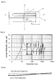
- FIG. 22 is a diagram showing the relationship between a proportion "f_1/d_1" of the driving length, obtained from the analysis described above, in the entire length and a sound pressure deviation "D_sp1" (corresponding to "D_sp1" in FIG. 19 ). As shown in FIG. 22 , it is understood that when 60% or more of the entire diaphragm is driven, the sound pressure deviation falls within 3 dB, which is considered desirable.
- FIG. 23 is a diagram showing the result of verifying by actual measurement, and comparing, the JISBOX characteristics of the loudspeaker 10 according to the first embodiment and a cone-shaped loudspeaker having the same diameter.
- the loudspeaker 10 according to the first embodiment generally has fewer variations of sound pressure than those of the cone-shaped loudspeaker having the same diameter, and has a wide range of frequencies at which sound pressure is relatively stable.
- the loudspeaker 10 is an excellent loudspeaker having high sound quality with a wide reproduction bandwidth.
- the loudspeaker according to the present invention is capable of suppressing break-up resonances and has high sound quality even with its elongated and thin structure, and therefore is effective particularly if incorporated in an electronic device.
- FIG. 24 is a diagram showing a television 1 having mounted therein the loudspeaker according to the present invention.
- the television 1 is a thin television such as a liquid crystal television or a plasma television, and includes any one type (the loudspeaker 10, in FIG. 24 ) of the loudspeaker according to the present invention on both sides of the screen.
- FIG. 25 is a diagram showing an automobile 2 having mounted therein the loudspeaker according to the present invention.
- the automobile 2 includes any one type (the loudspeaker 10, in FIG. 25 ) of the loudspeaker according to the present invention, in front left, front right, rear left, and rear right pillars.
- the loudspeaker according to the present invention is efficient in space since the loudspeaker has high sound quality yet is small in width and thickness.
- the loudspeaker when mounted in an electronic device such as a thin television, a mobile phone, a PDA, or an automobile, the loudspeaker can facilitate the reduction in width and thickness of the entire device, or can be mounted in a small space, and therefore is useful and has great industrial usefulness.
Landscapes
- Engineering & Computer Science (AREA)
- Physics & Mathematics (AREA)
- Acoustics & Sound (AREA)
- Signal Processing (AREA)
- Multimedia (AREA)
- Audible-Bandwidth Dynamoelectric Transducers Other Than Pickups (AREA)
- Diaphragms For Electromechanical Transducers (AREA)
Applications Claiming Priority (2)
| Application Number | Priority Date | Filing Date | Title |
|---|---|---|---|
| JP2008295207 | 2008-11-19 | ||
| PCT/JP2009/006162 WO2010058556A1 (fr) | 2008-11-19 | 2009-11-17 | Haut-parleur et dispositif électronique comprenant un haut-parleur |
Publications (3)
| Publication Number | Publication Date |
|---|---|
| EP2348754A1 true EP2348754A1 (fr) | 2011-07-27 |
| EP2348754A4 EP2348754A4 (fr) | 2013-09-11 |
| EP2348754B1 EP2348754B1 (fr) | 2017-01-25 |
Family
ID=42197999
Family Applications (1)
| Application Number | Title | Priority Date | Filing Date |
|---|---|---|---|
| EP09827337.8A Active EP2348754B1 (fr) | 2008-11-19 | 2009-11-17 | Haut-parleur et dispositif électronique comprenant un haut-parleur |
Country Status (4)
| Country | Link |
|---|---|
| US (1) | US8422723B2 (fr) |
| EP (1) | EP2348754B1 (fr) |
| JP (1) | JP5372012B2 (fr) |
| WO (1) | WO2010058556A1 (fr) |
Cited By (2)
| Publication number | Priority date | Publication date | Assignee | Title |
|---|---|---|---|---|
| US10009682B2 (en) | 2015-10-06 | 2018-06-26 | Sound Solutions International Co., Ltd. | Electroacoustic transducer |
| US11381921B2 (en) | 2018-10-30 | 2022-07-05 | Sound Solutions International Co., Ltd. | Electrodynamic acoustic transducer with improved suspension system |
Families Citing this family (25)
| Publication number | Priority date | Publication date | Assignee | Title |
|---|---|---|---|---|
| GB2460874B (en) * | 2008-06-13 | 2010-11-03 | Geco Technology Bv | Position determination of a seismic source array |
| US9185491B2 (en) * | 2011-04-12 | 2015-11-10 | Harman International Industries, Incorporated | Reinforced diaphragm for a low profile loudspeaker transducer with two sets of inner and outer magnets |
| WO2013009991A1 (fr) * | 2011-07-12 | 2013-01-17 | Strata Audio LLC | Raidisseur de support de bobine acoustique |
| JP2015090271A (ja) * | 2013-11-05 | 2015-05-11 | 日立オートモティブシステムズ株式会社 | 慣性力センサ装置 |
| CN105684464A (zh) | 2014-07-04 | 2016-06-15 | 松下知识产权经营株式会社 | 扬声器和搭载有该扬声器的移动体装置 |
| DE102014219630A1 (de) * | 2014-09-26 | 2016-03-31 | Sennheiser Electronic Gmbh & Co. Kg | Elektrodynamischer Schallwandler |
| USRE49437E1 (en) | 2014-09-30 | 2023-02-28 | Apple Inc. | Audio driver and power supply unit architecture |
| EP3416406A1 (fr) | 2014-09-30 | 2018-12-19 | Apple Inc. | Haut-parleur à coloration audio réduite causée par des réflexions à partir d'une surface |
| US20170318391A1 (en) * | 2014-11-08 | 2017-11-02 | Slivice Co., Ltd | Diaphragm for speaker apparatus |
| CN107113522B (zh) * | 2015-01-08 | 2020-06-09 | 韩国技术教育大学产学协力团 | 传声器 |
| KR102361288B1 (ko) | 2015-03-13 | 2022-02-10 | 삼성전자주식회사 | 스피커 장치 |
| CN204733374U (zh) * | 2015-06-23 | 2015-10-28 | 瑞声光电科技(常州)有限公司 | 扬声器 |
| CN204741558U (zh) * | 2015-06-23 | 2015-11-04 | 瑞声光电科技(常州)有限公司 | 扬声器 |
| US10257608B2 (en) | 2016-09-23 | 2019-04-09 | Apple Inc. | Subwoofer with multi-lobe magnet |
| CN206596208U (zh) * | 2017-02-13 | 2017-10-27 | 歌尔股份有限公司 | 发声装置中音圈的连接结构及发声装置 |
| JP7217238B2 (ja) * | 2017-06-09 | 2023-02-02 | アスク インダストリーズ ソシエタ ペル アツィオーニ | スピーカ構造 |
| KR102312266B1 (ko) * | 2017-08-03 | 2021-10-12 | 엘지디스플레이 주식회사 | 표시장치 |
| CN110418256B (zh) * | 2018-04-27 | 2022-03-11 | 歌尔股份有限公司 | 发声装置单体、发声模组及电子终端 |
| CN108632728B (zh) * | 2018-06-25 | 2020-08-11 | 歌尔股份有限公司 | 发声器件及便携终端 |
| CN109819382A (zh) * | 2018-12-30 | 2019-05-28 | 瑞声声学科技(深圳)有限公司 | 扬声器 |
| CN109862484B (zh) * | 2018-12-30 | 2021-10-01 | 瑞声声学科技(深圳)有限公司 | 一种扬声器 |
| RU199095U1 (ru) * | 2020-03-11 | 2020-08-13 | Общество С Ограниченной Ответственностью "Яндекс" | Умная колонка с узлом регулировки громкости для устранения вибраций в регуляторе громкости умной колонки |
| CN113411728B (zh) * | 2021-06-11 | 2022-11-29 | 美特科技(苏州)有限公司 | 振膜组件、扬声器模组和电子设备 |
| CN113784243B (zh) * | 2021-08-31 | 2023-07-25 | 歌尔科技有限公司 | 一种喇叭模组和头戴设备 |
| EP4228286A1 (fr) * | 2022-02-11 | 2023-08-16 | mateligent GmbH | Dispositif transducteur audio-tactile basé sur des élastomères diélectriques électro-actifs |
Citations (2)
| Publication number | Priority date | Publication date | Assignee | Title |
|---|---|---|---|---|
| US4699242A (en) * | 1984-12-28 | 1987-10-13 | Daikin Trade & Industry Co., Ltd. | Magnetic speaker |
| EP1750477A1 (fr) * | 2004-05-27 | 2007-02-07 | Matsushita Electric Industrial Co., Ltd. | Haut-parleur |
Family Cites Families (49)
| Publication number | Priority date | Publication date | Assignee | Title |
|---|---|---|---|---|
| JPS5518156A (en) * | 1978-07-25 | 1980-02-08 | Matsushita Electric Ind Co Ltd | Speaker |
| EP0018780B1 (fr) | 1979-04-30 | 1983-08-03 | Manchem Limited | Complexe d'aluminium, méthode pour sa préparation et compositions séchant à l'air qui le contiennent |
| JPS568393U (fr) * | 1979-06-30 | 1981-01-24 | ||
| DE3024729C2 (de) * | 1979-06-30 | 1982-11-18 | Pioneer Electronic Corp., Tokyo | Schwingspulenkörper für eine planare Membran |
| JPS5927159B2 (ja) * | 1980-04-02 | 1984-07-03 | 松下電器産業株式会社 | 動電型スピ−カ |
| US4414158A (en) | 1980-04-29 | 1983-11-08 | Ciba-Geigy Corporation | Phosphonomethylglycylhydroxamic acid and novel herbicidally active salts thereof |
| JPS56169696U (fr) * | 1980-05-19 | 1981-12-15 | ||
| JPS57136895A (en) | 1981-02-18 | 1982-08-24 | Mitsubishi Electric Corp | Speaker |
| NL8200416A (nl) * | 1982-02-04 | 1983-09-01 | Philips Nv | Vlakmembraan omzetter en werkwijze voor het vervaardigen van een dergelijke omzetter. |
| NL8200690A (nl) * | 1982-02-22 | 1983-09-16 | Philips Nv | Luidsprekermembraan bevattende een laag van polymethacrylimideschuim. |
| JPS58222700A (ja) * | 1982-06-18 | 1983-12-24 | Matsushita Electric Ind Co Ltd | 平面スピ−カ |
| JPS5932292A (ja) * | 1982-08-16 | 1984-02-21 | Hitachi Ltd | スピ−カ |
| JPS59171399A (ja) * | 1983-03-18 | 1984-09-27 | Toshiba Corp | 平板形スピ−カ装置 |
| JPS60128799A (ja) * | 1983-12-15 | 1985-07-09 | Matsushita Electric Ind Co Ltd | スピ−カ |
| JPS60167596A (ja) * | 1984-02-09 | 1985-08-30 | Matsushita Electric Ind Co Ltd | 平板スピ−カ |
| JPS60219896A (ja) * | 1984-04-17 | 1985-11-02 | Matsushita Electric Ind Co Ltd | 平面スピ−カ |
| JPS60219899A (ja) * | 1984-04-17 | 1985-11-02 | Matsushita Electric Ind Co Ltd | スピ−カ |
| JPS61121695A (ja) | 1984-11-19 | 1986-06-09 | Matsushita Electric Ind Co Ltd | スピ−カ用ボイスコイル |
| US4635750A (en) * | 1985-06-03 | 1987-01-13 | Sharp Kabushiki Kaisha | Loudspeaker diaphragm |
| JPS62237900A (ja) * | 1986-04-09 | 1987-10-17 | Matsushita Electric Ind Co Ltd | 平面スピ−カユニツト |
| JPS6342299A (ja) * | 1986-08-07 | 1988-02-23 | Mitsubishi Electric Corp | 平板スピ−カ− |
| US4899390A (en) * | 1986-09-19 | 1990-02-06 | Matsushita Electric Industrial Co., Ltd. | Thin speaker having an enclosure within an open portion and a closed portion |
| JPS63246100A (ja) * | 1987-04-01 | 1988-10-13 | Matsushita Electric Ind Co Ltd | 矩形平面スピ−カ |
| JPS6427399A (en) * | 1987-07-23 | 1989-01-30 | Matsushita Electric Ind Co Ltd | Rectangular flat speaker |
| JPH01108900A (ja) * | 1987-10-21 | 1989-04-26 | Matsushita Electric Ind Co Ltd | 振動板 |
| DE9109452U1 (fr) * | 1991-07-31 | 1991-10-17 | Nokia Unterhaltungselektronik (Deutschland) Gmbh, 7530 Pforzheim, De | |
| JP2897592B2 (ja) | 1992-05-28 | 1999-05-31 | 住友化学工業株式会社 | 低重合度パラアラミドドープ、それから製造されるパラアラミド繊維およびパラアラミドパルプならびにそれらの製造方法 |
| JPH0641298U (ja) * | 1992-11-02 | 1994-05-31 | 鈴木管紙株式会社 | ボイスコイル・ボビン |
| JP3139915B2 (ja) | 1994-04-25 | 2001-03-05 | 松下電器産業株式会社 | スピーカ |
| JP3136959B2 (ja) * | 1995-08-31 | 2001-02-19 | 松下電器産業株式会社 | スピーカ |
| JP3569413B2 (ja) * | 1997-03-25 | 2004-09-22 | パイオニア株式会社 | スピーカ装置及びスピーカ装置の製造方法 |
| JP3820717B2 (ja) | 1997-12-19 | 2006-09-13 | 松下電器産業株式会社 | スピーカ |
| JP3812150B2 (ja) * | 1998-06-18 | 2006-08-23 | 松下電器産業株式会社 | スピーカ |
| JP2001211497A (ja) | 2000-01-27 | 2001-08-03 | Matsushita Electric Ind Co Ltd | スピーカ |
| JP3942813B2 (ja) * | 2000-08-03 | 2007-07-11 | パイオニア株式会社 | スピーカおよびその組立方法 |
| US6654475B2 (en) * | 2000-09-29 | 2003-11-25 | Victor Company Of Japan, Ltd. | Electricity-to-sound transducer |
| JP4000793B2 (ja) | 2001-07-13 | 2007-10-31 | オリエントサウンド株式会社 | 角形スピーカ |
| JP3915448B2 (ja) * | 2001-07-30 | 2007-05-16 | 日本ビクター株式会社 | 電気音響変換器 |
| JP3896862B2 (ja) | 2002-02-20 | 2007-03-22 | 松下電器産業株式会社 | スピーカ |
| JP3888443B2 (ja) | 2002-03-12 | 2007-03-07 | ヤマハ株式会社 | フィルム状コイルを用いた電気音響変換器 |
| EP1377115B1 (fr) * | 2002-06-24 | 2016-01-06 | Panasonic Intellectual Property Management Co., Ltd. | Membrane de haut-parleur |
| US7333620B2 (en) * | 2003-04-09 | 2008-02-19 | Harman International Industries, Incorporated | Acoustic transducer with mechanical balancing |
| JP3725528B2 (ja) | 2003-06-20 | 2005-12-14 | 古河電気工業株式会社 | 平面スピーカ |
| JP4248452B2 (ja) | 2004-06-16 | 2009-04-02 | シャープ株式会社 | スピーカ |
| US20070160257A1 (en) * | 2005-04-13 | 2007-07-12 | Stiles Enrique M | Axial magnet assisted radial magnet air return motor for electromagnetic transducer |
| KR101156366B1 (ko) * | 2005-05-25 | 2012-06-13 | 놀레스 일렉트로닉스 아시아 피티이 리미티드 | 멤브레인, 이를 포함하는 트랜스듀서 및 트랜스듀서를 포함하는 장치 |
| KR100888965B1 (ko) * | 2006-06-29 | 2009-03-17 | 엘지전자 주식회사 | 스피커 |
| US7848536B2 (en) * | 2007-11-02 | 2010-12-07 | Onkyo Corporation | Voice coil assembly, loudspeaker using the same, and method for producing the same |
| EP2244488B1 (fr) * | 2008-02-14 | 2015-07-29 | Panasonic Intellectual Property Management Co., Ltd. | Haut-parleur et appareil électronique |
-
2009
- 2009-11-17 EP EP09827337.8A patent/EP2348754B1/fr active Active
- 2009-11-17 WO PCT/JP2009/006162 patent/WO2010058556A1/fr active Application Filing
- 2009-11-17 US US12/812,824 patent/US8422723B2/en active Active
- 2009-11-17 JP JP2010539140A patent/JP5372012B2/ja active Active
Patent Citations (2)
| Publication number | Priority date | Publication date | Assignee | Title |
|---|---|---|---|---|
| US4699242A (en) * | 1984-12-28 | 1987-10-13 | Daikin Trade & Industry Co., Ltd. | Magnetic speaker |
| EP1750477A1 (fr) * | 2004-05-27 | 2007-02-07 | Matsushita Electric Industrial Co., Ltd. | Haut-parleur |
Non-Patent Citations (1)
| Title |
|---|
| See also references of WO2010058556A1 * |
Cited By (2)
| Publication number | Priority date | Publication date | Assignee | Title |
|---|---|---|---|---|
| US10009682B2 (en) | 2015-10-06 | 2018-06-26 | Sound Solutions International Co., Ltd. | Electroacoustic transducer |
| US11381921B2 (en) | 2018-10-30 | 2022-07-05 | Sound Solutions International Co., Ltd. | Electrodynamic acoustic transducer with improved suspension system |
Also Published As
| Publication number | Publication date |
|---|---|
| JP5372012B2 (ja) | 2013-12-18 |
| US8422723B2 (en) | 2013-04-16 |
| JPWO2010058556A1 (ja) | 2012-04-19 |
| EP2348754A4 (fr) | 2013-09-11 |
| EP2348754B1 (fr) | 2017-01-25 |
| US20110211725A1 (en) | 2011-09-01 |
| WO2010058556A1 (fr) | 2010-05-27 |
Similar Documents
| Publication | Publication Date | Title |
|---|---|---|
| US8422723B2 (en) | Loudspeaker and electronic device including loudspeaker | |
| JP4590403B2 (ja) | スピーカ | |
| US8553926B2 (en) | Speaker and electronic device | |
| US8094864B2 (en) | Diaphragm unit and speaker using the same | |
| KR101061550B1 (ko) | 장방형 서스펜션 및 이를 채용한 스피커 모듈 | |
| JP3136959B2 (ja) | スピーカ | |
| JP2003047089A (ja) | 電気音響変換器 | |
| JPH10191494A (ja) | スピーカ | |
| WO2012063490A1 (fr) | Haut-parleur et dispositif audio doté de ce haut-parleur | |
| JP5849197B2 (ja) | スピーカ、および、それを備える電子機器 | |
| KR101560365B1 (ko) | 스피커 장치의 진동판 | |
| US8879776B2 (en) | Speaker and electronic device using the speaker | |
| JP3139915B2 (ja) | スピーカ | |
| JP4189816B2 (ja) | 電気音響変換器 | |
| JP2010199812A (ja) | スピーカー振動板およびこれを用いたスピーカー | |
| JP5950261B2 (ja) | スピーカおよびスピーカを備えた電子機器 | |
| JP3132323B2 (ja) | スピーカとその製造方法 | |
| JP2002325294A (ja) | 電気音響変換器 | |
| JP3767441B2 (ja) | 電気音響変換器 | |
| JPH09284889A (ja) | スピーカ | |
| JP2011239125A (ja) | エッジおよびこれを用いた動電型スピーカー | |
| JP2001008286A (ja) | スピーカ | |
| JP2010103894A (ja) | 電気音響変換装置 |
Legal Events
| Date | Code | Title | Description |
|---|---|---|---|
| PUAI | Public reference made under article 153(3) epc to a published international application that has entered the european phase |
Free format text: ORIGINAL CODE: 0009012 |
|
| 17P | Request for examination filed |
Effective date: 20100716 |
|
| AK | Designated contracting states |
Kind code of ref document: A1 Designated state(s): AT BE BG CH CY CZ DE DK EE ES FI FR GB GR HR HU IE IS IT LI LT LU LV MC MK MT NL NO PL PT RO SE SI SK SM TR |
|
| AX | Request for extension of the european patent |
Extension state: AL BA RS |
|
| DAX | Request for extension of the european patent (deleted) | ||
| A4 | Supplementary search report drawn up and despatched |
Effective date: 20130809 |
|
| RIC1 | Information provided on ipc code assigned before grant |
Ipc: H04R 9/04 20060101AFI20130805BHEP Ipc: H04R 9/02 20060101ALI20130805BHEP Ipc: H04R 7/04 20060101ALI20130805BHEP Ipc: H04R 9/06 20060101ALI20130805BHEP |
|
| RAP1 | Party data changed (applicant data changed or rights of an application transferred) |
Owner name: PANASONIC INTELLECTUAL PROPERTY MANAGEMENT CO., LT |
|
| GRAP | Despatch of communication of intention to grant a patent |
Free format text: ORIGINAL CODE: EPIDOSNIGR1 |
|
| STAA | Information on the status of an ep patent application or granted ep patent |
Free format text: STATUS: GRANT OF PATENT IS INTENDED |
|
| INTG | Intention to grant announced |
Effective date: 20161107 |
|
| GRAS | Grant fee paid |
Free format text: ORIGINAL CODE: EPIDOSNIGR3 |
|
| GRAA | (expected) grant |
Free format text: ORIGINAL CODE: 0009210 |
|
| STAA | Information on the status of an ep patent application or granted ep patent |
Free format text: STATUS: THE PATENT HAS BEEN GRANTED |
|
| AK | Designated contracting states |
Kind code of ref document: B1 Designated state(s): AT BE BG CH CY CZ DE DK EE ES FI FR GB GR HR HU IE IS IT LI LT LU LV MC MK MT NL NO PL PT RO SE SI SK SM TR |
|
| REG | Reference to a national code |
Ref country code: GB Ref legal event code: FG4D |
|
| REG | Reference to a national code |
Ref country code: CH Ref legal event code: EP |
|
| REG | Reference to a national code |
Ref country code: AT Ref legal event code: REF Ref document number: 864732 Country of ref document: AT Kind code of ref document: T Effective date: 20170215 |
|
| REG | Reference to a national code |
Ref country code: IE Ref legal event code: FG4D |
|
| REG | Reference to a national code |
Ref country code: DE Ref legal event code: R096 Ref document number: 602009044009 Country of ref document: DE |
|
| REG | Reference to a national code |
Ref country code: LT Ref legal event code: MG4D |
|
| REG | Reference to a national code |
Ref country code: NL Ref legal event code: MP Effective date: 20170125 |
|
| REG | Reference to a national code |
Ref country code: AT Ref legal event code: MK05 Ref document number: 864732 Country of ref document: AT Kind code of ref document: T Effective date: 20170125 |
|
| PG25 | Lapsed in a contracting state [announced via postgrant information from national office to epo] |
Ref country code: NL Free format text: LAPSE BECAUSE OF FAILURE TO SUBMIT A TRANSLATION OF THE DESCRIPTION OR TO PAY THE FEE WITHIN THE PRESCRIBED TIME-LIMIT Effective date: 20170125 |
|
| PG25 | Lapsed in a contracting state [announced via postgrant information from national office to epo] |
Ref country code: IS Free format text: LAPSE BECAUSE OF FAILURE TO SUBMIT A TRANSLATION OF THE DESCRIPTION OR TO PAY THE FEE WITHIN THE PRESCRIBED TIME-LIMIT Effective date: 20170525 Ref country code: NO Free format text: LAPSE BECAUSE OF FAILURE TO SUBMIT A TRANSLATION OF THE DESCRIPTION OR TO PAY THE FEE WITHIN THE PRESCRIBED TIME-LIMIT Effective date: 20170425 Ref country code: HR Free format text: LAPSE BECAUSE OF FAILURE TO SUBMIT A TRANSLATION OF THE DESCRIPTION OR TO PAY THE FEE WITHIN THE PRESCRIBED TIME-LIMIT Effective date: 20170125 Ref country code: GR Free format text: LAPSE BECAUSE OF FAILURE TO SUBMIT A TRANSLATION OF THE DESCRIPTION OR TO PAY THE FEE WITHIN THE PRESCRIBED TIME-LIMIT Effective date: 20170426 Ref country code: LT Free format text: LAPSE BECAUSE OF FAILURE TO SUBMIT A TRANSLATION OF THE DESCRIPTION OR TO PAY THE FEE WITHIN THE PRESCRIBED TIME-LIMIT Effective date: 20170125 Ref country code: FI Free format text: LAPSE BECAUSE OF FAILURE TO SUBMIT A TRANSLATION OF THE DESCRIPTION OR TO PAY THE FEE WITHIN THE PRESCRIBED TIME-LIMIT Effective date: 20170125 |
|
| PG25 | Lapsed in a contracting state [announced via postgrant information from national office to epo] |
Ref country code: AT Free format text: LAPSE BECAUSE OF FAILURE TO SUBMIT A TRANSLATION OF THE DESCRIPTION OR TO PAY THE FEE WITHIN THE PRESCRIBED TIME-LIMIT Effective date: 20170125 Ref country code: LV Free format text: LAPSE BECAUSE OF FAILURE TO SUBMIT A TRANSLATION OF THE DESCRIPTION OR TO PAY THE FEE WITHIN THE PRESCRIBED TIME-LIMIT Effective date: 20170125 Ref country code: BG Free format text: LAPSE BECAUSE OF FAILURE TO SUBMIT A TRANSLATION OF THE DESCRIPTION OR TO PAY THE FEE WITHIN THE PRESCRIBED TIME-LIMIT Effective date: 20170425 Ref country code: ES Free format text: LAPSE BECAUSE OF FAILURE TO SUBMIT A TRANSLATION OF THE DESCRIPTION OR TO PAY THE FEE WITHIN THE PRESCRIBED TIME-LIMIT Effective date: 20170125 Ref country code: PL Free format text: LAPSE BECAUSE OF FAILURE TO SUBMIT A TRANSLATION OF THE DESCRIPTION OR TO PAY THE FEE WITHIN THE PRESCRIBED TIME-LIMIT Effective date: 20170125 Ref country code: PT Free format text: LAPSE BECAUSE OF FAILURE TO SUBMIT A TRANSLATION OF THE DESCRIPTION OR TO PAY THE FEE WITHIN THE PRESCRIBED TIME-LIMIT Effective date: 20170525 Ref country code: SE Free format text: LAPSE BECAUSE OF FAILURE TO SUBMIT A TRANSLATION OF THE DESCRIPTION OR TO PAY THE FEE WITHIN THE PRESCRIBED TIME-LIMIT Effective date: 20170125 |
|
| REG | Reference to a national code |
Ref country code: DE Ref legal event code: R097 Ref document number: 602009044009 Country of ref document: DE |
|
| PG25 | Lapsed in a contracting state [announced via postgrant information from national office to epo] |
Ref country code: CZ Free format text: LAPSE BECAUSE OF FAILURE TO SUBMIT A TRANSLATION OF THE DESCRIPTION OR TO PAY THE FEE WITHIN THE PRESCRIBED TIME-LIMIT Effective date: 20170125 Ref country code: EE Free format text: LAPSE BECAUSE OF FAILURE TO SUBMIT A TRANSLATION OF THE DESCRIPTION OR TO PAY THE FEE WITHIN THE PRESCRIBED TIME-LIMIT Effective date: 20170125 Ref country code: SK Free format text: LAPSE BECAUSE OF FAILURE TO SUBMIT A TRANSLATION OF THE DESCRIPTION OR TO PAY THE FEE WITHIN THE PRESCRIBED TIME-LIMIT Effective date: 20170125 Ref country code: RO Free format text: LAPSE BECAUSE OF FAILURE TO SUBMIT A TRANSLATION OF THE DESCRIPTION OR TO PAY THE FEE WITHIN THE PRESCRIBED TIME-LIMIT Effective date: 20170125 Ref country code: IT Free format text: LAPSE BECAUSE OF FAILURE TO SUBMIT A TRANSLATION OF THE DESCRIPTION OR TO PAY THE FEE WITHIN THE PRESCRIBED TIME-LIMIT Effective date: 20170125 |
|
| PG25 | Lapsed in a contracting state [announced via postgrant information from national office to epo] |
Ref country code: SM Free format text: LAPSE BECAUSE OF FAILURE TO SUBMIT A TRANSLATION OF THE DESCRIPTION OR TO PAY THE FEE WITHIN THE PRESCRIBED TIME-LIMIT Effective date: 20170125 Ref country code: DK Free format text: LAPSE BECAUSE OF FAILURE TO SUBMIT A TRANSLATION OF THE DESCRIPTION OR TO PAY THE FEE WITHIN THE PRESCRIBED TIME-LIMIT Effective date: 20170125 |
|
| PLBE | No opposition filed within time limit |
Free format text: ORIGINAL CODE: 0009261 |
|
| STAA | Information on the status of an ep patent application or granted ep patent |
Free format text: STATUS: NO OPPOSITION FILED WITHIN TIME LIMIT |
|
| 26N | No opposition filed |
Effective date: 20171026 |
|
| PG25 | Lapsed in a contracting state [announced via postgrant information from national office to epo] |
Ref country code: SI Free format text: LAPSE BECAUSE OF FAILURE TO SUBMIT A TRANSLATION OF THE DESCRIPTION OR TO PAY THE FEE WITHIN THE PRESCRIBED TIME-LIMIT Effective date: 20170125 |
|
| PG25 | Lapsed in a contracting state [announced via postgrant information from national office to epo] |
Ref country code: MC Free format text: LAPSE BECAUSE OF FAILURE TO SUBMIT A TRANSLATION OF THE DESCRIPTION OR TO PAY THE FEE WITHIN THE PRESCRIBED TIME-LIMIT Effective date: 20170125 |
|
| GBPC | Gb: european patent ceased through non-payment of renewal fee |
Effective date: 20171117 |
|
| PG25 | Lapsed in a contracting state [announced via postgrant information from national office to epo] |
Ref country code: LI Free format text: LAPSE BECAUSE OF NON-PAYMENT OF DUE FEES Effective date: 20171130 Ref country code: CH Free format text: LAPSE BECAUSE OF NON-PAYMENT OF DUE FEES Effective date: 20171130 |
|
| PG25 | Lapsed in a contracting state [announced via postgrant information from national office to epo] |
Ref country code: LU Free format text: LAPSE BECAUSE OF NON-PAYMENT OF DUE FEES Effective date: 20171117 |
|
| REG | Reference to a national code |
Ref country code: FR Ref legal event code: ST Effective date: 20180731 Ref country code: BE Ref legal event code: MM Effective date: 20171130 |
|
| REG | Reference to a national code |
Ref country code: IE Ref legal event code: MM4A |
|
| PG25 | Lapsed in a contracting state [announced via postgrant information from national office to epo] |
Ref country code: MT Free format text: LAPSE BECAUSE OF NON-PAYMENT OF DUE FEES Effective date: 20171117 |
|
| PG25 | Lapsed in a contracting state [announced via postgrant information from national office to epo] |
Ref country code: FR Free format text: LAPSE BECAUSE OF NON-PAYMENT OF DUE FEES Effective date: 20171130 Ref country code: IE Free format text: LAPSE BECAUSE OF NON-PAYMENT OF DUE FEES Effective date: 20171117 |
|
| PG25 | Lapsed in a contracting state [announced via postgrant information from national office to epo] |
Ref country code: GB Free format text: LAPSE BECAUSE OF NON-PAYMENT OF DUE FEES Effective date: 20171117 Ref country code: BE Free format text: LAPSE BECAUSE OF NON-PAYMENT OF DUE FEES Effective date: 20171130 |
|
| PG25 | Lapsed in a contracting state [announced via postgrant information from national office to epo] |
Ref country code: HU Free format text: LAPSE BECAUSE OF FAILURE TO SUBMIT A TRANSLATION OF THE DESCRIPTION OR TO PAY THE FEE WITHIN THE PRESCRIBED TIME-LIMIT; INVALID AB INITIO Effective date: 20091117 |
|
| PG25 | Lapsed in a contracting state [announced via postgrant information from national office to epo] |
Ref country code: CY Free format text: LAPSE BECAUSE OF NON-PAYMENT OF DUE FEES Effective date: 20170125 |
|
| PG25 | Lapsed in a contracting state [announced via postgrant information from national office to epo] |
Ref country code: MK Free format text: LAPSE BECAUSE OF FAILURE TO SUBMIT A TRANSLATION OF THE DESCRIPTION OR TO PAY THE FEE WITHIN THE PRESCRIBED TIME-LIMIT Effective date: 20170125 |
|
| PG25 | Lapsed in a contracting state [announced via postgrant information from national office to epo] |
Ref country code: TR Free format text: LAPSE BECAUSE OF FAILURE TO SUBMIT A TRANSLATION OF THE DESCRIPTION OR TO PAY THE FEE WITHIN THE PRESCRIBED TIME-LIMIT Effective date: 20170125 |
|
| PGFP | Annual fee paid to national office [announced via postgrant information from national office to epo] |
Ref country code: DE Payment date: 20231121 Year of fee payment: 15 |