EP2308539B1 - Dispositif pour délivrer un gaz respiratoire, humidificateur, tube respiratoire, et dispositif de connection - Google Patents
Dispositif pour délivrer un gaz respiratoire, humidificateur, tube respiratoire, et dispositif de connection Download PDFInfo
- Publication number
- EP2308539B1 EP2308539B1 EP10185455.2A EP10185455A EP2308539B1 EP 2308539 B1 EP2308539 B1 EP 2308539B1 EP 10185455 A EP10185455 A EP 10185455A EP 2308539 B1 EP2308539 B1 EP 2308539B1
- Authority
- EP
- European Patent Office
- Prior art keywords
- humidifying
- respiratory gas
- set forth
- supplying
- cpap
- Prior art date
- Legal status (The legal status is an assumption and is not a legal conclusion. Google has not performed a legal analysis and makes no representation as to the accuracy of the status listed.)
- Expired - Lifetime
Links
Images


Classifications
-
- A—HUMAN NECESSITIES
- A61—MEDICAL OR VETERINARY SCIENCE; HYGIENE
- A61M—DEVICES FOR INTRODUCING MEDIA INTO, OR ONTO, THE BODY; DEVICES FOR TRANSDUCING BODY MEDIA OR FOR TAKING MEDIA FROM THE BODY; DEVICES FOR PRODUCING OR ENDING SLEEP OR STUPOR
- A61M16/00—Devices for influencing the respiratory system of patients by gas treatment, e.g. mouth-to-mouth respiration; Tracheal tubes
- A61M16/10—Preparation of respiratory gases or vapours
- A61M16/14—Preparation of respiratory gases or vapours by mixing different fluids, one of them being in a liquid phase
- A61M16/16—Devices to humidify the respiration air
-
- A—HUMAN NECESSITIES
- A61—MEDICAL OR VETERINARY SCIENCE; HYGIENE
- A61M—DEVICES FOR INTRODUCING MEDIA INTO, OR ONTO, THE BODY; DEVICES FOR TRANSDUCING BODY MEDIA OR FOR TAKING MEDIA FROM THE BODY; DEVICES FOR PRODUCING OR ENDING SLEEP OR STUPOR
- A61M16/00—Devices for influencing the respiratory system of patients by gas treatment, e.g. mouth-to-mouth respiration; Tracheal tubes
- A61M16/0057—Pumps therefor
- A61M16/0066—Blowers or centrifugal pumps
-
- A—HUMAN NECESSITIES
- A61—MEDICAL OR VETERINARY SCIENCE; HYGIENE
- A61M—DEVICES FOR INTRODUCING MEDIA INTO, OR ONTO, THE BODY; DEVICES FOR TRANSDUCING BODY MEDIA OR FOR TAKING MEDIA FROM THE BODY; DEVICES FOR PRODUCING OR ENDING SLEEP OR STUPOR
- A61M16/00—Devices for influencing the respiratory system of patients by gas treatment, e.g. mouth-to-mouth respiration; Tracheal tubes
- A61M16/08—Bellows; Connecting tubes ; Water traps; Patient circuits
- A61M16/0816—Joints or connectors
- A61M16/0841—Joints or connectors for sampling
- A61M16/0858—Pressure sampling ports
-
- A—HUMAN NECESSITIES
- A61—MEDICAL OR VETERINARY SCIENCE; HYGIENE
- A61M—DEVICES FOR INTRODUCING MEDIA INTO, OR ONTO, THE BODY; DEVICES FOR TRANSDUCING BODY MEDIA OR FOR TAKING MEDIA FROM THE BODY; DEVICES FOR PRODUCING OR ENDING SLEEP OR STUPOR
- A61M16/00—Devices for influencing the respiratory system of patients by gas treatment, e.g. mouth-to-mouth respiration; Tracheal tubes
- A61M16/08—Bellows; Connecting tubes ; Water traps; Patient circuits
- A61M16/0875—Connecting tubes
-
- A—HUMAN NECESSITIES
- A61—MEDICAL OR VETERINARY SCIENCE; HYGIENE
- A61M—DEVICES FOR INTRODUCING MEDIA INTO, OR ONTO, THE BODY; DEVICES FOR TRANSDUCING BODY MEDIA OR FOR TAKING MEDIA FROM THE BODY; DEVICES FOR PRODUCING OR ENDING SLEEP OR STUPOR
- A61M16/00—Devices for influencing the respiratory system of patients by gas treatment, e.g. mouth-to-mouth respiration; Tracheal tubes
- A61M16/10—Preparation of respiratory gases or vapours
- A61M16/105—Filters
-
- A—HUMAN NECESSITIES
- A61—MEDICAL OR VETERINARY SCIENCE; HYGIENE
- A61M—DEVICES FOR INTRODUCING MEDIA INTO, OR ONTO, THE BODY; DEVICES FOR TRANSDUCING BODY MEDIA OR FOR TAKING MEDIA FROM THE BODY; DEVICES FOR PRODUCING OR ENDING SLEEP OR STUPOR
- A61M16/00—Devices for influencing the respiratory system of patients by gas treatment, e.g. mouth-to-mouth respiration; Tracheal tubes
- A61M16/10—Preparation of respiratory gases or vapours
- A61M16/1075—Preparation of respiratory gases or vapours by influencing the temperature
- A61M16/109—Preparation of respiratory gases or vapours by influencing the temperature the humidifying liquid or the beneficial agent
-
- A—HUMAN NECESSITIES
- A61—MEDICAL OR VETERINARY SCIENCE; HYGIENE
- A61M—DEVICES FOR INTRODUCING MEDIA INTO, OR ONTO, THE BODY; DEVICES FOR TRANSDUCING BODY MEDIA OR FOR TAKING MEDIA FROM THE BODY; DEVICES FOR PRODUCING OR ENDING SLEEP OR STUPOR
- A61M16/00—Devices for influencing the respiratory system of patients by gas treatment, e.g. mouth-to-mouth respiration; Tracheal tubes
- A61M16/10—Preparation of respiratory gases or vapours
- A61M16/14—Preparation of respiratory gases or vapours by mixing different fluids, one of them being in a liquid phase
- A61M16/16—Devices to humidify the respiration air
- A61M16/162—Water-reservoir filling system, e.g. automatic
-
- A—HUMAN NECESSITIES
- A62—LIFE-SAVING; FIRE-FIGHTING
- A62B—DEVICES, APPARATUS OR METHODS FOR LIFE-SAVING
- A62B9/00—Component parts for respiratory or breathing apparatus
- A62B9/003—Means for influencing the temperature or humidity of the breathing gas
-
- A—HUMAN NECESSITIES
- A61—MEDICAL OR VETERINARY SCIENCE; HYGIENE
- A61M—DEVICES FOR INTRODUCING MEDIA INTO, OR ONTO, THE BODY; DEVICES FOR TRANSDUCING BODY MEDIA OR FOR TAKING MEDIA FROM THE BODY; DEVICES FOR PRODUCING OR ENDING SLEEP OR STUPOR
- A61M16/00—Devices for influencing the respiratory system of patients by gas treatment, e.g. mouth-to-mouth respiration; Tracheal tubes
- A61M16/10—Preparation of respiratory gases or vapours
- A61M16/105—Filters
- A61M16/106—Filters in a path
- A61M16/107—Filters in a path in the inspiratory path
-
- A—HUMAN NECESSITIES
- A61—MEDICAL OR VETERINARY SCIENCE; HYGIENE
- A61M—DEVICES FOR INTRODUCING MEDIA INTO, OR ONTO, THE BODY; DEVICES FOR TRANSDUCING BODY MEDIA OR FOR TAKING MEDIA FROM THE BODY; DEVICES FOR PRODUCING OR ENDING SLEEP OR STUPOR
- A61M16/00—Devices for influencing the respiratory system of patients by gas treatment, e.g. mouth-to-mouth respiration; Tracheal tubes
- A61M16/0003—Accessories therefor, e.g. sensors, vibrators, negative pressure
- A61M2016/0027—Accessories therefor, e.g. sensors, vibrators, negative pressure pressure meter
-
- A—HUMAN NECESSITIES
- A61—MEDICAL OR VETERINARY SCIENCE; HYGIENE
- A61M—DEVICES FOR INTRODUCING MEDIA INTO, OR ONTO, THE BODY; DEVICES FOR TRANSDUCING BODY MEDIA OR FOR TAKING MEDIA FROM THE BODY; DEVICES FOR PRODUCING OR ENDING SLEEP OR STUPOR
- A61M2205/00—General characteristics of the apparatus
- A61M2205/42—Reducing noise
-
- A—HUMAN NECESSITIES
- A61—MEDICAL OR VETERINARY SCIENCE; HYGIENE
- A61M—DEVICES FOR INTRODUCING MEDIA INTO, OR ONTO, THE BODY; DEVICES FOR TRANSDUCING BODY MEDIA OR FOR TAKING MEDIA FROM THE BODY; DEVICES FOR PRODUCING OR ENDING SLEEP OR STUPOR
- A61M2209/00—Ancillary equipment
- A61M2209/08—Supports for equipment
Definitions
- the invention relates to a device for supplying a breathing gas under pressure and a humidifying device for a device for supplying a breathing gas under pressure.
- a device for supplying a breathing gas under overpressure with a blower device for conveying the breathing gas, a housing device for receiving the blower device and a connecting device for connecting a moistening device for moistening the breathing gas conveyed by the conveyor is discussed. Furthermore, a humidification device for humidifying a respiratory gas and a breathing gas hose and a connection device for this purpose are discussed.
- WO 99/22793 A1 WO 98/57691 A1 and US 5,564,415 each discloses a device for supplying gas to a person and a humidifier.
- Devices for supplying a respiratory gas under overpressure are used, in particular, in the field of sleep therapy for the treatment of sleep-related respiratory disorders.
- a respiratory gas under a predetermined pressure usually in the range of 5-20 mbar
- a pneumatic splinting of the upper respiratory tract of a patient is achieved in a physiologically well tolerated manner, whereby an obstruction of this airway area can be effectively prevented.
- the breathing gas is formed directly from the preferably sucked by a filter device ambient air.
- a filter device ambient air.
- a humidifying device into the respiratory gas path between the fan device and the respiratory mask via a hose adapter.
- CPAP devices with integrated humidifying device There are also known CPAP devices with integrated humidifying device.
- the invention has for its object to provide a device for supplying a breathing gas and a designated humidification device that is robust and easy to handle and easily configured as needed.
- the connecting members are aligned substantially in the joining direction.
- the main passage cross-section for the promoted by the blower device breathing gas is advantageously formed by a pipe socket, on which a part of a corresponding complementary trained moistening device provided connection portion can be plugged.
- connection elements are formed in a device end face (front side).
- the surface portion of this device end face is formed substantially complementary to an adjacent in joining position portion of the moistening device.
- connection device has said pipe socket for the passage of the respiratory gas and a line section adjacently arranged for coupling a pressure measuring line.
- the pipe socket for the passage of the respiratory gas and the line section for the Druckmeß admir are arranged according to a particularly preferred embodiment of the invention in a recess such that they do not substantially over a defined by the front end face of the device main plane. As a result, a particularly effective protection of these comparatively filigree CPAP device connection organs is given.
- the terminal means comprises, as required, the moistening device electrical terminal means for establishing an electrical connection with the moistening device.
- the moistening device electrical terminal means for establishing an electrical connection with the moistening device.
- the electrical connection members can also be used for transmitting electrical signals, for example, for the transmission of a level signal or for transmitting electrical signals that have been supplied, for example in the breathing tube connection device.
- a particularly effective coupling of the CPAP device with the intended for connection thereto humidifying device according to the invention is achieved in that a manually releasable latching device is provided which holds the moistening device in a joining position.
- the CPAP device is acc. a particularly preferred embodiment of the invention in the bottom region formed such that the connecting members, in particular the said pipe socket are arranged at a vertical height level, which corresponds exactly to the height level of the moistening device provided by the connecting members.
- the side of the CPAP device and provided by the moistening device connecting members in the vertical direction are positioned so that when installing the CPAP device and the moistening device on a substantially flat surface, the moistening device can be pushed to the CPAP device , Wherein the required alignment of these two modules in the vertical direction is already achieved by the footprint.
- gem. a particularly preferred embodiment of the invention also provided centering.
- a particularly robust centering aid is in this case achieved by the inner wall of the pipe socket austecden recess is matched to the outer peripheral surface of the side provided by the moistening device connecting pin.
- a moistening device With regard to a moistening device, the object stated at the outset is achieved by a moistening device discussed herein.
- a moistening device can be coupled in a simple manner by a layman to a corresponding CPAP device, without that this requires a professional assembly technology or a connection hose.
- the CPAP device does not need to be raised for this purpose.
- a humidifier unit which can be coupled to a base unit which comprises a cartridge-like removable and reusable refill module.
- the refill module can be fixed in the humidifier unit via fixing devices, for example a bayonet closure device.
- the refill module can be partially or completely sealed in the humidifier.
- a spontaneous breathing of a patient is supported, by this a breathing gas is supplied under permanent overpressure.
- This overpressure achieves pneumatic upper airway splinting which can prevent any airway obstruction occurring during a patient's sleep phase.
- this positive pressure ventilation usually extends over the entire sleeping phase of the patient.
- the humidification of the respiratory gas is carried out by this is passed over a water bath and thereby absorbs moisture.
- this water bath usually a quantity of water of approx. 750ml is stored.
- the water bath is preferably heated slightly by means of a heater.
- an easy-to-handle device for humidifying a breathing gas and a CPAP device provided for use therewith are described, by which, or by which, a uniform humidification of the breathing gas can be achieved.
- a device for humidifying a respiratory gas with a liquid storage space for storing a liquid a humidification area for loading the respiratory gas with the liquid by the respiratory gas in the humidification area comes into contact with the liquid, a breathing gas supply means for supplying the respiratory gas to the humidification area, and a breathing gas discharge device for discharging the humidified respiratory gas from the humidification area, wherein a partial quantity delivery device is provided, for passing only a subset of the liquid stored in the liquid storage space into the humidification area.
- the moistening device according to the invention is particularly suitable for off-grid operation by means of battery or rechargeable battery.
- the humidification area is spatially separated from the liquid storage space.
- a fluid conduit device is preferably provided, via which the humidifying area communicates with the liquid storage space.
- a partition wall is provided which separates the humidification area from the liquid storage space.
- Said fluid conduit means is preferably arranged such that it passes through the partition wall.
- the level in the humidification area is advantageously metered by venting the liquid storage space to dispense a portion of the liquid from the liquid storage space.
- the air for ventilation of the liquid storage space is sucked for this purpose according to a particularly preferred embodiment of the invention over the humidification area.
- the air supply is preferably controlled by providing a metering line means extending between the liquid storage space and the humidification area, the conduit means having a first orifice at the liquid level in the humidification area and having a second orifice, which opens into the liquid storage space in an area above the storage space liquid level in the storage space.
- the first orifice is covered until the liquid level drops below the first orifice.
- air can flow into the liquid space via the metering line device.
- the inflowing air again enters a small amount of fluid in the humidification and the level of the liquid in the humidification area increases until the first orifice is again below the liquid level.
- the metering line device is formed by a pipe which passes through the partition in the vertical direction.
- the liquid is transferred from the liquid storage space into the humidification area by means of a pipe spigot which extends from the dividing wall into an area below the first mouth of the metering line device or the ventilation line device.
- the liquid reservoir is preferably formed by a pot-like housing part.
- This housing part is preferably formed from a transparent or translucent material. Due to the design of the housing part of a plastic material splinter protection and a further reduction of heat losses is achieved in an advantageous manner.
- the humidification area is formed in a tub element according to a particularly preferred embodiment of the invention.
- a particularly effective humidification of the respiratory gas in a still compact construction can be achieved in an advantageous manner in that air duct means are provided which are arranged such that the tub element is traversed substantially transversely or along a spiral path. As a result, intensive contact of the respiratory gas with the amount of liquid absorbed in the humidification area is achieved.
- a particularly intensive humidification of the respiratory gas can be achieved in that a heating device is provided for heating the amount of liquid stored in the humidification region.
- the heating device is preferably electrically operated, for example by a resistance heater.
- the resistance heater is preferably formed by a thin foil-like element that is thermally coupled to a bottom region of the well element.
- the tub element preferably has a bottom section which is formed from a material of high thermal conductivity, in particular of metal.
- the integral part forming the partition wall is sealingly inserted into the pan element via a first circumferential sealing device.
- the integral part preferably also comprises a second circumferential sealing device, which sealingly closes the liquid storage space in connection with the dividing wall.
- the moistening unit thus formed can be opened for refilling by the tub member is removed from the housing part forming the liquid reservoir.
- a mounting housing is provided according to a particularly preferred embodiment of the invention, in which at least the tub element can be used.
- the tub element or the erection housing is provided with a breathing tube connection device for connecting a breathing tube.
- a second tube connection device is provided in the area of the breathing tube connection device.
- a second hose preferably of small diameter, which can be connected thereto, a pressure measurement can be carried out in a region following the wetting device, for example in the region of a CO 2 replacement valve.
- the second hose connection device is preferably arranged directly next to a breathing tube connecting pin.
- the provided by the moistening device connection structure for the breathing tube and preferably also corresponds to the second insbes.
- Druckmeßschlauch in their construction of the corresponding provided on a CPAP device connection structure. This advantageously achieves compatibility of the hose connections both with the CPAP device and with the optionally interposed humidifying device.
- a robust embodiment that is advantageous from a production point of view is provided by the fact that the second hose connection device and the breathing hose connection device are formed integrally with the tub element or the erection housing.
- the moistening device has connecting elements which allow an immediate docking of the moistening device to a corresponding CPAP device.
- the CPAP device and the moistening device are designed for this purpose according to a particularly preferred embodiment of the invention such that they can be coupled in a secure manner.
- a coupling of the second hose connection device provided on the humidification device with a connection device provided on the CPAP device takes place.
- the object underlying the invention is also achieved by a device for moistening a breathing gas with a liquid storage space for storing a liquid, a humidification for chargaging the respiratory gas with the liquid the respiratory gas in the moistening region comes into contact with the liquid, a respiratory gas supply device for supplying the respiratory gas to the moistening region, and a breathing gas discharge device for discharging the moistened respiratory gas from the moistening region, wherein the liquid reservoir is formed by a housing part which is provided with a tub element for forming the Moistening is coupled, and that a Aufstellgephineau is provided for receiving a unit formed by the housing part and the tub member
- a CPAP device with an outer housing, a received in the outer housing conveyor for delivering a breathing gas to a Atemgasauslrawanschluß, a pressure detection device, a control device for controlling the conveyor depending on the detected pressure and a Druckmeßanschluß for connection of a pressure-sensing line wherein the Atemgasauslrawanschluß and the Druckmeßanschluß are complementary to humidifier side provided terminal members
- a modular CPAP system is created in an advantageous manner, which can be easily and quickly configured as required by a layman.
- the CPAP device system according to the invention is characterized by a high level of complexity and, moreover, is transportable as a stable unit.
- the invention further relates to a breathing tube Anschußvoriques for coupling a breathing tube formed of a flexible material with a CPAP device and provided with a corresponding connection device breathing tube.
- Such breathing tubes are used in particular in the therapy of sleep-related respiratory disorders.
- the respiratory gas is supplied to a patient under a predetermined overpressure, which may be alternating during a respiratory cycle, in order to achieve a pneumatic splinting of the upper respiratory tract.
- the breathing tube can be attached directly or via an elastic plug-in sleeve on a side provided by a CPAP device connecting pin.
- the pressure measuring tube is in this case either plugged onto a tube section provided coaxially in the interior of the connecting pin or led out of the latter via a small hole formed in the breathing tube and plugged separately onto a corresponding pressure-sensing connecting pin provided on the CPAP device.
- connection structures with integrated connection organs for a pressure measuring tube there is the problem of a comparatively high respiratory resistance and a difficult cleaning.
- systems with free out led Druckmeßschlauch there is the problem that the connection of the Druckmeßschlauches u. U is forgotten whereby an unacceptably high pressure increase in the breathing gas can come.
- a robust and easy-to-handle breathing tube system is provided according to another idea, which is characterized by a relatively low respiratory resistance and in which a proper coupling of the breathing tube is ensured with a CPAP device without special attention.
- a breathing tube connecting device with a base body, a respiratory gas passageway formed in the base body, and a Atemschlauchitatisabrough for receiving an end portion of a breathing tube, which is characterized in that in the base body in a an additional coupling portion is formed to the center of the breathing gas passage channel radially offset region, for coupling a supplementary hose line with a provided by a breathing gas source complementary connection structure.
- the base body is preferably formed of an elastomeric material whereby a particularly reliable sealing with the complementary connection structure and a sufficient fixation of the plug can be achieved.
- the hose line connected to the additional coupling section is usually a pressure measuring line.
- this additional hose line can also be designed as an analysis line for taking a breathing gas sample or as a flushing line for replacing spent breathing gas or as a supply line, for example, for oxygen.
- the passage cross section of the breathing gas passageway substantially corresponds to the passage cross section of the breathing tube. This advantageously prevents the connector from significantly increasing the respiratory resistance.
- the breathing gas passageway preferably has a substantially circular cross-section and can be attached to a device-side connection pin with a slight press fit.
- the respiratory gas passageway is formed in its attachable to the connecting pin portion so that the inner wall of the connecting pin connects substantially continuously to the inner wall of the subsequent region of the breathing gas passageway.
- the auxiliary coupling portion is preferably formed by a cylindrical bore portion formed in the base body and extending substantially parallel to the longitudinal center axis of the breathing gas passageway.
- the inner diameter of the breathing gas passageway is preferably in the range of 15 to 24mm, preferably 19mm - the inner diameter of the auxiliary coupling portion is in the range of 3 to 8mm, preferably 4mm.
- a particularly convenient embodiment of the invention is preferably given by the fact that extends in the interior of the base body, a channel portion which leads from the additional coupling portion in the respiratory gas passageway.
- the channel section preferably has a sufficient cross section for receiving the additional hose line.
- the additional hose is inserted in a sealing manner in the channel section in particular glued.
- the auxiliary hose line is preferably led to a front end side of the base body through the channel section and into the coupling section.
- a breathing tube attachment portion is advantageously formed in which the breathing tube is fastened in a sealing manner, in particular glued or vulcanized.
- the inner region of the breathing gas passageway channel is formed such that a substantially stepless transition is achieved in the breathing tube. This also achieves an effective reduction of the respiratory resistance.
- the base portion is molded onto the breathing tube and / or the auxiliary hose line.
- the base body is preferably formed from a particularly transparent or translucent elastomeric material, in particular silicone rubber.
- a breathing tube for a CPAP device is advantageously provided with a tube body which is formed from a flexible material, a guided in the tube body Druckmeßschlauch, and a terminal plug structure provided at the end of the hose body, wherein the terminal plug structure is formed of an elastomeric material and a channel portion is formed in the terminal plug structure via which the pressure measuring tube is led out of a breathing gas line section into a coupling section laterally adjacent to a breathing gas line section.
- the coupling portion receiving portion of the connector-plug structure is preferably nose-like radially over an outer peripheral surface of the breathing tube connecting portion forth whereby a particularly effective pre-positioning of the connector can be achieved.
- blowers are usually accommodated in a preferably sound-insulated housing part and connected to a line system which leads to a moistening device or directly to a coupling section for connecting a breathing tube.
- This coupling portion is generally formed as a short pipe spigot on which the breathing tube can be plugged in a sealing manner.
- CPAP devices for providing comparatively high breathing gas pressure level
- a Druckmeßschlauch is used, via which the pressure to be monitored is tapped at a defined measuring point and fed to a, for example, integrated in the CPAP device pressure transducer.
- the pressure measuring tube is here similar to the breathing hose plugged onto a connecting pin in a sealing manner.
- Atemschlauch- Druckmeßschlauch- and humidifier it often comes here to compatibility problems.
- the Atemgas pen foundeds is preferably formed by a tubular pin whose inner diameter substantially corresponds to the inner diameter of a breathing tube.
- the Druckmeßschlauchanschluß is preferably formed by a tubular pin.
- a particularly effective protection of the two pipe spigots is given by the fact that the two pipe pins are recessed in a recess.
- a particularly robust embodiment of the invention which is advantageous from a production point of view, is provided in that the pressure-measuring hose connection device and the breathing gas passage device are integrally formed.
- the terminal structure component is provided with a plate portion according to a particular aspect of the present invention, wherein the Atemgas once Arthurs Superior passes through the plate portion.
- This Plattenabschitt preferably forms a labyrinth cover, which is coated with a sound-absorbing soft material. This soft material acts advantageously at the same time as a seal between adjacent sections of the labyrinth.
- the terminal structure component can be formed in a particularly advantageous manner as a plastic injection molded part with integrally formed integrally on the plate portion pipe sections.
- the plate portion is advantageously provided with a sealing device for placing the component on a labyrinth box in a sealing manner.
- a plug connection device is provided in an advantageous manner, in particular for fixing the structural component to a floor structure of a CPAP device.
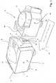
- the device arrangement shown comprises a CPAP device generally designated by the reference numeral 1 and a moistening device 2 connected thereto in modular fashion.
- the CPAP device 1 here has a substantially block-shaped or box-shaped housing 3 which has a front end face 4, two opposite one another in pairs and mutually substantially parallel side surfaces 5, 6 and a relative to the front end face 4 in the rear region of the housing 3 arranged rear 7 and an upper top surface 8, in the region of the front end face 4, a connecting device 9 is provided which in the illustrated here Embodiment a breathing gas connection piece 10, a Druckmeßschlauchanschlußstutzen 11 and an electrical connection device 12 has.
- the breathing gas connection piece 10 and the Druckmeßschlauchanschlußstutzen 11 are arranged in a recess 13 shown here only hinted substantially completely sunk.
- the contact elements of an electrical connection device 12 are received in a recess, so that these connecting members also not or not substantially survive over a defined by the front face 4 surface.
- the front end face 4 is formed slightly arched, resulting in a particularly effective support the centering of the moistening device 2.
- the breathing gas connection piece 10 and the Druckmeßschlauchanschlußstutzen 11 are aligned such that they extend substantially parallel to the direction indicated by the arrow 14 joining direction.
- the CPAP device 1 has in its bottom area Uberstellorgane (here adjustable feet 15), which are designed such that the connecting members of the connecting device 9 are held at a predetermined vertical height level, which is exactly matched to the corresponding height level of the connecting members of the moistening device 2.
- Aufstellorgane here adjustable feet 15
- the moistening device 2 comprises a base body 16 and a liquid reservoir 17 accommodated therein.
- the fluid reservoir 17 can be removed from the base housing 16, for example, for adding moistening fluid.
- the base housing has a correspondingly complementary to the front end face 4 of the CPAP device 1 formed pad portion 18, in which the below still with reference to Fig. 2 located in detail explained connecting organs.
- the base housing 16 is in turn provided with connecting members, which correspond in their construction and in their arrangement substantially the already described with respect.
- the CPAP device 1 connecting device 9. This makes it possible to connect the provided for example for connection to the CPAP device 1 hose connector directly to the moistening device 2. In this case, a connection of the Druckmeßschlauches is achieved simultaneously.
- the moistening device 2 also has adjustable feet 20, through which the part of the moistening device in the region of the pad portion 18 provided Connection are held at a vertical height level, which corresponds to the height level of the connecting device 9.
- connection device 9 is complementary to the provided by the moistening device 2 connecting device 21 is formed.
- the two connection devices 9 and 21, as shown by the arrow 22, can be brought together in Füwolf.
- a particularly effective pre-positioning of the connecting members, in particular the breathing gas connection piece 10 and the corresponding counterpart 23 is achieved in this embodiment in that the counterpart 23 is also centered by the inner wall 24 of the recess 13.
- the breathing gas connection piece 10 and provided by the moistening device 2 counterpart 23 are at exactly the same vertical height level.
- a connection structure is provided which corresponds in its essential dimensions to the connection structure provided on the side of the CPAP device.
- the breathing tube connector 25 shown here can thus be coupled, if necessary, directly to the CPAP device 1 or to the moistening device 2. Due to an integrated into the humidifier Druckmeßharms ein is even when the breathing tube connector 25 is connected to the humidifier 2, a connection between the Druckmeßschlauch 26 and the Druckmeßschlauchanschlußstutzen 11 given.
- CPAP device arrangement may be used as described in the following application example.
- the moistening device according to the invention also placed on the table surface and attached along a table surface parallel to the front face of the CPAP device 1 substantially perpendicular joining direction on the CPAP device.
- connection devices 9 and 21 provided on the part of the CPAP device 1 and part of the moistening device 2 connection devices 9 and 21 in joining position.
- electrical connection device 12 is also a power supply provided by the moistening device 2 heating device.
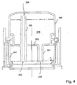
- the representation acc. Fig. 3 shows a longitudinal sectional view through a device for humidifying a breathing gas (hereinafter referred to as moistening device) acc. a preferred embodiment of the invention.
- moistening device a device for humidifying a breathing gas
- the embodiment of the moistening device shown here comprises a refilling unit 203 formed from a tub element 1 and a pot part 202 coupled thereto, which can be removed in a simple manner from a set-up housing 204 which is designed in several parts.
- the tub member 201 and the pot member 202 are coupled to each other in a sealing manner.
- the coupling of tub element 201 and cup part 202 takes place via a sealing structure 206, which has a first sealing ring 207 and a second sealing ring 208 in the embodiment shown here.
- the two sealing rings 207 and 208 are received in circumferential grooves, which are formed in a separating element 209.
- the separating element 209 has an here formed integrally partition wall 205.
- the partition wall 205 separates the inner portion of the cup portion 202 from the inner portion of the tub member 201.
- a liquid reservoir 10 is formed in connection with the partition wall 205, in which initially the majority of the liquid provided for moistening the respiratory gas is stored.
- a separate moistening region is formed in which only a subset of the moistening liquid is received.
- the level a, the liquid received in the tub member 201 is maintained at a predetermined level by a metering device.
- fluid is supplied successively or continuously from the fluid reservoir 210.
- a preferred embodiment of a metering device provided for this purpose is used in conjunction with Fig. 2 will be described in detail.
- the tub member 201 is here formed substantially cup-like and has a Atemgaszutrittsö réelle 211 and a breathing gas outlet opening 212.
- a CPAP device Via the breathing gas inlet opening 211, according to the breathing activity of a patient, the respiratory gas conveyed by a CPAP device, not shown here, can flow into the tub element 201.
- a deflecting device 213 By means of a deflecting device 213, which is shown here only in a simplified manner, the inflowing respiratory gas is conducted onto the liquid present in the tub element 201. In this case, the supplied breathing gas accumulates with moisture. The correspondingly humidified breathing gas can then flow out via the respiratory gas outlet opening 212.
- the tub element 201 can be heated by means of a heating device 214 in the embodiment shown here.
- the heater 214 is composed of a heating element disposed in the erecting housing 204 so that the bottom portion of the tub member 201 can be intimately contacted therewith.
- the bottom region 215 of the heating element 201 is formed from a material of high thermal conductivity, for example metal. In the latter embodiment, said bottom portion 215 may, for example, in the insert molding process in the actual main body of the tub member 201 be formed.
- the tub member 201 is formed such that it can be used self-positioning in light fitting in the erection housing 204. In this case, the breathing gas inlet opening 211 and the respiratory gas outlet opening are aligned with correspondingly complementary openings or lines formed in the erection housing 204.
- the erection housing 4 is provided with a connecting piece 216 which, in the embodiment shown here, can be attached directly to a correspondingly complementary connecting section of a CPAP device.
- a further connection piece 217 is provided, which can be coupled to a provided on the part of a CPAP device pressure detection terminal.
- the connecting piece 217 forms part of a line system, which is ultimately connected to the provided on an opposite side of the moistening pressure measuring connection piece 218 in connection.
- a pressure measuring hose can be connected to this pressure measuring connection 218 for detecting the pressure in the region of the breathing hose, a gas exchange valve or possibly also directly in the mask area.
- the erection housing 204 is provided with a breathing tube connection piece 219.
- the hose connection members formed on the output side of the humidification device are identical to those of a CPAP device in that corresponding connection hoses can either be connected directly to the CPAP device or, if necessary, when using the humidifying device only to the output side of the humidification device 202
- Reference numeral 16 marked connecting piece is provided a connector means not shown here, via which an electrical connection between the heater 214 and provided on the part of the CPAP device power supply device can be produced. Possibly. It is also possible to transmit electrical signals, for example pressure measuring signals, via this plug connection device.
- the erection housing 204 is further provided with a fastening device 220, via which the moistening device can be mechanically comparatively rigidly coupled to a CPAP device.
- a metering device for metering the amount of fluid in the tub element 201 will be described.
- the liquid front room 210 and the humidification area formed in the tub member 201 are separated from each other via the partition wall 205. If necessary, the fluid stored in the liquid storage space 210 can be transferred to the humidification area via a fluid line device.
- the control of the fluid Vietnamesestromes takes place here by controlling the Luftnachschreib in the liquid reservoir.
- the regulation of the air feed takes place via a metering line device 222, which, similar to the aforementioned fluid line device 221, passes vertically through the dividing wall 205.
- the dosing line device 222 has a first orifice 223 and a second orifice 224.
- the first orifice 223 is disposed at the level of the target level a. As long as the first orifice 223 is closed by the fluid contained in the tub element 201, no air can flow into the liquid storage space 210, so that again no fluid can flow out of the liquid storage space 210 via the fluid conduit device 221. As soon as the level a drops below the level of the first orifice, air can flow into the liquid reservoir, which in turn allows fluid to pass from the liquid reservoir 210 into the well element 201 or the separate humidification area formed therein.
- the fluid conduit device 221 has an exit orifice 225, which lies slightly below the nominal level indicated here by the letters a.
- the fluid conduit device 221, the dosing line device 222 and the partition wall 5 are formed in the embodiment shown here by an integral part.
- the cup part 202 can also be provided with a corresponding, sealingly closable refill opening.
- the cup portion 202, the dividing wall integral part and the tub member may each be cleaned separately.
- the dosing line device 222 is such designed such that the second orifice 224 provided thereon is above the maximum fill level of the liquid storage space 210.
- Fig. 5 is the preceding in connection with the Fig. 3 and 4 described moistening device shown in perspective.
- the pot part which is preferably formed from a transparent material, can be seen here as a cup which is essentially cylindrical. This cup is inserted in a likewise cylindrical, formed in the erection housing 204 receiving portion. In the area of the cup part 202, the erection housing 204 is designed such that the cup part can be grasped with one hand.
- Fig. 3 described connecting piece 217 or Druckmeßanschlußstutzen 218 provided. Below the said connection piece is the in Fig.
- the back side 226 of the moistening device is corresponding to the front of one below in connection with Fig. 6a trained CPAP device so that the moistening device can be connected to the modular CPAP device with virtually no gap.
- CPAP device has a substantially cuboid housing in the upper region of a handle device 230 is provided via which the CPAP device can be taken in an ergonomically advantageous manner.
- a front end face connecting members 231 are provided for connecting at least one breathing tube.
- a breathing tube fitting pin 32 and a pressure measuring tube fitting pin 233 are provided.
- the arrangement of these connecting members substantially corresponds to the arrangement of in connection with Figure 3 connecting members 216 and 217.
- the connecting members 231 are further formed such that the part of the moistening device ( Figure 3 ) provided connecting members 216, 217 directly on or can be plugged.
- In the bottom region of the CPAP device further engagement structures are provided which are engageable with complementarily formed engaging portions of the moistening device in engagement.
- the connecting members 231 are here sunk in such a way that they do not project beyond an outer insbesonder front surface of the housing.
- Fig. 6b is the preceding in connection with the Figures 3 . 4 and 5 described moistening device with a view of the front area shown.
- the connecting pieces 216 and 217 are similar to the side of the CPAP device sunk.
- the connecting pieces are surrounded by a plug receiving space 34 in which a preferably formed of a soft material, in particular silicone rubber plug can be inserted.
- the plug receiving space 234 is preferably formed such that a corresponding plug slides on both the respective pin 216, 217 and along the wall of the plug receiving space 234.
- the invention is not limited to the embodiments described above.
- refill units which in the structure and the moistening principle deviate from the described moistening device.
- the tub element of the moistening unit in such a way that it can be connected directly to the CPAP device while dispensing with the positioning housing.
- the moistening device described can also be connected with the interposition of a hose with a source of breathing gas.
- the refill unit can also be arranged as a substantially trough-like unit under the CPAP device.
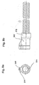
- connection device 302 which here comprises a base body 303 formed of an elastomeric material esp. Silicone rubber with two molded coupling portions 304,305.
- the two coupling sections 304, 305 are integrally formed by mutually parallel and circular in cross section tube zones.
- the inner diameter of the respective tube zone is slightly smaller than the outer diameter of the connecting pin entering the two tube zones when the plug is connected and slightly widened.
- a fastening section 306 is formed, in which the breathing hose 301 is fixed via a ring element 307.
- the ring member 307 is also formed here of an elastomeric material and bonded to the outer surface of the breathing tube.
- the Druckmeßschlauch 308 opens via a formed in the base body 2 through-channel 309 in the coupling portion 305.
- the Druckmeßschlauch 308 is glued or vulcanized into the base body 302.
- the passageway 309 is formed so that the Druckmeßschlauch 308 is only slightly curved.
- the angle a between the longitudinal center axis of the coupling portion 304 and the longitudinal center axis of the feedthrough channel 309 is preferably less than 35 °.
- the respiratory gas conduit region 311 formed in the base body 303 also passes essentially continuously into the interior region of the breathing tube 301.
- hoses 301, 308 With appropriate elasticity of the hoses 301, 308, it is possible to guide them to the end face 312 of the base body 303, so that the device-side coupling members can enter directly into the hoses 301, 308.
- FIGS. 8a and 8b Based on FIGS. 8a and 8b the outer shape of the base body gem.
- an effective pre-positioning of the base body is achieved in a recess provided on the device side.
- This nose-like radially projecting region drops continuously from the breathing tube-side end of the base body 303.
- a peripheral bead 315 is provided, via which a force flow, which is favorable under mechanical aspects, between hose and plug structure is achieved.
- a preferred embodiment of a device-side connection structure is shown, which is formed substantially complementary to the coupling sections 304, 305 formed in the base body 303 of the plug.
- the spigot portion indicated here by the reference numeral 316 passes in joining position into the coupling portion 304.
- the spigot portion indicated by the reference numeral 317 engages in the joining position with the coupling portion.
- the two journal sections 316, 317 are recessed in a recess 318.
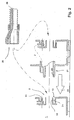
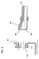
- This in Figure 10 shown terminal structure component comprises a breathing gas passage means, which is designed here as a tubular pin 401.
- This tube pin 401 leaving a gap between a further tube pin 402 adjacent.
- This pipe plug 402 forms a Druckmeßschlauchanschluß issued.
- Both tube pins 401, 402 are recessed in a recess 403. This recess is surrounded by a front cover plate 404.
- the cover plate 4 and those the recess 403 bounding wall are integrally formed.
- a base plate 405 which here forms a cover plate for a labyrinth arrangement.
- This labyrinth arrangement not described in detail here, forms an extended breathing gas guide path for absorbing any noise generated by a blower device.
- the base plate 405 is insbes. Foam coated on the rear side not visible here with a sound-absorbing material.
- connection channel 406 is formed, via which the inner region of the pipe pin 402 can be coupled to a pressure converter arranged on a control board.
- the terminal structure component is further provided with fastening means 407, 408 via which this component is fixable in a CPAP device in a simple exchangeable manner.
- 11A shows here a ergonomically favorable handle compact connector with integrated Druckmeßschlauch be operation.
- Terminal structure component can be connected to a corresponding CPAP device.
- Fig. 11c shows a simplified simplified coupling portion of a humidifier, which can be attached directly to the structure of the invention to a CPAP device.
- the pin identified by the reference numeral 411 engages with the pipe spigot 401 and the bore portion 412 engages with the pipe spigot 402.
Claims (18)
- Appareil (1) pour le refoulement d'un gaz respirable sous pression positive, comprenant:- un dispositif de soufflante pour le refoulement du gaz respirable,- un dispositif de boîtier (3) avec une partie de base,- une partie de surface supérieure (8) et une partie latérale s'étendant vers le haut entre la partie de surface supérieure (8) et la partie de base, et un dispositif de connexion (9) pour le branchement direct d'un dispositif d'humidification (2) pour l'humidification du gaz respirable, le dispositif de connexion (9) étant disposé dans la partie latérale de l'appareil (1) de telle manière que le dispositif d'humidification (2) peut être accouplé latéralement, permettant ainsi de positionner l'appareil (1) et le dispositif d'humidification (2) sur un support sensiblement plan et de placer le dispositif d'humidification (2) en position d'accouplement à côté de l'appareil (1) pour le refoulement d'un gaz respirable sous pression positive.
- Appareil (1) selon la revendication 1, caractérisé en ce qu'un dispositif de verrouillage est prévu pour le maintien du dispositif d'humidification (2) en position d'assemblage.
- Appareil (1) selon la revendication 2, où le dispositif de verrouillage permet en outre de débrancher manuellement le dispositif d'humidification (2) du dispositif de connexion (9).
- Appareil (1) selon au moins une des revendications précédentes, caractérisé en ce qu'un élément de support (15) est prévu, monté de telle manière que le dispositif de connexion (9) est maintenu à un niveau de hauteur correspondant au niveau vertical des éléments de connexion (21) prévus sur le dispositif d'humidification (2).
- Appareil (1) selon une des revendications précédentes, caractérisé en ce que le dispositif de connexion (9) est orienté sensiblement suivant une direction d'assemblage (14).
- Appareil (1) selon au moins une des revendications précédentes, caractérisé en ce que le dispositif de connexion (9) comporte des éléments de connexion et en ce qu'au moins un des éléments de connexion est formé par une section de connexion (10).
- Appareil (1) selon au moins une des revendications précédentes, caractérisé en ce qu'une zone de surface de la partie latérale présente une configuration sensiblement complémentaire à celle d'une zone du dispositif d'humidification (2) contiguë en position d'assemblage.
- Appareil (1) selon au moins une des revendications précédentes, où des structures d'enclenchement sont prévues dans la partie de base, lesquelles peuvent être mises en contact avec des parties d'enclenchement configurées de manière complémentaire du dispositif d'humidification (2).
- Appareil (1) selon au moins une des revendications précédentes, caractérisé en ce que le dispositif de connexion (9) comprend la section de connexion (10) pour la conduite du gaz respirable et une section de conduite (11) pour l'accouplement d'une conduite de mesure de pression.
- Appareil (1) selon la revendication 8 avec les caractéristiques de la revendication 6, caractérisé en ce que la section de connexion (10) et la section de conduite (11) sont disposées de manière contiguë l'une à l'autre.
- Appareil (1) selon au moins une des revendications précédentes, caractérisé en ce que les deux sections de connexion (10) sont disposées dans une ouverture (13).
- Appareil (1) selon au moins une des revendications précédentes, caractérisé en ce que le dispositif de connexion (9) ne dépasse sensiblement pas d'une surface définie par la partie latérale (4) de l'appareil (1).
- Appareil (1) selon au moins une des revendications précédentes, caractérisé en ce que le dispositif de connexion (9) comporte en outre des éléments de connexion électrique (12) pour réaliser une liaison électrique au dispositif d'humidification (2).
- Appareil (1) selon la revendication 13, caractérisé en ce que les éléments de connexion électrique (12) sont prévus pour la transmission de signaux électriques, en particulier pour l'alimentation en tension du dispositif d'humidification (2) et/ou pour la transmission d'un signal de niveau de remplissage.
- Appareil (1) selon au moins une des revendications précédentes, caractérisé en ce que des aides au centrage sont prévues, la paroi intérieure de l'ouverture recevant la section de connexion (10) étant préférentiellement ajustée à la surface périphérique extérieure de la broche de connexion (216) prévue sur le dispositif d'humidification (2).
- Dispositif d'humidification (2) pour un appareil (1) pour le refoulement d'un gaz respirable sous pression positive, avec un boîtier de base (16) et un réservoir (17) pour le stockage de l'eau d'humidification à raccorder à un appareil (1) pour le refoulement d'un gaz respirable sous pression positive, en particulier selon l'une des revendications 1 à 15, caractérisé en ce que le dispositif d'humidification (2) comprend un dispositif de connexion (21) permettant un branchement direct à un dispositif de connexion (9) prévu dans la partie latérale d'un appareil (1) pour le refoulement d'un gaz respirable sous pression positive, de telle manière que le dispositif d'humidification (2) se trouve en position d'accouplement à côté de l'appareil (1) pour le refoulement d'un gaz respirable sous pression positive, le dispositif d'humidification (2) étant prévu pour être accouplé à l'appareil (1) pour le refoulement d'un gaz respirable sous pression positive, de telle manière que l'appareil (1) pour le refoulement d'un gaz respirable sous pression positive et le dispositif d'humidification (2) sont positionnés sur un support sensiblement plan.
- Dispositif d'humidification (2) selon la revendication 16, caractérisé en ce que le dispositif de connexion (21) du dispositif d'humidification est configuré de manière complémentaire au dispositif de connexion (9) prévu sur le côté de l'appareil (1) pour le refoulement d'un gaz respirable sous pression positive.
- Dispositif d'humidification (2) selon la revendication 16 ou la revendication 17, comprenant en outre un boîtier de montage (204) et un dispositif de fixation (220) pour l'accouplement mécanique du dispositif d'humidification (2) à l'appareil (1) pour le refoulement d'un gaz respirable sous pression positive.
Applications Claiming Priority (6)
| Application Number | Priority Date | Filing Date | Title |
|---|---|---|---|
| DE19936499A DE19936499A1 (de) | 1999-08-05 | 1999-08-05 | Vorrichtung zur Atemgasbefeuchtung sowie hierfür vorgesehenes CPAP-Gerät |
| DE1999149283 DE19949283C2 (de) | 1999-10-13 | 1999-10-13 | Atemschlauch-Anschlussvorrichtung sowie hiermit versehener Atemschlauch |
| DE1999149292 DE19949292A1 (de) | 1999-10-13 | 1999-10-13 | Vorrichtung zur Zufuhr eines Atemgases unter Überdruck und hierfür vorgesehene Befeuchtungsvorrichtung |
| DE29918048U DE29918048U1 (de) | 1999-10-13 | 1999-10-13 | Anschlußstrukturbauteil für einen Atemschlauch |
| EP00953159A EP1210139B1 (fr) | 1999-08-05 | 2000-08-04 | Dispositif d'alimentation en gaz respiratoire et dispositif d'humidification |
| EP06006804.6A EP1669098B1 (fr) | 1999-08-05 | 2000-08-04 | Dispositif pour délivrer un gaz respiratoire, humidificateur, tube respiratoire, et dispositif de connection |
Related Parent Applications (5)
| Application Number | Title | Priority Date | Filing Date |
|---|---|---|---|
| EP00953159.1 Division | 2000-08-04 | ||
| EP06006804.6A Division-Into EP1669098B1 (fr) | 1999-08-05 | 2000-08-04 | Dispositif pour délivrer un gaz respiratoire, humidificateur, tube respiratoire, et dispositif de connection |
| EP06006804.6A Division EP1669098B1 (fr) | 1999-08-05 | 2000-08-04 | Dispositif pour délivrer un gaz respiratoire, humidificateur, tube respiratoire, et dispositif de connection |
| EP00953159A Division EP1210139B1 (fr) | 1999-08-05 | 2000-08-04 | Dispositif d'alimentation en gaz respiratoire et dispositif d'humidification |
| EP06006804.6 Division | 2006-03-30 |
Publications (3)
| Publication Number | Publication Date |
|---|---|
| EP2308539A2 EP2308539A2 (fr) | 2011-04-13 |
| EP2308539A3 EP2308539A3 (fr) | 2013-01-16 |
| EP2308539B1 true EP2308539B1 (fr) | 2016-04-20 |
Family
ID=27438973
Family Applications (4)
| Application Number | Title | Priority Date | Filing Date |
|---|---|---|---|
| EP10185455.2A Expired - Lifetime EP2308539B1 (fr) | 1999-08-05 | 2000-08-04 | Dispositif pour délivrer un gaz respiratoire, humidificateur, tube respiratoire, et dispositif de connection |
| EP00953159A Expired - Lifetime EP1210139B1 (fr) | 1999-08-05 | 2000-08-04 | Dispositif d'alimentation en gaz respiratoire et dispositif d'humidification |
| EP10185462.8A Expired - Lifetime EP2345449B1 (fr) | 1999-08-05 | 2000-08-04 | Tube respiratoire, dispositif de connection et sa structure |
| EP06006804.6A Expired - Lifetime EP1669098B1 (fr) | 1999-08-05 | 2000-08-04 | Dispositif pour délivrer un gaz respiratoire, humidificateur, tube respiratoire, et dispositif de connection |
Family Applications After (3)
| Application Number | Title | Priority Date | Filing Date |
|---|---|---|---|
| EP00953159A Expired - Lifetime EP1210139B1 (fr) | 1999-08-05 | 2000-08-04 | Dispositif d'alimentation en gaz respiratoire et dispositif d'humidification |
| EP10185462.8A Expired - Lifetime EP2345449B1 (fr) | 1999-08-05 | 2000-08-04 | Tube respiratoire, dispositif de connection et sa structure |
| EP06006804.6A Expired - Lifetime EP1669098B1 (fr) | 1999-08-05 | 2000-08-04 | Dispositif pour délivrer un gaz respiratoire, humidificateur, tube respiratoire, et dispositif de connection |
Country Status (8)
| Country | Link |
|---|---|
| US (11) | US7096864B1 (fr) |
| EP (4) | EP2308539B1 (fr) |
| JP (1) | JP4695318B2 (fr) |
| AT (1) | ATE342084T1 (fr) |
| AU (1) | AU6570600A (fr) |
| DE (3) | DE10082260B4 (fr) |
| ES (1) | ES2574232T3 (fr) |
| WO (1) | WO2001010489A2 (fr) |
Families Citing this family (158)
| Publication number | Priority date | Publication date | Assignee | Title |
|---|---|---|---|---|
| JP4695318B2 (ja) * | 1999-08-05 | 2011-06-08 | エムアーペー メディツィンテクノロジー ゲゼルシャフト・ミット・ベシュレンクテル・ハフツング | 呼気ガスを供給する装置、加湿装置、呼吸用チューブ接続デバイス、呼吸用チューブ及び接続構造 |
| US7588029B2 (en) | 2000-03-21 | 2009-09-15 | Fisher & Paykel Healthcare Limited | Humidified gases delivery apparatus |
| US7111624B2 (en) | 2000-03-21 | 2006-09-26 | Fisher & Paykel Healthcare Limited | Apparatus for delivering humidified gases |
| US6918389B2 (en) | 2000-03-21 | 2005-07-19 | Fisher & Paykel Healthcare Limited | Breathing assistance apparatus |
| US7120354B2 (en) | 2000-03-21 | 2006-10-10 | Fisher & Paykel Healthcare Limited | Gases delivery conduit |
| JP4180367B2 (ja) | 2000-10-16 | 2008-11-12 | フィッシャー アンド ペイケル ヘルスケア リミテッド | 医療処置でガスの加湿に使用する装置 |
| US6571794B1 (en) * | 2000-10-19 | 2003-06-03 | Mallinckrodt, Inc. | Multi-lumen hose for respirators |
| AU2002231456B2 (en) * | 2001-02-16 | 2007-05-24 | ResMed Pty Ltd | Air pressure signal monitoring in apparatus for treating sleep disordered breathing |
| US6935337B2 (en) * | 2001-02-16 | 2005-08-30 | Resmed Limited | Humidifier with structure to prevent backflow of liquid through the humidifier inlet |
| NZ527089A (en) | 2001-02-16 | 2005-09-30 | Resmed Ltd | Air pressure signal monitoring in apparatus for treating sleep disordered breathing |
| DE10139881B4 (de) * | 2001-08-20 | 2017-06-08 | Resmed R&D Germany Gmbh | Vorrichtung zur Zufuhr eines Atemgases und Verfahren zur Steuerung derselben |
| ATE473774T1 (de) | 2001-10-22 | 2010-07-15 | Map Medizin Technologie Gmbh | Medizinische maske |
| DE19212475T1 (de) * | 2002-09-17 | 2020-05-28 | Fisher & Paykel Healthcare Limited | Gerät zur abgabe von befeuchteten gasen |
| DK2116271T3 (en) * | 2002-11-12 | 2016-07-25 | Fisher & Paykel Healthcare Ltd | Apparatus for breathing assistance |
| EP1575650B1 (fr) | 2002-12-06 | 2016-05-25 | Fisher & Paykel Healthcare Limited | Embout buccal |
| DE10310462B4 (de) * | 2003-03-11 | 2017-01-05 | Löwenstein Medical Technology S.A. | Vorrichtung zur Beatmung |
| DE10322431B4 (de) * | 2003-05-19 | 2021-07-01 | Löwenstein Medical Technology S.A. | Verfahren zur Zufuhr von Atemgas sowie Vorrichtung zur Beatmung |
| AU2003903139A0 (en) | 2003-06-20 | 2003-07-03 | Resmed Limited | Breathable gas apparatus with humidifier |
| NZ585683A (en) | 2003-06-20 | 2011-12-22 | Resmed Ltd | Breathable gas apparatus with humidifier |
| JP4986620B2 (ja) * | 2003-08-01 | 2012-07-25 | フィッシャー アンド ペイケル ヘルスケア リミテッド | 一体式加湿器を備えた呼吸ガスの供給装置 |
| DK1656173T3 (en) | 2003-08-20 | 2016-04-11 | Fisher & Paykel Healthcare Ltd | Humidifier water chamber |
| CN1901960A (zh) * | 2003-11-05 | 2007-01-24 | Map医药-技术有限责任公司 | 供给呼吸气体的装置和设在所述装置中的空气输送结构 |
| US7350519B2 (en) * | 2003-12-29 | 2008-04-01 | Timothy Alan Duncan | Method and apparatus for delivering an additive with a CPAP machine |
| DE102005063661B3 (de) * | 2004-02-20 | 2023-08-17 | Löwenstein Medical Technology S.A. | Modulare Vorrichtung zur Befeuchtung von Atemgas |
| WO2005079726A1 (fr) | 2004-02-23 | 2005-09-01 | Fisher & Paykel Healthcare Limited | Appareil d'assistance respiratoire |
| EP1737524B1 (fr) | 2004-04-02 | 2018-10-10 | Fisher & Paykel Healthcare Limited | Appareil d'assistance a la respiration |
| US9072852B2 (en) | 2004-04-02 | 2015-07-07 | Fisher & Paykel Healthcare Limited | Breathing assistance apparatus |
| EP4049703B1 (fr) | 2004-08-20 | 2023-09-27 | Fisher & Paykel Healthcare Limited | Appareil de mesure des propriétés des gaz administrés à un patient |
| FR2875138B1 (fr) | 2004-09-15 | 2008-07-11 | Mallinckrodt Dev France Sa | Procede de regulation pour un humidificateur chauffant |
| DE102006034028A1 (de) * | 2005-08-01 | 2007-02-08 | Weinmann Geräte für Medizin GmbH + Co. KG | Vorrichtung zur Beatmung |
| US8739780B2 (en) | 2005-08-15 | 2014-06-03 | Resmed Limited | Low cost CPAP flow generator and humidifier assembly |
| US7677246B2 (en) * | 2005-09-23 | 2010-03-16 | Ric Investments, Llc | Modular pressure support system |
| US8074645B2 (en) * | 2006-04-10 | 2011-12-13 | Somnetics Global Pte. Ltd. | Apparatus and methods for providing humidity in respiratory therapy |
| CN101466429A (zh) | 2006-04-10 | 2009-06-24 | 艾伊欧麦德有限公司 | 用于进行气道正压治疗的设备和方法 |
| WO2007149446A2 (fr) * | 2006-06-16 | 2007-12-27 | Aeiomed, Inc. | Appareil modulaire de thérapie de pression positive des voies aériennes et procédés |
| CN102631741B (zh) | 2006-07-14 | 2015-11-04 | 菲舍尔和佩克尔保健有限公司 | 呼吸辅助装置 |
| DE102006044091A1 (de) * | 2006-09-20 | 2008-04-03 | Carl Zeiss Microimaging Gmbh | Steuermodul und Steuersystem zur Beeinflussung von Probenumgebungsparametern eines Inkubationssystems, Verfahren zur Steuerung einer Mikroskopanordnung und Computerprogrammprodukt |
| DE102006045739B3 (de) * | 2006-09-27 | 2007-08-30 | Dräger Medical AG & Co. KG | Vorrichtung mit einem Beatmungsgerät und einem Anfeuchter |
| CA2881603C (fr) | 2006-11-06 | 2017-04-18 | Fisher & Paykel Healthcare Limited | Chambre et couvercle d'humidificateur integres |
| US20080221930A1 (en) | 2007-03-09 | 2008-09-11 | Spacelabs Medical, Inc. | Health data collection tool |
| JP5468747B2 (ja) | 2007-06-05 | 2014-04-09 | レスメド・モーター・テクノロジーズ・インコーポレーテッド | 軸受管を有するブロワ |
| US8365726B2 (en) * | 2007-06-07 | 2013-02-05 | Resmed Limited | Tub for humidifier |
| US8550075B2 (en) * | 2007-06-28 | 2013-10-08 | Resmed Limited | Removable and/or replaceable humidifier |
| US8677993B2 (en) * | 2007-07-18 | 2014-03-25 | Vapotherm, Inc. | Humidifier for breathing gas heating and humidification system |
| USD798437S1 (en) | 2007-07-30 | 2017-09-26 | Fisher & Paykel Healthcare Limited | Breathing apparatus |
| US8905023B2 (en) | 2007-10-05 | 2014-12-09 | Vapotherm, Inc. | Hyperthermic humidification system |
| EP2200687B1 (fr) * | 2007-10-05 | 2015-06-17 | Vapotherm, Inc. | Système d'humidification hyperthermique |
| US9802022B2 (en) | 2008-03-06 | 2017-10-31 | Resmed Limited | Humidification of respiratory gases |
| US9505164B2 (en) | 2009-12-30 | 2016-11-29 | Schauenburg Technology Se | Tapered helically reinforced hose and its manufacture |
| DE102008022663B4 (de) | 2008-05-07 | 2012-10-31 | Schauenburg Hose Technology Gmbh | Stretch-Schlauch |
| US10258757B2 (en) | 2008-05-12 | 2019-04-16 | Fisher & Paykel Healthcare Limited | Patient interface and aspects thereof |
| US10792451B2 (en) | 2008-05-12 | 2020-10-06 | Fisher & Paykel Healthcare Limited | Patient interface and aspects thereof |
| NZ742900A (en) | 2008-06-05 | 2020-02-28 | ResMed Pty Ltd | Treatment of respiratory conditions by automatic control of flow and/or temperature and/or humidity independently to nares via separate flow paths |
| US11660413B2 (en) | 2008-07-18 | 2023-05-30 | Fisher & Paykel Healthcare Limited | Breathing assistance apparatus |
| CN109481813B (zh) | 2008-09-17 | 2022-01-11 | 瑞思迈私人有限公司 | 用于插入到加湿器腔室中的箱和加湿器 |
| EP2349428B1 (fr) | 2008-10-10 | 2017-09-20 | Fisher & Paykel Healthcare Limited | Embouts nasaux pour une interface patient |
| US8453640B2 (en) | 2008-11-12 | 2013-06-04 | Resmed Limited | Positive airway pressure device |
| US8517017B2 (en) * | 2009-01-08 | 2013-08-27 | Hancock Medical, Inc. | Self-contained, intermittent positive airway pressure systems and methods for treating sleep apnea, snoring, and other respiratory disorders |
| US9964238B2 (en) | 2009-01-15 | 2018-05-08 | Globalmed, Inc. | Stretch hose and hose production method |
| CN102316920B (zh) | 2009-02-13 | 2015-09-16 | 皇家飞利浦电子股份有限公司 | 压力支持设备用户界面 |
| US20100242961A1 (en) * | 2009-03-31 | 2010-09-30 | Nellcor Puritan Bennett Llc | Systems and methods for preventing water damage in a breathing assistance system |
| US20100300446A1 (en) * | 2009-05-26 | 2010-12-02 | Nellcor Puritan Bennett Llc | Systems and methods for protecting components of a breathing assistance system |
| US8931481B2 (en) | 2009-06-04 | 2015-01-13 | Redmed Limited | Flow generator chassis assembly with suspension seal |
| US9174017B2 (en) * | 2009-06-05 | 2015-11-03 | Fisher & Paykel Healthcare Limited | Humidifier heater base |
| AU2010206053B2 (en) | 2009-07-31 | 2014-08-07 | ResMed Pty Ltd | Wire Heated Tube with Temperature Control System, Tube Type Detection, and Active Over Temperature Protection for Humidifier for Respiratory Apparatus |
| US9604020B2 (en) | 2009-10-16 | 2017-03-28 | Spacelabs Healthcare Llc | Integrated, extendable anesthesia system |
| IN2012DN03108A (fr) | 2009-10-16 | 2015-09-18 | Spacelabs Healthcare Llc | |
| EP2501423A4 (fr) | 2009-11-18 | 2014-10-29 | Fisher & Paykel Healthcare Ltd | Interface nasale |
| EP3912666A1 (fr) | 2009-12-23 | 2021-11-24 | Fisher & Paykel Healthcare Limited | Interface patient et un casque |
| CN102711892B (zh) | 2009-12-28 | 2015-05-06 | 皇家飞利浦电子股份有限公司 | 压力支持系统中的湿度控制 |
| AU2010342297B2 (en) * | 2010-01-15 | 2014-09-11 | Koninklijke Philips Electronics N.V. | Humidification system with signal transmission optimization |
| EP3503115A3 (fr) | 2010-03-21 | 2019-10-23 | Spacelabs Healthcare LLC | Système de surveillance de patients |
| WO2012047121A1 (fr) | 2010-10-08 | 2012-04-12 | Fisher & Paykel Healthcare Limited | Appareil d'assistance respiratoire |
| BR112013012329B1 (pt) | 2010-11-19 | 2021-05-04 | Spacelabs Healthcare, Llc | Dispositivo de tela para uso em um sistema de monitoramento de paciente e sistema de monitoramento de paciente |
| WO2012128808A2 (fr) * | 2010-12-17 | 2012-09-27 | Spacelabs Healthcare, Llc | Système d'anesthésie extensible intégré |
| US8327846B2 (en) | 2011-02-08 | 2012-12-11 | Hancock Medical, Inc. | Positive airway pressure system with head position control |
| US9629566B2 (en) | 2011-03-11 | 2017-04-25 | Spacelabs Healthcare Llc | Methods and systems to determine multi-parameter managed alarm hierarchy during patient monitoring |
| US10603456B2 (en) | 2011-04-15 | 2020-03-31 | Fisher & Paykel Healthcare Limited | Interface comprising a nasal sealing portion |
| EP4282456A3 (fr) | 2011-04-15 | 2024-02-14 | Fisher & Paykel Healthcare Limited | Interface comprenant une partie de pont nasal roulante |
| EP3586898B1 (fr) | 2011-05-06 | 2024-03-20 | Fisher & Paykel Healthcare Limited | Composant pour un circuit médical |
| US10080866B2 (en) | 2011-06-03 | 2018-09-25 | Fisher & Paykel Healthcare Limited | Medical tubes and methods of manufacture |
| EP3470104B1 (fr) | 2011-07-13 | 2023-01-25 | Fisher & Paykel Healthcare Limited | Ensemble rotor et moteur |
| ITRE20110054A1 (it) * | 2011-07-19 | 2013-01-20 | Starmed S P A | Casco apribile per la ventilazione non invasiva di pazienti |
| US9649459B2 (en) * | 2011-09-26 | 2017-05-16 | Resmed Paris Sas | Ventilator apparatus and method |
| US10213573B2 (en) | 2011-12-22 | 2019-02-26 | Resmed Limited | Humidifiers for respiratory apparatus |
| WO2013137753A1 (fr) | 2012-03-15 | 2013-09-19 | Fisher & Paykel Healthcare Limited | Système d'humidification de gaz respiratoire |
| GB2577634B (en) * | 2012-04-27 | 2020-09-30 | Fisher & Paykel Healthcare Ltd | Respiratory humidification apparatus |
| CN107626023B (zh) | 2012-08-08 | 2021-03-02 | 费雪派克医疗保健有限公司 | 在提供呼吸治疗中使用的接口组件 |
| EP4279106A3 (fr) | 2012-09-04 | 2024-01-17 | Fisher & Paykel Healthcare Limited | Masque de valsalva |
| CN104955510B (zh) | 2012-11-14 | 2017-05-10 | 费雪派克医疗保健有限公司 | 用于呼吸回路的分区加热 |
| US9795756B2 (en) | 2012-12-04 | 2017-10-24 | Mallinckrodt Hospital Products IP Limited | Cannula for minimizing dilution of dosing during nitric oxide delivery |
| WO2014088430A1 (fr) | 2012-12-04 | 2014-06-12 | Fisher & Paykel Healthcare Limited | Tubes médicaux et procédés de fabrication |
| ES2773718T3 (es) | 2012-12-04 | 2020-07-14 | Mallinckrodt Hospital Products Ip Ltd | Cánula para minimizar la disolución de la dosificación durante la administración del óxido nítrico |
| US10471225B2 (en) | 2012-12-18 | 2019-11-12 | Fisher & Paykel Healthcare Limited | Impeller and motor assembly |
| US10314989B2 (en) | 2013-01-28 | 2019-06-11 | Hancock Medical, Inc. | Position control devices and methods for use with positive airway pressure systems |
| NZ743034A (en) | 2013-02-01 | 2019-12-20 | ResMed Pty Ltd | Wire heated tube with temperature control system for humidifier for respiratory apparatus |
| US9861778B2 (en) | 2013-03-15 | 2018-01-09 | Resmed Limited | Humidifier reservoir |
| TWI626962B (zh) * | 2013-03-15 | 2018-06-21 | 澳大利亞商瑞思邁有限公司 | 增濕器儲水槽、增濕裝置及避免過度注水之方法 |
| US10052250B2 (en) | 2013-05-07 | 2018-08-21 | Intersurgical S.P.A. | Openable helmet of non-invasive ventilation of patients |
| US10987026B2 (en) | 2013-05-30 | 2021-04-27 | Spacelabs Healthcare Llc | Capnography module with automatic switching between mainstream and sidestream monitoring |
| CA3176048A1 (fr) | 2013-09-13 | 2015-03-19 | Fisher And Paykel Healthcare Limited | Systeme d'humidification |
| CN105764560B (zh) * | 2013-09-13 | 2018-04-06 | 费雪派克医疗保健有限公司 | 用于加湿系统的连接 |
| US10814091B2 (en) | 2013-10-24 | 2020-10-27 | Fisher & Paykel Healthcare Limited | System for delivery of respiratory gases |
| TWI663995B (zh) | 2013-12-17 | 2019-07-01 | 澳大利亞商瑞思邁私人股份有限公司 | 呼吸壓治療系統 |
| US20150165146A1 (en) | 2013-12-17 | 2015-06-18 | Bruce Bowman | Humidification system and positive airway pressure apparatus incorporating same |
| BR122017027113B1 (pt) * | 2013-12-20 | 2022-07-19 | Fisher & Paykel Healthcare Limited | Conector de circuito para sistema de umidificação, unidade de base e conduto |
| CN104771846A (zh) * | 2014-01-14 | 2015-07-15 | 杨兴明 | 气流口罩 |
| US10449319B2 (en) | 2014-02-07 | 2019-10-22 | Fisher & Paykel Healthcare Limited | Respiratory humidification system |
| JP6731398B2 (ja) | 2014-03-17 | 2020-07-29 | フィッシャー アンド ペイケル ヘルスケア リミテッド | 呼吸システムのための医療用チューブ |
| US11173272B2 (en) | 2014-05-02 | 2021-11-16 | Fisher & Paykel Healthcare Limited | Gas humidification arrangement |
| CN110124174A (zh) | 2014-05-13 | 2019-08-16 | 费雪派克医疗保健有限公司 | 用于呼吸增湿系统的可用性特征 |
| US11324911B2 (en) | 2014-06-03 | 2022-05-10 | Fisher & Paykel Healthcare Limited | Flow mixers for respiratory therapy systems |
| US9857027B2 (en) * | 2014-07-03 | 2018-01-02 | Applied Materials, Inc. | Apparatus and method for self-regulating fluid chemical delivery |
| WO2016028525A1 (fr) | 2014-08-18 | 2016-02-25 | Hancock Medical, Inc. | Dispositif pap portable avec humidification |
| GB2587295B8 (en) | 2014-08-25 | 2021-09-29 | Fisher & Paykel Healthcare Ltd | Respiratory mask and related portions, components or sub-assemblies |
| US10828452B2 (en) | 2014-09-16 | 2020-11-10 | Fisher & Paykel Healthcare Limited | Intramold headgear |
| US10646680B2 (en) | 2014-09-19 | 2020-05-12 | Fisher & Paykel Healthcare Limited | Headgear assemblies and interface assemblies with headgear |
| US11278689B2 (en) | 2014-11-17 | 2022-03-22 | Fisher & Paykel Healthcare Limited | Humidification of respiratory gases |
| SG11201703980YA (en) * | 2014-12-03 | 2017-06-29 | Fisher & Paykel Healthcare Ltd | Respiratory gas therapy |
| US10596345B2 (en) | 2014-12-31 | 2020-03-24 | Vapotherm, Inc. | Systems and methods for humidity control |
| USD776802S1 (en) | 2015-03-06 | 2017-01-17 | Hancock Medical, Inc. | Positive airway pressure system console |
| US10398871B2 (en) | 2015-03-31 | 2019-09-03 | Vapotherm, Inc. | Systems and methods for patient-proximate vapor transfer for respiratory therapy |
| US10905836B2 (en) | 2015-04-02 | 2021-02-02 | Hill-Rom Services Pte. Ltd. | Manifold for respiratory device |
| CA3216977A1 (fr) | 2015-06-24 | 2016-12-29 | Fisher & Paykel Healthcare Limited | Appareil d'assistance respiratoire |
| TWI720015B (zh) | 2015-09-09 | 2021-03-01 | 紐西蘭商費雪派克保健有限公司 | 用於呼吸電路之區域加熱 |
| CN112426604A (zh) | 2015-09-23 | 2021-03-02 | 瑞思迈私人有限公司 | 用于呼吸治疗系统的通气适配器 |
| CA3017566A1 (fr) | 2016-03-16 | 2017-09-21 | Fisher & Paykel Healthcare Limited | Assemblage de courroie, connecteur de courroie, casque, assemblage de casque, methode de fabrication du casque, connecteur tubulaire, interface de patient et methode pour joindre les courroies |
| SG10202009031VA (en) | 2016-03-16 | 2020-10-29 | Fisher & Paykel Healthcare Ltd | Intra-mould substrate |
| AU2017234346B2 (en) | 2016-03-16 | 2022-06-30 | Fisher & Paykel Healthcare Limited | Directional lock for interface headgear arrangement |
| USD882066S1 (en) | 2016-05-13 | 2020-04-21 | Fisher & Paykel Healthcare Limited | Frame for a breathing mask |
| CN109310348B (zh) | 2016-05-19 | 2022-01-25 | 汉考克医药公司 | 姿势阻塞性睡眠呼吸暂停检测系统 |
| AU2017329112B2 (en) | 2016-09-21 | 2023-03-16 | ResMed Pty Ltd | Vent and vent adaptor for patient interface |
| EP4035717A1 (fr) | 2016-09-28 | 2022-08-03 | Fisher & Paykel Healthcare Limited | Étrier pour harnais |
| CN213642639U (zh) | 2016-10-14 | 2021-07-09 | 蒸汽热能公司 | 用于呼吸治疗单元中的流体循环的系统和蒸气转移系统 |
| WO2018094452A1 (fr) | 2016-11-22 | 2018-05-31 | Resmed Limited | Réservoir d'humidificateur |
| WO2018106126A1 (fr) | 2016-12-07 | 2018-06-14 | Fisher And Paykel Healthcare Limited | Agencements de détection pour dispositifs médicaux |
| EP3544662A4 (fr) | 2016-12-22 | 2020-07-29 | Fisher & Paykel Healthcare Limited | Tuyaux médicaux et procédés de fabrication |
| US11400247B2 (en) | 2016-12-22 | 2022-08-02 | Fisher & Paykel Healthcare Limited | Breathing assistance apparatus |
| EP3565623B1 (fr) | 2017-01-06 | 2021-11-03 | Resmed Pty Ltd | Adaptateur à évent pour un système de thérapie respiratoire |
| EP3565700A4 (fr) | 2017-01-30 | 2020-01-15 | GlobalMed, Inc. | Ensemble de flexibles respiratoires chauffés |
| USD823455S1 (en) | 2017-02-23 | 2018-07-17 | Fisher & Paykel Healthcare Limited | Cushion assembly for breathing mask assembly |
| USD823454S1 (en) | 2017-02-23 | 2018-07-17 | Fisher & Paykel Healthcare Limited | Cushion assembly for breathing mask assembly |
| USD824020S1 (en) | 2017-02-23 | 2018-07-24 | Fisher & Paykel Healthcare Limited | Cushion assembly for breathing mask assembly |
| CN114288513A (zh) | 2017-04-23 | 2022-04-08 | 费雪派克医疗保健有限公司 | 呼吸辅助设备 |
| WO2019175814A1 (fr) | 2018-03-16 | 2019-09-19 | Fisher & Paykel Healthcare Limited | Casque doté d'un mécanisme de désengagement de verrouillage |
| US11338105B2 (en) | 2018-03-27 | 2022-05-24 | Globalmed, Inc. | Respiratory humidification device |
| CN112135653A (zh) | 2018-05-14 | 2020-12-25 | 柯惠有限合伙公司 | 用于通气加湿的系统和方法 |
| WO2020044291A1 (fr) * | 2018-08-30 | 2020-03-05 | Fisher & Paykel Healthcare Limited | Ensemble d'humidification |
| USD899598S1 (en) | 2018-09-04 | 2020-10-20 | 3B Medical, Inc. | CPAP device |
| EP3824933B1 (fr) | 2018-10-26 | 2022-04-13 | BMC Medical Co., Ltd. | Appareil de ventilation respiratoire et son procédé de fonctionnement |
| JP7293358B2 (ja) | 2018-12-13 | 2023-06-19 | レスメド・プロプライエタリー・リミテッド | 呼吸圧力治療デバイス用の空気圧ブロック |
| JP7006831B2 (ja) * | 2019-02-28 | 2022-01-24 | 株式会社村田製作所 | 呼吸器用送風装置 |
| JPWO2020217843A1 (fr) * | 2019-04-26 | 2020-10-29 | ||
| WO2021010027A1 (fr) * | 2019-07-12 | 2021-01-21 | 株式会社村田製作所 | Dispositif cpap |
| WO2021084508A1 (fr) * | 2019-10-31 | 2021-05-06 | Resmed Sensor Technologies Limited | Systèmes et procédés pour injection de substances dans un système respiratoire |
| CN110801566B (zh) * | 2019-11-11 | 2022-02-15 | 华北理工大学 | 一种呼吸科护理用临床用氧气加湿装置 |
| CN112843411B (zh) * | 2021-01-12 | 2022-03-11 | 四川大学华西医院 | 一种自动加温加湿的无创呼吸机 |
| US11712530B1 (en) * | 2022-09-23 | 2023-08-01 | Nanotronics Health, LLC. | Non-invasive respiratory device with a vertical connection interface |
Family Cites Families (309)
| Publication number | Priority date | Publication date | Assignee | Title |
|---|---|---|---|---|
| USRE19826E (en) | 1936-01-21 | aisenstein | ||
| DE275612C (fr) | ||||
| US756289A (en) | 1904-01-15 | 1904-04-05 | Talkophone Syndicate Ltd | Graphophone, phonograph, or the like. |
| US1085833A (en) | 1913-04-17 | 1914-02-03 | Clay Wilson | Inhaler. |
| DE323162C (de) | 1914-07-15 | 1920-07-16 | Schmidt & Haensch Franz | Reflexloser Augenspiegel nach Thorner mit Stereoskopansatz fuer binokulare Beobachtung des Augenhintergrundes |
| US1974843A (en) | 1932-11-05 | 1934-09-25 | Scanlan Morris Company | Gas humidifying device |
| US2220669A (en) | 1936-06-26 | 1940-11-05 | Allen Sherman Hoff Co | Impeller for centrifugal pumps |
| US2598978A (en) | 1950-05-29 | 1952-06-03 | Mary De Martin | Bed lamp with alarm clock |
| US2780708A (en) | 1953-06-23 | 1957-02-05 | Blue Ridge Glass Corp | Electric resistance heater |
| US2945619A (en) | 1954-09-21 | 1960-07-19 | Mclure Carl Ballard | Stage expansion reaction turbines |
| US3171353A (en) | 1962-02-27 | 1965-03-02 | Kenton D Mcmahan | Centrifugal fluid pump |
| US3316910A (en) * | 1963-12-20 | 1967-05-02 | Thomas A Davis | Method and apparatus for dissolving renal calculi |
| JPS424385Y1 (fr) | 1965-09-01 | 1967-03-09 | ||
| US3638926A (en) | 1967-09-27 | 1972-02-01 | Alfred W Melville | Humidification |
| US3873806A (en) * | 1969-06-11 | 1975-03-25 | George W Schossow | Vaporizer-humidifier |
| US3584401A (en) | 1969-07-01 | 1971-06-15 | Burtek Inc | Educational display device and method |
| US3659604A (en) | 1970-03-30 | 1972-05-02 | Fisher & Paykel | Humidifying means |
| US3612710A (en) | 1970-04-30 | 1971-10-12 | Carrier Corp | Centrifugal refrigerant gas compressor |
| US3620638A (en) | 1970-08-24 | 1971-11-16 | J Arthur Kaye | Liquid propulsion device |
| US3690317A (en) * | 1970-10-29 | 1972-09-12 | Bendix Corp | Sonic nebulizer |
| US3789837A (en) * | 1970-12-11 | 1974-02-05 | J Liddall | Automatic therapeutic ventilator |
| US3864440A (en) | 1972-01-21 | 1975-02-04 | Respiratory Care | Humidifier and heater for delivered gas |
| US3806102A (en) | 1972-06-20 | 1974-04-23 | Arirco Inc | Medical humidifier |
| US4060576A (en) * | 1972-09-13 | 1977-11-29 | Graham Cameron Grant | Method and apparatus for vapor saturated gas delivery |
| US4051205A (en) | 1972-09-13 | 1977-09-27 | Graham Cameron Grant | Apparatus for saturated gas delivery |
| US3954920A (en) | 1973-09-04 | 1976-05-04 | Parkland International Inc. | Gas humidification system |
| US4098853A (en) | 1974-03-25 | 1978-07-04 | Chemetron Corporation | Humidifier and automatic control system therefor |
| CH576791A5 (fr) | 1974-03-28 | 1976-06-30 | Hoffmann La Roche | |
| JPS5938440B2 (ja) | 1975-01-31 | 1984-09-17 | 株式会社日立製作所 | 流体回転機械 |
| US4037994A (en) | 1975-03-31 | 1977-07-26 | Bird F M | Pressure unloading valve device for compressor |
| AU503578B2 (en) | 1975-09-10 | 1979-09-13 | Grant, Graham Cameron | Task humidifier for respiratory gas |
| US4171190A (en) | 1976-11-08 | 1979-10-16 | Molded Products Company | Blower motor mounting assembly |
| US4152379A (en) | 1977-05-26 | 1979-05-01 | Airco, Inc. | Anesthesia humidifier |
| FR2408739A1 (fr) | 1977-11-10 | 1979-06-08 | Materiel Telephonique | Dispositif de pompage monobloc a fonctionnement ambivalent |
| JPS5836560Y2 (ja) | 1978-06-21 | 1983-08-17 | 河口湖精密株式会社 | 装飾部品 |
| US4222971A (en) | 1978-11-14 | 1980-09-16 | Eilert Richard L | Humidifier liner |
| US4237080A (en) * | 1979-01-11 | 1980-12-02 | Skuttle Mfg. Co. | Humidifier assemblies |
| JPS55104925U (fr) | 1979-01-19 | 1980-07-22 | ||
| JPS5820892B2 (ja) | 1979-02-02 | 1983-04-26 | 小名浜堺化学株式会社 | 塩基性硫酸第二鉄の製造法 |
| US4243396A (en) | 1979-04-16 | 1981-01-06 | Becton, Dickinson And Company | Humidifier separator |
| DE3005094C2 (de) | 1980-02-12 | 1983-02-24 | Klein, Schanzlin & Becker Ag, 6710 Frankenthal | Kreiselpumpe mit Doppelspiralgehäuse |
| DE3007755C2 (de) | 1980-02-29 | 1983-01-27 | Drägerwerk AG, 2400 Lübeck | Narkoseeinrichtung |
| US4336798A (en) | 1980-10-06 | 1982-06-29 | Anthony V. Beran | Medical corrugated respiratory tube |
| US4449762A (en) | 1981-03-23 | 1984-05-22 | Turner Jeffrey A | Computer desk |
| US4327080A (en) * | 1981-07-13 | 1982-04-27 | E. R. Squibb & Sons, Inc. | Novel Bendroflumethiazide formulations and method |
| JPS5830846U (ja) | 1981-08-21 | 1983-02-28 | 因幡電工株式会社 | 流体配管の漏れテスト用プラグ |
| JPS5836560A (ja) | 1981-08-27 | 1983-03-03 | 日本ゼオン株式会社 | 血液ポンプ |
| JPS5836560U (ja) | 1981-09-04 | 1983-03-09 | 株式会社東芝 | オプチカルフアイバ記録管 |
| FR2528127A1 (fr) | 1982-06-04 | 1983-12-09 | Creusot Loire | Moto-compresseur centrifuge electrique integre a grande vitesse |
| US4576616A (en) | 1982-07-27 | 1986-03-18 | Proto-Med. Inc. | Method and apparatus for concentrating oxygen |
| US4657713A (en) | 1983-05-19 | 1987-04-14 | Intertech Resources Inc. | Heated respiratory therapy humidifier |
| US4532088A (en) | 1983-05-19 | 1985-07-30 | Inspiron Corporation | Heated respiratory therapy humidifier |
| US4753758A (en) | 1983-05-19 | 1988-06-28 | Intertech Resources Inc. | Respiratory humidifier |
| JPS59188465U (ja) | 1983-05-31 | 1984-12-14 | 田辺 潤 | ランニング用スタ−ト器 |
| ATE44470T1 (de) | 1983-11-08 | 1989-07-15 | Bunnell Life Systems Inc | Befeuchter, insbesondere fuer atmungshilfesysteme. |
| JPS61179161A (ja) | 1983-11-10 | 1986-08-11 | シチズン時計株式会社 | 麻酔器用加湿装置 |
| US5127800A (en) | 1984-03-20 | 1992-07-07 | Baker Hughes Incorporated | Flow-stabilizing volute pump and liner |
| US4767576A (en) | 1984-10-15 | 1988-08-30 | Cimco | Nebulizer with auxiliary gas input |
| US4629590A (en) | 1984-10-15 | 1986-12-16 | Cimco | Nebulizer |
| US4621632A (en) * | 1984-11-01 | 1986-11-11 | Bear Medical Systems, Inc. | Humidifier system |
| EP0185980B1 (fr) | 1984-12-27 | 1995-03-01 | Teijin Limited | Appareil d'enrichissement d'oxygène |
| US4676237A (en) | 1985-01-29 | 1987-06-30 | Boutade Worldwide Investments Nv | Inhaler device |
| US4644790A (en) | 1985-04-01 | 1987-02-24 | Sharp Kabushiki Kaisha | Liquid level indicator for humidifier |
| GB2173274B (en) | 1985-04-04 | 1989-02-01 | Boc Group Plc | Improvements in inhalation apparatus |
| JPH0334373Y2 (fr) | 1985-04-30 | 1991-07-22 | ||
| DE3620066A1 (de) * | 1985-06-21 | 1987-01-02 | Kendall & Co | Vorrichtung zum zuleiten von fluessigkeit |
| US4926856A (en) * | 1985-06-21 | 1990-05-22 | Hudson Oxygen Therapy Sales Company | Feeding system |
| DD239337A1 (de) | 1985-07-15 | 1986-09-24 | Zittau Kreiskrankenhaus | Beatmungsgeraet mit universeller ventilkombination fuer die neonatologie |
| US4953546A (en) | 1985-07-16 | 1990-09-04 | Transpirator Technologies, Inc. | Method and apparatus for pulmonary and cariovascular conditioning of the young of large animals |
| SE459204B (sv) | 1986-01-27 | 1989-06-12 | Laxao Bruks Ab | Saett och anordning foer framstaellning av formstycken av bindemedelsimpregnerad mineralull |
| GB2192136B (en) | 1986-07-04 | 1991-01-02 | Virotherm Lab Ltd | Medical breathing apparatus |
| JPH0737195Y2 (ja) | 1986-09-10 | 1995-08-23 | 矢崎総業株式会社 | ガス警報装置 |
| US4870961A (en) | 1986-09-22 | 1989-10-03 | Barnard Gordon D | Medical ventilator tube and manifold assembly |
| DE3642637A1 (de) | 1986-12-13 | 1988-06-23 | Ruetgerswerke Ag | Verfahren zur herstellung von verbundteilen |
| IT1200044B (it) | 1986-12-31 | 1989-01-05 | Elmed Ginevri Srl | Respiratore pressumetrico a flusso costante e ventilazione controllata |
| JPH0626894B2 (ja) | 1987-01-12 | 1994-04-13 | 沖電気工業株式会社 | ワイヤドット印字ヘッドの製造方法 |
| US4799287A (en) | 1987-05-04 | 1989-01-24 | Belanger, Inc. | Blower housing construction |
| US5080093A (en) | 1987-07-08 | 1992-01-14 | Vortran Medical Technology, Inc. | Intermittant signal actuated nebulizer |
| US5322057A (en) | 1987-07-08 | 1994-06-21 | Vortran Medical Technology, Inc. | Intermittent signal actuated nebulizer synchronized to operate in the exhalation phase, and its method of use |
| US4823787A (en) * | 1987-07-09 | 1989-04-25 | Carmeli Adahan | Portable ventilator apparatus |
| US4807616A (en) | 1987-07-09 | 1989-02-28 | Carmeli Adahan | Portable ventilator apparatus |
| US4941469A (en) | 1987-11-12 | 1990-07-17 | Carmeli Adahan | Portable ventilator apparatus |
| NZ221689A (en) | 1987-09-07 | 1990-09-26 | Fisher & Paykel | Humidifier: float in gas chamber controls water inlet |
| US4802819A (en) | 1987-09-14 | 1989-02-07 | Mcneil (Ohio) Corporation | Centrifugal pump |
| US4838258A (en) * | 1987-10-26 | 1989-06-13 | Gibeck-Dryden Corporation | Gas sampling lumen for breathing system |
| US4819625A (en) * | 1987-11-12 | 1989-04-11 | Cimco, Inc. | Nebulizer heater |
| US5259370A (en) | 1987-11-12 | 1993-11-09 | Cimco, Inc. | Nebulizer heater |
| JPH0626894Y2 (ja) | 1987-12-26 | 1994-07-20 | 株式会社精工舎 | モータ駆動の羽根作動装置 |
| US4921642A (en) | 1987-12-03 | 1990-05-01 | Puritan-Bennett Corporation | Humidifier module for use in a gas humidification assembly |
| US4906417A (en) | 1988-02-08 | 1990-03-06 | Associated Mills Inc. | Humidifier |
| GB8809039D0 (en) | 1988-04-16 | 1988-05-18 | Virotherm Lab | Medical breathing apparatus |
| JPH0219168A (ja) | 1988-07-08 | 1990-01-23 | Atom Kk | 加湿器 |
| DE3823242A1 (de) | 1988-07-08 | 1990-02-22 | Lang Volker | Y-adapter mit integrierter wasserfalle und kondensateliminationsautomatik zum anschliessen von beatmungspatienten an beatmungsschlauchsysteme |
| US5014338A (en) | 1988-12-21 | 1991-05-07 | Glucksman Dov Z | Portable air humidifier |
| US4943704A (en) | 1989-02-06 | 1990-07-24 | Ryder International Corporation | Humidifier apparatus |
| US4946348A (en) | 1989-02-14 | 1990-08-07 | Airflow Research & Manufacturing Corporation | Centrifugal fan with airfoil vanes in annular volute envelope |
| US4973234A (en) | 1989-10-23 | 1990-11-27 | Davidson Textron Inc. | Shell mold mechanism |
| US5061405A (en) | 1990-02-12 | 1991-10-29 | Emerson Electric Co. | Constant humidity evaporative wicking filter humidifier |
| US4993411A (en) | 1990-04-06 | 1991-02-19 | Medway | Ultrasonic oxygen humidifier |
| US5237987A (en) | 1990-06-07 | 1993-08-24 | Infrasonics, Inc. | Human lung ventilator system |
| JPH0469434A (ja) | 1990-07-06 | 1992-03-04 | Fujitsu Ltd | 歯車装置 |
| CN2086150U (zh) | 1990-10-12 | 1991-10-09 | 吴诗德 | 氧气保温湿化装置 |
| DE9014848U1 (fr) * | 1990-10-26 | 1991-02-07 | Carl Heyer Gmbh, 5427 Bad Ems, De | |
| JPH0469434U (fr) | 1990-10-30 | 1992-06-19 | ||
| FR2674133B1 (fr) | 1991-03-21 | 1993-06-11 | Taema | Installation de fourniture de surpression de gaz respiratoire et procede de commande d'une telle installation. |
| GB9108370D0 (en) | 1991-04-18 | 1991-06-05 | Clement Clarke Int | Measurement apparatus |
| US5529060A (en) | 1991-05-22 | 1996-06-25 | Fisher & Paykel Limited | Humidifiers with control systems to prevent condensation |
| US5199009A (en) | 1991-09-03 | 1993-03-30 | Geno Svast | Reminder clock |
| SE503089C2 (sv) | 1991-09-20 | 1996-03-25 | Gibeck Respiration Ab | Anordning för anslutning av en patient till en respirator innefattande en fuktvärmeväxlare samt användning av en fuktvärmeväxlare i denna anordning |
| EP0535952B1 (fr) * | 1991-10-04 | 1997-12-29 | FISHER & PAYKEL LIMITED | Humidificateur |
| JPH05104681A (ja) | 1991-10-15 | 1993-04-27 | Bridgestone Corp | 制振材 |
| DE4138098C2 (de) | 1991-11-19 | 1996-07-04 | Devilbiss Medizinische Produkt | Vorrichtung zur Bereitstellung warmen befeuchteten Atemgases |
| EP0546211B2 (fr) | 1991-12-11 | 1998-09-16 | Hewlett-Packard GmbH | Châssis pour un dispositif |
| US5271391A (en) * | 1991-12-20 | 1993-12-21 | Linda Graves | Apparatus for delivering a continuous positive airway pressure to an infant |
| DE4244493A1 (fr) | 1992-01-18 | 1993-07-22 | Eilentropp Hew Kabel | |
| US5231979A (en) * | 1992-02-14 | 1993-08-03 | Puritan-Bennett Corporation | Humidifier for CPAP device |
| JPH05285220A (ja) | 1992-04-13 | 1993-11-02 | Daikin Ind Ltd | 加湿器 |
| JPH0626894A (ja) | 1992-07-06 | 1994-02-04 | Fujitsu Ten Ltd | 異常判定装置 |
| DE69323518T2 (de) | 1992-09-23 | 1999-06-17 | Fisher & Paykel | Befeuchter mit doppelten Schwimmerventilen |
| US5887133A (en) | 1997-01-15 | 1999-03-23 | Health Hero Network | System and method for modifying documents sent over a communications network |
| US5997476A (en) | 1997-03-28 | 1999-12-07 | Health Hero Network, Inc. | Networked system for interactive communication and remote monitoring of individuals |
| US5951300A (en) | 1997-03-10 | 1999-09-14 | Health Hero Network | Online system and method for providing composite entertainment and health information |
| US5940801A (en) | 1994-04-26 | 1999-08-17 | Health Hero Network, Inc. | Modular microprocessor-based diagnostic measurement apparatus and method for psychological conditions |
| US5897493A (en) | 1997-03-28 | 1999-04-27 | Health Hero Network, Inc. | Monitoring system for remotely querying individuals |
| US5960403A (en) | 1992-11-17 | 1999-09-28 | Health Hero Network | Health management process control system |
| US5899855A (en) | 1992-11-17 | 1999-05-04 | Health Hero Network, Inc. | Modular microprocessor-based health monitoring system |
| US5879163A (en) | 1996-06-24 | 1999-03-09 | Health Hero Network, Inc. | On-line health education and feedback system using motivational driver profile coding and automated content fulfillment |
| US6023686A (en) | 1996-02-20 | 2000-02-08 | Health Hero Network | Method for conducting an on-line bidding session with bid pooling |
| US5794219A (en) | 1996-02-20 | 1998-08-11 | Health Hero Network, Inc. | Method of conducting an on-line auction with bid pooling |
| US5913310A (en) | 1994-05-23 | 1999-06-22 | Health Hero Network, Inc. | Method for diagnosis and treatment of psychological and emotional disorders using a microprocessor-based video game |
| US6101478A (en) | 1997-04-30 | 2000-08-08 | Health Hero Network | Multi-user remote health monitoring system |
| US5933136A (en) | 1996-12-23 | 1999-08-03 | Health Hero Network, Inc. | Network media access control system for encouraging patient compliance with a treatment plan |
| US5956501A (en) | 1997-01-10 | 1999-09-21 | Health Hero Network, Inc. | Disease simulation system and method |
| US5601435A (en) | 1994-11-04 | 1997-02-11 | Intercare | Method and apparatus for interactively monitoring a physiological condition and for interactively providing health related information |
| US5985559A (en) | 1997-04-30 | 1999-11-16 | Health Hero Network | System and method for preventing, diagnosing, and treating genetic and pathogen-caused disease |
| US5832448A (en) | 1996-10-16 | 1998-11-03 | Health Hero Network | Multiple patient monitoring system for proactive health management |
| US5918603A (en) | 1994-05-23 | 1999-07-06 | Health Hero Network, Inc. | Method for treating medical conditions using a microprocessor-based video game |
| US5329939A (en) * | 1992-12-11 | 1994-07-19 | Cimco, Inc. | Humidifier with liquid level control |
| JP3203846B2 (ja) | 1992-12-25 | 2001-08-27 | 株式会社ブリヂストン | 積層体の製造方法 |
| GB9307733D0 (en) | 1993-04-14 | 1993-06-02 | Msa Britain Ltd | Respiratory protective device |
| JP3000826B2 (ja) | 1993-07-19 | 2000-01-17 | 株式会社デンソー | 路車間通信における車載受信装置 |
| US5637687A (en) * | 1993-08-31 | 1997-06-10 | Wiggins; James C. | Methods and compositions for isolating nucleic acids |
| DE9317450U1 (de) | 1993-11-15 | 1994-06-09 | Metrax Gmbh | Beatmungsgerät |
| JPH07145795A (ja) | 1993-11-22 | 1995-06-06 | Pacific Ind Co Ltd | 流量センサ付遠心式送風機およびその駆動装置 |
| CA2110851C (fr) * | 1993-12-07 | 2003-04-01 | Technimeca Medic (2002) Inc. | Dispositif servant a prevenir les bouchons de gaz pendant le transfert d'un liquide en circuit ferme, amenagement comprenant le dispositif, et methode d'utilisation connexe |
| FR2714985B1 (fr) | 1994-01-11 | 1996-04-12 | Lenfant Jean Pierre | Procédé de mémorisation et de restitution d'un code secret. |
| JPH07275362A (ja) | 1994-04-08 | 1995-10-24 | Teijin Ltd | 気道陽圧式呼吸補助装置 |
| US5391063A (en) | 1994-04-25 | 1995-02-21 | General Motors Corporation | Magnet assembly for electric fuel pump |
| EP0760138A4 (fr) | 1994-04-26 | 1998-04-01 | Raya Systems Inc | Systeme de mesure diagnostique modulaire a microprocesseur pour l'evaluation d'etats psychologiques |
| DE9409231U1 (de) | 1994-06-07 | 1994-11-03 | Madaus Schwarzer Medtech | Beatmungsgerät für die Schlafmedizin |
| DE19534001B4 (de) | 1994-09-20 | 2006-05-18 | Fisher & Paykel, East Tamaki | Befeuchterkammer |
| SE503771C2 (sv) * | 1994-12-01 | 1996-09-02 | Gibeck Respiration Ab | Anordning vid fukt-värmeväxlare |
| US5551419A (en) | 1994-12-15 | 1996-09-03 | Devilbiss Health Care, Inc. | Control for CPAP apparatus |
| US5483616A (en) | 1994-12-21 | 1996-01-09 | Duracraft Corporation | Humidifier tank with improved handle |
| JP2563766B2 (ja) | 1994-12-27 | 1996-12-18 | 株式会社長野計器製作所 | ガス残量計 |
| US5537997A (en) | 1995-01-26 | 1996-07-23 | Respironics, Inc. | Sleep apnea treatment apparatus and passive humidifier for use therewith |
| US5888053A (en) | 1995-02-10 | 1999-03-30 | Ebara Corporation | Pump having first and second outer casing members |
| DE19515739C2 (de) | 1995-05-03 | 1997-09-11 | Holger Krohn | Verfahren und Vorrichtung zur Erzeugung gesundheitsverträglicher Atemluft in nasalen Überdruck - Beatmungsgeräten |
| US5598837A (en) | 1995-06-06 | 1997-02-04 | Respironics, Inc. | Passive humidifier for positive airway pressure devices |
| US5564415A (en) * | 1995-06-07 | 1996-10-15 | Lifecare International, Inc. | Humidifier for a ventilator |
| US6338473B1 (en) * | 1995-06-08 | 2002-01-15 | Resmed Limited | Humidifier |
| AUPN344095A0 (en) | 1995-06-08 | 1995-07-06 | Rescare Limited | A humidifier |
| US5651775A (en) | 1995-07-12 | 1997-07-29 | Walker; Richard Bradley | Medication delivery and monitoring system and methods |
| JPH0960932A (ja) | 1995-08-29 | 1997-03-04 | Sanyo Electric Co Ltd | 蒸発式加湿器 |
| EP0760247A3 (fr) | 1995-08-30 | 1997-04-23 | Devilbiss Health Care Inc | Système de surveillance d'un système de concentration d'oxygène |
| US5928177A (en) | 1995-09-15 | 1999-07-27 | Cobe Laboratories, Inc. | Technique for loading a pump header within a peristaltic pump of a dialysis machine |
| US5848592A (en) * | 1995-09-25 | 1998-12-15 | Sibley; Nels B. | Air filter |
| CN2239819Y (zh) | 1995-10-12 | 1996-11-13 | 杨守诠 | 一种高压氧舱用吸氧设备 |
| AUPN616795A0 (en) | 1995-10-23 | 1995-11-16 | Rescare Limited | Ipap duration in bilevel cpap or assisted respiration treatment |
| EP0891199B1 (fr) * | 1996-03-08 | 1999-09-08 | Medisize BV | Dispositif et procede pour surveiller des parametres de respiration d'un systeme de respiration artificielle |
| FR2746656B1 (fr) | 1996-03-26 | 1999-05-28 | System Assistance Medical | Nebuliseur a capteur de pression |
| JPH09269848A (ja) | 1996-03-28 | 1997-10-14 | Internatl Business Mach Corp <Ibm> | 携帯型コンピュータ用ドッキング装置 |
| US5735017A (en) | 1996-03-29 | 1998-04-07 | Bissell Inc. | Compact wet/dry vacuum cleaner with flexible bladder |
| GB9610814D0 (en) | 1996-05-23 | 1996-07-31 | D H Haden Plc | Apparatus for making beverages |
| DE19630466C2 (de) * | 1996-07-27 | 1998-05-07 | Nikolaus Netzer | Vorrichtung zur Gaszufuhr bei Schlafapnoe |
| US5878743A (en) | 1996-09-23 | 1999-03-09 | Respironics, Inc. | Pressure sensitive flow control valve |
| CA2222830C (fr) * | 1996-12-02 | 2004-03-30 | Fisher & Paykel Limited | Appareil de traitement d'apnee obstructive du sommeil |
| US6032119A (en) | 1997-01-16 | 2000-02-29 | Health Hero Network, Inc. | Personalized display of health information |
| FI101564B1 (fi) | 1997-01-17 | 1998-07-15 | Flaekt Oy | Korkeapainepuhallin |
| WO1998033433A1 (fr) | 1997-01-31 | 1998-08-06 | Respironics Georgia, Inc. | Procede et appareil permettant de traiter les troubles des voies respiratoires |
| US6186140B1 (en) | 1997-03-14 | 2001-02-13 | 3M Innovative Properties Company | Respiratory filter element having a storage device for keeping track of filter usage and a system for use therewith |
| US6131571A (en) | 1997-04-30 | 2000-10-17 | University Of Florida | Ventilation apparatus and anesthesia delivery system |
| US5943473A (en) | 1997-05-29 | 1999-08-24 | Levine; Walter | Heated cartridge humidifier |
| JPH11398A (ja) * | 1997-06-11 | 1999-01-06 | Fukuda Sangyo:Kk | 酸素療法用酸素濃縮装置 |
| CA2240812C (fr) | 1997-06-17 | 2004-06-01 | Fisher & Paykel Limited | Systeme d'humidification pour appareillage respiratoire |
| AUPO742297A0 (en) * | 1997-06-18 | 1997-07-10 | Resmed Limited | An apparatus for supplying breathable gas |
| US6189870B1 (en) | 1997-07-01 | 2001-02-20 | Gordon Withall | Dual port medical oxygen humidifier |
| DE19732287A1 (de) | 1997-07-26 | 1999-01-28 | Bayerische Motoren Werke Ag | Multifunktions-Bedieneinrichtung |
| US5916493A (en) | 1997-08-12 | 1999-06-29 | Pegasus Research Corporation | Humidifier system |
| SE9703291L (sv) | 1997-09-11 | 1998-10-05 | Siemens Elema Ab | Inspirationsslang |
| WO1999013932A1 (fr) | 1997-09-19 | 1999-03-25 | Respironics, Inc. | Ventilateur medical |
| AUPP015197A0 (en) * | 1997-11-03 | 1997-11-27 | Resmed Limited | A muffler for an apparatus for supplying breathable gas |
| AUPP015097A0 (en) | 1997-11-03 | 1997-11-27 | Resmed Limited | A mounting body |
| ES2252871T3 (es) | 1997-11-07 | 2006-05-16 | Acist Medical Systems, Inc. | Sistema inyector angiografico con procesador multiple de fluidos. |
| JP3910703B2 (ja) | 1997-11-14 | 2007-04-25 | 株式会社共立 | 携帯型送風作業機 |
| DE19752672C1 (de) | 1997-11-28 | 1999-03-04 | Buhler Motor Gmbh | Gehäuse für einen Stellantrieb |
| US6119693A (en) | 1998-01-16 | 2000-09-19 | Resmed Limited | Forehead support for facial mask |
| US6257171B1 (en) | 1998-01-16 | 2001-07-10 | Animal Care Systems, Inc. | Animal caging and biological storage systems |
| US6083007A (en) | 1998-04-02 | 2000-07-04 | Hewlett-Packard Company | Apparatus and method for configuring training for a product and the product |
| WO1999064747A1 (fr) | 1998-06-11 | 1999-12-16 | Resmed Limited | Logement pour helice centrifuge |
| US6095505A (en) | 1998-07-15 | 2000-08-01 | Pegasus Research Corporation | Patient-end humidifier |
| US5844862A (en) | 1998-07-22 | 1998-12-01 | Cocatre-Zilgien; Jan H. | Skin temperature radio telemetry and alarms |
| US6554798B1 (en) | 1998-08-18 | 2003-04-29 | Medtronic Minimed, Inc. | External infusion device with remote programming, bolus estimator and/or vibration alarm capabilities |
| US6158978A (en) | 1998-08-26 | 2000-12-12 | Cary Products Co., Inc. | Blower housing motor mount adapter and gaskets |
| US6185095B1 (en) | 1998-08-28 | 2001-02-06 | Hewlett-Packard Company | Computer docking station with retractable release lever |
| USD419658S (en) | 1998-08-28 | 2000-01-25 | Resmed Limited | Humidifier |
| US20030062045A1 (en) | 1998-09-18 | 2003-04-03 | Respironics, Inc. | Medical ventilator |
| DE29817685U1 (de) | 1998-10-05 | 1999-05-06 | Hoffrichter Helmut | Kopplungsgerät für ein Beatmungsgerät mit Befeuchter |
| WO2000021602A1 (fr) | 1998-10-13 | 2000-04-20 | Fisher & Paykel Limited | Enceinte d'humidification pour assistance respiratoire |
| AUPP693398A0 (en) | 1998-11-05 | 1998-12-03 | Resmed Limited | Fault diagnosis in CPAP and NIPPV devices |
| US6210116B1 (en) | 1998-11-05 | 2001-04-03 | John E. Kuczaj | High efficiency pump impeller |
| GB2344055B (en) | 1998-11-18 | 2002-10-23 | Intersurgical Ltd | Medical respiratory apparatus |
| US6161095A (en) | 1998-12-16 | 2000-12-12 | Health Hero Network, Inc. | Treatment regimen compliance and efficacy with feedback |
| US6279574B1 (en) | 1998-12-04 | 2001-08-28 | Bunnell, Incorporated | Variable flow and pressure ventilation system |
| US6129524A (en) | 1998-12-07 | 2000-10-10 | Turbodyne Systems, Inc. | Motor-driven centrifugal air compressor with axial airflow |
| US6052511A (en) | 1998-12-18 | 2000-04-18 | Honeywell Inc. | Humidifier with removable water supply tank |
| AUPP789698A0 (en) | 1998-12-23 | 1999-01-21 | Resmed Limited | An apparatus for supplying breathable gas |
| DE19901780C1 (de) | 1999-01-18 | 2000-05-25 | Map Gmbh | Gebläseeinrichtung |
| DE19903732B4 (de) * | 1999-01-30 | 2007-12-13 | Gottlieb Weinmann - Geräte für Medizin und Arbeitsschutz - GmbH + Co KG | Vorrichtung zur Beatmung sowie Verfahren zur Aufbereitung eines Beatmungsgases |
| US6202991B1 (en) | 1999-02-03 | 2001-03-20 | Nicholas Edward Coniglio | Bubble humidifier with valve inlet for supplying liquid therein |
| JP3895068B2 (ja) | 1999-02-17 | 2007-03-22 | 帝人株式会社 | 加湿器 |
| DE10021782B4 (de) | 1999-05-04 | 2018-01-18 | Resmed R&D Germany Gmbh | Vorrichtung zur Zufuhr eines Atemgases unter Überdruck |
| US6398197B1 (en) | 1999-05-10 | 2002-06-04 | Fisher & Paykel Limited | Water chamber |
| FR2793684B1 (fr) | 1999-05-17 | 2001-08-10 | Ethypharm Lab Prod Ethiques | Utilisation de microspheres biodegradables liberant un agent anticancereux pour le traitement du glioblastome, procede de preparation de ces microspheres et suspension les contenant |
| DE29909611U1 (de) | 1999-06-02 | 1999-09-02 | Hoffrichter Helmut | Anordnung für einen beheizbaren Atemluftbefeuchter |
| WO2000078380A1 (fr) | 1999-06-23 | 2000-12-28 | Graham Cameron Grant | Dispositif d'aide a la respiration |
| US6435180B1 (en) * | 1999-07-01 | 2002-08-20 | J&M Distributors Limited | Method and apparatus for delivering humidified air to a face mask |
| US6615831B1 (en) | 1999-07-02 | 2003-09-09 | Respironics, Inc. | Pressure support system and method and a pressure control valve for use in such system and method |
| US6192883B1 (en) | 1999-08-03 | 2001-02-27 | Richard L. Miller, Jr. | Oxygen flow control system and method |
| DE19936499A1 (de) | 1999-08-05 | 2001-02-08 | Map Gmbh | Vorrichtung zur Atemgasbefeuchtung sowie hierfür vorgesehenes CPAP-Gerät |
| JP4695318B2 (ja) | 1999-08-05 | 2011-06-08 | エムアーペー メディツィンテクノロジー ゲゼルシャフト・ミット・ベシュレンクテル・ハフツング | 呼気ガスを供給する装置、加湿装置、呼吸用チューブ接続デバイス、呼吸用チューブ及び接続構造 |
| US6275652B1 (en) | 1999-08-09 | 2001-08-14 | The Holmes Group, Inc. | Heating element for a humidifier |
| JP3634204B2 (ja) | 1999-08-31 | 2005-03-30 | 長野計器株式会社 | 無呼吸検出装置 |
| GB2353904A (en) | 1999-09-02 | 2001-03-07 | Alberice Meters Ltd | Mains supply socket attached to a printed circuit board (PCB) |
| US7063086B2 (en) | 1999-09-23 | 2006-06-20 | Fisher & Paykel Healthcare Limited | Breathing assistance apparatus |
| EP1087322A3 (fr) | 1999-09-23 | 2001-10-10 | RXVP, Inc. | Méthode et dispositif pour surveiller l'activité d'un patient |
| AUPQ339099A0 (en) | 1999-10-13 | 1999-11-04 | Resmed Limited | A humidifier |
| US7225809B1 (en) | 1999-11-01 | 2007-06-05 | Ric Investments, Llc | Method and apparatus for monitoring and controlling a medical device |
| US6837260B1 (en) | 1999-11-02 | 2005-01-04 | Respironics, Inc. | Pressure support system having a two-piece assembly |
| US6678215B1 (en) | 1999-12-28 | 2004-01-13 | G. Victor Treyz | Digital audio devices |
| USD454393S1 (en) | 2000-07-14 | 2002-03-12 | Resmed Limited | Flow generator |
| US6974437B2 (en) | 2000-01-21 | 2005-12-13 | Medtronic Minimed, Inc. | Microprocessor controlled ambulatory medical apparatus with hand held communication device |
| JP3475174B2 (ja) | 2000-02-10 | 2003-12-08 | 東芝テック株式会社 | 電動ポンプ |
| SE0000605D0 (sv) | 2000-02-24 | 2000-02-24 | Siemens Elema Ab | Conduit for connecting a fluid transfer device to a patient |
| JP3654125B2 (ja) | 2000-02-29 | 2005-06-02 | 株式会社日立製作所 | 回転電機 |
| US6918389B2 (en) | 2000-03-21 | 2005-07-19 | Fisher & Paykel Healthcare Limited | Breathing assistance apparatus |
| US7111624B2 (en) | 2000-03-21 | 2006-09-26 | Fisher & Paykel Healthcare Limited | Apparatus for delivering humidified gases |
| US20020022973A1 (en) | 2000-03-24 | 2002-02-21 | Jianguo Sun | Medical information management system and patient interface appliance |
| DE10016005B4 (de) | 2000-03-31 | 2007-11-22 | Map Medizin-Technologie Gmbh | Vorrichtung zur Atemgasbefeuchtung |
| US6314237B1 (en) | 2000-05-16 | 2001-11-06 | Appliance Development Corporation | Vapor generator |
| DE20010553U1 (de) | 2000-06-19 | 2000-11-23 | Hoffrichter Helmut | Luftbefeuchter für ein Beatmungsgerät |
| US6622724B1 (en) | 2000-06-19 | 2003-09-23 | Respironics, Inc. | Impeller and a pressure support system and method using such an impeller |
| US6349724B1 (en) | 2000-07-05 | 2002-02-26 | Compumedics Sleep Pty. Ltd. | Dual-pressure blower for positive air pressure device |
| DE10037688A1 (de) | 2000-08-01 | 2002-02-21 | Messer Griesheim Gmbh | Schallgedämmter Sauerstoffkonzentrator |
| AU2001287176A1 (en) | 2000-08-14 | 2002-02-25 | Taga Medical Technologies, Inc. | Cpap humidifier |
| WO2002020075A2 (fr) | 2000-09-04 | 2002-03-14 | Louw Louis Francois | Nebuliseur |
| KR100356506B1 (ko) | 2000-09-27 | 2002-10-18 | 엘지전자 주식회사 | 터보 압축기 |
| US6546930B1 (en) | 2000-09-29 | 2003-04-15 | Mallinckrodt Inc. | Bi-level flow generator with manual standard leak adjustment |
| US6718974B1 (en) | 2000-10-06 | 2004-04-13 | Mallinckrodt, Inc. | CPAP humidifier having sliding access door |
| WO2002054947A2 (fr) | 2000-11-06 | 2002-07-18 | The Johns Hopkins University | Procede et systeme de surveillance de malades externes |
| JP4336496B2 (ja) | 2000-12-29 | 2009-09-30 | レスメド・リミテッド | マスクシステムの特性付け |
| JP4606601B2 (ja) | 2001-01-10 | 2011-01-05 | 鹿島建設株式会社 | 排気ファン風量制御システム |
| NZ527089A (en) | 2001-02-16 | 2005-09-30 | Resmed Ltd | Air pressure signal monitoring in apparatus for treating sleep disordered breathing |
| AUPR315401A0 (en) | 2001-02-16 | 2001-03-15 | Resmed Limited | An apparatus for supplying clean breathable gas |
| US6935337B2 (en) | 2001-02-16 | 2005-08-30 | Resmed Limited | Humidifier with structure to prevent backflow of liquid through the humidifier inlet |
| JP4754078B2 (ja) | 2001-02-23 | 2011-08-24 | テルモ株式会社 | シリンジポンプ及び送液方法 |
| JP2002253672A (ja) | 2001-03-06 | 2002-09-10 | Teijin Ltd | 呼吸用気体供給装置情報処理方法 |
| JP4693269B2 (ja) | 2001-04-10 | 2011-06-01 | 帝人株式会社 | 在宅医療機器保守点検システム |
| US6666660B2 (en) | 2001-04-27 | 2003-12-23 | The Hoover Company | Motor-fan assembly for a floor cleaning machine |
| US6615444B2 (en) | 2001-05-09 | 2003-09-09 | The Hoover Company | Dirt collection system for a vacuum cleaner |
| USD468017S1 (en) | 2001-08-16 | 2002-12-31 | Airsep Corporation | Portable oxygen supply apparatus |
| USD487311S1 (en) | 2001-08-27 | 2004-03-02 | Resmed Limited | Air delivery device |
| AU147335S (en) | 2001-08-27 | 2002-04-17 | Resmed Ltd | An air delivery device |
| AU147283S (en) | 2001-08-27 | 2002-04-05 | Resmed Ltd | An air delivery device |
| FR2830577B1 (fr) | 2001-10-10 | 2004-03-05 | Taema | Compresseur a deux etages notamment pour appareil d'assistan ce respiratoire |
| US6967900B2 (en) | 2001-10-22 | 2005-11-22 | Maverick Industries, Inc. | Combination clock radio, weather station and message organizer |
| US8517012B2 (en) | 2001-12-10 | 2013-08-27 | Resmed Limited | Multiple stage blowers and volutes therefor |
| US6910483B2 (en) | 2001-12-10 | 2005-06-28 | Resmed Limited | Double-ended blower and volutes therefor |
| DE60227013D1 (de) | 2001-12-10 | 2008-07-17 | Resmed Ltd | Zweiseitiges Gebläse und Spiralgehäuse dazu |
| JP2003187038A (ja) | 2001-12-13 | 2003-07-04 | Allied Tereshisu Kk | 施設の管理システム及び方法 |
| US6775882B2 (en) | 2002-01-11 | 2004-08-17 | Royal Appliance Mfg. Co. | Stick vacuum with dirt cup |
| US6604390B1 (en) | 2002-01-24 | 2003-08-12 | Sean Nooner | Device for securing an insulated chest to a stationary member |
| US20030208465A1 (en) | 2002-04-12 | 2003-11-06 | Respironics, Inc. | Method for managing medical information and medical information management system |
| AUPS192602A0 (en) | 2002-04-23 | 2002-05-30 | Resmed Limited | Nasal mask |
| SE0201854D0 (sv) | 2002-06-18 | 2002-06-18 | Siemens Elema Ab | Medicinsk ventilation |
| US20030236450A1 (en) | 2002-06-24 | 2003-12-25 | Kocinski Richard J. | System for remotely monitoring and controlling CPAP apparatus |
| US6874771B2 (en) | 2002-08-09 | 2005-04-05 | Kaz, Inc. | Humidifier with a heating disc |
| US7089930B2 (en) | 2002-08-20 | 2006-08-15 | Audiopack Technologies, Inc. | Wireless heads-up display for a self-contained breathing apparatus |
| DE20213232U1 (de) | 2002-08-23 | 2003-03-20 | Euromed Medical Partners Gmbh | Geräuschdämmendes Gehäuse zur Aufnahme einer Turbine |
| KR100739673B1 (ko) | 2002-10-10 | 2007-07-13 | 삼성전자주식회사 | 임시 결함 관리 영역을 사용한 결함 관리 방법 |
| CN1314192C (zh) | 2002-11-05 | 2007-05-02 | 南京航空航天大学 | 压电行波型环状超声电机 |
| DK2116271T3 (en) | 2002-11-12 | 2016-07-25 | Fisher & Paykel Healthcare Ltd | Apparatus for breathing assistance |
| US6896478B2 (en) | 2002-12-16 | 2005-05-24 | Visteon Global Technologies, Inc. | Dual fan blower with axial expansion |
| USD493884S1 (en) | 2003-05-30 | 2004-08-03 | Resmed Limited | Flow generator casing with humidifier |
| USD493520S1 (en) | 2003-05-30 | 2004-07-27 | Resmed Limited | Flow generator casing |
| AU2003903139A0 (en) | 2003-06-20 | 2003-07-03 | Resmed Limited | Breathable gas apparatus with humidifier |
| AU2003903138A0 (en) | 2003-06-20 | 2003-07-03 | Resmed Limited | Method and apparatus for improving the comfort of cpap |
| NZ585683A (en) | 2003-06-20 | 2011-12-22 | Resmed Ltd | Breathable gas apparatus with humidifier |
| US8225796B2 (en) | 2003-07-28 | 2012-07-24 | Salter Labs | Respiratory therapy system including a nasal cannula assembly |
| DK1656173T3 (en) | 2003-08-20 | 2016-04-11 | Fisher & Paykel Healthcare Ltd | Humidifier water chamber |
| DE102005063661B3 (de) | 2004-02-20 | 2023-08-17 | Löwenstein Medical Technology S.A. | Modulare Vorrichtung zur Befeuchtung von Atemgas |
| US7413173B2 (en) | 2004-09-10 | 2008-08-19 | Ric Investments, Llc | Molded water chamber base plate for use in a humidifier and ventilator assembly |
| US20070036662A1 (en) | 2005-08-05 | 2007-02-15 | C.R.F Societa Consortilla Per Azioni | Multistage motor-compressor for the compression of a fluid |
| US8739780B2 (en) | 2005-08-15 | 2014-06-03 | Resmed Limited | Low cost CPAP flow generator and humidifier assembly |
| US7677246B2 (en) | 2005-09-23 | 2010-03-16 | Ric Investments, Llc | Modular pressure support system |
| WO2009059359A1 (fr) | 2007-11-05 | 2009-05-14 | Resmed Ltd | Système de ventilation et commande de celui-ci |
| BRPI0910208B8 (pt) | 2008-06-27 | 2021-06-22 | Koninklijke Philips Electronics Nv | umidificador em linha, e umidificador em linha com múltiplos lados |
| JP5104681B2 (ja) | 2008-09-16 | 2012-12-19 | 豊田合成株式会社 | エアバッグ装置付きステアリングホイール |
| CN102316920B (zh) | 2009-02-13 | 2015-09-16 | 皇家飞利浦电子股份有限公司 | 压力支持设备用户界面 |
-
2000
- 2000-08-04 JP JP2001515003A patent/JP4695318B2/ja not_active Expired - Lifetime
- 2000-08-04 AT AT00953159T patent/ATE342084T1/de not_active IP Right Cessation
- 2000-08-04 DE DE10082260.6T patent/DE10082260B4/de not_active Expired - Lifetime
- 2000-08-04 ES ES10185455.2T patent/ES2574232T3/es not_active Expired - Lifetime
- 2000-08-04 DE DE20022730U patent/DE20022730U1/de not_active Expired - Lifetime
- 2000-08-04 EP EP10185455.2A patent/EP2308539B1/fr not_active Expired - Lifetime
- 2000-08-04 EP EP00953159A patent/EP1210139B1/fr not_active Expired - Lifetime
- 2000-08-04 WO PCT/EP2000/007602 patent/WO2001010489A2/fr active IP Right Grant
- 2000-08-04 DE DE50013613T patent/DE50013613D1/de not_active Expired - Lifetime
- 2000-08-04 EP EP10185462.8A patent/EP2345449B1/fr not_active Expired - Lifetime
- 2000-08-04 US US10/048,786 patent/US7096864B1/en not_active Expired - Lifetime
- 2000-08-04 EP EP06006804.6A patent/EP1669098B1/fr not_active Expired - Lifetime
- 2000-08-04 AU AU65706/00A patent/AU6570600A/en not_active Abandoned
-
2006
- 2006-05-01 US US11/414,432 patent/US7938112B2/en not_active Expired - Fee Related
-
2010
- 2010-12-02 US US12/958,718 patent/US8469025B2/en not_active Expired - Fee Related
-
2013
- 2013-06-13 US US13/916,930 patent/US9545493B2/en not_active Expired - Lifetime
-
2015
- 2015-07-06 US US14/791,775 patent/US9272116B2/en not_active Expired - Fee Related
- 2015-07-06 US US14/791,744 patent/US9302067B2/en not_active Expired - Lifetime
- 2015-12-11 US US14/965,976 patent/US9555211B2/en not_active Expired - Lifetime
-
2016
- 2016-02-12 US US15/042,474 patent/US9545494B2/en not_active Expired - Lifetime
- 2016-12-09 US US15/373,526 patent/US9884163B2/en not_active Expired - Fee Related
-
2017
- 2017-12-19 US US15/846,815 patent/US10052450B2/en not_active Expired - Fee Related
-
2018
- 2018-08-09 US US16/059,261 patent/US20180344965A1/en not_active Abandoned
Also Published As
Similar Documents
| Publication | Publication Date | Title |
|---|---|---|
| EP2308539B1 (fr) | Dispositif pour délivrer un gaz respiratoire, humidificateur, tube respiratoire, et dispositif de connection | |
| EP2760517B1 (fr) | Système de raccordement pour humidificateur d'air inhalé | |
| EP2703034B1 (fr) | Dispositif d'humidification de gaz respiratoire | |
| EP1171182B1 (fr) | Appareil respiratoire | |
| DE102005063661B3 (de) | Modulare Vorrichtung zur Befeuchtung von Atemgas | |
| DE19936499A1 (de) | Vorrichtung zur Atemgasbefeuchtung sowie hierfür vorgesehenes CPAP-Gerät | |
| DE19726110C2 (de) | Aerosolgenerator für Beatmungssysteme | |
| WO2021048039A1 (fr) | Cartouche de vaporisateur et inhalateur comprenant une telle cartouche de vaporisateur | |
| DE69920690T2 (de) | Vorrichtung zur luchtbefeuchtung | |
| DE3329926A1 (de) | Befeuchtungsgeraet | |
| AU2005201817B2 (en) | Device for Supplying a Respiratory Gas, Humidifying Device, Respiratory Gas Tube, and Connecting Device Therefor | |
| DE19949292A1 (de) | Vorrichtung zur Zufuhr eines Atemgases unter Überdruck und hierfür vorgesehene Befeuchtungsvorrichtung |
Legal Events
| Date | Code | Title | Description |
|---|---|---|---|
| PUAI | Public reference made under article 153(3) epc to a published international application that has entered the european phase |
Free format text: ORIGINAL CODE: 0009012 |
|
| AC | Divisional application: reference to earlier application |
Ref document number: 1210139 Country of ref document: EP Kind code of ref document: P Ref document number: 1669098 Country of ref document: EP Kind code of ref document: P |
|
| AK | Designated contracting states |
Kind code of ref document: A2 Designated state(s): AT BE CH CY DE DK ES FI FR GB GR IE IT LI LU MC NL PT SE |
|
| RIN1 | Information on inventor provided before grant (corrected) |
Inventor name: LANG, BERND Inventor name: KLOPP, ANDREAS Inventor name: MAYER, WOLFGANG Inventor name: SCHAETZL, STEFAN Inventor name: GENGER, HARALD Inventor name: MADAUS, STEFAN Inventor name: VOEGELE, HARALD |
|
| PUAL | Search report despatched |
Free format text: ORIGINAL CODE: 0009013 |
|
| AK | Designated contracting states |
Kind code of ref document: A3 Designated state(s): AT BE CH CY DE DK ES FI FR GB GR IE IT LI LU MC NL PT SE |
|
| RIC1 | Information provided on ipc code assigned before grant |
Ipc: A62B 9/00 20060101ALI20121211BHEP Ipc: A61M 16/10 20060101ALI20121211BHEP Ipc: A61M 16/08 20060101AFI20121211BHEP Ipc: A61M 16/16 20060101ALI20121211BHEP |
|
| RAP1 | Party data changed (applicant data changed or rights of an application transferred) |
Owner name: RESMED R&D GERMANY GMBH |
|
| 17P | Request for examination filed |
Effective date: 20130211 |
|
| 17Q | First examination report despatched |
Effective date: 20131025 |
|
| GRAP | Despatch of communication of intention to grant a patent |
Free format text: ORIGINAL CODE: EPIDOSNIGR1 |
|
| INTG | Intention to grant announced |
Effective date: 20151014 |
|
| GRAS | Grant fee paid |
Free format text: ORIGINAL CODE: EPIDOSNIGR3 |
|
| GRAA | (expected) grant |
Free format text: ORIGINAL CODE: 0009210 |
|
| AC | Divisional application: reference to earlier application |
Ref document number: 1669098 Country of ref document: EP Kind code of ref document: P Ref document number: 1210139 Country of ref document: EP Kind code of ref document: P |
|
| AK | Designated contracting states |
Kind code of ref document: B1 Designated state(s): AT BE CH CY DE DK ES FI FR GB GR IE IT LI LU MC NL PT SE |
|
| REG | Reference to a national code |
Ref country code: GB Ref legal event code: FG4D Free format text: NOT ENGLISH |
|
| REG | Reference to a national code |
Ref country code: CH Ref legal event code: EP |
|
| REG | Reference to a national code |
Ref country code: AT Ref legal event code: REF Ref document number: 791722 Country of ref document: AT Kind code of ref document: T Effective date: 20160515 |
|
| REG | Reference to a national code |
Ref country code: IE Ref legal event code: FG4D Free format text: LANGUAGE OF EP DOCUMENT: GERMAN |
|
| REG | Reference to a national code |
Ref country code: DE Ref legal event code: R096 Ref document number: 50016443 Country of ref document: DE |
|
| REG | Reference to a national code |
Ref country code: ES Ref legal event code: FG2A Ref document number: 2574232 Country of ref document: ES Kind code of ref document: T3 Effective date: 20160616 |
|
| REG | Reference to a national code |
Ref country code: CH Ref legal event code: NV Representative=s name: VOSSIUS AND PARTNER, CH |
|
| REG | Reference to a national code |
Ref country code: CH Ref legal event code: PFA Owner name: RESMED R&D GERMANY GMBH, DE Free format text: FORMER OWNER: RESMED R&D GERMANY GMBH, DE |
|
| REG | Reference to a national code |
Ref country code: SE Ref legal event code: TRGR |
|
| REG | Reference to a national code |
Ref country code: FR Ref legal event code: PLFP Year of fee payment: 17 |
|
| REG | Reference to a national code |
Ref country code: NL Ref legal event code: MP Effective date: 20160420 |
|
| PG25 | Lapsed in a contracting state [announced via postgrant information from national office to epo] |
Ref country code: NL Free format text: LAPSE BECAUSE OF FAILURE TO SUBMIT A TRANSLATION OF THE DESCRIPTION OR TO PAY THE FEE WITHIN THE PRESCRIBED TIME-LIMIT Effective date: 20160420 Ref country code: FI Free format text: LAPSE BECAUSE OF FAILURE TO SUBMIT A TRANSLATION OF THE DESCRIPTION OR TO PAY THE FEE WITHIN THE PRESCRIBED TIME-LIMIT Effective date: 20160420 |
|
| PGFP | Annual fee paid to national office [announced via postgrant information from national office to epo] |
Ref country code: CH Payment date: 20160824 Year of fee payment: 17 |
|
| PG25 | Lapsed in a contracting state [announced via postgrant information from national office to epo] |
Ref country code: GR Free format text: LAPSE BECAUSE OF FAILURE TO SUBMIT A TRANSLATION OF THE DESCRIPTION OR TO PAY THE FEE WITHIN THE PRESCRIBED TIME-LIMIT Effective date: 20160721 Ref country code: PT Free format text: LAPSE BECAUSE OF FAILURE TO SUBMIT A TRANSLATION OF THE DESCRIPTION OR TO PAY THE FEE WITHIN THE PRESCRIBED TIME-LIMIT Effective date: 20160822 |
|
| PGFP | Annual fee paid to national office [announced via postgrant information from national office to epo] |
Ref country code: SE Payment date: 20160823 Year of fee payment: 17 |
|
| PG25 | Lapsed in a contracting state [announced via postgrant information from national office to epo] |
Ref country code: BE Free format text: LAPSE BECAUSE OF NON-PAYMENT OF DUE FEES Effective date: 20160831 |
|
| REG | Reference to a national code |
Ref country code: DE Ref legal event code: R097 Ref document number: 50016443 Country of ref document: DE |
|
| PG25 | Lapsed in a contracting state [announced via postgrant information from national office to epo] |
Ref country code: DK Free format text: LAPSE BECAUSE OF FAILURE TO SUBMIT A TRANSLATION OF THE DESCRIPTION OR TO PAY THE FEE WITHIN THE PRESCRIBED TIME-LIMIT Effective date: 20160420 |
|
| PLBE | No opposition filed within time limit |
Free format text: ORIGINAL CODE: 0009261 |
|
| STAA | Information on the status of an ep patent application or granted ep patent |
Free format text: STATUS: NO OPPOSITION FILED WITHIN TIME LIMIT |
|
| 26N | No opposition filed |
Effective date: 20170123 |
|
| PG25 | Lapsed in a contracting state [announced via postgrant information from national office to epo] |
Ref country code: MC Free format text: LAPSE BECAUSE OF FAILURE TO SUBMIT A TRANSLATION OF THE DESCRIPTION OR TO PAY THE FEE WITHIN THE PRESCRIBED TIME-LIMIT Effective date: 20160420 |
|
| REG | Reference to a national code |
Ref country code: IE Ref legal event code: MM4A |
|
| PG25 | Lapsed in a contracting state [announced via postgrant information from national office to epo] |
Ref country code: IE Free format text: LAPSE BECAUSE OF NON-PAYMENT OF DUE FEES Effective date: 20160804 |
|
| REG | Reference to a national code |
Ref country code: FR Ref legal event code: PLFP Year of fee payment: 18 |
|
| PG25 | Lapsed in a contracting state [announced via postgrant information from national office to epo] |
Ref country code: LU Free format text: LAPSE BECAUSE OF NON-PAYMENT OF DUE FEES Effective date: 20160804 |
|
| REG | Reference to a national code |
Ref country code: AT Ref legal event code: MM01 Ref document number: 791722 Country of ref document: AT Kind code of ref document: T Effective date: 20160804 |
|
| PG25 | Lapsed in a contracting state [announced via postgrant information from national office to epo] |
Ref country code: AT Free format text: LAPSE BECAUSE OF NON-PAYMENT OF DUE FEES Effective date: 20160804 |
|
| REG | Reference to a national code |
Ref country code: CH Ref legal event code: PL |
|
| PG25 | Lapsed in a contracting state [announced via postgrant information from national office to epo] |
Ref country code: SE Free format text: LAPSE BECAUSE OF NON-PAYMENT OF DUE FEES Effective date: 20170805 Ref country code: LI Free format text: LAPSE BECAUSE OF NON-PAYMENT OF DUE FEES Effective date: 20170831 Ref country code: CH Free format text: LAPSE BECAUSE OF NON-PAYMENT OF DUE FEES Effective date: 20170831 |
|
| PG25 | Lapsed in a contracting state [announced via postgrant information from national office to epo] |
Ref country code: CY Free format text: LAPSE BECAUSE OF FAILURE TO SUBMIT A TRANSLATION OF THE DESCRIPTION OR TO PAY THE FEE WITHIN THE PRESCRIBED TIME-LIMIT Effective date: 20160420 |
|
| REG | Reference to a national code |
Ref country code: FR Ref legal event code: PLFP Year of fee payment: 19 |
|
| PGFP | Annual fee paid to national office [announced via postgrant information from national office to epo] |
Ref country code: DE Payment date: 20190723 Year of fee payment: 20 Ref country code: ES Payment date: 20190902 Year of fee payment: 20 Ref country code: IT Payment date: 20190821 Year of fee payment: 20 Ref country code: FR Payment date: 20190730 Year of fee payment: 20 |
|
| PGFP | Annual fee paid to national office [announced via postgrant information from national office to epo] |
Ref country code: GB Payment date: 20190731 Year of fee payment: 20 |
|
| REG | Reference to a national code |
Ref country code: DE Ref legal event code: R071 Ref document number: 50016443 Country of ref document: DE |
|
| REG | Reference to a national code |
Ref country code: GB Ref legal event code: PE20 Expiry date: 20200803 |
|
| PG25 | Lapsed in a contracting state [announced via postgrant information from national office to epo] |
Ref country code: GB Free format text: LAPSE BECAUSE OF EXPIRATION OF PROTECTION Effective date: 20200803 |
|
| REG | Reference to a national code |
Ref country code: ES Ref legal event code: FD2A Effective date: 20220128 |
|
| PG25 | Lapsed in a contracting state [announced via postgrant information from national office to epo] |
Ref country code: ES Free format text: LAPSE BECAUSE OF EXPIRATION OF PROTECTION Effective date: 20200805 |