EP2273602A2 - Hochleistungsfähige Energiespeichereinrichtungen - Google Patents
Hochleistungsfähige Energiespeichereinrichtungen Download PDFInfo
- Publication number
- EP2273602A2 EP2273602A2 EP10012506A EP10012506A EP2273602A2 EP 2273602 A2 EP2273602 A2 EP 2273602A2 EP 10012506 A EP10012506 A EP 10012506A EP 10012506 A EP10012506 A EP 10012506A EP 2273602 A2 EP2273602 A2 EP 2273602A2
- Authority
- EP
- European Patent Office
- Prior art keywords
- lead
- capacitor
- electrode
- battery
- electrodes
- Prior art date
- Legal status (The legal status is an assumption and is not a legal conclusion. Google has not performed a legal analysis and makes no representation as to the accuracy of the status listed.)
- Granted
Links
Images


Classifications
-
- H—ELECTRICITY
- H01—ELECTRIC ELEMENTS
- H01M—PROCESSES OR MEANS, e.g. BATTERIES, FOR THE DIRECT CONVERSION OF CHEMICAL ENERGY INTO ELECTRICAL ENERGY
- H01M14/00—Electrochemical current or voltage generators not provided for in groups H01M6/00 - H01M12/00; Manufacture thereof
-
- H—ELECTRICITY
- H01—ELECTRIC ELEMENTS
- H01G—CAPACITORS; CAPACITORS, RECTIFIERS, DETECTORS, SWITCHING DEVICES, LIGHT-SENSITIVE OR TEMPERATURE-SENSITIVE DEVICES OF THE ELECTROLYTIC TYPE
- H01G11/00—Hybrid capacitors, i.e. capacitors having different positive and negative electrodes; Electric double-layer [EDL] capacitors; Processes for the manufacture thereof or of parts thereof
- H01G11/04—Hybrid capacitors
-
- H—ELECTRICITY
- H01—ELECTRIC ELEMENTS
- H01G—CAPACITORS; CAPACITORS, RECTIFIERS, DETECTORS, SWITCHING DEVICES, LIGHT-SENSITIVE OR TEMPERATURE-SENSITIVE DEVICES OF THE ELECTROLYTIC TYPE
- H01G11/00—Hybrid capacitors, i.e. capacitors having different positive and negative electrodes; Electric double-layer [EDL] capacitors; Processes for the manufacture thereof or of parts thereof
- H01G11/22—Electrodes
- H01G11/30—Electrodes characterised by their material
- H01G11/32—Carbon-based
- H01G11/38—Carbon pastes or blends; Binders or additives therein
-
- H—ELECTRICITY
- H01—ELECTRIC ELEMENTS
- H01G—CAPACITORS; CAPACITORS, RECTIFIERS, DETECTORS, SWITCHING DEVICES, LIGHT-SENSITIVE OR TEMPERATURE-SENSITIVE DEVICES OF THE ELECTROLYTIC TYPE
- H01G11/00—Hybrid capacitors, i.e. capacitors having different positive and negative electrodes; Electric double-layer [EDL] capacitors; Processes for the manufacture thereof or of parts thereof
- H01G11/22—Electrodes
- H01G11/30—Electrodes characterised by their material
- H01G11/46—Metal oxides
-
- H—ELECTRICITY
- H01—ELECTRIC ELEMENTS
- H01G—CAPACITORS; CAPACITORS, RECTIFIERS, DETECTORS, SWITCHING DEVICES, LIGHT-SENSITIVE OR TEMPERATURE-SENSITIVE DEVICES OF THE ELECTROLYTIC TYPE
- H01G11/00—Hybrid capacitors, i.e. capacitors having different positive and negative electrodes; Electric double-layer [EDL] capacitors; Processes for the manufacture thereof or of parts thereof
- H01G11/54—Electrolytes
- H01G11/58—Liquid electrolytes
-
- H—ELECTRICITY
- H01—ELECTRIC ELEMENTS
- H01M—PROCESSES OR MEANS, e.g. BATTERIES, FOR THE DIRECT CONVERSION OF CHEMICAL ENERGY INTO ELECTRICAL ENERGY
- H01M10/00—Secondary cells; Manufacture thereof
- H01M10/06—Lead-acid accumulators
- H01M10/12—Construction or manufacture
-
- H—ELECTRICITY
- H01—ELECTRIC ELEMENTS
- H01M—PROCESSES OR MEANS, e.g. BATTERIES, FOR THE DIRECT CONVERSION OF CHEMICAL ENERGY INTO ELECTRICAL ENERGY
- H01M10/00—Secondary cells; Manufacture thereof
- H01M10/42—Methods or arrangements for servicing or maintenance of secondary cells or secondary half-cells
- H01M10/52—Removing gases inside the secondary cell, e.g. by absorption
-
- H—ELECTRICITY
- H01—ELECTRIC ELEMENTS
- H01M—PROCESSES OR MEANS, e.g. BATTERIES, FOR THE DIRECT CONVERSION OF CHEMICAL ENERGY INTO ELECTRICAL ENERGY
- H01M12/00—Hybrid cells; Manufacture thereof
-
- H—ELECTRICITY
- H01—ELECTRIC ELEMENTS
- H01M—PROCESSES OR MEANS, e.g. BATTERIES, FOR THE DIRECT CONVERSION OF CHEMICAL ENERGY INTO ELECTRICAL ENERGY
- H01M4/00—Electrodes
- H01M4/02—Electrodes composed of, or comprising, active material
- H01M4/14—Electrodes for lead-acid accumulators
-
- H—ELECTRICITY
- H01—ELECTRIC ELEMENTS
- H01M—PROCESSES OR MEANS, e.g. BATTERIES, FOR THE DIRECT CONVERSION OF CHEMICAL ENERGY INTO ELECTRICAL ENERGY
- H01M4/00—Electrodes
- H01M4/02—Electrodes composed of, or comprising, active material
- H01M4/36—Selection of substances as active materials, active masses, active liquids
- H01M4/58—Selection of substances as active materials, active masses, active liquids of inorganic compounds other than oxides or hydroxides, e.g. sulfides, selenides, tellurides, halogenides or LiCoFy; of polyanionic structures, e.g. phosphates, silicates or borates
- H01M4/583—Carbonaceous material, e.g. graphite-intercalation compounds or CFx
-
- H—ELECTRICITY
- H01—ELECTRIC ELEMENTS
- H01M—PROCESSES OR MEANS, e.g. BATTERIES, FOR THE DIRECT CONVERSION OF CHEMICAL ENERGY INTO ELECTRICAL ENERGY
- H01M4/00—Electrodes
- H01M4/02—Electrodes composed of, or comprising, active material
- H01M4/62—Selection of inactive substances as ingredients for active masses, e.g. binders, fillers
- H01M4/627—Expanders for lead-acid accumulators
-
- H—ELECTRICITY
- H01—ELECTRIC ELEMENTS
- H01M—PROCESSES OR MEANS, e.g. BATTERIES, FOR THE DIRECT CONVERSION OF CHEMICAL ENERGY INTO ELECTRICAL ENERGY
- H01M50/00—Constructional details or processes of manufacture of the non-active parts of electrochemical cells other than fuel cells, e.g. hybrid cells
- H01M50/50—Current conducting connections for cells or batteries
- H01M50/531—Electrode connections inside a battery casing
- H01M50/54—Connection of several leads or tabs of plate-like electrode stacks, e.g. electrode pole straps or bridges
- H01M50/541—Connection of several leads or tabs of plate-like electrode stacks, e.g. electrode pole straps or bridges for lead-acid accumulators
-
- H—ELECTRICITY
- H01—ELECTRIC ELEMENTS
- H01M—PROCESSES OR MEANS, e.g. BATTERIES, FOR THE DIRECT CONVERSION OF CHEMICAL ENERGY INTO ELECTRICAL ENERGY
- H01M16/00—Structural combinations of different types of electrochemical generators
-
- H—ELECTRICITY
- H01—ELECTRIC ELEMENTS
- H01M—PROCESSES OR MEANS, e.g. BATTERIES, FOR THE DIRECT CONVERSION OF CHEMICAL ENERGY INTO ELECTRICAL ENERGY
- H01M2220/00—Batteries for particular applications
- H01M2220/20—Batteries in motive systems, e.g. vehicle, ship, plane
-
- H—ELECTRICITY
- H01—ELECTRIC ELEMENTS
- H01M—PROCESSES OR MEANS, e.g. BATTERIES, FOR THE DIRECT CONVERSION OF CHEMICAL ENERGY INTO ELECTRICAL ENERGY
- H01M2300/00—Electrolytes
- H01M2300/0002—Aqueous electrolytes
- H01M2300/0005—Acid electrolytes
- H01M2300/0011—Sulfuric acid-based
-
- Y—GENERAL TAGGING OF NEW TECHNOLOGICAL DEVELOPMENTS; GENERAL TAGGING OF CROSS-SECTIONAL TECHNOLOGIES SPANNING OVER SEVERAL SECTIONS OF THE IPC; TECHNICAL SUBJECTS COVERED BY FORMER USPC CROSS-REFERENCE ART COLLECTIONS [XRACs] AND DIGESTS
- Y02—TECHNOLOGIES OR APPLICATIONS FOR MITIGATION OR ADAPTATION AGAINST CLIMATE CHANGE
- Y02E—REDUCTION OF GREENHOUSE GAS [GHG] EMISSIONS, RELATED TO ENERGY GENERATION, TRANSMISSION OR DISTRIBUTION
- Y02E60/00—Enabling technologies; Technologies with a potential or indirect contribution to GHG emissions mitigation
- Y02E60/10—Energy storage using batteries
-
- Y—GENERAL TAGGING OF NEW TECHNOLOGICAL DEVELOPMENTS; GENERAL TAGGING OF CROSS-SECTIONAL TECHNOLOGIES SPANNING OVER SEVERAL SECTIONS OF THE IPC; TECHNICAL SUBJECTS COVERED BY FORMER USPC CROSS-REFERENCE ART COLLECTIONS [XRACs] AND DIGESTS
- Y02—TECHNOLOGIES OR APPLICATIONS FOR MITIGATION OR ADAPTATION AGAINST CLIMATE CHANGE
- Y02E—REDUCTION OF GREENHOUSE GAS [GHG] EMISSIONS, RELATED TO ENERGY GENERATION, TRANSMISSION OR DISTRIBUTION
- Y02E60/00—Enabling technologies; Technologies with a potential or indirect contribution to GHG emissions mitigation
- Y02E60/13—Energy storage using capacitors
-
- Y—GENERAL TAGGING OF NEW TECHNOLOGICAL DEVELOPMENTS; GENERAL TAGGING OF CROSS-SECTIONAL TECHNOLOGIES SPANNING OVER SEVERAL SECTIONS OF THE IPC; TECHNICAL SUBJECTS COVERED BY FORMER USPC CROSS-REFERENCE ART COLLECTIONS [XRACs] AND DIGESTS
- Y02—TECHNOLOGIES OR APPLICATIONS FOR MITIGATION OR ADAPTATION AGAINST CLIMATE CHANGE
- Y02P—CLIMATE CHANGE MITIGATION TECHNOLOGIES IN THE PRODUCTION OR PROCESSING OF GOODS
- Y02P70/00—Climate change mitigation technologies in the production process for final industrial or consumer products
- Y02P70/50—Manufacturing or production processes characterised by the final manufactured product
-
- Y—GENERAL TAGGING OF NEW TECHNOLOGICAL DEVELOPMENTS; GENERAL TAGGING OF CROSS-SECTIONAL TECHNOLOGIES SPANNING OVER SEVERAL SECTIONS OF THE IPC; TECHNICAL SUBJECTS COVERED BY FORMER USPC CROSS-REFERENCE ART COLLECTIONS [XRACs] AND DIGESTS
- Y02—TECHNOLOGIES OR APPLICATIONS FOR MITIGATION OR ADAPTATION AGAINST CLIMATE CHANGE
- Y02T—CLIMATE CHANGE MITIGATION TECHNOLOGIES RELATED TO TRANSPORTATION
- Y02T10/00—Road transport of goods or passengers
- Y02T10/60—Other road transportation technologies with climate change mitigation effect
- Y02T10/70—Energy storage systems for electromobility, e.g. batteries
Definitions
- the present invention relates to high performance energy storage devices, including batteries such as lead-acid batteries and other battery types, as well as capacitor electrodes and asymmetric capacitors.
- EVs electric vehicles
- HEVs hybrid electric vehicles
- 42-volt powernet vehicles mild hybrid electric vehicles
- Electric vehicles and hybrid electric vehicles may use a variety of different battery types, including lead-acid batteries. Mild hybrid electric vehicles may use mainly lead-acid batteries because of reduced cost. Hybrid and mild hybrid electric vehicles rely on a combination of an internal combustion engine and a battery for power supply. Due to the increasing on-board power requirements in the present luxury cars (internal combustion engine cars), the capability of present 14-volt alternators is close to or beyond its limitation. Thus, mild hybrid electric vehicles have been developed. Such mild hybrid electric vehicles employ a 36-volt battery and a 42-volt alternator. The mild hybrid electric vehicles provide some advantages over the existing internal combustion engine cars, including higher use of the electrically generated power, resulting in lower emissions.
- the lead-acid batteries fail prematurely mainly due to the progressive accumulation of lead sulphate on the surfaces of the negative plates. This occurs because the lead sulphate cannot be converted efficiently back to sponge lead during charging either from the regenerative braking or from the engine. Eventually, this layer of lead sulphate develops to such an extent that the effective surface area of the plate is reduced markedly, and the plate can no longer deliver the higher current demanded from the automobile. This significantly reduces the potential life span of the battery.
- modified batteries including lead-acid batteries, that have an improved life span and/or improved overall performance compared to current batteries.
- a lead-acid battery comprising:
- the lead dioxide battery part and the asymmetric capacitor part of the lead-acid battery are connected in parallel in the one common unit.
- the asymmetric capacitor part preferentially takes or releases charge during high current charging or discharging. This occurs since the asymmetric capacitor part has a lower internal resistance than the battery-part, and will first absorb and release charge during high-rate charging (for instance during regenerative braking) or during high-rate discharging (for instance during vehicle acceleration and engine cranking). Consequently, the asymmetric capacitor part will share the high-rate operation of the lead-acid battery part, and will provide the lead-acid battery with significantly longer life. All of this is achieved without any electronic control or switching between the battery and capacitor parts.
- the positive electrode shared by the two parts is disposed between the lead-based negative electrode and the capacitor negative electrode.
- the shared electrode is the lead-based negative electrode.
- the lead-based negative electrode will define an asymmetric capacitor part with a capacitor positive electrode.
- a lead-acid battery comprising:
- each of the capacitor electrodes may individually be positive or negative electrodes.
- the lead-acid battery comprises an alternating series of positive and negative electrodes.
- the alternating electrodes each of these may be a battery electrode, a capacitor electrode, or a combined battery/capacitor electrode. These electrode types will be described in further detail below.
- a lead-acid battery comprising an alternating series of positive and negative electrodes and an electrolyte in contact with the electrodes, wherein:
- At least one of the capacitor negative electrodes comprises a high surface area capacitor material and one or more additives selected from oxides, hydroxides or sulfates of lead, zinc, cadmium, silver and bismuth.
- the additives are preferably added in oxide form.
- the additives are preferably lead and/or zinc additives, most preferably lead and/or zinc oxide.
- the capacitor positive electrode comprises:
- This aspect of the invention can be applied equally to other hybrid battery types to avoid gasing.
- a hybrid battery-capacitor comprising:
- novel capacitor electrodes based on the above concept.
- the novel capacitor negative electrode comprises a current collector and a paste coating, the paste coating comprising a high surface area capacitor material, a binder and between 5-40wt%, based on the weight the paste coating, of an additive or additive mixture selected from oxides, hydroxides or sulfates of lead, zinc, cadmium, silver and bismuth, with the proviso that the additive includes at least one oxide, hydroxide or sulfate of lead or zinc.
- the novel capacitor positive electrode comprises a current collector and a paste coating, the paste coating comprising a high surface area capacitor material, a binder and between 10-40wt%, based on the weight the paste coating, of an additive mixture comprising:
- lead-acid battery is used in its broadest sense to encompass any unit containing one or more lead-acid battery cells.
- the lead-acid batteries described contain at least one lead-based negative electrode or region, at least one lead dioxide-based positive electrode or region and at least one capacitor negative electrode or region.
- Electrodes generally comprise a current collector (otherwise known as a grid or plate), with the active electrode material applied thereto.
- the active electrode material is most commonly applied in a paste form to the current collector, and in the present specification the term paste applies to all such active-material containing compositions applied in any way to the current collector.
- the term "based" used in the context of electrodes is intended to refer to the active electrode material. This term is used to avoid suggesting that the electrode is formed entirely from the active material, as this is not the case. The term also is intended to indicate that the active material of the given electrode may contain additives or materials other than the active material specifically mentioned.
- the lead and lead dioxide electrodes may be of any arrangement or type suitable for use in a lead-acid battery.
- such electrodes are in the form of a metal grid (usually made from lead or lead alloy) that supports the electrochemically active material (lead or lead dioxide) which is pasted onto the grid.
- the operation of pasting is well known in the field.
- any suitable lead or lead dioxide known in the art may be used, it would be advantageous to use the lead compositions disclosed in co-pending application PCT/AU2003/001404 (claiming priority from Australian Patent Application AU 2002952234 ).
- the active material may not be in the active form (i.e. it may not be in the form of the metal, or in the dioxide form).
- the terms encompass those other forms which are converted to lead metal or lead dioxide when the battery is formed.
- Capacitor electrodes similarly comprise a current collector and a coating of an active material. This is commonly applied as a paste.
- capacitor is used in the context of electrodes to refer to electrodes that store energy through the double layer capacitance of a particle/solution interface between high surface area materials and an electrolyte solution.
- capacitors There are two main classes of capacitors. One class is the “double-layer capacitors” (otherwise known as “symmetric capacitors”) containing two such electrodes, one as the positive and the other as the negative. The second class is the asymmetric capacitors, which are also referred to as hybrid capacitors, “ultracapacitors” and “supercapacitors”.
- Asymmetric capacitors comprise one electrode that stores energy through double layer capacitance across a particle/solution interface, and a second electrode that is a faradaic or battery-type electrode which stores energy pseudocapacitively.
- the prefixes "ultra” and “super” are sometimes used to refer generically to asmymmetric capacitors, and sometimes to refer to such capacitors having large storage capability. In the present application the prefix "ultra” is most usually used in this first sense, but on occasion it is used in the second sense, as the capacitance of the capacitor parts of the batteries of the present invention preferably have high capacitance.
- the asymmetric capacitor parts preferably have ultracapacitor capacitance, more preferably of supercapacitor capacitance.
- the capacitor electrode comprises a metal grid (usually made from a lead alloy) and a pasted coating containing the capacitor material, usually with a binder.
- a suitable binders for the paste compositions are carboxymethyl cellulose and neoprene.
- the capacitor electrode suitably comprises a high surface area (or high-rate) materials suitable for use in capacitors.
- high-rate capacitor materials include high surface area carbon, ruthenium oxide, silver oxide, cobalt oxide and conducting polymers.
- the capacitor negative electrode comprises a high surface area carbon material. Examples of high surface area carbon materials are activated carbon, carbon black, amorphous carbon, carbon nanoparticles, carbon nanotubes, carbon fibres and mixtures thereof.
- activated carbon is the most appropriate source.
- One suitable activated carbon material is one with a surface area of between 1000 and 2500 m 2 /g, preferably 1000-2000 m 2 /g. This material is suitably used in combination with a more conductive material, such as carbon black.
- One suitable carbon black material has a surface area of between 60-1000 m 2 /g.
- One suitable mixture of these materials comprises between 5-20% carbon black, 40-80% activated carbon, 0-10% carbon fibres, and the balance binder at a level of between 5-25%. All measurements are by weight unless specified otherwise.
- the capacitor negative electrodes comprise an additive or additive mixture comprising an oxide, hydroxide or sulfate of lead, zinc, cadmium, silver and bismuth, or a mixture thereof.
- the additive includes at least one oxide, hydroxide or sulfate of lead or zinc.
- the additive is suitably one or more oxides selected from lead oxide, zinc oxide, cadmium oxide, silver oxide and bismuth oxide.
- each of the capacitor negative electrodes comprise the additive in addition to the high surface area capacitor material. Due to toxicity reasons, cadmium compounds are not preferred, and therefore the composition preferably comprises a lead compound and/or zinc compound, and optionally a silver compound. For cost reasons, silver oxide and bismuth oxide would usually be avoided.
- the additive when conductor comes into contact with the electrolyte (for example, sulfuric acid), the additive may react with the electrolyte and thus be converted into another metal compound derived from the original metal oxide, sulfate or hydroxide.
- References to the oxides, sulfates and hydroxides of the subject additives are to be read as encompassing the products of the reactions between the additives and the electrolyte.
- the references to the oxides, sulfates and hydroxides are to be read as encompassing the products of the redox reactions on these additives.
- the capacitor positive electrodes preferably comprises:
- the compound of antimony is beneficial in suppressing (oxygen) gassing at the positive capacitor electrode. However, if it migrates to the negative capacitor electrode, it produces an adverse effect on hydrogen gassing at that electrode. In the absence of an agent to fix the antimony compound to the positive capacitor electrode, when the antimony compound comes into contact with the electrolyte, it may dissolve in the electrolyte, and be deposited on the negative electrode when a current is applied.
- the red lead is used to fix or prevent transfer of the antimony to the negative electrode.
- Compounds (i.e. oxides, sulfates or hydroxides) of lead and iron are also advantageous in this electrode, and may also be used in the additive mixture.
- the additive is used in amount to avoid hydrogen and oxygen gassing. This is generally an amount that increases the potential window of the capacitor negative and positive electrode from the typical ⁇ 0.9V or ⁇ 1.0V to at least ⁇ 1.2V, and preferably at least ⁇ 1.3V.
- the total oxide content may be between 5-40wt%, based on the total active material composition (including high surface active material, binder, and any other component in the dried paste composition).
- the negative capacitor electrode additive comprises between 1-40wt% Pb compound (more preferably 1-20%), 1-20wt% Zn compound (more preferably 1-10%), 0-5wt% Cd compound and 0-5wt% Ag compound.
- the total is within the 5-40wt% range mentioned above.
- ZnO additive alone provides good results, as does PbO alone, or a mixture of PbO and ZnO.
- the positive capacitor electrode additive comprises between 0-30wt% Pb (preferably 1-30wt%) in oxide (any oxide), sulfate or hydroxide form, 1-10wt% Pb 2 O 3 , 0-2wt% Fe (preferably 1-2wt%) in oxide, sulfate or hydroxide form and 0.05 to 1wt% Sb in oxide, sulfate or hydroxide form.
- Pb preferably 1-30wt%
- oxide any oxide
- Pb 2 O 3 preferably 1-10wt% Pb 2 O 3
- Fe preferably 1-2wt%
- Sb is added as an oxide.
- the total is within 5-40wt% range mentioned above.
- the additive-containing capacitor electrodes may be used with a battery type electrode (lead or lead dioxide) and an electrolyte to form an asymmetric capacitor, without any battery positive and battery negative electrode pair defining a battery part.
- This asymmetric capacitor containing novel components can be externally connected to a battery in the conventional manner, but without any extra electronic device.
- the battery may include electrodes of other types in addition to or as a replacement of the electrodes described above.
- the battery may comprise one or more mixed capacitor-battery electrodes, such as a capacitor-battery positive electrode.
- the capacitor positive electrode (as described above) comprises lead oxide
- this is converted into lead dioxide during charging of the battery.
- the capacitor electrode comprising a lead source which is converted into lead dioxide in operation of the battery may be considered to be a capacitor-battery electrode having some qualities of both a capacitor electrode and a battery electrode.
- high surface area material such as carbon into some positive electrodes may be undertaken to address the need to balance the surface area ratio of the positive to negative electrodes.
- the high surface area capacitor negative electrodes will add to a greater overall surface area for negative electrodes compared to positive electrodes.
- there is a surface area imbalance failure of the lower surface area electrodes.
- the battery may comprise an alternating series of positive and negative electrodes, with an electrolyte in contact with the electrodes, and a first conductor for directly connecting the positive electrodes and a second conductor for directly connecting the negative electrodes, wherein at least one pair of the adjacent positive and negative electrode regions form a capacitor (by storing capacitive energy), and at least one pair of adjacent positive and negative electrode regions form a battery (by storing energy as electrochemical potential between the two electrode pairs).
- the electrodes of the present invention may be composite electrodes (i.e. they may be composites of battery electrode materials and capacitor electrode materials).
- the references to "lead-based”, “lead dioxide-based” and “capacitor” electrodes encompass the regions of an electrode that have the specified function, irrespective of whether or not the single electrode has other regions of a different type.
- one or more of the negative electrodes has at least two regions, including a battery-electrode material region and a capacitor-electrode material region.
- the electrode having two regions comprises an electrode current collector, which may be of the type described above, having one face pasted with battery electrode material (such as lead) and the opposite face pasted with capacitor negative electrode material.
- a battery-type electrode containing battery electrode material on both sides may be coated on one face or any other region thereof by a capacitor electrode material.
- the battery electrodes may be of types other than lead lead-acid battery electrodes.
- the battery types of this embodiment are nickel rechargeable batteries, lithium metal or lithium ion rechargeable batteries, and so forth.
- Suitable battery-type positive electrode materials in this case include nickel oxide, silver oxide, manganese oxide, lithium polymer materials, mixed lithium oxides including lithium nickel oxides, lithium cobalt oxides, lithium manganese oxides and lithium vanadium oxides, and lithium conductive polymer cathode materials.
- Suitable battery-type negative electrode materials in this class include zinc, cadium, metal hydrides, lithium in metal or alloy form with other metals such as aluminium, and lithium ion intercalation materials. The details of, and alternatives for, these electrode materials used in various battery types can be gathered from various publications in the art of the invention.
- the electrodes may be of any suitable shape, and therefore may be in flat-plate form or in the form of a spirally-wound plate for the formation of either prismatic or spirally-wound cells. For simplicity of design, flat plates are preferred.
- any suitable acid electrolyte may be used.
- the electrolyte may, for instance, be in the form of a liquid or a gel. Sulphuric acid electrolyte is preferred.
- the electrolyte may be an aqueous or organic electrolyte, including alkalis such as potassium and other hydroxides, lithiumion containing organic solvents, polymer electrolytes, ionic liquid electrolytes in liquid or solid state and so forth.
- alkalis such as potassium and other hydroxides
- lithiumion containing organic solvents lithiumion containing organic solvents
- polymer electrolytes ionic liquid electrolytes in liquid or solid state and so forth.
- Suitable electrolytes for the chosen battery positive and negative electrode materials can be routinely selected by a person skilled in the art.
- the busbar of the lead-acid battery may be of any suitable construction, and may be made from any suitable conductive material known in the art.
- the term "connected to" used in the context of the busbars refers to electrical connection, although direct physical contact is preferred. In the case where the battery is not of a typical lead-acid battery configuration with busbars, any conductor may be used that does not involve circuitry external to the battery.
- the components of the battery will be contained within a battery case with further features appropriate to the type of battery employed.
- the lead-acid battery may be either of a flooded-electrolyte design or of a valve-regulated design.
- the battery may be of any suitable design, and may for instance contain gel electrolyte. Specific features of the battery unit appropriate to such designs are well known in the art of the invention.
- the pressure that may be applied to the lead-acid battery may lie in the range of 5-20 kPa for flooded electrolyte design, and from 20-80 kPa for valve regulated lead-acid battery design.
- each of the positive and negative electrodes is separated from adjacent electrodes by porous separators.
- the separators maintain an appropriate separation distance between adjacent electrodes.
- Separators located between immediately adjacent lead-based negative electrodes and lead dioxide-based positive electrodes may be made from any suitable porous material commonly used in the art, such as porous polymer materials or absorptive glass microfibre (“AGM").
- AGM absorptive glass microfibre
- the separation distance (corresponding to separator thickness) is generally from 1-2.5 millimetres for these separators.
- Suitable polymer materials useful for forming the separators between the positive and negative electrodes forming the battery part are polyethylene and AGM. Polyethylene separators are suitably between 1 and 1.5 millimetres thick, whereas AGM separators are appropriately between 1.2 and 2.5 millimetres thick.
- separators located between the positive electrode and the capacitor negative electrode these are suitably much thinner than the separators of the battery part of the lead-acid battery.
- the separators are between 0.01 and 0.1 millimetres thick, and most preferably between 0.03 and 0.07 millimetres thick.
- These separators are suitably made from microporous polymer material such as microporous polypropylene.
- Other separators are AGM and the thickness of this type of separators is between 0.1 and 1 millimetres, and preferably between 0.1 and 0.5 millimetres.
- the lead-acid battery After assembling of the appropriate components together in a battery case, the lead-acid battery generally needs to be formed.
- the formation operation is well known in the field. It is to be understood that the references to "lead-based” and “lead dioxide-based” materials are used to refer to lead or lead dioxide itself, materials containing the metal/metal dioxide or to materials that are converted into lead or lead dioxide, as the case may be, at the given electrode.
- the lead-acid battery contains at least one of each type of electrode.
- the number of individual cells (made up of a negative and positive plate) in the battery depends on the desired voltage of each battery. For a 36-volt battery appropriate for use as a mild hybrid electric vehicle battery (which may be charged up to 42 volt), this would involve the use of 18 cells.
- the positive and negative electrodes are interleaved, so that each positive electrode has one lead-based negative electrode to one side of it, and one capacitor negative electrode to the opposite side.
- the arrangement of one embodiment has alternating positive and negative electrodes, with the negative electrodes being alternately a lead-based electrode and a capacitor negative electrode. All of the negative electrodes (lead and carbon) are connected to the negative busbar, and the positive electrodes are connected to the positive busbar, so that each battery cell and ultracapacitor cell is connected in parallel in the common lead-acid battery.
- the ultracapacitor cell in the lead-acid battery arrangement described has a lower internal resistance than the lead-acid battery cell, and therefore it will first absorb a release charge during high-rate charging (for generative braking) or during high-rate discharge (vehicle acceleration and engine cranking). Consequently, the asymmetric capacitor cell will share the high-rate operation of the lead-acid battery cell and will provide the lead-acid battery with significantly longer life. More specifically, lead sulphate formation on the battery cell electrodes which generally occurs during high-current charging and discharging of the battery is minimised because the high-current charging and discharging is generally taken up by the asymmetric capacitor.
- Each battery cell of one embodiment of the invention provides a voltage of 2-volts.
- a lead-acid battery of one embodiment suitable for use in the broad range of electric vehicle battery applications will contain 8 negative electrodes and 9 positive electrodes, with 4 of the negative electrodes being lead-based negative electrodes, and the other 4 being capacitor electrodes, in an alternating arrangement. Variations in this arrangement and relative numbers of electrodes are also suitable, provided that there is a minimum of one of each electrode.
- a lead-acid battery of one embodiment of the invention suitable for testing purposes was made in the arrangement as illustrated schematically in Figures 1 and 2 .
- Two sponge lead (negative plate) electrodes (1), two lead dioxide positive plate electrodes (2) and one high surface-area negative carbon electrode plate (3) were positioned in an alternating arrangement as illustrated in Figure 1 in a battery case (4).
- the positive lead dioxide electrodes (2) and negative lead electrodes (1) were 40 millimetres wide by 68 millimetres high by 3.3 millimetres thick.
- the carbon electrode (3) was 40 millimetres wide by 68 millimetres high by 1.4 millimetres thick.
- the battery electrodes were of a standard configuration and composition for lead-acid batteries, and were made by the methods described in the detailed description above.
- the lead electrode formation techniques used in this example are more fully described in our copending application PCT/AU2003/001404 , the entire contents of which are incorporated by reference.
- the paste composition for the lead negative electrode comprised lead oxide (1kg), fibre 0.6g, BaSO 4 4.93g, Carbon black 0.26g, H 2 SO 4 (1.400 rel.dens.) 57 cm 3 , water 110 cm 3 , acid to oxide ratio 4% and paste density 4.7 g/cm 3 .
- the paste composition for the lead dioxide positive electrode comprised lead oxide 1kg, fibre 0.3g, H 2 SO 4 (1.400 rel.dens.) 57 cm 3 , water 130 cm 3 , acid to oxide ratio 4% and paste density 4.5 g/cm 3 .
- the lead oxide was converted into lead dioxide and lead by the formation techniques described in our co-pending application.
- the capacitor electrode (3) was made from 20wt% carbon black with specific surface area of 60 m 2 g (Denki Kagaku, Japan), 7.5wt% carboxymethyl cellulose, 7.5wt% neoprene, and 65wt% activated carbon with specific surface area of 2000 m 2 g -1 (Kurarekemikaru Co. Ltd. Japan).
- AGM separators were located between the adjacent electrodes. Absorptive glass microfibre (AGM) separators (5) of 2 millimetres in thickness were positioned between the lead-dioxide (2) and lead (1) electrodes, and microporous polypropylene separators (6) of 0.05 millimetres thickness were sandwiched between the positive electrodes (2) and carbon electrode (3).
- AGM Absorptive glass microfibre
- the battery case (4) was filled with sulfuric acid solution (7).
- the positive electrodes were connected to a positive busbar (8), and the negative electrodes connected to a negative busbar (9).
- the capacitor negative plate could be disconnected from the negative busbar.
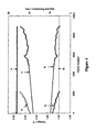
- a charging and discharging profile was developed to simulate typical charge and discharge demands on a 42-volt mild HEV battery typically used in mild HEV applications.
- the profile has short duration (2.35 minutes) and is composed of several current steps that simulate the power requirements of the battery during vehicle operation. These are, in order:
- the critical step is the cranking period over which the cell must deliver a current of 17.5A for 0.5 seconds.
- a cut-off voltage of 1.6-volts which is a common cut-off voltage value for batteries in the field of the invention, was set, and the batteries were subjected to repetitive cycling through the charge cycle until the lowest voltage during discharge reached the cut-off value.
- line 10 is the comparison battery internal resistance profile
- line 11 is the Example 1 battery internal resistance profile
- line 12 is the comparison battery minimum discharge voltage profile
- line 13 is the Example 1 battery minimum discharge voltage profile.
- the comparison battery performs about 2150 cycles, while the battery of Example 1 performs 8940 cycles before the minimum discharge voltages of each battery reaches the cut-off value of 1.6-volts (represented by line 15.
- the cycling performance of the battery of Example 1 is at least four times better than that of the comparison battery.
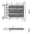
- the embodiment of this Example comprises three lead dioxide positive plate electrodes (2) and two composite negative electrodes (16).
- the composite negative electrodes comprise a current collector or grid (17) with the lead-containing paste composition described above applied to one region (the face) thereof (18) and capacitor high surface-area carbon electrode material-containing paste applied to the opposite face (19). Formation of the electrode is conducted in the manner known in the art.
- a lead based negative electrode is prepared with lead pasted by conventional dipping techniques to the main body section in lead paste material, followed by formation, and then the capacitor material is pasted to a region or regions of this lead based negative electrode, such as one face thereof.
- the positive (2) and negative composite electrodes (16) are positioned in an alternating arrangement as illustrated in Figure 5 in a battery case (4).
- the positive lead dioxide electrodes (2) and negative composite electrodes (16) of the embodiment illustrated in Figure 5 are 40 millimetres wide by 68 millimetres high by 3.3 millimetres thick.
- the carbon electrode region (19) of the negative electrode takes up 1.4 millimetres of the thickness of the negative electrode.
- AGM separators (5) of 2 millimetres in thickness are positioned between the lead-dioxide (2) and lead face (18) of the negative electrode, and microporous polypropylene separators (6) of 0.05 millimetres thickness are sandwiched between the positive electrodes (2) and carbon face of the negative electrode (19).
- AGM Absorptive glass microfibre
- the battery case (4) is filled with sulfuric acid solution (7).
- the positive electrodes are connected to a positive busbar (8), and the negative electrodes connected to a negative busbar (9).
- Example 1 Further testing on the battery of Example 1 showed that improvements in electrolyte dry-out could be achieved by matching the hydrogen evolution rate of the carbon electrode (3) during battery charging to be similar to that of the lead negative electrode (1). This was achieved by replacing the carbon electrode of Example 1 with a modified carbon electrode (103) with 2.5 wt% PbO and 2.5 wt% ZnO, 65 wt% activated carbon, 20 wt% carbon black and binder (10 wt%) in the paste composition.
- a modified carbon electrode (103) with 2.5 wt% PbO and 2.5 wt% ZnO, 65 wt% activated carbon, 20 wt% carbon black and binder (10 wt%) in the paste composition.
- FIG. 8 A further variation on the battery of Example 1 is illustrated in Figure 8 .
- the same numerals are used to refer to common features of the two batteries.
- the battery electrodes are illustrated.
- the battery further includes the separators, case, electrolyte, busbars, terminals and other features of batteries common in the art.
- the battery of this Example comprises an alternating series of positive and negative electrodes.
- the electrodes are, in order from left to right, a lead dioxide battery positive electrode (2), a lead-based battery negative electrode (3), a second lead dioxide battery positive electrode (2), a capacitor carbon and additive negative electrode of the type described in Example 3 (103), a capacitor-battery positive electrode as described further below (23), a second capacitor carbon and additive negative electrode of the type described in Example 3 (103), a second lead based battery negative electrode (3) and a third lead dioxide battery positive electrode (2).
- Each of the positive and negative electrodes, respectively, are connected to a positive conductor and a negative conductor, and to the positive and negative terminals of the battery.
- the capacitor-battery electrode (23) comprises a metal current collector, with a mixture of activated carbon (60 wt%), carbon black (20 wt%) and 10 wt% of lead oxide pasted thereon.
- the paste composition is formed with 10 wt%[5 wt% carboxymethyl cellulose and 5 wt% neoprene] binder and sintered onto the current collector.
- the electrode is about 0.8 mm thick. In gassing tests it was shown that the inclusion of SbO and red lead in this capacitor positive electrode has an advantageous effect on gassing, and therefore these additives may further be contained in the capacitor positive electrode.
- the battery of this Example can contain further alternating positive and negative electrodes of any type. Generally it is desirable to ensure that there is some level of matching the surface areas and hydrogen gassing rates of the sum of the positive and negative electrodes, and to include the requisite number of positive and negative electrodes to provide a battery of the desired voltage.
Landscapes
- Engineering & Computer Science (AREA)
- Chemical & Material Sciences (AREA)
- Power Engineering (AREA)
- Chemical Kinetics & Catalysis (AREA)
- Electrochemistry (AREA)
- General Chemical & Material Sciences (AREA)
- Microelectronics & Electronic Packaging (AREA)
- Materials Engineering (AREA)
- Manufacturing & Machinery (AREA)
- Inorganic Chemistry (AREA)
- Battery Electrode And Active Subsutance (AREA)
- Secondary Cells (AREA)
- Electric Double-Layer Capacitors Or The Like (AREA)
- Physical Or Chemical Processes And Apparatus (AREA)
- Cell Separators (AREA)
Priority Applications (1)
| Application Number | Priority Date | Filing Date | Title |
|---|---|---|---|
| PL10012506T PL2273602T3 (pl) | 2003-09-18 | 2004-09-16 | Urządzenia o wysokiej sprawności do magazynowania energii |
Applications Claiming Priority (2)
| Application Number | Priority Date | Filing Date | Title |
|---|---|---|---|
| AU2003905086A AU2003905086A0 (en) | 2003-09-18 | High performance lead-acid battery | |
| EP04761297A EP1665446B1 (de) | 2003-09-18 | 2004-09-16 | Hochleistungsfähige energiespeichereinrichtungen |
Related Parent Applications (2)
| Application Number | Title | Priority Date | Filing Date |
|---|---|---|---|
| EP04761297.3 Division | 2004-09-16 | ||
| EP04761297A Division EP1665446B1 (de) | 2003-09-18 | 2004-09-16 | Hochleistungsfähige energiespeichereinrichtungen |
Publications (3)
| Publication Number | Publication Date |
|---|---|
| EP2273602A2 true EP2273602A2 (de) | 2011-01-12 |
| EP2273602A3 EP2273602A3 (de) | 2011-07-20 |
| EP2273602B1 EP2273602B1 (de) | 2015-03-25 |
Family
ID=34280538
Family Applications (3)
| Application Number | Title | Priority Date | Filing Date |
|---|---|---|---|
| EP04761297A Expired - Lifetime EP1665446B1 (de) | 2003-09-18 | 2004-09-16 | Hochleistungsfähige energiespeichereinrichtungen |
| EP10012506.1A Expired - Lifetime EP2273602B1 (de) | 2003-09-18 | 2004-09-16 | Hochleistungsfähige energiespeichereinrichtungen |
| EP10012505.3A Expired - Lifetime EP2290737B1 (de) | 2003-09-18 | 2004-09-16 | Hochleistungsfähige energiespeichereinrichtungen |
Family Applications Before (1)
| Application Number | Title | Priority Date | Filing Date |
|---|---|---|---|
| EP04761297A Expired - Lifetime EP1665446B1 (de) | 2003-09-18 | 2004-09-16 | Hochleistungsfähige energiespeichereinrichtungen |
Family Applications After (1)
| Application Number | Title | Priority Date | Filing Date |
|---|---|---|---|
| EP10012505.3A Expired - Lifetime EP2290737B1 (de) | 2003-09-18 | 2004-09-16 | Hochleistungsfähige energiespeichereinrichtungen |
Country Status (11)
| Country | Link |
|---|---|
| US (2) | US7923151B2 (de) |
| EP (3) | EP1665446B1 (de) |
| JP (2) | JP4960702B2 (de) |
| KR (1) | KR101227779B1 (de) |
| CN (2) | CN100539287C (de) |
| AT (1) | ATE550804T1 (de) |
| AU (1) | AU2004273104B2 (de) |
| ES (3) | ES2537655T3 (de) |
| PL (3) | PL2273602T3 (de) |
| RU (1) | RU2335831C2 (de) |
| WO (1) | WO2005027255A1 (de) |
Cited By (1)
| Publication number | Priority date | Publication date | Assignee | Title |
|---|---|---|---|---|
| WO2013148893A1 (en) * | 2012-03-27 | 2013-10-03 | Johnson Controls Technology Company | Capacitor electrodes for lead-acid battery with surface-modified additives |
Families Citing this family (129)
| Publication number | Priority date | Publication date | Assignee | Title |
|---|---|---|---|---|
| PL2273602T3 (pl) | 2003-09-18 | 2015-10-30 | Commw Scient Ind Res Org | Urządzenia o wysokiej sprawności do magazynowania energii |
| JP2006252902A (ja) * | 2005-03-10 | 2006-09-21 | Kawasaki Heavy Ind Ltd | ハイブリッド電池 |
| EP3138702B1 (de) * | 2005-03-18 | 2019-11-13 | Gatekeeper Systems, Inc. | Zweiwege-kommunikationssystem zur verfolgung von standort und status eines radfahrzeuges |
| JP5092272B2 (ja) * | 2005-05-31 | 2012-12-05 | 新神戸電機株式会社 | 鉛蓄電池および鉛蓄電池の製造方法 |
| US20070045018A1 (en) | 2005-08-25 | 2007-03-01 | Carter Scott J | Systems and methods for controlling powered vehicles near a restricted region |
| US20070128472A1 (en) * | 2005-10-27 | 2007-06-07 | Tierney T K | Cell Assembly and Casing Assembly for a Power Storage Device |
| EP1961022A4 (de) * | 2005-11-22 | 2014-08-06 | Maxwell Technologies Inc | Ultrakondensator-drucksteuersystem |
| KR100614118B1 (ko) * | 2006-02-24 | 2006-08-22 | 주식회사 비츠로셀 | 하이브리드 전지 |
| JP2008047452A (ja) * | 2006-08-18 | 2008-02-28 | Shin Kobe Electric Mach Co Ltd | ペースト式電極板及びその製造方法 |
| US7658247B2 (en) * | 2006-09-20 | 2010-02-09 | Gatekeeper Systems, Inc. | Systems and methods for power storage and management from intermittent power sources |
| US8202653B2 (en) | 2006-10-23 | 2012-06-19 | Axion Power International, Inc. | Electrode with reduced resistance grid and hybrid energy storage device having same |
| US20090035657A1 (en) * | 2006-10-23 | 2009-02-05 | Buiel Edward R | Electrode for Hybrid Energy Storage Device and Method of Making Same |
| MX2009004311A (es) | 2006-10-23 | 2009-08-07 | Axion Power Int Inc | Dispositivo de almacenamiento de energia hibrida y metodo de elaboracion del mismo. |
| US20080113268A1 (en) * | 2006-10-23 | 2008-05-15 | Buiel Edward R | Recombinant Hybrid Energy Storage Device |
| US7881042B2 (en) * | 2006-10-26 | 2011-02-01 | Axion Power International, Inc. | Cell assembly for an energy storage device with activated carbon electrodes |
| US7835136B2 (en) | 2006-11-15 | 2010-11-16 | Energ2, Inc. | Electric double layer capacitance device |
| JP4997948B2 (ja) * | 2006-12-07 | 2012-08-15 | 新神戸電機株式会社 | 鉛蓄電池 |
| AR064292A1 (es) * | 2006-12-12 | 2009-03-25 | Commw Scient Ind Res Org | Dispositivo mejorado para almacenamiento de energia |
| AR067238A1 (es) | 2007-03-20 | 2009-10-07 | Commw Scient Ind Res Org | Dispositivos optimizados para el almacenamiento de energia |
| US7761198B2 (en) | 2007-06-25 | 2010-07-20 | General Electric Company | Methods and systems for power system management |
| US20090103242A1 (en) * | 2007-10-19 | 2009-04-23 | Axion Power International, Inc. | Electrode with Reduced Resistance Grid and Hybrid Energy Storage Device Having Same |
| FR2927472B1 (fr) * | 2008-02-11 | 2010-07-30 | Commissariat Energie Atomique | Systeme hybride de stockage d'energie electrique a electrodes bipolaires |
| JP5106174B2 (ja) * | 2008-02-25 | 2012-12-26 | 三洋電機株式会社 | 固体電解コンデンサの製造方法 |
| CN101978532B (zh) * | 2008-03-24 | 2013-11-13 | 日本瑞翁株式会社 | 铅蓄电池用电极及其利用 |
| JP5412909B2 (ja) * | 2008-03-24 | 2014-02-12 | 日本ゼオン株式会社 | 鉛蓄電池用電極および鉛蓄電池 |
| WO2009137422A1 (en) * | 2008-05-05 | 2009-11-12 | Gatekeeper Systems, Inc. | Brake mechanism for a non-motorized wheeled vehicle |
| RU2371816C1 (ru) * | 2008-08-13 | 2009-10-27 | Общество с ограниченной ответственностью Завод "Саратовгазавтоматика" | Термоэлектрический блок питания |
| WO2010032785A1 (ja) | 2008-09-22 | 2010-03-25 | 日本ゼオン株式会社 | 鉛蓄電池用電極および鉛蓄電池 |
| EP2366663A4 (de) | 2008-10-15 | 2016-12-21 | Cataler Corp | Carbonmaterial und speicherelement daraus |
| US8232005B2 (en) | 2008-11-17 | 2012-07-31 | Eliot Gerber | Lead acid battery with titanium core grids and carbon based grids |
| EP2379325B1 (de) | 2008-12-18 | 2023-07-26 | Molecular Rebar Design, LLC | Exfolierte kohlenstoffnanoröhren, verfahren zu ihrer herstellung und daraus gewonnene produkte |
| US9450232B2 (en) | 2009-04-23 | 2016-09-20 | Commonwealth Scientific And Industrial Research Organisation | Process for producing negative plate for lead storage battery, and lead storage battery |
| JP2011009128A (ja) * | 2009-06-29 | 2011-01-13 | Gs Yuasa Corp | キャパシタハイブリッド鉛蓄電池及びその製造方法 |
| JP5795309B2 (ja) | 2009-07-01 | 2015-10-14 | ビーエーエスエフ ソシエタス・ヨーロピアBasf Se | 超高純度の合成炭素材料 |
| CN102576607A (zh) | 2009-07-27 | 2012-07-11 | 纸电池公司 | 柔性能量储存结构薄片 |
| US20110027653A1 (en) * | 2009-08-03 | 2011-02-03 | Ho Marvin C | Negative plate for lead acid battery |
| JP5711483B2 (ja) | 2009-08-27 | 2015-04-30 | 古河電池株式会社 | 鉛蓄電池用複合キャパシタ負極板の製造法及び鉛蓄電池 |
| JP5797384B2 (ja) | 2009-08-27 | 2015-10-21 | 古河電池株式会社 | 鉛蓄電池用複合キャパシタ負極板及び鉛蓄電池 |
| CN102725883B (zh) | 2009-08-27 | 2015-08-26 | 联邦科学和工业研究组织 | 电存储装置及其电极 |
| US8737547B2 (en) | 2009-10-26 | 2014-05-27 | Indian Institute Of Science | Adaptive digital baseband receiver |
| CN105070518B (zh) | 2009-11-02 | 2018-05-29 | 卡博特公司 | 用于储能应用的高表面积低结构炭黑 |
| PL2497137T3 (pl) | 2009-11-02 | 2020-03-31 | Cabot Corporation | Baterie ołowiowo-kwasowe i pasty do nich |
| US9912009B2 (en) | 2009-12-18 | 2018-03-06 | Molecular Rebar Design, Llc | Binders, electrolytes and separator films for energy storage and collection devices using discrete carbon nanotubes |
| CN102110861A (zh) * | 2009-12-25 | 2011-06-29 | 旭丽电子(广州)有限公司 | 电池保护方法和系统 |
| US20110189507A1 (en) * | 2010-02-03 | 2011-08-04 | International Battery, Inc. | Extended energy storage unit |
| US8481203B2 (en) * | 2010-02-03 | 2013-07-09 | Bren-Tronies Batteries International, L.L.C. | Integrated energy storage unit |
| US8593787B2 (en) * | 2010-04-21 | 2013-11-26 | Corning Incorporated | Electrochemical capacitor having lithium containing electrolyte |
| US9036332B2 (en) | 2010-06-22 | 2015-05-19 | Indian Institute Of Science | Energy storage device, an inorganic gelled electrolyte and methods thereof |
| KR101483202B1 (ko) | 2010-06-22 | 2015-01-15 | 인디안 인스티투트 오브 싸이언스 | 에너지 저장 장치 및 그 방법 |
| CN103261090A (zh) | 2010-09-30 | 2013-08-21 | 艾纳G2技术公司 | 储能颗粒的增强式装填 |
| US20120098501A1 (en) * | 2010-10-26 | 2012-04-26 | Tesla Motors, Inc. | Efficient lead acid battery charging |
| US20120116381A1 (en) | 2010-11-05 | 2012-05-10 | Houser Kevin L | Surgical instrument with charging station and wireless communication |
| US10881448B2 (en) | 2010-11-05 | 2021-01-05 | Ethicon Llc | Cam driven coupling between ultrasonic transducer and waveguide in surgical instrument |
| US9597143B2 (en) | 2010-11-05 | 2017-03-21 | Ethicon Endo-Surgery, Llc | Sterile medical instrument charging device |
| US10085792B2 (en) | 2010-11-05 | 2018-10-02 | Ethicon Llc | Surgical instrument with motorized attachment feature |
| US10660695B2 (en) | 2010-11-05 | 2020-05-26 | Ethicon Llc | Sterile medical instrument charging device |
| US9381058B2 (en) | 2010-11-05 | 2016-07-05 | Ethicon Endo-Surgery, Llc | Recharge system for medical devices |
| US9782215B2 (en) | 2010-11-05 | 2017-10-10 | Ethicon Endo-Surgery, Llc | Surgical instrument with ultrasonic transducer having integral switches |
| US9421062B2 (en) | 2010-11-05 | 2016-08-23 | Ethicon Endo-Surgery, Llc | Surgical instrument shaft with resiliently biased coupling to handpiece |
| US9072523B2 (en) | 2010-11-05 | 2015-07-07 | Ethicon Endo-Surgery, Inc. | Medical device with feature for sterile acceptance of non-sterile reusable component |
| US9510895B2 (en) | 2010-11-05 | 2016-12-06 | Ethicon Endo-Surgery, Llc | Surgical instrument with modular shaft and end effector |
| US10959769B2 (en) | 2010-11-05 | 2021-03-30 | Ethicon Llc | Surgical instrument with slip ring assembly to power ultrasonic transducer |
| US9782214B2 (en) | 2010-11-05 | 2017-10-10 | Ethicon Llc | Surgical instrument with sensor and powered control |
| US9375255B2 (en) | 2010-11-05 | 2016-06-28 | Ethicon Endo-Surgery, Llc | Surgical instrument handpiece with resiliently biased coupling to modular shaft and end effector |
| US20120116265A1 (en) | 2010-11-05 | 2012-05-10 | Houser Kevin L | Surgical instrument with charging devices |
| SG190926A1 (en) | 2010-12-14 | 2013-07-31 | Styron Europe Gmbh | Improved elastomer formulations |
| JP2012133959A (ja) | 2010-12-21 | 2012-07-12 | Furukawa Battery Co Ltd:The | 鉛蓄電池用複合キャパシタ負極板及び鉛蓄電池 |
| KR102048196B1 (ko) * | 2010-12-28 | 2019-11-25 | 바스프 에스이 | 향상된 전기화학적 특성을 포함하는 탄소 물질 |
| US8765297B2 (en) * | 2011-01-04 | 2014-07-01 | Exide Technologies | Advanced graphite additive for enhanced cycle-life of lead-acid batteries |
| US20120262127A1 (en) | 2011-04-15 | 2012-10-18 | Energ2 Technologies, Inc. | Flow ultracapacitor |
| US9365939B2 (en) | 2011-05-31 | 2016-06-14 | Wisconsin Alumni Research Foundation | Nanoporous materials for reducing the overpotential of creating hydrogen by water electrolysis |
| EP2715840B1 (de) * | 2011-06-03 | 2015-05-27 | Basf Se | Kohlenstoff-blei-mischungen zur verwendung in hybriden energiespeichereinrichtungen |
| EP3355394B1 (de) * | 2011-06-15 | 2020-09-16 | University of Southern California | Hocheffiziente eisenelektrode und additive zur verwendung in wiederaufladbaren eisenbasierten batterien |
| CN103764553B (zh) | 2011-06-23 | 2016-05-11 | 分子钢筋设计有限责任公司 | 纳米片-纳米管复合材料、其生产方法以及由其获得的产品 |
| CN103765642B (zh) | 2011-06-23 | 2016-07-06 | 分子钢筋设计有限责任公司 | 包含离散的碳纳米管的铅酸电池制剂 |
| JP6210980B2 (ja) | 2011-06-23 | 2017-10-11 | モレキュラー レバー デザイン,エルエルシー | 離散カーボンナノチューブを用いたリチウムイオン電池、その製造方法およびそれから得られる生成物 |
| US9997785B2 (en) | 2011-06-23 | 2018-06-12 | Molecular Rebar Design, Llc | Nanoplate-nanotube composites, methods for production thereof and products obtained therefrom |
| EP2731189A4 (de) * | 2011-07-05 | 2015-04-08 | Gs Yuasa Int Ltd | Geflutete bleisäurebatterie |
| CN102306555B (zh) * | 2011-08-23 | 2013-04-17 | 华南师范大学 | 一种超级电池用炭负极板 |
| CN102306844B (zh) * | 2011-09-01 | 2016-03-16 | 奇瑞汽车股份有限公司 | 一种超级电容蓄电池 |
| US8808914B2 (en) | 2012-01-13 | 2014-08-19 | Energy Power Systems, LLC | Lead-acid battery design having versatile form factor |
| US9595360B2 (en) | 2012-01-13 | 2017-03-14 | Energy Power Systems LLC | Metallic alloys having amorphous, nano-crystalline, or microcrystalline structure |
| US9263721B2 (en) | 2012-01-13 | 2016-02-16 | Energy Power Systems LLC | Lead-acid battery design having versatile form factor |
| WO2013120011A1 (en) | 2012-02-09 | 2013-08-15 | Energ2 Technologies, Inc. | Preparation of polymeric resins and carbon materials |
| US20140377596A1 (en) * | 2012-03-14 | 2014-12-25 | Energy Power Systems, LLC | Hybrid battery system for electric and hybrid electric vehicles |
| US20130244063A1 (en) * | 2012-03-14 | 2013-09-19 | Energy Power Systems LLC | Hybrid battery system for electric and hybrid electric vehicles |
| US8597996B1 (en) * | 2012-05-10 | 2013-12-03 | Universal Supercapacitors Llc | Method of manufacturing heterogeneous electrochemical capacitors having a double electric layer and of manufacturing and balancing the coulombic capacities of electrodes for use therein |
| CA2878227A1 (en) | 2012-07-08 | 2014-01-16 | Molecular Rebar Design, Llc | Polyurethane polymers and compositions made using discrete carbon nanotube molecular rebar |
| CN102881866B (zh) * | 2012-09-29 | 2017-03-01 | 浙江南都电源动力股份有限公司 | 一种含有铅石墨烯复合材料的铅炭电池负极板 |
| US9892865B2 (en) | 2012-10-17 | 2018-02-13 | Ramot At Tel Aviv University Ltd. | Super hybrid capacitor |
| US20140120386A1 (en) * | 2012-10-31 | 2014-05-01 | Exide Technologies | Over-Saturated Absorbed Glass Mat Valve Regulated Lead-Acid Battery Comprising Carbon Additives |
| US10014520B2 (en) * | 2012-10-31 | 2018-07-03 | Exide Technologies Gmbh | Composition that enhances deep cycle performance of valve-regulated lead-acid batteries filled with gel electrolyte |
| CN105190948B (zh) | 2013-03-14 | 2019-04-26 | 14族科技公司 | 包含锂合金化的电化学改性剂的复合碳材料 |
| US9812732B2 (en) | 2013-08-16 | 2017-11-07 | Johnson Controls Technology Company | Dual storage system and method with lithium ion and lead acid battery cells |
| CA2924489C (en) | 2013-09-30 | 2020-09-22 | Molecular Rebar Design, Llc | High carbon nanotube content fluids |
| EP3062372A4 (de) | 2013-10-16 | 2017-07-19 | Suzhou Hans Energy Storage Technology Co. Ltd. | Superbatterie und superkondensator mit einem material auf wolframbasis |
| US10195583B2 (en) | 2013-11-05 | 2019-02-05 | Group 14 Technologies, Inc. | Carbon-based compositions with highly efficient volumetric gas sorption |
| TWI479717B (zh) | 2013-11-28 | 2015-04-01 | Csb Battery Co Ltd | Lead-acid capacitor batteries and the preparation of lead-acid battery method |
| FR3016245B1 (fr) * | 2014-01-03 | 2021-07-16 | Commissariat Energie Atomique | Cellule electrochimique, systeme de stockage et de restitution d'energie electrique comprenant une telle cellule electrochimique et vehicule comprenant un tel systeme |
| US20150214710A1 (en) * | 2014-01-27 | 2015-07-30 | Humberto Arenas | Portable grounding system |
| KR102663138B1 (ko) | 2014-03-14 | 2024-05-03 | 그룹14 테크놀로지스, 인코포레이티드 | 용매의 부재하의 졸-겔 중합을 위한 신규한 방법 및 그러한 방법으로부터의 가변형 탄소 구조의 생성 |
| US20150357643A1 (en) * | 2014-06-10 | 2015-12-10 | Cabot Corporation | Electrode compositions comprising carbon additives |
| US10136938B2 (en) | 2014-10-29 | 2018-11-27 | Ethicon Llc | Electrosurgical instrument with sensor |
| JP6732771B2 (ja) | 2015-02-26 | 2020-07-29 | ダラミック エルエルシー | 改善された水分損失能力のための鉛酸電池用の蒸気圧バリア、セパレータ、システム、及びその製造及び使用方法 |
| US11473202B2 (en) | 2015-04-13 | 2022-10-18 | Attostat, Inc. | Anti-corrosion nanoparticle compositions |
| JP6725545B2 (ja) | 2015-06-24 | 2020-07-22 | キャボット コーポレイションCabot Corporation | 鉛酸蓄電池用炭素質材料 |
| JP2015216123A (ja) * | 2015-07-15 | 2015-12-03 | 株式会社Gsユアサ | 液式鉛蓄電池 |
| WO2017031006A1 (en) | 2015-08-14 | 2017-02-23 | Energ2 Technologies, Inc. | Composites of porous nano-featured silicon materials and carbon materials |
| KR102637617B1 (ko) | 2015-08-28 | 2024-02-19 | 그룹14 테크놀로지스, 인코포레이티드 | 극도로 내구성이 우수한 리튬 인터칼레이션을 나타내는 신규 물질 및 그의 제조 방법 |
| CN105355980B (zh) * | 2015-11-06 | 2018-02-16 | 深圳市力赛科技有限公司 | 一种铝电解电容器型锂离子电池的制备方法 |
| CN105355848B (zh) * | 2015-11-06 | 2018-05-29 | 广东石油化工学院 | 一种铝电解电容器型锂离子电池 |
| CN105406133A (zh) * | 2015-11-30 | 2016-03-16 | 李朝 | 一种高安全性的铝电解电容器型钴酸锂锂离子电池 |
| WO2017142522A1 (en) * | 2016-02-17 | 2017-08-24 | Daramic, Llc | Improved battery separators which reduce water loss in lead acid batteries and improved lead acid batteries including such improved battery separators |
| CN106099209B (zh) * | 2016-06-17 | 2017-09-22 | 湖北骆驼海峡新型蓄电池有限公司 | 一种动力铅酸蓄电池电解液添加剂及其制备方法 |
| CN107565086B (zh) | 2016-06-30 | 2022-12-13 | 卢云峰 | 一种电池极板制备方法 |
| CN110582823A (zh) | 2017-03-09 | 2019-12-17 | 14集团技术公司 | 含硅前体在多孔支架材料上的分解 |
| US11936032B2 (en) | 2017-06-09 | 2024-03-19 | Cps Technology Holdings Llc | Absorbent glass mat battery |
| MX2019014765A (es) | 2017-06-09 | 2020-07-22 | Cps Tech Holdings Llc | Bateria con estera de vidrio absorbente. |
| US11646453B2 (en) | 2017-11-28 | 2023-05-09 | Attostat, Inc. | Nanoparticle compositions and methods for enhancing lead-acid batteries |
| GB2570112B (en) * | 2018-01-10 | 2022-12-14 | Zapgo Ltd | Hybrid energy pack |
| US11549631B2 (en) | 2018-01-10 | 2023-01-10 | Lydall, Inc. | Asymmetrical stretch composite for pipe liner |
| CN108387797B (zh) * | 2018-02-06 | 2024-07-12 | 天能电池集团股份有限公司 | 一种用于检测蓄电池电极材料性能的装置和方法 |
| IT201800005943A1 (it) * | 2018-06-01 | 2019-12-01 | Dispositivo elettrochimico a commutazione automatica per l’accumulo ad alta energia e ad alta potenza | |
| US11174167B1 (en) | 2020-08-18 | 2021-11-16 | Group14 Technologies, Inc. | Silicon carbon composites comprising ultra low Z |
| US11335903B2 (en) | 2020-08-18 | 2022-05-17 | Group14 Technologies, Inc. | Highly efficient manufacturing of silicon-carbon composites materials comprising ultra low z |
| US11639292B2 (en) | 2020-08-18 | 2023-05-02 | Group14 Technologies, Inc. | Particulate composite materials |
| WO2022072715A1 (en) | 2020-09-30 | 2022-04-07 | Group14 Technologies, Inc. | Methods of passivation to control oxygen content and reactivity of silicon-carbon composite materials |
| US12456759B2 (en) | 2021-03-30 | 2025-10-28 | Evoq Nano, Inc. | Nanoparticle-enhanced lead-acid electrode paste and improved lead-acid batteries made therefrom |
| CN114039041B (zh) * | 2021-11-04 | 2022-09-09 | 昆明理工恒达科技股份有限公司 | 一种大容量铅炭储能电池及制备方法 |
Family Cites Families (154)
| Publication number | Priority date | Publication date | Assignee | Title |
|---|---|---|---|---|
| JP2856162B2 (ja) | 1996-07-30 | 1999-02-10 | 日本電気株式会社 | 電気二重層コンデンサ及びその製造方法 |
| US4215190A (en) | 1979-06-08 | 1980-07-29 | Ferrando William A | Lightweight battery electrode |
| DE3436290A1 (de) | 1983-10-08 | 1985-04-25 | Honda Giken Kogyo K.K., Tokio/Tokyo | Abgedichtete blei-saeure-batterie |
| US4882132A (en) | 1983-12-27 | 1989-11-21 | Monsanto Company | Solvent extraction of cobalt using hydroxamic acids |
| US4975253A (en) | 1983-12-27 | 1990-12-04 | Monsanto Company | Solvent extraction of nickel using hydroxamic acids |
| US4567284A (en) | 1983-12-27 | 1986-01-28 | Monsanto Company | Cobalt complex of N-alkylalkanohydroxamic acid |
| US4770954A (en) | 1987-10-16 | 1988-09-13 | Halliburton Company | Switching power supply and method |
| WO1989006865A1 (fr) | 1988-01-22 | 1989-07-27 | Japan Storage Battery Co. Ltd. | Batterie d'accumulateurs alcalins et procede de production |
| JP2541342B2 (ja) * | 1990-06-06 | 1996-10-09 | 株式会社ユアサコーポレーション | ハイブリット電池 |
| CH678556A5 (de) | 1990-12-17 | 1991-09-30 | Hugues Edwin Luedi Baertschi | |
| US5154989A (en) | 1991-09-04 | 1992-10-13 | Medtronic, Inc. | Energy storage device |
| US5260855A (en) | 1992-01-17 | 1993-11-09 | Kaschmitter James L | Supercapacitors based on carbon foams |
| FR2692077A1 (fr) | 1992-06-03 | 1993-12-03 | Sorapec | Accumulateurs à électrodes bipolaires. |
| US5464453A (en) | 1992-09-18 | 1995-11-07 | Pinnacle Research Institute, Inc. | Method to fabricate a reliable electrical storage device and the device thereof |
| US5384685A (en) | 1992-09-18 | 1995-01-24 | Pinnacle Research Institute, Inc. | Screen printing of microprotrusions for use as a space separator in an electrical storage device |
| WO1994007272A1 (en) | 1992-09-18 | 1994-03-31 | Pinnacle Research Institute, Inc. | Energy storage device and methods of manufacture |
| US5491399A (en) | 1993-05-28 | 1996-02-13 | William E. Gregory | Lead acid battery rejuvenator |
| US5604426A (en) | 1993-06-30 | 1997-02-18 | Asahi Glass Company Ltd. | Electric apparatus with a power supply including an electric double layer capacitor |
| JP3185508B2 (ja) | 1993-12-29 | 2001-07-11 | 日本電池株式会社 | 密閉形鉛蓄電池 |
| US5429893A (en) | 1994-02-04 | 1995-07-04 | Motorola, Inc. | Electrochemical capacitors having dissimilar electrodes |
| US5439756A (en) * | 1994-02-28 | 1995-08-08 | Motorola, Inc. | Electrical energy storage device and method of charging and discharging same |
| US5419977A (en) | 1994-03-09 | 1995-05-30 | Medtronic, Inc. | Electrochemical device having operatively combined capacitor |
| JPH07249405A (ja) | 1994-03-10 | 1995-09-26 | Haibaru:Kk | 電 池 |
| US5518833A (en) | 1994-05-24 | 1996-05-21 | Eagle-Picher Industries, Inc. | Nonwoven electrode construction |
| US5458043A (en) | 1994-07-28 | 1995-10-17 | The United States Of America As Represented By The Secretary Of The Air Force | Battery charging capacitors electromagnetic launcher |
| US5705259A (en) | 1994-11-17 | 1998-01-06 | Globe-Union Inc. | Method of using a bipolar electrochemical storage device |
| US5526223A (en) * | 1994-12-01 | 1996-06-11 | Motorola, Inc. | Electrode materials and electrochemical capacitors using same |
| US5574353A (en) | 1995-03-31 | 1996-11-12 | Motorola, Inc. | Electrochemical charge storage device having constant voltage discharge |
| US5587250A (en) | 1995-09-27 | 1996-12-24 | Motorola, Inc. | Hybrid energy storage system |
| US5626729A (en) | 1996-02-01 | 1997-05-06 | Motorola, Inc. | Modified polymer electrodes for energy storage devices and method of making same |
| JPH1021900A (ja) * | 1996-07-01 | 1998-01-23 | Tokuyama Corp | 密閉型鉛蓄電池用正極板および密閉型鉛蓄電池 |
| US5821007A (en) | 1996-08-19 | 1998-10-13 | Motorola, Inc. | Power source for an electrical device |
| JPH1094182A (ja) | 1996-09-13 | 1998-04-10 | Honda Motor Co Ltd | 電源装置および電気自動車 |
| US5849426A (en) | 1996-09-20 | 1998-12-15 | Motorola, Inc. | Hybrid energy storage system |
| US5670266A (en) | 1996-10-28 | 1997-09-23 | Motorola, Inc. | Hybrid energy storage system |
| JP3661725B2 (ja) | 1996-12-20 | 2005-06-22 | 旭硝子株式会社 | 電源装置 |
| US5744258A (en) | 1996-12-23 | 1998-04-28 | Motorola,Inc. | High power, high energy, hybrid electrode and electrical energy storage device made therefrom |
| US6011379A (en) | 1997-03-12 | 2000-01-04 | U.S. Nanocorp, Inc. | Method for determining state-of-charge using an intelligent system |
| US5993983C1 (en) | 1997-03-14 | 2001-09-18 | Century Mfg Co | Portable power supply using hybrid battery technology |
| US5935724A (en) | 1997-04-04 | 1999-08-10 | Wilson Greatbatch Ltd. | Electrochemical cell having multiplate electrodes with differing discharge rate regions |
| US5935728A (en) | 1997-04-04 | 1999-08-10 | Wilson Greatbatch Ltd. | Electrochemical cell having multiplate and jellyroll electrodes with differing discharge rate regions |
| US5916699A (en) | 1997-05-13 | 1999-06-29 | Motorola, Inc. | Hybrid energy storage system |
| BR9705871C3 (pt) | 1997-05-26 | 2004-08-10 | Guacemmi Participacoees Societ | Sistema radiante em acumuladores e produto resultante |
| US6316563B2 (en) | 1997-05-27 | 2001-11-13 | Showa Denko K.K. | Thermopolymerizable composition and use thereof |
| US6087812A (en) | 1997-06-13 | 2000-07-11 | Motorola, Inc. | Independent dual-switch system for extending battery life under transient loads |
| US5821006A (en) | 1997-07-07 | 1998-10-13 | Motorola, Inc. | Hybrid cell/capacitor assembly for use in a battery pack |
| JPH1141664A (ja) | 1997-07-24 | 1999-02-12 | Toshiba Corp | 無線電話装置 |
| US6117585A (en) * | 1997-07-25 | 2000-09-12 | Motorola, Inc. | Hybrid energy storage device |
| US6190805B1 (en) | 1997-09-10 | 2001-02-20 | Showa Denko Kabushiki Kaisha | Polymerizable compound, solid polymer electrolyte using the same and use thereof |
| AU719684B2 (en) | 1997-11-11 | 2000-05-18 | Zakrytoe Aktsionernoe Obschestvo "Esma" | Capacitor with dual electric layer |
| US6610440B1 (en) | 1998-03-10 | 2003-08-26 | Bipolar Technologies, Inc | Microscopic batteries for MEMS systems |
| US6765363B2 (en) | 1998-03-10 | 2004-07-20 | U.S. Microbattery, Inc. | Micro power supply with integrated charging capability |
| DE19815127A1 (de) | 1998-04-03 | 1999-10-07 | Basf Ag | Mittel mit Copolymerisaten aus N-Vinylcarbonsäureamiden und Monomeren mit hydrophobem Rest, und Verwendung dieser Copolymerisate |
| US6088217A (en) * | 1998-05-31 | 2000-07-11 | Motorola, Inc. | Capacitor |
| US6208502B1 (en) | 1998-07-06 | 2001-03-27 | Aerovox, Inc. | Non-symmetric capacitor |
| EP1115130A4 (de) | 1998-08-25 | 2007-05-02 | Fuji Heavy Ind Ltd | Elektrodematerial und herstellungsverfahren |
| US6331365B1 (en) | 1998-11-12 | 2001-12-18 | General Electric Company | Traction motor drive system |
| RU2140681C1 (ru) * | 1998-11-27 | 1999-10-27 | Разумов Сергей Николаевич | Асимметричный электрохимический конденсатор |
| US6222723B1 (en) * | 1998-12-07 | 2001-04-24 | Joint Stock Company “Elton” | Asymmetric electrochemical capacitor and method of making |
| US6252762B1 (en) * | 1999-04-21 | 2001-06-26 | Telcordia Technologies, Inc. | Rechargeable hybrid battery/supercapacitor system |
| JP3820149B2 (ja) | 1999-06-25 | 2006-09-13 | ザ ボード オブ トラスティーズ オブ ザ ユニバーシティ オブ イリノイ | 動的切換可能な電力変換器 |
| US6310789B1 (en) | 1999-06-25 | 2001-10-30 | The Procter & Gamble Company | Dynamically-controlled, intrinsically regulated charge pump power converter |
| JP3348405B2 (ja) | 1999-07-22 | 2002-11-20 | エヌイーシートーキン株式会社 | インドール系高分子を用いた二次電池及びキャパシタ |
| US20030129458A1 (en) | 1999-09-02 | 2003-07-10 | John C. Bailey | An energy system for delivering intermittent pulses |
| JP2001110418A (ja) | 1999-10-13 | 2001-04-20 | Toyota Central Res & Dev Lab Inc | リチウム二次電池用正極およびそれを用いたリチウム二次電池 |
| US6576365B1 (en) | 1999-12-06 | 2003-06-10 | E.C.R. - Electro Chemical Research Ltd. | Ultra-thin electrochemical energy storage devices |
| EP1126536B1 (de) | 2000-02-16 | 2007-05-16 | Nisshinbo Industries, Inc. | Mehrschichtelektrodenstruktur und Verfahren für ihre Herstellung |
| JP2001284188A (ja) | 2000-04-03 | 2001-10-12 | Asahi Glass Co Ltd | 電気二重層キャパシタ電極用炭素材料の製造方法及びこの炭素材料を用いた電気二重層キャパシタの製造方法 |
| KR100359055B1 (ko) | 2000-04-25 | 2002-11-07 | 한국과학기술연구원 | 박막형 슈퍼 캐패시터 및 그 제조방법 |
| JP2001319655A (ja) | 2000-05-10 | 2001-11-16 | Nec Corp | ポリキノキサリンエーテルを用いた2次電池及びキャパシター |
| JP2001332264A (ja) | 2000-05-25 | 2001-11-30 | Shin Kobe Electric Mach Co Ltd | 小形制御弁式鉛蓄電池 |
| AU2001275330A1 (en) | 2000-06-07 | 2001-12-17 | Marc D. Andelman | Fluid and electrical connected flow-through electrochemical cells, system and method |
| JP4825344B2 (ja) | 2000-06-07 | 2011-11-30 | Fdk株式会社 | 電池・キャパシタ複合素子 |
| US20020037452A1 (en) | 2000-06-23 | 2002-03-28 | Schmidt David G. | Novel compositions for use in batteries, capacitors, fuel cells and similar devices and for hydrogen production |
| US6333123B1 (en) | 2000-06-28 | 2001-12-25 | The Gillette Company | Hydrogen recombination catalyst |
| US6541140B1 (en) | 2000-08-07 | 2003-04-01 | Wilson Greatbatch Technologies, Inc. | Electrochemical lithium ion secondary cell having multiplate electrodes with differing discharge rate regions |
| US6623884B1 (en) | 2000-08-07 | 2003-09-23 | Wilson Greatbatch Ltd. | Electrochemical lithium ion secondary cell having multiplate and jellyroll electrodes with differing discharge rate regions |
| JP3471304B2 (ja) | 2000-09-18 | 2003-12-02 | Necトーキン株式会社 | インドール系化合物を用いた二次電池及びキャパシタ |
| US6517972B1 (en) | 2000-09-29 | 2003-02-11 | Telcordia Technologies, Inc. | High energy density hybrid battery/supercapacitor system |
| JP2002118036A (ja) | 2000-10-10 | 2002-04-19 | Sanshin:Kk | 蓄電用電子部品および複合電極体 |
| CN1357899A (zh) | 2000-12-13 | 2002-07-10 | 中国科学院成都有机化学研究所 | 碳纳米管用于超级电容器电极材料 |
| US7119047B1 (en) | 2001-02-26 | 2006-10-10 | C And T Company, Inc. | Modified activated carbon for capacitor electrodes and method of fabrication thereof |
| US7110242B2 (en) | 2001-02-26 | 2006-09-19 | C And T Company, Inc. | Electrode for electric double layer capacitor and method of fabrication thereof |
| JP2002298853A (ja) | 2001-03-28 | 2002-10-11 | Tagawa Kazuo | リチウム二次電池および電気二重層キャパシタ |
| EP1248307A1 (de) | 2001-04-03 | 2002-10-09 | Hitachi, Ltd. | Bleisäurebatterie |
| JP3573102B2 (ja) | 2001-04-20 | 2004-10-06 | ソニー株式会社 | 負極活物質及び非水電解質二次電池 |
| WO2002087006A1 (en) | 2001-04-24 | 2002-10-31 | Reveo, Inc. | Hybrid electrochemical cell system |
| US6466429B1 (en) | 2001-05-03 | 2002-10-15 | C And T Co., Inc. | Electric double layer capacitor |
| US6628504B2 (en) | 2001-05-03 | 2003-09-30 | C And T Company, Inc. | Electric double layer capacitor |
| US6653014B2 (en) | 2001-05-30 | 2003-11-25 | Birch Point Medical, Inc. | Power sources for iontophoretic drug delivery systems |
| WO2002099956A2 (en) | 2001-06-05 | 2002-12-12 | Us Microbattery, Inc. | Micro power supply with integrated charging capability |
| US20040121204A1 (en) | 2001-06-07 | 2004-06-24 | Adelman Marc D. | Fluid electrical connected flow-through electrochemical cells, system and method |
| JP4364460B2 (ja) * | 2001-08-07 | 2009-11-18 | 古河電池株式会社 | 鉛蓄電池用負極 |
| KR20030014988A (ko) | 2001-08-14 | 2003-02-20 | 한국전자통신연구원 | 하이브리드 전원소자 및 그 제조방법 |
| JP3794553B2 (ja) | 2001-09-06 | 2006-07-05 | 株式会社デンソー | リチウム二次電池電極及びリチウム二次電池 |
| JP3815774B2 (ja) | 2001-10-12 | 2006-08-30 | 松下電器産業株式会社 | 電解質を含む電気化学素子 |
| JP4004769B2 (ja) | 2001-10-17 | 2007-11-07 | Necトーキン株式会社 | 電解液、並びにこれを用いた電気化学セル |
| WO2003055791A2 (en) | 2001-10-17 | 2003-07-10 | Applied Materials, Inc. | Improved etch process for etching microstructures |
| FR2831318B1 (fr) | 2001-10-22 | 2006-06-09 | Commissariat Energie Atomique | Dispositif de stockage d'energie a recharge rapide, sous forme de films minces |
| JP2003132941A (ja) | 2001-10-29 | 2003-05-09 | Matsushita Electric Ind Co Ltd | コンデンサ一体型の固体電解質二次電池 |
| JP3809549B2 (ja) | 2001-11-22 | 2006-08-16 | 株式会社日立製作所 | 電源装置と分散型電源システムおよびこれを搭載した電気自動車 |
| JP2003200739A (ja) | 2002-01-08 | 2003-07-15 | Nissan Motor Co Ltd | 蓄電装置およびその使用 |
| JP2005293850A (ja) | 2002-03-08 | 2005-10-20 | Akira Fujishima | 電力貯蔵体用電極、電力貯蔵体、および電力貯蔵方法 |
| KR100416617B1 (ko) | 2002-03-25 | 2004-02-05 | 삼성전자주식회사 | tDQSS 윈도우를 개선할 수 있는 데이터 입력방법 및데이터 입력버퍼 |
| KR100566624B1 (ko) | 2002-04-18 | 2006-03-31 | 후루카와 덴치 가부시키가이샤 | 납축전지용 연기합금, 납축전지용 기판 및 납축전지 |
| US6706079B1 (en) | 2002-05-03 | 2004-03-16 | C And T Company, Inc. | Method of formation and charge of the negative polarizable carbon electrode in an electric double layer capacitor |
| EP1418428A1 (de) | 2002-11-07 | 2004-05-12 | GenOdyssee | Verfahren zur Bereitstellung von natürlichen therapeutischen Agenzien mit hohem therapeutischen Index |
| CA2394056A1 (fr) | 2002-07-12 | 2004-01-12 | Hydro-Quebec | Particules comportant un noyau non conducteur ou semi conducteur recouvert d'un couche conductrice, leurs procedes d'obtention et leur utilisation dans des dispositifs electrochimiques |
| AU2003252451A1 (en) | 2002-08-01 | 2004-02-23 | Japan Storage Battery Co., Ltd. | Vehicle power source device and vehicle using the power source device |
| JP2004134369A (ja) | 2002-08-13 | 2004-04-30 | Shin Kobe Electric Mach Co Ltd | リチウム二次電池及び電気自動車 |
| EP1391961B1 (de) | 2002-08-19 | 2006-03-29 | Luxon Energy Devices Corporation | Batterie mit eingebautem Lastverteilungs-System |
| AU2002952234A0 (en) | 2002-10-24 | 2002-11-07 | Commonwealth Scientific And Industrial Research Organisation | Lead compositions for lead-acid batteries |
| JP4833504B2 (ja) | 2002-11-22 | 2011-12-07 | 日立マクセルエナジー株式会社 | 電気化学キャパシタおよびそれを構成要素とするハイブリッド電源 |
| JP4375042B2 (ja) | 2003-02-18 | 2009-12-02 | 三菱化学株式会社 | 非水系リチウムイオン二次電池用の負極材料及び負極、並びに非水系リチウムイオン二次電池 |
| US7006346B2 (en) | 2003-04-09 | 2006-02-28 | C And T Company, Inc. | Positive electrode of an electric double layer capacitor |
| JP2004355823A (ja) | 2003-05-27 | 2004-12-16 | Nec Tokin Corp | ハイブリッド型蓄電部品 |
| JP2005026349A (ja) | 2003-06-30 | 2005-01-27 | Tdk Corp | 電気化学キャパシタ用電極の製造方法及び電気化学キャパシタの製造方法 |
| PL2273602T3 (pl) | 2003-09-18 | 2015-10-30 | Commw Scient Ind Res Org | Urządzenia o wysokiej sprawności do magazynowania energii |
| JP2005129446A (ja) | 2003-10-27 | 2005-05-19 | Hitachi Ltd | 電気化学エネルギー貯蔵デバイス |
| TWI276240B (en) | 2003-11-26 | 2007-03-11 | Ind Tech Res Inst | Fuel cell power supply device |
| JP2005160271A (ja) | 2003-11-28 | 2005-06-16 | Honda Motor Co Ltd | ハイブリッド電源装置およびモータ駆動装置および車両 |
| JP4294515B2 (ja) | 2004-03-08 | 2009-07-15 | 積水ハウス株式会社 | 侵入手口体験装置 |
| JP2005294497A (ja) | 2004-03-31 | 2005-10-20 | Kyocera Chemical Corp | 電気二重層コンデンサ及び電池 |
| JP2005327489A (ja) | 2004-05-12 | 2005-11-24 | Matsushita Electric Ind Co Ltd | 蓄電素子用正極 |
| JP4617727B2 (ja) | 2004-06-08 | 2011-01-26 | パナソニック株式会社 | 二次電源 |
| WO2006006218A1 (ja) | 2004-07-09 | 2006-01-19 | Osaka Gas Co., Ltd. | 電気二重層キャパシタ用活性炭、電気二重層キャパシタ用活性炭電極およびそれを用いた電気二重層キャパシタ |
| KR100758482B1 (ko) | 2004-12-07 | 2007-09-12 | 주식회사 엘지화학 | 표면 처리된 다공성 필름 및 이를 이용한 전기 화학 소자 |
| KR100570359B1 (ko) | 2004-12-23 | 2006-04-12 | 비나텍주식회사 | 하이브리드 전지 |
| WO2007058421A1 (en) | 2005-11-16 | 2007-05-24 | Vina Technology Co., Ltd. | Hybrid battery |
| JP2006252902A (ja) | 2005-03-10 | 2006-09-21 | Kawasaki Heavy Ind Ltd | ハイブリッド電池 |
| KR100700711B1 (ko) | 2005-04-15 | 2007-03-27 | 주식회사 에너랜드 | 하이브리드 전기에너지 저장장치 |
| JP4839669B2 (ja) | 2005-04-28 | 2011-12-21 | 日本ゼオン株式会社 | 電気化学素子電極用複合粒子 |
| JP4894165B2 (ja) | 2005-05-19 | 2012-03-14 | パナソニック株式会社 | 二次電池用放電回路並びにそれを具備した二次電池パック及び電子機器 |
| JP5092272B2 (ja) | 2005-05-31 | 2012-12-05 | 新神戸電機株式会社 | 鉛蓄電池および鉛蓄電池の製造方法 |
| JP4506571B2 (ja) | 2005-06-07 | 2010-07-21 | トヨタ自動車株式会社 | 車両用電源システムおよび車両 |
| US7649335B2 (en) | 2005-06-07 | 2010-01-19 | Toyota Jidosha Kabushiki Kaisha | Vehicular power supply system and vehicle |
| DE102005038351A1 (de) | 2005-08-11 | 2007-02-15 | Siemens Ag | Elektrochemischer Energiespeicher |
| JP4957011B2 (ja) | 2006-02-21 | 2012-06-20 | トヨタ自動車株式会社 | 電池パック構造 |
| KR100614118B1 (ko) | 2006-02-24 | 2006-08-22 | 주식회사 비츠로셀 | 하이브리드 전지 |
| JP2007280803A (ja) | 2006-04-07 | 2007-10-25 | Teijin Ltd | ハイブリッド型積層電極、それを用いたハイブリッド二次電源 |
| CN101517817B (zh) | 2006-07-31 | 2013-03-20 | 株式会社Lg化学 | 电容器-电池结构的混合型电极组件 |
| AR064292A1 (es) | 2006-12-12 | 2009-03-25 | Commw Scient Ind Res Org | Dispositivo mejorado para almacenamiento de energia |
| JP5041351B2 (ja) | 2006-12-15 | 2012-10-03 | 日本カーボン株式会社 | リチウムイオン二次電池用負極活物質の製造方法及びリチウムイオン二次電池用負極活物質 |
| JP5029809B2 (ja) | 2007-01-15 | 2012-09-19 | 信越化学工業株式会社 | 非水電解液並びにこれを用いた二次電池 |
| WO2008101190A1 (en) | 2007-02-16 | 2008-08-21 | Universal Supercapacitors Llc | Electrochemical supercapacitor/lead-acid battery hybrid electrical energy storage device |
| AR067238A1 (es) | 2007-03-20 | 2009-10-07 | Commw Scient Ind Res Org | Dispositivos optimizados para el almacenamiento de energia |
| CN101743654B (zh) | 2007-07-20 | 2014-04-30 | 英耐时有限公司 | 蓄电设备及其制造方法 |
| JP2009081949A (ja) | 2007-09-26 | 2009-04-16 | Toshiba Corp | 組電池の保護装置及びこれを含む組電池システム |
| JP2009135056A (ja) | 2007-12-03 | 2009-06-18 | Shin Kobe Electric Mach Co Ltd | 電源装置 |
| DE102007058837A1 (de) | 2007-12-05 | 2009-06-10 | Technische Universität Clausthal | Elektrochemisches Energieumwandlungssystem |
| WO2009094931A1 (fr) | 2008-01-28 | 2009-08-06 | Ang Yang | Batterie de type chargement/fonctionnement |
| FR2927472B1 (fr) | 2008-02-11 | 2010-07-30 | Commissariat Energie Atomique | Systeme hybride de stockage d'energie electrique a electrodes bipolaires |
| WO2009128482A1 (ja) | 2008-04-16 | 2009-10-22 | 日清紡ホールディングス株式会社 | 蓄電装置 |
| CN101414691A (zh) | 2008-11-27 | 2009-04-22 | 苏州大学 | 碳板负极板密封铅酸电池 |
-
2004
- 2004-09-16 PL PL10012506T patent/PL2273602T3/pl unknown
- 2004-09-16 ES ES10012506.1T patent/ES2537655T3/es not_active Expired - Lifetime
- 2004-09-16 CN CNB2004800271050A patent/CN100539287C/zh not_active Expired - Fee Related
- 2004-09-16 PL PL10012505T patent/PL2290737T3/pl unknown
- 2004-09-16 ES ES10012505.3T patent/ES2537534T3/es not_active Expired - Lifetime
- 2004-09-16 CN CN2009100028364A patent/CN101494297B/zh not_active Expired - Fee Related
- 2004-09-16 RU RU2006112836/09A patent/RU2335831C2/ru active
- 2004-09-16 AU AU2004273104A patent/AU2004273104B2/en not_active Ceased
- 2004-09-16 EP EP04761297A patent/EP1665446B1/de not_active Expired - Lifetime
- 2004-09-16 KR KR1020067005440A patent/KR101227779B1/ko not_active Expired - Fee Related
- 2004-09-16 ES ES04761297T patent/ES2386915T3/es not_active Expired - Lifetime
- 2004-09-16 EP EP10012506.1A patent/EP2273602B1/de not_active Expired - Lifetime
- 2004-09-16 EP EP10012505.3A patent/EP2290737B1/de not_active Expired - Lifetime
- 2004-09-16 WO PCT/AU2004/001262 patent/WO2005027255A1/en not_active Ceased
- 2004-09-16 JP JP2006526484A patent/JP4960702B2/ja not_active Expired - Lifetime
- 2004-09-16 US US10/571,255 patent/US7923151B2/en active Active
- 2004-09-16 AT AT04761297T patent/ATE550804T1/de active
- 2004-09-16 PL PL04761297T patent/PL1665446T3/pl unknown
-
2011
- 2011-03-01 US US12/929,998 patent/US8232006B2/en not_active Expired - Fee Related
- 2011-04-26 JP JP2011098018A patent/JP5314080B2/ja not_active Expired - Lifetime
Cited By (2)
| Publication number | Priority date | Publication date | Assignee | Title |
|---|---|---|---|---|
| WO2013148893A1 (en) * | 2012-03-27 | 2013-10-03 | Johnson Controls Technology Company | Capacitor electrodes for lead-acid battery with surface-modified additives |
| US9117596B2 (en) | 2012-03-27 | 2015-08-25 | Johnson Controls Technology Company | Capacitor electrodes for lead-acid battery with surface-modified additives |
Also Published As
Similar Documents
| Publication | Publication Date | Title |
|---|---|---|
| EP2273602B1 (de) | Hochleistungsfähige energiespeichereinrichtungen | |
| CA2677940C (en) | Electrochemical supercapacitor/lead-acid battery hybrid electrical energy storage device | |
| RU2460180C2 (ru) | Усовершенствованное устройство аккумулирования энергии | |
| US7006346B2 (en) | Positive electrode of an electric double layer capacitor | |
| KR20100088019A (ko) | 파워 배터리 | |
| US20220407083A1 (en) | Active material having oxidized fiber additive & electrode and battery having same | |
| WO2021055662A1 (en) | Lead-acid battery having fiber electrode with lead-calcium strap | |
| JP2009295317A (ja) | 円筒型アルカリ蓄電池およびその製造方法 |
Legal Events
| Date | Code | Title | Description |
|---|---|---|---|
| PUAI | Public reference made under article 153(3) epc to a published international application that has entered the european phase |
Free format text: ORIGINAL CODE: 0009012 |
|
| AC | Divisional application: reference to earlier application |
Ref document number: 1665446 Country of ref document: EP Kind code of ref document: P |
|
| AK | Designated contracting states |
Kind code of ref document: A2 Designated state(s): AT BE BG CH CY CZ DE DK EE ES FI FR GB GR HU IE IT LI LU MC NL PL PT RO SE SI SK TR |
|
| AX | Request for extension of the european patent |
Extension state: AL HR LT LV MK |
|
| RIN1 | Information on inventor provided before grant (corrected) |
Inventor name: PHYLAND, CHRISTOPHER G. Inventor name: HAIGH, NIGEL PETER Inventor name: LAM, LAN TRIEU Inventor name: RAND, DAVID ANTHONY JAMES |
|
| PUAL | Search report despatched |
Free format text: ORIGINAL CODE: 0009013 |
|
| AK | Designated contracting states |
Kind code of ref document: A3 Designated state(s): AT BE BG CH CY CZ DE DK EE ES FI FR GB GR HU IE IT LI LU MC NL PL PT RO SE SI SK TR |
|
| AX | Request for extension of the european patent |
Extension state: AL HR LT LV MK |
|
| RIC1 | Information provided on ipc code assigned before grant |
Ipc: H01M 12/00 20060101ALI20110610BHEP Ipc: H01M 10/12 20060101AFI20101126BHEP Ipc: H01M 10/06 20060101ALI20110610BHEP |
|
| 17P | Request for examination filed |
Effective date: 20111125 |
|
| 17Q | First examination report despatched |
Effective date: 20130808 |
|
| RIC1 | Information provided on ipc code assigned before grant |
Ipc: H01M 2/28 20060101ALI20140731BHEP Ipc: H01M 14/00 20060101ALI20140731BHEP Ipc: H01M 4/583 20100101ALI20140731BHEP Ipc: H01G 11/58 20130101ALI20140731BHEP Ipc: H01M 10/12 20060101AFI20140731BHEP Ipc: H01M 4/62 20060101ALI20140731BHEP Ipc: H01M 12/00 20060101ALI20140731BHEP Ipc: H01M 16/00 20060101ALI20140731BHEP Ipc: H01G 11/30 20130101ALI20140731BHEP |
|
| GRAP | Despatch of communication of intention to grant a patent |
Free format text: ORIGINAL CODE: EPIDOSNIGR1 |
|
| INTG | Intention to grant announced |
Effective date: 20141015 |
|
| RIN1 | Information on inventor provided before grant (corrected) |
Inventor name: RAND, DAVID ANTHONY JAMES Inventor name: HAIGH, NIGEL PETER Inventor name: PHYLAND, CHRISTOPHER G. Inventor name: LAM, LAN TRIEU |
|
| GRAS | Grant fee paid |
Free format text: ORIGINAL CODE: EPIDOSNIGR3 |
|
| GRAA | (expected) grant |
Free format text: ORIGINAL CODE: 0009210 |
|
| AC | Divisional application: reference to earlier application |
Ref document number: 1665446 Country of ref document: EP Kind code of ref document: P |
|
| AK | Designated contracting states |
Kind code of ref document: B1 Designated state(s): AT BE BG CH CY CZ DE DK EE ES FI FR GB GR HU IE IT LI LU MC NL PL PT RO SE SI SK TR |
|
| REG | Reference to a national code |
Ref country code: GB Ref legal event code: FG4D |
|
| REG | Reference to a national code |
Ref country code: CH Ref legal event code: EP |
|
| REG | Reference to a national code |
Ref country code: IE Ref legal event code: FG4D |
|
| REG | Reference to a national code |
Ref country code: DE Ref legal event code: R096 Ref document number: 602004046882 Country of ref document: DE Effective date: 20150507 |
|
| REG | Reference to a national code |
Ref country code: AT Ref legal event code: REF Ref document number: 718356 Country of ref document: AT Kind code of ref document: T Effective date: 20150515 |
|
| REG | Reference to a national code |
Ref country code: ES Ref legal event code: FG2A Ref document number: 2537655 Country of ref document: ES Kind code of ref document: T3 Effective date: 20150610 |
|
| PG25 | Lapsed in a contracting state [announced via postgrant information from national office to epo] |
Ref country code: SE Free format text: LAPSE BECAUSE OF FAILURE TO SUBMIT A TRANSLATION OF THE DESCRIPTION OR TO PAY THE FEE WITHIN THE PRESCRIBED TIME-LIMIT Effective date: 20150325 Ref country code: FI Free format text: LAPSE BECAUSE OF FAILURE TO SUBMIT A TRANSLATION OF THE DESCRIPTION OR TO PAY THE FEE WITHIN THE PRESCRIBED TIME-LIMIT Effective date: 20150325 |
|
| PG25 | Lapsed in a contracting state [announced via postgrant information from national office to epo] |
Ref country code: GR Free format text: LAPSE BECAUSE OF FAILURE TO SUBMIT A TRANSLATION OF THE DESCRIPTION OR TO PAY THE FEE WITHIN THE PRESCRIBED TIME-LIMIT Effective date: 20150626 |
|
| REG | Reference to a national code |
Ref country code: FR Ref legal event code: PLFP Year of fee payment: 12 |
|
| PG25 | Lapsed in a contracting state [announced via postgrant information from national office to epo] |
Ref country code: NL Free format text: LAPSE BECAUSE OF FAILURE TO SUBMIT A TRANSLATION OF THE DESCRIPTION OR TO PAY THE FEE WITHIN THE PRESCRIBED TIME-LIMIT Effective date: 20150325 |
|
| PG25 | Lapsed in a contracting state [announced via postgrant information from national office to epo] |
Ref country code: EE Free format text: LAPSE BECAUSE OF FAILURE TO SUBMIT A TRANSLATION OF THE DESCRIPTION OR TO PAY THE FEE WITHIN THE PRESCRIBED TIME-LIMIT Effective date: 20150325 Ref country code: CZ Free format text: LAPSE BECAUSE OF FAILURE TO SUBMIT A TRANSLATION OF THE DESCRIPTION OR TO PAY THE FEE WITHIN THE PRESCRIBED TIME-LIMIT Effective date: 20150325 Ref country code: SK Free format text: LAPSE BECAUSE OF FAILURE TO SUBMIT A TRANSLATION OF THE DESCRIPTION OR TO PAY THE FEE WITHIN THE PRESCRIBED TIME-LIMIT Effective date: 20150325 Ref country code: PT Free format text: LAPSE BECAUSE OF FAILURE TO SUBMIT A TRANSLATION OF THE DESCRIPTION OR TO PAY THE FEE WITHIN THE PRESCRIBED TIME-LIMIT Effective date: 20150727 Ref country code: RO Free format text: LAPSE BECAUSE OF FAILURE TO SUBMIT A TRANSLATION OF THE DESCRIPTION OR TO PAY THE FEE WITHIN THE PRESCRIBED TIME-LIMIT Effective date: 20150325 |
|
| REG | Reference to a national code |
Ref country code: PL Ref legal event code: T3 |
|
| REG | Reference to a national code |
Ref country code: DE Ref legal event code: R097 Ref document number: 602004046882 Country of ref document: DE |
|
| PG25 | Lapsed in a contracting state [announced via postgrant information from national office to epo] |
Ref country code: DK Free format text: LAPSE BECAUSE OF FAILURE TO SUBMIT A TRANSLATION OF THE DESCRIPTION OR TO PAY THE FEE WITHIN THE PRESCRIBED TIME-LIMIT Effective date: 20150325 |
|
| PLBE | No opposition filed within time limit |
Free format text: ORIGINAL CODE: 0009261 |
|
| STAA | Information on the status of an ep patent application or granted ep patent |
Free format text: STATUS: NO OPPOSITION FILED WITHIN TIME LIMIT |
|
| REG | Reference to a national code |
Ref country code: AT Ref legal event code: UEP Ref document number: 718356 Country of ref document: AT Kind code of ref document: T Effective date: 20150325 |
|
| 26N | No opposition filed |
Effective date: 20160105 |
|
| PG25 | Lapsed in a contracting state [announced via postgrant information from national office to epo] |
Ref country code: MC Free format text: LAPSE BECAUSE OF FAILURE TO SUBMIT A TRANSLATION OF THE DESCRIPTION OR TO PAY THE FEE WITHIN THE PRESCRIBED TIME-LIMIT Effective date: 20150325 Ref country code: LU Free format text: LAPSE BECAUSE OF FAILURE TO SUBMIT A TRANSLATION OF THE DESCRIPTION OR TO PAY THE FEE WITHIN THE PRESCRIBED TIME-LIMIT Effective date: 20150916 |
|
| REG | Reference to a national code |
Ref country code: CH Ref legal event code: PL |
|
| PG25 | Lapsed in a contracting state [announced via postgrant information from national office to epo] |
Ref country code: SI Free format text: LAPSE BECAUSE OF FAILURE TO SUBMIT A TRANSLATION OF THE DESCRIPTION OR TO PAY THE FEE WITHIN THE PRESCRIBED TIME-LIMIT Effective date: 20150325 |
|
| REG | Reference to a national code |
Ref country code: IE Ref legal event code: MM4A |
|
| PG25 | Lapsed in a contracting state [announced via postgrant information from national office to epo] |
Ref country code: LI Free format text: LAPSE BECAUSE OF NON-PAYMENT OF DUE FEES Effective date: 20150930 Ref country code: IE Free format text: LAPSE BECAUSE OF NON-PAYMENT OF DUE FEES Effective date: 20150916 Ref country code: CH Free format text: LAPSE BECAUSE OF NON-PAYMENT OF DUE FEES Effective date: 20150930 |
|
| PG25 | Lapsed in a contracting state [announced via postgrant information from national office to epo] |
Ref country code: BE Free format text: LAPSE BECAUSE OF FAILURE TO SUBMIT A TRANSLATION OF THE DESCRIPTION OR TO PAY THE FEE WITHIN THE PRESCRIBED TIME-LIMIT Effective date: 20150325 |
|
| REG | Reference to a national code |
Ref country code: FR Ref legal event code: PLFP Year of fee payment: 13 |
|
| PG25 | Lapsed in a contracting state [announced via postgrant information from national office to epo] |
Ref country code: BG Free format text: LAPSE BECAUSE OF FAILURE TO SUBMIT A TRANSLATION OF THE DESCRIPTION OR TO PAY THE FEE WITHIN THE PRESCRIBED TIME-LIMIT Effective date: 20150325 Ref country code: HU Free format text: LAPSE BECAUSE OF FAILURE TO SUBMIT A TRANSLATION OF THE DESCRIPTION OR TO PAY THE FEE WITHIN THE PRESCRIBED TIME-LIMIT; INVALID AB INITIO Effective date: 20040916 |
|
| PG25 | Lapsed in a contracting state [announced via postgrant information from national office to epo] |
Ref country code: CY Free format text: LAPSE BECAUSE OF FAILURE TO SUBMIT A TRANSLATION OF THE DESCRIPTION OR TO PAY THE FEE WITHIN THE PRESCRIBED TIME-LIMIT Effective date: 20150325 |
|
| REG | Reference to a national code |
Ref country code: FR Ref legal event code: PLFP Year of fee payment: 14 |
|
| REG | Reference to a national code |
Ref country code: FR Ref legal event code: PLFP Year of fee payment: 15 |
|
| PGFP | Annual fee paid to national office [announced via postgrant information from national office to epo] |
Ref country code: FR Payment date: 20200826 Year of fee payment: 17 Ref country code: TR Payment date: 20200827 Year of fee payment: 17 Ref country code: GB Payment date: 20200922 Year of fee payment: 17 |
|
| PGFP | Annual fee paid to national office [announced via postgrant information from national office to epo] |
Ref country code: AT Payment date: 20200825 Year of fee payment: 17 Ref country code: PL Payment date: 20200827 Year of fee payment: 17 Ref country code: IT Payment date: 20200827 Year of fee payment: 17 |
|
| PGFP | Annual fee paid to national office [announced via postgrant information from national office to epo] |
Ref country code: ES Payment date: 20201120 Year of fee payment: 17 |
|
| PGFP | Annual fee paid to national office [announced via postgrant information from national office to epo] |
Ref country code: DE Payment date: 20210920 Year of fee payment: 18 |
|
| REG | Reference to a national code |
Ref country code: AT Ref legal event code: MM01 Ref document number: 718356 Country of ref document: AT Kind code of ref document: T Effective date: 20210916 |
|
| GBPC | Gb: european patent ceased through non-payment of renewal fee |
Effective date: 20210916 |
|
| PG25 | Lapsed in a contracting state [announced via postgrant information from national office to epo] |
Ref country code: GB Free format text: LAPSE BECAUSE OF NON-PAYMENT OF DUE FEES Effective date: 20210916 Ref country code: FR Free format text: LAPSE BECAUSE OF NON-PAYMENT OF DUE FEES Effective date: 20210930 |
|
| PG25 | Lapsed in a contracting state [announced via postgrant information from national office to epo] |
Ref country code: AT Free format text: LAPSE BECAUSE OF NON-PAYMENT OF DUE FEES Effective date: 20210916 |
|
| REG | Reference to a national code |
Ref country code: ES Ref legal event code: FD2A Effective date: 20221028 |
|
| PG25 | Lapsed in a contracting state [announced via postgrant information from national office to epo] |
Ref country code: IT Free format text: LAPSE BECAUSE OF NON-PAYMENT OF DUE FEES Effective date: 20210916 |
|
| PG25 | Lapsed in a contracting state [announced via postgrant information from national office to epo] |
Ref country code: ES Free format text: LAPSE BECAUSE OF NON-PAYMENT OF DUE FEES Effective date: 20210917 |
|
| REG | Reference to a national code |
Ref country code: DE Ref legal event code: R119 Ref document number: 602004046882 Country of ref document: DE |
|
| PG25 | Lapsed in a contracting state [announced via postgrant information from national office to epo] |
Ref country code: PL Free format text: LAPSE BECAUSE OF NON-PAYMENT OF DUE FEES Effective date: 20210916 |
|
| PG25 | Lapsed in a contracting state [announced via postgrant information from national office to epo] |
Ref country code: DE Free format text: LAPSE BECAUSE OF NON-PAYMENT OF DUE FEES Effective date: 20230401 |