EP2242164B1 - Elektrische drehmaschine - Google Patents
Elektrische drehmaschine Download PDFInfo
- Publication number
- EP2242164B1 EP2242164B1 EP09808263.9A EP09808263A EP2242164B1 EP 2242164 B1 EP2242164 B1 EP 2242164B1 EP 09808263 A EP09808263 A EP 09808263A EP 2242164 B1 EP2242164 B1 EP 2242164B1
- Authority
- EP
- European Patent Office
- Prior art keywords
- cooling
- cooling portion
- electric machine
- coil end
- rotary electric
- Prior art date
- Legal status (The legal status is an assumption and is not a legal conclusion. Google has not performed a legal analysis and makes no representation as to the accuracy of the status listed.)
- Active
Links
- 238000001816 cooling Methods 0.000 claims description 214
- 230000002093 peripheral effect Effects 0.000 claims description 96
- 239000002826 coolant Substances 0.000 claims description 43
- 238000002347 injection Methods 0.000 claims description 41
- 239000007924 injection Substances 0.000 claims description 41
- 238000004891 communication Methods 0.000 claims description 12
- 239000011810 insulating material Substances 0.000 claims description 6
- 239000000110 cooling liquid Substances 0.000 description 71
- XEEYBQQBJWHFJM-UHFFFAOYSA-N Iron Chemical compound [Fe] XEEYBQQBJWHFJM-UHFFFAOYSA-N 0.000 description 5
- 230000000694 effects Effects 0.000 description 4
- 239000002966 varnish Substances 0.000 description 4
- 230000020169 heat generation Effects 0.000 description 3
- 238000009413 insulation Methods 0.000 description 3
- WABPQHHGFIMREM-UHFFFAOYSA-N lead(0) Chemical compound [Pb] WABPQHHGFIMREM-UHFFFAOYSA-N 0.000 description 3
- 239000011347 resin Substances 0.000 description 3
- 229920005989 resin Polymers 0.000 description 3
- RYGMFSIKBFXOCR-UHFFFAOYSA-N Copper Chemical compound [Cu] RYGMFSIKBFXOCR-UHFFFAOYSA-N 0.000 description 2
- 230000005540 biological transmission Effects 0.000 description 2
- 239000004020 conductor Substances 0.000 description 2
- 229910052802 copper Inorganic materials 0.000 description 2
- 239000010949 copper Substances 0.000 description 2
- 238000005520 cutting process Methods 0.000 description 2
- 239000000428 dust Substances 0.000 description 2
- 230000005484 gravity Effects 0.000 description 2
- 229910052742 iron Inorganic materials 0.000 description 2
- 238000004519 manufacturing process Methods 0.000 description 2
- 238000000034 method Methods 0.000 description 2
- 238000003860 storage Methods 0.000 description 2
- 238000004804 winding Methods 0.000 description 2
- 229910000831 Steel Inorganic materials 0.000 description 1
- 230000015572 biosynthetic process Effects 0.000 description 1
- 230000015556 catabolic process Effects 0.000 description 1
- 238000002788 crimping Methods 0.000 description 1
- 238000007599 discharging Methods 0.000 description 1
- 230000005288 electromagnetic effect Effects 0.000 description 1
- 230000004907 flux Effects 0.000 description 1
- 239000007788 liquid Substances 0.000 description 1
- 230000005381 magnetic domain Effects 0.000 description 1
- 239000000696 magnetic material Substances 0.000 description 1
- 230000000149 penetrating effect Effects 0.000 description 1
- 230000005855 radiation Effects 0.000 description 1
- 239000007921 spray Substances 0.000 description 1
- 239000010959 steel Substances 0.000 description 1
- 238000003466 welding Methods 0.000 description 1
Images

Classifications
-
- H—ELECTRICITY
- H02—GENERATION; CONVERSION OR DISTRIBUTION OF ELECTRIC POWER
- H02K—DYNAMO-ELECTRIC MACHINES
- H02K9/00—Arrangements for cooling or ventilating
- H02K9/19—Arrangements for cooling or ventilating for machines with closed casing and closed-circuit cooling using a liquid cooling medium, e.g. oil
-
- H—ELECTRICITY
- H02—GENERATION; CONVERSION OR DISTRIBUTION OF ELECTRIC POWER
- H02K—DYNAMO-ELECTRIC MACHINES
- H02K1/00—Details of the magnetic circuit
- H02K1/06—Details of the magnetic circuit characterised by the shape, form or construction
- H02K1/12—Stationary parts of the magnetic circuit
- H02K1/20—Stationary parts of the magnetic circuit with channels or ducts for flow of cooling medium
-
- H—ELECTRICITY
- H02—GENERATION; CONVERSION OR DISTRIBUTION OF ELECTRIC POWER
- H02K—DYNAMO-ELECTRIC MACHINES
- H02K3/00—Details of windings
- H02K3/04—Windings characterised by the conductor shape, form or construction, e.g. with bar conductors
- H02K3/24—Windings characterised by the conductor shape, form or construction, e.g. with bar conductors with channels or ducts for cooling medium between the conductors
Definitions
- the present invention relates to a rotary electric machine including a stator having a coil and a cooling unit for cooling a coil end of the coil, which projects in an axial direction of the stator.
- a rotary electric machine is used conventionally in various devices as a driving power supply.
- a large output is often required of this type of rotary electric machine, and therefore a large amount of heat is generated from various parts of the rotary electric machine, in particular a coil and a permanent magnet.
- the causes of this heat generation from the rotary electric machine include copper loss and iron loss. Copper loss occurs invariably when a current is caused to flow into the coil, regardless of the magnitude of the current, and increases in proportion to the square of the current flowing into the coil.
- Iron loss meanwhile, is constituted by hysteresis loss and eddy current loss, and occurs when a magnetic material is located within an alternating field.
- Hysteresis loss occurs when a magnetic field orientation of a magnetic domain of an iron core is varied by the alternating field, and eddy current loss is caused by an eddy current generated during magnetic flux variation in a conductor. These losses are emitted in the form of thermal energy, in other words, Joule heat, leading to heat generation in the coil and the permanent magnet of the rotary electric machine.
- a rotary electric machine may be provided with a cooling device capable of appropriately cooling a coil provided in the rotary electric machine.
- a cooling device for cooling an electric motor serving as a rotary electric machine provided in a power transmission apparatus for a vehicle is known as an example of this type of cooling device.
- the cooling device described in Patent Document 1 includes an annular oil pipe for cooling an annular coil end that projects in an axial direction from, and forms a circumferential continuation of, an end surface of a stator provided in an electric motor, and the oil pipe forms a circumferential continuation of the coil end.
- the annular oil pipe is constituted by an outer peripheral annular oil pipe disposed on an outer peripheral side of the coil end so as to overlap the coil end in the axial direction, and an inner peripheral annular oil pipe disposed on an inner peripheral side of the coil end so as to overlap the coil end in the axial direction.
- a plurality of discharge holes for discharging cooling oil toward the coil end are formed in the outer peripheral annular oil pipe and the inner peripheral annular oil pipe.
- Patent Document 1 Japanese Patent Application Publication No. JP-A-2007-312569 CA 2 116 900 A1 discloses a rotary electric machine according to the preamble of claim 1.
- GB 165 806 discloses a dynamo electric machine in which the stator end windings are cooled by a system of sprays from nozzles.
- the outer peripheral annular oil pipe and the inner peripheral annular oil pipe described in Patent Document 1 are connected to a case side wall by a plurality of columnar oil pipes extending in the axial direction and simply disposed on the outer peripheral side and the inner peripheral side of the coil end. Therefore, the cooling oil cannot be supplied to an axial end surface of the coil end. Further, the outer peripheral annular oil pipe and the inner peripheral annular oil pipe have no axial reach, and therefore the layout freedom of the discharge holes relative to an inner peripheral surface and an outer peripheral surface of the coil end is reduced, resulting in partial cooling of the coil end. Moreover, the oil pipe structure has a small surface area, and it is therefore difficult to provide a large number of discharge holes in the outer peripheral annular oil pipe and the inner peripheral annular oil pipe.
- the cooling efficiency deteriorates.
- the annular oil pipe is connected to the case side wall by the columnar oil pipes, and therefore the processing applied to the case side wall in order to supply the cooling liquid to each of the columnar oil pipes becomes complicated. As a result, the cooling device increases in size, leading to an increase in the size of the rotary electric machine.
- the present invention has been designed in consideration of the problems described above, and it is an object of the present invention to provide a rotary electric machine that can cool a coil end effectively without increasing the size of the rotary electric machine.
- a rotary electric machine is characterized to have a stator including a coil and a cooling unit for cooling a coil end of the coil, which projects in an axial direction of the stator.
- the cooling unit includes: an outer periphery cooling portion that is disposed along an outer peripheral surface of the coil end and includes a plurality of injection holes for injecting a cooling medium onto the outer peripheral surface; and an end surface cooling portion that is disposed along an axial end surface of the coil end and includes a plurality of injection holes for injecting the cooling medium onto the axial end surface.
- the cooling unit injects the cooling medium onto the axial end surface of the coil end in addition to the outer peripheral surface of the coil end, and therefore the coil end can be cooled effectively.
- the cooling medium onto the axial end surface of the coil end
- coils of respective phases arranged in sequence from the inner peripheral surface to the outer peripheral surface of the coil end can all be cooled by the cooling medium.
- the injection holes can be provided along the outer peripheral surface and the axial end surface of the coil end to face each of the outer peripheral surface and the axial end surface of the coil end, and therefore the layout freedom of the injection holes can be increased in comparison with the related art.
- the shape of the cooling portion can fit the shape of the coil end, and therefore an increase in the size of the rotary electric machine can be prevented.
- outer periphery cooling portion and the end surface cooling portion preferably include a cooling medium flow passage through which the cooling medium flows so as to be supplied in common to the plurality of injection holes.
- a cooling medium supply path to the plurality of injection holes provided in the outer periphery cooling portion or the end surface cooling portion can be shared, and therefore the supply path can be simplified.
- outer periphery cooling portion and the end surface cooling portion are preferably formed integrally such that respective portions of the cooling medium flow passage in the outer periphery cooling portion and the end surface cooling portion communicate with each other.
- the number of components of the rotary electric machine can be reduced and an increase in the size of the rotary electric machine can be prevented. Further, the cooling medium supply path to the outer periphery cooling portion and the end surface cooling portion can be shared, and therefore the supply path can be simplified to a single supply path.
- outer periphery cooling portion is preferably cylindrically formed covering the outer peripheral surface of the coil end.
- the injection holes can be disposed in desired circumferential and axial positions in the outer peripheral surface of the coil end. Therefore, the entire outer peripheral surface of the coil end can be cooled, and as a result, the coil end can be cooled effectively.
- the end surface cooling portion is preferably formed in an annular disc shape covering the axial end surface of the coil end.
- the injection holes can be disposed in desired circumferential and radial positions in the axial end surface of the coil end. Therefore, the axial end surface of the coil end can be cooled. As a result, the entire axial end surface of the coil end can be cooled effectively.
- the cooling unit preferably includes a radial cross-section formed in a U shape so as to cover the outer peripheral surface, the axial end surface, and an inner peripheral surface of the coil end integrally.
- the injection holes can be disposed in desired positions over the entire surface of the coil end.
- the entire coil end can be cooled effectively.
- the cooling portion for cooling all of the outer peripheral surface, axial end surface, and the inner peripheral surface of the coil end can be formed integrally, and therefore the size of the rotary electric machine can be reduced.
- the structure of the cooling unit can be simplified, and therefore the cooling unit can be manufactured easily. As a result, the manufacturing cost of the cooling unit can be suppressed.
- the cooling unit preferably further includes an inner periphery cooling portion that is disposed along the inner peripheral surface of the coil end and includes a plurality of injection holes for injecting the cooling medium onto the inner peripheral surface of the coil end.
- the cooling medium can be injected onto the inner peripheral surface of the coil end in addition to the outer peripheral surface and the axial end surface. Therefore, the coil end is cooled from three directions, enabling an improvement in the cooling effect.
- the inner periphery cooling portion is preferably formed integrally with the outer periphery cooling portion and the end surface cooling portion.
- the number of components of the rotary electric machine can be reduced and an increase in the size of the rotary electric machine can be prevented.
- the cooling medium supply path to the inner periphery cooling portion, the outer periphery cooling portion, and the end surface cooling portion can be shared, and therefore the supply path can be simplified to a single supply path. Hence, the structure of the supply path is simplified, and as a result, the manufacturing cost of the rotary electric machine can be suppressed.
- a rotor supported rotatably on a radially inner side of the stator is preferably further provided, and a rotor side end portion of the inner periphery cooling portion is preferably formed distant from an axial end surface of the rotor.
- a gap formed between the rotor side end portion of the inner periphery cooling portion and the axial end surface of the rotor can be used to inject the cooling medium onto the inner peripheral surface of the coil end through a flow passage formed on the rotor side.
- the cooling effect on the inner peripheral surface of the coil end can be improved even further.
- the inner periphery cooling portion is preferably cylindrically formed covering the inner peripheral surface of the coil end.
- the injection holes can be disposed in desired circumferential and axial positions in the inner peripheral surface of the coil end. Therefore, the entire inner peripheral surface of the coil end can be cooled, and as a result, the coil end can be cooled effectively.
- the cooling unit is formed from an insulating material and disposed in an insulating space between a case housing the stator and the coil end.
- the cooling unit is disposed in an insulating space that preexists in the case, and there is therefore no need to provide a dedicated space for disposing the cooling unit. As a result, an increase in the size of the rotary electric machine can be prevented.
- the cooling unit is preferably positioned such that the outer periphery cooling portion and the end surface cooling portion are in surface contact with an inner wall of the case.
- the end surface cooling portion preferably includes a terminal block for supporting a terminal connected to the coil.
- the end surface cooling portion doubles as the terminal block for supporting the terminal connected to the coil, and therefore the number of components can be reduced. Moreover, an increase in the size of the rotary electric machine can be suppressed in comparison with a case where a new terminal block is provided.
- the case housing the stator preferably includes an outside communication hole communicating with the outside
- the terminal block is preferably supported in the outside communication hole via a first seal member
- the terminal is preferably supported by the terminal block via a second seal member.
- the terminal when the terminal is taken out outside of the case and connected to an inverter or the like, the terminal can be supported on the case directly via the terminal block, which is constituted by an insulating material such as resin. Therefore, a new connection member, such as a terminal, need not be used, and as a result, the number of components can be reduced and an increase in the size of the rotary electric machine can be prevented. Furthermore, liquid-tightness can be secured between the inside and the outside of the case. Hence, situations can be prevented in which the cooling medium leaks from the case to the outside of the case, or moisture, dust, and so on enter the case from the outside of the case.
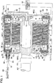
- FIG. 1 is a sectional view taken along a rotary shaft A of the rotary electric machine M according to this embodiment.
- the stator S and a rotor R are housed in a space formed by a case main body MC1 and a cover MC2 covering an opening portion of the case main body MC1, and the stator S is fixed to the case main body MC1.
- case main body MC1 and the cover MC2 correspond to a case for housing the rotary electric machine M, and therefore, when there is no need to differentiate between the case main body MC1 and the cover MC2 in the following description, they will be referred to together as a case MC1, MC2.
- the rotary electric machine M obtains rotary power through an electromagnetic effect between the coil C and a permanent magnet (not shown).
- This acquisition of rotary power is a well-known technique, and therefore description of the technique will be omitted herein. It is assumed in this embodiment that the coil C is provided in the stator S and the permanent magnet is provided in the rotor R.
- a cooling liquid to be described below corresponds to a cooling medium in the claims of the present application.
- Typical cooling oil suitable for cooling the rotary electric machine M is preferably used as the cooling liquid, but the cooling liquid is not limited thereto.
- the rotor R is held on the rotary shaft A, and the rotary shaft A is supported via a support bearing BRG to be rotatable relative to the case main body MC1 and the cover MC2.
- a plurality of permanent magnets (not shown) is disposed on the rotor R.
- the rotor R includes a plurality of flow passages R1 for circulating the cooling liquid through a rotor core. By circulating the cooling liquid through the flow passages R1 in the rotor core, the permanent magnets can be cooled.
- Cooling liquid supplied to a cooling liquid supply port in that is provided in a central portion of the rotary shaft A is supplied to the flow passages R1 via a first flow passage 11 by centrifugal force generated upon rotation of the rotary shaft A, in other words, rotation of the rotor R, and then circulated through the flow passages R1.
- a connecting portion A1 is provided on one end portion of the rotary shaft A so that the rotary shaft A is connected to a power transmission shaft A2 via the connecting portion A1, and thus a driving force generated by the rotary electric machine M can be output to the outside of the rotary electric machine M.
- the rotary electric machine M functions as an electric motor.
- the rotary electric machine M can also function as a generator for generating power using a driving force transmitted to the rotary electric machine M from the outside of the rotary electric machine M.
- the stator S includes a stator core SC fixed to the case main body MC1, and a coil end CE of the coil C wound around the stator core SC is positioned on an outer side of each of the two axial ends of the stator core SC.
- the stator core SC is formed by stacking a large number of ring-shaped steel plates p in an axial direction of the rotary shaft A.
- the coil C is formed by winding lead wires around the stator core SC and fixed into shape in an insulated condition created by impregnating the coil C with an insulating varnish for insulating the lead wires from each other.
- an insulating varnish for insulating the lead wires from each other.
- the structure of the rotary electric machine M according to the present invention has been schematically described above.
- the cooling unit 1 provided in the rotary electric machine M will be hereinafter described.
- the rotary electric machine M includes the first flow passage 11 through which cooling liquid for cooling the permanent magnets flows, and a second flow passage 12 through which cooling liquid for cooling the coil C flows. Cooling liquid is supplied to the first flow passage 11 by a hydraulic control unit 10 via an in-case oil passage 13 provided in the case MC1, MC2 and the aforementioned cooling liquid supply port in.
- the hydraulic control unit 10 preferably includes a pump that can supply the cooling liquid.
- a control valve that can set a pressure and a flow rate of the cooling liquid may be provided in each of the first flow passage 11, the second flow passage 12, and the in-case oil passage 13. As shown in FIG.
- the first flow passage 11 is formed to extend from the cooling liquid supply port in to the flow passages R1 in the rotor core.
- the second flow passage 12 is connected to a cooling liquid inlet port 60 provided in the cooling unit 1 covering the coil end CE of the stator S, which is fixed to an inner surface of the case main body MC1.
- the cooling unit 1 is mainly constituted by an oil jacket that covers the coil C in order to cool the coil end CE. Therefore, in the following description, the cooling unit 1 will be described as an oil jacket 1.
- the coil end CE is positioned on the outer side of each of the two axial ends of the stator core SC. Accordingly, the oil jacket 1 is disposed to cover the coil end CE positioned on the outer side of each of the two axial ends of the stator core SC. Note that when it is necessary to differentiate between the oil jackets 1, the oil jackets 1 will be referred to as a first oil jacket 1a and a second oil jacket 1b for convenience.
- the rotary electric machine M includes the oil jackets 1 for cooling the respective coil ends CE.
- FIG. 2 is a partially enlarged view showing a portion of the coil end CE and the oil jacket 1 shown in FIG. 1 to clarify the constitution of the oil jacket 1.
- the oil jacket 1 includes an outer periphery cooling portion 20 that is disposed around an outer peripheral surface 3a of the coil end CE and has a plurality of injection holes ih for injecting the cooling liquid onto the outer peripheral surface 3a of the coil end CE, an end surface cooling portion 30 that is disposed around an axial end surface 3b of the coil end CE and has a plurality of injection holes ih for injecting the cooling liquid onto the axial end surface 3b of the coil end CE, and an inner periphery cooling portion 40 that is disposed around an inner peripheral surface 3c of the coil end CE and has a plurality of injection holes ih for injecting the cooling liquid onto the inner peripheral surface 3c of the coil end CE.
- the outer peripheral surface 3a of the coil end CE is the surface that faces radially outward.
- the axial end surface 3b of the coil end CE is the surface that faces one end in the axial direction of the rotary shaft A.
- the inner peripheral surface 3c of the coil end CE is the surface that faces radially inward.
- a plurality of the injection holes ih is formed in each of the outer periphery cooling portion 20, the end surface cooling portion 30, and the inner periphery cooling portion 40.
- the injection holes ih are formed to face the respective directions of the outer peripheral surface 3a, the axial end surface 3b, and the inner peripheral surface 3c such that the cooling liquid supplied from the aforementioned hydraulic control unit 10 via the second flow passage 12 can be injected toward the outer peripheral surface 3a, the axial end surface 3b, and the inner peripheral surface 3c, respectively.
- the outer periphery cooling portion 20 and the end surface cooling portion 30 include a cooling medium flow passage 50 through which the cooling liquid flows so as to be supplied in common to the plurality of injection holes ih.
- the inner periphery cooling portion 40 there also provided the cooling medium flow passage 50 through which the cooling liquid flows so as to be supplied in common to the plurality of injection holes ih. Accordingly, the hollow cooling medium flow passage 50 through which the cooling liquid can flow is formed in the outer periphery cooling portion 20, the end surface cooling portion 30, and the inner periphery cooling portion 40.
- the plurality of injection holes ih is formed such that the cooling medium is supplied in common from the cooling medium flow passage 50.
- the outer periphery cooling portion 20 and the end surface cooling portion 30 are formed integrally with each other such that respective portions of the cooling medium flow passage 50 in the outer periphery cooling portion 20 and the end surface cooling portion 30 communicate with each other.
- the inner periphery cooling portion 40 is formed integrally with the outer periphery cooling portion 20 and the end surface cooling portion 30, and a portion of the cooling medium flow passage 50 in the inner periphery cooling portion 40 is formed integrally with the portions of the cooling medium flow passage 50 in the outer periphery cooling portion 20 and the end surface cooling portion 30 so as to communicate with each other.
- the cooling liquid flowing through the cooling medium flow passage 50 is injected onto the respective surfaces of the coil end CE through the plurality of injection holes ih formed in the cooling medium flow passage 50.
- the cooling liquid that flows through the portion of the cooling medium flow passage 50 in the outer periphery cooling portion 20 is injected onto the outer peripheral surface 3a of the coil end CE, as shown by a broken line d in FIG. 2 .
- the cooling liquid that flows through the portion of the cooling medium flow passage 50 in the end surface cooling portion 30 is injected onto the axial end surface 3b of the coil end CE, as shown by a broken line e in FIG. 2 .
- the cooling liquid that flows through the portion of the cooling medium flow passage 50 in the inner periphery cooling portion 40 is injected onto the inner peripheral surface 3c of the coil end CE, as shown by a broken line f in FIG. 2 .
- the rotary electric machine M according to the present invention is a three-phase drive rotary electric machine M.
- the coil C is also formed in a three-phase constitution (U phase, V phase, W phase).
- the lead wires of the respective phases are arranged in sequence from the inner peripheral surface 3c to the outer peripheral surface 3a of the coil end CE. Since the coil C of the rotary electric machine M according to this embodiment is formed in this manner, the coils C of respective phases can all be cooled by injecting the cooling liquid onto the axial end surface 3b of the coil end CE, in particular, as shown by the broken line e. Therefore, in this embodiment, the rotary electric machine M according to the present invention can cool the coil end CE efficiently by injecting the cooling liquid onto the coil end CE from three directions.
- a rotor side end portion 41 of the inner periphery cooling portion 40 is formed distant from an axial end surface 70 of the rotor R supported rotatably on a radially inner side of the stator S.
- the rotor R is formed with the plurality of flow passages R1 for circulating the cooling liquid through the rotor core. After flowing through the flow passages R1 in the rotor core, the cooling liquid is injected onto the inner peripheral surface 3c of the coil end CE from the flow passages R1 in the rotor core by a centrifugal force generated when the rotary shaft A rotates, as shown by a broken line g.
- the inner peripheral surface 3c of the coil end CE can also be cooled from the flow passages on the rotor R side, enabling a further improvement in the cooling effect.
- the rotor side end portion 41 of the oil jacket 1 and the axial end surface 70 of the rotor R are formed distant from each other so as to ensure that the cooling liquid can be injected from the flow passage R1 in the rotor core onto the coil end CE.
- the oil jacket 1 is formed from an insulating material and disposed in an insulating space between the case MC1, MC2 housing the stator S and the coil end CE.
- the lead wires forming the coil C are wound around the coil end CE.
- the lead wires are impregnated with the insulating varnish for insulating the lead wires from each other, and fixed into shape in an insulated condition.
- a large current flows through the lead wires, and the case MC1, MC2 of the rotary electric machine M may be formed from a conductor.
- an insulating space is formed at a predetermined insulating distance between the coil end CE and the case MC1, MC2, thereby securing insulation between the coil end CE and the case MC1, MC2.
- the oil jacket 1 according to the present invention is formed from an insulating material in order to secure the insulation.
- resin may be used favorably as the insulating material.
- the oil jacket 1 is formed from resin or the like and disposed in the insulating space between the coil end CE and the case main body MC1 and cover MC2 housing the stator S. Since the oil jacket 1 is disposed in the insulating space that preexists in the case MC1, MC2, there is no need to provide a new space for disposing the oil jacket 1. As a result, an increase in the size of the rotary electric machine M can be prevented.
- the oil jacket 1 is positioned such that the outer periphery cooling portion 20 and the end surface cooling portion 30 are in surface contact with an inner wall of the case MC1, MC2.
- surface contact indicates a state where at least the surfaces are in contact with each other.
- the outer periphery cooling portion 20 is positioned such that an outer surface thereof is in surface contact with an inner wall MC I a of the case main body MC1
- the end surface cooling portion 30 is positioned such that an outer surface thereof is in surface contact with an inner wall MC2a of the cover MC2.
- the oil jacket 1 is structured to cover the coil end CE of the stator S from outside in the axial direction of the rotary shaft A.
- the rotary electric machine M is provided with the pair of oil jackets 1 that includes the first oil jacket 1a and the second oil jacket 1b.
- the first oil jacket 1a corresponds to the oil jacket 1 disposed on the cover MC2 side in FIG. 1
- the second oil jacket 1b corresponds to the oil jacket 1 disposed on the connecting portion A1 side in FIG. 1 .
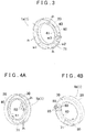
- FIG. 3 is a perspective view of the first oil jacket 1a.
- the first oil jacket 1a includes the outer periphery cooling portion 20, the end surface cooling portion 30, and the inner periphery cooling portion 40.
- the plurality of the injection holes ih for injecting the cooling liquid onto the respective surfaces of the coil end CE is formed in each of the cooling portions 20, 30 and 40.
- the outer periphery cooling portion 20 is cylindrically formed covering the outer peripheral surface 3a of the coil end CE. More specifically, the outer periphery cooling portion 20 is cylindrically formed having a width w1 so that the outer peripheral surface 3a of the coil end CE can be covered at a predetermined width.
- the outer periphery cooling portion 20 is formed to have the width w1
- the injection holes ih can be disposed in desired circumferential and axial positions in the outer peripheral surface 3a of the coil end CE.
- the entire outer peripheral surface 3a of the coil end CE can be cooled, and therefore the coil end CE can be cooled effectively.
- the end surface cooling portion 30 is formed in an annular disc shape covering the axial end surface 3b of the coil end CE. More specifically, the end surface cooling portion 30 is formed in an annular disc shape having a width w2 so that the axial end surface 3b of the coil end CE can be covered at a predetermined width. Furthermore, since the end surface cooling portion 30 is formed to have the width w2, the injection holes ih can be disposed in desired circumferential and radial positions in the axial end surface 3b of the coil end CE. Hence, the entire axial end surface 3b of the coil end CE can be cooled, and therefore the coil end CE can be cooled effectively.
- the inner periphery cooling portion 40 is cylindrically formed covering the inner peripheral surface 3c of the coil end CE. More specifically, the inner periphery cooling portion 40 is cylindrically formed having a width w3 so that the inner peripheral surface 3c of the coil end CE can be covered at a predetermined width. Furthermore, since the inner periphery cooling portion 40 is formed to have the width w3, the injection holes ih can be disposed in desired circumferential and axial positions in the inner peripheral surface 3c of the coil end CE. Hence, the entire inner peripheral surface 3b of the coil end CE can be cooled, and therefore the coil end CE can be cooled effectively.
- the oil jacket 1 constituted by the outer periphery cooling portion 20, the end surface cooling portion 30 and the inner periphery cooling portion 40 includes a radial cross-section formed in a U shape, as shown in FIG. 2 .
- the oil jacket 1 can cover the outer peripheral surface 3a, the axial end surface 3b, and the inner peripheral surface 3c of the coil end CE integrally.
- the axial end surface 3b corresponds to a side face of the coil end CE. Therefore, the injection holes ih can be disposed in desired positions over the entire surface of the coil end CE, and as a result, the entire coil end CE can be cooled effectively.
- the oil jacket 1 for cooling all of the outer peripheral surface 3a, the axial end surface 3b, and the inner peripheral surface 3c of the coil end CE can be formed integrally, and therefore the size of the rotary electric machine M does not increase.
- the first oil jacket 1a is also formed with the cooling liquid inlet port 60 through which the cooling liquid flows in and a cooling liquid outlet port 71 through which the cooling liquid flows out. As shown in FIG. 1 , one end of the cooling liquid inlet port 60 communicates with the second flow passage 12 and the other end communicates with the cooling medium flow passage 50.
- the plurality of the injection holes ih is formed in the cooling medium flow passage 50, as described above. Therefore, the first oil jacket 1a can cool the coil end CE by injecting cooling liquid supplied from the cooling liquid inlet port 60 onto the coil end CE.
- the cooling liquid injected onto the coil end CE moves downward in a gravity direction within the case MC1, MC2.
- the first oil jacket 1a is in surface contact with the case MC1, MC2, and therefore the cooling liquid that moves downward in the gravity direction moves into a gap between the outer peripheral surface 3a of the coil end CE and the outer periphery cooling portion 20.
- the cooling liquid outlet port 71 through which the cooling liquid flows out is formed in the first oil jacket 1a to discharge the cooling liquid from the first oil jacket 1a so that the cooling liquid can circulate.
- the cooling liquid outlet port 71 is formed by partially cutting away the outer periphery cooling portion 20.
- the cooling liquid that flows out through the cooling liquid outlet port 71 passes through a flow passage, not shown in the drawing, and accumulates in a cooling liquid storage portion.
- the cooling liquid which is warmed by heat drawn from the coil end CE, is then circulated to and cooled by an oil cooler, and then reused to cool the rotary electric machine M including the coil end CE.
- FIG. 4A is a perspective view showing the second oil jacket 1b from the side covering the coil end CE.
- FIG. 4B is a perspective view showing the second oil jacket 1b from the side in surface contact with the case main body MC1.
- the second oil jacket 1b includes the outer periphery cooling portion 20, the end surface cooling portion 30, and the inner periphery cooling portion 40, similarly to the first oil jacket la.
- the plurality of injection holes ih for injecting cooling liquid onto the respective surfaces of the coil end CE is formed in each of the cooling portions 20, 30 and 40.
- the second oil jacket 1b is also formed with the cooling liquid inlet port 60 through which the cooling liquid flows in and the cooling liquid outlet port 71 through which the cooling liquid flows out.
- the cooling liquid outlet port 71 of the first oil jacket 1a is formed in the outer periphery cooling portion 20.
- the cooling liquid outlet port 71 of the second oil jacket 1b is formed by providing an opening portion in a portion of the end surface cooling portion 30. Even when the cooling liquid outlet port 71 is provided in the end surface cooling portion 30 in this manner, the cooling liquid that moves between the coil end CE and the outer periphery cooling portion 20 can accumulate in the cooling liquid storage portion through a flow passage not shown in the drawings.
- the end surface cooling portion 30 of the second oil jacket 1b includes a terminal block 80 for supporting a terminal 81 (see FIG. 1 ) connected to the coil end CE.
- the terminal block 80 is formed from three cylindrical members, as shown in FIG. 4 .
- the rotary electric machine M according to the present invention is a three-phase drive rotary electric machine M. Therefore, the coil C is also constituted by three phases, namely a U phase, a V phase, and a W phase.
- a lead wire end portion Ca of the lead wire of each phase is connected to the terminal 81 in order to form a connection with an inverter unit 90 that conducts a current for driving the rotary electric machine M to the coil C.
- This connection is preferably formed by bundling together and crimping the lead wire end portions Ca of the respective phases.
- the terminal 81 is supported by the terminal block 80.
- the case main body MC1 housing the stator S includes an outside communication hole 82 that communicates with the outside.
- the terminal block 80 is supported in the outside communication hole 82 via a first seal member 83, and the terminal 81 is supported on the terminal block 80 via a second seal member 84.
- the outside communication hole 82 is formed in the case main body MC1 to connect the inside of the case main body MC1 to the outside.
- the outside communication hole 82 is a round hole penetrating a cylindrical portion formed to project outward in the axial direction from the case main body MC1.
- the terminal block 80 of the second oil jacket 1b is inserted into the outside communication hole 82 so as to be supported in the outside communication hole 82.
- the first seal member 83 is provided between an inner peripheral surface of the outside communication hole 82 and an outer peripheral surface of the terminal block 80 to secure liquid-tightness between the inside and the outside the case main body MC1.
- the first seal member 83 is preferably an O-ring, for example.
- the terminal block 80 is formed with a hole 85 to connect the inside and the outside of the oil jacket 1b.
- the second seal member 84 is provided between an inner peripheral surface of the terminal block 80 and an outer peripheral surface of the terminal 81 to secure liquid-tightness between the inside and the outside of the oil jacket 1b.
- the second seal member 84 is preferably an O-ring, for example, similarly to the first seal member 83.
- the oil jacket 1 injects cooling liquid onto the outer peripheral surface 3a, the axial end surface 3b, and the inner peripheral surface 3c of the coil end CE, and therefore the coil end CE can be cooled effectively.
- the cooling liquid onto the axial end surface 3b of the coil end CE
- the coils C of the respective phases which are arranged in sequence from the inner peripheral surface 3c to the outer peripheral surface 3b of the coil end CE, can all be cooled by the cooling liquid.
- the injection holes ih can be provided to face each of the outer peripheral surface 3a, the axial end surface 3b, and the inner peripheral surface 3c of the coil end CE, and therefore the layout freedom of the injection holes ih can be increased in comparison with the related art.
- the shape of the oil jacket 1 is designed to fit the shape of the coil end CE so that an insulating space can be disposed between the case MC1, MC2 and the coil end CE, and therefore increases in the size of the rotary electric machine M can be prevented.
- the present invention may be used in various well-known rotary electric machines including a stator having a coil and a cooling unit for cooling a coil end of the coil, which projects in an axial direction of the stator.
Landscapes
- Engineering & Computer Science (AREA)
- Power Engineering (AREA)
- Motor Or Generator Cooling System (AREA)
- Iron Core Of Rotating Electric Machines (AREA)
Claims (14)
- Elektrische Drehmaschine (M) mit einem Stator (S), der eine Spule (C) und eine Kühleinheit (1) zum Kühlen eines Spulenendes (CE) der Spule, das in einer axialen Richtung des Stators vorsteht, umfasst, wobei
die Kühleinheit (1) umfasst:einen Außenumfangskühlabschnitt (20), der entlang einer Außenumfangsoberfläche (3a) des Spulenendes angeordnet ist und mehrere Einspritzlöcher (ih) zum Einspritzen eines Kühlmediums auf die Außenumfangsoberfläche umfasst,dadurch gekennzeichnet, dass die Kühleinheit (1) auch einen Endoberflächenkühlabschnitt (30) umfasst, der entlang einer axialen Endoberfläche (36) des Spulenendes angeordnet ist und mehrere Einspritzlöcher (ih) zum Einspritzen des Kühlmediums auf die axiale Endoberfläche umfasst, und dadurch, dass die Kühleinheit (1) aus einem Isoliermaterial ausgebildet ist und in einem Isolierraum zwischen einem Gehäuse (MC1, MC2), das den Stator (S) einhaust, und dem Spulenende (CE) angeordnet ist. - Elektrische Drehmaschine nach Anspruch 1, wobei der Außenumfangskühlabschnitt und der Endoberflächenkühlabschnitt einen Kühlmediumströmungskanal (50), durch den das Kühlmedium strömt, um den mehreren Einspritzlöchern gemeinsam zugeführt zu werden, umfassen.
- Elektrische Drehmaschine nach Anspruch 2, wobei der Außenumfangskühlabschnitt und der Endoberflächenkühlabschnitt einstückig ausgebildet sind, derart, dass jeweilige Abschnitte des Kühlmediumströmungskanals in dem Außenumfangskühlabschnitt und dem Endoberflächenkühlabschnitt miteinander kommunizieren.
- Elektrische Drehmaschine nach einem beliebigen der Ansprüche 1 bis 3, wobei der Außenumfangskühlabschnitt zylindrisch ausgebildet ist und die Außenumfangsoberfläche des Spulenendes bedeckt.
- Elektrische Drehmaschine nach einem beliebigen der Ansprüche 1 bis 4, wobei der Endoberflächenkühlabschnitt ringscheibenförmig ausgebildet ist und die axiale Endoberfläche des Spulenendes bedeckt.
- Elektrische Drehmaschine nach einem beliebigen der Ansprüche 1 bis 5, wobei die Kühleinheit einen U-förmig ausgebildeten radialen Querschnitt umfasst, um so die Außenumfangsoberfläche, die axiale Endoberfläche und eine Innenumfangsoberfläche (3c) des Spulenendes einstückig zu bedecken.
- Elektrische Drehmaschine nach einem beliebigen der Ansprüche 1 bis 6, wobei die Kühleinheit ferner einen Innenumfangskühlabschnitt (40) umfasst, der entlang der Innenumfangsoberfläche des Spulenendes angeordnet ist und mehrere Einspritzlöcher (ih) zum Einspritzen des Kühlmediums auf die Innenumfangsoberfläche des Spulenendes umfasst.
- Elektrische Drehmaschine nach Anspruch 7, wobei der Innenumfangskühlabschnitt einstückig mit dem Außenumfangskühlabschnitt und dem Endoberflächenkühlabschnitt ausgebildet ist.
- Elektrische Drehmaschine nach Anspruch 7 oder 8, ferner umfassend einen Rotor (R), der auf einer radial inneren Seite des Stators drehbar gelagert ist, wobei
ein Rotorseitenendabschnitt (41) des Innenumfangskühlabschnitts von einer axialen Endoberfläche (70) des Rotors entfernt ausgebildet ist. - Elektrische Drehmaschine nach einem beliebigen der Ansprüche 7 bis 9, wobei der Innenumfangskühlabschnitt zylindrisch ausgebildet ist und die Innenumfangsoberfläche des Spulenendes bedeckt.
- Elektrische Drehmaschine nach einem beliebigen der Ansprüche 1 bis 10, wobei die Kühleinheit derart angeordnet ist, dass der Außenumfangskühlabschnitt und der Endoberflächenkühlabschnitt mit einer Innenwand des Gehäuses in Oberflächenkontakt stehen.
- Elektrische Drehmaschine nach einem beliebigen der Ansprüche 1 bis 11, wobei der Endoberflächenkühlabschnitt einen Klemmenblock (80) zum Tragen einer Klemme (81), die mit der Spule verbunden ist, umfasst.
- Elektrische Drehmaschine nach Anspruch 12, wobei
das Gehäuse, das den Stator einhaust, ein Außenkommunikationsloch (82) umfasst, das mit dem Äußeren kommuniziert,
der Klemmenblock über ein erstes Dichtungselement (83) in dem Außenkommunikationsloch gelagert ist und
die Klemme über ein zweites Dichtungselement (84) durch den Klemmenblock gelagert ist. - Elektrische Drehmaschine nach einem beliebigen der Ansprüche 1 bis 3, wobei
der Außenumfangskühlabschnitt zylindrisch ausgebildet ist und die Außenumfangsoberfläche des Spulenendes bedeckt,
der Endoberflächenkühlabschnitt ringscheibenförmig ausgebildet ist und die axiale Endoberfläche des Spulenendes bedeckt und
die Kühleinheit einen radialen Querschnitt umfasst, der L-förmig ausgebildet ist, um so die Außenumfangsoberfläche und die axiale Endoberfläche des Spulenendes einstückig zu bedecken.
Applications Claiming Priority (2)
| Application Number | Priority Date | Filing Date | Title |
|---|---|---|---|
| JP2008214642A JP5088577B2 (ja) | 2008-08-22 | 2008-08-22 | 回転電機 |
| PCT/JP2009/064458 WO2010021327A1 (ja) | 2008-08-22 | 2009-08-18 | 回転電機 |
Publications (3)
| Publication Number | Publication Date |
|---|---|
| EP2242164A1 EP2242164A1 (de) | 2010-10-20 |
| EP2242164A4 EP2242164A4 (de) | 2016-06-08 |
| EP2242164B1 true EP2242164B1 (de) | 2020-02-26 |
Family
ID=41695695
Family Applications (1)
| Application Number | Title | Priority Date | Filing Date |
|---|---|---|---|
| EP09808263.9A Active EP2242164B1 (de) | 2008-08-22 | 2009-08-18 | Elektrische drehmaschine |
Country Status (5)
| Country | Link |
|---|---|
| US (1) | US7952240B2 (de) |
| EP (1) | EP2242164B1 (de) |
| JP (1) | JP5088577B2 (de) |
| CN (1) | CN101953052B (de) |
| WO (1) | WO2010021327A1 (de) |
Cited By (1)
| Publication number | Priority date | Publication date | Assignee | Title |
|---|---|---|---|---|
| EP4387061A1 (de) * | 2022-12-12 | 2024-06-19 | Polestar Performance AB | Kühlmediumverteilungsvorrichtung für einen elektromotor und elektromotor |
Families Citing this family (122)
| Publication number | Priority date | Publication date | Assignee | Title |
|---|---|---|---|---|
| JP4919106B2 (ja) * | 2009-01-15 | 2012-04-18 | アイシン・エィ・ダブリュ株式会社 | ステータ |
| DE102009045844B4 (de) | 2009-10-20 | 2024-04-04 | Robert Bosch Gmbh | Elektromaschine |
| US9112391B2 (en) * | 2010-04-23 | 2015-08-18 | Toyota Jidosha Kabushiki Kaisha | Motor cooling device having flow rate adjusting means for a coil end cover |
| US8536813B2 (en) | 2010-05-19 | 2013-09-17 | The Invention Science Fund I Llc | Motor with rotor-mounted control circuitry |
| US8466649B2 (en) * | 2010-05-19 | 2013-06-18 | The Invention Science Fund I Llc | Heat removal from motor components |
| US8963384B2 (en) | 2010-06-21 | 2015-02-24 | Nidec Motor Corporation | Electric motor assemblies including stator and/or rotor cooling |
| JP5575055B2 (ja) * | 2010-06-24 | 2014-08-20 | 株式会社日本自動車部品総合研究所 | 回転電機 |
| CN102343798B (zh) * | 2010-07-30 | 2014-04-23 | 上海华普汽车有限公司 | 适用于混合动力汽车的电机 |
| JP5471955B2 (ja) * | 2010-08-06 | 2014-04-16 | アイシン・エィ・ダブリュ株式会社 | 回転電機及び車両用駆動装置 |
| US8508086B2 (en) * | 2010-08-30 | 2013-08-13 | Toyota Jidosha Kabushiki Kaisha | Cooling structure of rotating electrical machine |
| US8378550B2 (en) | 2010-09-10 | 2013-02-19 | Remy Technologies, L.L.C. | Electric machine including a stator having a stator sleeve and method of cooling a stator |
| US12328346B2 (en) | 2010-09-13 | 2025-06-10 | Jeffrey W. Mankoff | Modifying signal associations in complex computing networks |
| US8970073B2 (en) * | 2010-10-19 | 2015-03-03 | Toyota Jidosha Kabushiki Kaisha | Cooling structure for rotary electric machine |
| JP5134064B2 (ja) * | 2010-11-18 | 2013-01-30 | トヨタ自動車株式会社 | 回転電機 |
| US8497608B2 (en) * | 2011-01-28 | 2013-07-30 | Remy Technologies, Llc | Electric machine cooling system and method |
| JP5274613B2 (ja) * | 2011-04-21 | 2013-08-28 | 三菱電機株式会社 | 外被冷却形回転電機およびそれに用いられるケーシング |
| JP5957803B2 (ja) * | 2011-05-17 | 2016-07-27 | アイシン精機株式会社 | 回転電機 |
| JP5734765B2 (ja) * | 2011-06-24 | 2015-06-17 | トヨタ自動車株式会社 | 回転電機の冷却構造 |
| US9373984B2 (en) * | 2011-06-29 | 2016-06-21 | General Electric Company | Electrical machine |
| JP2013014302A (ja) * | 2011-07-02 | 2013-01-24 | Tadashi Takano | 電気走行可能な自動車 |
| US9041260B2 (en) * | 2011-07-08 | 2015-05-26 | Remy Technologies, Llc | Cooling system and method for an electronic machine |
| JP5672193B2 (ja) * | 2011-08-08 | 2015-02-18 | トヨタ自動車株式会社 | 回転電機 |
| US9048710B2 (en) * | 2011-08-29 | 2015-06-02 | Remy Technologies, Llc | Electric machine module cooling system and method |
| US8975792B2 (en) * | 2011-09-13 | 2015-03-10 | Remy Technologies, Llc | Electric machine module cooling system and method |
| US9331553B2 (en) | 2011-09-19 | 2016-05-03 | Georgia Tech Research Corporation | Systems and methods for direct winding cooling of electric machines |
| US10886819B2 (en) | 2011-09-19 | 2021-01-05 | J. Rhett Mayor | Electric machine with direct winding heat exchanger |
| US20130147289A1 (en) * | 2011-12-08 | 2013-06-13 | Remy Technologies, Llc | Electric machine module cooling system and method |
| JP6194319B2 (ja) * | 2011-12-31 | 2017-09-06 | ロトニックス ホンコン リミテッド | 電気機械式フライホイール格納システム |
| CN102664476A (zh) * | 2012-05-25 | 2012-09-12 | 江苏常牵庞巴迪牵引系统有限公司 | 电机定子线圈的散热结构 |
| US8896167B2 (en) * | 2012-05-25 | 2014-11-25 | Deere & Company | Electric machine rotor cooling method |
| US20140015355A1 (en) * | 2012-07-12 | 2014-01-16 | Deere & Company | Electric Machine Cooling Arrangement And Method |
| US9657747B2 (en) | 2012-09-06 | 2017-05-23 | Carrier Corporation | Motor rotor and air gap cooling |
| JP5714545B2 (ja) * | 2012-09-18 | 2015-05-07 | トヨタ自動車株式会社 | 電動機の冷却装置 |
| SE537090C2 (sv) | 2012-11-07 | 2015-01-07 | BAE Systems Hägglunds Aktiebolag | Förfarande och anordning för vätskekylning av en elmotor |
| JP5604498B2 (ja) * | 2012-11-08 | 2014-10-08 | 本田技研工業株式会社 | 回転電機の冷却構造体 |
| JP5998871B2 (ja) * | 2012-11-22 | 2016-09-28 | 株式会社デンソー | 回転電機のステータ |
| KR101995849B1 (ko) * | 2012-12-17 | 2019-07-03 | 엘지이노텍 주식회사 | 냉각유체 공급 회수 장치 및 이를 구비한 전동기 |
| US9929614B2 (en) * | 2013-07-02 | 2018-03-27 | Nidec Corporation | Motor with integrated slot liner and bobbin with guides for conductor coils |
| JP5812047B2 (ja) * | 2013-07-05 | 2015-11-11 | トヨタ自動車株式会社 | 回転電機 |
| CN203589922U (zh) * | 2013-10-09 | 2014-05-07 | 富鼎电子科技(嘉善)有限公司 | 马达 |
| US10439477B2 (en) * | 2014-01-31 | 2019-10-08 | Tesla, Inc. | Pressurized and gravity-fed liquid cooling of electric motor |
| US9837868B2 (en) * | 2014-02-28 | 2017-12-05 | Ge Aviation Systems Llc | Rotor assembly for an electric machine |
| JP6221947B2 (ja) * | 2014-06-04 | 2017-11-01 | 株式会社デンソー | 回転電機 |
| WO2016044570A1 (en) * | 2014-09-18 | 2016-03-24 | Prippel Technologies, Llc | Electric machine end turn cooling apparatus |
| FR3026575B1 (fr) * | 2014-09-30 | 2018-01-12 | Renault S.A.S | Ensemble de refroidissement pour moteur electrique a bobinage dentaire |
| US9793782B2 (en) * | 2014-12-12 | 2017-10-17 | Hamilton Sundstrand Corporation | Electrical machine with reduced windage |
| ES1135742Y (es) * | 2015-01-14 | 2015-04-27 | Coprecitec Sl | Bomba eléctrica |
| KR101700769B1 (ko) * | 2015-07-24 | 2017-01-31 | 엘지전자 주식회사 | 전동기 및 그의 제조방법 |
| JP6703813B2 (ja) * | 2015-08-06 | 2020-06-03 | 国立大学法人横浜国立大学 | 冷却装置、およびモータ |
| US10468923B2 (en) * | 2015-09-02 | 2019-11-05 | Nidec Motor Corporation | Motor having split spray ring for cooling end turns |
| JP6226938B2 (ja) * | 2015-11-24 | 2017-11-08 | 本田技研工業株式会社 | 回転電機 |
| US10008907B2 (en) * | 2016-03-17 | 2018-06-26 | Ford Global Technologies, Llc | Over mold with integrated insert to enhance heat transfer from an electric machine end winding |
| US10086538B2 (en) | 2016-03-17 | 2018-10-02 | Ford Global Technologies, Llc | Thermal management assembly for an electrified vehicle |
| US10038351B2 (en) | 2016-03-17 | 2018-07-31 | Ford Global Technologies, Llc | Thermal management assembly for an electrified vehicle |
| US10536055B2 (en) * | 2016-03-17 | 2020-01-14 | Ford Global Technologies, Llc | Thermal management assembly for an electrified vehicle |
| US10135319B2 (en) | 2016-03-17 | 2018-11-20 | Ford Global Technologies, Llc | Electric machine for vehicle |
| US10097066B2 (en) | 2016-03-17 | 2018-10-09 | Ford Global Technologies, Llc | Electric machine for vehicle |
| US10008908B2 (en) | 2016-03-17 | 2018-06-26 | Ford Global Technologies, Llc | Electric machine for vehicle |
| US10516320B2 (en) * | 2016-05-09 | 2019-12-24 | Borgwarner Inc. | Cooling system for an electric motor |
| FR3051298B1 (fr) * | 2016-05-13 | 2020-11-13 | Inst Vedecom | Flasque pour machine electrique |
| DE102016209752A1 (de) * | 2016-06-03 | 2017-12-07 | Continental Automotive Gmbh | Kühlung einer elektrischen Maschine |
| US10700579B2 (en) * | 2016-07-20 | 2020-06-30 | Ge Aviation Systems Llc | Method and assembly of a generator |
| JP6624025B2 (ja) * | 2016-11-28 | 2019-12-25 | トヨタ自動車株式会社 | 回転電機 |
| WO2018105143A1 (ja) * | 2016-12-05 | 2018-06-14 | 三菱電機株式会社 | 回転電機 |
| JP6227215B1 (ja) * | 2016-12-05 | 2017-11-08 | 三菱電機株式会社 | 回転電機 |
| JP6436200B1 (ja) * | 2017-08-25 | 2018-12-12 | 株式会社明電舎 | 回転電機の固定子の冷却構造 |
| KR102524307B1 (ko) * | 2017-11-13 | 2023-04-21 | 현대모비스 주식회사 | 모터 |
| DE102017220856A1 (de) * | 2017-11-22 | 2019-06-06 | Bayerische Motoren Werke Aktiengesellschaft | Kühlkappe für einen Stator einer elektrischen Maschine eines Kraftfahrzeugs, Stator sowie Kraftfahrzeug |
| US10749404B2 (en) * | 2018-01-12 | 2020-08-18 | Ford Global Technologies, Llc | Terminal connector assembly in overmolded single unit with coil end windings, temperature sensors, and cooling channel |
| DE102018000875B4 (de) * | 2018-02-02 | 2021-06-24 | Daimler Ag | Aktivteil für eine elektrische Maschine, insbesondere eines Kraftfahrzeugs |
| JP6621114B2 (ja) * | 2018-02-21 | 2019-12-18 | 本田技研工業株式会社 | 回転電機 |
| JP2019154111A (ja) * | 2018-03-01 | 2019-09-12 | 本田技研工業株式会社 | 回転電機 |
| JP7071845B2 (ja) * | 2018-03-02 | 2022-05-19 | 本田技研工業株式会社 | 回転電機 |
| CN110635622B (zh) * | 2018-08-31 | 2020-11-13 | 北京金风科创风电设备有限公司 | 风力发电机组、电磁装置及铁心的换热装置 |
| DE102018218731A1 (de) * | 2018-10-31 | 2020-04-30 | Thyssenkrupp Ag | Stator für eine elektrische Maschine, sowie elektrische Maschine |
| KR102122238B1 (ko) * | 2019-01-07 | 2020-06-26 | 엘지전자 주식회사 | 전동기 |
| JP7233966B2 (ja) * | 2019-02-28 | 2023-03-07 | 本田技研工業株式会社 | 回転電機 |
| JP2020150641A (ja) * | 2019-03-12 | 2020-09-17 | 本田技研工業株式会社 | 回転電機およびモータユニット |
| US10892668B2 (en) * | 2019-04-12 | 2021-01-12 | Ford Global Technologies, Llc | Cooling systems for cooling electric machines within electrified vehicles |
| JP7386062B2 (ja) * | 2019-05-13 | 2023-11-24 | アルプスアルパイン株式会社 | 振動発生装置 |
| DE102019113950A1 (de) * | 2019-05-24 | 2020-11-26 | Schaeffler Technologies AG & Co. KG | Elektrische Maschine |
| US11469647B2 (en) * | 2019-06-07 | 2022-10-11 | Borgwarner Inc. | Oil cooling system for a stator of an electric machine |
| FR3098047B1 (fr) * | 2019-06-28 | 2022-05-20 | Valeo Equip Electr Moteur | Piece bobinee pour une machine electrique tournante destinee a un vehicule automobile |
| CN112311152A (zh) * | 2019-07-31 | 2021-02-02 | 华擎机械工业股份有限公司 | 具有内部冷却机制的电机机械装置 |
| JP2021055613A (ja) * | 2019-09-30 | 2021-04-08 | ダイキン工業株式会社 | ターボ圧縮機 |
| JP7405559B2 (ja) * | 2019-10-25 | 2023-12-26 | ファナック株式会社 | 冷却管を備えた電動機のステータ |
| JP7346287B2 (ja) * | 2019-12-25 | 2023-09-19 | 株式会社クボタ | 液冷モータ及び液冷モータを用いた冷却装置 |
| EP4087092B1 (de) * | 2019-12-31 | 2025-11-19 | Zhejiang Pangood Power Technology Co., Ltd. | Motorkühlsystem, motorstator und scheibenläufermotor |
| DE102020103437A1 (de) * | 2020-02-11 | 2021-08-12 | Schaeffler Technologies AG & Co. KG | Elektrische Antriebseinrichtung und Antriebsanordnung |
| JP7057384B2 (ja) * | 2020-02-26 | 2022-04-19 | 本田技研工業株式会社 | 電動機冷却構造 |
| JP6958655B2 (ja) * | 2020-03-19 | 2021-11-02 | 株式会社明電舎 | 回転機 |
| JP7351412B2 (ja) * | 2020-04-10 | 2023-09-27 | 株式会社アイシン | 車両用駆動装置 |
| DE102020111217A1 (de) * | 2020-04-24 | 2021-10-28 | Gea Mechanical Equipment Gmbh | Separator mit Direktantrieb |
| KR102883770B1 (ko) * | 2020-06-05 | 2025-11-11 | 스미또모 베이크라이트 가부시키가이샤 | 회전 전기 및 회전 전기의 냉각 구조 |
| CN111884428B (zh) | 2020-06-28 | 2021-10-22 | 华为技术有限公司 | 电机、电机冷却系统及电动车 |
| JP7444042B2 (ja) * | 2020-12-16 | 2024-03-06 | トヨタ自動車株式会社 | 回転電機のステータおよびステータの冷却構造 |
| KR102843153B1 (ko) * | 2020-12-31 | 2025-08-05 | 현대자동차주식회사 | 냉각오일 분사 구조 |
| JP2022107336A (ja) * | 2021-01-08 | 2022-07-21 | トヨタ自動車株式会社 | モータの磁石油冷構造及びモータ |
| JP7501417B2 (ja) * | 2021-03-22 | 2024-06-18 | 株式会社アイシン | ロータ |
| FR3122052A1 (fr) * | 2021-04-15 | 2022-10-21 | Novares France | Moteur électrique agencé pour permettre une meilleure évacuation de la chaleur générée lors de son fonctionnement |
| DE102021112194A1 (de) | 2021-05-11 | 2022-11-17 | Bayerische Motoren Werke Aktiengesellschaft | Statoranordnung sowie elektrische Maschine für ein Kraftfahrzeug |
| CN113422473A (zh) * | 2021-05-14 | 2021-09-21 | 珠海格力电器股份有限公司 | 外圈喷油结构、驱动电机和新能源汽车 |
| CN113422475B (zh) * | 2021-05-14 | 2025-06-13 | 珠海格力电器股份有限公司 | 定子冷却结构、驱动电机和新能源汽车 |
| KR102540617B1 (ko) * | 2021-06-07 | 2023-06-07 | 주식회사 코렌스이엠 | 냉각 효율이 개선된 모터 |
| EP4160877A1 (de) * | 2021-10-04 | 2023-04-05 | Scania CV AB | Elektrische rotierende maschine und verfahren und fahrzeug mit einer elektrischen maschine |
| GB202116498D0 (en) * | 2021-11-16 | 2021-12-29 | Rolls Royce Plc | Electric machine |
| US12046955B2 (en) | 2022-02-15 | 2024-07-23 | Dana Automotive Systems Group, Llc | Methods and systems for cooling an electric machine |
| CN217769761U (zh) * | 2022-04-12 | 2022-11-08 | 宁德时代(上海)智能科技有限公司 | 喷环、定子组件、电机和电动车辆 |
| EP4507174A4 (de) * | 2022-04-12 | 2025-09-03 | Contemporary Amperex Intelligence Tech Shanghai Limited | Sprühring, motor und fahrzeug |
| US20240072603A1 (en) * | 2022-08-24 | 2024-02-29 | Honeywell International Inc. | Cooling end turns in high power density electric generators |
| US20240100936A1 (en) * | 2022-09-22 | 2024-03-28 | Dana Tm4 Inc. | Electric axle with direct rotor and head spray cooling |
| US12278540B2 (en) * | 2022-09-28 | 2025-04-15 | Honda Motor Co., Ltd. | Cooling structure of vertical motor |
| JP7848669B2 (ja) * | 2022-11-29 | 2026-04-21 | トヨタ自動車株式会社 | モータ |
| KR102866189B1 (ko) * | 2022-11-30 | 2025-10-01 | 주식회사 엔엠씨 | 모터 냉각 구조 |
| JP2024081472A (ja) * | 2022-12-06 | 2024-06-18 | トヨタ自動車株式会社 | モータ |
| CN118783684A (zh) * | 2023-04-10 | 2024-10-15 | 安徽威灵汽车部件有限公司 | 电机、动力总成和车辆 |
| US20240356390A1 (en) * | 2023-04-20 | 2024-10-24 | Aisin Corporation | Encapsulation receptacle for welded stator wire ends |
| CN118826383A (zh) * | 2023-04-21 | 2024-10-22 | 法雷奥新能源汽车德国有限责任公司 | 电机冷却布置、喷油环、电机和车辆 |
| US20250105698A1 (en) * | 2023-09-26 | 2025-03-27 | Solar Turbines Incorporated | Motor power axial penetrator for integrated motor machine |
| FR3157984A1 (fr) * | 2023-12-30 | 2025-07-04 | Valeo Eautomotive Germany Gmbh | Machine électrique tournante |
| JP2026035105A (ja) * | 2024-08-19 | 2026-03-04 | Astemo株式会社 | 回転電機 |
| CN119010461B (zh) * | 2024-10-24 | 2025-01-14 | 比亚迪股份有限公司 | 导流装置、电机、动力总成及车辆 |
Family Cites Families (15)
| Publication number | Priority date | Publication date | Assignee | Title |
|---|---|---|---|---|
| GB165806A (en) * | 1918-06-19 | 1921-07-11 | Vickers Ltd | Improvements in or relating to the cooling of dynamo electric machines |
| US2583804A (en) * | 1948-01-21 | 1952-01-29 | Smith Corp A O | Motor winding |
| US2873393A (en) * | 1957-03-28 | 1959-02-10 | Westinghouse Electric Corp | Dual-ventilation hydrogen-cooled generators |
| US3574325A (en) * | 1969-02-19 | 1971-04-13 | Gen Motors Corp | Braking system for electric motors |
| US3995181A (en) * | 1975-06-13 | 1976-11-30 | Sundstrand Corporation | Matrix for enhancing the flow of coolant through an alternator stator |
| JPS6430655U (de) * | 1987-08-11 | 1989-02-27 | ||
| JPH0810978B2 (ja) * | 1988-09-13 | 1996-01-31 | ファナック株式会社 | 液冷式電動機 |
| JPH02228230A (ja) * | 1989-02-27 | 1990-09-11 | Nippon Seiko Kk | モータ |
| JPH0727270A (ja) | 1993-07-09 | 1995-01-27 | Kurihara Sangyo Kk | パイプ継手 |
| JP2602410Y2 (ja) * | 1993-10-22 | 2000-01-17 | 神鋼電機株式会社 | 内部液冷式電動機の冷却構造 |
| CA2116900A1 (en) * | 1994-03-03 | 1995-09-04 | Carlo C. Di Pietro | Electric vehicle motor |
| JP3502210B2 (ja) * | 1995-11-28 | 2004-03-02 | 株式会社日平トヤマ | ビルトインモータ |
| JP4317483B2 (ja) * | 2004-04-22 | 2009-08-19 | 株式会社オートネットワーク技術研究所 | 機器用コネクタ |
| JP4687180B2 (ja) | 2005-03-25 | 2011-05-25 | 日産自動車株式会社 | モータジェネレータの冷却構造 |
| JP4857026B2 (ja) * | 2006-05-22 | 2012-01-18 | トヨタ自動車株式会社 | 車両用動力伝達装置の冷却装置 |
-
2008
- 2008-08-22 JP JP2008214642A patent/JP5088577B2/ja not_active Expired - Fee Related
-
2009
- 2009-07-28 US US12/458,943 patent/US7952240B2/en not_active Expired - Fee Related
- 2009-08-18 CN CN200980105594XA patent/CN101953052B/zh not_active Expired - Fee Related
- 2009-08-18 WO PCT/JP2009/064458 patent/WO2010021327A1/ja not_active Ceased
- 2009-08-18 EP EP09808263.9A patent/EP2242164B1/de active Active
Non-Patent Citations (1)
| Title |
|---|
| None * |
Cited By (1)
| Publication number | Priority date | Publication date | Assignee | Title |
|---|---|---|---|---|
| EP4387061A1 (de) * | 2022-12-12 | 2024-06-19 | Polestar Performance AB | Kühlmediumverteilungsvorrichtung für einen elektromotor und elektromotor |
Also Published As
| Publication number | Publication date |
|---|---|
| CN101953052A (zh) | 2011-01-19 |
| US7952240B2 (en) | 2011-05-31 |
| EP2242164A4 (de) | 2016-06-08 |
| WO2010021327A1 (ja) | 2010-02-25 |
| CN101953052B (zh) | 2013-08-07 |
| EP2242164A1 (de) | 2010-10-20 |
| US20100045125A1 (en) | 2010-02-25 |
| JP5088577B2 (ja) | 2012-12-05 |
| JP2010051130A (ja) | 2010-03-04 |
Similar Documents
| Publication | Publication Date | Title |
|---|---|---|
| US7952240B2 (en) | Rotary electric machine | |
| US8203240B2 (en) | Liquid cooled rotating electrical machine | |
| JP7071845B2 (ja) | 回転電機 | |
| KR102649706B1 (ko) | 모터 | |
| CN102714438B (zh) | 旋转电机用转子 | |
| EP2568574B1 (de) | Drehende dreiphasige elektrische Maschine und Herstellungsverfahren dafür | |
| US7786630B2 (en) | Spray cooled V-wedge for aerospace generator | |
| JP2019161752A (ja) | 回転電機のステータ | |
| CN102986120A (zh) | 绝缘体以及具备该绝缘体的定子和电机 | |
| JP5549857B2 (ja) | 回転電機用ロータ | |
| CN103999328A (zh) | 电机 | |
| US20150372568A1 (en) | Electrical machine with direct stator cooling | |
| CN110277859B (zh) | 旋转电机 | |
| US20220200367A1 (en) | Stator for electrical machines | |
| WO2023113993A1 (en) | Fluid cooled stator | |
| CN117795827A (zh) | 具有集成的绕组头冷却装置的转子和电机、制造方法和机动车 | |
| JP5788055B1 (ja) | 車両用回転電機 | |
| US20240120781A1 (en) | Stator cooling | |
| US7482725B2 (en) | System and method for direct liquid cooling of electric machines | |
| JP7243780B1 (ja) | 回転電機 | |
| JP5330860B2 (ja) | 回転電機 | |
| US12489327B2 (en) | Cooled rotor of an electric machine | |
| JP2023085032A (ja) | モータ | |
| US9362794B2 (en) | Stator winding comprising multiple phase windings | |
| US12614940B2 (en) | Cooling of high-power permanent magnet machine rotor |
Legal Events
| Date | Code | Title | Description |
|---|---|---|---|
| PUAI | Public reference made under article 153(3) epc to a published international application that has entered the european phase |
Free format text: ORIGINAL CODE: 0009012 |
|
| 17P | Request for examination filed |
Effective date: 20100805 |
|
| AK | Designated contracting states |
Kind code of ref document: A1 Designated state(s): AT BE BG CH CY CZ DE DK EE ES FI FR GB GR HR HU IE IS IT LI LT LU LV MC MK MT NL NO PL PT RO SE SI SK SM TR |
|
| AX | Request for extension of the european patent |
Extension state: AL BA RS |
|
| DAX | Request for extension of the european patent (deleted) | ||
| RA4 | Supplementary search report drawn up and despatched (corrected) |
Effective date: 20160511 |
|
| RIC1 | Information provided on ipc code assigned before grant |
Ipc: H02K 1/20 20060101AFI20160504BHEP Ipc: H02K 3/24 20060101ALI20160504BHEP Ipc: H02K 9/19 20060101ALI20160504BHEP |
|
| RIC1 | Information provided on ipc code assigned before grant |
Ipc: H02K 3/24 20060101ALI20161114BHEP Ipc: H02K 9/19 20060101ALI20161114BHEP Ipc: H02K 1/20 20060101AFI20161114BHEP |
|
| GRAP | Despatch of communication of intention to grant a patent |
Free format text: ORIGINAL CODE: EPIDOSNIGR1 |
|
| STAA | Information on the status of an ep patent application or granted ep patent |
Free format text: STATUS: GRANT OF PATENT IS INTENDED |
|
| INTG | Intention to grant announced |
Effective date: 20190925 |
|
| GRAS | Grant fee paid |
Free format text: ORIGINAL CODE: EPIDOSNIGR3 |
|
| GRAA | (expected) grant |
Free format text: ORIGINAL CODE: 0009210 |
|
| STAA | Information on the status of an ep patent application or granted ep patent |
Free format text: STATUS: THE PATENT HAS BEEN GRANTED |
|
| AK | Designated contracting states |
Kind code of ref document: B1 Designated state(s): AT BE BG CH CY CZ DE DK EE ES FI FR GB GR HR HU IE IS IT LI LT LU LV MC MK MT NL NO PL PT RO SE SI SK SM TR |
|
| REG | Reference to a national code |
Ref country code: GB Ref legal event code: FG4D |
|
| REG | Reference to a national code |
Ref country code: CH Ref legal event code: EP |
|
| REG | Reference to a national code |
Ref country code: AT Ref legal event code: REF Ref document number: 1238836 Country of ref document: AT Kind code of ref document: T Effective date: 20200315 |
|
| REG | Reference to a national code |
Ref country code: IE Ref legal event code: FG4D |
|
| REG | Reference to a national code |
Ref country code: DE Ref legal event code: R096 Ref document number: 602009061291 Country of ref document: DE |
|
| PG25 | Lapsed in a contracting state [announced via postgrant information from national office to epo] |
Ref country code: FI Free format text: LAPSE BECAUSE OF FAILURE TO SUBMIT A TRANSLATION OF THE DESCRIPTION OR TO PAY THE FEE WITHIN THE PRESCRIBED TIME-LIMIT Effective date: 20200226 Ref country code: NO Free format text: LAPSE BECAUSE OF FAILURE TO SUBMIT A TRANSLATION OF THE DESCRIPTION OR TO PAY THE FEE WITHIN THE PRESCRIBED TIME-LIMIT Effective date: 20200526 |
|
| REG | Reference to a national code |
Ref country code: NL Ref legal event code: MP Effective date: 20200226 |
|
| REG | Reference to a national code |
Ref country code: LT Ref legal event code: MG4D |
|
| PG25 | Lapsed in a contracting state [announced via postgrant information from national office to epo] |
Ref country code: GR Free format text: LAPSE BECAUSE OF FAILURE TO SUBMIT A TRANSLATION OF THE DESCRIPTION OR TO PAY THE FEE WITHIN THE PRESCRIBED TIME-LIMIT Effective date: 20200527 Ref country code: BG Free format text: LAPSE BECAUSE OF FAILURE TO SUBMIT A TRANSLATION OF THE DESCRIPTION OR TO PAY THE FEE WITHIN THE PRESCRIBED TIME-LIMIT Effective date: 20200526 Ref country code: HR Free format text: LAPSE BECAUSE OF FAILURE TO SUBMIT A TRANSLATION OF THE DESCRIPTION OR TO PAY THE FEE WITHIN THE PRESCRIBED TIME-LIMIT Effective date: 20200226 Ref country code: LV Free format text: LAPSE BECAUSE OF FAILURE TO SUBMIT A TRANSLATION OF THE DESCRIPTION OR TO PAY THE FEE WITHIN THE PRESCRIBED TIME-LIMIT Effective date: 20200226 Ref country code: SE Free format text: LAPSE BECAUSE OF FAILURE TO SUBMIT A TRANSLATION OF THE DESCRIPTION OR TO PAY THE FEE WITHIN THE PRESCRIBED TIME-LIMIT Effective date: 20200226 Ref country code: IS Free format text: LAPSE BECAUSE OF FAILURE TO SUBMIT A TRANSLATION OF THE DESCRIPTION OR TO PAY THE FEE WITHIN THE PRESCRIBED TIME-LIMIT Effective date: 20200626 |
|
| PG25 | Lapsed in a contracting state [announced via postgrant information from national office to epo] |
Ref country code: NL Free format text: LAPSE BECAUSE OF FAILURE TO SUBMIT A TRANSLATION OF THE DESCRIPTION OR TO PAY THE FEE WITHIN THE PRESCRIBED TIME-LIMIT Effective date: 20200226 |
|
| PG25 | Lapsed in a contracting state [announced via postgrant information from national office to epo] |
Ref country code: ES Free format text: LAPSE BECAUSE OF FAILURE TO SUBMIT A TRANSLATION OF THE DESCRIPTION OR TO PAY THE FEE WITHIN THE PRESCRIBED TIME-LIMIT Effective date: 20200226 Ref country code: CZ Free format text: LAPSE BECAUSE OF FAILURE TO SUBMIT A TRANSLATION OF THE DESCRIPTION OR TO PAY THE FEE WITHIN THE PRESCRIBED TIME-LIMIT Effective date: 20200226 Ref country code: DK Free format text: LAPSE BECAUSE OF FAILURE TO SUBMIT A TRANSLATION OF THE DESCRIPTION OR TO PAY THE FEE WITHIN THE PRESCRIBED TIME-LIMIT Effective date: 20200226 Ref country code: EE Free format text: LAPSE BECAUSE OF FAILURE TO SUBMIT A TRANSLATION OF THE DESCRIPTION OR TO PAY THE FEE WITHIN THE PRESCRIBED TIME-LIMIT Effective date: 20200226 Ref country code: SM Free format text: LAPSE BECAUSE OF FAILURE TO SUBMIT A TRANSLATION OF THE DESCRIPTION OR TO PAY THE FEE WITHIN THE PRESCRIBED TIME-LIMIT Effective date: 20200226 Ref country code: LT Free format text: LAPSE BECAUSE OF FAILURE TO SUBMIT A TRANSLATION OF THE DESCRIPTION OR TO PAY THE FEE WITHIN THE PRESCRIBED TIME-LIMIT Effective date: 20200226 Ref country code: SK Free format text: LAPSE BECAUSE OF FAILURE TO SUBMIT A TRANSLATION OF THE DESCRIPTION OR TO PAY THE FEE WITHIN THE PRESCRIBED TIME-LIMIT Effective date: 20200226 Ref country code: RO Free format text: LAPSE BECAUSE OF FAILURE TO SUBMIT A TRANSLATION OF THE DESCRIPTION OR TO PAY THE FEE WITHIN THE PRESCRIBED TIME-LIMIT Effective date: 20200226 Ref country code: PT Free format text: LAPSE BECAUSE OF FAILURE TO SUBMIT A TRANSLATION OF THE DESCRIPTION OR TO PAY THE FEE WITHIN THE PRESCRIBED TIME-LIMIT Effective date: 20200719 |
|
| REG | Reference to a national code |
Ref country code: AT Ref legal event code: MK05 Ref document number: 1238836 Country of ref document: AT Kind code of ref document: T Effective date: 20200226 |
|
| REG | Reference to a national code |
Ref country code: DE Ref legal event code: R097 Ref document number: 602009061291 Country of ref document: DE |
|
| PLBE | No opposition filed within time limit |
Free format text: ORIGINAL CODE: 0009261 |
|
| STAA | Information on the status of an ep patent application or granted ep patent |
Free format text: STATUS: NO OPPOSITION FILED WITHIN TIME LIMIT |
|
| PG25 | Lapsed in a contracting state [announced via postgrant information from national office to epo] |
Ref country code: IT Free format text: LAPSE BECAUSE OF FAILURE TO SUBMIT A TRANSLATION OF THE DESCRIPTION OR TO PAY THE FEE WITHIN THE PRESCRIBED TIME-LIMIT Effective date: 20200226 Ref country code: AT Free format text: LAPSE BECAUSE OF FAILURE TO SUBMIT A TRANSLATION OF THE DESCRIPTION OR TO PAY THE FEE WITHIN THE PRESCRIBED TIME-LIMIT Effective date: 20200226 |
|
| 26N | No opposition filed |
Effective date: 20201127 |
|
| PG25 | Lapsed in a contracting state [announced via postgrant information from national office to epo] |
Ref country code: PL Free format text: LAPSE BECAUSE OF FAILURE TO SUBMIT A TRANSLATION OF THE DESCRIPTION OR TO PAY THE FEE WITHIN THE PRESCRIBED TIME-LIMIT Effective date: 20200226 Ref country code: SI Free format text: LAPSE BECAUSE OF FAILURE TO SUBMIT A TRANSLATION OF THE DESCRIPTION OR TO PAY THE FEE WITHIN THE PRESCRIBED TIME-LIMIT Effective date: 20200226 |
|
| PG25 | Lapsed in a contracting state [announced via postgrant information from national office to epo] |
Ref country code: MC Free format text: LAPSE BECAUSE OF FAILURE TO SUBMIT A TRANSLATION OF THE DESCRIPTION OR TO PAY THE FEE WITHIN THE PRESCRIBED TIME-LIMIT Effective date: 20200226 |
|
| REG | Reference to a national code |
Ref country code: CH Ref legal event code: PL |
|
| PG25 | Lapsed in a contracting state [announced via postgrant information from national office to epo] |
Ref country code: LI Free format text: LAPSE BECAUSE OF NON-PAYMENT OF DUE FEES Effective date: 20200831 Ref country code: CH Free format text: LAPSE BECAUSE OF NON-PAYMENT OF DUE FEES Effective date: 20200831 Ref country code: LU Free format text: LAPSE BECAUSE OF NON-PAYMENT OF DUE FEES Effective date: 20200818 |
|
| REG | Reference to a national code |
Ref country code: BE Ref legal event code: MM Effective date: 20200831 |
|
| PG25 | Lapsed in a contracting state [announced via postgrant information from national office to epo] |
Ref country code: BE Free format text: LAPSE BECAUSE OF NON-PAYMENT OF DUE FEES Effective date: 20200831 Ref country code: IE Free format text: LAPSE BECAUSE OF NON-PAYMENT OF DUE FEES Effective date: 20200818 |
|
| PGFP | Annual fee paid to national office [announced via postgrant information from national office to epo] |
Ref country code: FR Payment date: 20210715 Year of fee payment: 13 |
|
| PGFP | Annual fee paid to national office [announced via postgrant information from national office to epo] |
Ref country code: DE Payment date: 20210706 Year of fee payment: 13 Ref country code: GB Payment date: 20210707 Year of fee payment: 13 |
|
| PG25 | Lapsed in a contracting state [announced via postgrant information from national office to epo] |
Ref country code: TR Free format text: LAPSE BECAUSE OF FAILURE TO SUBMIT A TRANSLATION OF THE DESCRIPTION OR TO PAY THE FEE WITHIN THE PRESCRIBED TIME-LIMIT Effective date: 20200226 Ref country code: MT Free format text: LAPSE BECAUSE OF FAILURE TO SUBMIT A TRANSLATION OF THE DESCRIPTION OR TO PAY THE FEE WITHIN THE PRESCRIBED TIME-LIMIT Effective date: 20200226 Ref country code: CY Free format text: LAPSE BECAUSE OF FAILURE TO SUBMIT A TRANSLATION OF THE DESCRIPTION OR TO PAY THE FEE WITHIN THE PRESCRIBED TIME-LIMIT Effective date: 20200226 |
|
| PG25 | Lapsed in a contracting state [announced via postgrant information from national office to epo] |
Ref country code: MK Free format text: LAPSE BECAUSE OF FAILURE TO SUBMIT A TRANSLATION OF THE DESCRIPTION OR TO PAY THE FEE WITHIN THE PRESCRIBED TIME-LIMIT Effective date: 20200226 |
|
| REG | Reference to a national code |
Ref country code: DE Ref legal event code: R119 Ref document number: 602009061291 Country of ref document: DE |
|
| GBPC | Gb: european patent ceased through non-payment of renewal fee |
Effective date: 20220818 |
|
| PG25 | Lapsed in a contracting state [announced via postgrant information from national office to epo] |
Ref country code: FR Free format text: LAPSE BECAUSE OF NON-PAYMENT OF DUE FEES Effective date: 20220831 Ref country code: DE Free format text: LAPSE BECAUSE OF NON-PAYMENT OF DUE FEES Effective date: 20230301 |
|
| PG25 | Lapsed in a contracting state [announced via postgrant information from national office to epo] |
Ref country code: GB Free format text: LAPSE BECAUSE OF NON-PAYMENT OF DUE FEES Effective date: 20220818 |