EP2149487B1 - Fahrzeugantriebssteuerungsvorrichtung und Fahrzeugantriebssteuerungsverfahren - Google Patents
Fahrzeugantriebssteuerungsvorrichtung und Fahrzeugantriebssteuerungsverfahren Download PDFInfo
- Publication number
- EP2149487B1 EP2149487B1 EP09008642A EP09008642A EP2149487B1 EP 2149487 B1 EP2149487 B1 EP 2149487B1 EP 09008642 A EP09008642 A EP 09008642A EP 09008642 A EP09008642 A EP 09008642A EP 2149487 B1 EP2149487 B1 EP 2149487B1
- Authority
- EP
- European Patent Office
- Prior art keywords
- vehicle
- control
- lane
- obstacle
- lane marker
- Prior art date
- Legal status (The legal status is an assumption and is not a legal conclusion. Google has not performed a legal analysis and makes no representation as to the accuracy of the status listed.)
- Active
Links
Images


Classifications
-
- B—PERFORMING OPERATIONS; TRANSPORTING
- B60—VEHICLES IN GENERAL
- B60W—CONJOINT CONTROL OF VEHICLE SUB-UNITS OF DIFFERENT TYPE OR DIFFERENT FUNCTION; CONTROL SYSTEMS SPECIALLY ADAPTED FOR HYBRID VEHICLES; ROAD VEHICLE DRIVE CONTROL SYSTEMS FOR PURPOSES NOT RELATED TO THE CONTROL OF A PARTICULAR SUB-UNIT
- B60W30/00—Purposes of road vehicle drive control systems not related to the control of a particular sub-unit, e.g. of systems using conjoint control of vehicle sub-units
- B60W30/10—Path keeping
- B60W30/12—Lane keeping
-
- B—PERFORMING OPERATIONS; TRANSPORTING
- B60—VEHICLES IN GENERAL
- B60T—VEHICLE BRAKE CONTROL SYSTEMS OR PARTS THEREOF; BRAKE CONTROL SYSTEMS OR PARTS THEREOF, IN GENERAL; ARRANGEMENT OF BRAKING ELEMENTS ON VEHICLES IN GENERAL; PORTABLE DEVICES FOR PREVENTING UNWANTED MOVEMENT OF VEHICLES; VEHICLE MODIFICATIONS TO FACILITATE COOLING OF BRAKES
- B60T8/00—Arrangements for adjusting wheel-braking force to meet varying vehicular or ground-surface conditions, e.g. limiting or varying distribution of braking force
- B60T8/17—Using electrical or electronic regulation means to control braking
- B60T8/1755—Brake regulation specially adapted to control the stability of the vehicle, e.g. taking into account yaw rate or transverse acceleration in a curve
- B60T8/17557—Brake regulation specially adapted to control the stability of the vehicle, e.g. taking into account yaw rate or transverse acceleration in a curve specially adapted for lane departure prevention
-
- B—PERFORMING OPERATIONS; TRANSPORTING
- B60—VEHICLES IN GENERAL
- B60W—CONJOINT CONTROL OF VEHICLE SUB-UNITS OF DIFFERENT TYPE OR DIFFERENT FUNCTION; CONTROL SYSTEMS SPECIALLY ADAPTED FOR HYBRID VEHICLES; ROAD VEHICLE DRIVE CONTROL SYSTEMS FOR PURPOSES NOT RELATED TO THE CONTROL OF A PARTICULAR SUB-UNIT
- B60W30/00—Purposes of road vehicle drive control systems not related to the control of a particular sub-unit, e.g. of systems using conjoint control of vehicle sub-units
- B60W30/08—Active safety systems predicting or avoiding probable or impending collision or attempting to minimise its consequences
-
- B—PERFORMING OPERATIONS; TRANSPORTING
- B60—VEHICLES IN GENERAL
- B60T—VEHICLE BRAKE CONTROL SYSTEMS OR PARTS THEREOF; BRAKE CONTROL SYSTEMS OR PARTS THEREOF, IN GENERAL; ARRANGEMENT OF BRAKING ELEMENTS ON VEHICLES IN GENERAL; PORTABLE DEVICES FOR PREVENTING UNWANTED MOVEMENT OF VEHICLES; VEHICLE MODIFICATIONS TO FACILITATE COOLING OF BRAKES
- B60T2201/00—Particular use of vehicle brake systems; Special systems using also the brakes; Special software modules within the brake system controller
- B60T2201/08—Lane monitoring; Lane Keeping Systems
- B60T2201/087—Lane monitoring; Lane Keeping Systems using active steering actuation
Definitions
- the present application generally relates to a vehicle driving control apparatus and vehicle driving control method. More specifically, the present invention relates to a vehicle driving control that controls an appropriate lateral control to assist a driver's driving even when a recognition degree of a lane marker is low.
- the apparatus determines if a steering operation occurs when a vehicle speed exceeds a predetermined vehicle speed. It then detects a distance from the vehicle to an obstacle existing in a region located laterally of the vehicle in a direction corresponding to a direction of the steering operation. If the distance to the obstacle is within a predetermined distance, a control is executed to prevent the driver from steering toward the obstacle. In this way, the driver can be warned that the vehicle is laterally approaching the obstacle.
- the steering suppression control when the vehicle speed is equal to or below a set vehicle speed, either the steering suppression control is not started or it is canceled if it is already in progress. In this way, when it is estimated that the vehicle is traveling through a curve, the steering suppression control is prevented and the vehicle is prevented from, for example, running off the road.
- US 2004/0153228 A1 discloses a vehicle dynamics control apparatus enabling vehicle dynamics control and lane deviation prevention control
- a processor of a control unit is programmed for determining a driving stability including a vehicle driveability and a vehicle stability, based on at least a steer angle, and for executing the vehicle dynamics control by producing a yaw moment corresponding to a controlled variable of the vehicle dynamics control when the driving stability is deteriorated, and for executing the lane deviation prevention control by producing a yaw moment corresponding to a controlled variable of the lane deviation prevention control when there is a possibility of lane deviation.
- the processor is further programmed for softening a criterion, which is used to determine the driving stability, based on the controlled variable of the lane deviation prevention control, only when the vehicle dynamics control is inoperative.
- EP 1 867 542 A1 discloses a vehicle driving control apparatus with an obstacle detecting device and a lane detecting device. A yaw moment can be imported to the host vehicle. However, the document is silent on how the apparatus reacts if the lane markings cannot be recognised.
- a further object is to provide a vehicle driving control apparatus and method that are configured to execute an appropriate lateral obstacle avoidance control to assist a driver's driving even when a recognition degree of a lane marker is low.
- Figure 1 is a schematic view of a vehicle driving control apparatus in accordance with a first embodiment
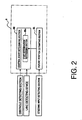
- FIG. 2 is a block diagram showing constituent features of a control unit of the vehicle driving control apparatus in accordance with the first embodiment
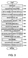
- FIG. 3 is a flowchart showing control steps executed by the control unit in accordance with the first embodiment
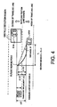
- Figure 4 is a conceptual diagram illustrating a relationship between a host vehicle employing the vehicle driving control apparatus and an obstacle (e.g., another vehicle);
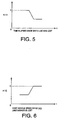
- Figure 5 is a graph illustrating an example characteristic of a lost gain Kt1 over time
- Figure 6 is a graph illustrating an example characteristic of a lost gain Kt2 with respect to the velocity of the host vehicle
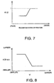
- Figure 7 is a graph illustrating an example characteristic of a lost gain Kt3 over time
- Figure 8 is a graph illustrating an example characteristic of a gain K2 with respect to the velocity of the host vehicle
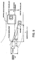
- Figure 9 is a conceptual diagram illustrating an example of a situation in which a lane marker cannot be detected and a curve exists ahead;
- Figure 10 is a conceptual diagram illustrating an example in which a lane marker cannot be detected and a headway point adjusted to be closer;
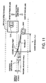
- Figure 11 is a conceptual diagram illustrating a relationship between an obstacle and a vehicle according to a second embodiment
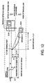
- Figure 12 is conceptual diagram illustrating a relationship between an obstacle and a vehicle according to a third embodiment
- Figure 13 is a graph illustrating a relationship between a recognition degree related gain and an ON time according to a fourth embodiment.
- Figure 14 is a graph illustrating a relationship between a recognition degree and a restoration time.
- a vehicle driving (lateral obstacle avoidance) control apparatus is illustrated in accordance with a first embodiment.
- This embodiment exemplifies a case in which the vehicle driving control apparatus is installed in a host vehicle with rear wheel drive. It would also be acceptable if the vehicle were a front wheel drive vehicle or a four wheel drive vehicle.
- the host vehicle has an automatic transmission and a differential gear.
- the host vehicle is also installed with a brake apparatus that can independently control the respective braking forces of the wheels, between front and rear wheels and between left and right wheels.
- the host vehicle is provided with a braking system including, among other things, a brake pedal 1, a booster 2, a master cylinder 3 and a reservoir 4.
- the brake pedal 1 is connected to the master cylinder 3 through the booster 2.
- the host vehicle also has wheels 5FL to 5RR that are provided with wheel cylinders 6FL to 6RR, respectively.
- the master cylinder 3 is connected to each of the wheel cylinders 6FL to 6RR of the wheels 5FL to 5RR through a hydraulic pressure circuit 30.
- the master cylinder 3 increases the brake fluid pressure in response to an amount by which the brake pedal 1 is depressed by the driver.
- the increased brake fluid pressure is transmitted through the hydraulic pressure circuit 30 and supplied to the wheel cylinders 6FL to 6RR of the wheels 5FL to 5RR.
- a brake fluid pressure control section 7 controls actuators in the hydraulic pressure circuit 30 so as to control the brake fluid pressure of each of the wheel cylinders 6FL to 6RR of the wheels 5FL to 5RR separately.
- the brake fluid pressure supplied to each of the wheel cylinders 6FL to 6RR of the wheels 5FL to 5RR is controlled to a value corresponding to a command value from a braking/driving force control unit 8.
- the actuators are, for example, proportional solenoids arranged such that they can control a reduction pressure of each of the wheel cylinders to any desired brake fluid pressure.
- a brake fluid pressure control section 7used in an anti-skid control system (ABS), a traction control system (TCS), or a vehicle dynamic control system (VDC) can be used to realize the brake fluid pressure control section 7 and the hydraulic pressure circuit 30.
- the brake fluid pressure control section 7 can also be configured to control the brake fluid pressure of each of the wheel cylinders 6FL to 6RR separately and independently. In such a case, when a brake fluid pressure command value is issued from the braking/driving force control unit 8 (described later), the brake fluid pressure of each of the wheel cylinders 6FL to 6RR of the wheels 5FL to 5RR is controlled according to the brake fluid pressure command value.
- a drive torque control unit 12 is provided in the vehicle.
- the drive torque control unit 12 controls a drive torque imparted to the drive wheels, i.e., the rear wheels 5RL and 5RR.
- the drive torque control is accomplished by controlling an operating state of an engine 9, a selected gear ratio of the automatic transmission 10, and an opening degree of a throttle valve 11.
- the drive torque control unit 12 controls a fuel injection quantity and an ignition timing while simultaneously controlling a throttle opening degree. In this way, the operating state of the engine 9 is controlled.
- the drive torque control unit 12 sends a drive torque value Tw to the braking/driving force control unit 8 (vehicle control device) as control information.
- the drive torque control unit 12 can also control the drive torques of the rear wheels 5RL and 5RR independently. However, when a drive torque command value is received from the braking/driving force control unit 8, the drive torque control unit 12 controls the torques of the drive wheels 5RL and 5RR in accordance with the drive torque command value.
- An imaging section 13 having an image processing function is provided on a front portion of the host vehicle.
- the imaging section 13 is used to detect a position of the host vehicle within a lane in which it is traveling.
- the imaging section 13 is a monocular camera, e.g., a CCD (charged coupled device) camera.
- the imaging section 13 photographs or records images of a region in front of the host vehicle.
- the imaging section 13 then applies an image processing to the photographed image in order to detect a lane marker (e.g., a white line dividing the lanes), and thus detect the lane in which the vehicle is traveling based on the detected lane marker.
- a lane marker e.g., a white line dividing the lanes
- the imaging section 13 calculates a yaw angle ⁇ front between a longitudinal axis of the host vehicle and the lane marker of the traveling lane, a transverse displacement amount Xfront with respect to the traveling lane and a curvature amount ⁇ of the traveling lane. The imaging section 13 then sends the calculated yaw angle ⁇ front, the transverse displacement amount Xfront and the lane curvature amount ⁇ to the braking/driving force control unit 8.
- the imaging section 13 sends a signal indicating that a lane marker could not be detected to the braking/driving force control unit 8.
- the imaging section 13 also sends information indicating a detection recognition degree to the braking/driving control unit 8 in accordance with an accuracy of a captured image. Even if the image quality (recognition degree) of a captured image is equal to or above a prescribed level, there are times when a lane marker cannot be detected, such as when the vehicle is near a toll booth where there are no lane markers.
- the imaging section 13 detects the lane marker and calculates the yaw angle ⁇ front based on the detected lane maker.
- the yaw angle ⁇ front is greatly affected by the accuracy with which the imaging section 13 detects the lane marker.
- the host vehicle is provided with a pair of radar devices 24L and 24R.
- the radar devices 24L and 24R serve as sensors for detecting obstacles traveling (located) on the left and right sides, respectively, of the vehicle.
- Each of the radar devices 24L and 24R is set such that it can detect if an obstacle exists within the region located laterally of the vehicle, this region including at least a prescribed blind spot area.
- a relative transverse position POSXobst, a relative longitudinal position DISTobst, and a relative longitudinal velocity dDISTobst of the vehicle can be detected with respect to an obstacle on the left or right side of the host vehicle.
- the host vehicle is provided with a master cylinder pressure sensor 17, an accelerator position sensor 18, a steering angle sensor 19, a turn signal switch 20, and wheel speed sensors 22FL to 22RR.
- the master cylinder pressure sensor 17 serves to detect an output pressure of the master cylinder 3, i.e., a master cylinder fluid pressure Pm.
- the accelerator position sensor 18 serves to detect a depression amount of an accelerator pedal, i.e., an accelerator position ⁇ t.
- the steering angle sensor 19 serves to detect a steering angle of the steering wheel 21.
- the turn signal switch 20 serves to detect a turning direction indicating operation of a turn signal device.
- Each of these sensors 22FL to 22RR sends a signal indicating a detected value to the braking/driving force control unit 8.
- the braking/driving force control unit 8 includes a future position estimating section 8A and an avoidance control start determining section 8B.
- the control avoidance control start determining section 8B includes a start determination suppressing section 8Ba.
- the braking/driving force control unit 8 is operatively coupled to the braking system. With this embodiment of the braking/driving force control unit 8, when the lane marker cannot be detected or a recognition degree thereof is low, impartation of a yaw moment by the aforementioned lateral obstacle avoidance control is suppressed. As a result, a necessary lateral obstacle avoidance control can be executed while preventing unnecessary starting and ending of the lateral obstacle avoidance control and preventing a driver from experiencing a feeling that something is odd about the host vehicle.
- the braking/driving force control unit 8 preferably includes a microcomputer with a braking/driving force control program that controls the braking system as discussed above.
- the braking/driving force control unit 8 can also include other conventional components such as an input interface circuit, an output interface circuit, and storage devices such as a ROM (Read Only Memory) device and a RAM (Random Access Memory) device.
- the microcomputer of the braking/driving force control unit 8 is programmed to control the braking system.
- the memory circuit stores processing results and control programs that are run by the processor circuit.
- the internal RAM of the braking/driving force control unit 8 stores statuses of operational flags and various control data.
- the internal ROM of the braking/driving force control unit 8 stores the programs for controlling various operations relating to the control of the braking/driving force. It will be apparent to those skilled in the art from this disclosure that the precise structure and algorithms for the braking/driving force control unit 8 can be any combination of hardware and software that will carry out the functions of the vehicle driving control apparatus.
- the future position estimating section 8A estimates a future position where the host vehicle MM will be after a prescribed amount of time, i.e., a future viewing time Tt, which is set in advance.
- the future viewing time Tt is used as a reference point in time for the host vehicle at which the avoidance control start determining section 8B will determine whether or not to start avoidance control.
- a first prescribed time Tt0 is set as a default value of the future viewing time Tt and used as a reference.
- the control avoidance control start determining section 8B is configured to determine that a lateral obstacle avoidance control should be started upon determining that an obstacle is detected laterally of the vehicle and a future position (future transverse position) of the vehicle estimated by the future position estimating section 8A is at a transverse position (prescribed lane-width direction position) corresponding to an obstacle distance X2obst determined using a lane marker located on a side closer to the obstacle as a reference or at a transverse position that is farther in a direction of the obstacle than the obstacle distance X2obst.
- the expression "farther in a direction of the obstacle than a transverse position corresponding to the obstacle distance X2obst” means that the future transverse position of the vehicle is located farther toward the outside of the lane from a middle of the lane than a transverse position corresponding to the obstacle distance X2obst.
- the braking/driving force control unit 8 calculates a yaw moment Ms to be used to control the vehicle such that the vehicle is prevented from approaching the obstacle (i.e., such that a yaw moment oriented toward the middle of the lane is generated).
- control avoidance control start determining section 8B determines that a lane marker cannot be detected or that a recognition degree is low, then the start determination suppressing section 8Ba sets the future viewing time Tt to a value shorter than a value used when a lane marker is detected, i.e., shorter than the future viewing time Tt0 set in advance as a default value. In other words, shortening the future viewing time Tt causes the control to intervene less readily, i.e., suppresses the likelihood that a need to start the control will be determined.
- the processing executed by braking/driving force control unit 8 will now be explained with reference to Figure 3 .
- the braking/driving force control unit 8 executes the processing with a timer interrupt each time a prescribed sampling time (control cycle time) ⁇ T (e.g., 10 msec) elapses.
- ⁇ T control cycle time
- the processing shown in Figure 3 does not include communication processing, information acquired from computational processing steps is consecutively updated in a storage device and necessary information is read from the storage device as needed.
- step S10 the braking/driving force control unit 8 reads various data from the aforementioned sensors, controllers, and control units. More specifically, it acquires wheel speeds Vwi (including four wheel speeds corresponding to the front and rear wheels, Vwrl, Vwrr, Vwfl, Vwfr), a steering angle ⁇ , and a master cylinder fluid pressure Pm detected by the sensors, as well as a turn signal switch signal.
- wheel speeds Vwi including four wheel speeds corresponding to the front and rear wheels, Vwrl, Vwrr, Vwfl, Vwfr
- ⁇ a steering angle ⁇
- Pm master cylinder fluid pressure
- step S20 the braking/driving force control unit 8 calculates a vehicle speed V.
- the vehicle speed V is calculated using one of the equations (1) shown below, depending on which wheels are the drive wheels.
- V Vwrl + Vwrr / 2 for front wheel drive ;
- V Vwfl + Vwfr / 2 for rear wheel drive
- Vwfl is the wheel speed of the left front wheel and Vwfr is the wheel speed of the right front wheel.
- Vwrl is the wheel speed of the left rear wheel and Vwrr is the wheel speed of the right rear wheel.
- the equations (1) calculate the vehicle speed V as the average value of the wheel speeds of the non-drive wheels.
- the vehicle speed V is calculated based on the wheel speeds of the front wheels (i.e., the latter equation) because the vehicle is a rear wheel drive vehicle.
- a separate automatic braking control system e.g., an ABS (anti-lock brake system)
- an estimated vehicle body speed estimated by the separate braking control system is acquired and used as the vehicle speed V.
- step S30 the braking/driving force control unit 8 determines the existence Lobst (i.e., existence or nonexistence) of an obstacle SM in a region laterally leftward of the host vehicle MM and the existence Robst (i.e., existence or nonexistence) of an obstacle SM in a region laterally rightward of the host vehicle MM. If more accurate sensors are used, then a relative position and relative velocity of obstacle(s) SM with respect to the host vehicle MM can be obtained. As shown in Figure 4 , a lateral region of the host vehicle MM in which an obstacle is detected includes positions diagonally rearward of the host vehicle MM.
- step S35 the braking/driving force control unit 8 determines a condition regarding detection of a line marker. In other words, based on the recognition information from the imaging section 13, the braking/driving force control unit 8 determines if left and right lane markers are detected and sets a lane marker flag CAMLOSTright and CAMLOSTleft.
- the lane marker flags CAMLOSTright and CAMLOSTleft serve as information regarding a right-side lane marker and a left-side lane marker, respectively.
- the lane marker flags CAMLOSTright and CAMLOSTleft are set to "0" when the corresponding lane marker is detected normally and set to "1" when the corresponding lane marker cannot be detected. Meanwhile, the flags are set to "2" when the recognition degree is lower than normal. The recognition degree is deemed to be lower than normal when the lane marker can be detected but the detection accuracy is low.
- step S40 from the imaging section 13, the braking/driving force control unit 8 reads a current transverse displacement (transverse position) Xfront of the host vehicle MM with respect to the lane in which the vehicle is traveling (traveling lane) and a curvature ⁇ front of the lane in which it is traveling from the imaging section 13.
- the curvature ⁇ front of the traveling lane does not necessarily have to be acquired from the imaging section 13. For example, it is acceptable to acquire curvature information recorded in a navigation system corresponding to the current position of the vehicle.
- the braking/driving force control unit 8 calculates a yaw angle ⁇ front of the host vehicle MM with respect to the lane in which it is traveling.
- the yaw angle ⁇ front is used to detect a traveling state within the lane. In this embodiment, a value measured by the imaging section 13 is used as the yaw angle ⁇ front.
- the yaw angle ⁇ front is calculated based on the lane marker that was detected immediately prior.
- the yaw angle ⁇ front can be calculated based on a lane marker in an area photographed by the imaging section 13.
- the yaw angle ⁇ front can be calculated, for example, using the equation (2) shown below based on a transverse displacement Xfront of the host vehicle MM. It is also acceptable to calculate the yaw angle ⁇ front in the same manner even when the lane marker is detected.
- the calculation of the yaw angle ⁇ front is not limited to using the lateral displacement Xfront as shown in the equation (2) above. For example, it is acceptable to extend the detected lane marker to a far point and calculate the yaw angle ⁇ front based on the extended lane marker. When a lane marker cannot be detected, the yaw angle ⁇ front should be detected using this processing.
- step S50 the braking/driving force control unit 8 calculates a neutral yaw rate ⁇ 'path.
- the neutral yaw rate ⁇ 'path is a yaw rate necessary for the host vehicle MM to maintain its travel along the lane in which it is traveling.
- the neutral yaw rate ⁇ 'path is zero when the vehicle is traveling along a straight path, but the neutral yaw rate ⁇ 'path changes depending on the curvature ⁇ front when the road is curved. Therefore, the curvature ⁇ front of the lane in which the vehicle is traveling is used when calculating the neutral yaw rate ⁇ 'path.
- the neutral yaw rate ⁇ 'path is set to "0" because the neutral yaw rate ⁇ 'path cannot be estimated accurately when the lane marker is not detected. Setting the neutral yaw rate ⁇ 'path to "0" is equivalent to assuming the vehicle is traveling along a straight path.
- step S60 the braking/driving force control unit 8 sets a future viewing time Tt.
- a preset future viewing time Tt0 is set as the value of the future viewing time Tt.
- the future viewing time Tt is an amount of time used to determine a threshold value for estimating a future proximity situation between the host vehicle MM having the braking/driving force control unit 8 and an obstacle SM.
- the future viewing time Tt indicates a point in time at which the avoidance control start determination section 8B will determine whether or not to start avoidance control.
- the future viewing time Tt0 is set to, for example, 1 second.
- the braking/driving force control unit 8 also calculates a target yaw rate ⁇ driver and a target yaw rate ⁇ driverhosei.
- the target yaw rate ⁇ driver is a target yaw rate generated in response to the steering.
- Kv is indicative of a gain value, as explained further below.
- the target yaw rate ⁇ driver is a target yaw rate generated in response to the steering.
- Kv is indicative of a gain value, as explained further below.
- the target yaw rate ⁇ driverhosei is calculated with the equation (4) shown below.
- the target yaw rate ⁇ driverhosei is a value obtained by subtracting the yaw rate ⁇ ' path necessary to travel in the traveling lane from the target yaw rate ⁇ driver. In this way, the effect of any steering performed in order to drive through a curve is eliminated.
- step S65 the braking/driving force control unit 8 adjusts the future viewing time Tt.
- the adjustment processing applied to the future viewing time Tt is selected according to the values of the lane marker flags CAMLOSTright and CAMLOSTleft.
- the lane marker flags CAMLOSTright and CAMLOSTleft indicate that the lane markers are being detected normally. If the lane marker flags CAMLOSTright and CAMLOSTleft indicate that the lane markers are being detected normally, then the braking/driving force control unit 8 proceeds directly to step S70, without adjusting the future viewing time Tt.
- the lane marker flags CAMLOSTright and CAMLOSTleft indicate that the lane markers are not being detected. If the lane marker flags CAMLOSTright and CAMLOSTleft indicate that the lane markers are not being detected, then the braking/driving force control unit 8 sets a first lost gain Kt1 based on a map like that shown in Figure 5 . As the lost time (time a lost state has continued since a lane marker became undetectable) becomes longer, the value to which the first lost gain Kt1 is set becomes smaller.
- the lost gain Kt1 is set to 1 (a first prescribed value) until the lost time reaches a first prescribed amount of time. After, the first prescribed amount of time has lapsed, the value of the lost gain Kt1 decreases as the lost time increases until the lost time reaches a second prescribed amount of time. After, the second prescribed amount of time has lapsed, the value of the lost gain Kt1 is set to a second prescribed value.
- the braking/driving force control unit 8 sets a second lost gain Kt2 based on a map like that shown in Figure 6 . If a vehicle speed V0 corresponding to when the lane marker became undetectable is equal to or smaller than a prescribed vehicle speed, then the second lost gain Kt2 is set such that when the vehicle speed is the smaller, the second lost gain Kt2 becomes smaller until the vehicle speed falls below a prescribed vehicle speed (e.g., Figure 6 ).
- a prescribed vehicle speed e.g., Figure 6
- the future viewing time Tt is then adjusted using the following equation: Tt ⁇ Tt ⁇ Kt1 ⁇ Kt2. Then, after adjusting the future viewing time Tt, the braking/driving force control unit 8 proceeds to step S70.
- a third lost gain Kt3 is set based on a recognition degree KD, as shown in Figure 7 . That is, as the recognition degree becomes lower, the value that is set as the third lost gain Kt3 becomes smaller.
- the future viewing time Tt is adjusted using the following equation: Tt ⁇ Tt ⁇ Kt3. Then, after adjusting the future viewing time Tt, the braking/driving force control unit 8 proceeds to step S70.
- the recognition degree KD is determined based on a boldness or sharpness (contrast with respect to the road surface) of an edge of a lane marker and a degree of tracking instability.
- the degree of tracking instability is a value obtained by using lane marker set based on a plurality of lane candidate points as a reference and applying a statistical computation to a difference between the reference lane marker and each of the lane candidate points.
- the statistical computation uses, for example, an average value of the differences, a standard deviation, or a total value. It is acceptable for a value obtained by setting, for example, a coefficient that becomes smaller as a difference between edge boldness values becomes smaller and a coefficient that becomes smaller as a tracking instability degree becomes larger and multiplying the set coefficients to obtain a recognition degree KD.
- recognition degrees KD It is also acceptable for each of a coefficient that becomes smaller as a difference between edge boldness values becomes smaller and a coefficient that becomes smaller as a tracking instability degree becomes larger to be set as recognition degrees KD. If a calculated recognition degree KD is equal to or smaller than a prescribed value set in advance, then the braking/driving force control unit 8 determines that the recognition degree is low.
- the future viewing time Tt is adjusted separately for left and right lane markers.
- the future viewing time Tt corresponding to the appropriate adjacent lane marker is selected for use depending on whether an obstacle is on the left or right side of the vehicle.
- step S70 the braking/driving force control unit 8 calculates an estimated future position ⁇ Xb of the vehicle in a transverse direction with respect to a current traveling lane position using the equation (5) below.
- the estimated future position ⁇ Xb of the vehicle is used to determine if the vehicle will depart from the current lane to change lanes.
- the estimated future position ⁇ Xb is used to determine whether or not to start a lateral obstacle avoidance control for avoiding the obstacle SM.
- the estimated future position ⁇ Xb is calculated separately for the left and right sides.
- ⁇ Xb K ⁇ 1 ⁇ ⁇ + K ⁇ 2 ⁇ ⁇ m + K ⁇ 3 ⁇ ⁇ m ⁇
- the value of the set gain K1 is a function of the vehicle speed
- the value of the set gain K2 is a function of the vehicle speed and the future viewing time
- the value of the set gain K3 is a function of the vehicle speed and the square of the future viewing time.
- ⁇ Xb max K ⁇ 2 ⁇ ⁇ m , K ⁇ 3 ⁇ ⁇ m ⁇
- step S80 the braking/driving force control unit 8 sets a control start determination threshold value to a prescribed lane-width direction position that is determined in advance. This determination threshold value is used to determine whether or not a lateral obstacle avoidance control will be started with respect to an obstacle SM located laterally of the host vehicle.
- a lane marker position is used as a reference and an obstacle distance X2obst indicating a lane-width direction position that is located laterally outward from the lane marker is set as the determination threshold value (see Figure 4 ).
- the obstacle distance X2obst is a value set as a distance with respect to an imaginary obstacle SM.
- the control processing is executed as though the obstacle SM exists at distance equal to the obstacle distance X2obst in an outward direction from the lane marker. It is acceptable to set the obstacle distance X2obst, i.e., the displacement from the lane marker to the imaginary obstacle SM, to 0. In such a case, the position of the lane marker and the position indicated by the obstacle distance X2obst are the same.
- a transverse distance X0 indicates a transverse distance between the host vehicle MM and the lane marker.
- the transverse distance ⁇ O - X0 between the lane marker and the obstacle is the obstacle distance X2obst.
- the transverse distance ⁇ O - X0 is the obstacle distance X2.
- an X-Y coordinate system in which a Y axis is oriented in along the direction in which the traveling lane extends and an X axis is oriented in a direction perpendicular to the direction of the road, i.e., in a widthwise direction of the lane.
- a transverse position of the obstacle SM is detected as a coordinate on the X axis.
- the relative transverse distance ⁇ O is found based on this transverse position.
- An obstacle detection region for detecting if an obstacle SM exists is set to span between prescribed longitudinal and transverse positions located laterally from the host vehicle MM.
- the longitudinal positions are set such that as the relative velocity at which the obstacle SM is approaching the host vehicle MM becomes larger, the obstacle detection region becomes larger.
- step S90 the braking/driving force control unit 8 executes a control start determination.
- the control unit 8 determines if there is an existence Lobst and/or Robst of an obstacle SM. If an obstacle exists on neither the left nor the right, the control unit sets a lateral obstacle avoidance control determination flag Fout_obst to OFF and proceeds to step S100.
- the braking/driving force control unit 8 determines to start control with respect to the obstacle SM because the host vehicle can be assumed to be changing lanes toward the obstacle SM. When it determines that control will be started with respect to the obstacle SM, the control unit 8 sets the lateral obstacle avoidance control determination flag Fout_obst to ON. If the aforementioned condition is not satisfied, i.e., if the estimated future position ⁇ Xb is smaller than the determination threshold value, then the braking/driving force control unit 8 sets the lateral obstacle avoidance control determination flag Fout_obst to OFF.
- an estimated future position ⁇ Xb is calculated separately for each of the left and right sides as ⁇ XbL and ⁇ XbR and separate determinations are executed for the left and right sides.
- the obstacle SM targeted by this control is not limited to vehicles located laterally rearward of the host vehicle MM; it can also be applied to oncoming vehicles traveling in an adjacent lane.
- the control unit 8 determines that a driver has performed a lane change or other driving operation that will cause the host vehicle MM to contact an obstacle SM when the following equation is satisfied, i.e., when an estimated future position ⁇ Xb of the host vehicle MM has reached the distance ⁇ O with respect to the detected obstacle SM, i.e., ⁇ Xb - X0 ⁇ ⁇ O - X0.
- the equation ⁇ Xb ⁇ ⁇ O is used because the meaning is the same.
- a dead zone can be established in which the lateral obstacle avoidance control is not performed. That is, a dead zone can be provided between a control intervention threshold value and a control end threshold value.
- the flag Fout_obst can only be set to ON when the flag Fout_obst is OFF. It is also acceptable to add a time-related condition for allowing the flag Fout_obst to be turned ON, such as requiring a prescribed amount of time to have elapsed since the flag Fout_obst was last set to OFF.
- the control can also be contrived such that when a prescribed amount of time Tcontrol has elapsed since the flag Fout_obst was determined to be ON, the flag Fout_obst is turned OFF and the control ends.
- a control execution direction Dout_obst is determined based on a determined direction of an estimated future position of the host vehicle.
- ABS anti-skid control system
- TCS traction control system
- VDC vehicle dynamic control system
- the lateral obstacle avoidance control determination flag Fout_obst is set to OFF. The flag Fout_obst is turned OFF when an automatic braking control is operating so that the lateral obstacle avoidance control will not be executed.
- This determination method accomplishes the same task as would be accomplished by setting a separate threshold value for each of the steering velocity ⁇ ', the steering angle ⁇ and the yaw angle ⁇ in a direction oriented toward the obstacle SM and setting the threshold values such that the closer the host vehicle MM is to the obstacle SM, the more difficult it is to determine that it is time for a lateral obstacle avoidance control to start.
- the reason the same task is accomplished is that the target yaw rate ⁇ m' is found based on a publicly known and widely used relationship between a steering angle and a vehicle speed.
- step S100 the braking/driving force control unit 8 executes a control processing so as to issue a warning.
- the braking/driving force control unit 8 issues a warning when it has determined in step S90 that a control start position (determination threshold value) has been reached. It is acceptable to perform the lateral obstacle avoidance control such that the warning is issued before a headway point, which is based on the aforementioned future viewing time Tt reaches a control start position.
- a prescribed gain Kbuzz Kbuzz > 1 might be used to obtain a longer future viewing time Tt than the future viewing time Tt used in step S90 to detect an avoidance control start.
- a warning can be issued when the headway point is determined in step S90 to have reached the control start position. It is also acceptable to configure the control such that when it is determined in step S90 that the obstacle avoidance system will be started, the avoidance control starts after a prescribed amount of time has elapsed.
- the gain K1recv is a proportional gain (yaw inertial moment) determined based on the vehicle specifications.
- the gain K2recv is a gain that varies according to the vehicle speed V.
- An example illustrating the gain K2recv is shown in Figure 8 .
- the gain K2recv has a large value in a low speed region and decreases inversely proportionally with respect to the vehicle speed after the vehicle speed reaches a certain value. After the vehicle speed V reaches another certain value, the gain K2recv remains fixed at a small value.
- the value of the set gain K1mom is a function of the vehicle speed
- the value of the set gain K2mom is a function of the vehicle speed and the future viewing time Tt.
- the gain K3 decreases as the future viewing time Tt increases.
- Ms K ⁇ 1 ⁇ recv ⁇ ⁇ Xb / L ⁇ Tt 2
- the equation (7) reflects a control time T indicating how long the yaw angle will be controlled.
- the control time T and the future viewing time Tt are equal, the time T required to return the vehicle is shorter when the future viewing time Tt is shorter.
- a control effect (amount) is stronger. Consequently, even if the future viewing time Tt is shortened, the control quantity obtained when the control is started will be larger because the gain K3 will be larger.
- the control can be executed in accordance with the situation without regard to the set future viewing time Tt such that the driver experiences less of a feeling that something is odd about the vehicle.
- the determination of the value of the flag Fout_obst serves to estimate a future change of the path of the vehicle based on steering information.
- step S120 the braking/driving force control unit 8 calculates a command for generating a target yaw moment Ms for avoiding the obstacle. After sending the calculated command, the control unit 8 returns to the start of the control sequence.
- a yaw rate Ms calculated according to this embodiment for avoiding an obstacle is generated by using braking and driving forces to produce a yaw moment.
- the pressure Pmf is a brake fluid pressure for the front wheels.
- the pressure Pmr is a brake fluid pressure for the rear wheels and is a value calculated based on the brake fluid pressure Pmf for the front wheels in accordance with a distribution between front and rear. For example, if a driver is operating a brake, then the brake fluid pressures Pmf and Pmr are set to values corresponding to a brake operation amount (master cylinder fluid pressure Pm).
- a front wheel target brake fluid pressure difference ⁇ Psf and a rear wheel target brake fluid pressure difference ⁇ Psr are calculated. More specifically, the target brake fluid pressure differences ⁇ Psf and ⁇ Psr are calculated according to the equations (10) and (11) shown below.
- ⁇ Psf 2 ⁇ Kbf ⁇ Ms ⁇ FRratio / Tr
- ⁇ Psf 2 ⁇ Kbr ⁇ Ms ⁇ 1 - FRratio / Tr
- the value of the tread Tr is assumed to be the same for both the front and the rear for convenience.
- Kbf and Kbr are determined based on brake specifications.
- the distribution of the braking forces generated at the wheels is determined according to the magnitude of the target yaw moment Ms.
- a prescribed value is given to each of the target brake fluid pressure differences ⁇ Psf and ⁇ Psr such that a braking force difference occurs between the left and right front wheels and between the left and right rear wheels, respectively.
- control execution direction Dout is set to RIGHT, i.e., if the vehicle exhibits a trend of departing from the lane with respect to a right-hand lane marker
- a braking/driving force difference is generated between left and right wheels such that the wheel braking forces are larger on the side where a lane departure is to be prevented.
- the estimated future position ⁇ Xb serves as a future transverse position where the vehicle will be after a future viewing time Tt has elapsed and is calculated based on a yaw angle ⁇ , a yaw angle velocity ⁇ m, and other parameters indicating a traveling state of the vehicle. If the estimated future position ⁇ Xb is on the same side as a detected obstacle SM and equals or exceeds an obstacle distance X2obst measured outward from lane marker used as a reference, then a lateral obstacle avoidance control for avoiding the obstacle SM is started (see Figure 4 ).
- a target yaw moment Ms is calculated as a control quantity based on the estimated future position ⁇ Xb and a braking/driving force control is executed such that the target yaw moment Ms is generated.
- a control is executed so as to generate a yaw moment oriented toward a middle of the lane in which the vehicle is traveling.
- the future viewing time Tt is adjusted in a direction of becoming shorter than a preset future viewing time Tt0. Also, as a state in which a lane marker cannot be detected (i.e., a state in which the value of the lane marker flag CAMLOSTright or CAMLOSTleft is 1) continues to become longer, the more readily the apparatus can determine that a degree of certainty regarding the traveling path is low. Therefore, the future viewing time Tt is shortened in accordance with the amount of time a state in which a lane marker cannot be detected has continued.
- this embodiment is configured to adjust the future viewing time Tt to a shorter time, as shown in Figure 10 .
- the headway point is moved closer to the current host vehicle position and it becomes more difficult for the lateral obstacle avoidance control to start. In this way, even though the lane marker cannot be detected, the unnecessary starts and stoppages of the control can be prevented.
- changes in the vehicle behavior resulting from the lateral obstacle avoidance control can be suppressed and the degree to which a driver experiences a feeling that something is odd about the vehicle can be reduced.
- lateral obstacle avoidance control is still executed with respect to lateral obstacles when necessary.
- the lateral obstacle avoidance control can be started when the driver deliberately steers toward an obstacle SM.
- the radar devices 24L and 24R constitute the obstacle detecting device.
- the imaging section 13 constitutes the lane detecting device.
- the steering angle sensor 19 constitutes the steering input detecting device.
- Step S70 constitutes the future position estimating section 8A.
- Steps S35 and S65 constitute the start determination suppressing section 8Ba.
- Steps S80 and S90 constitute the control start determination section 8B.
- the lane detecting device is configured to acquire information regarding an area surrounding the host vehicle employing the lateral obstacle avoidance control and detect a lane marker of a lane in which the vehicle is traveling.
- the future position estimating section or device is configured to estimate a future transverse position where the host vehicle will be after a prescribed amount of time has elapsed.
- the control start determining section is configured to determine that a control should be started when it determines that a future transverse position of the host vehicle estimated by the future position estimating device is positioned at a prescribed lane-width direction position that is determined using the lane marker as a reference or farther toward an outside of the lane from a middle of the lane than the prescribed lane-width direction position.
- the vehicle control unit is configured to control the vehicle such that a yaw moment oriented toward a middle of the lane in which the vehicle is traveling is imparted to the vehicle when the control start determining section determines that the control should be started.
- the vehicle control start determining section has a start determination suppressing section configured to suppress the occurrence of a determination that the control should be started when a recognition degree of the lane marker used by the control start determining section as a reference is low, i.e., to make a determination that the control should be started occur less readily when the recognition degree is low than when the recognition degree is normal.
- a starting of a lateral obstacle avoidance control is suppressed when the recognition degree of a lane marker of a lane in which the vehicle is traveling is low.
- a necessary lateral obstacle avoidance control can be executed while preventing unnecessary starting and ending of the control.
- the lateral obstacle avoidance control can be started when the driver deliberately steers toward an obstacle. As a result, even if the recognition degree of the lane marker is low, an appropriate lateral obstacle avoidance control can be executed.
- the control avoidance control start determining section 8B is configured to determine if the lateral obstacle avoidance control should be started based on a relationship between a future position of the vehicle and a determination threshold value (lane-width direction position) determined using a lane marker located on a side of the vehicle that is closer to an obstacle as a reference.
- the start determination suppressing section 8Ba is configured to suppress a start of the lateral obstacle avoidance control when the lane detecting device determines that a recognition degree of a lane marker on a side of the host vehicle that is closer to an obstacle has become low. In other words, it suppresses a determination that the control should be started when a recognition degree of the lane marker is low.
- a necessary lateral obstacle avoidance control can be executed with respect to an obstacle located laterally of the host vehicle but unnecessary starting and ending of the control can be prevented.
- the lateral obstacle avoidance control can be started when the driver deliberately steers toward an obstacle SM.
- a lateral obstacle avoidance control can be executed appropriately with respect to an obstacle located laterally of the host vehicle.
- the vehicle control device determines a future position of the vehicle with respect to an obstacle using the detected lane marker as a reference.
- the vehicle control device can determine if the degree to which the host vehicle is oriented toward an obstacle is appropriate even when the vehicle is being steered through a curve in the road. As a result, even if the host vehicle is traveling through a curve, a lateral obstacle avoidance control can be executed appropriately to avoid an obstacle.
- the start determination suppressing section 8Ba is configured to suppress a determination that the control should be started by shortening the prescribed amount of time used to estimate a future position of the vehicle. As a result, a control start determination can be suppressed easily.
- the control start determining section is configured to determine if the lateral obstacle avoidance control should be started based on the estimated lane marker when the lane detecting device cannot detect a lane marker.
- the start determination suppressing section is configured to suppress the occurrence of a determination that the control should be started when an estimated lane marker is used as a reference by the control start determining section, i.e., to make a determination that the control should be started occur less readily when an estimated lane marker is used than when the recognition degree of the lane marker is normal.
- a determination that the control should be started is suppressed when a lane marker of a lane in which the vehicle is traveling cannot be detected.
- a necessary lateral obstacle avoidance control can be executed while preventing unnecessary starting and ending of the control.
- the lateral obstacle avoidance control can be started when the driver deliberately steers toward an obstacle. As a result, even if a lane marker has become undetectable, an appropriate lateral obstacle avoidance control can be executed.
- the start determination suppressing section 8Ba suppresses a determination that the lateral obstacle avoidance control should be started in comparison with when the same amount of time is short.
- the vehicle control device is contrived such that as a recognition state of a lane marker continues to decline, it becomes more difficult to determine that the lateral obstacle avoidance control should be started.
- interventions of the lateral obstacle avoidance control in a manner causing a driver to experience a feeling that something is odd can be made to occur even less frequently.
- the start determination suppressing section 8Ba suppresses the control start more if the vehicle speed is low than if the vehicle speed is high. That is, the lower the vehicle speed is, the less readily a determination that the control should be started will occur.
- the vehicle control device is contrived such that when the start determination suppressing section is suppressing a determination by the control start determining section that the control should be started, the vehicle control device increases a control gain of a control quantity used to control the vehicle such that a yaw moment oriented toward a middle of the lane is imparted to the vehicle. That is, when a determination that the control should be started is prevented, a control gain of a control quantity is revised to a higher value.
- a large control quantity can be generated. More specifically, a larger control quantity can be generated when the vehicle has approached very close to an obstacle SM and a smaller control quantity can be generated when the vehicle has approached an obstacle SM but is farther away. As a result, a control quantity that is more in line with what a driver would feel to be appropriate can be generated.
- the future viewing time Tt is revised to a shorter amount of time by multiplying the future viewing time Tt by a lost gain that is determined based on a lost time, i.e., an amount of time that a state in which a lane marker cannot be detected has continued.
- a lost gain that is determined based on a lost time, i.e., an amount of time that a state in which a lane marker cannot be detected has continued.
- a headway point is adjusted and a determination that a control (obstacle avoidance control) should be started is suppressed.
- a control quantity (target yaw moment Ms) used during execution of the control is also adjusted.
- the estimated future position ⁇ Xb is a value related to a transverse position of the headway point.
- the position of the headway point is adjusted by multiplying the future viewing time Tt or the estimated future position ⁇ Xb by a gain Kt.
- the start timing of the lateral obstacle avoidance control is adjusted by multiplying the entire value indicating the headway point by the gain Kt.
- ⁇ Xb Kt ⁇ K ⁇ 1 ⁇ ⁇ + K ⁇ 2 ⁇ ⁇ m + K ⁇ 3 ⁇ ⁇ m ⁇
- Kt is the lost gain
- ⁇ Xb Kta ⁇ K ⁇ 1 ⁇ ⁇ + Ktb ⁇ K ⁇ 2 ⁇ ⁇ m + Ktc ⁇ K ⁇ 3 ⁇ ⁇ m ⁇
- the gains applied to each of ⁇ , ⁇ m, and ⁇ m' can be adjusted separately. For example, a determination that the control should be started can be suppressed by reducing the steering angle component more than the steering velocity component. That is, among the steering quantities resulting from steering input by the driver, a steering velocity component is adjusted by a larger amount relative to the steering angle component. In this way, the vehicle control device suppresses determinations that the lateral obstacle avoidance control should be started in response to corrective steering or normal intentional steering. Also, the control can be tailored such that executions of the lateral obstacle avoidance control that cause the driver to experience an odd feeling are reduced effectively when the lane marker cannot be easily seen but the lateral obstacle avoidance control can still be started when the driver deliberately steers toward an obstacle SM.
- a degree to which starting of the lateral obstacle avoidance control is suppressed is increased as an uncertainty regarding how much a shape of a path of the vehicle can change after the lane marker becomes undetectable increases.
- the steering angle and the steering velocity are used to determine if the vehicle is changing lanes toward the obstacle and could possibly contact the obstacle. Setting the gain to a smaller value in a situation where a corrective steering operation is likely to occur means that the values of the steering angle and the steering velocity have to be larger in order to determine that the lateral obstacle avoidance control should be started.
- the start determination suppressing section revises the steering angle component by a larger amount.
- a second embodiment of a vehicle driving control apparatus will now be explained with reference to the drawings. Parts that are the same as those of the first embodiment are indicated with the same reference numerals.
- the constituent features of this embodiment are basically the same as the constituent features of the first embodiment.
- the host vehicle equipped with this embodiment of the vehicle driving control apparatus has the same construction as seen in Figures 1 to 3 . However, the method of determining if the lateral obstacle avoidance control should be started is different.
- the first embodiment presents an example in which the vehicle control device executes a control start determination in step S90 when an obstacle SM exists on at least the left side or the right side of the vehicle.
- the vehicle control is contrived such that if a future transverse position of the host vehicle is located farther toward an outside in a widthwise direction of the traveling lane than a determination threshold value (a prescribed lane-width direction position with respect to a lane marker used as a reference), then the vehicle control device determines that the host vehicle could possibly depart from the lane and executes a control start determination in step S90 regardless of whether an obstacle SM exists.
- the vehicle control functions as a lane departure prevention control serving to prevent the host vehicle from departing from the lane.
- the obstacle distance X2obst - which is a position measured in a widthwise direction of a lane (lane-width direction position) with respect to a lane marker position that is used as a reference, is set to 0 or to a preset distance that is closer inward than the lane marker position.
- the obstacle distance X2obst is set to a negative value.
- the vehicle control is a lane departure prevention control contrived such that if a future transverse position of the host vehicle is located farther toward an outside in a widthwise direction of a lane than a determination threshold value, then the vehicle control device determines that the host vehicle could possibly depart from the lane and executes a control start determination regardless of whether an obstacle SM exists.
- the control is not configured to detect if an obstacle SM exists.
- the obstacle distance X2obst used in this embodiment is not an assumed distance between a lane marker and an obstacle as in the first embodiment. Instead, in this embodiment, it is merely a prescribed distance that is determined in advance and is only called an "obstacle distance X2obst" for convenience.
- Figure 11 is a conceptual diagram for this embodiment and corresponds to Figure 4 . Also in this embodiment, a value ⁇ O is not set because there is no need for a relative distance with respect to an obstacle.
- step S90 the vehicle control device executes a determination as to whether the control (lane departure prevention control) should be started if the condition defined by the equation below: ⁇ Xb ⁇ X0 + X2obst ( ⁇ X0)
- a lane departure prevention control prevents the host vehicle from departing from a lane, i.e., moving beyond a lane marker, is started when an estimated future position ⁇ Xb of the host vehicle is located at a prescribed lane-width direction position (obstacle distance X2obst) set in advance to be on an inward side of a lane marker or farther to an outside of the lane marker than the prescribed lane-width direction position (obstacle distance X2obst) set in advance (see Figure 11 ).
- a target yaw moment Ms is calculated as a control quantity based on the estimated future position ⁇ Xb and a braking/driving force control is executed such that the target yaw moment Ms is generated.
- the host vehicle MM is controlled in such a direction as to resist departing from the lane (deviating beyond the lane marker) by imparting to the vehicle a yaw moment oriented toward a middle of the lane. In this way, the host vehicle can be prevented from departing from the lane.
- this embodiment is the same as the first embodiment, including setting the future viewing time Tt according to a recognition degree of the lane marker.
- the control start is suppressed when a recognition degree of a lane marker of a lane in which the host vehicle is traveling is low. As a result, a necessary vehicle control can be executed while preventing unnecessary starting and ending of the lane departure prevention control. Thus, while starting of the lane departure prevention control that causes the driver to experience an odd feeling is reduced, the control can be started when the driver deliberately performs a steering operation. As a result, even if the recognition degree of the lane marker is low, an appropriate vehicle control for suppressing a lane departure can be executed.
- a third embodiment of a vehicle driving control apparatus will now be explained with reference to the drawings. Parts that are the same as those of the previously described embodiments are indicated with the same reference numerals.
- the constituent features of this embodiment are basically the same as the constituent features of the previously described embodiments.
- the host vehicle equipped with this embodiment of the vehicle driving control apparatus has the same construction as seen in Figures 1 to 3 . However, the method of suppressing a determination that the lateral obstacle avoidance control should be started is different.
- a future viewing time Tt is multiplied by a lost gain to revise the future viewing time Tt to a shorter value. In this way, a headway point is adjusted and a determination that a control should be started is suppressed.
- the estimated future position ⁇ Xb of the vehicle is multiplied by a lost gain in step S70 in order to suppress a determination that a control should be started.
- a determination that a control should be started is suppressed by adjusting an obstacle distance X2obst to a larger value.
- the obstacle distance X2obst is a prescribed lane-width direction position determined in advance with respect to a reference lane marker, the determination to start a control is suppressed by moving the prescribed lane-width direction position farther outside in a widthwise direction of the lane.
- the obstacle distance X2obst is a value serving to define the prescribed lane-width direction position determined in advance with respect to a reference lane marker.
- the obstacle distance X2obst is increased beyond default value by a revision coefficient ⁇ Oh (> 0).
- ⁇ Oh revision coefficient
- the vehicle control device determines whether to start a control in step S90, it determines that the control should be started if the condition expressed by the following equation is satisfied.
- X ⁇ 2 ⁇ Xb - XO ⁇ X ⁇ 2 ⁇ obst + ⁇ Oh or ⁇ Xb ⁇ ⁇ O + ⁇ Oh
- a prescribed lane-width direction position determined in advance with respect to a reference lane marker is moved farther outside in a widthwise direction of the lane.
- the start determination suppressing section suppresses a determination that a control should be started by moving a prescribed lane-width direction position determined in advance with respect to a reference lane marker farther outside in a widthwise direction of a lane. As a result, a control start determination can be suppressed easily.
- a fourth embodiment of a vehicle driving control apparatus will now be explained with reference to the drawings. Parts that are the same as those of the previously described embodiments are indicated with the same reference numerals.
- the constituent features of this embodiment are basically the same as the constituent features of the previously described embodiments.
- the host vehicle equipped with this embodiment of the vehicle driving control apparatus has the same construction as seen in Figures 1 to 3 .
- the method of determining if a recognition degree of a lane marker is low is different and a method of computing a current recognition degree KD of a lane marker when the recognition degree is low is different.
- the first embodiment presents an example in which an image processing is applied to an image photographed by the imaging section 13 and a recognition degree KD of a recognized lane marker is determined based on a recognition condition (e.g., edge boldness) of an image of the lane marker itself and a certainty (e.g., degree of tracking instability) of the lane marker itself.
- a recognition condition e.g., edge boldness
- a certainty e.g., degree of tracking instability
- the vehicle control device determines that a recognition degree of a lane marker is low when any of the following flags is ON: a transverse position invalid flag DFLGa, a curvature invalid flag DFLGb, a lane change flag DFLGc, a bridge detection flag DFLGd, a non-parallel lane marker determination flag DFLGe, and a transverse acceleration abnormality flag DFLGf. It is also acceptable to use only a portion of the aforementioned flags to determine if a recognition degree of a lane marker is low.
- the transverse position invalid flag DFLGa is turned ON when a difference between a current-cycle value of the transverse displacement Xfront of the host vehicle MM and a current position estimated based on a transverse displacement of a previous cycle or transverse displacement values of a plurality of recent cycles is larger than a prescribed difference.
- the prescribed difference is a value that can be assumed to be too large to be a change in the transverse displacement.
- the transverse displacement Xfront is computed based on a lane marker extracted from an image photographed by the imaging section 13.
- the curvature position invalid flag DFLGb is turned ON when a difference between a current-cycle value of the traveling lane curvature ⁇ front and a current curvature estimated based on a curvature value of a previous cycle or curvature values of a plurality of recent cycles is larger than a prescribed difference.
- the prescribed difference is a value that can be assumed to be too large to be a change in the lane curvature.
- the lane curvature ⁇ front is computed based on a lane marker extracted from an image photographed by the imaging section 13.
- the lane change flag DFLGc is turned ON when it is determined that the vehicle is changing lanes.
- the vehicle control device determines that the recognition degree of the lane marker is low when the vehicle is changing lanes.
- the bridge detection flag DFLGd is turned ON when a junction existing in front of the host vehicle vehicle is detected based on an image photographed by the imaging section 13 in a frontward traveling direction.
- "in front of the host vehicle vehicle” is defined to mean, for example, that the host vehicle MM will reach the junction after a prescribed amount of time (e.g., after 2 seconds).
- the vehicle control device determines that the recognition degree of the lane marker is low when a junction is detected in front of the host vehicle vehicle.
- Positions of a left and a right lane marker of a lane in which the vehicle is traveling imaging section 13 are extracted from an image photographed by the imaging section 13.
- the non-parallel lane marker flag DFLGe is turned ON when the relative positions of the extracted left and right lane markers are determined to be impossible in comparison with a normally expected relationship.
- impossible means that an interval (spacing) between the left and right lane markers is determined to be narrowing or that an interval (spacing) between the left and right lane markers is changing over time at a rate equal to or faster than a prescribed rate.
- the transverse acceleration abnormality flag DFLGf is turned ON when a difference between a current-cycle value of the yaw angle ⁇ front of the host vehicle MM with respect to a lane in which the vehicle is currently traveling and a current yaw angle estimated based on a yaw angle value from a previous cycle or plurality yaw angle values from recent cycles is larger than a prescribed difference.
- the prescribed difference is a value that can be assumed to be too large to be a change in yaw angle.
- the yaw angle ⁇ front is calculated by the imaging section 13.
- a recognition degree KD of a lane marker Upon determining that the recognition degree of the lane marker is low, a recognition degree KD of a lane marker will be computed.
- Gains Ka, Kab, Kc, Kd, Ke, and Kf are provided with respect to each of the transverse position invalid flag DFLGa, the curvature invalid flag DFLGb, the lane change flag DFLGc, the bridge detection flag DFLGd, the non-parallel lane marker determination flag DFLGe, and the transverse acceleration abnormality flag DFLGf, respectively.
- the gain Ka is set to 1 when the transverse position invalid flag DFLGa is OFF and changes in accordance with an amount of time the same flag has continuously been ON when the flag is ON. More specifically, the gain Ka decreases toward zero as the amount of time the flag has been ON increases.
- the gain Kb is set to 1 when the curvature invalid flag DFLGb is OFF and changes in accordance with an amount of time the same flag has continuously been ON when the flag is ON. More specifically, the gain Kb decreases toward zero as the amount of time the flag has been ON increases.
- the gain Kc is set to 1 when the lane change flag DFLGc is OFF and changes in accordance with an amount of time the same flag has continuously been ON when the flag is ON. More specifically, the gain Kc decreases toward zero as the amount of time the flag has been ON increases.
- the gain Kd is set to 1 when the bridge detection flag DFLGd is OFF and changes in accordance with an amount of time the same flag has continuously been ON when the flag is ON. More specifically, the gain Kd decreases toward zero as the amount of time the flag has been ON increases.
- the gain Ke is set to 1 when the non-parallel lane marker flag DFLGe is OFF and changes in accordance with an amount of time the same flag has continuously been ON when the flag is ON. More specifically, the gain Ke decreases toward zero as the amount of time the flag has been ON increases.
- the gain Kf is set to 1 when the transverse acceleration abnormality flag DFLGf is OFF and changes in accordance with an amount of time the same flag has continuously been ON when the flag is ON. More specifically, the gain Kf decreases toward zero as the amount of time the flag has been ON increases.
- KD Ka ⁇ Kb ⁇ Kc ⁇ Kd ⁇ Ke ⁇ Kf
- the recognition degree KD is set to 1 when all of the flags are OFF. Meanwhile, the larger the number of flags that are ON and/or the longer a flag or flags has continued to be ON, the closer to zero the value of the recognition degree KD is set.
- a recognition degree KD of a recognized lane marker can be determined based on something other than a recognition condition (e.g., edge boldness) of an image of the lane marker itself and a certainty (e.g., degree of tracking instability) of the lane marker itself.
- a recognition condition e.g., edge boldness
- a certainty e.g., degree of tracking instability
- a fifth embodiment of a vehicle driving control apparatus will now be explained with reference to the drawings. Parts that are the same as those of the previously described embodiments are indicated with the same reference numerals.
- the constituent features of this embodiment are basically the same as the constituent features of the previously described embodiments.
- the host vehicle equipped with this embodiment of the vehicle driving control apparatus has the same construction as seen in Figures 1 to 3 .
- this embodiment is different regarding a processing executed when a lane marker is detected normally again after having been undetectable or having been determined to be detectable with a low recognition degree.
- the future viewing time Tt is set to a future viewing time Tt0, which is a preset default value. Consequently, when a lane marker is detected normally again after having been undetectable or having been determined to be detectable with a low recognition degree, the future viewing time Tt is immediately set to the future viewing time Tt0.
- the first embodiment illustrates an example in which a control serving to suppress a determination that another control (e.g., obstacle avoidance control) should be started is aborted and normal control is restored when a lane marker is detected normally again.
- a control serving to suppress a determination that another control should be started is gradually lessened over a prescribed restoration time Tf.
- the control serving to suppress a determination that another control should be started is gradually lessened by gradually increasing the future viewing time Tt such that it returns to the default value after the restoration time Tf has elapsed.
- the restoration time Tf is set based on a recognition degree KD (degree which the lane marker can be recognized) as shown in Figure 14 . More specifically, the smaller a recognition degree KD occurring immediately before the lane marker became normally detectable again is, the larger restoration time Tf is set. If the lane marker could not be detected at all before becoming normally detectable, then the recognition degree KD occurring immediately before is assumed to be 0. Conversely, if the lane marker is already detected normally, then the recognition degree KD is set to 1.
- the future viewing time Tt is set in advance to a future viewing time Tt0 as a default value, and the process of setting the future viewing time Tt to the future viewing time Tt0 is omitted from step S60.
- step S65 the processing that will now be explained is added to the processing explained above about when the values of the lane marker flags CAMLOSTright and CAMLOSTleft are equal to zero (0) so as to be executed before the vehicle control device (control unit 8) proceeds to step S70.
- the values of the lane marker flags CAMLOSTright and CAMLOSTleft from the previous cycle (one control cycle prior) are checked and control processing is executed accordingly as will now be explained.
- the vehicle control device computers a restoration time Tf based on Figure 14 using the recognition degree KD. If the lane marker could not be detected at all, then the recognition degree KD is assumed to be 0.
- the vehicle control device also computes a time difference ⁇ Tt between the current future viewing time Tt and the default value Tt0.
- the vehicle control device then computes a number of control cycles corresponding to the restoration time Tf and multiplies the aforementioned time difference ⁇ Tt by the computed number of control cycles to obtain an amount of time ⁇ Ttx by which to increase the future viewing time per control cycle.
- the vehicle control device then increases the future viewing time Tt using the equation Tt ⁇ Tt + ⁇ Ttx and proceeds to step S70.
- the vehicle control device substitutes Tt0 as the value of the future viewing time Tt and proceeds to step S70. It is also acceptable to contrive the vehicle control device to set a counter to a value equal to the number of control cycles corresponding to the restoration time Tf and continue the processing until the counter reaches 0.
- the vehicle control device increases the future viewing time Tt using the equation Tt ⁇ Tt + ⁇ Ttx before proceeding to step S70.
- the start determination suppressing section is configured to gradually lessen suppression of a determination that a control should be started when it determines that a recognition degree at which the lane detecting device detects a lane marker has become normal, thereby restoring the ability to determine that the control should be started.
- This embodiment presents a method of restoring to a normal state when a determination that a control should be started is suppressed by adjusting a future viewing time Tt, as is done in the first embodiment.
- Such a restoration can be accomplished differently when, as in the second embodiment, a determination that a control should be started is suppressed by adjusting an obstacle distance X2obst (i.e., a lane-width direction position measured with respect to a reference lane marker) to a larger value, i.e., by moving the obstacle distance X2obst farther outside in a widthwise direction of a lane from a middle of the lane.
- an obstacle distance X2obst i.e., a lane-width direction position measured with respect to a reference lane marker
- the restoration can accomplished by gradually decreasing a revision coefficient ⁇ Oh to 0 over a period of time equal to a restoration time Tf set according to a recognition degree KD.
- a restoration can be accomplished in the same manner as in the embodiment except that the revision coefficient ⁇ Oh is adjusted instead of a future viewing time.
- a sixth embodiment of a vehicle driving control apparatus will now be explained with reference to the drawings. Parts that are the same as those of the previously described embodiments are indicated with the same reference numerals.
- the constituent features of this embodiment are basically the same as the constituent features of the previously described embodiments.
- the host vehicle equipped with this embodiment of the vehicle driving control apparatus has the same construction as seen in Figures 1 to 3 . However, the method of determining if the lateral obstacle avoidance control should be started is different.
- a determination of whether or not to start a control is executed in step S90 when an obstacle exists on at least one of the left and right sides of the host vehicle.
- a determination of whether or not to start a control is executed in step S90 regardless of whether an obstacle exists.
- step S90 the vehicle control device determines that the control should be started if an obstacle exists on at least one of the left and right sides of the host vehicle and the equation ⁇ Xb - XO ⁇ X2obst, or ⁇ Xb ⁇ ⁇ O is satisfied.
- the vehicle control device determines that the control should be started if the equation ⁇ Xb ⁇ X0 + X2obst ( ⁇ X0) is satisfied.
- the obstacle distance X2obst is set to a preset negative value.
- a future viewing time Tt1 that is smaller than the future viewing time Tt0 is used as the default value of the future viewing time Tt. In this way, when an obstacle exists on neither the left nor the right side of the vehicle, the threshold value for determining that the control should be started is closer to the vehicle and the future viewing time Tt1 used as a reference is shorter such that the control starts less readily.
- both a future viewing time Tt0 and a future viewing time Tt1 that is smaller than the future viewing time Tt0 are prepared in advance as default values of the future viewing time Tt.
- a first prescribed amount of time Tt0 and a second prescribed amount of time Tt1 that is shorter than the first prescribed amount of time Tt0 are provided for use as a prescribed amount of time. Furthermore, the first prescribed amount of time Tt0 is set as the prescribed amount of time when an obstacle detecting device detects an obstacle and the second prescribed amount of time Tt1 is set as the prescribed amount of time when the obstacle detecting device does not detect an obstacle.
- a driving support is executed which gives priority to preventing the host vehicle from approaching the obstacle. Meanwhile, when an obstacle is not detected, a driving support is executed to prevent the host vehicle from departing from the lane in which it is traveling.
- the prescribed amount of time used to determine if a control should be started is changed depending on the type of lateral obstacle avoidance control. As a result, an appropriate determination of when to start a lateral obstacle avoidance control can be made in accordance with the targeted type of lateral obstacle avoidance control.
- the following directional terms “forward”, “rearward”, “above”, “downward”, “vertical”, “horizontal”, “below” and “transverse” as well as any other similar directional terms refer to those directions of a vehicle equipped with the present invention. Accordingly, these terms, as utilized to describe the present invention should be interpreted relative to a vehicle equipped with the present invention.
- the term “detect” as used herein to describe an operation or function carried out by a component, a section, a device or the like includes a component, a section, a device or the like that does not require physical detection, but rather includes determining, measuring, modeling, predicting or computing or the like to carry out the operation or function.
- the term “configured” as used herein to describe a component, section or part of a device includes hardware and/or software that is constructed and/or programmed to carry out the desired function.
Landscapes
- Engineering & Computer Science (AREA)
- Transportation (AREA)
- Mechanical Engineering (AREA)
- Automation & Control Theory (AREA)
- Control Of Driving Devices And Active Controlling Of Vehicle (AREA)
- Regulating Braking Force (AREA)
- Control Of Position, Course, Altitude, Or Attitude Of Moving Bodies (AREA)
- Traffic Control Systems (AREA)
- Steering Control In Accordance With Driving Conditions (AREA)
- Control Of Vehicle Engines Or Engines For Specific Uses (AREA)
Claims (11)
- Fahrzeug-Fahrsteuerungseinrichtung, umfassend:eine Hinderniserfassungsvorrichtung (24) zum Erfassen eines seitlich des Host-Fahrzeugs vorhandenen Hindernisses,eine Lenkeingabe-Erfassungsvorrichtung (19) zum Erfassen einer von einem Fahrer ausgeführten Lenkeingabe,eine Fahrbahnerfassungsvorrichtung (13) zum Erfassen einer Fahrbahnmarkierung einer Fahrbahn, auf der das mit der Fahrzeugsteuerungseinrichtung ausgestattete Host-Fahrzeug fährt,eine Schätzvorrichtung einer künftigen Position zum Schätzen einer künftigen transversalen Position des Host-Fahrzeugs nach einer vorgegebenen Zeitspanne basierend auf der Lenkeingabe, die von der Lenkeingabe-Erfassungsvorrichtung erfasst wurde, undeine Fahrzeugsteuerungsvorrichtung (8) zum Ausführen einer Fahrzeugsteuerung hinsichtlich des Host-Fahrzeugs, sodass ein Giermoment, das zu einer Mitte der Fahrbahn gerichtet ist, auf der das Fahrzeug fährt, an das Host-Fahrzeug weitergegeben wird, wobeidie Fahrzeugsteuerungsvorrichtung (8) ferner einen Steuerungsstart-Ermittlungsabschnitt (8B) mit einem Startermittlungs-Unterdrückungsabschnitt (8Ba) umfasst,der Steuerungsstart-Ermittlungsabschnitt (8B) ermittelt, dass die Fahrzeugsteuerung gestartet werden sollte, wenn:- die Hinderniserfassungsvorrichtung das Hindernis erfasst, und- der Steuerungsstart-Ermittlungsabschnitt ermittelt, dass die künftige transversale Position des Host-Fahrzeugs, die von der Schätzvorrichtung einer künftigen Position geschätzt wurde, in seitlicher Richtung weiter zum Hindernis als eine vorgegebene Fahrbahnposition der Breite nach positioniert ist, die vorab unter Verwendung der Fahrbahnmarkierung als Referenz ermittelt wurde und sich auf einer Seite des Fahrzeugs näher am Hindernis befindet,der Startermittlungs-Unterdrückungsabschnitt (8Ba) ferner eine Weitergabe des Giermoments durch die Fahrzeug-Steuerungsvorrichtung unterdrückt, wenn ein Erkennungsgrad, mit dem die Fahrbahnerfassungsvorrichtung die Fahrbahnmarkierung erfasst, niedriger als ein vorgegebener Wert ist, indem eine Ermittlung unterdrückt wird, dass die Fahrzeugsteuerung gestartet werden sollte.
- Fahrzeug-Fahrsteuerungseinrichtung nach Anspruch 1, wobei der Startermittlungs-Unterdrückungsabschnitt (8Ba) die Ermittlung unterdrückt, dass die Fahrzeugsteuerung gestartet werden sollte, indem die vorgeschriebene Zeitspanne verkürzt wird, die von der Schätzvorrichtung einer künftigen Position verwendet wird, um die künftige transversale Position des Host-Fahrzeugs zu schätzen.
- Fahrzeug-Fahrsteuerungseinrichtung nach Anspruch 1, wobei der Startermittlungs-Unterdrückungsabschnitt (8Ba) die Ermittlung unterdrückt, dass die Fahrzeugsteuerung gestartet werden sollte, indem die vorgeschriebene Fahrbahnposition der Breite nach in Bezug auf die Fahrbahnmarkierung weiter zur Außenseite der Fahrbahn verändert wird.
- Fahrzeug-Fahrsteuerungseinrichtung nach einem der Ansprüche 1 bis 3, wobei
die Fahrbahnerfassungsvorrichtung (13) eine Position der Fahrbahnmarkierung basierend auf Informationen schätzt, die erhalten wurden, als die Fahrbahnmarkierung zuvor erfasst wurde, wenn die Fahrbahnerfassungsvorrichtung die Fahrbahnmarkierung nicht erfassen kann, und
der Steuerungsstart-Ermittlungsabschnitt (8B) ermittelt, ob die Fahrzeugsteuerung basierend auf der Fahrbahnmarkierung gestartet werden sollte, die geschätzt wird, wenn die Fahrbahnerfassungsvorrichtung die Fahrbahnmarkierung nicht erfassen kann. - Fahrzeug-Fahrsteuerungseinrichtung nach Anspruch 4, wobei der Startermittlungs-Unterdrückungsabschnitt (8Ba) die Ermittlung unterdrückt, dass die Fahrzeugsteuerung gestartet werden sollte, sodass die Ermittlung, dass die Fahrzeugsteuerung gestartet werden sollte, später erfolgt, wenn sich eine Zeitspanne verlängert, in der die Fahrbahnmarkierung weiterhin nicht erfassbar ist.
- Fahrzeug-Fahrsteuerungseinrichtung nach Anspruch 1, wobei der Startermittlungs-Unterdrückungsabschnitt (8Ba) die Ermittlung unterdrückt, dass die Fahrzeugsteuerung gestartet werden sollte, sodass die Ermittlung, dass die Fahrzeugsteuerung gestartet werden sollte, später erfolgt, wenn sich eine Host-Fahrzeuggeschwindigkeit verringert, wenn der Erkennungsgrad für die Fahrbahnmarkierung niedriger als der vorgeschriebene Wert ist.
- Fahrzeug-Fahrsteuerungseinrichtung nach Anspruch 1, wobei die Schätzvorrichtung einer künftigen Position die künftige transversale Position des Host-Fahrzeugs nach der vorgegebenen Zeitspanne unter Verwendung einer Lenkgröße schätzt, die eine Lenkwinkelkomponente und eine Lenkgeschwindigkeitskomponente umfasst, und
der Startermittlungs-Unterdrückungsabschnitt die Ermittlung unterdrückt, dass die Fahrzeugsteuerung gestartet werden sollte, indem die Lenkwinkelkomponente in Bezug auf die Lenkgeschwindigkeitskomponente vergrößert wird. - Fahrzeug-Fahrsteuerungseinrichtung nach einem der Ansprüche 1 bis 7, wobei
die Fahrzeugsteuerungsvorrichtung (8) eine Steuerungsverstärkung einer zur Steuerung des Host-Fahrzeugs verwendeten Steuerungsgröße erhöht, sodass das Giermoment auf das Host-Fahrzeug weitergegeben wird, wenn der Startermittlungs-Unterdrückungsabschnitt die Ermittlung durch den Steuerungsstart-Ermittlungsabschnitt unterdrückt, dass die Fahrzeugsteuerung gestartet werden sollte. - Fahrzeug-Fahrsteuerungseinrichtung nach einem der Ansprüche 1 bis 8, wobei
der Startermittlungs-Unterdrückungsabschnitt (8Ba) eine Unterdrückungsgröße, die zur Unterdrückung der Ermittlung verwendet wird, dass die Fahrzeugsteuerung gestartet werden sollte, graduell nach einer Ermittlung wiederherstellt, dass der Erkennungsgrad, mit dem die Fahrbahnerfassungsvorrichtung die Fahrbahnmarkierung erfasst, gleichgroß oder größer als der vorgeschriebene Wert geworden ist, und
eine Wiederherstellungszeit zur Durchführung einer Wiederherstellung der Unterdrückungsgröße länger eingestellt wird, wenn sich der Erkennungsgrad verringert, mit dem die Fahrbahnerfassungsvorrichtung die Fahrbahnmarkierung erfasst, bevor der Erfassungsgrad gleichgroß oder größer als der vorgeschriebene Wert wird. - Fahrzeug-Fahrsteuerungseinrichtung nach einem der Ansprüche 1 bis 9, ferner umfassend:eine Hinderniserfassungsvorrichtung zur Erfassung eines seitlich des Fahrzeugs vorhandenen Hindernisses, wobeidie Schätzvorrichtung einer künftigen Position eine erste vorgegebene Zeitspanne als vorgegebene Zeitspanne festlegt, die zur Schätzung der künftigen transversalen Position des Host-Fahrzeugs verwendet wird, wenn die Hinderniserfassungsvorrichtung das Hindernis erfasst, unddie Schätzvorrichtung einer künftigen Position eine zweite vorgegebene Zeitspanne, die kürzer als die erste vorgegebene Zeitspanne ist, als vorgegebene Zeitspanne festlegt, die zur Schätzung der künftigen transversale Position des Host-Fahrzeugs verwendet wird, wenn die Hinderniserfassungsvorrichtung das Hindernis nicht erfasst.
- Fahrzeug-Fahrsteuerungsverfahren, das folgende Schritte umfasst:Erfassen eines Hindernisses seitlich eines Host-Fahrzeugs unter Verwendung des Fahrzeug-Fahrsteuerungsverfahrens,Erfassen einer Lenkeingabe, die von einem Fahrer ausgeführt wird,Schätzen einer künftigen transversalen Position des Host-Fahrzeugs nach einer vorgegebenen Zeitspanne basierend auf der von einem Fahrer ausgeführten Lenkeingabe,Steuern eines auf das Host-Fahrzeug weitergegebenen Giermoments, wobei das Giermoment zu einer Mitte einer Fahrbahn gerichtet ist, auf der das Host-Fahrzeug fährt, nachdem ermittelt wurde, dass die künftige transversale Position des Host-Fahrzeugs in seitlicher Richtung weiter zum Hindernis als eine vorgegebene Fahrbahnposition der Breite nach positioniert ist, die vorab unter Verwendung einer Fahrbahnmarkierung ermittelt wurde, die sich auf einer Seite des Fahrzeugs näher am Hindernis als eine Referenz befindet, undUnterdrücken einer Steuerung des auf das Host-Fahrzeug weitergegebenen Giermoments, wenn die Fahrbahnmarkierung auf der Seite der Fahrbahn näher am Hindernis nicht erfasst werden kann, oder wenn ein Erkennungsgrad der Fahrbahnmarkierung auf der Seite des Fahrzeugs näher am Hindernis niedriger als ein vorgegebener Wert ist.
Priority Applications (3)
| Application Number | Priority Date | Filing Date | Title |
|---|---|---|---|
| EP12004132.2A EP2495149B1 (de) | 2008-07-29 | 2009-07-01 | Fahrzeugantriebssteuerungsvorrichtung und Fahrzeugantriebssteuerungsverfahren |
| EP12004131.4A EP2495148B1 (de) | 2008-07-29 | 2009-07-01 | Fahrzeugantriebssteuerungsvorrichtung und Fahrzeugantriebssteuerungsverfahren |
| EP12004130.6A EP2495147B1 (de) | 2008-07-29 | 2009-07-01 | Fahrzeugantriebssteuerungsvorrichtung und Fahrzeugantriebssteuerungsverfahren |
Applications Claiming Priority (2)
| Application Number | Priority Date | Filing Date | Title |
|---|---|---|---|
| JP2008194862 | 2008-07-29 | ||
| JP2009106502A JP5359516B2 (ja) | 2008-07-29 | 2009-04-24 | 車両運転支援装置及び車両運転支援方法 |
Related Child Applications (3)
| Application Number | Title | Priority Date | Filing Date |
|---|---|---|---|
| EP12004131.4A Division EP2495148B1 (de) | 2008-07-29 | 2009-07-01 | Fahrzeugantriebssteuerungsvorrichtung und Fahrzeugantriebssteuerungsverfahren |
| EP12004130.6A Division EP2495147B1 (de) | 2008-07-29 | 2009-07-01 | Fahrzeugantriebssteuerungsvorrichtung und Fahrzeugantriebssteuerungsverfahren |
| EP12004132.2A Division EP2495149B1 (de) | 2008-07-29 | 2009-07-01 | Fahrzeugantriebssteuerungsvorrichtung und Fahrzeugantriebssteuerungsverfahren |
Publications (2)
| Publication Number | Publication Date |
|---|---|
| EP2149487A1 EP2149487A1 (de) | 2010-02-03 |
| EP2149487B1 true EP2149487B1 (de) | 2012-05-30 |
Family
ID=41057328
Family Applications (4)
| Application Number | Title | Priority Date | Filing Date |
|---|---|---|---|
| EP09008642A Active EP2149487B1 (de) | 2008-07-29 | 2009-07-01 | Fahrzeugantriebssteuerungsvorrichtung und Fahrzeugantriebssteuerungsverfahren |
| EP12004130.6A Active EP2495147B1 (de) | 2008-07-29 | 2009-07-01 | Fahrzeugantriebssteuerungsvorrichtung und Fahrzeugantriebssteuerungsverfahren |
| EP12004131.4A Active EP2495148B1 (de) | 2008-07-29 | 2009-07-01 | Fahrzeugantriebssteuerungsvorrichtung und Fahrzeugantriebssteuerungsverfahren |
| EP12004132.2A Active EP2495149B1 (de) | 2008-07-29 | 2009-07-01 | Fahrzeugantriebssteuerungsvorrichtung und Fahrzeugantriebssteuerungsverfahren |
Family Applications After (3)
| Application Number | Title | Priority Date | Filing Date |
|---|---|---|---|
| EP12004130.6A Active EP2495147B1 (de) | 2008-07-29 | 2009-07-01 | Fahrzeugantriebssteuerungsvorrichtung und Fahrzeugantriebssteuerungsverfahren |
| EP12004131.4A Active EP2495148B1 (de) | 2008-07-29 | 2009-07-01 | Fahrzeugantriebssteuerungsvorrichtung und Fahrzeugantriebssteuerungsverfahren |
| EP12004132.2A Active EP2495149B1 (de) | 2008-07-29 | 2009-07-01 | Fahrzeugantriebssteuerungsvorrichtung und Fahrzeugantriebssteuerungsverfahren |
Country Status (3)
| Country | Link |
|---|---|
| US (1) | US8655549B2 (de) |
| EP (4) | EP2149487B1 (de) |
| JP (1) | JP5359516B2 (de) |
Families Citing this family (47)
| Publication number | Priority date | Publication date | Assignee | Title |
|---|---|---|---|---|
| JP5070171B2 (ja) * | 2008-09-19 | 2012-11-07 | 日立オートモティブシステムズ株式会社 | 車両制御装置 |
| JP4957752B2 (ja) | 2009-06-12 | 2012-06-20 | トヨタ自動車株式会社 | 進路評価装置 |
| JP5088350B2 (ja) * | 2009-06-16 | 2012-12-05 | 日産自動車株式会社 | 車両運転支援装置及び車両運転支援方法 |
| US8072351B1 (en) * | 2009-07-21 | 2011-12-06 | Absher Ii Charlie A | Blind spot alert apparatus |
| EP2302412B1 (de) * | 2009-09-29 | 2012-08-15 | Volvo Car Corporation | System und Verfahren zur Beurteilung einer Frontalzusammenstoßdrohung eines Automobils |
| EP2544941B1 (de) * | 2010-03-06 | 2014-09-10 | Continental Teves AG & Co. oHG | Spurhaltesystem für ein kraftfahrzeug |
| KR101340779B1 (ko) * | 2010-03-17 | 2013-12-11 | 주식회사 만도 | 기준 추종 위치 설정 방법 및 차선 유지 제어 시스템 |
| KR20110125282A (ko) * | 2010-05-13 | 2011-11-21 | 주식회사 만도 | 차선 유지 제어 방법 |
| JP2012079118A (ja) * | 2010-10-01 | 2012-04-19 | Toyota Motor Corp | 走行支援装置及び方法 |
| DE102011018159A1 (de) * | 2011-04-19 | 2012-10-25 | GM Global Technology Operations LLC (n. d. Gesetzen des Staates Delaware) | Vorrichtung und Verfahren zur Fahrerunterstützung |
| EP2752833B1 (de) * | 2011-08-31 | 2016-05-18 | Nissan Motor Company, Limited | Fahrzeug-fahrhilfe |
| JP5852471B2 (ja) * | 2012-02-28 | 2016-02-03 | 株式会社豊田中央研究所 | 車両制御装置、操舵模擬装置、及びプログラム |
| CN104736417B (zh) * | 2012-10-04 | 2017-03-01 | 日产自动车株式会社 | 转轮控制装置 |
| JP5711721B2 (ja) * | 2012-12-03 | 2015-05-07 | 富士重工業株式会社 | 車両の運転支援制御装置 |
| US11190738B2 (en) | 2012-12-28 | 2021-11-30 | Robert Bosch Gmbh | Vehicle standstill recognition |
| JP5783204B2 (ja) * | 2013-05-01 | 2015-09-24 | トヨタ自動車株式会社 | 運転支援装置および運転支援方法 |
| US8996197B2 (en) * | 2013-06-20 | 2015-03-31 | Ford Global Technologies, Llc | Lane monitoring with electronic horizon |
| JP5917472B2 (ja) | 2013-11-08 | 2016-05-18 | 本田技研工業株式会社 | 運転支援装置 |
| JP6260233B2 (ja) * | 2013-12-02 | 2018-01-17 | 富士通株式会社 | 情報処理装置、カメラ取付角度の推定方法、及びプログラム |
| JP6081349B2 (ja) * | 2013-12-24 | 2017-02-15 | 本田技研工業株式会社 | 車両の旋回制御システム |
| JP6210012B2 (ja) * | 2014-03-28 | 2017-10-11 | マツダ株式会社 | 車線維持制御装置 |
| JP6126043B2 (ja) * | 2014-04-25 | 2017-05-10 | 本田技研工業株式会社 | 路外逸脱抑制支援装置および路外逸脱抑制支援方法 |
| JP6404922B2 (ja) * | 2014-06-19 | 2018-10-17 | 日立オートモティブシステムズ株式会社 | 物体認識装置及びそれを用いた車両走行制御装置 |
| JP6285321B2 (ja) * | 2014-08-25 | 2018-02-28 | 株式会社Soken | 道路形状認識装置 |
| DE102014219689A1 (de) * | 2014-09-29 | 2016-03-31 | Robert Bosch Gmbh | Verfahren und Steuergerät zur Fahrspurüberwachung eines Fahrzeugs |
| JP6300182B2 (ja) * | 2015-09-15 | 2018-03-28 | マツダ株式会社 | 車線維持制御装置 |
| JP6323473B2 (ja) * | 2016-02-25 | 2018-05-16 | トヨタ自動車株式会社 | 走行制御装置 |
| GB2551767B (en) * | 2016-06-30 | 2021-07-07 | Arrival Ltd | Electro-hydraulic power steering system |
| JP6774259B2 (ja) * | 2016-08-10 | 2020-10-21 | 株式会社Subaru | 車両の走行制御装置 |
| CN106896811B (zh) * | 2016-12-22 | 2018-11-09 | 北京京东尚科信息技术有限公司 | 可移动装置的控制方法及系统 |
| JP6583252B2 (ja) * | 2016-12-27 | 2019-10-02 | トヨタ自動車株式会社 | 運転支援装置 |
| JP2018116369A (ja) * | 2017-01-16 | 2018-07-26 | 株式会社Soken | 車線認識装置 |
| CN110191833B (zh) * | 2017-01-23 | 2022-02-22 | 本田技研工业株式会社 | 车辆控制系统、车辆控制方法及存储介质 |
| US9988048B1 (en) * | 2017-03-03 | 2018-06-05 | GM Global Technology Operations LLC | Lane detection systems and methods |
| US20200103907A1 (en) * | 2017-03-30 | 2020-04-02 | Honda Motor Co., Ltd. | Vehicle control system, vehicle control method, and vehicle control program |
| JP6543828B2 (ja) * | 2017-06-01 | 2019-07-17 | 本田技研工業株式会社 | 車両制御システム、車両制御方法、および車両制御プログラム |
| JP6617886B2 (ja) | 2017-07-06 | 2019-12-11 | トヨタ自動車株式会社 | 車両走行支援装置 |
| KR102553247B1 (ko) * | 2018-04-27 | 2023-07-07 | 주식회사 에이치엘클레무브 | 전방 차량 추종 제어 시 안전성을 향상할 수 있는 차선 유지 보조 시스템 및 방법 |
| KR102463723B1 (ko) * | 2018-11-07 | 2022-11-07 | 현대자동차주식회사 | 군집주행 차량의 조향 제어 장치 및 그 방법 |
| CN110356394B (zh) * | 2019-07-31 | 2020-09-08 | 重庆长安汽车股份有限公司 | 一种车辆主动避让障碍物的方法、装置及汽车 |
| JP7121714B2 (ja) * | 2019-09-17 | 2022-08-18 | 本田技研工業株式会社 | 車両制御システム |
| US11718296B2 (en) | 2019-12-09 | 2023-08-08 | Bendix Commercial Vehicle Systems Llc | Using shared traffic information to support adaptive cruise control (ACC) between platooning vehicles |
| JP7197554B2 (ja) * | 2020-12-28 | 2022-12-27 | 本田技研工業株式会社 | 車両制御システム及び区画線推定方法 |
| JP7472866B2 (ja) | 2021-07-06 | 2024-04-23 | トヨタ自動車株式会社 | 車両用操舵ガイドトルク制御装置 |
| JP2023107675A (ja) * | 2022-01-24 | 2023-08-03 | 株式会社Subaru | 車両の運転支援装置、及び、車両の運転支援システム |
| CN115019523B (zh) * | 2022-05-31 | 2023-10-17 | 南京邮电大学 | 基于最小化压力差的深度强化学习交通信号协调优化控制方法 |
| CN118082868B (zh) * | 2024-04-17 | 2024-06-21 | 四川轻化工大学 | 一种基于区块链的自动驾驶汽车控制方法及系统 |
Family Cites Families (55)
| Publication number | Priority date | Publication date | Assignee | Title |
|---|---|---|---|---|
| DE7023427U (de) | 1970-06-23 | 1970-09-17 | Bremshey & Co | Schirmstockendteil |
| JP3183966B2 (ja) * | 1992-04-20 | 2001-07-09 | マツダ株式会社 | 車両の走行制御装置 |
| JP3169483B2 (ja) * | 1993-06-25 | 2001-05-28 | 富士通株式会社 | 道路環境認識装置 |
| JPH08253160A (ja) | 1995-03-15 | 1996-10-01 | Koyo Seiko Co Ltd | 車両の操舵装置 |
| JPH1031799A (ja) * | 1996-07-15 | 1998-02-03 | Toyota Motor Corp | 自動走行制御装置 |
| US6185492B1 (en) * | 1997-07-09 | 2001-02-06 | Toyota Jidosha Kabushiki Kaisha | Vehicle steering control apparatus for assisting a steering effort to move a vehicle along a line desired by a driver |
| US6282478B1 (en) * | 1997-07-10 | 2001-08-28 | Aisin Seiki Kabushiki Kaisha | Travelling direction correction apparatus |
| JP3358709B2 (ja) * | 1997-08-11 | 2002-12-24 | 富士重工業株式会社 | 車両用運転支援装置 |
| JP3393584B2 (ja) * | 1997-09-18 | 2003-04-07 | 三菱自動車工業株式会社 | 車線逸脱防止装置 |
| JP3763211B2 (ja) * | 1998-07-10 | 2006-04-05 | 日産自動車株式会社 | レーンキープシステム |
| JP3704987B2 (ja) * | 1999-01-27 | 2005-10-12 | 三菱自動車工業株式会社 | 車両走行制御装置 |
| JP2002002427A (ja) * | 2000-06-15 | 2002-01-09 | Mazda Motor Corp | 車両用制御装置 |
| JP3630100B2 (ja) * | 2000-12-27 | 2005-03-16 | 日産自動車株式会社 | 車線検出装置 |
| JP3738709B2 (ja) * | 2001-07-13 | 2006-01-25 | 日産自動車株式会社 | 車線逸脱警報装置 |
| JP2003040132A (ja) * | 2001-07-27 | 2003-02-13 | Mitsubishi Motors Corp | 走行レーン逸脱防止装置 |
| JP3585874B2 (ja) * | 2001-09-04 | 2004-11-04 | 本田技研工業株式会社 | 車両の走行制御装置 |
| JP3760827B2 (ja) * | 2001-09-28 | 2006-03-29 | 日産自動車株式会社 | 車線逸脱防止装置 |
| JP4327389B2 (ja) * | 2001-10-17 | 2009-09-09 | 株式会社日立製作所 | 走行レーン認識装置 |
| JP3642310B2 (ja) * | 2001-11-20 | 2005-04-27 | 日産自動車株式会社 | 車線逸脱防止装置 |
| DE10218010A1 (de) * | 2002-04-23 | 2003-11-06 | Bosch Gmbh Robert | Verfahren und Vorrichtung zur Querführungsunterstützung bei Kraftfahrzeugen |
| DE10251357A1 (de) * | 2002-11-05 | 2004-05-13 | Daimlerchrysler Ag | Setzen oder Abschalten eines Fahrtrichtungsanzeigers |
| JP4005483B2 (ja) * | 2002-11-20 | 2007-11-07 | 日産自動車株式会社 | 車線逸脱防止装置 |
| JP3823924B2 (ja) * | 2003-01-31 | 2006-09-20 | 日産自動車株式会社 | 車両挙動制御装置 |
| JP3870911B2 (ja) * | 2003-02-10 | 2007-01-24 | 日産自動車株式会社 | 車線逸脱防止装置 |
| JP2004243904A (ja) * | 2003-02-14 | 2004-09-02 | Nissan Motor Co Ltd | 車線逸脱防止装置 |
| JP3922194B2 (ja) | 2003-03-11 | 2007-05-30 | 日産自動車株式会社 | 車線逸脱警報装置 |
| JP3873919B2 (ja) * | 2003-03-20 | 2007-01-31 | 日産自動車株式会社 | 車線逸脱防止装置 |
| JP3900099B2 (ja) * | 2003-03-20 | 2007-04-04 | 日産自動車株式会社 | 車線逸脱防止装置 |
| JP3906821B2 (ja) * | 2003-04-23 | 2007-04-18 | 日産自動車株式会社 | 車線逸脱防止装置 |
| JP2004322787A (ja) * | 2003-04-23 | 2004-11-18 | Nissan Motor Co Ltd | 車線逸脱防止装置 |
| JP3979339B2 (ja) * | 2003-05-12 | 2007-09-19 | 日産自動車株式会社 | 車線逸脱防止装置 |
| JP4013825B2 (ja) * | 2003-05-22 | 2007-11-28 | 日産自動車株式会社 | 車両用走行制御装置 |
| JP3982483B2 (ja) * | 2003-11-13 | 2007-09-26 | 日産自動車株式会社 | 車線逸脱防止装置 |
| JP3979382B2 (ja) * | 2003-12-03 | 2007-09-19 | 日産自動車株式会社 | 車線逸脱防止装置 |
| JP4389567B2 (ja) * | 2003-12-03 | 2009-12-24 | 日産自動車株式会社 | 車線逸脱防止装置 |
| JP2005182407A (ja) * | 2003-12-18 | 2005-07-07 | Nissan Motor Co Ltd | 車線逸脱防止装置 |
| US7482916B2 (en) * | 2004-03-15 | 2009-01-27 | Anita Au | Automatic signaling systems for vehicles |
| DE102005018697A1 (de) * | 2004-06-02 | 2005-12-29 | Daimlerchrysler Ag | Verfahren und Vorrichtung zur Warnung eines Fahrers im Falle eines Verlassens der Fahrspur |
| JP4291741B2 (ja) * | 2004-06-02 | 2009-07-08 | トヨタ自動車株式会社 | 車線逸脱警報装置 |
| KR20060049706A (ko) * | 2004-07-20 | 2006-05-19 | 아이신세이끼가부시끼가이샤 | 차량의 레인주행지원장치 |
| JP4229051B2 (ja) * | 2004-11-26 | 2009-02-25 | 日産自動車株式会社 | 運転意図推定装置、車両用運転操作補助装置および車両用運転操作補助装置を備えた車両 |
| JP2006182129A (ja) * | 2004-12-27 | 2006-07-13 | Nissan Motor Co Ltd | 車線逸脱防止装置 |
| JP4867313B2 (ja) | 2004-12-27 | 2012-02-01 | 日産自動車株式会社 | 車線逸脱防止装置 |
| JP4124213B2 (ja) * | 2005-05-27 | 2008-07-23 | トヨタ自動車株式会社 | 車両逸脱防止装置 |
| JP4802592B2 (ja) * | 2005-07-29 | 2011-10-26 | 日産自動車株式会社 | 車線逸脱防止装置 |
| DE102005036265A1 (de) | 2005-08-02 | 2007-02-08 | Epcos Ag | Funkenstrecke |
| JP4169022B2 (ja) * | 2005-08-05 | 2008-10-22 | 日産自動車株式会社 | 車両用運転操作補助装置および車両用運転操作補助装置を備える車両 |
| JP4735147B2 (ja) * | 2005-09-14 | 2011-07-27 | 日産自動車株式会社 | 車線逸脱防止装置 |
| JP4638370B2 (ja) * | 2006-03-29 | 2011-02-23 | 富士重工業株式会社 | 車線逸脱防止装置 |
| ATE519647T1 (de) * | 2006-06-11 | 2011-08-15 | Volvo Technology Corp | Verfahren und vorrichtung zur verwendung eines automatisierten spurhaltesystems zur bewahrung von seitlichem fahrzeugabstand |
| DE102006027325A1 (de) * | 2006-06-13 | 2007-12-20 | Robert Bosch Gmbh | Spurhalteassistent mit Spurwechselfunktion |
| JP2008044546A (ja) * | 2006-08-18 | 2008-02-28 | Nissan Motor Co Ltd | 車線逸脱防止装置 |
| JP5177076B2 (ja) * | 2008-07-28 | 2013-04-03 | 日産自動車株式会社 | 車両運転支援装置及び車両運転支援方法 |
| JP5088350B2 (ja) * | 2009-06-16 | 2012-12-05 | 日産自動車株式会社 | 車両運転支援装置及び車両運転支援方法 |
| JP5375752B2 (ja) * | 2009-07-15 | 2013-12-25 | 日産自動車株式会社 | 車両運転支援装置 |
-
2009
- 2009-04-24 JP JP2009106502A patent/JP5359516B2/ja active Active
- 2009-07-01 EP EP09008642A patent/EP2149487B1/de active Active
- 2009-07-01 EP EP12004130.6A patent/EP2495147B1/de active Active
- 2009-07-01 EP EP12004131.4A patent/EP2495148B1/de active Active
- 2009-07-01 EP EP12004132.2A patent/EP2495149B1/de active Active
- 2009-07-06 US US12/497,787 patent/US8655549B2/en active Active
Also Published As
| Publication number | Publication date |
|---|---|
| US8655549B2 (en) | 2014-02-18 |
| US20100030430A1 (en) | 2010-02-04 |
| EP2495149B1 (de) | 2014-01-22 |
| EP2149487A1 (de) | 2010-02-03 |
| EP2495147A2 (de) | 2012-09-05 |
| EP2495147A3 (de) | 2013-05-01 |
| EP2495148A3 (de) | 2013-05-01 |
| EP2495149A3 (de) | 2013-05-01 |
| JP5359516B2 (ja) | 2013-12-04 |
| EP2495148A2 (de) | 2012-09-05 |
| JP2010052716A (ja) | 2010-03-11 |
| EP2495148B1 (de) | 2014-01-22 |
| EP2495149A2 (de) | 2012-09-05 |
| EP2495147B1 (de) | 2014-01-22 |
Similar Documents
| Publication | Publication Date | Title |
|---|---|---|
| EP2149487B1 (de) | Fahrzeugantriebssteuerungsvorrichtung und Fahrzeugantriebssteuerungsverfahren | |
| EP2149486B1 (de) | Fahrzeugantriebssteuerungsvorrichtung und Fahrzeugantriebssteuerungsverfahren | |
| CN102470866B (zh) | 车辆驾驶辅助装置及车辆驾驶辅助方法 | |
| JP5407952B2 (ja) | 車両運転支援装置及び車両運転支援方法 | |
| EP1880912B1 (de) | System zur Spurhaltung | |
| JP5088350B2 (ja) | 車両運転支援装置及び車両運転支援方法 | |
| EP2062796B1 (de) | Spurabweichungsverhinderungsvorrichtung und -verfahren | |
| JP5375752B2 (ja) | 車両運転支援装置 | |
| EP1674361B1 (de) | System zur Spurhaltung | |
| JP5256907B2 (ja) | 車線逸脱防止装置及びその方法 | |
| JP5359092B2 (ja) | 車両運転支援装置及び車両運転支援方法 | |
| JP5309764B2 (ja) | 側方障害物回避装置及び側方障害物回避方法 | |
| JP4517854B2 (ja) | 車線逸脱防止装置及び車線逸脱防止方法 | |
| JP5387204B2 (ja) | 車両運転支援装置及び車両運転支援方法 | |
| JP2007030696A (ja) | 運転者車線変更意思判定方法及び車線逸脱防止装置 | |
| JP3979393B2 (ja) | 車線逸脱防止装置 | |
| JP4862313B2 (ja) | 車両の走行制御装置 |
Legal Events
| Date | Code | Title | Description |
|---|---|---|---|
| PUAI | Public reference made under article 153(3) epc to a published international application that has entered the european phase |
Free format text: ORIGINAL CODE: 0009012 |
|
| 17P | Request for examination filed |
Effective date: 20090701 |
|
| AK | Designated contracting states |
Kind code of ref document: A1 Designated state(s): AT BE BG CH CY CZ DE DK EE ES FI FR GB GR HR HU IE IS IT LI LT LU LV MC MK MT NL NO PL PT RO SE SI SK SM TR |
|
| AX | Request for extension of the european patent |
Extension state: AL BA RS |
|
| 17Q | First examination report despatched |
Effective date: 20100715 |
|
| GRAP | Despatch of communication of intention to grant a patent |
Free format text: ORIGINAL CODE: EPIDOSNIGR1 |
|
| RIC1 | Information provided on ipc code assigned before grant |
Ipc: G08G 1/16 20060101ALI20120103BHEP Ipc: B60T 8/1755 20060101ALI20120103BHEP Ipc: B60W 30/12 20060101AFI20120103BHEP Ipc: B60W 10/18 20120101ALI20120103BHEP |
|
| GRAS | Grant fee paid |
Free format text: ORIGINAL CODE: EPIDOSNIGR3 |
|
| GRAA | (expected) grant |
Free format text: ORIGINAL CODE: 0009210 |
|
| AK | Designated contracting states |
Kind code of ref document: B1 Designated state(s): AT BE BG CH CY CZ DE DK EE ES FI FR GB GR HR HU IE IS IT LI LT LU LV MC MK MT NL NO PL PT RO SE SI SK SM TR |
|
| REG | Reference to a national code |
Ref country code: GB Ref legal event code: FG4D |
|
| REG | Reference to a national code |
Ref country code: CH Ref legal event code: EP |
|
| REG | Reference to a national code |
Ref country code: AT Ref legal event code: REF Ref document number: 559928 Country of ref document: AT Kind code of ref document: T Effective date: 20120615 |
|
| REG | Reference to a national code |
Ref country code: IE Ref legal event code: FG4D |
|
| REG | Reference to a national code |
Ref country code: DE Ref legal event code: R096 Ref document number: 602009007257 Country of ref document: DE Effective date: 20120726 |
|
| REG | Reference to a national code |
Ref country code: NL Ref legal event code: VDEP Effective date: 20120530 |
|
| REG | Reference to a national code |
Ref country code: LT Ref legal event code: MG4D Effective date: 20120530 |
|
| PG25 | Lapsed in a contracting state [announced via postgrant information from national office to epo] |
Ref country code: FI Free format text: LAPSE BECAUSE OF FAILURE TO SUBMIT A TRANSLATION OF THE DESCRIPTION OR TO PAY THE FEE WITHIN THE PRESCRIBED TIME-LIMIT Effective date: 20120530 Ref country code: LT Free format text: LAPSE BECAUSE OF FAILURE TO SUBMIT A TRANSLATION OF THE DESCRIPTION OR TO PAY THE FEE WITHIN THE PRESCRIBED TIME-LIMIT Effective date: 20120530 Ref country code: SE Free format text: LAPSE BECAUSE OF FAILURE TO SUBMIT A TRANSLATION OF THE DESCRIPTION OR TO PAY THE FEE WITHIN THE PRESCRIBED TIME-LIMIT Effective date: 20120530 Ref country code: NO Free format text: LAPSE BECAUSE OF FAILURE TO SUBMIT A TRANSLATION OF THE DESCRIPTION OR TO PAY THE FEE WITHIN THE PRESCRIBED TIME-LIMIT Effective date: 20120830 Ref country code: CY Free format text: LAPSE BECAUSE OF FAILURE TO SUBMIT A TRANSLATION OF THE DESCRIPTION OR TO PAY THE FEE WITHIN THE PRESCRIBED TIME-LIMIT Effective date: 20120530 Ref country code: IS Free format text: LAPSE BECAUSE OF FAILURE TO SUBMIT A TRANSLATION OF THE DESCRIPTION OR TO PAY THE FEE WITHIN THE PRESCRIBED TIME-LIMIT Effective date: 20120930 |
|
| REG | Reference to a national code |
Ref country code: AT Ref legal event code: MK05 Ref document number: 559928 Country of ref document: AT Kind code of ref document: T Effective date: 20120530 |
|
| PG25 | Lapsed in a contracting state [announced via postgrant information from national office to epo] |
Ref country code: LV Free format text: LAPSE BECAUSE OF FAILURE TO SUBMIT A TRANSLATION OF THE DESCRIPTION OR TO PAY THE FEE WITHIN THE PRESCRIBED TIME-LIMIT Effective date: 20120530 Ref country code: HR Free format text: LAPSE BECAUSE OF FAILURE TO SUBMIT A TRANSLATION OF THE DESCRIPTION OR TO PAY THE FEE WITHIN THE PRESCRIBED TIME-LIMIT Effective date: 20120530 Ref country code: SI Free format text: LAPSE BECAUSE OF FAILURE TO SUBMIT A TRANSLATION OF THE DESCRIPTION OR TO PAY THE FEE WITHIN THE PRESCRIBED TIME-LIMIT Effective date: 20120530 Ref country code: GR Free format text: LAPSE BECAUSE OF FAILURE TO SUBMIT A TRANSLATION OF THE DESCRIPTION OR TO PAY THE FEE WITHIN THE PRESCRIBED TIME-LIMIT Effective date: 20120831 |
|
| PG25 | Lapsed in a contracting state [announced via postgrant information from national office to epo] |
Ref country code: BE Free format text: LAPSE BECAUSE OF FAILURE TO SUBMIT A TRANSLATION OF THE DESCRIPTION OR TO PAY THE FEE WITHIN THE PRESCRIBED TIME-LIMIT Effective date: 20120530 |
|
| PG25 | Lapsed in a contracting state [announced via postgrant information from national office to epo] |
Ref country code: RO Free format text: LAPSE BECAUSE OF FAILURE TO SUBMIT A TRANSLATION OF THE DESCRIPTION OR TO PAY THE FEE WITHIN THE PRESCRIBED TIME-LIMIT Effective date: 20120530 Ref country code: AT Free format text: LAPSE BECAUSE OF FAILURE TO SUBMIT A TRANSLATION OF THE DESCRIPTION OR TO PAY THE FEE WITHIN THE PRESCRIBED TIME-LIMIT Effective date: 20120530 Ref country code: SK Free format text: LAPSE BECAUSE OF FAILURE TO SUBMIT A TRANSLATION OF THE DESCRIPTION OR TO PAY THE FEE WITHIN THE PRESCRIBED TIME-LIMIT Effective date: 20120530 Ref country code: DK Free format text: LAPSE BECAUSE OF FAILURE TO SUBMIT A TRANSLATION OF THE DESCRIPTION OR TO PAY THE FEE WITHIN THE PRESCRIBED TIME-LIMIT Effective date: 20120530 Ref country code: CZ Free format text: LAPSE BECAUSE OF FAILURE TO SUBMIT A TRANSLATION OF THE DESCRIPTION OR TO PAY THE FEE WITHIN THE PRESCRIBED TIME-LIMIT Effective date: 20120530 Ref country code: NL Free format text: LAPSE BECAUSE OF FAILURE TO SUBMIT A TRANSLATION OF THE DESCRIPTION OR TO PAY THE FEE WITHIN THE PRESCRIBED TIME-LIMIT Effective date: 20120530 Ref country code: EE Free format text: LAPSE BECAUSE OF FAILURE TO SUBMIT A TRANSLATION OF THE DESCRIPTION OR TO PAY THE FEE WITHIN THE PRESCRIBED TIME-LIMIT Effective date: 20120530 |
|
| PG25 | Lapsed in a contracting state [announced via postgrant information from national office to epo] |
Ref country code: IT Free format text: LAPSE BECAUSE OF FAILURE TO SUBMIT A TRANSLATION OF THE DESCRIPTION OR TO PAY THE FEE WITHIN THE PRESCRIBED TIME-LIMIT Effective date: 20120530 Ref country code: MK Free format text: LAPSE BECAUSE OF FAILURE TO SUBMIT A TRANSLATION OF THE DESCRIPTION OR TO PAY THE FEE WITHIN THE PRESCRIBED TIME-LIMIT Effective date: 20120530 Ref country code: PT Free format text: LAPSE BECAUSE OF FAILURE TO SUBMIT A TRANSLATION OF THE DESCRIPTION OR TO PAY THE FEE WITHIN THE PRESCRIBED TIME-LIMIT Effective date: 20121001 Ref country code: PL Free format text: LAPSE BECAUSE OF FAILURE TO SUBMIT A TRANSLATION OF THE DESCRIPTION OR TO PAY THE FEE WITHIN THE PRESCRIBED TIME-LIMIT Effective date: 20120530 Ref country code: MC Free format text: LAPSE BECAUSE OF NON-PAYMENT OF DUE FEES Effective date: 20120731 |
|
| PLBE | No opposition filed within time limit |
Free format text: ORIGINAL CODE: 0009261 |
|
| STAA | Information on the status of an ep patent application or granted ep patent |
Free format text: STATUS: NO OPPOSITION FILED WITHIN TIME LIMIT |
|
| PG25 | Lapsed in a contracting state [announced via postgrant information from national office to epo] |
Ref country code: ES Free format text: LAPSE BECAUSE OF FAILURE TO SUBMIT A TRANSLATION OF THE DESCRIPTION OR TO PAY THE FEE WITHIN THE PRESCRIBED TIME-LIMIT Effective date: 20120910 |
|
| 26N | No opposition filed |
Effective date: 20130301 |
|
| REG | Reference to a national code |
Ref country code: IE Ref legal event code: MM4A |
|
| REG | Reference to a national code |
Ref country code: DE Ref legal event code: R097 Ref document number: 602009007257 Country of ref document: DE Effective date: 20130301 |
|
| PG25 | Lapsed in a contracting state [announced via postgrant information from national office to epo] |
Ref country code: BG Free format text: LAPSE BECAUSE OF FAILURE TO SUBMIT A TRANSLATION OF THE DESCRIPTION OR TO PAY THE FEE WITHIN THE PRESCRIBED TIME-LIMIT Effective date: 20120830 Ref country code: MT Free format text: LAPSE BECAUSE OF FAILURE TO SUBMIT A TRANSLATION OF THE DESCRIPTION OR TO PAY THE FEE WITHIN THE PRESCRIBED TIME-LIMIT Effective date: 20120530 Ref country code: IE Free format text: LAPSE BECAUSE OF NON-PAYMENT OF DUE FEES Effective date: 20120701 |
|
| REG | Reference to a national code |
Ref country code: CH Ref legal event code: PL |
|
| PG25 | Lapsed in a contracting state [announced via postgrant information from national office to epo] |
Ref country code: TR Free format text: LAPSE BECAUSE OF FAILURE TO SUBMIT A TRANSLATION OF THE DESCRIPTION OR TO PAY THE FEE WITHIN THE PRESCRIBED TIME-LIMIT Effective date: 20120530 Ref country code: LI Free format text: LAPSE BECAUSE OF NON-PAYMENT OF DUE FEES Effective date: 20130731 Ref country code: CH Free format text: LAPSE BECAUSE OF NON-PAYMENT OF DUE FEES Effective date: 20130731 |
|
| PG25 | Lapsed in a contracting state [announced via postgrant information from national office to epo] |
Ref country code: SM Free format text: LAPSE BECAUSE OF FAILURE TO SUBMIT A TRANSLATION OF THE DESCRIPTION OR TO PAY THE FEE WITHIN THE PRESCRIBED TIME-LIMIT Effective date: 20120530 Ref country code: LU Free format text: LAPSE BECAUSE OF NON-PAYMENT OF DUE FEES Effective date: 20120701 |
|
| PG25 | Lapsed in a contracting state [announced via postgrant information from national office to epo] |
Ref country code: HU Free format text: LAPSE BECAUSE OF FAILURE TO SUBMIT A TRANSLATION OF THE DESCRIPTION OR TO PAY THE FEE WITHIN THE PRESCRIBED TIME-LIMIT Effective date: 20090701 |
|
| REG | Reference to a national code |
Ref country code: FR Ref legal event code: PLFP Year of fee payment: 8 |
|
| REG | Reference to a national code |
Ref country code: FR Ref legal event code: PLFP Year of fee payment: 9 |
|
| REG | Reference to a national code |
Ref country code: FR Ref legal event code: PLFP Year of fee payment: 10 |
|
| REG | Reference to a national code |
Ref country code: DE Ref legal event code: R084 Ref document number: 602009007257 Country of ref document: DE |
|
| REG | Reference to a national code |
Ref country code: GB Ref legal event code: 746 Effective date: 20230922 |
|
| PGFP | Annual fee paid to national office [announced via postgrant information from national office to epo] |
Ref country code: GB Payment date: 20250619 Year of fee payment: 17 |
|
| PGFP | Annual fee paid to national office [announced via postgrant information from national office to epo] |
Ref country code: FR Payment date: 20250619 Year of fee payment: 17 |
|
| PGFP | Annual fee paid to national office [announced via postgrant information from national office to epo] |
Ref country code: DE Payment date: 20250620 Year of fee payment: 17 |