EP2097192B2 - Phosphorhaltige formstoffmischung zur herstellung von giessformen für die metallverarbeitung - Google Patents
Phosphorhaltige formstoffmischung zur herstellung von giessformen für die metallverarbeitung Download PDFInfo
- Publication number
- EP2097192B2 EP2097192B2 EP07819175.6A EP07819175A EP2097192B2 EP 2097192 B2 EP2097192 B2 EP 2097192B2 EP 07819175 A EP07819175 A EP 07819175A EP 2097192 B2 EP2097192 B2 EP 2097192B2
- Authority
- EP
- European Patent Office
- Prior art keywords
- mold
- material mixture
- casting
- molding material
- proportion
- Prior art date
- Legal status (The legal status is an assumption and is not a legal conclusion. Google has not performed a legal analysis and makes no representation as to the accuracy of the status listed.)
- Active
Links
Images


Classifications
-
- B—PERFORMING OPERATIONS; TRANSPORTING
- B22—CASTING; POWDER METALLURGY
- B22C—FOUNDRY MOULDING
- B22C1/00—Compositions of refractory mould or core materials; Grain structures thereof; Chemical or physical features in the formation or manufacture of moulds
- B22C1/16—Compositions of refractory mould or core materials; Grain structures thereof; Chemical or physical features in the formation or manufacture of moulds characterised by the use of binding agents; Mixtures of binding agents
- B22C1/18—Compositions of refractory mould or core materials; Grain structures thereof; Chemical or physical features in the formation or manufacture of moulds characterised by the use of binding agents; Mixtures of binding agents of inorganic agents
- B22C1/185—Compositions of refractory mould or core materials; Grain structures thereof; Chemical or physical features in the formation or manufacture of moulds characterised by the use of binding agents; Mixtures of binding agents of inorganic agents containing phosphates, phosphoric acids or its derivatives
-
- B—PERFORMING OPERATIONS; TRANSPORTING
- B22—CASTING; POWDER METALLURGY
- B22C—FOUNDRY MOULDING
- B22C1/00—Compositions of refractory mould or core materials; Grain structures thereof; Chemical or physical features in the formation or manufacture of moulds
- B22C1/16—Compositions of refractory mould or core materials; Grain structures thereof; Chemical or physical features in the formation or manufacture of moulds characterised by the use of binding agents; Mixtures of binding agents
- B22C1/18—Compositions of refractory mould or core materials; Grain structures thereof; Chemical or physical features in the formation or manufacture of moulds characterised by the use of binding agents; Mixtures of binding agents of inorganic agents
- B22C1/186—Compositions of refractory mould or core materials; Grain structures thereof; Chemical or physical features in the formation or manufacture of moulds characterised by the use of binding agents; Mixtures of binding agents of inorganic agents contaming ammonium or metal silicates, silica sols
- B22C1/188—Alkali metal silicates
-
- B—PERFORMING OPERATIONS; TRANSPORTING
- B22—CASTING; POWDER METALLURGY
- B22C—FOUNDRY MOULDING
- B22C1/00—Compositions of refractory mould or core materials; Grain structures thereof; Chemical or physical features in the formation or manufacture of moulds
- B22C1/16—Compositions of refractory mould or core materials; Grain structures thereof; Chemical or physical features in the formation or manufacture of moulds characterised by the use of binding agents; Mixtures of binding agents
- B22C1/20—Compositions of refractory mould or core materials; Grain structures thereof; Chemical or physical features in the formation or manufacture of moulds characterised by the use of binding agents; Mixtures of binding agents of organic agents
- B22C1/26—Compositions of refractory mould or core materials; Grain structures thereof; Chemical or physical features in the formation or manufacture of moulds characterised by the use of binding agents; Mixtures of binding agents of organic agents of carbohydrates; of distillation residues therefrom
Definitions
- the invention relates to the use of a casting mold for light metal casting obtained by a method and using a mold material mixture according to claim 1.
- Casting molds for the production of metal bodies are essentially produced in two versions.
- the so-called cores or forms form a first group. From these, the casting mold is assembled, which essentially represents the negative mold of the casting to be produced.
- a second group consists of hollow bodies, so-called feeders, which act as equalizing reservoirs. These absorb liquid metal, with appropriate measures being taken to ensure that the metal remains in the liquid phase longer than the metal that is in the casting mold that forms the negative mold. If the metal solidifies in the negative mold, liquid metal can flow out of the compensating reservoir to compensate for the volume contraction that occurs when the metal solidifies.
- Casting molds consist of a refractory material, for example quartz sand, the grains of which are bonded by a suitable binder after the casting mold has been formed, in order to ensure sufficient mechanical strength of the casting mold.
- a refractory base material that has been treated with a suitable binder is therefore used for the production of casting moulds.
- the refractory basic molding material is preferably in a free-flowing form, so that it can be filled into a suitable hollow mold and compacted there.
- the binder creates a solid bond between the particles of the basic molding material, so that the casting mold has the required mechanical stability.
- Casting molds have to meet various requirements. During the casting process itself, they first have to have sufficient stability and temperature resistance to accommodate the liquid metal in the hollow mold formed from one or more (partial) casting molds. After the start of the solidification process, the mechanical stability of the casting mold is ensured by a solidified metal layer that forms along the walls of the cavity. The material of the casting mold must now decompose under the influence of the heat emitted by the metal in such a way that it loses its mechanical strength, i.e. the cohesion between individual particles of the refractory material is broken. This is achieved, for example, by the binder decomposing under the influence of heat. After cooling, the solidified casting is shaken, which ideally causes the material of the casting molds to crumble back into fine sand that can be poured out of the cavities of the metal mold.
- Both organic and inorganic binders can be used to produce the casting molds and can be hardened by cold or hot processes.
- Cold processes are processes which are carried out essentially at room temperature without heating the casting mold.
- the hardening usually takes place through a chemical reaction, which is triggered, for example, by passing a gas as a catalyst through the mold to be hardened.
- the mold material mixture is heated to a sufficiently high temperature after shaping in order, for example, to expel the solvent contained in the binder or to initiate a chemical reaction by which the binder is cured, for example by crosslinking.
- organic binders are often used in which the curing reaction is accelerated by a gaseous catalyst or which are cured by reaction with a gaseous curing agent. These methods are referred to as "cold box” methods.
- Ashland cold box process An example of the production of casting molds using organic binders is the so-called Ashland cold box process. It is a two-component system. The first component consists of a solution of a polyol, usually a phenolic resin. The second component is the solution of a polyisocyanate. So according to the US 3,409,579A the two components of the polyurethane binder are reacted by passing a gaseous tertiary amine through the mixture of molding base material and binder after molding. The curing reaction of polyurethane binders is a polyaddition, ie a reaction without splitting off by-products such as water. Other advantages of this cold box process include good productivity, dimensional accuracy of the molds, as well as good technical properties such as mold strength, pot life of the mold base and binder mixture, etc.
- Heat-curing organic processes include the hot-box process based on phenolic or furan resins, the warm-box process based on furan resins and the Croning process based on phenolic novolak resins.
- hot-box and warm-box processes liquid resins are processed into a molding mixture with a latent hardener that only becomes effective at elevated temperatures.
- basic mold materials such as quartz, chrome ore, zircon sands, etc. are coated at a temperature of approx. 100 to 160°C with a phenol novolak resin that is liquid at this temperature. Hexamethylenetetramine is added as a reaction partner for later curing.
- shaping and curing takes place in heatable tools that are heated to a temperature of up to 300°C.
- binder systems In order to avoid the emission of decomposition products during the casting process, binders must be used that are based on inorganic materials or that contain at most a very small proportion of organic compounds. Such binder systems have been known for some time. Binder systems have been developed which can be cured by introducing gases. Such a system is for example in GB 782 205 described, in which an alkali water glass is used as a binder, which can be cured by introducing CO 2 . In the DE 199 25 167 will describe an exothermic feeder mass that contains an alkali silicate as a binder. Furthermore, binder systems have been developed which are self-curing at room temperature. Such a system based on phosphoric acid and metal oxides is, for example, in U.S.
- inorganic binder systems are also known which are cured at higher temperatures, for example in a hot tool.
- hot-curing binder systems are, for example, from U.S. 5,474,606 known, in which a binder system consisting of alkali water glass and aluminum silicate is described.
- inorganic binders also have disadvantages compared to organic binders.
- the casting molds made with water glass as a binder have relatively low strength. This leads to problems in particular when the casting mold is removed from the tool, since the casting mold can break. Good strength at this point is particularly important for the production of complicated, thin-walled molded parts and their safe handling.
- the reason for the low strength is primarily that the casting molds still contain residual water from the binder. Longer dwell times in the hot, closed mold are only of limited help, since the water vapor cannot escape to a sufficient extent.
- an alkali metal hydroxide in particular caustic soda
- a particulate metal oxide mixed which can form a metalate in the presence of the alkali metal hydroxide solution.
- the particles are dried after a layer of the metalate has formed at the edge of the particles. A portion where the metal oxide has not reacted remains in the core of the particles.
- a disperse silicon dioxide or also finely divided titanium oxide or zinc oxide is preferably used as the metal oxide.
- a mold material mixture which is also suitable for the production of casting molds and which, in addition to a refractory mold base material, contains a binder which consists of a phosphate or borate glass, the mixture also containing a finely divided refractory material. Silicon dioxide, for example, can also be used as a refractory material.
- the binder system for molding sands for the production of cores is described.
- the binder system based on water glass consists of an aqueous alkali silicate solution and a hygroscopic base such as sodium hydroxide, which is added in a ratio of 1:4 to 1:6.
- the water glass has a SiO 2 /M 2 O modulus of 2.5 to 3.5 and a solids content of 20 to 40%.
- the binder system also contains a surface-active substance such as silicone oil, which has a boiling point ⁇ 250°C.
- the binder system is mixed with a suitable refractory material, such as quartz sand, and can then be shot into a core box using a core shooter.
- a suitable refractory material such as quartz sand
- the molding material mixture hardens by removing the water that is still present.
- the drying or curing of the casting mold can also take place under the action of microwaves.
- the WO 2006/024540 A2 proposed a molding material mixture which, in addition to a refractory molding material, contains a binder based on water glass. A proportion of a particulate metal oxide is added to the mold material mixture. Precipitated silica or pyrogenic silica is preferably used as the particulate metal oxide.
- EP 0 796 681 A2 describes an inorganic binder for the production of casting molds, which contains a silicate and a phosphate in dissolved form.
- the binder is mixed with a refractory mold base and then formed into a casting mold.
- the casting mold is hardened by heating the mold to temperatures of around 120 °C while blowing air through it.
- the test molds produced in this way show high hot strength after demolding as well as high cold strength.
- a disadvantage here, however, is the initial strength, with which process-reliable series core production cannot be guaranteed.
- the thermal stability is also insufficient for use at temperatures above 500° C., particularly in the case of molds subjected to severe thermal stress.
- the invention was therefore based on the object of providing a molding material mixture for the production of casting molds for light metal casting, which comprises at least one refractory basic molding material and a binder system based on water glass, the molding material mixture containing a proportion of a particulate metal oxide which is selected from Group of silica, alumina, titania and zinc oxide, which enables the production of casting molds comprising thin-walled sections, wherein the thin-walled sections show no deformation in metal casting.
- the strength of the casting mold can be increased to such an extent that thin-walled sections can also be realized that do not experience any deformation during metal casting. This also applies when the liquid metal hits the surface of the thin-walled sections of the casting mold at an angle during casting and therefore strong mechanical forces act on the thin-walled section of the casting mold.
- casting molds with very complex geometries can also be produced using inorganic binders, so that the use of organic binders can also be dispensed with for these applications.
- the molding mixture contains as a further Constituent is a phosphorus-containing compound, the proportion of the phosphorus-containing compound, based on the refractory base material, being between 0.05 and 0.5% by weight, and the phosphorus-containing compound being a sodium metaphosphate or a sodium polyphosphate.
- the refractory mold base material must have sufficient dimensional stability at the temperatures prevailing during metal casting.
- a suitable refractory base molding material is therefore characterized by a high melting point.
- the melting point of the refractory basic molding material is preferably higher than 700°C, preferably higher than 800°C, particularly preferably higher than 900°C and particularly preferably higher than 1000°C.
- Quartz or zircon sand for example, is suitable as a refractory base molding material.
- fibrous refractory molding materials are also suitable, such as fireclay fibers.
- Other suitable refractory basic molding materials are, for example, olivine, chrome ore sand, vermiculite.
- Artificial refractory base materials can also be used as refractory base materials, such as aluminum silicate hollow spheres (so-called microspheres), glass beads, glass granules or spherical ceramic base materials known as "Cerabeads ® " or "Carboaccucast ® ". These artificial refractory basic mold materials are produced synthetically or, for example, accumulate as waste in industrial processes. These spherical ceramic mold base materials contain, for example, mullite, corundum and ⁇ -cristobalite in different proportions as minerals. They contain aluminum oxide and silicon dioxide as essential components. Typical compositions contain, for example, Al 2 O 3 and SiO 2 in approximately equal proportions.
- the diameter of the spherical, refractory basic mold materials is preferably less than 1000 ⁇ m, in particular less than 600 ⁇ m.
- Hollow aluminum silicate microspheres are formed, for example, when fossil fuels or other combustible materials are burned and are separated from the ash produced during combustion.
- Hollow microspheres as an artificial refractory molding material are characterized by a low specific weight. This is due to the structure of these artificial refractory mold bases, which include gas-filled pores. These pores can be open or closed. Closed-pored artificial refractory basic molding materials are preferably used. When using open-pored artificial refractory basic molding materials, part of the binder based on water glass is absorbed in the pores and can then no longer develop a binding effect.
- glass materials are used as the artificial mold raw materials. These are in particular either as glass beads or used as glass granules.
- Conventional glasses can be used as the glass, with glasses having a high melting point being preferred.
- glass beads and/or glass granules made from broken glass are suitable.
- Borate glasses are also suitable.
- the composition of such glasses is given by way of example in the table below. Table: composition of glasses component broken glass borate glass SiO 2 50-80% 50-80% Al2O3 _ 0-15% 0 - 15% Fe2O3 _ ⁇ 2% ⁇ 2% M II O 0 - 25% 0 - 25% M I 2 O 5-25% 1 - 10% B2O3 _ ⁇ 15% Otherwise. ⁇ 10% ⁇ 10% M II : alkaline earth metal, eg Mg, Ca, Ba M I : alkali metal, e.g. Na, K
- glasses listed in the table can also be used whose content of the abovementioned compounds is outside the ranges mentioned.
- special glasses can also be used which, in addition to the oxides mentioned, also contain other elements or their oxides.
- the diameter of the glass spheres is preferably 1 to 1000 ⁇ m, preferably 5 to 500 ⁇ m and particularly preferably 10 to 400 ⁇ m.
- the refractory base mold material is formed by glass materials.
- the proportion of glass material in the refractory basic molding material is preferably chosen to be less than 35% by weight, particularly preferably less than 25% by weight, particularly preferably less than 15% by weight.
- the proportion of glass material in the refractory basic molding material is preferably greater than 0.5% by weight, preferably greater than 1% by weight, particularly preferably greater than 1.5% by weight. , particularly preferably greater than 2 wt .-% selected.
- the preferred proportion of the artificial basic molding materials is at least about 3% by weight, particularly preferably at least 5% by weight, particularly preferably at least 10% by weight, preferably at least about 15% by weight, particularly preferably at least about 20% by weight % by weight, based on the total amount of the refractory basic molding material.
- the refractory basic molding material preferably has a free-flowing state, so that the molding material mixture can be processed in conventional core shooting machines.
- the proportion of the artificial refractory base molding materials in the refractory base molding material is preferably less than 80% by weight, preferably less than 75% by weight, particularly preferably less than 65% by weight.
- the mold material mixture includes a binder based on water glass.
- Conventional water glasses can be used as the water glass, as they are already used as binders in molding material mixtures. These water glasses contain dissolved sodium or potassium silicates and can be made by dissolving vitreous potassium and sodium silicates in water.
- the water glass preferably has a SiO 2 /M 2 O modulus in the range from 1.6 to 4.0, in particular 2.0 to 3.5, where M stands for sodium and/or potassium.
- the water glasses preferably have a solids content in the range from 30 to 60% by weight. The solids content refers to the amount of SiO 2 and M 2 O contained in the water glass.
- the molding mixture also contains a proportion of a particulate metal oxide which is synthetically produced amorphous silicon dioxide.
- the average primary particle size of the particulate metal oxide can be between 0.10 ⁇ m and 1 ⁇ m. Because of the agglomeration of the primary particles, however, the particle size of the metal oxides is preferably less than 300 ⁇ m, preferably less than 200 ⁇ m, particularly preferably less than 100 ⁇ m. It is preferably in the range from 5 to 90 ⁇ m, particularly preferably in the range from 10 to 80 ⁇ m and very particularly preferably in the range from 15 to 50 ⁇ m.
- the particle size can be determined, for example, by sieve analysis.
- the sieve residue on a sieve with a mesh size of 63 ⁇ m is particularly preferably less than 10% by weight, preferably less than 8% by weight.
- Precipitated silica and/or pyrogenic silica is preferably used as the particulate silicon dioxide.
- Precipitated silica is obtained by reacting an aqueous alkali silicate solution with mineral acids. The resulting precipitate is then separated off, dried and ground.
- Pyrogenic silicic acids are understood as meaning silicic acids which are obtained from the gas phase by coagulation at high temperatures.
- the production of fumed silica can, for example, by flame hydrolysis of silicon tetrachloride or in an arc furnace by reducing quartz sand with coke or anthracite to silicon monoxide gas with subsequent oxidation to silicon dioxide.
- the pyrogenic silicas produced by the arc furnace process can still contain carbon.
- Precipitated silica and pyrogenic silica are equally suitable for the molding mixture. These silicas are hereinafter referred to as "synthetic amorphous silicon dioxide".
- the inventors assume that the strongly alkaline water glass can react with the silanol groups arranged on the surface of the synthetically produced amorphous silicon dioxide and that when the water evaporates an intensive bond is produced between the silicon dioxide and the then solid water glass.
- the mold material mixture contains a phosphorus-containing compound as a further essential component and the proportion of the phosphorus-containing compound, based on the refractory base molding material, is selected between 0.05 and 0.5% by weight, and the phosphorus-containing compound is a sodium metaphosphate or a sodium Polyphosphate is, in the following only briefly, phosphate.
- Polyphosphates are understood to mean, in particular, linear phosphates which comprise more than one phosphorus atom, the phosphorus atoms each being connected via oxygen bridges. Polyphosphates are obtained by dehydrating condensation of orthophosphate ions to form a linear chain of PO 4 tetrahedra, each connected at corners. Polyphosphates have the general formula (O(PO 3 ) n ) (n+2)- , where n is the chain length. A polyphosphate can contain up to several hundred PO 4 tetrahedra. However, preference is given to using polyphosphates with shorter chain lengths. n preferably has values from 2 to 100, particularly preferably 5 to 50. Higher condensed polyphosphates can also be used, ie polyphosphates in which the PO 4 tetrahedra are connected to one another via more than two corners and therefore exhibit polymerization in two or three dimensions.
- Metaphosphates are understood as meaning cyclic structures which are made up of PO 4 tetrahedra which are each connected via corners. Metaphosphates have the general formula ((PO 3 ) n ) n- where n is at least 3. n preferably has values from 3 to 10.
- the proportion of the phosphorus-containing compound, based on the refractory base molding material, is between 0.05 and 0.5% by weight. If the content is less than 0.05% by weight, there is no significant influence on the dimensional stability of the casting mold. When the content of the phosphate exceeds 1.0% by weight, the hot strength of the mold decreases greatly.
- the phosphorus-containing compound can be added to the mold material mixture in solid or dissolved form.
- the phosphorus-containing compound is preferably added to the mold material mixture as a solid. If the phosphorus-containing compound is added in dissolved form, water is the preferred solvent.
- a further advantage of adding phosphorus-containing compounds to molding material mixtures for the production of casting molds was found that the molds disintegrate very well after metal casting. This applies to metals that require lower pouring temperatures, such as light metals, especially aluminum. With iron casting, higher temperatures of more than 1200°C act on the casting mold, so that there is an increased risk of the casting mold vitrifying and thus worsening the decay properties.
- Iron oxide was also considered as a possible additive as part of the investigations carried out by the inventors on the stability and disintegration of casting molds.
- iron oxide is added to the mold material mixture, an increase in the stability of the casting mold is also observed in metal casting.
- the addition of iron oxide can also potentially improve the stability of thin-walled sections of the casting mold.
- the addition of iron oxide does not bring about the improvement in the disintegration properties of the casting mold after metal casting that is observed when phosphorus-containing compounds are added.
- the mold material mixture is an intensive mixture of at least the components mentioned.
- the particles of the refractory basic mold material are preferably coated with a layer of the binder.
- evaporating the water present in the binder approximately 40-70% by weight, based on the weight of the binder
- firm cohesion between the particles of the refractory base mold material can then be achieved.
- the binder i.e. the water glass and the particulate metal oxide, namely synthetic amorphous silicon dioxide, and the phosphate are preferably contained in the mold material mixture in a proportion of less than 20% by weight.
- the proportion of the binder refers to the solids content of the binder. If solid refractory basic molding materials are used, such as quartz sand, the binder is preferably present in a proportion of less than 10% by weight, preferably less than 8% by weight, particularly preferably less than 5% by weight. If refractory basic molding materials are used which have a low density, such as the hollow microspheres described above, the proportion of binder increases accordingly.
- the particulate metal oxide namely the synthetic amorphous silica
- the particulate metal oxide is based on the total weight of the binder, preferably contained in a proportion of 2 to 80% by weight, preferably between 3 and 60% by weight, particularly preferably between 4 and 50% by weight.
- the ratio of water glass to particulate metal oxide, namely synthetic amorphous silicon dioxide, can be varied within wide ranges. This offers the advantage of improving the initial strength of the casting mold, i.e. the strength immediately after removal from the hot tool, and the moisture resistance without significantly affecting the final strengths, i.e. the strengths after the casting mold has cooled, compared to a water glass binder without amorphous silicon dioxide. This is of great interest, especially in light metal casting.
- high initial strengths are desired so that after the casting mold has been produced it can be transported without any problems or assembled with other casting molds.
- the final strength after curing should not be too high in order to avoid problems with the binder breaking down after casting, i.e. the basic mold material should be able to be easily removed from cavities of the mold after casting.
- the basic molding material contained in the molding material mixture can contain at least a proportion of hollow microspheres.
- the diameter of the hollow microspheres is usually in the range of 5 to 500 ⁇ m, preferably in the range of 10 to 350 ⁇ m, and the thickness of the shell is usually in the range of 5 to 15% of the diameter of the microspheres.
- These microspheres have a very low specific weight, so that the casting molds produced using hollow microspheres have a low weight.
- the insulating effect of the hollow microspheres is particularly advantageous. The hollow microspheres are therefore used in particular for the production of casting molds if these are to have an increased insulating effect.
- Such casting molds are, for example, the feeders already described in the introduction, which act as a compensating reservoir and contain liquid metal, with the metal being kept in a liquid state until the metal filled into the hollow mold has solidified.
- Another area of application for casting molds that contain hollow microspheres are, for example, sections of a casting mold that correspond to particularly thin-walled sections of the finished casting mold. The insulating effect of the hollow microspheres ensures that the metal in the thin-walled sections does not solidify prematurely and thus block the paths within the casting mold.
- the binder due to the low density of these hollow microspheres, is preferably used in a proportion in the range of preferably less than 20% by weight, particularly preferably in the range from 10 to 18% by weight.
- the values relate to the solids content of the binder.
- the hollow microspheres preferably have sufficient temperature stability so that they do not soften prematurely and lose their shape during metal casting.
- the hollow microspheres preferably consist of an aluminum silicate. These hollow aluminum silicate microspheres preferably have an aluminum oxide content of more than 20% by weight, but can also have a content of more than 40% by weight.
- Such hollow microspheres are for example from Omega Minerals Germany GmbH, Norderstedt, under the names Omega-Spheres ® SG with an aluminum oxide content of approx. 28 - 33%, Omega-Spheres ® WSG with an aluminum oxide content of approx. 35 - 39% and E-Spheres ® with an aluminum oxide content of approx. 43%.
- Corresponding products are available from PQ Corporation (USA) under the name “ Extendospheres® ”.
- hollow microspheres which are made of glass are used as the refractory base molding material.
- the hollow microspheres consist of a borosilicate glass.
- the borosilicate glass has a boron content, calculated as B 2 O 3 , of more than 3% by weight.
- the proportion of hollow microspheres is preferably chosen to be less than 20% by weight, based on the mold material mixture.
- a small proportion is preferably selected. This is preferably less than 5% by weight, preferably less than 3% by weight, and is particularly preferably in the range from 0.01 to 2% by weight.
- the mold material mixture contains at least a portion of glass granules and/or glass beads as the refractory base molding material.
- the mold material mixture contains an oxidizable metal and a suitable oxidizing agent.
- the oxidizable metals preferably make up a proportion of 15 to 35% by weight.
- the oxidizing agent is preferably added in a proportion of 20 to 30% by weight, based on the mold material mixture.
- Suitable oxidizable metals are, for example, aluminum or magnesium.
- Suitable oxidizing agents are, for example, iron oxide or potassium nitrate.
- Binders that contain water have poorer flowability than binders based on organic solvents.
- the flowability of the mold material mixture can deteriorate further as a result of the addition of the particulate metal oxide. This means molds with narrow passages and multiple diversions are harder to fill. As a result, the molds have sections of insufficient compaction, which in turn can lead to casting defects during casting.
- the mold material mixture contains a proportion of a lubricant, preferably a flake-form lubricant, in particular graphite, MoS 2 , talc and/or pyrophillite.
- lubricants in particular graphite
- complex shapes with thin-walled sections can also be produced, with the casting molds consistently having a consistently high density and strength, so that essentially no casting defects are observed during casting.
- the amount of the added flake-form lubricant, in particular graphite is preferably 0.05% by weight to 1% by weight, based on the refractory base molding material.
- the mold material mixture can also include other additives.
- internal release agents can be added, which facilitate the detachment of the casting molds from the mold. Suitable internal release agents are, for example, calcium stearate, fatty acid esters, waxes, natural resins or special alkyd resins.
- silanes can also be added to the mold material mixture.
- the mold material mixture contains an organic additive which has a melting point in the range from 40 to 180° C., preferably 50 to 175° C., ie is solid at room temperature.
- Organic additives are understood as meaning compounds whose molecular structure is made up predominantly of carbon atoms, ie organic polymers, for example.
- the addition of the organic additives can further improve the quality of the surface of the casting.
- the mechanism of action of the organic additives has not been clarified. However, without wishing to be bound by this theory, the inventors assume that at least part of the organic additives burns during the casting process, creating a thin gas cushion between liquid metal and the basic mold material forming the wall of the casting mold and thus a reaction between liquid metal and basic mold material is prevented.
- the inventors also assume that some of the organic additives form a thin layer of so-called lustrous carbon under the reducing atmosphere prevailing during casting, which also prevents a reaction between the metal and the basic mold material.
- an increase in the strength of the casting mold after curing can be achieved by adding the organic additives.
- the organic additives are preferably used in an amount of 0.01 to 1.5% by weight, more preferably 0.05 to 1.3% by weight, more preferably 0.1 to 1.0% by weight, respectively based on the refractory base molding material.
- the proportion of organic additives is usually chosen to be less than 0.5% by weight.
- Suitable organic additives are, for example, phenol-formaldehyde resins such as novolaks, epoxy resins such as bisphenol A epoxy resins, bisphenol F epoxy resins or epoxidized novolaks, polyols such as polyethylene glycols or polypropylene glycols, polyolefins such as polyethylene or polypropylene, copolymers Olefins such as ethylene or propylene and other comonomers such as vinyl acetate, polyamides such as polyamide 6, polyamide 12 or polyamide 6,6, natural resins such as gum rosin, fatty acids such as stearic acid, fatty acid esters such as cetyl palmitate , Fatty acid amides such as ethylenediamine bisstearamide, monomeric or polymeric carbohydrate compounds such as glucose or cellulose and derivatives thereof such as methyl, ethyl or carboxymethyl cellulose, and
- the mold material mixture contains a proportion of at least one silane.
- suitable silanes are aminosilanes, epoxysilanes, mercaptosilanes, hydroxysilanes, methacrylsilanes, ureidosilanes and polysiloxanes.
- silanes examples include ⁇ -aminopropyltrimethoxysilane, ⁇ -hydroxypropyltrimethoxysilane, 3-ureidopropyltriethoxysilane, ⁇ -mercaptopropyltrimethoxysilane, ⁇ -glycidoxypropyltrimethoxysilane, ⁇ -(3,4-epoxycyclohexyl)-trimethoxysilane, 3-methacryloxypropyltrimethoxysilane and N- ⁇ (aminoethyl)- ⁇ - aminopropyltrimethoxysilane.
- silane Based on the particulate metal oxide, typically about 5-50% by weight of silane is used, preferably about 7-45% by weight, particularly preferably about 10-40% by weight.
- the casting molds produced with the mold material mixture in particular cores and molds, surprisingly show good disintegration after casting, in particular in the case of aluminum casting.
- casting molds can be produced with the molding material mixture, so that the molding material mixture can be easily poured out again even from narrow and angled sections of the casting mold after casting.
- the procedure is generally such that the refractory base mold material is initially introduced and then the binder is added with stirring.
- the water glass and the particulate metal oxide, namely the synthetic amorphous silicon dioxide, and the phosphate itself can be added in any order.
- the binder is provided as a two-component system, with a first liquid component containing the water glass and a second solid component containing the particulate metal oxide, the phosphate and possibly a preferably flake-form lubricant and/or an organic component.
- the refractory base mold material is placed in a mixer and the solid component of the binder is then preferably added first and mixed with the refractory base mold material.
- the mixing time is chosen so that an intimate mixing of refractory basic molding material and solid binder component takes place.
- the mixing time depends on the amount of molding material mixture to be produced and on the mixing unit used.
- the mixing time is preferably chosen to be between 1 and 5 minutes.
- the liquid component of the binder is then added, preferably with further agitation of the mixture, and the mixture is then further mixed until a uniform layer of the binder has formed on the grains of the refractory basic molding material.
- the mixing time depends on the quantity of molding material mixture to be produced and on the mixing unit used.
- the duration for the mixing process is preferably chosen to be between 1 and 5 minutes.
- the liquid component of the binder can first be added to the refractory base molding material and only then the solid component of the mixture can be added.
- 0.05 to 0.3% water based on the weight of the basic molding material, is first added to the refractory basic molding material and only then are the solid and liquid components of the binder added.
- a surprisingly positive effect on the processing time of the mold mixture can be achieved. The inventors assume that the water-removing effect of the solid components of the binder is reduced in this way and the curing process is delayed as a result.
- the mold material mixture is then brought into the desired shape.
- Conventional methods are used for shaping.
- the mold material mixture can be shot into the mold using a core shooter with the aid of compressed air.
- the mold material mixture is then hardened by supplying heat in order to evaporate the water contained in the binder. Water is extracted from the mold material mixture when it is heated. The removal of water presumably also initiates condensation reactions between silanol groups, so that crosslinking of the water glass occurs.
- the cold hardening processes described in the prior art for example by introducing carbon dioxide or by polyvalent metal cations, difficultly soluble compounds are precipitated and the casting mold is thus strengthened.
- the molding material mixture can be heated, for example, in the mold. It is possible to fully harden the casting mold in the mold. However, it is also possible to harden the casting mold only in its edge region, so that it has sufficient strength to be able to be removed from the mold.
- the casting mold can then be fully cured by removing more water from it. This can be done in an oven, for example. The water can also be removed, for example, by evaporating the water at reduced pressure.
- the hardening of the casting molds can be accelerated by blowing heated air into the mold.
- rapid removal of the water contained in the binder is achieved, as a result of which the casting mold is solidified within periods of time suitable for industrial use.
- the temperature of the blown air is preferably 100°C to 180°C, particularly preferably 120°C to 150°C.
- the flow rate of the heated air is preferably adjusted so that the mold hardens in periods of time suitable for industrial use.
- the periods depend on the size of the molds being made.
- the aim is curing in less than 5 minutes, preferably less than 2 minutes. However, longer periods of time may be required for very large molds.
- the water can also be removed from the mold material mixture by heating the mold material mixture by irradiating it with microwaves.
- the irradiation of the microwaves is preferably carried out after the casting mold has been removed from the mold.
- the casting mold must already have sufficient strength. As already explained, this can be brought about, for example, in that at least one outer shell of the casting mold is already cured in the mold.
- Casting molds that are cold-hardened by introducing carbon dioxide are therefore not suitable for the production of castings with very complicated geometry and narrow passages with several deflections, such as oil channels in internal combustion engines, since the casting mold does not achieve the required stability and the casting mold after the Cast metal can only be completely removed from the casting with great effort.
- thermal curing most of the water is removed from the casting mold, and with metal casting, a significantly lower post-curing of the casting mold is observed. After the metal has been cast, the mold disintegrates significantly better than molds that have been hardened by introducing carbon dioxide.
- Thermal hardening can also be used to produce casting molds that are suitable for the production of castings with very complex geometries and narrow passages.
- the flowability of the mold material mixture can be improved by adding lubricants, preferably in the form of flakes, in particular graphite and/or MoS 2 and/or talc.
- lubricants preferably in the form of flakes, in particular graphite and/or MoS 2 and/or talc.
- Talc-like minerals such as pyrophyllite can also improve the flowability of the molding mixture.
- the flake-form lubricant in particular graphite and/or talc
- the platelet-shaped lubricant, especially graphite with the particulate metal oxide, especially the synthetic amorphous Silicon dioxide, to be premixed and only then to be mixed with the water glass and the refractory basic molding material.
- the organic additive can be added at any time during the production of the molding material mixture.
- the organic additive can be added in bulk or in the form of a solution.
- Water-soluble organic additives can be used in the form of an aqueous solution. If the organic additives are soluble in the binder and can be stored therein undecomposed for several months, they can also be dissolved in the binder and thus added to the basic molding material together with it. Water-insoluble additives can be used in the form of a dispersion or a paste. The dispersions or pastes preferably contain water as the dispersing medium. As such, solutions or pastes of the organic additives can also be produced in organic solvents. However, if a solvent is used for the addition of the organic additives, water is preferably used.
- the organic additives are preferably added as a powder or as short fibers, with the mean particle size or the fiber length preferably being chosen such that it does not exceed the size of the refractory particles of the basic molding material.
- the organic additives can particularly preferably be sieved through a sieve with a mesh size of about 0.3 mm.
- the particulate metal oxide and the organic additive(s) are preferably not added separately to the molding sand but are premixed.
- the silanes are usually added in such a way that they are worked into the binder beforehand.
- the silanes or siloxanes can also be added to the basic molding material as a separate component.
- it is particularly advantageous to silanize the particulate metal oxide i.e. to mix the metal oxide with the silane or siloxane so that its surface is provided with a thin layer of silane or siloxane. If the particulate metal oxide pretreated in this way is used, increased strength and improved resistance to high atmospheric humidity are found compared to the untreated metal oxide. If, as described, an organic additive is added to the mold material mixture or the particulate metal oxide, it is expedient to do this before the silanization.
- the method is suitable for the production of all the molds customary for metal casting, for example cores and moulds. Casting molds that include very thin-walled sections can also be produced particularly advantageously.
- the process for the production of feeders is particularly suitable when insulating, refractory basic mold material is added or when exothermic materials are added to the mold material mixture.
- the casting molds produced from the mold material mixture or with the method have a high strength immediately after production, without the strength of the casting molds decreasing hardening is so high that after the casting has been made, difficulties arise in removing the mold. It was found here that the casting mold for light metal casting, in particular aluminum casting, has very good disintegration properties. Furthermore, these casting molds have a high stability at elevated humidity, ie, surprisingly, the casting molds can also be stored without problems over a long period of time. As a particular advantage, the casting mold has a very high stability under mechanical stress, so that even thin-walled sections of the casting mold can be realized without being deformed by the metallostatic pressure during the casting process.
- the casting mold is suitable for light metal casting. Particularly advantageous results are obtained with aluminum casting.
- Georg Fischer test bars were produced to test the molding mixture.
- Georg Fischer test bars are cuboid test bars with the dimensions 150 mm x 22.36 mm x 22.36 mm.
- the quartz sand was initially introduced and the water glass was added with stirring.
- a sodium water glass which contained potassium was used as the water glass.
- the modulus is therefore given as SiO 2 : M 2 O in the following tables, where M indicates the sum of sodium and potassium.
- the molding material mixtures were transferred to the storage bunker of an H 2.5 hot-box core shooter from Röperwerk-Giessereimaschinen GmbH, Viersen, DE, whose mold was heated to 200° C.;
- the mold material mixtures were introduced into the mold using compressed air (5 bar) and remained in the mold for a further 35 seconds;
- hot air (2 bar, 120° C. on entry into the mold) was passed through the mold for the last 20 seconds; The mold was opened and the test bar was removed.
- test bars were placed in a Georg Fischer strength tester equipped with a 3-point bending device (DISA Industrie AG, Schaffhausen, CH) and the force which caused the test bars to break was measured.
- Examples 1.3 and 1.7 show that storable cores cannot be produced simply by adding phosphate.
- Examples 1.2, 1.4, 1.5, 1.6 and 1.8 molding mixtures with amorphous silicon oxide were produced.
- the hot strengths and strengths after storage in the climatic cabinet are significantly increased compared to the other examples.
- Examples 1.4, 1.5 and 1.8 show that the hot and cold strengths and the strengths after storage in a climatic cabinet of molding mixtures which contain amorphous silicon dioxide as a component are not adversely affected by the addition of a phosphate-containing component. This means that the test bars produced with the molding mixture essentially retain their strength even after prolonged storage.
- Example 1.6 indicates that above a certain phosphate content in the molding material mixture, a negative influence on the strength is to be expected.
- the load from the load arm pushes the specimen back down.
- This downward movement along the ordinate in the 0-line until fracture is referred to as "hot deformation”.
- the time elapsed between the onset of maximum expansion on the curve and rupture is referred to as “time to rupture” and is another characteristic.
- the movement that occurs in this experimental setup can indeed be observed in molds and cores.
- the molding material mixtures were produced in accordance with the method described in example 1, with the difference that the test bars had the dimensions 25 mm ⁇ 6 mm ⁇ 114 mm.
- ⁇ u>Table 3 ⁇ /u> Composition of the molding material mixtures Silica sand H32 alkali water glass Amorphous Silica phosphate 2.1 100 GT 2.0 a) 0.5 b) Comparison, not according to the invention 2.2 100 GT 2.0 a) 0.5 b) 0.3 c) Comparison, not according to the invention a) Alkaline water glass with a SiO 2 :M 2 O modulus of about 2.3 b) Elkem Microsilica 971 (fumed silica; production in an electric arc furnace) c) sodium hexametaphosphate (from Fluka), added as a solid
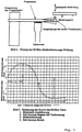
- the measured values for the deformation under thermal load are in 2 shown. Without the addition of phosphate (molding mixture 2.1), the test specimen is already deformed after a brief thermal load. Test specimens produced according to molding mixture 2.2, on the other hand, show a significantly improved thermal stability. By adding phosphate, the time until "hot deformation” and thus the "time until fracture” can be delayed.
- Example 2 To check the improved thermal stability of moldings shown in Example 2, cores were produced according to the molding mixtures 2.1 and 2.2. These cores were tested in a casting process (aluminum alloy, approx. 735°C) with regard to their thermal stability. It turned out that a circular segment of the molded body could only be reproduced correctly in the corresponding mold in the case of the mold material mixture 2.2 ( Figure 3b ). Without the addition of the phosphate component, elliptical deformations could be detected in the casting mold, schematized in Figure 3a shown.
Landscapes
- Engineering & Computer Science (AREA)
- Chemical & Material Sciences (AREA)
- Materials Engineering (AREA)
- Mechanical Engineering (AREA)
- General Health & Medical Sciences (AREA)
- Life Sciences & Earth Sciences (AREA)
- Health & Medical Sciences (AREA)
- Molecular Biology (AREA)
- Mold Materials And Core Materials (AREA)
- Molds, Cores, And Manufacturing Methods Thereof (AREA)
- Glass Compositions (AREA)
- Lubricants (AREA)
- Compositions Of Oxide Ceramics (AREA)
Description
- Die Erfindung betrifft die Verwendung einer Gießform für den Leichtmetallguss erhalten nach einem Verfahren und unter Verwendung einer Formstoffmischung nach Anspruch 1.
- Gießformen für die Herstellung von Metallkörpern werden im Wesentlichen in zwei Ausführungen hergestellt. Eine erste Gruppe bilden die so genannten Kerne oder Formen. Aus diesen wird die Gießform zusammengesetzt, welche im Wesentlichen die Negativform des herzustellenden Gussstücks darstellt. Eine zweite Gruppe bilden Hohlkörper, sog. Speiser, welche als Ausgleichsreservoir wirken. Diese nehmen flüssiges Metall auf, wobei durch entsprechende Maßnahmen dafür gesorgt wird, dass das Metall länger in der flüssigen Phase verbleibt, als das Metall, das sich in der die Negativform bildenden Gießform befindet. Erstarrt das Metall in der Negativform, kann flüssiges Metall aus dem Ausgleichsreservoir nachfließen, um die beim Erstarren des Metalls auftretende Volumenkontraktion auszugleichen.
- Gießformen bestehen aus einem feuerfesten Material, beispielsweise Quarzsand, dessen Körner nach dem Ausformen der Gießform durch ein geeignetes Bindemittel verbunden werden, um eine ausreichende mechanische Festigkeit der Gießform zu gewährleisten. Für die Herstellung von Gießformen verwendet man also einen feuerfesten Formgrundstoff, welcher mit einem geeigneten Bindemittel behandelt wurde. Der feuerfeste Formgrundstoff liegt bevorzugt in einer rieselfähigen Form vor, so dass er in eine geeignete Hohlform eingefüllt und dort verdichtet werden kann. Durch das Bindemittel wird ein fester Zusammenhalt zwischen den Partikeln des Formgrundstoffs erzeugt, so dass die Gießform die erforderliche mechanische Stabilität erhält.
- Gießformen müssen verschiedene Anforderungen erfüllen. Beim Gießvorgang selbst müssen sie zunächst eine ausreichende Stabilität und Temperaturbeständigkeit aufweisen, um das flüssige Metall in die aus einem oder mehreren Gieß(teil)formen gebildete Hohlform aufzunehmen. Nach Beginn des Erstarrungsvorgangs wird die mechanische Stabilität der Gießform durch eine erstarrte Metallschicht gewährleistet, die sich entlang der Wände der Hohlform ausbildet. Das Material der Gießform muss sich nun unter dem Einfluss der vom Metall abgegebenen Hitze in der Weise zersetzen, dass es seine mechanische Festigkeit verliert, also der Zusammenhalt zwischen einzelnen Partikeln des feuerfesten Materials aufgehoben wird. Dies wird erreicht, indem sich beispielsweise das Bindemittel unter Hitzeeinwirkung zersetzt. Nach dem Abkühlen wird das erstarrte Gussstück gerüttelt, wobei im Idealfall das Material der Gießformen wieder zu einem feinen Sand zerfällt, der sich aus den Hohlräumen der Metallform ausgießen lässt.
- Zur Herstellung der Gießformen können sowohl organische als auch anorganische Bindemittel eingesetzt werden, deren Aushärtung jeweils durch kalte oder heiße Verfahren erfolgen kann. Als kalte Verfahren bezeichnet man dabei Verfahren, welche im Wesentlichen bei Raumtemperatur ohne Erhitzen der Gießform durchgeführt werden. Die Aushärtung erfolgt dabei meist durch eine chemische Reaktion, die beispielsweise dadurch ausgelöst wird, dass ein Gas als Katalysator durch die zu härtende Form geleitet wird. Bei heißen Verfahren wird die Formstoffmischung nach der Formgebung auf eine ausreichend hohe Temperatur erhitzt, um beispielsweise das im Bindemittel enthaltene Lösungsmittel auszutreiben oder um eine chemische Reaktion zu initiieren, durch welche das Bindemittel beispielsweise durch Vernetzen ausgehärtet wird.
- Gegenwärtig werden für die Herstellung von Gießformen vielfach solche organischen Bindemittel eingesetzt, bei denen die Härtungsreaktion durch einen gasförmigen Katalysator beschleunigt wird oder die durch Reaktion mit einem gasförmigen Härter ausgehärtet werden. Diese Verfahren werden als "Cold-Box"-Verfahren bezeichnet.
- Ein Beispiel für die Herstellung von Gießformen unter Verwendung organischer Bindemittel ist das so genannte Ashland-Cold-Box-Verfahren. Es handelt sich dabei um ein Zweikomponenten-System. Die erste Komponente besteht aus der Lösung eines Polyols, meistens eines Phenolharzes. Die zweite Komponente ist die Lösung eines Polyisocyanates. So werden gemäß der
US 3,409,579 A die beiden Komponenten des Polyurethanbinders zur Reaktion gebracht, indem nach der Formgebung ein gasförmiges tertiäres Amin durch das Gemisch aus Formgrundstoff und Bindemittel geleitet wird. Bei der Aushärtereaktion von Polyurethanbindern handelt es sich um eine Polyaddition, d.h. eine Reaktion ohne Abspaltung von Nebenprodukten, wie z.B. Wasser. Zu den weiteren Vorteilen dieses Cold-Box-Verfahrens gehören gute Produktivität, Maßgenauigkeit der Gießformen sowie gute technische Eigenschaften, wie die Festigkeit der Gießformen, die Verarbeitungszeit des Gemisches aus Formgrundstoff und Bindemittel, usw. - Zu den heißhärtenden organischen Verfahren gehört das Hot-Box-Verfahren auf Basis von Phenol- oder Furanharzen, das Warm-Box-Verfahren auf Basis von Furanharzen und das Croning-Verfahren auf Basis von Phenol-Novolak-Harzen. Beim Hot-Box- sowie beim Warm-Box-Verfahren werden flüssige Harze mit einem latenten, erst bei erhöhter Temperatur wirksamen Härter zu einer Formstoffmischung verarbeitet. Beim Croning-Verfahren werden Formgrundstoffe, wie Quarz, Chromerz-, Zirkonsande, etc. bei einer Temperatur von ca. 100 bis 160°C mit einem bei dieser Temperatur flüssigen Phenol-Novolak-Harz umhüllt. Als Reaktionspartner für die spätere Aushärtung wird Hexamethylentetramin zugegeben. Bei den oben genannten heißhärtenden Technologien findet die Formgebung und Aushärtung in beheizbaren Werkzeugen statt, die auf eine Temperatur von bis zu 300°C aufgeheizt werden.
- Unabhängig vom Aushärtemechanismus ist allen organischen Systemen gemeinsam, dass sie sich beim Einfüllen des flüssigen Metalls in die Gießform thermisch zersetzen und dabei Schadstoffe, wie z.B. Benzol, Toluol, Xylole, Phenol, Formaldehyd und höhere, teilweise nicht identifizierte Crackprodukte freisetzen können. Es ist zwar durch verschiedene Maßnahmen gelungen, diese Emissionen zu minimieren, völlig vermeiden lassen sie sich bei organischen Bindemitteln jedoch nicht. Auch bei anorganischorganischen Hybridsystemen, die, wie die z.B. beim Resol-CO2-Verfahren eingesetzten Bindemittel, einen Anteil an organischen Verbindungen enthalten, treten solche unerwünschten Emissionen beim Gießen der Metalle auf.
- Um die Emission von Zersetzungsprodukten während des Gießvorgangs zu vermeiden, müssen Bindemittel verwendet werden, die auf anorganischen Materialien beruhen bzw. die höchstens einen sehr geringen Anteil an organischen Verbindungen enthalten. Solche Bindemittelsysteme sind bereits seit längerem bekannt. Es sind Bindemittelsysteme entwickelt worden, welche sich durch Einleitung von Gasen aushärten lassen. Ein derartiges System ist beispielsweise in der
GB 782 205 DE 199 25 167 wird eine exotherme Speisermasse beschreiben, die ein Alkalisilikat als Bindemittel enthält. Ferner sind Bindemittelsysteme entwickelt worden, welche bei Raumtemperatur selbsthärtend sind. Ein solches, auf Phosphorsäure und Metalloxiden beruhendes System ist z.B. in derUS 5,582,232 beschrieben. Schließlich sind noch anorganische Bindemittelsysteme bekannt, die bei höheren Temperaturen ausgehärtet werden, beispielsweise in einem heißen Werkzeug. Solche heißhärtenden Bindemittelsysteme sind beispielsweise aus derUS 5,474,606 bekannt, in welcher ein aus Alkaliwasserglas und Aluminiumsilikat bestehendes Bindemittelsystem beschrieben wird. - Anorganische Bindemittel weisen im Vergleich zu organischen Bindemitteln jedoch auch Nachteile auf. Beispielsweise besitzen die mit Wasserglas als Bindemittel hergestellten Gießformen eine relativ geringe Festigkeit. Dies führt insbesondere bei der Entnahme der Gießform aus dem Werkzeug zu Problemen, da die Gießform zerbrechen kann. Gute Festigkeiten zu diesem Zeitpunkt sind besonders wichtig für die Produktion komplizierter, dünnwandiger Formteile und deren sichere Handhabung. Der Grund für die niedrigen Festigkeiten besteht in erster Linie darin, dass die Gießformen noch Restwasser aus dem Bindemittel enthalten. Längere Verweilzeiten im heißen geschlossenen Werkzeug helfen nur bedingt, da der Wasserdampf nicht in ausreichendem Maß entweichen kann. Um eine möglichst vollständige Trocknung der Gießformen zu erreichen, wird in der
WO 98/06522 - Eine weitere Schwachstelle der bisher bekannten anorganischen Bindemittel ist die geringe Stabilität der damit hergestellten Gießformen gegen hohe Luftfeuchtigkeit. Damit ist eine Lagerung der Formkörper über einen längeren Zeitraum, wie bei organischen Bindemitteln üblich, nicht gesichert möglich.
- In der
EP 1 122 002 wird ein Verfahren beschrieben, das sich zur Herstellung von Gießformen für den Metallguss eignet. Zur Herstellung des Bindemittels wird ein Alkalihydroxid, insbesondere Natronlauge, mit einem teilchenförmigen Metalloxid vermischt, welches in Gegenwart der Alkalilauge ein Metallat ausbilden kann. Die Teilchen werden getrocknet, nachdem sich am Rand der Teilchen eine Schicht aus dem Metallat ausgebildet hat. Im Kern der Teilchen verbleibt ein Abschnitt, in welchem das Metalloxid nicht umgesetzt wurde. Als Metalloxid wird vorzugsweise ein disperses Siliciumdioxid oder auch feinteiliges Titanoxid oder Zinkoxid verwendet. - In der
WO 94/14555 - In der
EP 1 095 719 A2 wird ein Bindemittelsystem für Formsande zur Herstellung von Kernen beschrieben. Das Bindemittelsystem auf Wasserglasbasis besteht aus einer wässrigen Alkalisilikatlösung und einer hygroskopischen Base, wie beispielsweise Natriumhydroxid, die im Verhältnis 1:4 bis 1:6 zugesetzt wird. Das Wasserglas weist ein Modul SiO2/M2O von 2,5 bis 3,5 und einen Feststoffanteil von 20 bis 40 % auf. Um eine rieselfähige Formstoffmischung zu erhalten, welche auch in komplizierte Kernformen eingefüllt werden kann, sowie zur Steuerung der hygroskopischen Eigenschaften, enthält das Bindemittelsystem noch einen oberflächenaktiven Stoff, wie Silikonöl, das einen Siedepunkt ≥ 250°C aufweist. Das Bindemittelsystem wird mit einem geeigneten Feuerfeststoff, wie Quarzsand, vermischt und kann dann mit einer Kernschießmaschine in einen Kernkasten eingeschossen werden. Die Aushärtung der Formstoffmischung erfolgt durch Entzug des noch enthaltenen Wassers. Die Trocknung bzw. Aushärtung der Gießform kann auch unter Einwirkung von Mikrowellen erfolgen. - Um höhere Anfangsfestigkeiten, eine bessere Beständigkeit der Gießform gegen Luftfeuchtigkeit und beim Guss ein besseres Ergebnis bei der Oberfläche des Gusstücks zu erhalten, wird in der
WO 2006/024540 A2 eine Formstoffmischung vorgeschlagen, welche neben einem feuerfesten Formgrundstoff ein auf Wasserglas basierendes Bindemittel enthält. Der Formstoffmischung ist ein Anteil eines teilchenförmigen Metalloxids zugesetzt. Bevorzugt wird als teilchenförmiges Metalloxid Fällungskieselsäure oder pyrogene Kieselsäure verwendet. - In der
EP 0 796 681 A2 wird ein anorganisches Bindemittel für die Herstellung von Gießformen beschrieben, welches in gelöster Form ein Silikat sowie ein Phosphat enthält. Als Phosphate werden bevorzugt Polyphosphate der Formel ((PO3)n) verwendet, wobei n der mittleren Kettenlänge entspricht und Werte von 3 bis 32 annehmen kann. Das Bindemittel wird mit einem feuerfesten Formgrundstoff vermischt und dann zu einer Gießform geformt. Das Aushärten der Gießform erfolgt durch Erhitzen der Form auf Temperaturen von etwa 120 °C unter Durchblasen von Luft. Die auf diese Weise hergestellten Testformen zeigen eine hohe Heißfestigkeit nach der Entnahme aus der Form wie auch eine hohe Kaltfestigkeit. Ein Nachteil sind hierbei jedoch die Anfangsfestigkeiten, mit denen eine prozesssichere Serienkernfertigung nicht gewährleistet werden kann. Auch die thermische Stabilität ist für die Anwendung bei Temperaturen oberhalb 500°C, insbesondere bei thermisch stark beanspruchten Formen, unzureichend. - Wegen des oben diskutierten Problems der beim Gießen auftretenden gesundheitsschädlichen Emissionen ist man bemüht, bei der Herstellung von Gießformen auch bei komplizierten Geometrien die organischen Bindemittel durch anorganische Bindemittel zu ersetzen. Werden jedoch Gießformen hergestellt, die sehr dünnwandige Segmente umfassen, wird beim Gießvorgang oft eine Deformation dieser dünnwandigen Abschnitte beobachtet. Dies kann zu Abweichungen in den Abmessungen des Gusstücks führen, die durch nachträgliche Bearbeitung nicht mehr ausgeglichen werden können. Das Gusstück wird damit unbrauchbar. Dünnwandige Abschnitte der Gießform werden beim Guss thermisch stärker belastet als dickwandige Abschnitte und neigen daher eher zur Deformation. Dieses Problem tritt bereits beim Aluminiumguss auf, wobei hier im Vergleich zum Eisen- oder Stahlguss mit etwa 650 - 750 °C relativ niedrige Temperaturen herrschen. Besonders problematisch wird dies, wenn das flüssige Metall beim Einfüllen in die Gießform unter einem Neigungswinkel auf die thermisch hoch belasteten dünnwandigen Abschnitte trifft und durch den metallostatischen Druck hohe mechanische Kräfte auf die dünnwandigen Abschnitte einwirken.
- Der Erfindung lag daher die Aufgabe zugrunde, eine Formstoffmischung zur Herstellung von Gießformen für den Leichtmetallguss zur Verfügung zu stellen, welche mindestens einen feuerfesten Formgrundstoff sowie ein auf Wasserglas basierendes Bindemittelsystem umfasst, wobei die Formstoffmischung einen Anteil eines teilchenförmigen Metalloxids enthält, welches ausgewählt ist aus der Gruppe von Siliciumdioxid, Aluminiumoxid, Titanoxid und Zinkoxid, welche die Herstellung von Gießformen ermöglicht, die dünnwandige Abschnitte umfassen, wobei beim Metallguss die dünnwandigen Abschnitte keine Deformation zeigen.
- Diese Aufgabe wird durch die Verwendung mit den Merkmalen des Patentanspruchs 1 gelöst. Vorteilhafte Weiterbildungen der erfindungsgemäßen Verwendung sind Gegenstand der abhängigen Patentansprüche.
- Überraschend wurde gefunden, dass durch den Zusatz einer phosphorhaltigen Verbindung nach Anspruch 1 die Festigkeit der Gießform soweit erhöht werden kann, dass auch dünnwandige Abschnitte verwirklicht werden können, die beim Metallguss keine Deformation erfahren. Dies gilt auch dann, wenn das flüssige Metall beim Guss unter einem Winkel auf die Oberfläche der dünnwandigen Abschnitte der Gießform trifft und daher starke mechanische Kräfte auf den dünnwandigen Abschnitt der Gießform einwirken. Dadurch können auch Gießformen mit sehr komplexer Geometrie unter Verwendung anorganischer Bindemittel hergestellt werden, sodass auch für diese Anwendungen auf die Verwendung organischer Bindemittel verzichtet werden kann.
- Die erfindungsgemäße Verwendung ist durch Anspruch 1 gekennzeichnet.
- Die Formstoffmischung enthält als weiteren Bestandteil eine phosphorhaltige Verbindung, wobei der Anteil der phosphorhaltigen Verbindung, bezogen auf den feuerfesten Formgrundstoff, zwischen 0,05 und 0,5 Gew.-% gewählt ist, und die phosphorhaltige Verbindung ein Natrium-Metaphosphat oder ein Natrium-Polyphosphat ist.
- Als feuerfester Formgrundstoff können für die Herstellung von Gießformen übliche Materialien verwendet werden. Der feuerfeste Formgrundstoff muss bei den beim Metallguss herrschenden Temperaturen eine ausreichende Formbeständigkeit aufweisen. Ein geeigneter feuerfester Formgrundstoff zeichnet sich daher durch einen hohen Schmelzpunkt aus. Der Schmelzpunkt des feuerfesten Formgrundstoffs liegt vorzugsweise höher als 700°C, bevorzugt höher als 800 °C, besonders bevorzugt höher als 900 °C und insbesondere bevorzugt höher als 1000 °C. Als feuerfester Formgrundstoffe sind beispielsweise Quarz- oder Zirkonsand geeignet. Weiter sind auch faserförmige feuerfeste Formgrundstoffe geeignet, wie beispielsweise Schamottefasern. Weitere geeignete feuerfeste Formgrundstoffe sind beispielsweise Olivin, Chromerzsand, Vermiculit.
- Weiter können als feuerfeste Formgrundstoffe auch künstliche feuerfeste Formgrundstoffe verwendet werden, wie z.B. Aluminiumsilikathohlkugeln (sog. Microspheres), Glasperlen, Glasgranulat oder unter der Bezeichnung "Cerabeads®" bzw. "Carboaccucast®" bekannte kugelförmige keramische Formgrundstoffe. Diese künstlichen feuerfesten Formgrundstoffe werden synthetisch hergestellt oder fallen beispielsweise als Abfall in industriellen Prozessen an. Diese kugelförmigen keramischen Formgrundstoffe enthalten als Mineralien beispielsweise Mullit, Korund, β-Cristobalit in unterschiedlichen Anteilen. Sie enthalten als wesentliche Anteile Aluminiumoxid und Siliciumdioxid. Typische Zusammensetzungen enthalten beispielsweise Al2O3 und SiO2 in etwa gleichen Anteilen. Daneben können noch weitere Bestandteile in Anteilen von < 10 % enthalten sein, wie TiO2, Fe2O3. Der Durchmesser der kugelförmigen feuerfesten Formgrundstoffe beträgt vorzugsweise weniger als 1000 µm, insbesondere weniger als 600 µm. Geeignet sind auch synthetisch hergestellte feuerfeste Formgrundstoffe, wie beispielsweise Mullit (x Al2O3 · y SiO2, mit x = 2 bis 3, y = 1 bis 2; ideale Formel: Al2SiO5). Diese künstlichen Formgrundstoffe gehen nicht auf einen natürlichen Ursprung zurück und können auch einem besonderen Formgebungsverfahren unterworfen worden sein, wie beispielsweise bei der Herstellung von Aluminiumsilikatmikrohohlkugeln, Glasperlen oder kugelförmigen keramischen Formgrundstoffen. Aluminiumsilikatmikrohohlkugeln entstehen beispielsweise bei der Verbrennung fossiler Brennstoffe oder anderer brennbarer Materialien und werden aus der bei der Verbrennung entstehenden Asche abgetrennt. Mikrohohlkugeln als künstlicher feuerfester Formgrundstoff zeichnen sich durch ein niedriges spezifisches Gewicht aus. Dies geht zurück auf die Struktur dieser künstlichen feuerfesten Formgrundstoffe, welche gasgefüllte Poren umfassen. Diese Poren können offen oder geschlossen sein. Bevorzugt werden geschlossenporige künstliche feuerfeste Formgrundstoffe verwendet. Bei Verwendung offenporiger künstlicher feuerfester Formgrundstoffe wird ein Teil des auf Wasserglas basierenden Bindemittels in den Poren aufgenommen und kann dann keine Bindewirkung mehr entfalten.
- Gemäß einer Ausführungsform werden als künstliche Formgrundstoffe Glasmaterialien verwendet. Diese werden insbesondere entweder als Glaskugeln oder als Glasgranulat eingesetzt. Als Glas können übliche Gläser verwendet werden, wobei Gläser, die einen hohen Schmelzpunkt zeigen, bevorzugt sind. Geeignet sind beispielsweise Glasperlen und/oder Glasgranulat, das aus Glasbruch hergestellt wird. Ebenfalls geeignet sind Boratgläser. Die Zusammensetzung derartiger Gläser ist beispielhaft in der nachfolgenden Tabelle angegeben.
Tabelle: Zusammensetzung von Gläsern Bestandteil Glasbruch Boratglas SiO2 50 - 80 % 50 - 80 % Al2O3 0 -15 % 0 - 15 % Fe2O3 < 2 % < 2 % MIIO 0 - 25 % 0 - 25 % MI 2O 5 - 25 % 1 - 10 % B2O3 < 15 % Sonst. < 10 % < 10 % MII : Erdalkalimetall, z.B. Mg, Ca, Ba MI : Alkalimetall, z.B. Na, K - Neben den in der Tabelle aufgeführten Gläsern können jedoch auch andere Gläser verwendet werden, deren Gehalt an den oben genannten Verbindungen außerhalb der genannten Bereiche liegt. Ebenso können auch Spezialgläser verwendet werden, die neben den genannten Oxiden auch andere Elemente bzw. deren Oxide enthalten.
- Der Durchmesser der Glaskugeln beträgt vorzugsweise 1 bis 1000 µm, bevorzugt 5 bis 500 µm und besonders bevorzugt 10 bis 400 µm.
- Bevorzugt wird lediglich ein Teil des feuerfesten Formgrundstoffs durch Glasmaterialien gebildet. Der Anteil des Glasmaterials am feuerfesten Formgrundstoff wird bevorzugt geringer als 35 Gew.-%, besonders bevorzugt geringer als 25 Gew.-%, insbesondere bevorzugt geringer als 15 Gew.-% gewählt.
- In Gießversuchen mit Aluminium wurde gefunden, dass bei Verwendung künstlicher Formgrundstoffe, vor allem bei Glasperlen, Glasgranulat bzw. Microspheres aus Glas, nach dem Gießen weniger Formsand an der Metalloberfläche haften bleibt als bei Verwendung von reinem Quarzsand. Der Einsatz derartiger künstlicher Formgrundstoffe auf Basis von Glasmaterialien ermöglicht daher die Erzeugung glatter Gussoberflächen, wobei eine aufwändige Nachbehandlung durch Strahlen nicht oder zumindest in erheblich geringerem Ausmaß erforderlich ist.
- Um den beschriebenen Effekt der Erzeugung glatter Gussoberflächen zu erhalten, wird der Anteil des Glasmaterials am feuerfesten Formgrundstoff vorzugsweise größer als 0,5 Gew.-%, bevorzugt größer als 1 Gew.-%, besonders bevorzugt größer als 1,5 Gew.-%, insbesondere bevorzugt größer als 2 Gew.-% gewählt.
- Es ist nicht notwendig, den gesamten feuerfesten Formgrundstoff aus den künstlichen feuerfesten Formgrundstoffen zu bilden. Der bevorzugte Anteil der künstlichen Formgrundstoffe liegt bei mindestens etwa 3 Gew.-%, besonders bevorzugt mindestens 5 Gew.-%, insbesondere bevorzugt mindestens 10 Gew.-%, vorzugsweise bei mindestens etwa 15 Gew.-%, besonders bevorzugt bei mindestens etwa 20 Gew.-%, bezogen auf die gesamte Menge des feuerfesten Formgrundstoffs. Der feuerfeste Formgrundstoff weist vorzugsweise einen rieselfähigen Zustand auf, so dass die Formstoffmischung in üblichen Kernschießmaschinen verarbeitet werden kann.
- Aus Kostengründen wird der Anteil der künstlichen feuerfesten Formgrundstoffe gering gehalten. Bevorzugt beträgt der Anteil der künstlichen feuerfesten Formgrundstoffe am feuerfesten Formgrundstoff weniger als 80 Gew.-%, vorzugsweise weniger als 75 Gew.-%, besonders bevorzugt weniger als 65 Gew.-%.
- Als weitere Komponente umfasst die Formstoffmischung ein auf Wasserglas basierendes Bindemittel. Als Wasserglas können dabei übliche Wassergläser verwendet werden, wie sie bereits bisher als Bindemittel in Formstoffmischungen verwendet werden. Diese Wassergläser enthalten gelöste Natrium- oder Kaliumsilikate und können durch Lösen von glasartigen Kalium- und Natriumsilikaten in Wasser hergestellt werden. Das Wasserglas weist vorzugsweise ein Modul SiO2/M2O im Bereich von 1,6 bis 4,0, insbesondere 2,0 bis 3,5, auf, wobei M für Natrium und/oder Kalium steht. Die Wassergläser weisen vorzugsweise einen Feststoffanteil im Bereich von 30 bis 60 Gew.-% auf. Der Feststoffanteil bezieht sich auf die im Wasserglas enthaltene Menge an SiO2 und M2O.
- Weiter enthält die Formstoffmischung einen Anteil eines teilchenförmigen Metalloxids, welches synthetisch hergestelltes amorphes Siliciumdioxid ist. Die durchschnittliche Primärpartikelgröße des teilchenförmigen Metalloxids kann zwischen 0,10 µm und 1 µm betragen. Wegen der Agglomeration der Primärpartikel beträgt jedoch die Teilchengröße der Metalloxide vorzugsweise weniger als 300 µm, bevorzugt weniger als 200 µm, insbesondere bevorzugt weniger als 100 µm. Sie liegt bevorzugt im Bereich von 5 bis 90 µm, insbesondere bevorzugt 10 bis 80 µm und ganz besonders bevorzugt im Bereich von 15 bis 50 µm. Die Teilchengröße lässt sich beispielsweise durch Siebanalyse bestimmen. Besonders bevorzugt beträgt der Siebrückstand auf einem Sieb mit einer Maschenweite von 63 µm weniger als 10 Gew.-%, vorzugsweise weniger als 8 Gew.-%.
- Als teilchenförmiges Siliciumdioxid wird vorzugsweise Fällungskieselsäure und/oder pyrogene Kieselsäure verwendet. Fällungskieselsäure wird durch Reaktion einer wässrigen Alkalisilikatlösung mit Mineralsäuren erhalten. Der dabei anfallende Niederschlag wird anschließend abgetrennt, getrocknet und vermahlen. Unter pyrogenen Kieselsäuren werden Kieselsäuren verstanden, die bei hohen Temperaturen durch Koagulation aus der Gasphase gewonnen werden. Die Herstellung pyrogener Kieselsäure kann beispielsweise durch Flammhydrolyse von Siliciumtetrachlorid oder im Lichtbogenofen durch Reduktion von Quarzsand mit Koks oder Anthrazit zu Siliciummonoxidgas mit anschließender Oxidation zu Siliciumdioxid erfolgen. Die nach dem Lichtbogenofen-Verfahren hergestellten pyrogenen Kieselsäuren können noch Kohlenstoff enthalten. Fällungskieselsäure und pyrogene Kieselsäure sind für die Formstoffmischung gleich gut geeignet. Diese Kieselsäuren werden im Weiteren als "synthetisches amorphes Siliciumdioxid" bezeichnet.
- Die Erfinder nehmen an, dass das stark alkalische Wasserglas mit den an der Oberfläche des synthetisch hergestellten amorphen Siliciumdioxids angeordneten Silanolgruppen reagieren kann und dass beim Verdampfen des Wassers eine intensive Verbindung zwischen dem Siliciumdioxid und dem dann festen Wasserglas hergestellt wird.
- Als wesentliche weitere Komponente enthält die Formstoffmischung eine phosphorhaltige Verbindung und der Anteil der phosphorhaltigen Verbindung, bezogen auf den feuerfesten Formgrundstoff, zwischen 0,05 und 0,5 Gew.-% gewählt ist, und die phosphorhaltige Verbindung ein Natrium-Metaphosphat oder ein Natrium-Polyphosphat ist, nachfolgend auch nur kurz das Phosphat.
- Unter Polyphosphaten werden insbesondere lineare Phosphate verstanden, die mehr als ein Phosphoratom umfassen, wobei die Phosphoratome jeweils über Sauerstoffbrücken verbunden sind. Polyphosphate werden durch Kondensation von Orthophosphationen unter Wasserabspaltung erhalten, sodass eine lineare Kette von PO4-Tetraedern erhalten wird, die jeweils über Ecken verbunden sind. Polyphosphate weisen die allgemeine Formel (O(PO3)n)(n+2)- auf, wobei n der Kettenlänge entspricht. Ein Polyphosphat kann bis zu mehreren hundert PO4-Tetraeder umfassen. Bevorzugt werden jedoch Polyphosphate mit kürzeren Kettenlängen eingesetzt. Bevorzugt weist n Werte von 2 bis 100, insbesondere bevorzugt 5 bis 50 auf. Es können auch höher kondensierte Polyphosphate verwendet werden, d.h. Polyphosphate, in welchen die PO4-Tetraeder über mehr als zwei Ecken miteinander verbunden sind und daher eine Polymerisation in zwei bzw. drei Dimensionen zeigen.
- Unter Metaphosphaten werden zyklische Strukturen verstanden, die aus PO4-Tetraedern aufgebaut sind, die jeweils über Ecken verbunden sind. Metaphosphate weisen die allgemeine Formel ((PO3)n)n- auf, wobei n mindestens 3 beträgt. Bevorzugt weist n Werte von 3 bis 10 auf.
- Es können sowohl einzelne Phosphate verwendet werden als auch Gemische aus verschiedenen Phosphaten.
- Der Anteil der phosphorhaltigen Verbindung, bezogen auf den feuerfesten Formgrundstoff, beträgt zwischen 0,05 und 0,5 Gew.-%. Bei einem Anteil von weniger als 0,05 Gew.-% ist kein deutlicher Einfluss auf die Formbeständigkeit der Gießform festzustellen. Übersteigt der Anteil des Phosphats 1,0 Gew.-%, nimmt die Heißfestigkeit der Gießform stark ab.
- Die phosphorhaltige Verbindung kann an sich in fester oder gelöster Form der Formstoffmischung zugesetzt sein. Bevorzugt ist die phosphorhaltige Verbindung der Formstoffmischung als Feststoff zugesetzt. Wird die phosphorhaltige Verbindung in gelöster Form zugegeben, ist Wasser als Lösungsmittel bevorzugt.
- Als weiterer Vorteil eines Zusatzes phosphorhaltiger Verbindungen zu Formstoffmischungen zur Herstellung von Gießformen wurde gefunden, dass die Formen nach dem Metallguss einen sehr guten Zerfall zeigen. Dies trifft für Metalle zu, die niedrigere Gießtemperaturen benötigen, wie Leichtmetalle, insbesondere Aluminium. Beim Eisenguss wirken höhere Temperaturen von mehr als 1200°C auf die Gießform ein, sodass eine erhöhte Gefahr eines Verglasens der Gießform und damit einer Verschlechterung der Zerfallseigenschaften besteht.
- Im Rahmen der von den Erfindern durchgeführten Untersuchungen zur Stabilität und zum Zerfall von Gießformen wurde auch Eisenoxid als mögliches Additiv in Betracht gezogen. Bei Zusatz von Eisenoxid zur Formstoffmischung wird ebenfalls eine Steigerung der Stabilität der Gießform beim Metallguss beobachtet. Durch den Zusatz von Eisenoxid lässt sich also potentiell ebenfalls die Stabilität dünnwandiger Abschnitte der Gießform verbessern. Der Zusatz von Eisenoxid bewirkt jedoch nicht die beim Zusatz phosphorhaltiger Verbindungen beobachtete Verbesserung der Zerfallseigenschaften der Gießform nach dem Metallguss.
- Die Formstoffmischung stellt eine intensive Mischung aus zumindest den genannten Bestandteilen dar. Dabei sind die Teilchen des feuerfesten Formgrundstoffs vorzugsweise mit einer Schicht des Bindemittels überzogen. Durch Verdampfen des im Bindemittel vorhandenen Wassers (ca. 40 - 70 Gew.-%, bezogen auf das Gewicht des Bindemittels) kann dann ein fester Zusammenhalt zwischen den Teilchen des feuerfesten Formgrundstoffs erreicht werden.
- Das Bindemittel, d.h. das Wasserglas sowie das teilchenförmige Metalloxid, nämlich synthetisches amorphes Siliciumdioxid, und das Phosphat ist in der Formstoffmischung bevorzugt in einem Anteil von weniger als 20 Gew.-% enthalten. Der Anteil des Bindemittels bezieht sich dabei auf den Feststoffanteil des Bindemittels. Werden massive feuerfeste Formgrundstoffe verwendet, wie beispielsweise Quarzsand, ist das Bindemittel vorzugsweise in einem Anteil von weniger als 10 Gew.-%, bevorzugt weniger als 8 Gew.-%, insbesondere bevorzugt weniger als 5 Gew.-% enthalten. Werden feuerfeste Formgrundstoffe verwendet, welche eine geringe Dichte aufweisen, wie beispielsweise die oben beschriebenen Mikrohohlkugeln, erhöht sich der Anteil des Bindemittels entsprechend.
- Das teilchenförmige Metalloxid, nämlich das synthetische amorphe Siliciumdioxid, ist, bezogen auf das Gesamtgewicht des Bindemittels, vorzugsweise in einem Anteil von 2 bis 80 Gew.-% enthalten, vorzugsweise zwischen 3 und 60 Gew.-%, insbesondere bevorzugt zwischen 4 und 50 Gew.-%.
- Das Verhältnis von Wasserglas zu teilchenförmigem Metalloxid, nämlich synthetischem amorphem Siliciumdioxid, kann innerhalb weiter Bereiche variiert werden. Dies bietet den Vorteil, die Anfangsfestigkeit der Gießform, d.h. die Festigkeit unmittelbar nach Entnahme aus dem heißen Werkzeug, und die Feuchtigkeitsbeständigkeit zu verbessern, ohne die Endfestigkeiten, d.h. die Festigkeiten nach dem Erkalten der Gießform, gegenüber einem Wasserglasbindemittel ohne amorphes Siliciumdioxid wesentlich zu beeinflussen. Dies ist vor allem im Leichtmetallguss von großem Interesse. Auf der einen Seite sind hohe Anfangsfestigkeiten erwünscht, um nach der Herstellung der Gießform diese problemlos transportieren oder mit anderen Gießformen zusammensetzen zu können. Auf der anderen Seite sollte die Endfestigkeit nach dem Aushärten nicht zu hoch sein, um Schwierigkeiten beim Binderzerfall nach dem Abguss zu vermeiden, d.h. der Formgrundstoff sollte nach dem Gießen problemlos aus Hohlräumen der Gussform entfernt werden können.
- Der in der Formstoffmischung enthaltene Formgrundstoff kann in einer Ausführungsform der Erfindung zumindest einen Anteil von Mikrohohlkugeln enthalten. Der Durchmesser der Mikrohohlkugeln liegt normalerweise im Bereich von 5 bis 500 µm, vorzugsweise im Bereich von 10 bis 350 µm und die Dicke der Schale liegt gewöhnlich im Bereich von 5 bis 15 % des Durchmessers der Mikrokugeln. Diese Mikrokugeln weisen ein sehr geringes spezifisches Gewicht auf, so dass die unter Verwendung von Mikrohohlkugeln hergestellten Gießformen ein niedriges Gewicht aufweisen. Besonders vorteilhaft ist die Isolierwirkung der Mikrohohlkugeln. Die Mikrohohlkugeln werden daher insbesondere dann für die Herstellung von Gießformen verwendet, wenn diese eine erhöhte Isolierwirkung aufweisen sollen. Solche Gießformen sind beispielsweise die bereits in der Einleitung beschriebenen Speiser, welche als Ausgleichsreservoir wirken und flüssiges Metall enthalten, wobei das Metall solange in einem flüssigen Zustand gehalten werden soll, bis das in die Hohlform eingefüllte Metall erstarrt ist. Ein anderes Anwendungsgebiet von Gießformen, welche Mikrohohlkugeln enthalten, sind beispielsweise Abschnitte einer Gießform, welche besonders dünnwandigen Abschnitten der fertigen Gussform entsprechen. Durch die isolierende Wirkung der Mikrohohlkugeln wird sichergestellt, dass das Metall in den dünnwandigen Abschnitten nicht vorzeitig erstarrt und damit die Wege innerhalb der Gießform verstopft.
- Werden Mikrohohlkugeln verwendet, wird das Bindemittel, bedingt durch die geringe Dichte dieser Mikrohohlkugeln, vorzugsweise in einem Anteil im Bereich von vorzugsweise weniger als 20 Gew.-%, insbesondere bevorzugt im Bereich von 10 bis 18 Gew.-% verwendet. Die Werte beziehen sich auf den Feststoffanteil des Bindemittels.
- Die Mikrohohlkugeln weisen bevorzugt eine ausreichende Temperaturstabilität auf, sodass sie beim Metallguss nicht vorzeitig erweichen und ihre Form verlieren. Die Mikrohohlkugeln bestehen vorzugsweise aus einem Aluminiumsilikat. Diese Aluminiumsilikatmikrohohlkugeln weisen vorzugsweise einen Gehalt an Aluminiumoxid von mehr als 20 Gew.-% auf, können jedoch auch einen Gehalt von mehr als 40 Gew.-% aufweisen. Solche Mikrohohlkugeln werden beispielsweise von der Omega Minerals Germany GmbH, Norderstedt, unter den Bezeichnungen Omega-Spheres® SG mit einem Aluminiumoxidgehalt von ca. 28 - 33 %, Omega-Spheres® WSG mit einem Aluminiumoxidgehalt von ca. 35 - 39 % und E-Spheres® mit einem Aluminiumoxidgehalt von ca. 43 % in den Handel gebracht. Entsprechende Produkte sind bei der PQ Corporation (USA) unter der Bezeichnung "Extendospheres®" erhältlich.
- Gemäß einer weiteren Ausführungsform werden Mikrohohlkugeln als feuerfester Formgrundstoff verwendet, welche aus Glas aufgebaut sind.
- Gemäß einer bevorzugten Ausführungsform bestehen die Mikrohohlkugeln aus einem Borsilikatglas. Das Borsilikatglas weist dabei einen Anteil an Bor, berechnet als B2O3, von mehr als 3 Gew.-% auf. Der Anteil der Mikrohohlkugeln wird vorzugsweise kleiner als 20 Gew.-% gewählt, bezogen auf die Formstoffmischung. Bei Verwendung von Borsilikatglas-Mikrohohlkugeln wird bevorzugt ein geringer Anteil gewählt. Dieser beträgt vorzugsweise weniger als 5 Gew.-%, bevorzugt weniger als 3 Gew.-%, und liegt insbesondere bevorzugt im Bereich von 0,01 bis 2 Gew.-%.
- Wie bereits erläutert, enthält die Formstoffmischung in einer bevorzugten Ausführungsform zumindest einen Anteil an Glasgranulat und/oder Glasperlen als feuerfesten Formgrundstoff.
- Es ist auch möglich, die Formstoffmischung als exotherme Formstoffmischung auszubilden, die beispielsweise für die Herstellung exothermer Speiser geeignet ist. Dazu enthält die Formstoffmischung ein oxidierbares Metall und ein geeignetes Oxidationsmittel. Bezogen auf die Gesamtmasse der Formstoffmischung bilden die oxidierbaren Metalle bevorzugt einen Anteil von 15 bis 35 Gew.-%. Das Oxidationsmittel wird bevorzugt in einem Anteil von 20 bis 30 Gew.-%, bezogen auf die Formstoffmischung zugesetzt. Geeignete oxidierbare Metalle sind beispielsweise Aluminium oder Magnesium. Geeignete Oxidationsmittel sind beispielsweise Eisenoxid oder Kaliumnitrat.
- Bindemittel, welche Wasser enthalten, weisen im Vergleich zu Bindemitteln auf Basis organischer Lösungsmittel eine schlechtere Fließfähigkeit auf. Die Fließfähigkeit der Formstoffmischung kann sich durch den Zusatz des teilchenförmigen Metalloxids weiter verschlechtern. Dies bedeutet, dass sich Formwerkzeuge mit engen Durchgängen und mehreren Umlenkungen schlechter füllen lassen. Als Folge davon besitzen die Gießformen Abschnitte mit ungenügender Verdichtung, was wiederum beim Abguss zu Gussfehlern führen kann. Gemäß einer vorteilhaften Ausführungsform enthält die Formstoffmischung einen Anteil eines Schmiermittels, bevorzugt eines plättchenförmigen Schmiermittels, insbesondere Grafit, MoS2, Talkum und/oder Pyrophillit. Überraschend hat sich gezeigt, dass bei einem Zusatz derartiger Schmiermittel, insbesondere von Grafit, auch komplexe Formen mit dünnwandigen Abschnitten hergestellt werden können, wobei die Gießformen durchgängig eine gleichmäßig hohe Dichte und Festigkeit aufweisen, so dass beim Gießen im Wesentlichen keine Gussfehler beobachtet werden. Die Menge des zugesetzten plättchenförmigen Schmiermittels, insbesondere Grafits, beträgt vorzugsweise 0,05 Gew.-% bis 1 Gew.-%, bezogen auf den feuerfesten Formgrundstoff.
- Neben den genannten Bestandteilen kann die Formstoffmischung noch weitere Zusätze umfassen. Beispielsweise können interne Trennmittel zugesetzt werden, welche die Ablösung der Gießformen aus dem Formwerkzeug erleichtern. Geeignete interne Trennmittel sind z.B. Calciumstearat, Fettsäureester, Wachse, Naturharze oder spezielle Alkydharze. Weiter können auch Silane zur Formstoffmischung gegeben werden.
- So enthält die Formstoffmischung in einer bevorzugten Ausführungsform ein organisches Additiv, welches einen Schmelzpunkt im Bereich von 40 bis 180 °C, vorzugsweise 50 bis 175 °C aufweist, also bei Raumtemperatur fest ist. Unter organischen Additiven werden dabei Verbindungen verstanden, deren Molekülgerüst überwiegend aus Kohlenstoffatomen aufgebaut ist, also beispielsweise organische Polymere. Durch die Zugabe der organischen Additive kann die Güte der Oberfläche des Gussstücks weiter verbessert werden. Der Wirkmechanismus der organischen Additive ist nicht geklärt. Ohne an diese Theorie gebunden sein zu wollen nehmen die Erfinder jedoch an, dass zumindest ein Teil der organischen Additive beim Gießvorgang verbrennt und dabei ein dünnes Gaspolster zwischen flüssigem Metall und dem die Wand der Gießform bildenden Formgrundstoff entsteht und so eine Reaktion zwischen flüssigem Metall und Formgrundstoff verhindert wird. Ferner nehmen die Erfinder an, dass ein Teil der organischen Additive unter der beim Gießen herrschenden reduzierenden Atmosphäre eine dünne Schicht von so genanntem Glanzkohlenstoff bildet, der ebenfalls eine Reaktion zwischen Metall und Formgrundstoff verhindert. Als weitere vorteilhafte Wirkung kann durch die Zugabe der organischen Additive eine Steigerung der Festigkeit der Gießform nach dem Aushärten erreicht werden.
- Die organischen Additive werden bevorzugt in einer Menge von 0,01 bis 1,5 Gew.-%, insbesondere bevorzugt 0,05 bis 1,3 Gew.-%, besonders bevorzugt 0,1 bis 1,0 Gew.-%, jeweils bezogen auf den feuerfesten Formgrundstoff, zugegeben. Um eine starke Rauchentwicklung während des Metallgusses zu vermeiden, wird der Anteil an organischen Additiven meist geringer als 0,5 Gew.-% gewählt.
- Überraschend wurde gefunden, dass eine Verbesserung der Oberfläche des Gussstücks mit sehr unterschiedlichen organischen Additiven erreicht werden kann. Geeignete organische Additive sind beispielsweise Phenol-Formaldehydharze, wie z.B. Novolake, Epoxidharze, wie beispielsweise Bisphenol-A-Epoxidharze, Bisphenol-F-Epoxidharze oder epoxidierte Novolake, Polyole, wie beispielsweise Polyethylenglykole oder Polypropylenglykole, Polyolefine, wie beispielsweise Polyethylen oder Polypropylen, Copolymere aus Olefinen, wie Ethylen oder Propylen, und weiteren Comonomeren, wie Vinylacetat, Polyamide, wie beispielsweise Polyamid-6, Polyamid-12 oder Polyamid-6,6, natürliche Harze, wie beispielsweise Balsamharz, Fettsäuren, wie beispielsweise Stearinsäure, Fettsäureester, wie beispielsweise Cetylpalmitat, Fettsäureamide, wie beispielsweise Ethylendiaminbisstearamid, monomere oder polymere Kohlenhydratverbindungen, wie etwa Glucose oder Cellulose, und deren Derivate, wie etwa Methyl-, Ethyl- oder Carboxymethylcellulose, sowie Metallseifen, wie beispielsweise Stearate oder Oleate'ein- bis dreiwertiger Metalle. Die organischen Additive können sowohl als reiner Stoff enthalten sein, als auch als Gemisch verschiedener organischer Verbindungen.
- Gemäß einer weiteren bevorzugten Ausführungsform enthält die Formstoffmischung einen Anteil zumindest eines Silans. Geeignete Silane sind beispielsweise Aminosilane, Epoxysilane, Mercaptosilane, Hydroxysilane, Methacrylsilane, Ureidosilane und Polysiloxane. Beispiele für geeignete Silane sind γ-Aminopropyltrimethoxysilan, γ-Hydroxypropyltrimethoxysilan, 3-Ureidopropyltriethoxysilan, γ-Mercaptopropyltrimethoxysilan, γ-Glycidoxypropyltrimethoxysilan, β-(3,4-Epoxycyclohexyl)-trimethoxysilan, 3-Methacryloxypropyltrimethoxysilan und N-β(Aminoethyl)-γ-aminopropyltrimethoxysilan.
- Bezogen auf das teilchenförmige Metalloxid werden typischerweise ca. 5 - 50 Gew.-% Silan eingesetzt, vorzugsweise ca. 7 - 45 Gew.-%, besonders bevorzugt ca. 10 - 40 Gew.-%.
- Trotz der mit dem Bindemittel erreichbaren hohen Festigkeiten zeigen die mit der Formstoffmischung hergestellten Gießformen, insbesondere Kerne und Formen, nach dem Abguss überraschenderweise einen guten Zerfall, insbesondere beim Aluminiumguss. Wie bereits erläutert, wurde auch gefunden, dass mit der Formstoffmischung Gießformen hergestellt werden können sodass sich die Formstoffmischung nach dem Guss ohne weiteres auch aus engen und verwinkelten Abschnitten der Gießform wieder ausgießen lässt.
- Bei der Herstellung der Formstoffmischung wird im Allgemeinen so vorgegangen, dass zunächst der feuerfeste Formgrundstoff vorgelegt und dann unter Rühren das Bindemittel zugegeben wird. Dabei kann das Wasserglas sowie das teilchenförmige Metalloxid, nämlich das synthetische amorphe Siliciumdioxid, und das Phosphat an sich in beliebiger Reihenfolge zugegeben werden. Gemäß einer bevorzugten Ausführungsform wird das Bindemittel als Zwei-Komponenten-System bereitgestellt, wobei eine erste flüssige Komponente das Wasserglas enthält und eine zweite feste Komponente das teilchenförmige Metalloxid, das Phosphat sowie ggf. einen, bevorzugt plättchenförmigen, Schmierstoff und/oder eine organische Komponente. Bei der Herstellung der Formstoffmischung wird der feuerfeste Formgrundstoff in einem Mischer vorgelegt und dann bevorzugt zunächst die feste Komponente des Bindemittels zugegeben und mit dem feuerfesten Formgrundstoff vermischt. Die Mischdauer wird so gewählt, dass eine innige Durchmischung von feuerfestem Formgrundstoff und fester Bindemittelkomponente erfolgt. Die Mischdauer ist abhängig von der Menge der herzustellenden Formstoffmischung sowie vom verwendeten Mischaggregat. Bevorzugt wird die Mischdauer zwischen 1 und 5 Minuten gewählt. Unter bevorzugt weiterem Bewegen der Mischung wird dann die flüssige Komponente des Bindemittels zugegeben und dann die Mischung solange weiter vermischt, bis sich auf den Körnern des feuerfesten Formgrundstoffs eine gleichmäßige Schicht des Bindemittels ausgebildet hat. Auch hier ist die Mischdauer von der Menge der herzustellenden Formstoffmischung sowie vom verwendeten Mischaggregat abhängig. Bevorzugt wird die Dauer für den Mischvorgang zwischen 1 und 5 Minuten gewählt.
- Gemäß einer anderen Ausführungsform kann aber auch zunächst die flüssige Komponente des Bindemittels zum feuerfesten Formgrundstoff gegeben werden und erst dann die feste Komponente der Mischung zugeführt werden. Gemäß einer weiteren Ausführungsform wird zunächst 0,05 bis 0,3 % Wasser, bezogen auf das Gewicht des Formgrundstoffes, zum feuerfesten Formgrundstoff gegeben und erst anschließend die festen und flüssige Komponenten des Bindemittels zugegeben. Bei dieser Ausführungsform kann ein überraschender positiver Effekt auf die Verarbeitungszeit der Formstoffmischung erzielt werden. Die Erfinder nehmen an, dass die wasserentziehende Wirkung der festen Komponenten des Bindemittels auf diese Weise reduziert und der Aushärtevorgang dadurch verzögert wird.
- Die Formstoffmischung wird anschließend in die gewünschte Form gebracht. Dabei werden für die Formgebung übliche Verfahren verwendet. Beispielsweise kann die Formstoffmischung mittels einer Kernschießmaschine mit Hilfe von Druckluft in das Formwerkzeug geschossen werden. Die Formstoffmischung wird anschließend durch Wärmezufuhr ausgehärtet, um das im Bindemittel enthaltene Wasser zu verdampfen. Beim Erwärmen wird der Formstoffmischung Wasser entzogen. Durch den Wasserentzug werden vermutlich auch Kondensationsreaktionen zwischen Silanolgruppen initiiert, sodass eine Vernetzung des Wasserglases eintritt. Bei im Stand der Technik beschriebenen kalten Aushärtungsverfahren wird beispielsweise durch Einleiten von Kohlendioxid oder durch mehrwertige Metallkationen ein Ausfällen schwerlöslicher Verbindungen und damit eine Verfestigung der Gießform bewirkt.
- Das Erwärmen der Formstoffmischung kann beispielsweise im Formwerkzeug erfolgen. Es ist möglich, die Gießform bereits im Formwerkzeug vollständig auszuhärten. Es ist aber auch möglich, die Gießform nur in ihrem Randbereich auszuhärten, so dass sie eine ausreichende Festigkeit aufweist, um aus dem Formwerkzeug entnommen werden zu können. Die Gießform kann dann anschließend vollständig ausgehärtet werden, indem ihr weiteres Wasser entzogen wird. Dies kann beispielsweise in einem Ofen erfolgen. Der Wasserentzug kann beispielsweise auch erfolgen, indem das Wasser bei vermindertem Druck verdampft wird.
- Die Aushärtung der Gießformen kann durch Einblasen von erhitzter Luft in das Formwerkzeug beschleunigt werden. Bei dieser Ausführungsform des Verfahrens wird ein rascher Abtransport des im Bindemittel enthaltenen Wassers erreicht, wodurch die Gießform in für eine industrielle Anwendung geeigneten Zeiträumen verfestigt wird. Die Temperatur der eingeblasenen Luft beträgt vorzugsweise 100 °C bis 180 °C, insbesondere bevorzugt 120 °C bis 150 °C. Die Strömungsgeschwindigkeit der erhitzten Luft wird vorzugsweise so eingestellt, dass eine Aushärtung der Gießform in für eine industrielle Anwendung geeigneten Zeiträumen erfolgt. Die Zeiträume hängen von der Größe der hergestellten Gießformen ab. Angestrebt wird eine Aushärtung im Zeitraum von weniger als 5 Minuten, vorzugsweise weniger als 2 Minuten. Bei sehr großen Gießformen können jedoch auch längere Zeiträume erforderlich sein.
- Die Entfernung des Wassers aus der Formstoffmischung kann auch in der Weise erfolgen, dass das Erwärmen der Formstoffmischung durch Einstrahlen von Mikrowellen bewirkt wird. Die Einstrahlung der Mikrowellen wird aber bevorzugt vorgenommen, nachdem die Gießform aus dem Formwerkzeug entnommen wurde. Dazu muss die Gießform jedoch bereits eine ausreichende Festigkeit aufweisen. Wie bereits erläutert, kann dies beispielsweise dadurch bewirkt werden, dass zumindest eine äußere Schale der Gießform bereits im Formwerkzeug ausgehärtet wird.
- Durch die thermische Aushärtung der Formstoffmischung unter Wasserentzug wird das Problem einer Nachverfestigung der Gießform während des Metallgusses vermieden. Bei dem im Stand der Technik beschriebenen kalten Aushärteverfahren, bei welchem Kohlendioxid durch die Formstoffmischung geleitet wird, werden aus dem Wasserglas Carbonate ausgefällt. In der ausgehärteten Gießform bleibt jedoch relativ viel Wasser gebunden, welches dann beim Metallguss ausgetrieben wird und zu einer sehr hohen Verfestigung der Gießform führt. Ferner erreichen Gießformen, die durch Einleiten von Kohlendioxid verfestigt wurden, nicht die Stabilität von Gießformen, die thermisch durch Wasserentzug ausgehärtet wurden. Durch die Ausbildung von Carbonaten wird das Gefüge des Bindemittels gestört, weshalb dieses an Festigkeit verliert. Mit kalt ausgehärteten Gießformen auf Wasserglasbasis lassen sich daher dünne Abschnitte einer Gießform, die ggf. auch noch eine komplexe Geometrie aufweisen, nicht herstellen. Gießformen, die kalt durch Einleiten von Kohlendioxid ausgehärtet werden, sind daher nicht zur Darstellung von Gussteilen mit sehr komplizierter Geometrie und engen Durchgängen mit mehreren Umlenkungen, wie Ölkanälen in Verbrennungsmotoren, geeignet, da die Gießform nicht die erforderliche Stabilität erreicht und sich die Gießform nach dem Metallguss nur mit sehr hohem Aufwand vollständig vom Gussstück entfernen lässt. Bei der thermischen Aushärtung wird das Wasser weitgehend aus der Gießform entfernt und beim Metallguss wird eine deutlich geringere Nachhärtung der Gießform beobachtet. Nach dem Metallguss zeigt die Gießform einen wesentlich besseren Zerfall als Gießformen, die durch Einleiten von Kohlendioxid ausgehärtet wurden. Durch das thermische Aushärten lassen sich auch Gießformen herstellen, die für die Fertigung von Gussstücken mit sehr komplexer Geometrie und engen Durchgängen geeignet sind.
- Wie bereits weiter oben erläutert, kann durch den Zusatz von, bevorzugt plättchenförmigen, Schmiermitteln, insbesondere Grafit und/oder MoS2 und/oder Talkum, die Fließfähigkeit der Formstoffmischung verbessert werden. Auch talkähnliche Minerale, wie etwa Pyrophyllit, können die Fließfähigkeit der Formstoffmischung verbessern. Bei der Herstellung kann das plättchenförmige Schmiermittel, insbesondere Grafit und/oder Talkum, dabei getrennt von den beiden Binderkomponenten der Formstoffmischung zugesetzt werden. Es ist aber genauso gut möglich, das plättchenförmige Schmiermittel, insbesondere Grafit, mit dem teilchenförmigen Metalloxid, insbesondere dem synthetischen amorphen Siliciumdioxid, vorzumischen und erst dann mit dem Wasserglas und dem feuerfesten Formgrundstoff zu vermengen.
- Umfasst die Formstoffmischung ein organisches Additiv, so kann die Zugabe des organischen Additivs an sich zu jedem Zeitpunkt der Herstellung der Formstoffmischung erfolgen. Die Zugabe des organischen Additivs kann dabei in Substanz oder auch in Form einer Lösung erfolgen.
- Wasserlösliche organische Additive können in Form einer wässrigen Lösung eingesetzt werden. Sofern die organischen Additive im Bindemittel löslich und darin unzersetzt über mehrere Monate lagerstabil sind, können sie auch im Bindemittel gelöst und so gemeinsam mit diesem dem Formgrundstoff zugegeben werden. Wasserunlösliche Additive können in Form einer Dispersion oder einer Paste verwendet werden. Die Dispersionen oder Pasten enthalten bevorzugt Wasser als Dispergiermedium. An sich können Lösungen oder Pasten der organischen Additive auch in organischen Lösemitteln hergestellt werden. Wird für die Zugabe der organischen Additive jedoch ein Lösungsmittel verwendet, so wird vorzugsweise Wasser eingesetzt.
- Vorzugsweise erfolgt die Zugabe der organischen Additive als Pulver oder als Kurzfaser, wobei die mittlere Teilchengröße bzw. die Faserlänge bevorzugt so gewählt wird, dass sie die Größe der feuerfesten Formgrundstoffpartikel nicht übersteigt. Besonders bevorzugt lassen sich die organischen Additive durch ein Sieb mit der Maschenweite von ca. 0,3 mm sieben. Um die Anzahl der dem feuerfesten Formgrundstoff zugegebenen Komponenten zu reduzieren, werden das teilchenförmige Metalloxid und das bzw. die organischen Additive dem Formsand vorzugsweise nicht getrennt zugesetzt, sondern vorab gemischt.
- Enthält die Formstoffmischung Silane oder Siloxane, so erfolgt die Zugabe der Silane üblicherweise in der Form, dass sie vorab in das Bindemittel eingearbeitet werden. Die Silane oder Siloxane können dem Formgrundstoff aber auch als getrennte Komponente zugegeben werden. Besonders vorteilhaft ist es jedoch, das teilchenförmige Metalloxid zu silanisieren, d.h. das Metalloxid mit dem Silan oder Siloxan zu mischen, so dass seine Oberfläche mit einer dünnen Silan- oder Siloxanschicht versehen ist. Setzt man das so vorbehandelte teilchenförmige Metalloxid ein, so findet man gegenüber dem unbehandelten Metalloxid erhöhte Festigkeiten sowie eine verbesserte Resistenz gegen hohe Luftfeuchtigkeit. Setzt man, wie beschrieben, der Formstoffmischung bzw. dem teilchenförmigen Metalloxid ein organisches Additiv zu, ist es zweckmäßig, dies vor der Silanisierung zu tun.
- Das Verfahren eignet sich an sich für die Herstellung aller für den Metallguss üblicher Gießformen, also beispielsweise von Kernen und Formen. Besonders vorteilhaft können dabei auch Gießformen hergestellt werden, die sehr dünnwandige Abschnitte umfassen. Insbesondere bei Zusatz von isolierendem feuerfestem Formgrundstoff oder bei Zusatz von exothermen Materialien zur Formstoffmischung eignet sich das Verfahren zur Herstellung von Speisern.
- Die aus der Formstoffmischung bzw. mit dem Verfahren hergestellten Gießformen weisen eine hohe Festigkeit unmittelbar nach der Herstellung auf, ohne dass die Festigkeit der Gießformen nach dem Aushärten so hoch ist, dass Schwierigkeiten nach der Herstellung des Gussstücks beim Entfernen der Gießform auftreten. Hier wurde gefunden, dass die Gießform beim Leichtmetallguss, insbesondere Aluminiumguss sehr gute Zerfallseigenschaften aufweist. Weiterhin weisen diese Gießformen eine hohe Stabilität bei erhöhter Luftfeuchtigkeit auf, d.h. die Gießformen können überraschenderweise auch über längere Zeit hinweg problemlos gelagert werden. Als besonderer Vorteil weist die Gießform eine sehr hohe Stabilität bei mechanischer Belastung auf, sodass auch dünnwandige Abschnitte der Gießform verwirklicht werden können, ohne dass diese durch den metallostatischen Druck beim Gießvorgang deformiert werden.
- Die Gießform eignet sich für den Leichtmetallguss. Besonders vorteilhafte Ergebnisse werden beim Aluminiumguss erhalten.
- Die Erfindung wird im Weiteren anhand von Beispielen sowie unter Bezugnahme auf die beigefügten Figuren näher erläutert. Dabei zeigt:
- Fig. 1:
- einen schematischen Aufbau einer BCIRA Hot Distortion Apparatur (G.C. Fountaine, K.B. Horton, "Heißverformung von Cold-Box-Sanden", Giesserei-Praxis, Nr.6, S. 85-93, 1992)
- Fig. 2:
- ein Diagramm des BCIRA Hot Distortion Tests eines phosphathaltigen Prüfkörpers und eines Prüfkörpers ohne Phosphatanteil (Morgan, A.D., Fasham E.W., "The BCIRA Hot Distortion Tester for Quality Control in Production of Chemically Bonded Sands, AFS Transactions, vol. 83, S. 73 - 80 (1975);
- Fig. 3:
- eine schematische Wiedergabe eines Gussstückauschnittes, wobei die Gießform einmal ohne (a) und einmal mit (b) Zusatz von Phosphaten hergestellt worden ist.
- Einfluss von synthetisch hergestelltem amorphem Siliciumdioxid und phosphorhaltigen Komponenten auf die Festigkeit von Formkörpern mit Quarzsand als Formgrundstoff.
- Für die Prüfung der Formstoffmischung wurden sog. Georg-Fischer-Prüfriegel hergestellt. Unter Georg-Fischer-Prüfriegeln werden quaderförmige Prüfriegel mit den Abmessungen 150 mm x 22,36 mm x 22,36 mm verstanden.
- Die Zusammensetzung der Formstoffmischung ist in Tabelle 1 angegeben. Zur Herstellung der Georg-Fischer-Prüfriegel wurde wie folgt vorgegangen:
- Die in Tabelle 1 aufgeführten Komponenten wurden in einem Laborflügelmischer (Firma Vogel & Schemmann AG, Hagen, DE) gemischt.
- Dazu wurde zunächst der Quarzsand vorgelegt und unter Rühren das Wasserglas zugegeben. Als Wasserglas wurde ein Natriumwasserglas verwendet, das Anteile an Kalium aufwies. In den nachfolgenden Tabellen ist das Modul daher mit SiO2 : M2O angegeben, wobei M die Summe aus Natrium und Kalium angibt. Nachdem die Mischung für eine Minute gerührt worden war, wurden ggf. das amorphe Siliciumdioxid und/oder die phosphorhaltige Komponente unter weiterem Rühren zugegeben. Die Mischung wurde anschließend noch für eine weitere Minute gerührt;
- Die Formstoffmischungen wurden in den Vorratsbunker einer H 2,5 Hot-Box-Kernschießmaschine der Firma Röperwerk - Gießereimaschinen GmbH, Viersen, DE, überführt, deren Formwerkzeug auf 200°C erwärmt war;
Die Formstoffmischungen wurden mittels Druckluft (5 bar) in das Formwerkzeug eingebracht und verblieben für weitere 35 Sekunden im Formwerkzeug;
Zur Beschleunigung der Aushärtung der Mischungen wurde während der letzten 20 Sekunden Heißluft (2 bar, 120°C beim Eintritt in das Werkzeug) durch das Formwerkzeug geleitet;
Das Formwerkzeug wurde geöffnet und die Prüfriegel entnommen. - Zur Bestimmung der Biegefestigkeiten wurden die Prüfriegel in ein Georg-Fischer-Festigkeitsprüfgerät, ausgerüstet mit einer 3-Punkt-Biegevorrichtung (DISA Industrie AG, Schaffhausen, CH) eingelegt und die Kraft gemessen, welche zum Bruch der Prüfriegel führte.
- Die Biegefestigkeiten wurden nach folgendem Schema gemessen:
- 10 Sekunden nach der Entnahme (Heißfestigkeiten)
- 1 Stunde nach der Entnahme (Kaltfestigkeiten)
- 3 Stunden Lagerung der erkalteten Kerne im Klimaschrank bei 25 °C und 75 % relativer Luftfeuchte.
- Alle Formstoffmischungen wurden mit konstanter Formstoff- und Wasserglasmenge hergestellt. Die Beispiele 1.3 und 1.7 zeigen, dass durch den alleinigen Zusatz von Phosphat keine lagerfähigen Kerne hergestellt werden können. In den Beispielen 1.2, 1.4, 1.5, 1.6 und 1.8 wurden Formstoffmischungen mit amorphem Siliciumoxid hergestellt. Die Heißfestigkeiten und Festigkeiten nach Lagerung im Klimaschrank sind gegenüber den anderen Beispielen deutlich erhöht. Die Beispiele 1.4, 1.5 und 1.8 zeigen, dass die Heiß- und Kaltfestigkeiten sowie die Festigkeiten nach Lagerung im Klimaschrank von Formstoffmischungen, die amorphes Siliciumdioxid als Bestandteil enthalten, durch den Zusatz einer phosphathaltigen Komponente nicht negativ beeinflusst werden. Das bedeutet, dass die mit der Formstoffmischung hergestellten Prüfriegel auch nach längerer Lagerung ihre Festigkeiten im Wesentlichen beibehalten. Beispiel 1.6 deutet an, dass ab einem gewissen Gehalt an Phosphat in der Formstoffmischung ein negativer Einfluss auf die Festigkeiten zu erwarten ist.
- Die Deformation unter thermischer Belastung wurde nach dem BCIRA Hot Distortion Test bestimmt (Morgan, A.D., Fasham E.W., "The BCIRA Hot Distortion Tester for Quality Control in Production of Chemically Bonded Sands, AFS Transactions, vol. 83, S. 73 - 80 (1975).
- Bei der BCIRA-Heißverformungs-Prüfung, die in
Fig. 1 dargestellt ist, wird ein Probekörper aus chemisch gebundenem Sand mit den Maßen 25 x 6 x 114 mm als Kragarm eingespannt und auf der flachen Seite von unten erhitzt (G.C. Fountaine, K.B. Horton, "Heißverformung von Cold-Box-Sanden", Giesserei-Praxis, Nr.6, S. 85-93, 1992). Diese einseitige Erhitzung führt dazu, dass sich der Probekörper infolge der thermischen Ausdehnung der heißen Seite nach oben zur kalten Seite hin biegt. Diese Bewegung des Probekörpers wird als "Maximale Ausdehnung" in der Kurve bezeichnet. In dem Maße, wie der Probekörper sich insgesamt erwärmt, beginnt der Binder zu zerfallen und in den thermoplastischen Zustand überzugehen. Aufgrund der thermoplastischen Eigenschaften der verschiedenen Bindersysteme drückt die Belastung durch den Lastarm den Probekörper wieder nach unten. Diese Abwärtsbewegung entlang der Ordinate in 0-Linie bis zum Bruch wird als "Heißverformung" bezeichnet. Die zwischen dem Beginn der maximalen Ausdehnung auf der Kurve und dem Bruch verflossene Zeit wird als "Zeit bis zum Bruch" bezeichnet und stellt eine weitere Kenngröße-dar. Die in dieser Versuchsanordnung auftretende Bewegung kann man in der Tat bei Formen und Kernen beobachten. - Die Herstellung der Formstoffmischungen erfolgte entsprechend dem in Beispiel 1 dargestellten Verfahren mit dem Unterschied, dass die Prüfriegel die Abmessungen 25 mm x 6 mm x 114 mm aufwiesen.
Tabelle 3 Zusammensetzung der Formstoffmischungen Quarzsand H32 Alkaliwasserglas Amorphes Siliciumdioxid Phosphat 2.1 100 GT 2,0 a) 0,5 b) Vergleich, nicht erfindungsgemäß 2.2 100 GT 2,0 a) 0,5 b) 0,3 c) Vergleich, nicht erfindungsgemäß a) Alkaliwasserglas mit Modul SiO2:M2O von ca. 2,3 b) Elkem Microsilica 971 (pyrogene Kieselsäure; Herstellung im Lichtbogenofen) c) Natriumhexametaphosphat (Fa. Fluka), als Feststoff zugesetzt - Die Messwerte für die Deformation unter thermischer Belastung sind in
Fig. 2 dargestellt. Ohne Zusatz von Phosphat (Formstoffmischung 2.1) wird der Prüfkörper bereits nach einer kurzen thermischen Belastung deformiert. Gemäß Formstoffmischung 2.2 hergestellte Prüfkörper zeigen hingegen eine deutlich verbesserte thermische Stabilität. Durch den Zusatz von Phosphat lässt sich die Zeit bis zur "Heißverformung" und somit die "Zeit bis zum Bruch" hinauszögern. - Zur Überprüfung der in Beispiel 2 gezeigten verbesserten thermischen Beständigkeit von Formkörpern, wurden Kerne gemäß der Formstoffmischungen 2.1 und 2.2 hergestellt. Diese Kerne wurden in einem Gießprozess (Aluminium-Legierung, ca. 735°C) hinsichtlich ihrer thermischen Beständigkeit getestet. Hierbei zeigte sich, dass ein kreisrundes Segment des Formkörpers nur im Fall der Formstoffmischung 2.2 in der entsprechenden Gießform korrekt abgebildet werden konnte (
Fig. 3b ). Ohne Zusatz des Phosphatkomponente konnten an der Gießform elliptische Verformungen festgestellt werden, schematisiert inFig. 3a dargestellt. - Daraus ergibt sich, dass durch die erfindungsgemäße Verwendung der Formstoffmischung, die Deformationsneigung von Formkörpern während des Gießprozesses erniedrigt und damit die Gussqualität entsprechender Gießformen verbessert werden kann.
| Zusammensetzung der Formstoffmischungen | |||||
| Quarzsand H32 | Alkaliwasserglas | Amorphes Siliciumdioxid | Phosphat | ||
| 1.1 | 100 GT | 2,0 a) | Vergleich, nicht erfindungsgemäß | ||
| 1.2 | 100 GT | 2,0 a) | 0,5 b) | Vergleich, nicht erfingdungsgemäß | |
| 1.3 | 100 GT | 2,0 a) | 0,3 c) | Vergleich, nicht erfindungsgemäß | |
| 1.4 | 100 GT | 2,0 a) | 0,5 b) | 0,3 c) | Erfindungsgemäße Verwendung |
| 1.5 | 100 GT | 2,0 a) | 0,5 b) | 0,1 c) | Erfindungsgemäße Verwendung |
| 1.6 | 100 GT | 2,0 a) | 0,5 b) | 0,5 c) | erfindungsgemäße Verwendung |
| 1.7 | 100 GT | 2,0 a) | 0,3 d) | Vergleich, nicht erfindungsgemäß | |
| 1.8 | 100 GT | 2,0 a) | 0,5 b) | 0,3 d) | Erfindungsgemäße Verwendung |
| a) Alkaliwasserglas mit Modul SiO2:M2O von ca. 2,3 | |||||
| b) Elkem Microsilica 971 (pyrogene Kieselsäure; Herstellung im Lichtbogenofen) | |||||
| c) Natriumhexametaphosphat (Fa. Fluka), als Feststoff zugesetzt | |||||
| d) Metakorin® TWP 15 (Polyphosphatlösung der Fa. Metakorin Wasser-Chemie GmbH) | |||||
| Heißfestigke iten [N/cm2] | Kaltfestigk eiten [N/cm2] | Nach Lagerung im Klimaschrank [N/cm2] | ||
| 1.1 | 70 | 420 | 20 | Vergleich, nicht erfindungsgemäß |
| 1.2 | 170 | 500 | 400 | Vergleich, nicht erfindungsgemäß |
| 1.3 | 60 | 410 | 20 | Vergleich, nicht erfindungsgemäß |
| 1.4 | 160 | 490 | 390 | Erfindungsgemäße Verwendung |
| 1.5 | 170 | 500 | 400 | Erfindungsgemäße Verwendung |
| 1.6 | 150 | 460 | 350 | Erfindungsgemäße Verwendung |
| 1.7 | 80 | 430 | 30 | Vergleich, nicht erfindungsgemäß |
| 1.8 | 160 | 450 | 380 | Erfindungsgemäße Verwendung |
Claims (8)
- Verwendung einer Gießform für den Leichtmetallguss erhalten nach einem Verfahren umfassend die Schritte:- Herstellen einer Formstoffmischung;- Formen der Formstoffmischung;- Aushärten der geformten Formstoffmischung, indem die geformte Formstoffmischung erwärmt wird, wobei eine ausgehärtete Gießform erhalten wird, wobei die Formstoffmischung mindestens umfasst:- einen feuerfesten Formgrundstoff;- ein auf Wasserglas basierendes Bindemittel;- ein Anteil eines teilchenförmigen Metalloxids, welches synthetisch hergestelltes amorphes Siliciumdioxid ist;
wobei der Formstoffmischung ein Anteil einer phosphorhaltigen Verbindung zugesetzt ist, und der Anteil der phosphorhaltigen Verbindung, bezogen auf den feuerfesten Formgrundstoff, zwischen 0,05 und 0,5 Gew.-% gewählt ist, und die phosphorhaltige Verbindung ein Natrium-Metaphosphat oder ein Natrium-Polyphosphat ist. - Verwendung nach Anspruch 1, dadurch gekennzeichnet, dass das teilchenförmige Metalloxid ausgewählt ist aus der Gruppe von Fällungskieselsäure und pyrogener Kieselsäure und/oder das teilchenförmige Metalloxid in einem Anteil von 2 bis 60 Gew.-% bezogen auf das Bindemittel enthalten ist.
- Verwendung nach einem der vorhergehenden Ansprüche, dadurch gekennzeichnet, dass das Wasserglas ein Modul SiO2/M2O im Bereich von 1,6 bis 4,0, insbesondere 2,0 bis 3,5 aufweist, wobei M Natriumionen und/oder Kaliumionen bedeutet, und/oder das Wasserglas einen Feststoffanteil an SiO2 und M2O im Bereich von 30 bis 60 Gew.-% aufweist.
- Verwendung nach einem der vorhergehenden Ansprüche, dadurch gekennzeichnet, dass das Bindemittel in einem Anteil von weniger als 20 Gew.-% in der Formstoffmischung enthalten ist.
- Verwendung nach einem der vorhergehenden Ansprüche, dadurch gekennzeichnet, dass der Formgrundstoff zumindest einen Anteil von Mikrohohlkugeln enthält, wobei vorzugsweise die Mikrohohlkugeln Aluminiumsilikatmikrohohlkugeln und/ oder Glasmikrohohlkugeln sind.
- Verwendung nach einem der vorhergehenden Ansprüche, dadurch gekennzeichnet, dass- der Formgrundstoff zumindest einen Anteil an Glasgranulat, Glasperlen und/oder kugelförmigen keramischen Formkörpern enthält; und/oder- der Formgrundstoff zumindest einen Anteil an Mullit, Chromerzsand und/oder Olivin enthält; und/oder- der Formstoffmischung ein oxidierbares Metall und ein Oxidationsmittel zugesetzt ist; und/oder- die Formstoffmischung einen Anteil eines plättchenförmigen Schmiermittels enthält, wobei vorzugsweise das plättchenförmige Schmiermittel ausgewählt ist aus Grafit, Molybdänsulfid, Talkum und/oder Pyrophyllit; und/oder- die Formstoffmischung einen Anteil zumindest eines bei Raumtemperatur festen organischen Additivs, und/oder zumindest ein Silan oder Siloxan enthält.
- Verwendung nach Anspruch 1, dadurch gekennzeichnet, dass die Formstoffmischung hergestellt wird, indem- der feuerfeste Formgrundstoff bereitgestellt wird;- zu dem feuerfesten Formgrundstoff feste Bestandteile gegeben werden, welche zumindest das teilchenförmige Metalloxid sowie das Phosphat umfassen, und die Komponenten zu einer Trockenmischung vermischt werden; und- die flüssigen Komponenten zu der Trockenmischung gegeben werden, wobei die flüssigen Komponenten zumindest das Wasserglas umfassen.
- Verwendung nach einem der Ansprüche 1 oder 7, dadurch gekennzeichnet, dass- die Formstoffmischung auf eine Temperatur im Bereich von 100 bis 300 °C erwärmt wird, und/oder- zum Aushärten erhitzte Luft in die geformte Formstoffmischung eingeblasen wird; und/oder- das Erwärmen der Formstoffmischung durch Einwirkung von Mikrowellen bewirkt wird; und/oder- die Gießform ein Speiser ist.
Applications Claiming Priority (2)
| Application Number | Priority Date | Filing Date | Title |
|---|---|---|---|
| DE102006049379A DE102006049379A1 (de) | 2006-10-19 | 2006-10-19 | Phosphorhaltige Formstoffmischung zur Herstellung von Giessformen für die Metallverarbeitung |
| PCT/EP2007/009110 WO2008046653A1 (de) | 2006-10-19 | 2007-10-19 | Phosphorhaltige formstoffmischung zur herstellung von giessformen für die metallverarbeitung |
Publications (3)
| Publication Number | Publication Date |
|---|---|
| EP2097192A1 EP2097192A1 (de) | 2009-09-09 |
| EP2097192B1 EP2097192B1 (de) | 2016-08-17 |
| EP2097192B2 true EP2097192B2 (de) | 2022-02-23 |
Family
ID=38893304
Family Applications (1)
| Application Number | Title | Priority Date | Filing Date |
|---|---|---|---|
| EP07819175.6A Active EP2097192B2 (de) | 2006-10-19 | 2007-10-19 | Phosphorhaltige formstoffmischung zur herstellung von giessformen für die metallverarbeitung |
Country Status (16)
| Country | Link |
|---|---|
| US (2) | US20100294454A1 (de) |
| EP (1) | EP2097192B2 (de) |
| JP (1) | JP5624320B2 (de) |
| KR (6) | KR20180003632A (de) |
| CN (3) | CN104923715B (de) |
| AU (1) | AU2007312542B2 (de) |
| BR (1) | BRPI0718285B1 (de) |
| CA (1) | CA2666761C (de) |
| DE (2) | DE102006049379A1 (de) |
| EA (1) | EA015778B1 (de) |
| ES (1) | ES2599851T5 (de) |
| HU (1) | HUE031020T2 (de) |
| MX (1) | MX2009004129A (de) |
| PL (1) | PL2097192T5 (de) |
| WO (1) | WO2008046653A1 (de) |
| ZA (2) | ZA200903399B (de) |
Families Citing this family (56)
| Publication number | Priority date | Publication date | Assignee | Title |
|---|---|---|---|---|
| DE102006049379A1 (de) | 2006-10-19 | 2008-04-24 | Ashland-Südchemie-Kernfest GmbH | Phosphorhaltige Formstoffmischung zur Herstellung von Giessformen für die Metallverarbeitung |
| DE102007051850B4 (de) * | 2007-10-30 | 2025-08-28 | Ask Chemicals Gmbh | Verfahren zur Herstellung von Gießformen für die Metallverarbeitung unter Verwendung einer Formstoffmischung mit verbesserter Fliessfähigkeit |
| WO2013018393A1 (ja) | 2011-08-03 | 2013-02-07 | 日立金属株式会社 | セラミック中子およびその製造方法 |
| DE102011115025A1 (de) * | 2011-10-07 | 2013-04-11 | Ask Chemicals Gmbh | Beschichtungsmassen für anorganische Gießformen und Kerne enthaltend Salze und deren Verwendung |
| DE102012103705A1 (de) | 2012-04-26 | 2013-10-31 | Ask Chemicals Gmbh | Verfahren zur Herstellung von Formen und Kernen für den Metallguss sowie nach diesem Verfahren hergestellte Formen und Kerne |
| DE102012020509A1 (de) | 2012-10-19 | 2014-06-12 | Ask Chemicals Gmbh | Formstoffmischungen auf der Basis anorganischer Bindemittel und Verfahren zur Herstellung von Formen und Kerne für den Metallguss |
| DE102012020511A1 (de) | 2012-10-19 | 2014-04-24 | Ask Chemicals Gmbh | Formstoffmischungen auf der Basis anorganischer Bindemittel und Verfahren zur Herstellung von Formen und Kerne für den Metallguss |
| DE102012020510B4 (de) | 2012-10-19 | 2019-02-14 | Ask Chemicals Gmbh | Formstoffmischungen auf der Basis anorganischer Bindemittel und Verfahren zur Herstellung von Formen und Kerne für den Metallguss |
| CN102921885B (zh) * | 2012-10-30 | 2015-01-28 | 西安泵阀总厂有限公司 | 钛、锆、镍及其合金铸件砂型铸造工艺 |
| DE102012113074A1 (de) * | 2012-12-22 | 2014-07-10 | Ask Chemicals Gmbh | Formstoffmischungen enthaltend Metalloxide des Aluminiums und Zirkoniums in partikulärer Form |
| DE102012113073A1 (de) * | 2012-12-22 | 2014-07-10 | Ask Chemicals Gmbh | Formstoffmischungen enthaltend Aluminiumoxide und/oder Aluminium/Silizium-Mischoxide in partikulärer Form |
| DE102013106276A1 (de) | 2013-06-17 | 2014-12-18 | Ask Chemicals Gmbh | Lithiumhaltige Formstoffmischungen auf der Basis eines anorganischen Bindemittels zur Herstellung von Formen und Kernen für den Metallguss |
| CN103567372A (zh) * | 2013-10-11 | 2014-02-12 | 铜陵市经纬流体科技有限公司 | 高透气性铸造用型砂及其制备方法 |
| CN103567369A (zh) * | 2013-10-11 | 2014-02-12 | 铜陵市经纬流体科技有限公司 | 铸钢用粘土型砂及其制备方法 |
| CN103495694A (zh) * | 2013-10-16 | 2014-01-08 | 合肥市田源精铸有限公司 | 一种黄壤土型砂及其制备方法 |
| CN103521686A (zh) * | 2013-10-16 | 2014-01-22 | 合肥市田源精铸有限公司 | 一种用于铸造制动毂的型砂及其制备方法 |
| CN103521679A (zh) * | 2013-10-16 | 2014-01-22 | 合肥市田源精铸有限公司 | 一种环保型黑色金属铸造用型砂及其制备方法 |
| CN103521692A (zh) * | 2013-10-16 | 2014-01-22 | 合肥市田源精铸有限公司 | 一种用于铸铝的型砂及其制备方法 |
| DE102013111626A1 (de) | 2013-10-22 | 2015-04-23 | Ask Chemicals Gmbh | Formstoffmischungen enthaltend eine oxidische Bor-Verbindung und Verfahren zur Herstellung von Formen und Kernen |
| KR101575314B1 (ko) * | 2014-03-18 | 2015-12-07 | 현대자동차 주식회사 | 차량용 알루미늄 휠 및 그 제조 방법 |
| CN104014715B (zh) * | 2014-05-29 | 2016-04-13 | 朱小英 | 一种铝合金铸造型砂的制备方法 |
| WO2015194550A1 (ja) * | 2014-06-20 | 2015-12-23 | 旭有機材工業株式会社 | 鋳型の製造方法及び鋳型 |
| CN104084520B (zh) * | 2014-06-25 | 2016-03-16 | 芜湖国鼎机械制造有限公司 | 型砂、型芯及其制备方法 |
| US10061143B2 (en) | 2014-08-29 | 2018-08-28 | Johnson & Johnson Vision Care, Inc. | Multifocal lens design for preventing and/or slowing myopia progression |
| CN104668445A (zh) * | 2014-11-30 | 2015-06-03 | 沈阳工业大学 | 醇基热硬磷酸锌型芯粘结剂及其制备方法和使用方法 |
| US20160158829A1 (en) * | 2014-12-05 | 2016-06-09 | Hyundai Motor Company | Core composition for casting, and method for preparing core for casting using the same |
| DE102014118577A1 (de) | 2014-12-12 | 2016-06-16 | Ask Chemicals Gmbh | Verfahren zum schichtweisen Aufbau von Formen und Kernen mit einem wasserglashaltigen Bindemittel und ein wasserglashaltiges Bindemittel |
| KR101575989B1 (ko) * | 2014-12-24 | 2015-12-09 | 고영신 | 팽창흑연을 이용한 경량화된 흡음내화 단열재 및 그 제조방법 |
| KR101515572B1 (ko) * | 2015-01-20 | 2015-04-29 | 주식회사 디알액시온 | 무기 바인더를 이용한 중자 및 주조품의 제조방법 |
| RU2600468C2 (ru) * | 2015-03-20 | 2016-10-20 | Федеральное государственное унитарное предприятие "Всероссийский научно-исследовательский институт авиационных материалов" (ФГУП "ВИАМ") | Композиция для изготовления выплавляемых моделей |
| CN105665615B (zh) * | 2016-02-05 | 2018-10-02 | 济南圣泉集团股份有限公司 | 一种铸造水玻璃用固化剂及其制备方法和用途 |
| CN106111884A (zh) * | 2016-08-18 | 2016-11-16 | 江阴联华铸造有限公司 | 一种汽车发动机铸造用芯砂及其制备方法 |
| EP3504158A4 (de) * | 2016-08-25 | 2020-01-29 | Imerys USA, Inc. | Zusammensetzungen mit silikaten und verfahren zur verwendung davon beim sandgiessen |
| DE102017107655A1 (de) * | 2017-01-04 | 2018-07-05 | HÜTTENES-ALBERTUS Chemische Werke Gesellschaft mit beschränkter Haftung | Verwendung einer Säure enthaltenden Schlichtezusammensetzung in der Gießereiindustrie |
| CN106853505A (zh) * | 2017-01-09 | 2017-06-16 | 河南金耐源新材料科技有限公司 | 陶瓷砂无机粘结剂以及陶瓷砂循环利用的铸造方法 |
| DE102017114628A1 (de) | 2017-06-30 | 2019-01-03 | HÜTTENES-ALBERTUS Chemische Werke Gesellschaft mit beschränkter Haftung | Verfahren zur Herstellung einer Formstoffmischung und eines Formkörpers daraus in der Gießereiindustrie sowie Kit zur Anwendung in diesem Verfahren |
| EP3501690A1 (de) * | 2017-12-20 | 2019-06-26 | Imertech Sas | Verfahren zur herstellung partikelfester feuerfestmittel und von diesem verfahren hergestelltes produkt |
| CN108097867B (zh) * | 2017-12-28 | 2020-06-09 | 济南圣泉集团股份有限公司 | 一种抗吸湿的粘结剂及其制备方法和应用 |
| DE102018200607A1 (de) | 2018-01-15 | 2019-07-18 | Reinsicht Gmbh | Verfahren zur Erzeugung von für die Herstellung von Faserverbundkörpern oder Gussteilen aus Metall oder Kunststoff geeigneten Formen und Kernen, bei dem Verfahren einsetzbare Formgrundstoffe und Binder sowie gemäß dem Verfahren hergestellte Formen und Kerne |
| EP3620244B1 (de) | 2018-09-07 | 2021-06-30 | HÜTTENES-ALBERTUS Chemische Werke Gesellschaft mit beschränkter Haftung | Verfahren zur herstellung einer teilchenförmigen feuerfesten zusammensetzung zur verwendung bei der herstellung von giessereiformen und kernen, entsprechende verwendungen und rückgewinnungsmischung zur thermischen behandlung |
| JP7473533B2 (ja) * | 2019-03-29 | 2024-04-23 | 旭有機材株式会社 | 鋳型材料組成物及びそれを用いた鋳型の製造方法 |
| CN110064727A (zh) * | 2019-06-10 | 2019-07-30 | 沈阳汇亚通铸造材料有限责任公司 | 一种酯固化铸造用水玻璃砂组合物 |
| DE102019116406A1 (de) | 2019-06-17 | 2020-12-17 | HÜTTENES-ALBERTUS Chemische Werke Gesellschaft mit beschränkter Haftung | Additivmischung für Formstoffmischungen zur Herstellung wasserglasgebundener Gießereiformen und Gießereikerne |
| DE102019116702A1 (de) | 2019-06-19 | 2020-12-24 | Ask Chemicals Gmbh | Geschlichtete Gießformen erhältlich aus einer Formstoffmischung enthaltend ein anorganisches Bindemittel und Phosphat- und oxidische Borverbindungen, ein Verfahren zu deren Herstellung und deren Verwendung |
| DE102019131241A1 (de) | 2019-08-08 | 2021-02-11 | HÜTTENES-ALBERTUS Chemische Werke Gesellschaft mit beschränkter Haftung | Verfahren zur Herstellung eines Artikels zur Verwendung in der Gießereiindustrie, entsprechendes Granulat sowie Kit, Vorrichtungen und Verwendungen |
| DE102019123374A1 (de) | 2019-08-30 | 2021-03-04 | Bindur Gmbh | Verfahren zur Herstellung von Kernen und Formen im Sandformverfahren |
| DE102019123372B4 (de) | 2019-08-30 | 2025-05-28 | Bindur Gmbh | Warmhärtender Formstoff zur Herstellung von Kernen und Formen im Sandformverfahren |
| CN110670002A (zh) * | 2019-10-30 | 2020-01-10 | 湖南易兴建筑有限公司 | 陶瓷合金材料及其制备方法 |
| CN110732630A (zh) * | 2019-11-25 | 2020-01-31 | 武汉绿之美铸造材料有限公司 | 一种铸造发热冒口用无机复合粘合剂 |
| DE102020119013A1 (de) | 2020-07-17 | 2022-01-20 | HÜTTENES-ALBERTUS Chemische Werke Gesellschaft mit beschränkter Haftung | Verfahren zur Herstellung eines Artikels zur Verwendung in der Gießereiindustrie, entsprechende Form, Kern, Speiserelement oder Formstoffmischung sowie Vorrichtungen und Verwendungen |
| CN112341868A (zh) * | 2020-11-27 | 2021-02-09 | 安徽华飞机械铸锻有限公司 | 一种淀粉基消失模涂料制备方法 |
| CN112662869B (zh) * | 2020-12-16 | 2024-08-23 | 郑州银泰冶金材料有限公司 | 一种压球型精炼剂用结合剂及其制备方法和压球型精炼剂 |
| CN112846069A (zh) * | 2020-12-31 | 2021-05-28 | 东风汽车有限公司 | 一种无机砂芯模具粘砂抑制剂、添加剂及应用 |
| EP4286072A4 (de) * | 2021-01-29 | 2025-10-29 | Kao Corp | Anorganischer beschichteter sand |
| RU2759346C1 (ru) * | 2021-04-13 | 2021-11-12 | Федеральное государственное бюджетное образовательное учреждение высшего образования "Чувашский государственный университет имени И.Н. Ульянова" | Связующее для формовочных и стержневых смесей литейного производства |
| CN115502326A (zh) * | 2022-09-16 | 2022-12-23 | 北京航空航天大学 | 一种铸造无机砂用粉末添加剂及其制备方法和应用 |
Citations (32)
| Publication number | Priority date | Publication date | Assignee | Title |
|---|---|---|---|---|
| US2457971A (en) † | 1945-11-29 | 1949-01-04 | Standard Oil Co | Silica sol |
| US2768087A (en) † | 1952-06-04 | 1956-10-23 | Monsanto Chemicals | Silicon carbide aggregates |
| SU115680A1 (ru) † | 1957-12-06 | 1958-11-30 | Л.А. Ривлин | Устройство дл вывода энергии, генерируемой магнетроном миллиметрового диапазона волн |
| US2881081A (en) † | 1954-06-02 | 1959-04-07 | John A Henricks | Refractory binder for metal casting molds |
| GB813772A (en) † | 1955-12-16 | 1959-05-21 | Rolls Royce | Making moulds or cores for use in casting metals |
| GB847477A (en) † | 1955-10-14 | 1960-09-07 | Diamond Alkali Co | Improvements in or relating to metal casting moulds |
| US3050796A (en) † | 1960-02-16 | 1962-08-28 | Meehanite Metal Corp | Method of improving foundry molds |
| DE1937964A1 (de) † | 1968-07-26 | 1970-08-06 | British Non Ferrous Metals Res | Kernsandbinder |
| DE2112475A1 (de) † | 1970-03-16 | 1971-12-23 | Ici Ltd | Feuerfeste Zusammensetzungen |
| GB1283301A (en) † | 1970-07-03 | 1972-07-26 | Abram Moiseevich Liass | Improvements in or relating to the manufacture of foundry cores and moulds |
| GB1299779A (en) † | 1969-11-17 | 1972-12-13 | Minerals Binders Clays Proprie | Improvements in the co2 process for bonding, moulding and core sands in foundries |
| DD106963A1 (de) † | 1973-10-12 | 1974-07-12 | ||
| GB1377071A (en) † | 1972-07-12 | 1974-12-11 | Foseco Int | Foundry moulding sand compositions |
| JPS52124414A (en) † | 1976-04-14 | 1977-10-19 | Kogyo Gijutsuin | Molding material |
| DE2616709A1 (de) † | 1976-04-15 | 1978-01-12 | Mo Awtomobilnij Sawod Im I A L | Suspension zur herstellung von giessformen fuer ausschmelzverfahren |
| DE2854547A1 (de) † | 1977-12-19 | 1979-06-21 | Rhone Poulenc Ind | Formsande |
| US4162238A (en) † | 1973-07-17 | 1979-07-24 | E. I. Du Pont De Nemours And Company | Foundry mold or core compositions and method |
| DD140213A1 (de) † | 1978-12-01 | 1980-02-20 | Ludwig Kolb | Verfahren zur regulierten erstarrung anorganischer formstoffbinder |
| DD158090A1 (de) † | 1981-04-10 | 1982-12-29 | Eckart Flemming | Verfahren zur festigkeitsregulierung anorganischer formstoffe auf der basis von alkalisilikatloesungen |
| CS218263B1 (cs) † | 1980-08-07 | 1983-02-25 | Jiri Ulrich | Přísada do slévárenských samotvrdnoucích formovacích a jádrových směsi |
| DD213369A1 (de) † | 1983-02-08 | 1984-09-12 | Gisag Veb Stahlgiesserei Karl | Ueberzugsstoff |
| SU1318345A1 (ru) † | 1985-08-09 | 1987-06-23 | Институт проблем литья АН УССР | Жидка самотвердеюща смесь дл изготовлени литейных форм и стержней |
| RO95104B1 (ro) † | 1986-03-07 | 1988-08-31 | Institutul De Cercetare Stiintifica | Amestec de formare |
| SU1424938A1 (ru) † | 1986-11-18 | 1988-09-23 | Предприятие П/Я Р-6543 | Смесь дл изготовлени литейных форм и стержней,отверждаема в холодной оснастке направленной фильтрацией воздуха,и способ ее приготовлени |
| SU1650318A1 (ru) † | 1989-01-23 | 1991-05-23 | Харьковский Филиал Всесоюзного Научно-Исследовательского Института Литейного Машиностроения, Литейной Технологии, Автоматизации Литейного Производства | Смесь дл изготовлени литейных форм и стержней |
| US5089186A (en) † | 1990-07-11 | 1992-02-18 | Advanced Plastics Partnership | Process for core removal from molded products |
| US5582232A (en) † | 1993-09-17 | 1996-12-10 | Ashland Inc. | Inorganic foundry binder systems and their uses |
| US5743953A (en) † | 1996-12-11 | 1998-04-28 | Ashland Inc. | Heat curable alumino-silicate binder systems and their use |
| DE19701858A1 (de) † | 1997-01-21 | 1998-07-23 | Gerhard Fabritz | Neues Baustoff- und Dämmsystem auf Basis von Blähglasgranulat |
| EP1150745A1 (de) † | 1999-01-13 | 2001-11-07 | Biolight Patent Holding Ab | Vorrichtung zur äusserlichen behandlung der mundhöhle mit licht und verfahren zur medizinischen behandlung |
| DE60009853T2 (de) † | 1999-12-02 | 2005-03-31 | Foseco International Ltd., Tamworth | Binderzusammensetzungen zum Binden von teilchenförmigem Material |
| DE69734315T2 (de) † | 1996-06-25 | 2006-05-18 | Hexion Speciality Chemicals, Inc., Columbus | Bindemittel für giessformen und kerne |
Family Cites Families (25)
| Publication number | Priority date | Publication date | Assignee | Title |
|---|---|---|---|---|
| GB782205A (en) * | 1955-03-07 | 1957-09-04 | Foundry Services Ltd | Improvements in or relating to sand cores |
| US2926098A (en) | 1955-10-14 | 1960-02-23 | Diamond Alkali Co | Binder for foundry molds |
| LU35432A1 (de) * | 1956-09-05 | |||
| US3429848A (en) | 1966-08-01 | 1969-02-25 | Ashland Oil Inc | Foundry binder composition comprising benzylic ether resin,polyisocyanate,and tertiary amine |
| US3950177A (en) * | 1970-03-16 | 1976-04-13 | Imperial Chemical Industries Limited | Refractory compositions |
| IT1017203B (it) * | 1973-07-17 | 1977-07-20 | Du Pont | Legane per terra da fonderia a base di silicati ad elevato rap porto silice ossido di metallo alcalino |
| US4316744A (en) | 1973-07-17 | 1982-02-23 | E. I. Du Pont De Nemours And Company | High ratio silicate foundry sand binders |
| US4018616A (en) | 1974-09-13 | 1977-04-19 | Mizusawa Kagaku Kogyo Kabushiki Kaisha | Water glass composition |
| US4113499A (en) * | 1976-03-18 | 1978-09-12 | Valentin Nikolaevich Ivanov | Suspension for making molds in disposable pattern casting |
| JPS52138434A (en) * | 1976-05-14 | 1977-11-18 | Toyo Kogyo Co | Self harden molding material |
| JPS6061138A (ja) * | 1983-09-12 | 1985-04-08 | Aisin Seiki Co Ltd | 崩壊性中子の製造方法 |
| GB9226815D0 (en) * | 1992-12-23 | 1993-02-17 | Borden Uk Ltd | Improvements in or relating to water dispersible moulds |
| CN1036321C (zh) * | 1993-11-06 | 1997-11-05 | 南昌航空工业学院 | 稀土氧化物水玻璃熔模精铸型壳的制作方法 |
| US5474606A (en) | 1994-03-25 | 1995-12-12 | Ashland Inc. | Heat curable foundry binder systems |
| US6139619A (en) * | 1996-02-29 | 2000-10-31 | Borden Chemical, Inc. | Binders for cores and molds |
| DE19632293C2 (de) | 1996-08-09 | 1999-06-10 | Thomas Prof Dr In Steinhaeuser | Verfahren zur Herstellung von Kernformlingen für die Gießereitechnik |
| DE19925167A1 (de) | 1999-06-01 | 2000-12-14 | Luengen Gmbh & Co Kg As | Exotherme Speisermasse |
| DE29925011U1 (de) | 1999-10-26 | 2008-10-02 | Minelco Gmbh | Giessereikern-Bindemittelsystem |
| JP4149697B2 (ja) * | 2001-11-02 | 2008-09-10 | 旭有機材工業株式会社 | 鋳型用有機粘結剤組成物及びそれを用いて成る鋳型用材料 |
| JP2005021962A (ja) * | 2003-07-02 | 2005-01-27 | Sintokogio Ltd | 鋳型製造方法、その鋳型およびその鋳物 |
| JP4408714B2 (ja) * | 2004-02-12 | 2010-02-03 | 株式会社ツチヨシ産業 | 鋳造用鋳型及びその製造方法 |
| US8277997B2 (en) * | 2004-07-29 | 2012-10-02 | Idatech, Llc | Shared variable-based fuel cell system control |
| DE102004042535B4 (de) * | 2004-09-02 | 2019-05-29 | Ask Chemicals Gmbh | Formstoffmischung zur Herstellung von Gießformen für die Metallverarbeitung, Verfahren und Verwendung |
| PL2104580T5 (pl) | 2006-10-19 | 2023-02-20 | Ask Chemicals Gmbh | Mieszanina materiału formierskiego zawierająca węglowodany z udziałem cząstek tlenku metalu dodawanych do środka wiążącego na bazie szkła wodnego |
| DE102006049379A1 (de) | 2006-10-19 | 2008-04-24 | Ashland-Südchemie-Kernfest GmbH | Phosphorhaltige Formstoffmischung zur Herstellung von Giessformen für die Metallverarbeitung |
-
2006
- 2006-10-19 DE DE102006049379A patent/DE102006049379A1/de not_active Withdrawn
-
2007
- 2007-10-19 KR KR1020177037225A patent/KR20180003632A/ko not_active Ceased
- 2007-10-19 AU AU2007312542A patent/AU2007312542B2/en not_active Ceased
- 2007-10-19 EP EP07819175.6A patent/EP2097192B2/de active Active
- 2007-10-19 ZA ZA200903399A patent/ZA200903399B/xx unknown
- 2007-10-19 HU HUE07819175A patent/HUE031020T2/en unknown
- 2007-10-19 US US12/445,973 patent/US20100294454A1/en not_active Abandoned
- 2007-10-19 CA CA2666761A patent/CA2666761C/en not_active Expired - Fee Related
- 2007-10-19 CN CN201510213501.2A patent/CN104923715B/zh active Active
- 2007-10-19 DE DE202007019185U patent/DE202007019185U1/de not_active Expired - Lifetime
- 2007-10-19 EA EA200970392A patent/EA015778B1/ru not_active IP Right Cessation
- 2007-10-19 KR KR1020147028368A patent/KR20140126417A/ko not_active Ceased
- 2007-10-19 CN CNA2007800446307A patent/CN101610862A/zh active Pending
- 2007-10-19 ZA ZA200902718A patent/ZA200902718B/xx unknown
- 2007-10-19 KR KR1020097010189A patent/KR20090076977A/ko not_active Ceased
- 2007-10-19 PL PL07819175.6T patent/PL2097192T5/pl unknown
- 2007-10-19 JP JP2009532736A patent/JP5624320B2/ja active Active
- 2007-10-19 CN CN200780044583.6A patent/CN101600524B/zh active Active
- 2007-10-19 KR KR1020167004591A patent/KR20160027243A/ko not_active Ceased
- 2007-10-19 KR KR1020197008996A patent/KR102424783B1/ko active Active
- 2007-10-19 MX MX2009004129A patent/MX2009004129A/es active IP Right Grant
- 2007-10-19 KR KR1020207021883A patent/KR20200094229A/ko not_active Ceased
- 2007-10-19 ES ES07819175T patent/ES2599851T5/es active Active
- 2007-10-19 BR BRPI0718285-6A patent/BRPI0718285B1/pt active IP Right Grant
- 2007-10-19 WO PCT/EP2007/009110 patent/WO2008046653A1/de not_active Ceased
-
2017
- 2017-08-31 US US15/692,911 patent/US10722938B2/en active Active
Patent Citations (32)
| Publication number | Priority date | Publication date | Assignee | Title |
|---|---|---|---|---|
| US2457971A (en) † | 1945-11-29 | 1949-01-04 | Standard Oil Co | Silica sol |
| US2768087A (en) † | 1952-06-04 | 1956-10-23 | Monsanto Chemicals | Silicon carbide aggregates |
| US2881081A (en) † | 1954-06-02 | 1959-04-07 | John A Henricks | Refractory binder for metal casting molds |
| GB847477A (en) † | 1955-10-14 | 1960-09-07 | Diamond Alkali Co | Improvements in or relating to metal casting moulds |
| GB813772A (en) † | 1955-12-16 | 1959-05-21 | Rolls Royce | Making moulds or cores for use in casting metals |
| SU115680A1 (ru) † | 1957-12-06 | 1958-11-30 | Л.А. Ривлин | Устройство дл вывода энергии, генерируемой магнетроном миллиметрового диапазона волн |
| US3050796A (en) † | 1960-02-16 | 1962-08-28 | Meehanite Metal Corp | Method of improving foundry molds |
| DE1937964A1 (de) † | 1968-07-26 | 1970-08-06 | British Non Ferrous Metals Res | Kernsandbinder |
| GB1299779A (en) † | 1969-11-17 | 1972-12-13 | Minerals Binders Clays Proprie | Improvements in the co2 process for bonding, moulding and core sands in foundries |
| DE2112475A1 (de) † | 1970-03-16 | 1971-12-23 | Ici Ltd | Feuerfeste Zusammensetzungen |
| GB1283301A (en) † | 1970-07-03 | 1972-07-26 | Abram Moiseevich Liass | Improvements in or relating to the manufacture of foundry cores and moulds |
| GB1377071A (en) † | 1972-07-12 | 1974-12-11 | Foseco Int | Foundry moulding sand compositions |
| US4162238A (en) † | 1973-07-17 | 1979-07-24 | E. I. Du Pont De Nemours And Company | Foundry mold or core compositions and method |
| DD106963A1 (de) † | 1973-10-12 | 1974-07-12 | ||
| JPS52124414A (en) † | 1976-04-14 | 1977-10-19 | Kogyo Gijutsuin | Molding material |
| DE2616709A1 (de) † | 1976-04-15 | 1978-01-12 | Mo Awtomobilnij Sawod Im I A L | Suspension zur herstellung von giessformen fuer ausschmelzverfahren |
| DE2854547A1 (de) † | 1977-12-19 | 1979-06-21 | Rhone Poulenc Ind | Formsande |
| DD140213A1 (de) † | 1978-12-01 | 1980-02-20 | Ludwig Kolb | Verfahren zur regulierten erstarrung anorganischer formstoffbinder |
| CS218263B1 (cs) † | 1980-08-07 | 1983-02-25 | Jiri Ulrich | Přísada do slévárenských samotvrdnoucích formovacích a jádrových směsi |
| DD158090A1 (de) † | 1981-04-10 | 1982-12-29 | Eckart Flemming | Verfahren zur festigkeitsregulierung anorganischer formstoffe auf der basis von alkalisilikatloesungen |
| DD213369A1 (de) † | 1983-02-08 | 1984-09-12 | Gisag Veb Stahlgiesserei Karl | Ueberzugsstoff |
| SU1318345A1 (ru) † | 1985-08-09 | 1987-06-23 | Институт проблем литья АН УССР | Жидка самотвердеюща смесь дл изготовлени литейных форм и стержней |
| RO95104B1 (ro) † | 1986-03-07 | 1988-08-31 | Institutul De Cercetare Stiintifica | Amestec de formare |
| SU1424938A1 (ru) † | 1986-11-18 | 1988-09-23 | Предприятие П/Я Р-6543 | Смесь дл изготовлени литейных форм и стержней,отверждаема в холодной оснастке направленной фильтрацией воздуха,и способ ее приготовлени |
| SU1650318A1 (ru) † | 1989-01-23 | 1991-05-23 | Харьковский Филиал Всесоюзного Научно-Исследовательского Института Литейного Машиностроения, Литейной Технологии, Автоматизации Литейного Производства | Смесь дл изготовлени литейных форм и стержней |
| US5089186A (en) † | 1990-07-11 | 1992-02-18 | Advanced Plastics Partnership | Process for core removal from molded products |
| US5582232A (en) † | 1993-09-17 | 1996-12-10 | Ashland Inc. | Inorganic foundry binder systems and their uses |
| DE69734315T2 (de) † | 1996-06-25 | 2006-05-18 | Hexion Speciality Chemicals, Inc., Columbus | Bindemittel für giessformen und kerne |
| US5743953A (en) † | 1996-12-11 | 1998-04-28 | Ashland Inc. | Heat curable alumino-silicate binder systems and their use |
| DE19701858A1 (de) † | 1997-01-21 | 1998-07-23 | Gerhard Fabritz | Neues Baustoff- und Dämmsystem auf Basis von Blähglasgranulat |
| EP1150745A1 (de) † | 1999-01-13 | 2001-11-07 | Biolight Patent Holding Ab | Vorrichtung zur äusserlichen behandlung der mundhöhle mit licht und verfahren zur medizinischen behandlung |
| DE60009853T2 (de) † | 1999-12-02 | 2005-03-31 | Foseco International Ltd., Tamworth | Binderzusammensetzungen zum Binden von teilchenförmigem Material |
Non-Patent Citations (24)
| Title |
|---|
| A.D. Sarkar et al: "Some properties of a few sodium silicate/CO2 bonded non-siliceous materials", The British Foundryman, August 1963 † |
| Auszug CAplus, CS 218263 B1 † |
| Auszug WPI, JP S52124414 A † |
| Auszug WPI, PL 135210 A1 † |
| Auszug WPI, SU 115680 A † |
| Auszug WPI, SU 1424938 A1 † |
| Auszug WPI, SU 1650318 A1 † |
| Auszug WPI, SU 318345 A1 † |
| Dictionary of Construction: Suchwort: Ottawa Sand, 27. April 2017, http://www.dictionaryofconstruction.com /definition/ottawa-sand.html † |
| H.R. Wallingford Ltd.; J. Sutherland et al: Laboratory tests of scour at a seawall, 3. Mai 2017 † |
| Hartmut Polzin: "Anorganische Binder zur Form- und Kernherstellung in der Gießerei", Fachverlag Schiele und Schon GmbH, 1. Auflage , Juni 2012, ISBN: 978-3-7949-0824-0 † |
| Ingvar L. Svensson: Chemistry and Mechanical Properties of Carbon Dioxide Cured Sodium Silicate Binders, Indian Foundry Journal, June 1986 † |
| Jan Schlomach: "Dissertation Feststoffbildung bei technischen Fallprozessen", 20.März 2006, ISBN 3-86644-024-3 † |
| Online-handelsregister: Handelsregisterauszug von ASK Chemicals Feeding Systems GmbH (HRB 20448), https://www.online- handelsregister.de/handelsregisterauszug/rp/Koblenz/A/ASK+Che, 27. April 2017 † |
| RO 95104 B1, Auszug WPI † |
| SHKwissen: Blähglas, 3. Mai 2017, https://www.haustechnikdialog.de/SHKwissen/2230/Blaehglas † |
| The Free Dictionary: Suchwort: Peptized, 08.Mai 2017, https://www.thefreedictionary.com/ † |
| Universität Karlsruhe: Untersuchungen zur industriellen Fallung von Siliziumdioxid und Calciumcarbonat, † |
| Verbesserte Kern- und Formsandgemische, Minerals, Binders, Clays (Proprietary), Ltd, 09. Juni 1971 † |
| Wikipedia, Suchwort Kieselsäuren, 28. April 2017 † |
| Wikipedia, Suchwort: Colloidal silica, 27. April 2017 † |
| Wikipedia, Suchwort: Kieselgur, 27. April 2017 † |
| Wikipedia, Suchwort: Sorbit, 27. April 2017 † |
| Xia Zhou et al: "Adhesive Bonding and Self-Curing Characteristics of Alpha- Starch Based Composite Binder for Green Sand Mould/Core", J. Mater. Sci. Technol., Vol. 20, No. 5, 2004 † |
Also Published As
Similar Documents
| Publication | Publication Date | Title |
|---|---|---|
| EP2097192B2 (de) | Phosphorhaltige formstoffmischung zur herstellung von giessformen für die metallverarbeitung | |
| EP2104580B2 (de) | Kohlenhydrathaltige formstoffmischung mit ein anteil eines teilchenförmigen metalloxids zum auf wasserglas basierendem bindemittel zugesetz | |
| EP1802409B1 (de) | Formstoffmischung zur herstellung von giessformen für die metallverarbeitung | |
| DE102007051850B4 (de) | Verfahren zur Herstellung von Gießformen für die Metallverarbeitung unter Verwendung einer Formstoffmischung mit verbesserter Fliessfähigkeit | |
| EP2117749B1 (de) | Thermische regenerierung von giessereisand | |
| EP3060362B1 (de) | Mehrkomponenten-system zur herstellung von formen und kernen und verfahren zur herstellung von formen und kernen | |
| DE102012020510B4 (de) | Formstoffmischungen auf der Basis anorganischer Bindemittel und Verfahren zur Herstellung von Formen und Kerne für den Metallguss | |
| DE102012020511A1 (de) | Formstoffmischungen auf der Basis anorganischer Bindemittel und Verfahren zur Herstellung von Formen und Kerne für den Metallguss | |
| DE102012020509A1 (de) | Formstoffmischungen auf der Basis anorganischer Bindemittel und Verfahren zur Herstellung von Formen und Kerne für den Metallguss | |
| DE102013106276A1 (de) | Lithiumhaltige Formstoffmischungen auf der Basis eines anorganischen Bindemittels zur Herstellung von Formen und Kernen für den Metallguss | |
| WO2020253917A1 (de) | Geschlichtete giessformen erhältlich aus einer formstoffmischung enthaltend ein anorganisches bindemittel und phosphahaltige verbindungen und oxidische borverbindungen und verfahren zu deren herstellung und deren verwendung | |
| DE102006061876A1 (de) | Kohlenhydrathaltige Formstoffmischung |
Legal Events
| Date | Code | Title | Description |
|---|---|---|---|
| PUAI | Public reference made under article 153(3) epc to a published international application that has entered the european phase |
Free format text: ORIGINAL CODE: 0009012 |
|
| 17P | Request for examination filed |
Effective date: 20090515 |
|
| AK | Designated contracting states |
Kind code of ref document: A1 Designated state(s): AT BE BG CH CY CZ DE DK EE ES FI FR GB GR HU IE IS IT LI LT LU LV MC MT NL PL PT RO SE SI SK TR |
|
| AX | Request for extension of the european patent |
Extension state: AL BA HR MK RS |
|
| RIN1 | Information on inventor provided before grant (corrected) |
Inventor name: MUELLER, JENS Inventor name: KOERSCHGEN, JOERG Inventor name: FROHN, MARCUS Inventor name: KOCH, DIETHER |
|
| REG | Reference to a national code |
Ref country code: DE Ref legal event code: R138 Ref document number: 202007019185 Country of ref document: DE Free format text: GERMAN DOCUMENT NUMBER IS 502007015036 |
|
| RAP1 | Party data changed (applicant data changed or rights of an application transferred) |
Owner name: ASK CHEMICALS GMBH |
|
| GRAP | Despatch of communication of intention to grant a patent |
Free format text: ORIGINAL CODE: EPIDOSNIGR1 |
|
| INTG | Intention to grant announced |
Effective date: 20160122 |
|
| GRAR | Information related to intention to grant a patent recorded |
Free format text: ORIGINAL CODE: EPIDOSNIGR71 |
|
| GRAS | Grant fee paid |
Free format text: ORIGINAL CODE: EPIDOSNIGR3 |
|
| GRAA | (expected) grant |
Free format text: ORIGINAL CODE: 0009210 |
|
| AK | Designated contracting states |
Kind code of ref document: B1 Designated state(s): AT BE BG CH CY CZ DE DK EE ES FI FR GB GR HU IE IS IT LI LT LU LV MC MT NL PL PT RO SE SI SK TR |
|
| AX | Request for extension of the european patent |
Extension state: AL BA HR MK RS |
|
| INTG | Intention to grant announced |
Effective date: 20160712 |
|
| REG | Reference to a national code |
Ref country code: GB Ref legal event code: FG4D Free format text: NOT ENGLISH |
|
| REG | Reference to a national code |
Ref country code: CH Ref legal event code: EP |
|
| REG | Reference to a national code |
Ref country code: IE Ref legal event code: FG4D Free format text: LANGUAGE OF EP DOCUMENT: GERMAN |
|
| REG | Reference to a national code |
Ref country code: AT Ref legal event code: REF Ref document number: 820575 Country of ref document: AT Kind code of ref document: T Effective date: 20160915 |
|
| REG | Reference to a national code |
Ref country code: DE Ref legal event code: R096 Ref document number: 502007015036 Country of ref document: DE |
|
| REG | Reference to a national code |
Ref country code: FR Ref legal event code: PLFP Year of fee payment: 10 |
|
| REG | Reference to a national code |
Ref country code: NL Ref legal event code: FP |
|
| REG | Reference to a national code |
Ref country code: SE Ref legal event code: TRGR |
|
| REG | Reference to a national code |
Ref country code: LT Ref legal event code: MG4D |
|
| PG25 | Lapsed in a contracting state [announced via postgrant information from national office to epo] |
Ref country code: FI Free format text: LAPSE BECAUSE OF FAILURE TO SUBMIT A TRANSLATION OF THE DESCRIPTION OR TO PAY THE FEE WITHIN THE PRESCRIBED TIME-LIMIT Effective date: 20160817 Ref country code: LT Free format text: LAPSE BECAUSE OF FAILURE TO SUBMIT A TRANSLATION OF THE DESCRIPTION OR TO PAY THE FEE WITHIN THE PRESCRIBED TIME-LIMIT Effective date: 20160817 |
|
| REG | Reference to a national code |
Ref country code: ES Ref legal event code: FG2A Ref document number: 2599851 Country of ref document: ES Kind code of ref document: T3 Effective date: 20170203 |
|
| PG25 | Lapsed in a contracting state [announced via postgrant information from national office to epo] |
Ref country code: LV Free format text: LAPSE BECAUSE OF FAILURE TO SUBMIT A TRANSLATION OF THE DESCRIPTION OR TO PAY THE FEE WITHIN THE PRESCRIBED TIME-LIMIT Effective date: 20160817 Ref country code: PT Free format text: LAPSE BECAUSE OF FAILURE TO SUBMIT A TRANSLATION OF THE DESCRIPTION OR TO PAY THE FEE WITHIN THE PRESCRIBED TIME-LIMIT Effective date: 20161219 Ref country code: GR Free format text: LAPSE BECAUSE OF FAILURE TO SUBMIT A TRANSLATION OF THE DESCRIPTION OR TO PAY THE FEE WITHIN THE PRESCRIBED TIME-LIMIT Effective date: 20161118 |
|
| PG25 | Lapsed in a contracting state [announced via postgrant information from national office to epo] |
Ref country code: EE Free format text: LAPSE BECAUSE OF FAILURE TO SUBMIT A TRANSLATION OF THE DESCRIPTION OR TO PAY THE FEE WITHIN THE PRESCRIBED TIME-LIMIT Effective date: 20160817 Ref country code: RO Free format text: LAPSE BECAUSE OF FAILURE TO SUBMIT A TRANSLATION OF THE DESCRIPTION OR TO PAY THE FEE WITHIN THE PRESCRIBED TIME-LIMIT Effective date: 20160817 |
|
| REG | Reference to a national code |
Ref country code: DE Ref legal event code: R026 Ref document number: 502007015036 Country of ref document: DE |
|
| PLBI | Opposition filed |
Free format text: ORIGINAL CODE: 0009260 |
|
| PLBI | Opposition filed |
Free format text: ORIGINAL CODE: 0009260 |
|
| PG25 | Lapsed in a contracting state [announced via postgrant information from national office to epo] |
Ref country code: DK Free format text: LAPSE BECAUSE OF FAILURE TO SUBMIT A TRANSLATION OF THE DESCRIPTION OR TO PAY THE FEE WITHIN THE PRESCRIBED TIME-LIMIT Effective date: 20160817 Ref country code: BG Free format text: LAPSE BECAUSE OF FAILURE TO SUBMIT A TRANSLATION OF THE DESCRIPTION OR TO PAY THE FEE WITHIN THE PRESCRIBED TIME-LIMIT Effective date: 20161117 |
|
| REG | Reference to a national code |
Ref country code: CH Ref legal event code: PL |
|
| 26 | Opposition filed |
Opponent name: HUETTENES-ALBERTUS CHEMISCHE-WERKE GMBH Effective date: 20170517 |
|
| PLAX | Notice of opposition and request to file observation + time limit sent |
Free format text: ORIGINAL CODE: EPIDOSNOBS2 |
|
| 26 | Opposition filed |
Opponent name: STEINHAEUSER, THOMAS Effective date: 20170517 |
|
| REG | Reference to a national code |
Ref country code: HU Ref legal event code: AG4A Ref document number: E031020 Country of ref document: HU |
|
| REG | Reference to a national code |
Ref country code: IE Ref legal event code: MM4A |
|
| PG25 | Lapsed in a contracting state [announced via postgrant information from national office to epo] |
Ref country code: LI Free format text: LAPSE BECAUSE OF NON-PAYMENT OF DUE FEES Effective date: 20161031 Ref country code: CH Free format text: LAPSE BECAUSE OF NON-PAYMENT OF DUE FEES Effective date: 20161031 |
|
| PG25 | Lapsed in a contracting state [announced via postgrant information from national office to epo] |
Ref country code: SI Free format text: LAPSE BECAUSE OF FAILURE TO SUBMIT A TRANSLATION OF THE DESCRIPTION OR TO PAY THE FEE WITHIN THE PRESCRIBED TIME-LIMIT Effective date: 20160817 Ref country code: LU Free format text: LAPSE BECAUSE OF NON-PAYMENT OF DUE FEES Effective date: 20161019 |
|
| PLAF | Information modified related to communication of a notice of opposition and request to file observations + time limit |
Free format text: ORIGINAL CODE: EPIDOSCOBS2 |
|
| REG | Reference to a national code |
Ref country code: FR Ref legal event code: PLFP Year of fee payment: 11 |
|
| PG25 | Lapsed in a contracting state [announced via postgrant information from national office to epo] |
Ref country code: IE Free format text: LAPSE BECAUSE OF NON-PAYMENT OF DUE FEES Effective date: 20161019 |
|
| PLBB | Reply of patent proprietor to notice(s) of opposition received |
Free format text: ORIGINAL CODE: EPIDOSNOBS3 |
|
| PGFP | Annual fee paid to national office [announced via postgrant information from national office to epo] |
Ref country code: BE Payment date: 20171023 Year of fee payment: 11 Ref country code: SE Payment date: 20171024 Year of fee payment: 11 Ref country code: NL Payment date: 20171023 Year of fee payment: 11 Ref country code: GB Payment date: 20171024 Year of fee payment: 11 |
|
| PLAB | Opposition data, opponent's data or that of the opponent's representative modified |
Free format text: ORIGINAL CODE: 0009299OPPO |
|
| R26 | Opposition filed (corrected) |
Opponent name: STEINHAEUSER, THOMAS Effective date: 20170517 |
|
| PG25 | Lapsed in a contracting state [announced via postgrant information from national office to epo] |
Ref country code: CY Free format text: LAPSE BECAUSE OF FAILURE TO SUBMIT A TRANSLATION OF THE DESCRIPTION OR TO PAY THE FEE WITHIN THE PRESCRIBED TIME-LIMIT Effective date: 20160817 |
|
| PG25 | Lapsed in a contracting state [announced via postgrant information from national office to epo] |
Ref country code: IS Free format text: LAPSE BECAUSE OF FAILURE TO SUBMIT A TRANSLATION OF THE DESCRIPTION OR TO PAY THE FEE WITHIN THE PRESCRIBED TIME-LIMIT Effective date: 20160817 Ref country code: MT Free format text: LAPSE BECAUSE OF FAILURE TO SUBMIT A TRANSLATION OF THE DESCRIPTION OR TO PAY THE FEE WITHIN THE PRESCRIBED TIME-LIMIT Effective date: 20160817 Ref country code: MC Free format text: LAPSE BECAUSE OF FAILURE TO SUBMIT A TRANSLATION OF THE DESCRIPTION OR TO PAY THE FEE WITHIN THE PRESCRIBED TIME-LIMIT Effective date: 20160817 |
|
| REG | Reference to a national code |
Ref country code: FR Ref legal event code: PLFP Year of fee payment: 12 |
|
| RDAF | Communication despatched that patent is revoked |
Free format text: ORIGINAL CODE: EPIDOSNREV1 |
|
| STAA | Information on the status of an ep patent application or granted ep patent |
Free format text: STATUS: THE PATENT HAS BEEN GRANTED |
|
| APBM | Appeal reference recorded |
Free format text: ORIGINAL CODE: EPIDOSNREFNO |
|
| APBP | Date of receipt of notice of appeal recorded |
Free format text: ORIGINAL CODE: EPIDOSNNOA2O |
|
| APAH | Appeal reference modified |
Free format text: ORIGINAL CODE: EPIDOSCREFNO |
|
| REG | Reference to a national code |
Ref country code: SE Ref legal event code: EUG |
|
| REG | Reference to a national code |
Ref country code: NL Ref legal event code: MM Effective date: 20181101 |
|
| GBPC | Gb: european patent ceased through non-payment of renewal fee |
Effective date: 20181019 |
|
| REG | Reference to a national code |
Ref country code: BE Ref legal event code: MM Effective date: 20181031 |
|
| APBQ | Date of receipt of statement of grounds of appeal recorded |
Free format text: ORIGINAL CODE: EPIDOSNNOA3O |
|
| PG25 | Lapsed in a contracting state [announced via postgrant information from national office to epo] |
Ref country code: NL Free format text: LAPSE BECAUSE OF NON-PAYMENT OF DUE FEES Effective date: 20181101 Ref country code: SE Free format text: LAPSE BECAUSE OF NON-PAYMENT OF DUE FEES Effective date: 20181020 |
|
| PG25 | Lapsed in a contracting state [announced via postgrant information from national office to epo] |
Ref country code: BE Free format text: LAPSE BECAUSE OF NON-PAYMENT OF DUE FEES Effective date: 20181031 |
|
| PG25 | Lapsed in a contracting state [announced via postgrant information from national office to epo] |
Ref country code: GB Free format text: LAPSE BECAUSE OF NON-PAYMENT OF DUE FEES Effective date: 20181019 |
|
| PLBP | Opposition withdrawn |
Free format text: ORIGINAL CODE: 0009264 |
|
| PGFP | Annual fee paid to national office [announced via postgrant information from national office to epo] |
Ref country code: TR Payment date: 20201014 Year of fee payment: 14 |
|
| PGFP | Annual fee paid to national office [announced via postgrant information from national office to epo] |
Ref country code: HU Payment date: 20201006 Year of fee payment: 14 |
|
| APBU | Appeal procedure closed |
Free format text: ORIGINAL CODE: EPIDOSNNOA9O |
|
| PUAH | Patent maintained in amended form |
Free format text: ORIGINAL CODE: 0009272 |
|
| STAA | Information on the status of an ep patent application or granted ep patent |
Free format text: STATUS: PATENT MAINTAINED AS AMENDED |
|
| 27A | Patent maintained in amended form |
Effective date: 20220223 |
|
| AK | Designated contracting states |
Kind code of ref document: B2 Designated state(s): AT BE BG CH CY CZ DE DK EE ES FI FR GB GR HU IE IS IT LI LT LU LV MC MT NL PL PT RO SE SI SK TR |
|
| REG | Reference to a national code |
Ref country code: DE Ref legal event code: R102 Ref document number: 502007015036 Country of ref document: DE |
|
| REG | Reference to a national code |
Ref country code: ES Ref legal event code: DC2A Ref document number: 2599851 Country of ref document: ES Kind code of ref document: T5 Effective date: 20220531 |
|
| REG | Reference to a national code |
Ref country code: SK Ref legal event code: T5 Ref document number: E 22048 Country of ref document: SK |
|
| PG25 | Lapsed in a contracting state [announced via postgrant information from national office to epo] |
Ref country code: HU Free format text: LAPSE BECAUSE OF NON-PAYMENT OF DUE FEES Effective date: 20211020 |
|
| P01 | Opt-out of the competence of the unified patent court (upc) registered |
Effective date: 20230517 |
|
| PG25 | Lapsed in a contracting state [announced via postgrant information from national office to epo] |
Ref country code: TR Free format text: LAPSE BECAUSE OF NON-PAYMENT OF DUE FEES Effective date: 20211019 |
|
| PGFP | Annual fee paid to national office [announced via postgrant information from national office to epo] |
Ref country code: FR Payment date: 20241025 Year of fee payment: 18 |
|
| PGFP | Annual fee paid to national office [announced via postgrant information from national office to epo] |
Ref country code: CZ Payment date: 20241004 Year of fee payment: 18 |
|
| PGFP | Annual fee paid to national office [announced via postgrant information from national office to epo] |
Ref country code: ES Payment date: 20241118 Year of fee payment: 18 |
|
| PGFP | Annual fee paid to national office [announced via postgrant information from national office to epo] |
Ref country code: DE Payment date: 20241218 Year of fee payment: 18 |
|
| PGFP | Annual fee paid to national office [announced via postgrant information from national office to epo] |
Ref country code: AT Payment date: 20251021 Year of fee payment: 19 |
|
| PGFP | Annual fee paid to national office [announced via postgrant information from national office to epo] |
Ref country code: IT Payment date: 20251031 Year of fee payment: 19 |
|
| PGFP | Annual fee paid to national office [announced via postgrant information from national office to epo] |
Ref country code: PL Payment date: 20251008 Year of fee payment: 19 |
|
| PGFP | Annual fee paid to national office [announced via postgrant information from national office to epo] |
Ref country code: SK Payment date: 20251013 Year of fee payment: 19 |