EP1970970A2 - Beleuchtungseinheit mit mindestens einer LED als Lichtquelle - Google Patents
Beleuchtungseinheit mit mindestens einer LED als Lichtquelle Download PDFInfo
- Publication number
- EP1970970A2 EP1970970A2 EP08158704A EP08158704A EP1970970A2 EP 1970970 A2 EP1970970 A2 EP 1970970A2 EP 08158704 A EP08158704 A EP 08158704A EP 08158704 A EP08158704 A EP 08158704A EP 1970970 A2 EP1970970 A2 EP 1970970A2
- Authority
- EP
- European Patent Office
- Prior art keywords
- phosphor
- led
- phosphors
- lighting unit
- blue
- Prior art date
- Legal status (The legal status is an assumption and is not a legal conclusion. Google has not performed a legal analysis and makes no representation as to the accuracy of the status listed.)
- Granted
Links
Images


Classifications
-
- H—ELECTRICITY
- H10—SEMICONDUCTOR DEVICES; ELECTRIC SOLID-STATE DEVICES NOT OTHERWISE PROVIDED FOR
- H10H—INORGANIC LIGHT-EMITTING SEMICONDUCTOR DEVICES HAVING POTENTIAL BARRIERS
- H10H20/00—Individual inorganic light-emitting semiconductor devices having potential barriers, e.g. light-emitting diodes [LED]
- H10H20/80—Constructional details
- H10H20/85—Packages
- H10H20/851—Wavelength conversion means
- H10H20/8511—Wavelength conversion means characterised by their material, e.g. binder
- H10H20/8512—Wavelength conversion materials
- H10H20/8513—Wavelength conversion materials having two or more wavelength conversion materials
-
- C—CHEMISTRY; METALLURGY
- C09—DYES; PAINTS; POLISHES; NATURAL RESINS; ADHESIVES; COMPOSITIONS NOT OTHERWISE PROVIDED FOR; APPLICATIONS OF MATERIALS NOT OTHERWISE PROVIDED FOR
- C09K—MATERIALS FOR MISCELLANEOUS APPLICATIONS, NOT PROVIDED FOR ELSEWHERE
- C09K11/00—Luminescent materials, e.g. electroluminescent or chemiluminescent
- C09K11/08—Luminescent materials, e.g. electroluminescent or chemiluminescent containing inorganic luminescent materials
- C09K11/0883—Arsenides; Nitrides; Phosphides
-
- C—CHEMISTRY; METALLURGY
- C09—DYES; PAINTS; POLISHES; NATURAL RESINS; ADHESIVES; COMPOSITIONS NOT OTHERWISE PROVIDED FOR; APPLICATIONS OF MATERIALS NOT OTHERWISE PROVIDED FOR
- C09K—MATERIALS FOR MISCELLANEOUS APPLICATIONS, NOT PROVIDED FOR ELSEWHERE
- C09K11/00—Luminescent materials, e.g. electroluminescent or chemiluminescent
- C09K11/08—Luminescent materials, e.g. electroluminescent or chemiluminescent containing inorganic luminescent materials
- C09K11/58—Luminescent materials, e.g. electroluminescent or chemiluminescent containing inorganic luminescent materials containing copper, silver or gold
- C09K11/582—Chalcogenides
- C09K11/584—Chalcogenides with zinc or cadmium
-
- C—CHEMISTRY; METALLURGY
- C09—DYES; PAINTS; POLISHES; NATURAL RESINS; ADHESIVES; COMPOSITIONS NOT OTHERWISE PROVIDED FOR; APPLICATIONS OF MATERIALS NOT OTHERWISE PROVIDED FOR
- C09K—MATERIALS FOR MISCELLANEOUS APPLICATIONS, NOT PROVIDED FOR ELSEWHERE
- C09K11/00—Luminescent materials, e.g. electroluminescent or chemiluminescent
- C09K11/08—Luminescent materials, e.g. electroluminescent or chemiluminescent containing inorganic luminescent materials
- C09K11/64—Luminescent materials, e.g. electroluminescent or chemiluminescent containing inorganic luminescent materials containing aluminium
- C09K11/641—Chalcogenides
- C09K11/642—Chalcogenides with zinc or cadmium
-
- C—CHEMISTRY; METALLURGY
- C09—DYES; PAINTS; POLISHES; NATURAL RESINS; ADHESIVES; COMPOSITIONS NOT OTHERWISE PROVIDED FOR; APPLICATIONS OF MATERIALS NOT OTHERWISE PROVIDED FOR
- C09K—MATERIALS FOR MISCELLANEOUS APPLICATIONS, NOT PROVIDED FOR ELSEWHERE
- C09K11/00—Luminescent materials, e.g. electroluminescent or chemiluminescent
- C09K11/08—Luminescent materials, e.g. electroluminescent or chemiluminescent containing inorganic luminescent materials
- C09K11/66—Luminescent materials, e.g. electroluminescent or chemiluminescent containing inorganic luminescent materials containing germanium, tin or lead
- C09K11/664—Halogenides
- C09K11/665—Halogenides with alkali or alkaline earth metals
-
- C—CHEMISTRY; METALLURGY
- C09—DYES; PAINTS; POLISHES; NATURAL RESINS; ADHESIVES; COMPOSITIONS NOT OTHERWISE PROVIDED FOR; APPLICATIONS OF MATERIALS NOT OTHERWISE PROVIDED FOR
- C09K—MATERIALS FOR MISCELLANEOUS APPLICATIONS, NOT PROVIDED FOR ELSEWHERE
- C09K11/00—Luminescent materials, e.g. electroluminescent or chemiluminescent
- C09K11/08—Luminescent materials, e.g. electroluminescent or chemiluminescent containing inorganic luminescent materials
- C09K11/77—Luminescent materials, e.g. electroluminescent or chemiluminescent containing inorganic luminescent materials containing rare earth metals
- C09K11/7728—Luminescent materials, e.g. electroluminescent or chemiluminescent containing inorganic luminescent materials containing rare earth metals containing europium
- C09K11/7732—Halogenides
- C09K11/7733—Halogenides with alkali or alkaline earth metals
-
- C—CHEMISTRY; METALLURGY
- C09—DYES; PAINTS; POLISHES; NATURAL RESINS; ADHESIVES; COMPOSITIONS NOT OTHERWISE PROVIDED FOR; APPLICATIONS OF MATERIALS NOT OTHERWISE PROVIDED FOR
- C09K—MATERIALS FOR MISCELLANEOUS APPLICATIONS, NOT PROVIDED FOR ELSEWHERE
- C09K11/00—Luminescent materials, e.g. electroluminescent or chemiluminescent
- C09K11/08—Luminescent materials, e.g. electroluminescent or chemiluminescent containing inorganic luminescent materials
- C09K11/77—Luminescent materials, e.g. electroluminescent or chemiluminescent containing inorganic luminescent materials containing rare earth metals
- C09K11/7728—Luminescent materials, e.g. electroluminescent or chemiluminescent containing inorganic luminescent materials containing rare earth metals containing europium
- C09K11/7734—Aluminates
-
- C—CHEMISTRY; METALLURGY
- C09—DYES; PAINTS; POLISHES; NATURAL RESINS; ADHESIVES; COMPOSITIONS NOT OTHERWISE PROVIDED FOR; APPLICATIONS OF MATERIALS NOT OTHERWISE PROVIDED FOR
- C09K—MATERIALS FOR MISCELLANEOUS APPLICATIONS, NOT PROVIDED FOR ELSEWHERE
- C09K11/00—Luminescent materials, e.g. electroluminescent or chemiluminescent
- C09K11/08—Luminescent materials, e.g. electroluminescent or chemiluminescent containing inorganic luminescent materials
- C09K11/77—Luminescent materials, e.g. electroluminescent or chemiluminescent containing inorganic luminescent materials containing rare earth metals
- C09K11/7728—Luminescent materials, e.g. electroluminescent or chemiluminescent containing inorganic luminescent materials containing rare earth metals containing europium
- C09K11/77342—Silicates
-
- C—CHEMISTRY; METALLURGY
- C09—DYES; PAINTS; POLISHES; NATURAL RESINS; ADHESIVES; COMPOSITIONS NOT OTHERWISE PROVIDED FOR; APPLICATIONS OF MATERIALS NOT OTHERWISE PROVIDED FOR
- C09K—MATERIALS FOR MISCELLANEOUS APPLICATIONS, NOT PROVIDED FOR ELSEWHERE
- C09K11/00—Luminescent materials, e.g. electroluminescent or chemiluminescent
- C09K11/08—Luminescent materials, e.g. electroluminescent or chemiluminescent containing inorganic luminescent materials
- C09K11/77—Luminescent materials, e.g. electroluminescent or chemiluminescent containing inorganic luminescent materials containing rare earth metals
- C09K11/7728—Luminescent materials, e.g. electroluminescent or chemiluminescent containing inorganic luminescent materials containing rare earth metals containing europium
- C09K11/774—Borates
-
- C—CHEMISTRY; METALLURGY
- C09—DYES; PAINTS; POLISHES; NATURAL RESINS; ADHESIVES; COMPOSITIONS NOT OTHERWISE PROVIDED FOR; APPLICATIONS OF MATERIALS NOT OTHERWISE PROVIDED FOR
- C09K—MATERIALS FOR MISCELLANEOUS APPLICATIONS, NOT PROVIDED FOR ELSEWHERE
- C09K11/00—Luminescent materials, e.g. electroluminescent or chemiluminescent
- C09K11/08—Luminescent materials, e.g. electroluminescent or chemiluminescent containing inorganic luminescent materials
- C09K11/77—Luminescent materials, e.g. electroluminescent or chemiluminescent containing inorganic luminescent materials containing rare earth metals
- C09K11/7766—Luminescent materials, e.g. electroluminescent or chemiluminescent containing inorganic luminescent materials containing rare earth metals containing two or more rare earth metals
- C09K11/778—Borates
-
- C—CHEMISTRY; METALLURGY
- C09—DYES; PAINTS; POLISHES; NATURAL RESINS; ADHESIVES; COMPOSITIONS NOT OTHERWISE PROVIDED FOR; APPLICATIONS OF MATERIALS NOT OTHERWISE PROVIDED FOR
- C09K—MATERIALS FOR MISCELLANEOUS APPLICATIONS, NOT PROVIDED FOR ELSEWHERE
- C09K11/00—Luminescent materials, e.g. electroluminescent or chemiluminescent
- C09K11/08—Luminescent materials, e.g. electroluminescent or chemiluminescent containing inorganic luminescent materials
- C09K11/77—Luminescent materials, e.g. electroluminescent or chemiluminescent containing inorganic luminescent materials containing rare earth metals
- C09K11/7783—Luminescent materials, e.g. electroluminescent or chemiluminescent containing inorganic luminescent materials containing rare earth metals containing two or more rare earth metals one of which being europium
- C09K11/7794—Vanadates; Chromates; Molybdates; Tungstates
-
- C—CHEMISTRY; METALLURGY
- C09—DYES; PAINTS; POLISHES; NATURAL RESINS; ADHESIVES; COMPOSITIONS NOT OTHERWISE PROVIDED FOR; APPLICATIONS OF MATERIALS NOT OTHERWISE PROVIDED FOR
- C09K—MATERIALS FOR MISCELLANEOUS APPLICATIONS, NOT PROVIDED FOR ELSEWHERE
- C09K11/00—Luminescent materials, e.g. electroluminescent or chemiluminescent
- C09K11/08—Luminescent materials, e.g. electroluminescent or chemiluminescent containing inorganic luminescent materials
- C09K11/77—Luminescent materials, e.g. electroluminescent or chemiluminescent containing inorganic luminescent materials containing rare earth metals
- C09K11/7783—Luminescent materials, e.g. electroluminescent or chemiluminescent containing inorganic luminescent materials containing rare earth metals containing two or more rare earth metals one of which being europium
- C09K11/7795—Phosphates
- C09K11/7796—Phosphates with alkaline earth metals
-
- C—CHEMISTRY; METALLURGY
- C09—DYES; PAINTS; POLISHES; NATURAL RESINS; ADHESIVES; COMPOSITIONS NOT OTHERWISE PROVIDED FOR; APPLICATIONS OF MATERIALS NOT OTHERWISE PROVIDED FOR
- C09K—MATERIALS FOR MISCELLANEOUS APPLICATIONS, NOT PROVIDED FOR ELSEWHERE
- C09K11/00—Luminescent materials, e.g. electroluminescent or chemiluminescent
- C09K11/08—Luminescent materials, e.g. electroluminescent or chemiluminescent containing inorganic luminescent materials
- C09K11/88—Luminescent materials, e.g. electroluminescent or chemiluminescent containing inorganic luminescent materials containing selenium, tellurium or unspecified chalcogen elements
- C09K11/881—Chalcogenides
- C09K11/886—Chalcogenides with rare earth metals
-
- H—ELECTRICITY
- H05—ELECTRIC TECHNIQUES NOT OTHERWISE PROVIDED FOR
- H05B—ELECTRIC HEATING; ELECTRIC LIGHT SOURCES NOT OTHERWISE PROVIDED FOR; CIRCUIT ARRANGEMENTS FOR ELECTRIC LIGHT SOURCES, IN GENERAL
- H05B33/00—Electroluminescent light sources
- H05B33/12—Light sources with substantially two-dimensional [2D] radiating surfaces
- H05B33/14—Light sources with substantially two-dimensional [2D] radiating surfaces characterised by the chemical or physical composition or the arrangement of the electroluminescent material, or by the simultaneous addition of the electroluminescent material in or onto the light source
-
- H—ELECTRICITY
- H10—SEMICONDUCTOR DEVICES; ELECTRIC SOLID-STATE DEVICES NOT OTHERWISE PROVIDED FOR
- H10H—INORGANIC LIGHT-EMITTING SEMICONDUCTOR DEVICES HAVING POTENTIAL BARRIERS
- H10H20/00—Individual inorganic light-emitting semiconductor devices having potential barriers, e.g. light-emitting diodes [LED]
- H10H20/80—Constructional details
- H10H20/85—Packages
- H10H20/851—Wavelength conversion means
- H10H20/8511—Wavelength conversion means characterised by their material, e.g. binder
- H10H20/8512—Wavelength conversion materials
-
- H—ELECTRICITY
- H10—SEMICONDUCTOR DEVICES; ELECTRIC SOLID-STATE DEVICES NOT OTHERWISE PROVIDED FOR
- H10W—GENERIC PACKAGES, INTERCONNECTIONS, CONNECTORS OR OTHER CONSTRUCTIONAL DETAILS OF DEVICES COVERED BY CLASS H10
- H10W72/00—Interconnections or connectors in packages
- H10W72/851—Dispositions of multiple connectors or interconnections
- H10W72/874—On different surfaces
- H10W72/884—Die-attach connectors and bond wires
-
- H—ELECTRICITY
- H10—SEMICONDUCTOR DEVICES; ELECTRIC SOLID-STATE DEVICES NOT OTHERWISE PROVIDED FOR
- H10W—GENERIC PACKAGES, INTERCONNECTIONS, CONNECTORS OR OTHER CONSTRUCTIONAL DETAILS OF DEVICES COVERED BY CLASS H10
- H10W90/00—Package configurations
- H10W90/701—Package configurations characterised by the relative positions of pads or connectors relative to package parts
- H10W90/731—Package configurations characterised by the relative positions of pads or connectors relative to package parts of die-attach connectors
- H10W90/736—Package configurations characterised by the relative positions of pads or connectors relative to package parts of die-attach connectors between a chip and a stacked lead frame, conducting package substrate or heat sink
-
- H—ELECTRICITY
- H10—SEMICONDUCTOR DEVICES; ELECTRIC SOLID-STATE DEVICES NOT OTHERWISE PROVIDED FOR
- H10W—GENERIC PACKAGES, INTERCONNECTIONS, CONNECTORS OR OTHER CONSTRUCTIONAL DETAILS OF DEVICES COVERED BY CLASS H10
- H10W90/00—Package configurations
- H10W90/701—Package configurations characterised by the relative positions of pads or connectors relative to package parts
- H10W90/751—Package configurations characterised by the relative positions of pads or connectors relative to package parts of bond wires
- H10W90/756—Package configurations characterised by the relative positions of pads or connectors relative to package parts of bond wires between a chip and a stacked lead frame, conducting package substrate or heat sink
-
- Y—GENERAL TAGGING OF NEW TECHNOLOGICAL DEVELOPMENTS; GENERAL TAGGING OF CROSS-SECTIONAL TECHNOLOGIES SPANNING OVER SEVERAL SECTIONS OF THE IPC; TECHNICAL SUBJECTS COVERED BY FORMER USPC CROSS-REFERENCE ART COLLECTIONS [XRACs] AND DIGESTS
- Y02—TECHNOLOGIES OR APPLICATIONS FOR MITIGATION OR ADAPTATION AGAINST CLIMATE CHANGE
- Y02B—CLIMATE CHANGE MITIGATION TECHNOLOGIES RELATED TO BUILDINGS, e.g. HOUSING, HOUSE APPLIANCES OR RELATED END-USER APPLICATIONS
- Y02B20/00—Energy efficient lighting technologies, e.g. halogen lamps or gas discharge lamps
Definitions
- the invention is based on a lighting unit with at least one LED as a light source according to the preamble of claim 1. It is in particular a visible or white emitting luminescence conversion LED based on a primary in the near UV or short-wave blue emitting LED.
- LEDs that emit white light are predominantly generated by the combination of a Ga (In) N LED emitting in the blue at about 460 nm and a YAG: Ce 3+ emitting yellow phosphor ( US Pat. No. 5,998,925 and EP 862 794 ).
- these white light LEDs for general lighting purposes because of their poor color rendering due to the lack of color components (especially the red component) to use limited.
- the blue components known as inorganic phosphors are BaMgAl 10 O 17 : Eu z + or ZnS: Ag + ; as the cyan component ZnS: Cu + , or (Zn, Cd) S: Cu + , or ZnS: (Al, Cu) + ; as red component Y 2 O 2 S: Eu 2+ .
- a range of organic phosphors is recommended.
- the technical problem lies in the development and production of sufficiently efficient phosphors which are excitable in the spectral range between 370 nm and 430 nm and at the same time exhibit a suitable emission behavior.
- a phosphor according to the invention is combined with a binder which is as transparent as possible.
- EP 862 794 The phosphor completely or partially absorbs the light from the UV / blue light-emitting LED and emits it again broadband in other spectral ranges, so that a total emission with the desired chromaticity arises. So far, there are hardly any phosphors that meet these requirements as well as the phosphors described here. she show a high quantum efficiency (typically 70%) and at the same time a spectral emission, which is perceived as bright due to the sensitivity of the eye. The color location can be set in a wide range.
- the advantages of these phosphors include their relatively easy, environmentally friendly manufacturability, its non-toxicity and its relatively high chemical stability.
- the invention relates in particular to a lighting unit with at least one LED as a light source (light emitting diode) which produces specific specific desired hues (for example magenta) or which generates, for example, white light by a primary shortwave (ie UV to blue in the range 370 to 430 nm ) is converted by means of several phosphors in white: either by mixing the secondary radiation of a blue and yellow emitting phosphor or in particular by RGB mixture of three phosphors which emit red, green and blue. For particularly high color rendering requirements, more than three phosphors can also be combined. For this purpose, it is also possible to use one of the phosphors used according to the invention with other phosphors already known for this use, for example SrS: Eu (US Pat. WO 00/33390 ) or YAG: Ce ( US Pat. No. 5,998,925 ) be combined.
- a primary shortwave ie UV to blue in the range 370 to 430 nm
- a Ga (In, Al) N LED but also any other way of producing a short-wave LED having a primary emission in the range from 370 to 430 nm is suitable as the primary short-wave emitting LED.
- the invention extends the spectral emission characteristics of LEDs by the fact that more phosphors and their mixtures are used beyond the current state of knowledge (see Tab. 1 to 3).
- the selection of the applied phosphors and mixtures thereof can be made so that not only colourfast white but also other mixed colors with broadband emission are generated.
- the emitted light from the LED is absorbed by the mixture containing phosphors.
- This mixture is either applied directly to the LED or dispersed in a resin or silicone or applied to a transparent panel over an LED or mounted on a transparent panel over several LEDs.
- the inventive step is that by the use of LEDs with emission wavelengths between 370 and 430 nm (invisible or barely visible deep blue) and the use of phosphors listed below, allows for improved spectral adjustment of the LED emission and arbitrary color loci become adjustable, and with a higher energy efficiency than with the conventional LEDs.
- Inorganic phosphors which are relatively boring excitable, are currently barely known. Surprisingly, however, it has been found that there are a number of inorganic phosphors which are suitable for being efficiently excited by radiation of a peak emission wavelength of 370-430 nm. Typical half-value widths of the emission are from 20 nm to 50 nm. The absorption of the phosphors can be controlled by the chosen structural parameters and chemical composition. Such phosphors all have a relatively small bandgap (typically about 3 eV) or they have a strong crystal field for the ion which absorbs the UV / blue light emitted by the LED by 400 nm.
- certain combinations of phosphors in the phosphor mixture can be selected.
- the most suitable phosphor mixture is therefore dependent on the chosen target (color rendering, color location, color temperature) and the existing LED emission wavelength.
- any phosphor that meets the conditions mentioned above is in principle suitable for the application.
- Phosphors that emit efficiently and are efficiently illuminable or at least partially excitable in the 370-430 nm region are listed in the following tables.
- Tab. 1 describes suitable blue phosphors having a peak emission wavelength of 440 to 485 nm
- Tab. 2 suitable green phosphors having a peak emission wavelength of 505 to 550 nm
- Tab. 3 suitable red phosphors having a peak emission wavelength of 560 to 670 nm This makes it possible for the first time to produce LEDs with high efficiency, which are based on a short-wave emitting diode, which excites several phosphors.
- M at least one of the metals X, Y;
- the UV diode primary radiation source
- GaInN or GaN or GaInAlN is preferably used.
- it has a peak wavelength of 400 nm and a half-value width of 20 nm.
- the diode substrate is coated directly or indirectly with a suspension of three phosphors, each with an emission maximum in the red, green and blue spectral range. Of these phosphors, at least one is selected from Tables 1 to 3, and combined either with known phosphors or with phosphors from the other tables.
- the phosphor mixture is baked at about 200 ° C. This achieves a color rendering of typically 80.
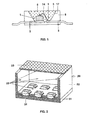
- FIG. 1 For example, for use in a white LED together with a GainN chip, a structure similar to that in FIG US Pat. No. 5,998,925 described used.
- the structure of such a white light source is shown in FIG FIG. 1 shown explicitly.
- the light source is a semiconductor device (chip 1) of the type InGaN having a peak emission wavelength of 420 nm and a half width of 25 nm with a first and second electrical connection 2.
- Chip 1 embedded in an opaque base housing 8 in the region of a recess 9 , One of the terminals 3 is connected to the chip 1 via a bonding wire 14.
- the recess has a wall 17, which serves as a reflector for the blue primary radiation of the chip 1.
- the recess 9 is filled with a potting compound 5, the main constituents of an epoxy casting resin (80 to 90 wt .-%) and phosphor pigments 6 (less as 15% by weight). Other minor proportions include methyl ether and Aerosil.
- the phosphor pigments are a mixture.
- the first conversion phosphor is selected from Table 1.
- the second phosphor is selected from Tab. 2 and the third from Tab. 3.
- a section of a surface light 20 is shown as a lighting unit. It consists of a common carrier 21, to which a cuboid outer housing 22 is glued. Its upper side is provided with a common cover 23.
- the cuboid housing has recesses in which individual semiconductor components 24 are housed. They are UV-emitting light-emitting diodes with a peak emission of 380 nm.
- the conversion into white light takes place by means of conversion layers, which sit directly in the casting resin of the individual LED, similar to FIG. 1 described or layers 25 which are mounted on all UV radiation accessible surfaces. These include the inner surfaces of the side walls of the housing, the cover and the bottom part.
- the conversion layers 25 consist of three phosphors which emit in the yellow, green and blue spectral range using at least one of the phosphors according to the invention from Tables 1 to 3.
- the ZnS phosphors for LEDs. They show a good processing behavior in the LED environment. These are mainly the blue-emitting phosphor ZnS: Ag, the green-emitting phosphor ZnS: Cu, Al and the red-emitting phosphor ZnS: Cu, Mn from Table 4. It should be emphasized that with these three phosphors one white emitting phosphor mixture can be realized, under excitation by an LED with primary radiation in the range 370 to 410 nm, see Example 6 in Fig. 6 , Since these three phosphors are chemically almost identical materials, they can be processed very well as a phosphor mixture in a casting resin or other resin or in a slurry. Tab.
- Tab. 6 finally shows 15 exemplary embodiments of specific combinations of phosphors from Tab. 4 in conjunction with a primary light source (UV LED) with an emission peak in the range from 370 to 420 nm.
- a primary light source UV LED
- the individual UV diodes are summarized in Tab. 5, in which the emission peak and the color locus (if defined, ie from 380 nm) of the individual diodes is indicated.
- the UV diode does not contribute to the secondary emission, also because of the strong absorption by the three phosphors.
- Embodiment # 15 uses a blue emitting diode with 420 nm peak emission with such high intensity that it can fully replace the blue phosphor and only requires two additional phosphors in the green and red.
- Tab. 5 No. em x y UV1 370 UV2 380 0.2 0.14 UV 3 390 0.19 0.09 UV4 400 0.18 0.05 UV5 410 0.18 0.03 UV6 420 0.17 0.02
Landscapes
- Chemical & Material Sciences (AREA)
- Inorganic Chemistry (AREA)
- Engineering & Computer Science (AREA)
- Materials Engineering (AREA)
- Organic Chemistry (AREA)
- Luminescent Compositions (AREA)
- Led Device Packages (AREA)
- Planar Illumination Modules (AREA)
- Electroluminescent Light Sources (AREA)
Abstract
Description
- Die Erfindung geht aus von einer Beleuchtungseinheit mit mindestens einer LED als Lichtquelle gemäß dem Oberbegriff des Anspruchs 1. Es handelt sich insbesondere um eine im Sichtbaren oder Weißen emittierenden Lumineszenz-Konversions-LED auf der Basis einer primär im nahen UV oder kurzwelligen Blau emittierenden LED.
- LEDs, die weißes Licht abgeben, werden derzeit vorwiegend durch die Kombination einer im Blauen bei etwa 460 nm emittierenden Ga(In)N-LED und eines gelb emittierenden YAG:Ce3+-Leuchtstoffs erzeugt (
US 5 998 925 undEP 862 794 WO 00/33389 WO 00/33390 - Grundsätzlich ist außerdem bekannt, weiß emittierende LEDs auch mit sogenannten organischen LEDs zu realisieren oder durch Zusammenschalten monochromer LEDs mit entsprechender Farbmischung. Meist wird eine UV LED (Emissionsmaximum zwischen 300 und 370 nm) verwendet, die mittels mehrerer Leuchtstoffe, meist drei, die im roten, grünen und blauen Spektralbereich emittieren (RGB-Mischung) in weißes Licht umgewandelt werden (
WO 98 39 805 WO 98 39 807 WO 97 48 138 - Für weiß emittierende Quellen von hoher Lichtqualität mit kleinen Dimensionen oder als Hintergrundbeleuchtung von z. B. LCDs sind Leuchtstofflampen und Glühlampen wenig geeignet OLEDs sind dazu zwar besser geeignet, allerdings ist die UV-Beständigkeit von organischen Leuchtstoffen im Vergleich zu anorganische Leuchtstoffen schlechter. Außerdem sind die Herstellkosten höher. Blaue LEDs mit dem Leuchtstoff YAG:Ce3+ (und davon abgeleiteten Granaten) sind prinzipiell ebenfalls geeignet, jedoch bestehen Nachteile in der Farborteinstellung: Nur in beschränkter Weise kann der Farbort derart gewählt werden, dass weißes Licht entsteht, das eine gute Farbwiedergabe ermöglicht, da der weiße Farbeindruck primär durch die Mischung blauer Emission der LED und gelber Emission des Leuchtstoffs entsteht. Der Nachteil von Leuchtstofflampen und UV-(O)LEDs besteht darin, dass UV-Energie in sichtbares Licht mit einer schlechten Energieeffizienz umgewandelt wird; UV-Strahlung (in Leuchtstofflampen 254 und 365 nm; in UV LEDs 300 - 370 nm) einer Wellenlänge von z. B. 254 nm wird umgewandelt in Licht mit einer Wellenlänge von 450-650 nm. Das bedeutet einen Energieverlust von 40 bis 60 % bei einer theoretischen Quanteneffizienz von 100%.
- Organische Leuchtstoffe sind im allgemeinen schwieriger herzustellen als anorganische Leuchtstoffe, und sind darüber hinaus im allgemeinen zu instabil, um in Lichtquellen hoher Lebensdauer (z. B. über 30.000 Stunden) eingesetzt werden zu können.
- Dieser Stand der Technik hat einige bedeutende Nachteile hinsichtlich der Energieeffizienz der Kombination aus LED und Leuchtstoffen und/oder der Stabilität der Leuchtstoffe und/oder Beschränkungen hinsichtlich der geometrischen Dimensionen.
- Es ist Aufgabe der vorliegenden Erfindung, eine Beleuchtungseinheit mit mindestens einer LED als Lichtquellegemäß dem Oberbegriff des Anspruchs 1 bereitzustellen, die sich durch hohe Effizienz auszeichnet.
- Diese Aufgaben werden durch die kennzeichnenden Merkmale des Anspruchs 1 gelöst. Besonders vorteilhafte Ausgestaltungen finden sich in den abhängigen Ansprüchen.
- Die Erfindung ist besonders vorteilhaft im Zusammenhang mit der Entwicklung einer im Sichtbaren bzw. Weißen emittierenden LED. Diese LED kann hergestellt werden durch Kombination einer im nahen UV oder sehr kurzwelligem blaues Licht (hier zusammenfassend als "kurzwellig" bezeichnet) emittierenden LED mit einer Emissionswellenlänge zwischen 370 und 430 nm und mindestens einem der unten angeführten Leuchtstoffe, der die Strahlung der LED ganz oder teilweise absorbiert und selbst in Spektralbereichen emittiert, deren additive Mischung mit dem Licht der LED und /oder anderen Farbstoffe weißes Licht mit guter Farbwiedergabe oder Licht mit einem gewünschten Farbort ergibt. Je nach Anwendung kann ein einziger Leuchtstoff mit den erfindungsgemäßen Eigenschaften ausreichen. Evtl. kann er auch mit einem oder mehreren anderen erfindungsgemäßen Leuchtstoffen oder Leuchtstoffen anderer Klassen, beispielsweise vom Typ YAG:Ce, kombiniert werden. Das blaue Licht der LED ist hier nicht (oder kaum) direkt nutzbar, im Gegensatz zum Stand der Technik, der längerwelliges Blau (430 bis 480 nm) verwendet, sondern eignet sich nur zur primären Anregung der Leuchtstoffe.
- Eine primäre Strahlungsquelle, deren Emission viel näher an der Wellenlänge liegt, bei der die Leuchtstoffe emittieren, kann die Energieeffizienz erheblich steigern. Bei einer Quelle, die bei 400 nm emittiert, reduziert sich zum Beispiel der Energie-Verlust schon auf nur noch 12 bis 39%.
- Das technische Problem liegt in der Entwicklung und Produktion ausreichend effizienter Leuchtstoffe, die im spektralen Bereich zwischen 370 nm und 430 nm anregbar sind und gleichzeitig ein passendes Emissionsverhalten zeigen.
- Um eine farbige oder weiße LED zu realisieren, wird ein erfindungsgemäßer Leuchtstoff, evtl. in Verbindung mit einem oder mehreren anderen Leuchtstoffen mit einem möglichst transparenten Bindemittel kombiniert (
EP 862 794 - Die Erfindung betrifft insbesondere eine Beleuchtungseinheit mit mindestens einer LED als Lichtquelle (light emitting diode), die besondere spezifisch gewünschte Farbtöne erzeugt (beispielsweise Magenta) oder die beispielsweise weißes Licht erzeugt, indem eine primär kurzwellig (also UV bis blau im Bereich 370 bis 430 nm) emittierende Strahlung mittels mehrerer Leuchtstoffe in Weiß konvertiert wird: entweder durch Mischung der sekundären Strahlung eines blau und gelb emittierenden Leuchtstoffs oder insbesondere durch RGB-Mischung aus drei Leuchtstoffen die rot, grün und blau emittieren. Für besonders hohe Anforderungen an die Farbwiedergabe können auch mehr als drei Leuchtstoffe kombiniert werden. Zu diesem Zweck kann auch einer der erfindungsgemäß eingesetzten Leuchtstoffe mit anderen, bereits für diese Verwendung bekannten Leuchtstoffen wie beispielsweise SrS:Eu (
WO 00/33390 US 5 998 925 ) kombiniert werden. - Als primär kurzwellig emittierende LED eignet sich insbesondere eine Ga(In,Al)N-LED, aber auch jeder andere Weg zur Erzeugung einer kurzwelligen LED mit einer primären Emission im Bereich 370 bis 430 nm.
- Die Erfindung erweitert die spektrale Emissionscharakteristik von LEDs indem über den gegenwärtige Kenntnisstand hinaus weitere Leuchtstoffe und deren Mischungen Anwendung finden (siehe Tab. 1 bis 3). Dabei kann die Auswahl der angewendeten Leuchtstoffe und Mischungen hiervon so getroffen werden, das neben farbechten Weiß auch andere Mischfarben mit breitbandiger Emission erzeugt werden. Generell wird das emittierte Licht der LED von der Mischung, die Leuchtstoffe enthält, absorbiert. Diese Mischung ist entweder direkt auf der LED aufgebracht oder in einem Harz oder Silikon dispergiert oder aufgebracht auf einer transparenten Scheibe über einer LED oder aufgebracht auf einer transparenten Scheibe über mehreren LEDs.
- Der erfinderische Schritt besteht darin, dass durch die Verwendung von LEDs mit Emissionswellenlängen zwischen 370 und 430 nm (unsichtbar oder kaum sichtbares tiefblau) und die Verwendung von Leuchtstoffen, die unten aufgelistet sind, eine verbesserte spektrale Anpassung der LED-Emission ermöglicht wird und beliebige Farborte einstellbar werden, und zwar mit einer höheren Energieeffizienz als mit den konventionellen LEDs.
- Anorganische Leuchtstoffe, die relativ langweilig anregbar sind, sind derzeit kaum bekannt. Überraschenderweise hat sich jedoch gezeigt, dass es eine Anzahl von anorganischen Leuchtstoffen gibt, die geeignet sind, um mit Strahlung einer Peak-Emissions-Wellenlänge von 370-430 nm noch effizient angeregt zu werden. Typische Halbwertsbreiten der Emission liegen bei 20 nm bis 50 nm. Die Absorption der Leuchtstoffe kann durch die gewählten Strukturparameter und chemische Zusammensetzung gesteuert werden. Solche Leuchtstoffe haben alle eine relativ kleine Bandlücke (typisch etwa 3 eV) oder sie haben ein starkes Kristallfeld für das Ion, welches das von der LED emittierte UV/Blau -Licht um 400 nm absorbiert.
- Abhängig von der gewählten Lumineszenzwellenlänge der LED (370-430 nm) und abhängig von der gewünschten Farbwiedergabe und /oder dem gewünschten Farbort können bestimmte Kombinationen von Leuchtstoffen in der Leuchtstoffmischung gewählt werden. Die am besten geeignete Leuchtstoffmischung ist somit vom gewählten Ziel (Farbwiedergabe, Farbort, Farbtemperatur) und der vorhandenen LED-Emissionswellenlänge abhängig.
- Jeder Leuchtstoff, der die oben erwähnten Bedingungen erfüllt, ist im Prinzip geeignet für die Anwendung. Leuchtstoffe, die effizient emittieren und im Gebiet von 370-430 nm effizient aru-egbar oder zumindest teilweise anregbar sind, sind in den folgenden Tabellen aufgeführt. Tab. 1 beschreibt geeignete blaue Leuchtstoffe mit einer Wellenlänge der Peakemission von 440 bis 485 nm, Tab. 2 geeignete grüne Leuchtstoffe mit einer Wellenlänge der Peakemission von 505 bis 550 nm und Tab. 3 geeignete rote Leuchtstoffe mit Wellenlänge der Peakemission von 560 bis 670 nm. Damit ist es erstmals möglich, LEDs mit hoher Effizienz herzustellen, die auf einer kurzwellig emittierenden Diode basieren, die mehrere Leuchtstoffe anregt.
Tabelle 1: Blau emittierende Leuchtstoffe: M5(PO4)3(X):Eu2+ mit M = zumindest eines der Metalle Ba, Ca allein oder in Kombination mit Sr (bevorzugt ist Anteil Sr höchstens 85%), wobei X = zumindest eines der Halogene F oder Cl; M*3MgSi2O8:Eu2+ mit M = zumindest eines der Metalle Ba, Ca, Sr allein oder in Kombination Ba5SiO4Br6:Eu2+ Ba1.29Al12O19.29:Eu2+ YSiO2N:Ce3+ (Sr,Ba)2Al6O31:Eu2+ MF2:Eu2+ mit M = zumindest eines der Metalle Ba, Sr, Ca; bevorzugt ist der Anteil des Ba an M > 5 %, beispielsweise Ba = 10 %, also M = Ba0.10Sr0.45Ca0.45. Ba0.57Eu0.09O0.34Al11.11O17:Eu2+ M**MgAl10O17:Eu2+ mit M** = zumindest eines der Metalle Eu, Sr allein oder in Kombination mit Ba (bevorzugt ist Anteil Ba höchstens 75%); MLn2S4:Ce3+ mit M = eine Kombination der Metalle Ca, Sr; und Ln = zumindest eines der Metalle La, Y, Gd. Tabelle 2: Grün (und Blaugrün) emittierende Leuchtstoffe SrAl2O4:Eu2+ MB03:(Ce3+,Tb3+) mit M = zumindest eines der Metalle Sc, Gd, Lu allein oder in Kombination mit Y (imsb. ist Y-Anteil < 40%); und als Aktivator fungieren die Metalle Ce und Tb gemeinsam; insbesondere liegt der Anteil des Ce am Metall M im Bereich 5 % ≤ Ce ≤ 20 % und der Anteil des Tb am Metall im Bereich 4 % ≤Tb ≤ 20; bevorzugt ist Anteil Ce > Anteil Tb; M2SiO5:(Ce3+,Tb3+) mit M = zumindest eines der Metalle Y, Gd, Lu; und als Aktivator fungieren die Metalle Ce und Tb gemeinsam (bevorzugt ist Anteil Ce> Anteil Tb); MN+2S4:Ak mit M = zumindest eines der Metalle Zn, Mg, Ca, Sr, Ba; mit N = zumindest eines der Metalle Al, Ga, In; und Ak = entweder eine Kombination von Eu2+, Mn2 zusammen (bevorzugt ist Anteil Eu > Anteil Mn) oder eine Kombination von Ce3+,Tb3+ zusammen (bevorzugt ist Anteil Ce > Anteil Tb); SrBaSiO4:Eu2+ Ba0.82Al12O18.82:Eu2+ Ba0.82Al12O18.82:Eu2+,Mn2+ Y5(SiO4)3N:Ce3+; Ca8Mg(SiO4)4Cl2:Ak2+ mit Ak = Eu2+ allein oder mit Mn2 zusammen (bevorzugt ist Anteil Eu > 2xAnteil Mn); Sr4Al14O25:Eu2+ (Ba,Sr)MgAl10O17:Ak mit Ak = Eu2+ entweder in Kombination mit Ce3+ und Tb3+, oder in Kombination mit Mn2+ ; bevorzugt ist Anteil Eu am Aktivator Ak > 50 %; Sr6BP5O20:Eu2+ Sr2P2O7:(Eu2+,Tb3+) mit Eu und Tb gemeinsam BaSi2O5:Eu2+ Tabelle 3: Rot (Orangerot bis Tiefrot) emittierende Leuchtstoffe Ln2O2St:Ak3+ wobei Ln = zumindest eines der Metalle Gd, La, Lu allein oder in Kombination mit Y (bevorzugt ist Anteil Y höchstens 40%; insbesondere ist Anteil La mindestens 10 %); und mit St = zumindest eines der Elemente S, Se, Te; und wobei Ak = Eu allein oder in Kombination mit Bi; Ln2WmO6:Ak3+ wobei Ln = zumindest eines der Metalle Y, Gd, La, Lu; und mit Wm = zumindest eines der Elemente W, Mo, Te; und wobei Ak = Eu allein oder in Kombination mit Bi; (Zn,Cd)S:Ag+ wobei Zn und Cd nur in Kombination verwendet werden; bevorzugt ist Anteil Zn < Anteil Cd; Mg28Ge7.5O38F10:Mn4+ Sr 2 P 2 O 7 :Eu2+,Mn2+ M3MgSi2O8:Eu2+,Mn2+ mit M = zumindest eines der Metalle Ca, Ba, Sr, (M1)2(M2)(BO3)2:Eu2+ mit M1 = zumindest eines der Metalle Ba, Sr; und mit M2 ist zumindest eines der Metalle Mg,Ca; bevorzugt ist der Anteil Ba am Kation M1 mindestens 80 %; bevorzugt ist der Anteil Mg am Metall M2 mindestens 70%. - Es wird angemerkt, dass der Aktivator im allgemeinen jeweils einen Anteil des führenden Kations (= Metall, insbesondere ein Lanthanid Ln) ersetzt, beispielsweise steht MS:Eu(5 %) für M1-0.05Eu0.05S.
- Die Formulierung "M = zumindest eines der Metalle X, Y;" bedeutet entweder das Metall X oder das Metall Y allein oder aber eine Kombination beider Metalle, also M = XaYb mit a+b = 1.
- Bei einer weißen LED wird ein Aufbau ähnlich wie im eingangs erwähnten Stand der Technik beschrieben verwendet. Als UV-Diode (primäre Strahlungsquelle) wird bevorzugt GaInN oder GaN oder GaInAlN verwendet. Beispielsweise hat sie eine Peakwellenlänge von 400 nm und eine Halbwertsbreite von 20 nm. Das Diodensubstrat wird mit einer Suspension aus drei Leuchtstoffen, je einer mit einem Emissionsmaximum im Roten, Grünen und Blauen Spektralbereich direkt oder indirekt beschichtet. Von diesen Leuchtstoffen ist zumindest einer ausgewählt aus den Tabellen 1 bis 3, und kombiniert entweder mit bekannten Leuchtstoffen oder mit Leuchtstoffen aus den anderen Tabellen. Die Leuchtstoffmischung wird bei etwa 200 °C eingebrannt. Damit wird eine Farbwiedergabe von typisch 80 erzielt.
- Im folgenden soll die Erfindung anhand mehrerer Ausführungsbeispiele näher erläutert werden. Es zeigen:
- Figur 1
- ein Halbleiterbauelement, das als Lichtquelle (LED) für weißes Licht dient;
- Figur 2
- eine Beleuchtungseinheit mit Leuchtstoffen gemäß der vorliegenden Erfindung;
- Figur 3 bis 17
- das Emissionsspektrum von LEDs mit verschiedenen Leuchtstoffmischungen gemäß der vorliegenden Erfindung.
- Für den Einsatz in einer weißen LED zusammen mit einem GainN-Chip wird beispielsweise ein Aufbau ähnlich wie in
US 5 998 925 beschrieben verwendet. Der Aufbau einer derartigen Lichtquelle für weißes Licht ist inFigur 1 explizit gezeigt. Die Lichtquelle ist ein Halbleiterbauelement (Chip 1) des Typs lnGaN mit einer Peak-Emissionswellenlänge von 420 nm und einer Halbwertsbreite von 25 nm mit einem ersten und zweiten elektrischen Anschluss 2,3, das in ein lichtundurchlässiges Grundgehäuse 8 im Bereich einer Ausnehmung 9 eingebettet ist. Einer der Anschlüsse 3 ist über einen Bonddraht 14 mit dem Chip 1 verbunden. Die Ausnehmung hat eine Wand 17, die als Reflektor für die blaue Primärstrahlung des Chips 1 dient. Die Ausnehmung 9 ist mit einer Vergussmasse 5 gefüllt, die als Hauptbestandteile ein Epoxidgießharz (80 bis 90 Gew.-%) und Leuchtstoffpigmente 6 (weniger als 15 Gew.-%) enthält. Weitere geringe Anteile entfallen u.a. auf Methylether und Aerosil. Die Leuchtstoffpigmente sind eine Mischung. Der erste Konversions-Leuchtstoff ist aus Tab. 1 ausgewählt. Der zweite Leuchtstoff ist aus Tab. 2 und der dritte aus Tab. 3 ausgewählt. - In
Figur 2 ist ein Ausschnitt aus einer Flächenleuchte 20 als Beleuchtungseinheit gezeigt. Sie besteht aus einem gemeinsamen Träger 21, auf den ein quaderförmiges äußeres Gehäuse 22 aufgeklebt ist. Seine Oberseite ist mit einer gemeinsamen Abdeckung 23 versehen. Das quaderförmige Gehäuse besitzt Aussparungen, in denen einzelne Halbleiter-Bauelemente 24 untergebracht sind. Sie sind UVemittierende Leuchtdioden mit einer Peakemission von 380 nm. Die Umwandlung in weißes Licht erfolgt mittels Konversionsschichten, die direkt im Gießharz der einzelnen LED sitzen ähnlich wie inFigur 1 beschrieben oder Schichten 25, die auf allen der UV-Strahlung zugänglichen Flächen angebracht sind. Dazu zählen die innen liegenden Oberflächen der Seitenwände des Gehäuses, der Abdeckung und des Bodenteils, Die Konversionsschichten 25 bestehen aus drei Leuchtstoffen, die im gelben, grünen und blauen Spektralbereich emittieren unter Benutzung zumindest einen der erfindungsgemäßen Leuchtstoffe aus Tab. 1 bis 3. - Einige konkrete Ausführungsbeispiele von in Kombination untersuchten Leuchtstoffen sind in Tab. 4 zusammengefasst. Es handelt sich um eine Zusammenfassung geeigneter erfindungsgemäßer und an sich bekannter Leuchtstoffe in allen drei Spektralbereichen. In Sp. 1 ist die Versuchsnummer angegeben, in Sp. 2 die chemische Formel des Leuchtstoffs, in Sp. 3 das Emissionsmaximum des Leuchtstoffs, in Sp. 4 und 5 die x- und y- Farbortkoordinaten. In Sp. 6 und 7 sind die Reflektivität und die Quanteneffizienz (jeweils in Prozent) angegeben.
- Besonders bevorzugt ist auch die Anwendung der ZnS-Leuchtstoffe für LEDs. Sie zeigen ein gutes Verarbeitungsverhalten in der LED-Umgebung. Es handelt sich dabei vor allem um den blau emittierenden Leuchtstoff ZnS:Ag, den grün emittierenden Leuchtstoff ZnS:Cu,Al und den rot emittierenden Leuchtstoff ZnS:Cu,Mn aus Tab. 4. Besonders hervorzuheben ist, dass sich mit diesen drei Leuchtstoffen eine weiß emittierende Leuchtstoff-Mischung realisieren lässt, unter Anregung durch eine LED mit Primärstrahlung im Bereich 370 bis 410 nm, siehe Ausführungsbeispiel 6 in
Fig. 6 . Da diese drei Leuchtstoffe chemisch nahezu identische Materialien sind, lassen sie sich sehr gut als Leuchtstoffmischung in einem Gießharz oder anderem Harz oder bei einer Beschlämmung verarbeiten.Tab. 4 Nr. Formel Em x y R (%) Q.E (%) 1 Ba3MgSi2O8: Eu (5%) 440 0,16 0,07 42 50 2 (Ba0.15Sr0.85)5(PO4)3Cl:Eu2+ 448 0,15 0,05 46 76 3 ZnS :Ag 452 0,14 0,07 76 63 4 (Ba,Sr)MgAl10O17:Eu2+ 454 0,15 0,08 49 83 5 SrMgAl10O17:Eu2+ 467 0,15 0,19 63 92 6 EuMgAl10O17 481 0,17 0,31 35 63 7 ZnS:Cu 506 0,19 0,43 22 48 8 Ba0.74Eu0.08Al12O18.82 507 0,22 0,43 52 87 9 Ca6Mg(SiO4)4Cl2:Eu2+ 508 0,17 0,6 34 67 10ZnS:Cu 510 0,2 0,46 16 55 11 BaMgAl10O17:Eu2+,Mn2+ 513 0,14 0,21 64 95 12 Ba0.72Eu0.05Mn0.05Al12O18.82 514 0,21 0,46 71 97 13 BaMgAl10O17:Eu2+,Mn2+ 515 0,14 0,65 39 88 14 (Sr,Ba)SiO4:Eu2+ 517 0,23 0,61 54 15 SrAl2O4:Eu2+ 523 0,29 0,58 28 77 16 ZnS:Cu,Al 534 0,31 0,61 29 83 17 YBO3:(Ce3+,Tb3+) (9.5%/5%) 545 0,34 0,59 80 69 18 Ca8Mg(SiO4)4Cl2:Eu2+, Mn2+ 550 0,38 0,57 30 61 19 Sr1.95Ba0.03Eu0.02SiO4 563 0,44 0,53 21 20 Sr2P2O7:Eu2+ , Mn2+ 570 0,32 0,27 63 46 21 ZnS :Cu.Mn 585 0,49 0,45 19 44 22 Gd2MoO6:Eu3+ (20%) 610 0,66 0,34 50 23 Y2W0.98Mo0.02O6:Eu3+ 612 0,61 0,38 68 73 24 Y2WO6:Eu3+, Bi3+ (7.5%, 0.5%) 612 0,64 0,36 52 25 Lu2WO6:Eu3+, Bi3+ (7.6%, 1%) 612 0,64 0,36 65 26 SrS:Eu2+ (2%) 616 0,63 0,37 52 91 27 La2TeO6:Eu3+ (%) 617 0,66 0,34 76 28 (La,Y)2O2S:Eu3+ (..) 626 0,67 0,33 84 73 29 Sr2Si5Na8:Eu2+ (10%) 636 0,64 0,36 12 70 30 (Ba,Ca,Sr)MgSi2O6: Eu,Mn 657 0,39 0,16 47 52 - Der Leuchtstoff Nr. 14 (Sr,Ba)SiO4:Eu2+ ist im Grünen so breitbandig, dass hier auf eine separate Rotkomponente verzichtet werden.
- In Tab. 6 sind schließlich 15 Ausführungsbeispiele konkreter Kombinationen von Leuchtstoffen aus Tab. 4 in Verbindung mit einer primären Lichtquelle (UV-LED) mit einem Emissionspeak im Bereich 370 bis 420 nm gezeigt. Die einzelnen UV-Dioden sind in Tab. 5 zusammengefasst, in der der Emissionspeak und der Farbort (soweit definiert, also ab 380 nm) der einzelnen Dioden angegeben ist.
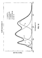
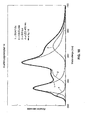
- In Sp. 1 bis 4 der Tab. 6 sind die Angaben aus Tab. 4 nochmals eingefügt zum besseren Abgleich. In Sp. 5 bis 10 ist die Brauchbarkeit der einzelnen Leuchtstoffe für Anregung bei verschiedenen Wellenlängen festgehalten und zwar systematisch für die kurzwelligen Dioden mit Emissionspeak bei 370 bis 420 nm in Schritten von 10 nm. Die anschließenden 15 Spalten zeigen konkrete Beispiele (als Ex 1 bis Ex 15 bezeichnet) einer RGB-Mischung, also die Kombination der kurzwelligen LED (die zweite Zeile gibt die gewählte Peakemission an) mit drei Leuchtstoffen aus dem roten, grünen und blauen Spektralbereich. Die in der jeweiligen Spalte angegebene Zahl bezeichnet den relativen Anteil an der spektralen Emission.
- Bei einer stark kurzwelligen UV-Diode, unter 380 nm, liefert die UV-Diode keinerlei Anteil an der sekundären Emission, auch wegen der starken Absorption durch die drei Leuchtstoffe.
- Ab einer primären Emission von 380 nm liefert die Diode jedoch einen kleinen, mit steigender Wellenlänge steigenden Anteil im Blauen zusätzlich zum blauen Leuchtstoff. Dieser Anteil erscheint in der Tab. 5 als zusätzlicher vierter Beitrag.
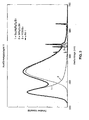
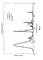
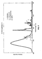
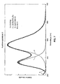
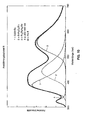
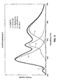
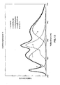
- Schließlich sind in den letzten beiden Zeilen der Tab. 6 die gemessenen Farbortkoordinaten des Gesamtsystems eingetragen, die einen weiten Bereich von Weißtönen in der Farbtafel abdecken. Die spektrale Verteilung dieser System ist in den
Figuren 3 (entsprechend Ex 1) bis 17 (entsprechend Ex 15) dargestellt. - Als besonders geeignete Leuchtstoffe für die Anwendung in Dreifarbenmischungen unter Primärbestrahlung bei 370 bis 420 nm haben sich dabei die blau emittierenden Leuchtstoffe Nr. 2, 4 und 6, die grün emittierenden Leuchtstoffe 8, 9, 10, 13, 15, 16, 17 und 18 sowie die rot emittierenden Leuchtstoffe 26, 28 und 29 erwiesen.
- Das Ausführungsbeispiel Nr. 15 verwendet eine blau emittierende Diode mit 420 nm Peakemission mit so hoher Intensität, dass sie den blauen Leuchtstoff voll ersetzen kann und nur zwei zusätzliche Leuchtstoffe im Grünen und Roten benötigt.
Tab. 5 Nr. Em x y UV1 370 UV2 380 0,2 0,14 UV3 390 0,19 0,09 UV4 400 0,18 0,05 UV5 410 0,18 0,03 UV6 420 0,17 0,02 
Claims (7)
- Beleuchtungseinheit mit mindestens einer LED als Lichtquelle, wobei die LED Primärstrahlung im Bereich von 370 bis 430 nm des optischen Spektrums (Peakwellenlänge) emittiert, wobei diese Strahlung teilweise oder vollständig in längerwellige Strahlung durch mindestens einen Leuchtstoff konvertiert wird, so dass weißes Licht erzeugt wird, dadurch gekennzeichnet, dass der Leuchtstoff (Sr,Ba)2SiO4:Eu2+ ist.
- Beleuchtungseinheit nach Anspruch 1, dadurch gekennzeichnet, dass der Leuchtstoff SrBaSiO4:Eu2+ ist.
- Beleuchtungseinheit nach Anspruch 1 oder 2, dadurch gekennzeichnet, dass die primäre Strahlung durch zumindest einen zweiten Leuchtstoff zusammen mit dem ersten Leuchtstoff konvertiert wird, wobei der zweite Leuchtstoff im blauen, grünen oder roten Spektralbereich emittiert, so dass weißes Licht erzeugt wird, wobei im Fall, dass der Leuchtstoff blaues Licht emittiert, dessen Maximum der Wellenlänge zwischen 440 und 485 nm liegt, und wobei im Fall, dass der Leuchtstoff grünes Licht emittiert, dessen Maximum der Wellenlänge zwischen 505 und 550 nm liegt, und wobei im Fall, dass der Leuchtstoff rotes Licht emittiert, dessen Maximum der Wellenlänge im Bereich 560 bis 670 nm liegt.
- Beleuchtungseinheit mit mindestens einer LED als Lichtquelle, wobei die LED eine Lumineszenzkonversions-LED ist, die im sichtbaren Spektralbereich oder die weiß emittiert, wobei die LED primär im nahen UV oder blauen Spektralbereich bei kurzen Wellenlängen emittiert, dadurch gekennzeichnet, dass der Leuchtstoff (Sr,Ba)2SiO4:Eu2+ für die Sekundäremission benutzt wird.
- Beleuchtungseinheit nach Anspruch 4, dadurch gekennzeichnet, dass dieser Leuchtstoff im grünen Spektralbereich emittiert und dass ein blauer Leuchtstoff zusätzlich benutzt wird um weißes Licht zu erzeugen.
- Beleuchtungseinheit nach Anspruch 5, dadurch gekennzeichnet, dass zusätzlich ein Leuchtstoff, der rot emittiert, benutzt wird.
- Beleuchtungseinheit nach Anspruch 4, dadurch gekennzeichnet, dass die LED primäre Strahlung im Bereich von 370 bis 430 nm des optischen Spektralbereichs (Peakwellenlänge) emittiert.
Applications Claiming Priority (2)
| Application Number | Priority Date | Filing Date | Title |
|---|---|---|---|
| DE10036940A DE10036940A1 (de) | 2000-07-28 | 2000-07-28 | Lumineszenz-Konversions-LED |
| EP01956394A EP1305833A1 (de) | 2000-07-28 | 2001-07-27 | Beleuchtungseinheit mit mindestens einer led als lichtquelle |
Related Parent Applications (1)
| Application Number | Title | Priority Date | Filing Date |
|---|---|---|---|
| EP01956394A Division EP1305833A1 (de) | 2000-07-28 | 2001-07-27 | Beleuchtungseinheit mit mindestens einer led als lichtquelle |
Publications (3)
| Publication Number | Publication Date |
|---|---|
| EP1970970A2 true EP1970970A2 (de) | 2008-09-17 |
| EP1970970A3 EP1970970A3 (de) | 2008-10-01 |
| EP1970970B1 EP1970970B1 (de) | 2016-12-07 |
Family
ID=7650618
Family Applications (2)
| Application Number | Title | Priority Date | Filing Date |
|---|---|---|---|
| EP08158704.0A Expired - Lifetime EP1970970B1 (de) | 2000-07-28 | 2001-07-27 | Beleuchtungseinheit mit mindestens einer LED als Lichtquelle |
| EP01956394A Ceased EP1305833A1 (de) | 2000-07-28 | 2001-07-27 | Beleuchtungseinheit mit mindestens einer led als lichtquelle |
Family Applications After (1)
| Application Number | Title | Priority Date | Filing Date |
|---|---|---|---|
| EP01956394A Ceased EP1305833A1 (de) | 2000-07-28 | 2001-07-27 | Beleuchtungseinheit mit mindestens einer led als lichtquelle |
Country Status (8)
| Country | Link |
|---|---|
| US (3) | US7064480B2 (de) |
| EP (2) | EP1970970B1 (de) |
| JP (2) | JP5419315B2 (de) |
| KR (1) | KR100920533B1 (de) |
| CN (1) | CN1214471C (de) |
| DE (1) | DE10036940A1 (de) |
| TW (1) | TW531904B (de) |
| WO (1) | WO2002011214A1 (de) |
Cited By (1)
| Publication number | Priority date | Publication date | Assignee | Title |
|---|---|---|---|---|
| WO2018162375A2 (de) | 2017-03-08 | 2018-09-13 | Merck Patent Gmbh | Leuchtstoffmischungen zur anwendung in dynamischen beleuchtungssystemen |
Families Citing this family (196)
| Publication number | Priority date | Publication date | Assignee | Title |
|---|---|---|---|---|
| BRPI9715293B1 (pt) | 1996-06-26 | 2016-11-01 | Osram Ag | elemento de cobertura para um elemento de construção optoeletrônico |
| US6680569B2 (en) * | 1999-02-18 | 2004-01-20 | Lumileds Lighting U.S. Llc | Red-deficiency compensating phosphor light emitting device |
| AT410266B (de) * | 2000-12-28 | 2003-03-25 | Tridonic Optoelectronics Gmbh | Lichtquelle mit einem lichtemittierenden element |
| JP4125878B2 (ja) * | 2001-08-27 | 2008-07-30 | 東芝電子エンジニアリング株式会社 | 発光装置 |
| KR20080087049A (ko) | 2001-09-03 | 2008-09-29 | 마츠시타 덴끼 산교 가부시키가이샤 | 형광체 층, 반도체발광장치, 반도체발광소자의 제조방법 |
| FR2830529B1 (fr) * | 2001-10-10 | 2004-10-08 | Rhodia Elect & Catalysis | Nouveaux tungstates de terres rares, leur procede de preparation et leur utilisation comme agent de protection contre les rayons ultraviolets |
| JP4168776B2 (ja) * | 2002-02-15 | 2008-10-22 | 三菱化学株式会社 | 発光装置及びそれを用いた照明装置 |
| EP1942531B1 (de) * | 2002-02-15 | 2010-05-19 | Mitsubishi Chemical Corporation | Lichtemittierendes Element und zughörige Beleuchtungsvorrichtung |
| JP3702863B2 (ja) * | 2002-05-15 | 2005-10-05 | 住友電気工業株式会社 | 白色発光素子 |
| US6809471B2 (en) * | 2002-06-28 | 2004-10-26 | General Electric Company | Phosphors containing oxides of alkaline-earth and Group-IIIB metals and light sources incorporating the same |
| JP3997124B2 (ja) * | 2002-08-26 | 2007-10-24 | 株式会社リコー | 画像読取装置の照明装置 |
| US7800121B2 (en) | 2002-08-30 | 2010-09-21 | Lumination Llc | Light emitting diode component |
| US7224000B2 (en) | 2002-08-30 | 2007-05-29 | Lumination, Llc | Light emitting diode component |
| FR2846663B1 (fr) * | 2002-11-05 | 2006-08-11 | Rhodia Elect & Catalysis | Materiau transformant la lumiere, notamment pour parois de serres, comprenant comme additif un silicate de baryum et de magnesium |
| DE10259946A1 (de) * | 2002-12-20 | 2004-07-15 | Tews, Walter, Dipl.-Chem. Dr.rer.nat.habil. | Leuchtstoffe zur Konversion der ultravioletten oder blauen Emission eines lichtemittierenden Elementes in sichtbare weiße Strahlung mit sehr hoher Farbwiedergabe |
| DE10260692B4 (de) * | 2002-12-23 | 2009-05-20 | Continental Automotive Gmbh | Flüssigkristallanzeige |
| KR100499079B1 (ko) * | 2003-02-10 | 2005-07-01 | 엘지전자 주식회사 | 녹색 산화물 형광체 |
| JP2004296830A (ja) * | 2003-03-27 | 2004-10-21 | Solidlite Corp | 白色ledの製造方法 |
| US20040227199A1 (en) * | 2003-05-15 | 2004-11-18 | Toshiba Kikai Kabushiki Kaisha | Minute flow passage and micro-chemical chip including the same |
| DE10326755A1 (de) * | 2003-06-13 | 2006-01-26 | Patent-Treuhand-Gesellschaft für elektrische Glühlampen mbH | Entladungslampe mit Zweibanden-Leuchtstoff |
| JP5456233B2 (ja) * | 2003-06-24 | 2014-03-26 | ジーイー ライティング ソリューションズ エルエルシー | Ledチップによる白色光発生のためのフルスペクトル蛍光体混合物 |
| US7462983B2 (en) * | 2003-06-27 | 2008-12-09 | Avago Technologies Ecbu Ip (Singapore) Pte. Ltd. | White light emitting device |
| US7075225B2 (en) | 2003-06-27 | 2006-07-11 | Tajul Arosh Baroky | White light emitting device |
| US7604378B2 (en) | 2003-07-02 | 2009-10-20 | S.C. Johnson & Son, Inc. | Color changing outdoor lights with active ingredient and sound emission |
| US7520635B2 (en) * | 2003-07-02 | 2009-04-21 | S.C. Johnson & Son, Inc. | Structures for color changing light devices |
| US7484860B2 (en) * | 2003-07-02 | 2009-02-03 | S.C. Johnson & Son, Inc. | Combination white light and colored LED light device with active ingredient emission |
| US7318659B2 (en) | 2004-03-03 | 2008-01-15 | S. C. Johnson & Son, Inc. | Combination white light and colored LED light device with active ingredient emission |
| US7476002B2 (en) | 2003-07-02 | 2009-01-13 | S.C. Johnson & Son, Inc. | Color changing light devices with active ingredient and sound emission for mood enhancement |
| US6987353B2 (en) * | 2003-08-02 | 2006-01-17 | Phosphortech Corporation | Light emitting device having sulfoselenide fluorescent phosphor |
| US7026755B2 (en) * | 2003-08-07 | 2006-04-11 | General Electric Company | Deep red phosphor for general illumination applications |
| US7675075B2 (en) | 2003-08-28 | 2010-03-09 | Panasonic Corporation | Semiconductor light emitting device, light emitting module, lighting apparatus, display element and manufacturing method of semiconductor light emitting device |
| JP4378242B2 (ja) * | 2003-09-25 | 2009-12-02 | 株式会社小糸製作所 | 車両用灯具 |
| US7488432B2 (en) * | 2003-10-28 | 2009-02-10 | Nichia Corporation | Fluorescent material and light-emitting device |
| JP4568894B2 (ja) | 2003-11-28 | 2010-10-27 | Dowaエレクトロニクス株式会社 | 複合導体および超電導機器システム |
| WO2005068584A1 (ja) * | 2004-01-16 | 2005-07-28 | Mitsubishi Chemical Corporation | 蛍光体、及びそれを用いた発光装置、照明装置ならびに画像表示装置 |
| JP4617889B2 (ja) * | 2004-01-16 | 2011-01-26 | 三菱化学株式会社 | 蛍光体、及びそれを用いた発光装置、照明装置、ならびに画像表示装置 |
| JP4617890B2 (ja) * | 2004-01-16 | 2011-01-26 | 三菱化学株式会社 | 蛍光体、及びそれを用いた発光装置、照明装置、ならびに画像表示装置 |
| US20070018573A1 (en) * | 2004-02-18 | 2007-01-25 | Showa Denko K,K. | Phosphor, production method thereof and light-emitting device using the phosphor |
| JP4511849B2 (ja) | 2004-02-27 | 2010-07-28 | Dowaエレクトロニクス株式会社 | 蛍光体およびその製造方法、光源、並びにled |
| JP2005286312A (ja) * | 2004-03-02 | 2005-10-13 | Fujikura Ltd | 発光デバイス及び照明装置 |
| US7503675B2 (en) | 2004-03-03 | 2009-03-17 | S.C. Johnson & Son, Inc. | Combination light device with insect control ingredient emission |
| KR20070007303A (ko) | 2004-03-03 | 2007-01-15 | 에스.씨. 존슨 앤드 선, 인코포레이티드 | 활성성분을 방출하는 발광다이오드 전구 |
| US7573072B2 (en) * | 2004-03-10 | 2009-08-11 | Lumination Llc | Phosphor and blends thereof for use in LEDs |
| FR2869159B1 (fr) * | 2004-04-16 | 2006-06-16 | Rhodia Chimie Sa | Diode electroluminescente emettant une lumiere blanche |
| KR100887489B1 (ko) * | 2004-04-27 | 2009-03-10 | 파나소닉 주식회사 | 형광체 조성물과 그 제조 방법, 및 그 형광체 조성물을이용한 발광 장치 |
| KR100655894B1 (ko) | 2004-05-06 | 2006-12-08 | 서울옵토디바이스주식회사 | 색온도 및 연색성이 우수한 파장변환 발광장치 |
| KR100658700B1 (ko) | 2004-05-13 | 2006-12-15 | 서울옵토디바이스주식회사 | Rgb 발광소자와 형광체를 조합한 발광장치 |
| JP4524468B2 (ja) | 2004-05-14 | 2010-08-18 | Dowaエレクトロニクス株式会社 | 蛍光体とその製造方法および当該蛍光体を用いた光源並びにled |
| CN100411200C (zh) * | 2004-05-18 | 2008-08-13 | 光宝科技股份有限公司 | 白光发光装置 |
| JP4491585B2 (ja) | 2004-05-28 | 2010-06-30 | Dowaエレクトロニクス株式会社 | 金属ペーストの製造方法 |
| US8308980B2 (en) | 2004-06-10 | 2012-11-13 | Seoul Semiconductor Co., Ltd. | Light emitting device |
| KR100665298B1 (ko) | 2004-06-10 | 2007-01-04 | 서울반도체 주식회사 | 발광장치 |
| KR100665299B1 (ko) | 2004-06-10 | 2007-01-04 | 서울반도체 주식회사 | 발광물질 |
| JP4414821B2 (ja) * | 2004-06-25 | 2010-02-10 | Dowaエレクトロニクス株式会社 | 蛍光体並びに光源およびled |
| JP2008506011A (ja) * | 2004-07-06 | 2008-02-28 | サーノフ コーポレーション | 効率的な緑色発光蛍光体、及び赤色発光蛍光体との組合せ |
| JP4511885B2 (ja) | 2004-07-09 | 2010-07-28 | Dowaエレクトロニクス株式会社 | 蛍光体及びled並びに光源 |
| JP4546176B2 (ja) * | 2004-07-16 | 2010-09-15 | 京セラ株式会社 | 発光装置 |
| US7476337B2 (en) | 2004-07-28 | 2009-01-13 | Dowa Electronics Materials Co., Ltd. | Phosphor and manufacturing method for the same, and light source |
| JP4933739B2 (ja) | 2004-08-02 | 2012-05-16 | Dowaホールディングス株式会社 | 電子線励起用の蛍光体および蛍光体膜、並びにそれらを用いたカラー表示装置 |
| US7138756B2 (en) | 2004-08-02 | 2006-11-21 | Dowa Mining Co., Ltd. | Phosphor for electron beam excitation and color display device using the same |
| US7575697B2 (en) * | 2004-08-04 | 2009-08-18 | Intematix Corporation | Silicate-based green phosphors |
| US20060049414A1 (en) * | 2004-08-19 | 2006-03-09 | Chandran Ramachandran G | Novel oxynitride phosphors |
| JP4524470B2 (ja) | 2004-08-20 | 2010-08-18 | Dowaエレクトロニクス株式会社 | 蛍光体およびその製造方法、並びに当該蛍光体を用いた光源 |
| US7476338B2 (en) | 2004-08-27 | 2009-01-13 | Dowa Electronics Materials Co., Ltd. | Phosphor and manufacturing method for the same, and light source |
| JP4543250B2 (ja) | 2004-08-27 | 2010-09-15 | Dowaエレクトロニクス株式会社 | 蛍光体混合物および発光装置 |
| JP4674348B2 (ja) * | 2004-09-22 | 2011-04-20 | 独立行政法人物質・材料研究機構 | 蛍光体とその製造方法および発光器具 |
| TWI256149B (en) * | 2004-09-27 | 2006-06-01 | Advanced Optoelectronic Tech | Light apparatus having adjustable color light and manufacturing method thereof |
| DE102004060358A1 (de) * | 2004-09-30 | 2006-04-13 | Osram Opto Semiconductors Gmbh | Verfahren zum Herstellen von Lumineszenzdiodenchips und Lumineszenzdiodenchip |
| JP4543253B2 (ja) | 2004-10-28 | 2010-09-15 | Dowaエレクトロニクス株式会社 | 蛍光体混合物および発光装置 |
| US7745814B2 (en) * | 2004-12-09 | 2010-06-29 | 3M Innovative Properties Company | Polychromatic LED's and related semiconductor devices |
| US7719015B2 (en) * | 2004-12-09 | 2010-05-18 | 3M Innovative Properties Company | Type II broadband or polychromatic LED's |
| US7402831B2 (en) * | 2004-12-09 | 2008-07-22 | 3M Innovative Properties Company | Adapting short-wavelength LED's for polychromatic, broadband, or “white” emission |
| US7648649B2 (en) * | 2005-02-02 | 2010-01-19 | Lumination Llc | Red line emitting phosphors for use in led applications |
| JP4892193B2 (ja) | 2005-03-01 | 2012-03-07 | Dowaホールディングス株式会社 | 蛍光体混合物および発光装置 |
| US7439668B2 (en) * | 2005-03-01 | 2008-10-21 | Lumination Llc | Oxynitride phosphors for use in lighting applications having improved color quality |
| US7524437B2 (en) | 2005-03-04 | 2009-04-28 | Dowa Electronics Materials Co., Ltd. | Phosphor and manufacturing method of the same, and light emitting device using the phosphor |
| US7276183B2 (en) * | 2005-03-25 | 2007-10-02 | Sarnoff Corporation | Metal silicate-silica-based polymorphous phosphors and lighting devices |
| US7445730B2 (en) | 2005-03-31 | 2008-11-04 | Dowa Electronics Materials Co., Ltd. | Phosphor and manufacturing method of the same, and light emitting device using the phosphor |
| US7443094B2 (en) | 2005-03-31 | 2008-10-28 | Dowa Electronics Materials Co., Ltd. | Phosphor and manufacturing method of the same, and light emitting device using the phosphor |
| JP4905627B2 (ja) * | 2005-04-25 | 2012-03-28 | 株式会社東芝 | 緑色蛍光体、白色ledおよびそれを用いたバックライト並びに液晶表示装置 |
| DE102005019376A1 (de) | 2005-04-26 | 2006-11-02 | Patent-Treuhand-Gesellschaft für elektrische Glühlampen mbH | Lumineszenzkonversions-LED |
| JP5057692B2 (ja) * | 2005-04-27 | 2012-10-24 | サムソン エルイーディー カンパニーリミテッド. | 発光ダイオードを利用したバックライトユニット |
| KR100780186B1 (ko) * | 2005-04-27 | 2007-11-27 | 삼성전기주식회사 | 발광다이오드를 이용한 lcd 백라이트 유니트 |
| JP4975269B2 (ja) | 2005-04-28 | 2012-07-11 | Dowaホールディングス株式会社 | 蛍光体およびその製造方法、並びに当該蛍光体を用いた発光装置 |
| DE102005031336B4 (de) | 2005-05-13 | 2008-01-31 | Osram Opto Semiconductors Gmbh | Projektionseinrichtung |
| JP2007049114A (ja) | 2005-05-30 | 2007-02-22 | Sharp Corp | 発光装置とその製造方法 |
| JP4794235B2 (ja) * | 2005-08-02 | 2011-10-19 | シャープ株式会社 | 発光装置 |
| DE102005040558A1 (de) | 2005-08-26 | 2007-03-01 | Osram Opto Semiconductors Gmbh | Verfahren zum Herstellen eines Lumineszenzdiodenchips und Lumineszenzdiodenchip |
| US7501753B2 (en) * | 2005-08-31 | 2009-03-10 | Lumination Llc | Phosphor and blends thereof for use in LEDs |
| US20070052342A1 (en) * | 2005-09-01 | 2007-03-08 | Sharp Kabushiki Kaisha | Light-emitting device |
| US7935975B2 (en) | 2005-09-29 | 2011-05-03 | Kabushiki Kaisha Toshiba | White LED lamp and backlight using the same, and liquid crystal display device using the backlight |
| JP4965840B2 (ja) * | 2005-09-29 | 2012-07-04 | 株式会社東芝 | 白色発光型ledランプの製造方法およびそれを用いたバックライトの製造方法並びに液晶表示装置の製造方法 |
| DE102006004397A1 (de) | 2005-09-30 | 2007-04-05 | Osram Opto Semiconductors Gmbh | Elektromagnetische Strahlung emittierendes optoelektronisches Bauelement und Verfahren zur Herstellung eines optoelektronischen Bauelements |
| DE102005059524A1 (de) | 2005-09-30 | 2007-04-05 | Osram Opto Semiconductors Gmbh | Gehäuse für ein elektromagnetische Strahlung emittierendes optoelektronisches Bauelement, Bauelement und Verfahren zum Herstellen eines Gehäuses oder eines Bauelements |
| DE102005052356A1 (de) | 2005-09-30 | 2007-04-12 | Osram Opto Semiconductors Gmbh | Beleuchtungseinheit mit Lumineszenzdiodenchip und Lichtleiter, Verfahren zum Herstellen einer Beleuchtungseinheit und LCD-Display |
| US20070125984A1 (en) * | 2005-12-01 | 2007-06-07 | Sarnoff Corporation | Phosphors protected against moisture and LED lighting devices |
| US8906262B2 (en) * | 2005-12-02 | 2014-12-09 | Lightscape Materials, Inc. | Metal silicate halide phosphors and LED lighting devices using the same |
| KR101055772B1 (ko) | 2005-12-15 | 2011-08-11 | 서울반도체 주식회사 | 발광장치 |
| WO2007081719A2 (en) | 2006-01-05 | 2007-07-19 | Illumitex, Inc. | Separate optical device for directing light from an led |
| JP2007231250A (ja) * | 2006-02-02 | 2007-09-13 | Nichia Chem Ind Ltd | 蛍光体及びそれを用いた発光装置 |
| CN101379164B (zh) * | 2006-02-10 | 2012-11-21 | 三菱化学株式会社 | 荧光体及其制造方法、含荧光体的组合物、发光装置、图像显示装置和照明装置 |
| JP5032043B2 (ja) | 2006-03-27 | 2012-09-26 | 豊田合成株式会社 | フェラスメタルアルカリ土類金属ケイ酸塩混合結晶蛍光体およびこれを用いた発光装置 |
| DE102006015117A1 (de) | 2006-03-31 | 2007-10-04 | Osram Opto Semiconductors Gmbh | Optoelektronischer Scheinwerfer, Verfahren zum Herstellen eines optoelektronischen Scheinwerfers und Lumineszenzdiodenchip |
| KR100875443B1 (ko) | 2006-03-31 | 2008-12-23 | 서울반도체 주식회사 | 발광 장치 |
| US8282986B2 (en) * | 2006-05-18 | 2012-10-09 | Osram Sylvania, Inc. | Method of applying phosphor coatings |
| US20070267960A1 (en) * | 2006-05-18 | 2007-11-22 | Osram Sylvania Inc. | Phosphor Blend and Lamp Containing Same |
| US7952110B2 (en) * | 2006-06-12 | 2011-05-31 | 3M Innovative Properties Company | LED device with re-emitting semiconductor construction and converging optical element |
| US20070284565A1 (en) * | 2006-06-12 | 2007-12-13 | 3M Innovative Properties Company | Led device with re-emitting semiconductor construction and optical element |
| DE102006029203B9 (de) | 2006-06-26 | 2023-06-22 | OSRAM Opto Semiconductors Gesellschaft mit beschränkter Haftung | Lichtemittierende Vorrichtung |
| US7923928B2 (en) * | 2006-06-27 | 2011-04-12 | Mitsubishi Chemical Corporation | Illuminating device |
| JP2008028042A (ja) * | 2006-07-19 | 2008-02-07 | Toshiba Corp | 発光装置 |
| KR101303179B1 (ko) * | 2006-07-21 | 2013-09-09 | 삼성전자주식회사 | 백색 발광소자용 형광체 및 이를 포함한 백색 발광 소자 |
| KR101258227B1 (ko) | 2006-08-29 | 2013-04-25 | 서울반도체 주식회사 | 발광 소자 |
| US7842960B2 (en) * | 2006-09-06 | 2010-11-30 | Lumination Llc | Light emitting packages and methods of making same |
| DE102007020782A1 (de) * | 2006-09-27 | 2008-04-03 | Osram Opto Semiconductors Gmbh | Strahlungsemittierende Vorrichtung |
| JP2010506402A (ja) | 2006-10-02 | 2010-02-25 | イルミテックス, インコーポレイテッド | Ledのシステムおよび方法 |
| TW200833814A (en) | 2006-10-03 | 2008-08-16 | Sarnoff Corp | Metal silicate halide phosphors and LED lighting devices using the same |
| JP5367218B2 (ja) | 2006-11-24 | 2013-12-11 | シャープ株式会社 | 蛍光体の製造方法および発光装置の製造方法 |
| WO2008065567A1 (en) * | 2006-11-27 | 2008-06-05 | Philips Intellectual Property & Standards Gmbh | Illumination system comprising hetero- polyoxometalate |
| JP2007123927A (ja) * | 2006-12-18 | 2007-05-17 | Mitsubishi Cable Ind Ltd | 発光装置およびそれを用いた照明装置 |
| JP4228012B2 (ja) | 2006-12-20 | 2009-02-25 | Necライティング株式会社 | 赤色発光窒化物蛍光体およびそれを用いた白色発光素子 |
| DE102007018837A1 (de) | 2007-03-26 | 2008-10-02 | Osram Opto Semiconductors Gmbh | Verfahren zum Herstellen eines Lumineszenzdiodenchips und Lumineszenzdiodenchip |
| DE102007015474A1 (de) | 2007-03-30 | 2008-10-02 | Osram Opto Semiconductors Gmbh | Elektromagnetische Strahlung emittierendes optoelektronisches Bauelement und Verfahren zur Herstellung eines optoelektronischen Bauelements |
| DE102007016229A1 (de) | 2007-04-04 | 2008-10-09 | Litec Lll Gmbh | Verfahren zur Herstellung von Leuchtstoffen basierend auf Orthosilikaten für pcLEDs |
| DE102007016228A1 (de) | 2007-04-04 | 2008-10-09 | Litec Lll Gmbh | Verfahren zur Herstellung von Leuchtstoffen basierend auf Orthosilikaten für pcLEDs |
| US8118441B2 (en) * | 2007-04-16 | 2012-02-21 | Goodrich Lighting Systems Gmbh | Color-variable LED light, particularly for lighting the interior of vehicles |
| GB0707420D0 (en) * | 2007-04-18 | 2007-05-23 | Bank Of England | Copy-protected documents |
| JP5360857B2 (ja) * | 2007-05-17 | 2013-12-04 | Necライティング株式会社 | 緑色発光蛍光体、その製造方法及びそれを用いた発光素子 |
| RU2467051C2 (ru) | 2007-08-22 | 2012-11-20 | Сеул Семикондактор Ко., Лтд. | Люминофоры на основе нестехиометрических тетрагональных силикатов меди и щелочноземельного металла и способ их получения |
| KR101055769B1 (ko) | 2007-08-28 | 2011-08-11 | 서울반도체 주식회사 | 비화학양론적 정방정계 알칼리 토류 실리케이트 형광체를채택한 발광 장치 |
| DE102007042642A1 (de) | 2007-09-07 | 2009-03-12 | Osram Gesellschaft mit beschränkter Haftung | Verfahren zum Herstellen eines optoelektronischen Bauelements und optoelektronisches Bauelement |
| US8137586B2 (en) * | 2007-09-14 | 2012-03-20 | Osram Sylvania Inc. | Phosphor blend for a compact fluorescent lamp and lamp containing same |
| DE102007044597A1 (de) | 2007-09-19 | 2009-04-02 | Osram Opto Semiconductors Gmbh | Optoelektronisches Bauteil |
| DE102007050876A1 (de) | 2007-09-26 | 2009-04-09 | Osram Opto Semiconductors Gmbh | Optoelektronisches Bauteil |
| DE102007054800B4 (de) | 2007-09-28 | 2024-12-12 | OSRAM Opto Semiconductors Gesellschaft mit beschränkter Haftung | Lumineszenzdiodenchip mit Lumineszenzkonversionsvorrichtung und Verfahren zum Herstellen von Lumineszenzdiodenchips mit Lumineszenzkonversionsvorrichtung |
| US8018139B2 (en) | 2007-11-05 | 2011-09-13 | Enertron, Inc. | Light source and method of controlling light spectrum of an LED light engine |
| DE102008029191A1 (de) * | 2008-01-31 | 2009-08-06 | Osram Opto Semiconductors Gmbh | Beleuchtungseinrichtung zur Hinterleuchtung eines Displays sowie ein Display mit einer solchen Beleuchtungseinrichtung |
| CN101939849A (zh) | 2008-02-08 | 2011-01-05 | 伊鲁米特克有限公司 | 用于发射器层成形的系统和方法 |
| JP2011514667A (ja) * | 2008-02-11 | 2011-05-06 | コーニンクレッカ フィリップス エレクトロニクス エヌ ヴィ | 色の、改善された彩度を実現するledベースの光源 |
| EP2247891B1 (de) * | 2008-02-21 | 2019-06-05 | Signify Holding B.V. | Glühlampenähnliche led-lichtquelle |
| JP2009245981A (ja) * | 2008-03-28 | 2009-10-22 | Toyota Central R&D Labs Inc | Led発光装置 |
| WO2009158555A2 (en) | 2008-06-26 | 2009-12-30 | E.I. Du Pont De Nemours And Company | Organic light-emitting diode luminaires |
| JP2010090231A (ja) * | 2008-10-07 | 2010-04-22 | Canon Inc | 画像表示装置 |
| DE102009010468A1 (de) | 2008-11-13 | 2010-05-20 | Osram Opto Semiconductors Gmbh | Strahlungsemittierendes Funktionsmaterial mit darauf angeordneten Lichtkonversionsstoff-Partikeln, Verfahren zu dessen Herstellung und optoelektronisches Bauelement, enthaltend ein derartiges Funktionsmaterial |
| US20100133987A1 (en) * | 2008-12-02 | 2010-06-03 | Industrial Technology Research Institute | Phosphor and white light illumiantion device utilizing the same |
| US8358059B2 (en) * | 2008-12-02 | 2013-01-22 | Industrial Technology Research Institute | Phosphor, white light illumination device and solar cell utilizing the same |
| TW201034256A (en) | 2008-12-11 | 2010-09-16 | Illumitex Inc | Systems and methods for packaging light-emitting diode devices |
| JP2009071337A (ja) * | 2008-12-29 | 2009-04-02 | Mitsubishi Chemicals Corp | 発光装置およびそれを用いた照明装置 |
| CN101769506B (zh) * | 2009-01-05 | 2011-08-24 | 王伟立 | 一种制作纯白光二极管光源的方法 |
| KR101055762B1 (ko) | 2009-09-01 | 2011-08-11 | 서울반도체 주식회사 | 옥시오소실리케이트 발광체를 갖는 발광 물질을 채택한 발광 장치 |
| DE102009030205A1 (de) | 2009-06-24 | 2010-12-30 | Litec-Lp Gmbh | Leuchtstoffe mit Eu(II)-dotierten silikatischen Luminophore |
| JP2011029497A (ja) * | 2009-07-28 | 2011-02-10 | Mitsubishi Chemicals Corp | 白色発光装置およびそれを用いた照明装置 |
| WO2011022399A1 (en) | 2009-08-17 | 2011-02-24 | Osram Sylvania Inc. | Phosphor blend for an led light source and led light source incorporating same |
| EP2467449B1 (de) * | 2009-08-17 | 2014-11-26 | OSRAM SYLVANIA Inc. | Phosphormischung für led-lichtquelle und led-lichtquelle damit |
| US8585253B2 (en) | 2009-08-20 | 2013-11-19 | Illumitex, Inc. | System and method for color mixing lens array |
| US8449128B2 (en) | 2009-08-20 | 2013-05-28 | Illumitex, Inc. | System and method for a lens and phosphor layer |
| US8471247B2 (en) | 2009-08-24 | 2013-06-25 | E I Du Pont De Nemours And Company | Organic light-emitting diode luminaires |
| US8476620B2 (en) | 2009-08-24 | 2013-07-02 | E I Du Pont De Nemours And Company | Organic light-emitting diode luminaires |
| DE102010024758A1 (de) | 2009-09-30 | 2011-03-31 | Osram Opto Semiconductors Gmbh | Verfahren zur Herstellung eines Optikkörpers, Optikkörper und optoelektronisches Bauteil mit dem Optikkörper |
| US8593040B2 (en) | 2009-10-02 | 2013-11-26 | Ge Lighting Solutions Llc | LED lamp with surface area enhancing fins |
| US8716700B2 (en) | 2009-10-29 | 2014-05-06 | E I Du Pont De Nemours And Company | Organic light-emitting diodes having white light emission |
| US8674343B2 (en) * | 2009-10-29 | 2014-03-18 | E I Du Pont De Nemours And Company | Organic light-emitting diodes having white light emission |
| TWI406928B (zh) * | 2010-03-18 | 2013-09-01 | Ind Tech Res Inst | 藍光螢光材料、白光發光裝置、及太陽能電池 |
| WO2011117791A1 (en) | 2010-03-24 | 2011-09-29 | Koninklijke Philips Electronics N.V. | Led-based lighting device comprising a plurality of luminescent materials |
| CN102212368B (zh) * | 2010-04-02 | 2014-05-07 | 财团法人工业技术研究院 | 蓝光荧光材料和使用该材料的白光发光装置及太阳能电池 |
| DE102010031237A1 (de) | 2010-07-12 | 2012-01-12 | Osram Opto Semiconductors Gmbh | Optoelektronisches Bauelement |
| CN102376860A (zh) | 2010-08-05 | 2012-03-14 | 夏普株式会社 | 发光装置及其制造方法 |
| DE102010050832A1 (de) | 2010-11-09 | 2012-05-10 | Osram Opto Semiconductors Gmbh | Lumineszenzkonversionselement, Verfahren zu dessen Herstellung und optoelektronisches Bauteil mit Lumineszenzkonversionselement |
| US20150188002A1 (en) * | 2010-11-11 | 2015-07-02 | Auterra, Inc. | Light emitting devices having rare earth and transition metal activated phosphors and applications thereof |
| DE102010054280B4 (de) | 2010-12-13 | 2025-05-22 | OSRAM Opto Semiconductors Gesellschaft mit beschränkter Haftung | Verfahren zum Erzeugen einer Lumineszenzkonversionsstoffschicht, Zusammensetzung hierfür und Bauelement umfassend eine solche Lumineszenzkonversionsstoffschicht |
| TW201226530A (en) * | 2010-12-20 | 2012-07-01 | Univ Nat Chiao Tung | Yellow phosphor having oxyapatite structure, preparation method and white light-emitting diode thereof |
| KR101528413B1 (ko) * | 2011-03-16 | 2015-06-11 | 가부시끼가이샤 도시바 | 발광 장치용 형광체와 그 제조 방법, 및 그것을 사용한 발광 장치 |
| CN203731113U (zh) * | 2011-09-05 | 2014-07-23 | 夏普株式会社 | 照明装置和使用它的显示装置、电视接收装置 |
| KR102071485B1 (ko) * | 2012-03-30 | 2020-01-30 | 루미리즈 홀딩 비.브이. | 발광 디바이스 및 파장 변환 재료를 포함하는 광 공동 |
| US9500355B2 (en) | 2012-05-04 | 2016-11-22 | GE Lighting Solutions, LLC | Lamp with light emitting elements surrounding active cooling device |
| EP2883249B1 (de) | 2012-08-10 | 2019-10-09 | Lumileds Holding B.V. | Lichtemittierende diode mit phosphorumwandlung, lampe und leuchte |
| DE102012109104B4 (de) | 2012-09-26 | 2021-09-09 | OSRAM Opto Semiconductors Gesellschaft mit beschränkter Haftung | Beleuchtungseinrichtung, Hinterleuchtung für ein Display oder einen Fernseher und Display oder Fernseher |
| ITUD20120164A1 (it) * | 2012-09-26 | 2014-03-27 | Martini Spa | Sorgente luminosa a luce piacevole |
| DE102012111123A1 (de) | 2012-09-26 | 2014-03-27 | Osram Opto Semiconductors Gmbh | Licht emittierendes Halbleiterbauelement |
| TWI483902B (zh) * | 2013-04-03 | 2015-05-11 | 國立臺灣大學 | 製作參雜金屬離子之硫化鋅奈米粒子的方法以及應用其進行光致發暖白光的方法 |
| ITUD20130104A1 (it) | 2013-08-08 | 2015-02-09 | Martini Spa | Sorgente luminosa a luce piacevole |
| JP6428089B2 (ja) * | 2014-09-24 | 2018-11-28 | 日亜化学工業株式会社 | 発光装置 |
| KR102423748B1 (ko) * | 2015-07-08 | 2022-07-22 | 쑤저우 레킨 세미컨덕터 컴퍼니 리미티드 | 발광장치 |
| CN105062479B (zh) * | 2015-08-15 | 2018-07-06 | 中国地质大学(北京) | 一种黄橙光型钙硅石结构的氮氧化物荧光材料及其制备方法 |
| CN105385445B (zh) * | 2015-10-30 | 2017-11-03 | 北京航空航天大学 | 一种在钨酸钇基中共掺杂离子获得白色发光荧光粉的方法 |
| WO2017121833A1 (en) | 2016-01-14 | 2017-07-20 | Basf Se | Perylene bisimides with rigid 2,2'-biphenoxy bridges |
| EP3523303B1 (de) | 2016-10-06 | 2020-09-23 | Basf Se | 2-phenylphenoxy-substituierte perylenbisimid-verbindungen und deren verwendung |
| KR102373817B1 (ko) * | 2017-05-02 | 2022-03-14 | 삼성전자주식회사 | 백색 발광장치 및 조명 장치 |
| DE102017130136A1 (de) | 2017-12-15 | 2019-06-19 | Osram Opto Semiconductors Gmbh | Optoelektronisches Halbleiterbauelement |
| KR102718070B1 (ko) | 2017-12-19 | 2024-10-17 | 바스프 에스이 | 시아노아릴 치환된 벤즈(오티)오크산텐 화합물 |
| EP3768799B1 (de) | 2018-03-20 | 2022-02-09 | Basf Se | Gelblichtemittierende vorrichtung |
| WO2019190179A1 (ko) | 2018-03-27 | 2019-10-03 | 서울반도체주식회사 | 발광 장치 |
| KR102567653B1 (ko) * | 2018-06-11 | 2023-08-17 | 삼성디스플레이 주식회사 | 백라이트 유닛 및 이를 포함하는 표시 장치 |
| CN112913037B (zh) * | 2018-08-31 | 2024-10-29 | 亮锐有限责任公司 | 具有高颜色品质的磷光体转换led |
| CN113531411B (zh) * | 2020-04-21 | 2023-10-10 | 厦门立达信数字教育科技有限公司 | 一种光源结构和灯具 |
| KR102379178B1 (ko) * | 2021-10-02 | 2022-03-25 | 주식회사 에스에스라이트 | 블루 라이트 차단 및 가시광 살균 기능을 포함한 고연색 백색 발광 소자 |
Citations (7)
| Publication number | Priority date | Publication date | Assignee | Title |
|---|---|---|---|---|
| WO1997048138A2 (en) | 1996-06-11 | 1997-12-18 | Philips Electronics N.V. | Visible light emitting devices including uv-light emitting diode and uv-excitable, visible light emitting phosphor, and method of producing such devices |
| EP0862794A1 (de) | 1996-09-20 | 1998-09-09 | Siemens Aktiengesellschaft | Wellenlängenkonvertierende vergussmasse, deren verwendung und verfahren zu deren herstellung |
| WO1998039805A1 (de) | 1997-03-03 | 1998-09-11 | Koninklijke Philips Electronics N.V. | Weisse lumineszenzdiode |
| WO1998039807A1 (de) | 1997-03-04 | 1998-09-11 | Koninklijke Philips Electronics N.V. | Diodenadressiertes farbdisplay mit lanthanoidphosphoren |
| US5998925A (en) | 1996-07-29 | 1999-12-07 | Nichia Kagaku Kogyo Kabushiki Kaisha | Light emitting device having a nitride compound semiconductor and a phosphor containing a garnet fluorescent material |
| WO2000033389A1 (en) | 1998-11-30 | 2000-06-08 | General Electric Company | Light emitting device with phosphor having high luminous efficacy |
| WO2000033390A1 (en) | 1998-11-30 | 2000-06-08 | General Electric Company | Light emitting device with phosphor composition |
Family Cites Families (45)
| Publication number | Priority date | Publication date | Assignee | Title |
|---|---|---|---|---|
| US3418247A (en) * | 1965-03-24 | 1968-12-24 | Rca Corp | Rare earth activated lanthanum and lutetium oxy-chalcogenide phosphors |
| US3505240A (en) | 1966-12-30 | 1970-04-07 | Sylvania Electric Prod | Phosphors and their preparation |
| US3544481A (en) * | 1967-12-01 | 1970-12-01 | Sylvania Electric Prod | Europium-activated alkaline earth orthosilicate phosphor |
| GB8623822D0 (en) * | 1986-10-03 | 1986-11-05 | Philips Nv | Colour cathode ray tube |
| JP2601341B2 (ja) * | 1989-03-01 | 1997-04-16 | 日亜化学工業株式会社 | 高演色性の蛍光ランプ |
| DE69424981T2 (de) * | 1993-10-20 | 2001-01-11 | Agfa-Gevaert N.V., Mortsel | Hochauflösendes radiographisches Aufzeichnungselement |
| US5604763A (en) | 1994-04-20 | 1997-02-18 | Toyoda Gosei Co., Ltd. | Group III nitride compound semiconductor laser diode and method for producing same |
| DE69508719T2 (de) * | 1994-12-19 | 1999-08-19 | Fuji Pigment Co. | Verfahren zur Herstellung eines Anzeigeschirmes |
| US5640792A (en) | 1995-06-07 | 1997-06-24 | National Service Industries, Inc. | Lighting fixtures |
| KR100189807B1 (ko) * | 1995-09-26 | 1999-06-01 | 손욱 | 발광효율이 향상된 적색 발광 형광체의 제조방법 |
| JPH1041546A (ja) * | 1996-07-22 | 1998-02-13 | Nippon Sanso Kk | 発光素子 |
| US5851063A (en) | 1996-10-28 | 1998-12-22 | General Electric Company | Light-emitting diode white light source |
| KR19980046311A (ko) * | 1996-12-12 | 1998-09-15 | 손욱 | 형광막 프로젝터 |
| US6051925A (en) * | 1997-03-03 | 2000-04-18 | U.S. Philips Corporation | Diode-addressed color display with molecular phosphor |
| JPH11199867A (ja) * | 1997-03-13 | 1999-07-27 | Matsushita Electric Ind Co Ltd | 蛍光体とこれを用いた蛍光体含有物ならびにこれらの製造方法 |
| JP3475702B2 (ja) * | 1997-03-14 | 2003-12-08 | 日亜化学工業株式会社 | アルカリ土類ハロ燐酸塩蛍光体及びそれを用いた高負荷蛍光ランプ |
| EP0972815B1 (de) * | 1997-03-26 | 2004-10-06 | Zhiguo Xiao | Langnachleuchtender silikatphosphor und verfahren zu dessen herstellung |
| US5813753A (en) | 1997-05-27 | 1998-09-29 | Philips Electronics North America Corporation | UV/blue led-phosphor device with efficient conversion of UV/blues light to visible light |
| JPH11145519A (ja) * | 1997-09-02 | 1999-05-28 | Toshiba Corp | 半導体発光素子、半導体発光装置および画像表示装置 |
| JPH11140437A (ja) * | 1997-11-06 | 1999-05-25 | Matsushita Electric Ind Co Ltd | 二価ユーロピウム付活蛍光体の製造方法 |
| DE19803936A1 (de) * | 1998-01-30 | 1999-08-05 | Patent Treuhand Ges Fuer Elektrische Gluehlampen Mbh | Ausdehnungskompensiertes optoelektronisches Halbleiter-Bauelement, insbesondere UV-emittierende Leuchtdiode und Verfahren zu seiner Herstellung |
| US6255670B1 (en) * | 1998-02-06 | 2001-07-03 | General Electric Company | Phosphors for light generation from light emitting semiconductors |
| US6294800B1 (en) * | 1998-02-06 | 2001-09-25 | General Electric Company | Phosphors for white light generation from UV emitting diodes |
| US6099754A (en) * | 1998-03-31 | 2000-08-08 | Sarnoff Corporation | Long persistence red phosphors |
| JP3471220B2 (ja) * | 1998-05-27 | 2003-12-02 | 株式会社東芝 | 半導体発光装置 |
| JP2000081683A (ja) * | 1998-06-23 | 2000-03-21 | Konica Corp | 無機蛍光体を含有するハロゲン化銀写真感光材料及びカラ―フィルタ― |
| TW503424B (en) * | 1998-06-25 | 2002-09-21 | Matsushita Electric Industrial Co Ltd | A PDP manufacturing method and an aging process performed on a PDP |
| JP4171107B2 (ja) * | 1998-07-09 | 2008-10-22 | スタンレー電気株式会社 | 面状光源 |
| AU5198299A (en) * | 1998-08-18 | 2000-03-14 | Nichia Corporation | Red light-emitting afterglow photoluminescence phosphor and afterglow lamp usingthe phosphor |
| JP3949290B2 (ja) * | 1998-08-31 | 2007-07-25 | 株式会社東芝 | 表示装置 |
| ES2299260T5 (es) * | 1998-09-28 | 2011-12-20 | Koninklijke Philips Electronics N.V. | Sistema de iluminación. |
| US6299338B1 (en) | 1998-11-30 | 2001-10-09 | General Electric Company | Decorative lighting apparatus with light source and luminescent material |
| JP2000178552A (ja) * | 1998-12-14 | 2000-06-27 | Toray Ind Inc | ディスプレイ用蛍光体粉末および蛍光体ペースト |
| JP2000195672A (ja) * | 1998-12-25 | 2000-07-14 | Sony Corp | 画像表示装置 |
| US6576156B1 (en) * | 1999-08-25 | 2003-06-10 | The United States Of America As Represented By The Secretary Of The Navy | Phosphors with nanoscale grain sizes and methods for preparing the same |
| JP2001111109A (ja) * | 1999-10-07 | 2001-04-20 | Sharp Corp | 窒化ガリウム系化合物半導体発光素子 |
| US6392248B1 (en) * | 1999-11-05 | 2002-05-21 | Kabushiki Kaisha Toshiba | Method and apparatus for color radiography, and color light emission sheet therefor |
| JP4197814B2 (ja) * | 1999-11-12 | 2008-12-17 | シャープ株式会社 | Led駆動方法およびled装置と表示装置 |
| TW465123B (en) * | 2000-02-02 | 2001-11-21 | Ind Tech Res Inst | High power white light LED |
| US6621211B1 (en) * | 2000-05-15 | 2003-09-16 | General Electric Company | White light emitting phosphor blends for LED devices |
| JP4077170B2 (ja) * | 2000-09-21 | 2008-04-16 | シャープ株式会社 | 半導体発光装置 |
| JP2004127988A (ja) * | 2002-09-30 | 2004-04-22 | Toyoda Gosei Co Ltd | 白色発光装置 |
| US6982045B2 (en) * | 2003-05-17 | 2006-01-03 | Phosphortech Corporation | Light emitting device having silicate fluorescent phosphor |
| JP4415578B2 (ja) * | 2003-06-30 | 2010-02-17 | パナソニック株式会社 | プラズマディスプレイ装置 |
| KR100887489B1 (ko) * | 2004-04-27 | 2009-03-10 | 파나소닉 주식회사 | 형광체 조성물과 그 제조 방법, 및 그 형광체 조성물을이용한 발광 장치 |
-
2000
- 2000-07-28 DE DE10036940A patent/DE10036940A1/de not_active Withdrawn
-
2001
- 2001-07-26 TW TW090118276A patent/TW531904B/zh not_active IP Right Cessation
- 2001-07-27 US US10/311,722 patent/US7064480B2/en not_active Expired - Lifetime
- 2001-07-27 KR KR1020037000852A patent/KR100920533B1/ko not_active Expired - Lifetime
- 2001-07-27 CN CNB018135528A patent/CN1214471C/zh not_active Expired - Lifetime
- 2001-07-27 EP EP08158704.0A patent/EP1970970B1/de not_active Expired - Lifetime
- 2001-07-27 WO PCT/DE2001/002849 patent/WO2002011214A1/de not_active Ceased
- 2001-07-27 JP JP2002516838A patent/JP5419315B2/ja not_active Expired - Lifetime
- 2001-07-27 EP EP01956394A patent/EP1305833A1/de not_active Ceased
-
2005
- 2005-10-27 US US11/259,776 patent/US7239082B2/en not_active Expired - Lifetime
-
2007
- 2007-03-20 US US11/725,815 patent/US7821196B2/en not_active Expired - Fee Related
-
2012
- 2012-07-03 JP JP2012149687A patent/JP2012235140A/ja active Pending
Patent Citations (7)
| Publication number | Priority date | Publication date | Assignee | Title |
|---|---|---|---|---|
| WO1997048138A2 (en) | 1996-06-11 | 1997-12-18 | Philips Electronics N.V. | Visible light emitting devices including uv-light emitting diode and uv-excitable, visible light emitting phosphor, and method of producing such devices |
| US5998925A (en) | 1996-07-29 | 1999-12-07 | Nichia Kagaku Kogyo Kabushiki Kaisha | Light emitting device having a nitride compound semiconductor and a phosphor containing a garnet fluorescent material |
| EP0862794A1 (de) | 1996-09-20 | 1998-09-09 | Siemens Aktiengesellschaft | Wellenlängenkonvertierende vergussmasse, deren verwendung und verfahren zu deren herstellung |
| WO1998039805A1 (de) | 1997-03-03 | 1998-09-11 | Koninklijke Philips Electronics N.V. | Weisse lumineszenzdiode |
| WO1998039807A1 (de) | 1997-03-04 | 1998-09-11 | Koninklijke Philips Electronics N.V. | Diodenadressiertes farbdisplay mit lanthanoidphosphoren |
| WO2000033389A1 (en) | 1998-11-30 | 2000-06-08 | General Electric Company | Light emitting device with phosphor having high luminous efficacy |
| WO2000033390A1 (en) | 1998-11-30 | 2000-06-08 | General Electric Company | Light emitting device with phosphor composition |
Cited By (1)
| Publication number | Priority date | Publication date | Assignee | Title |
|---|---|---|---|---|
| WO2018162375A2 (de) | 2017-03-08 | 2018-09-13 | Merck Patent Gmbh | Leuchtstoffmischungen zur anwendung in dynamischen beleuchtungssystemen |
Also Published As
| Publication number | Publication date |
|---|---|
| JP2012235140A (ja) | 2012-11-29 |
| JP5419315B2 (ja) | 2014-02-19 |
| US20070170842A1 (en) | 2007-07-26 |
| KR100920533B1 (ko) | 2009-10-08 |
| EP1970970B1 (de) | 2016-12-07 |
| EP1305833A1 (de) | 2003-05-02 |
| JP2004505470A (ja) | 2004-02-19 |
| KR20030017644A (ko) | 2003-03-03 |
| CN1444775A (zh) | 2003-09-24 |
| US7239082B2 (en) | 2007-07-03 |
| CN1214471C (zh) | 2005-08-10 |
| US20060055315A1 (en) | 2006-03-16 |
| DE10036940A1 (de) | 2002-02-07 |
| US7821196B2 (en) | 2010-10-26 |
| US7064480B2 (en) | 2006-06-20 |
| TW531904B (en) | 2003-05-11 |
| WO2002011214A1 (de) | 2002-02-07 |
| US20040056256A1 (en) | 2004-03-25 |
| EP1970970A3 (de) | 2008-10-01 |
Similar Documents
| Publication | Publication Date | Title |
|---|---|---|
| EP1970970B1 (de) | Beleuchtungseinheit mit mindestens einer LED als Lichtquelle | |
| EP1352431B2 (de) | Lichtquelle mit einem lichtemittlierenden element | |
| EP1206802B1 (de) | Weiss emittierende beleuchtungseinheit auf led-basis | |
| EP1116419B1 (de) | Leuchtstoffanordnung wellenlängenkonvertierende vergussmasse und lichtquelle | |
| EP1116418B1 (de) | Leuchstoff für lichtquellen und zugehörige lichtquelle | |
| DE10233050B4 (de) | Lichtquelle auf LED-Basis für die Erzeugung von Licht unter Ausnutzung des Farbmischprinzips | |
| EP1278250B1 (de) | Beleuchtungseinheit mit mindestens einer LED als Lichtquelle | |
| DE10105800B4 (de) | Hocheffizienter Leuchtstoff und dessen Verwendung | |
| EP2313473B1 (de) | Alpha-sialon-leuchtstoff | |
| EP1095998B1 (de) | Leuchtstoff für Lichtquellen und zugehörige Lichtquelle | |
| DE10241140A1 (de) | Beleuchtungseinheit mit mindestens einer LED als Lichtquelle | |
| DE102009037730A1 (de) | Konversions-LED mit hoher Farbwiedergabe | |
| DE10360546A1 (de) | Leuchtstoff und Lichtquelle mit derartigem Leuchtstoff | |
| DE102015107580A1 (de) | Strahlungsemittierendes optoelektronisches Bauelement | |
| EP1306885B1 (de) | Leuchtstoffzusammensetzung für Niederdruckenladungslampen | |
| EP2217678B1 (de) | Leuchtstoff und beleuchtungssystem mit derartigem leuchtstoff | |
| DE102004060708A1 (de) | Rotes Fluoreszenz-Material, Weißlicht emittierende Diode, die rotes Fluoreszenz-Material verwendet und Beleuchtungssystem, das eine Weißlicht emittierende Diode verwendet | |
| DE20108013U1 (de) | Weiß emittierende Beleuchtungseinheit auf LED-Basis | |
| AT16880U1 (de) | Weißes Licht abstrahlendes LED-Modul | |
| DE20023554U1 (de) | Lumineszenz-Konversions-LED | |
| DE102005037455A1 (de) | Weißlicht-Leuchtdiode | |
| DE10319091A1 (de) | Leuchtstoff zum Umwandeln einer Primärstrahlung in eine Sekundärstrahlung | |
| DE112009001977T5 (de) | Verfahren zur Herstellung eines ß-SiAION-Leuchtstoffs |
Legal Events
| Date | Code | Title | Description |
|---|---|---|---|
| PUAI | Public reference made under article 153(3) epc to a published international application that has entered the european phase |
Free format text: ORIGINAL CODE: 0009012 |
|
| PUAL | Search report despatched |
Free format text: ORIGINAL CODE: 0009013 |
|
| AC | Divisional application: reference to earlier application |
Ref document number: 1305833 Country of ref document: EP Kind code of ref document: P |
|
| AK | Designated contracting states |
Kind code of ref document: A2 Designated state(s): AT BE CH CY DE DK ES FI FR GB GR IE IT LI LU MC NL PT SE TR |
|
| AK | Designated contracting states |
Kind code of ref document: A3 Designated state(s): AT BE CH CY DE DK ES FI FR GB GR IE IT LI LU MC NL PT SE TR |
|
| 17P | Request for examination filed |
Effective date: 20090330 |
|
| 17Q | First examination report despatched |
Effective date: 20090429 |
|
| AKX | Designation fees paid |
Designated state(s): DE FR |
|
| RAP1 | Party data changed (applicant data changed or rights of an application transferred) |
Owner name: OSRAM OPTO SEMICONDUCTORS GMBH Owner name: OSRAM GESELLSCHAFT MIT BESCHRAENKTER HAFTUNG |
|
| RAP1 | Party data changed (applicant data changed or rights of an application transferred) |
Owner name: OSRAM OPTO SEMICONDUCTORS GMBH Owner name: OSRAM AG |
|
| RAP1 | Party data changed (applicant data changed or rights of an application transferred) |
Owner name: OSRAM GMBH Owner name: OSRAM OPTO SEMICONDUCTORS GMBH |
|
| RAP1 | Party data changed (applicant data changed or rights of an application transferred) |
Owner name: OSRAM GMBH Owner name: OSRAM OPTO SEMICONDUCTORS GMBH |
|
| REG | Reference to a national code |
Ref country code: DE Ref legal event code: R079 Ref document number: 50116599 Country of ref document: DE Free format text: PREVIOUS MAIN CLASS: H01L0033000000 Ipc: H01L0033500000 |
|
| RIC1 | Information provided on ipc code assigned before grant |
Ipc: H01L 33/50 20100101AFI20160510BHEP Ipc: C09K 11/08 20060101ALI20160510BHEP |
|
| GRAP | Despatch of communication of intention to grant a patent |
Free format text: ORIGINAL CODE: EPIDOSNIGR1 |
|
| INTG | Intention to grant announced |
Effective date: 20160622 |
|
| GRAS | Grant fee paid |
Free format text: ORIGINAL CODE: EPIDOSNIGR3 |
|
| GRAA | (expected) grant |
Free format text: ORIGINAL CODE: 0009210 |
|
| AC | Divisional application: reference to earlier application |
Ref document number: 1305833 Country of ref document: EP Kind code of ref document: P |
|
| AK | Designated contracting states |
Kind code of ref document: B1 Designated state(s): DE FR |
|
| REG | Reference to a national code |
Ref country code: DE Ref legal event code: R096 Ref document number: 50116599 Country of ref document: DE |
|
| REG | Reference to a national code |
Ref country code: DE Ref legal event code: R097 Ref document number: 50116599 Country of ref document: DE |
|
| PLBE | No opposition filed within time limit |
Free format text: ORIGINAL CODE: 0009261 |
|
| STAA | Information on the status of an ep patent application or granted ep patent |
Free format text: STATUS: NO OPPOSITION FILED WITHIN TIME LIMIT |
|
| 26N | No opposition filed |
Effective date: 20170908 |
|
| REG | Reference to a national code |
Ref country code: FR Ref legal event code: ST Effective date: 20180330 |
|
| PG25 | Lapsed in a contracting state [announced via postgrant information from national office to epo] |
Ref country code: FR Free format text: LAPSE BECAUSE OF NON-PAYMENT OF DUE FEES Effective date: 20170731 |
|
| PGFP | Annual fee paid to national office [announced via postgrant information from national office to epo] |
Ref country code: DE Payment date: 20200721 Year of fee payment: 20 |
|
| REG | Reference to a national code |
Ref country code: DE Ref legal event code: R071 Ref document number: 50116599 Country of ref document: DE |