EP1925583B2 - Method of handling wind turbine blades and device for mounting wind turbine blades, in particular mounting blades on a wind turbine - Google Patents
Method of handling wind turbine blades and device for mounting wind turbine blades, in particular mounting blades on a wind turbine Download PDFInfo
- Publication number
- EP1925583B2 EP1925583B2 EP07013725.2A EP07013725A EP1925583B2 EP 1925583 B2 EP1925583 B2 EP 1925583B2 EP 07013725 A EP07013725 A EP 07013725A EP 1925583 B2 EP1925583 B2 EP 1925583B2
- Authority
- EP
- European Patent Office
- Prior art keywords
- wind turbine
- blade
- lifting device
- turbine blade
- frame
- Prior art date
- Legal status (The legal status is an assumption and is not a legal conclusion. Google has not performed a legal analysis and makes no representation as to the accuracy of the status listed.)
- Active
Links
- 238000000034 method Methods 0.000 title abstract description 10
- 230000007246 mechanism Effects 0.000 claims description 29
- 230000005484 gravity Effects 0.000 description 2
- 238000009434 installation Methods 0.000 description 2
- 230000000284 resting effect Effects 0.000 description 2
- 238000010276 construction Methods 0.000 description 1
- 238000011161 development Methods 0.000 description 1
- 230000018109 developmental process Effects 0.000 description 1
- 230000001960 triggered effect Effects 0.000 description 1
Images

Classifications
-
- B—PERFORMING OPERATIONS; TRANSPORTING
- B66—HOISTING; LIFTING; HAULING
- B66C—CRANES; LOAD-ENGAGING ELEMENTS OR DEVICES FOR CRANES, CAPSTANS, WINCHES, OR TACKLES
- B66C1/00—Load-engaging elements or devices attached to lifting or lowering gear of cranes or adapted for connection therewith for transmitting lifting forces to articles or groups of articles
- B66C1/10—Load-engaging elements or devices attached to lifting or lowering gear of cranes or adapted for connection therewith for transmitting lifting forces to articles or groups of articles by mechanical means
- B66C1/42—Gripping members engaging only the external or internal surfaces of the articles
-
- B—PERFORMING OPERATIONS; TRANSPORTING
- B66—HOISTING; LIFTING; HAULING
- B66C—CRANES; LOAD-ENGAGING ELEMENTS OR DEVICES FOR CRANES, CAPSTANS, WINCHES, OR TACKLES
- B66C1/00—Load-engaging elements or devices attached to lifting or lowering gear of cranes or adapted for connection therewith for transmitting lifting forces to articles or groups of articles
- B66C1/10—Load-engaging elements or devices attached to lifting or lowering gear of cranes or adapted for connection therewith for transmitting lifting forces to articles or groups of articles by mechanical means
- B66C1/108—Load-engaging elements or devices attached to lifting or lowering gear of cranes or adapted for connection therewith for transmitting lifting forces to articles or groups of articles by mechanical means for lifting parts of wind turbines
-
- B—PERFORMING OPERATIONS; TRANSPORTING
- B66—HOISTING; LIFTING; HAULING
- B66C—CRANES; LOAD-ENGAGING ELEMENTS OR DEVICES FOR CRANES, CAPSTANS, WINCHES, OR TACKLES
- B66C23/00—Cranes comprising essentially a beam, boom, or triangular structure acting as a cantilever and mounted for translatory of swinging movements in vertical or horizontal planes or a combination of such movements, e.g. jib-cranes, derricks, tower cranes
- B66C23/18—Cranes comprising essentially a beam, boom, or triangular structure acting as a cantilever and mounted for translatory of swinging movements in vertical or horizontal planes or a combination of such movements, e.g. jib-cranes, derricks, tower cranes specially adapted for use in particular purposes
- B66C23/36—Cranes comprising essentially a beam, boom, or triangular structure acting as a cantilever and mounted for translatory of swinging movements in vertical or horizontal planes or a combination of such movements, e.g. jib-cranes, derricks, tower cranes specially adapted for use in particular purposes mounted on road or rail vehicles; Manually-movable jib-cranes for use in workshops; Floating cranes
-
- F—MECHANICAL ENGINEERING; LIGHTING; HEATING; WEAPONS; BLASTING
- F03—MACHINES OR ENGINES FOR LIQUIDS; WIND, SPRING, OR WEIGHT MOTORS; PRODUCING MECHANICAL POWER OR A REACTIVE PROPULSIVE THRUST, NOT OTHERWISE PROVIDED FOR
- F03D—WIND MOTORS
- F03D13/00—Assembly, mounting or commissioning of wind motors; Arrangements specially adapted for transporting wind motor components
- F03D13/10—Assembly of wind motors; Arrangements for erecting wind motors
-
- F—MECHANICAL ENGINEERING; LIGHTING; HEATING; WEAPONS; BLASTING
- F03—MACHINES OR ENGINES FOR LIQUIDS; WIND, SPRING, OR WEIGHT MOTORS; PRODUCING MECHANICAL POWER OR A REACTIVE PROPULSIVE THRUST, NOT OTHERWISE PROVIDED FOR
- F03D—WIND MOTORS
- F03D13/00—Assembly, mounting or commissioning of wind motors; Arrangements specially adapted for transporting wind motor components
- F03D13/20—Arrangements for mounting or supporting wind motors; Masts or towers for wind motors
-
- F—MECHANICAL ENGINEERING; LIGHTING; HEATING; WEAPONS; BLASTING
- F03—MACHINES OR ENGINES FOR LIQUIDS; WIND, SPRING, OR WEIGHT MOTORS; PRODUCING MECHANICAL POWER OR A REACTIVE PROPULSIVE THRUST, NOT OTHERWISE PROVIDED FOR
- F03D—WIND MOTORS
- F03D13/00—Assembly, mounting or commissioning of wind motors; Arrangements specially adapted for transporting wind motor components
- F03D13/40—Arrangements or methods specially adapted for transporting wind motor components
-
- F—MECHANICAL ENGINEERING; LIGHTING; HEATING; WEAPONS; BLASTING
- F05—INDEXING SCHEMES RELATING TO ENGINES OR PUMPS IN VARIOUS SUBCLASSES OF CLASSES F01-F04
- F05B—INDEXING SCHEME RELATING TO WIND, SPRING, WEIGHT, INERTIA OR LIKE MOTORS, TO MACHINES OR ENGINES FOR LIQUIDS COVERED BY SUBCLASSES F03B, F03D AND F03G
- F05B2230/00—Manufacture
- F05B2230/60—Assembly methods
- F05B2230/61—Assembly methods using auxiliary equipment for lifting or holding
-
- Y—GENERAL TAGGING OF NEW TECHNOLOGICAL DEVELOPMENTS; GENERAL TAGGING OF CROSS-SECTIONAL TECHNOLOGIES SPANNING OVER SEVERAL SECTIONS OF THE IPC; TECHNICAL SUBJECTS COVERED BY FORMER USPC CROSS-REFERENCE ART COLLECTIONS [XRACs] AND DIGESTS
- Y02—TECHNOLOGIES OR APPLICATIONS FOR MITIGATION OR ADAPTATION AGAINST CLIMATE CHANGE
- Y02E—REDUCTION OF GREENHOUSE GAS [GHG] EMISSIONS, RELATED TO ENERGY GENERATION, TRANSMISSION OR DISTRIBUTION
- Y02E10/00—Energy generation through renewable energy sources
- Y02E10/70—Wind energy
- Y02E10/72—Wind turbines with rotation axis in wind direction
-
- Y—GENERAL TAGGING OF NEW TECHNOLOGICAL DEVELOPMENTS; GENERAL TAGGING OF CROSS-SECTIONAL TECHNOLOGIES SPANNING OVER SEVERAL SECTIONS OF THE IPC; TECHNICAL SUBJECTS COVERED BY FORMER USPC CROSS-REFERENCE ART COLLECTIONS [XRACs] AND DIGESTS
- Y02—TECHNOLOGIES OR APPLICATIONS FOR MITIGATION OR ADAPTATION AGAINST CLIMATE CHANGE
- Y02E—REDUCTION OF GREENHOUSE GAS [GHG] EMISSIONS, RELATED TO ENERGY GENERATION, TRANSMISSION OR DISTRIBUTION
- Y02E10/00—Energy generation through renewable energy sources
- Y02E10/70—Wind energy
- Y02E10/728—Onshore wind turbines
-
- Y—GENERAL TAGGING OF NEW TECHNOLOGICAL DEVELOPMENTS; GENERAL TAGGING OF CROSS-SECTIONAL TECHNOLOGIES SPANNING OVER SEVERAL SECTIONS OF THE IPC; TECHNICAL SUBJECTS COVERED BY FORMER USPC CROSS-REFERENCE ART COLLECTIONS [XRACs] AND DIGESTS
- Y02—TECHNOLOGIES OR APPLICATIONS FOR MITIGATION OR ADAPTATION AGAINST CLIMATE CHANGE
- Y02P—CLIMATE CHANGE MITIGATION TECHNOLOGIES IN THE PRODUCTION OR PROCESSING OF GOODS
- Y02P70/00—Climate change mitigation technologies in the production process for final industrial or consumer products
- Y02P70/50—Manufacturing or production processes characterised by the final manufactured product
-
- Y—GENERAL TAGGING OF NEW TECHNOLOGICAL DEVELOPMENTS; GENERAL TAGGING OF CROSS-SECTIONAL TECHNOLOGIES SPANNING OVER SEVERAL SECTIONS OF THE IPC; TECHNICAL SUBJECTS COVERED BY FORMER USPC CROSS-REFERENCE ART COLLECTIONS [XRACs] AND DIGESTS
- Y10—TECHNICAL SUBJECTS COVERED BY FORMER USPC
- Y10T—TECHNICAL SUBJECTS COVERED BY FORMER US CLASSIFICATION
- Y10T29/00—Metal working
- Y10T29/49—Method of mechanical manufacture
- Y10T29/49316—Impeller making
-
- Y—GENERAL TAGGING OF NEW TECHNOLOGICAL DEVELOPMENTS; GENERAL TAGGING OF CROSS-SECTIONAL TECHNOLOGIES SPANNING OVER SEVERAL SECTIONS OF THE IPC; TECHNICAL SUBJECTS COVERED BY FORMER USPC CROSS-REFERENCE ART COLLECTIONS [XRACs] AND DIGESTS
- Y10—TECHNICAL SUBJECTS COVERED BY FORMER USPC
- Y10T—TECHNICAL SUBJECTS COVERED BY FORMER US CLASSIFICATION
- Y10T29/00—Metal working
- Y10T29/53—Means to assemble or disassemble
- Y10T29/53991—Work gripper, anvil, or element
Definitions
- the invention relates to a wind turbine blade lifting device as well as to a wind turbine blade lifting system.
- Modern wind turbines usually comprise a rotor with considerable diameter and width.
- Mounting a wind turbine could include the steps of transporting the different elements to the site of the wind turbine, assembling the tower sections and the tower, lifting the wind turbine nacelle with a crane and mounting the nacelle on the top of the tower, assembling the wind turbine rotor on the ground, lifting the wind turbine rotor with a crane and mounting the rotor to a low speed shaft extending from the nacelle.
- the usual way comprises a number of difficulties which have become more and more severe with the increasing size and width of the wind turbine rotor.
- assembly of the wind turbine rotor on the ground is difficult as it requires a large area to be free of obstacles which is substantially horizontal and stable in order to be accessible for the assembly workers and the crane.
- lifting the rotor to the nacelle is rather complicated as the rotor must be turned by 90° in midair.
- Such a system is, for example, described in US 2006/0120809 A1 where the blades are mounted in vertical orientation, and in US 2006/0147308 A1 where the blades are mounted in horizontal orientation.
- a gripping device for lifting wind turbine blades in a vertical orientation which comprises two clamping jaws is disclosed in US 2005/0019166 A1 .
- a lockable device for lifting wind turbine blades in a vertical orientation is disclosed in WO 2004/022970 A1 . The locking of the device can be released by remote control.
- An inventive wind turbine blade lifting device comprises a lifting frame for receiving a wind turbine blade and a clamping device with a remotely controllable release mechanism.
- the remotely controllable release mechanism may, in particular, be used for releasing a wind turbine blade from the lifting frame once it is installed on a wind turbine hub.
- the remotely controllable release mechanism facilitates the dismounting of the lifting device from a wind turbine blade once it is fixed to the hub as no personnel need to ascend to the lifting device.
- the clamping device further comprises a seat arranged at the frame which is designed such that a wind turbine blade can be pressed towards it with its trailing edge, its leading edge, its pressure side or its suction side. It then further comprises at least one belt or strap which is designed such that it can be wound around the blade and fixed to the frame.
- the clamping device comprises a tightening arrangement which is arranged and designed for tightening the at least one belt so as to press the blade towards the seat.
- the flexibility of a belt or strap offers the possibility of using the same lifting device for various kinds of turbine blades which may vary, e.g. in thickness and/or cord length.
- the clamping device may further comprise a gripping arrangement which is arranged and designed for gripping at least one end of the at least one belt so as to fix the end to the frame.
- a gripping arrangement which is arranged and designed for gripping at least one end of the at least one belt so as to fix the end to the frame.
- one end of the at least one belt may be permanently fixed to the frame at one side of the seat and the tightening arrangement may be located at the other side of the seat.
- the gripping arrangement may, in particular, be part of the tightening arrangement.
- the tightening arrangement may be part of the release mechanism.
- the release mechanism may comprise a mechanism for releasing the tightening action of the tightening arrangement. In this case dismantling the lifting device from the blade can be realised by just letting the at least one band or strap slip out of the gripping arrangement. Complicated constructions in the release mechanisms are not necessary.
- the lifting device may be lowered onto the blade while the blade is resting on the ground. Then the frame will be attached to the blade using the belt or belts that is/are, for example, permanently attached to the frame on one side.
- the belt may run below the lower part of the blade and then be clamped in the release mechanism on the frame side which is located at the other side of the blade. After tightening the belt or belts (in case two or more belts are used) the blade is securely fixed to the lifting device and can be lifted by the use of a crane.
- the release mechanism comprises a remote control unit for remotely controlling the release of the tightening action
- the belt or belts can be loosened by the remote control so that the side of the belt which has been gripped by the gripping arrangement can slip out.
- the lifting device can be easily lifted off the blade when the blade is in a horizontal position.
- the release mechanism can be remotely controlled by the crane operator by suitable means, e.g. hydraulically, electrically, by wire pull, etc.
- the ability to remotely release the lifting device once the blade is fitted to the rotor hub is advantageous as it eliminates any need for personnel to ascend the lifting device at great height. Compared to systems where the blade is resting in the lifting device purely by gravity, the demanding lowering and horizontal movement of the lifting device is eliminated.
- the tightening arrangement may be an independent device or it may be part of the release mechanism.
- the clamping device comprises at least two belts or straps which are designed such that they can be wound around the blade and fixed to the frame. Pressing the blade to the seat at two different locations offers the opportunity to use bands or straps which may have a considerably smaller width than with using only one band or strap. One band or strap needs to be sufficiently broad in order to ensure that the blade does not tilt towards a vertical orientation during the lifting process.
- the inventive wind turbine blade lifting device is used in a method of handling a wind turbine blade and mounting said blade on a wind turbine hub located at a nacelle at the top of a wind turbine tower.
- This method comprises the steps of a) lifting the wind turbine blade with a lifting system for handling wind turbine blades, in doing so said wind turbine blade being.oriented in a substantially horizontal position; b) fixing the wind turbine blade in the substantially horizontal position to the wind turbine hub; c) releasing the lifting device from the blade using a remote control unit; and d) removing the lifting device from the blades.
- the orientation of the blade may be kept in a substantially horizontal direction after the blade is lifted off the ground.
- the method may further include, as a preceding step, a step of lifting a wind turbine hub to a nacelle of a wind turbine with a lifting system and mounting the hub on the nacelle or lifting the wind turbine hub and the nacelle together with a lifting system and mounting the nacelle including the hub on a wind turbine tower.
- An inventive wind turbine blade lifting system comprises an inventive wind turbine blade lifting device and a crane boom.
- the lifting device is connected to the crane boom via control wires for controlling the blade orientation in a substantially horizontal position when it has been lifted off the ground. It may, in particular, further comprise a holding wire which bears the main part of the blade's weight when it is lifted off the ground.
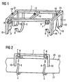
- the lifting device comprises a lifting frame 1 with a clamping device and a remotely controllable release mechanism.
- the clamping device comprises two seats 3 which are designed such that a turbine blade 23 can be pressed towards it with its trailing edge 25 ( Figure 2 ).
- It further comprises two belts 5 which are located at the frame 1 close to the seats 3 and which can be wound around the wind turbine blade 23 after the frame is lowered to the blade 23 with the seats 3 on the blade's trailing edge 25.
- One end of each belt 5 is permanently fixed to the frame 1 while the other end can be fitted into a combined gripping and tightening arrangement 7 which is fixed to the frame 1 on the side of the frame 1 which is opposite the side to which the belts are permanently fixed.
- the loose ends 9 of the belts 5 are inserted into the gripping and tightening arrangement 7 where they are then tightened and secured against slipping out.
- the gripping and tightening arrangement 7 is realised as a remotely controllable ratchet device which can, in particular, be unlocked by a remote action so that the ends 9 of the belts 5 can easily slip out of the ratchet mechanism, i.e. out of the gripping and tightening arrangement 7.
- the remote control unit for remotely unlocking the ratchet mechanism 7 is indicated by block 8 in Figures 1 and 2 .
- the seats 3 are realised by a flexible element 11, e.g. rubber elements, located between legs 10 of the frame 1. They have openings 13 which are adapted to the shape of the trailing edge 25 of the wind turbine blade 23 to be lifted.
- the seats could, in principle, instead have openings which are adapted to the shape of the blade's leading edge, its pressure side or its suction side.
- a ring 17 is mounted to which a wire 33 ( Figure 4 ) for bearing the weight and the lifting device and the blade attached thereto can be fixed.
- Second rings 19 are present at outer crossbars 21 of the frame 1 to which control wires (31) can be fixed for controlling the orientation of a blade attached to the lifting device.
- the lifting device is attached to a wind turbine rotor blade 23 when the blade 23 rests on the ground.
- the blade 23 rests such that its trailing edge 25 shows upwards.
- the belts 5 are wound around the blade's leading edge 27, then the loose ends 9 of the belts 5 are introduced into the ratchet mechanism 7 and then the belts 5 are tightened.
- the ratchet mechanism locks so as to prevent the belts 5 from slipping out of the ratchet mechanism if not an explicit release or unlocking operation is performed by remote control.
- the blade 23 is firmly fixed to the frame 1 of the lifting device by tightening of the belts or straps.
- the tightening arrangement may be independent, or it may be part of the release mechanism, as it is in the present embodiment.
- Figure 3 shows a section through the wind turbine blade 23 after it has been attached to the lifting device.
- FIG 4 shows a wind turbine blade 23 when it is being mounted on a rotor hub 9 of a wind turbine.
- the blade 23 which is shown to be mounted to the hub 29 in Figure 4 is the last blade of the rotor to be mounted.
- the rotor hub is rotated such that the blade 23 can be mounted in a horizontal position.
- the horizontal orientation of the blade can be controlled by control wires 31 which are fixed to the rings 19 at the outer crossbars 21 of the frame 1.
- the weight of the blade 23 and the lifting device are carried by a central holding wire 33 which is fixed to the ring 17 at the central crossbar 15 of the frame 1. All three wires are carried by a crane boom 35 which is used to lift the blade off the ground and to bring it into a position which is suitable for mounting it on the rotor hub 29.
- a remote control signal is sent to the remotely controllable ratchet mechanism 7 for unlocking it so as to release the gripping and tightening force of the ratchet mechanism 7.
- the control signal may be sent by the crane operator which has the advantage that the whole dismounting action is controlled by a single person so that no coordination between different persons is necessary.
- the release control signal is sent by another person, for example the person who is responsible for fixing the blade to the hub 29.
- the number of belts is not restricted to two. More or less than two belts are also possible. However, if only one belt is used the belt should be rather broad. It could, for example, extend over the whole distance between the outer crossbars 21. If more than one belt is used it is not necessary that the gripping and tightening arrangement 7 is located at the same side of the frame for each belt. In addition, it may even be possible to have belts which are not permanently fixed to the frame 1. In this case a further gripping and tightening arrangement or at least a further gripping arrangement would be present at the frame 1 for each belt 5.
- the release control signal could be sent to the gripping and tightening arrangements 7 either wirelessly or by a signal wire which could extend from the crane boom to the frame 1.
- the tightening action could be triggered by a remote signal.
- seats are only present at the outer crossbars in the present embodiment further seats could be present as well.
- a third seat could be present at the central crossbar 15.
- the rotor hub 29 is mounted to the nacelle of a wind turbine before the wind turbine blades 23 are mounted on the rotor hub.
- Mounting the rotor hub 29 on the nacelle can either be done before or after mounting the nacelle at the tower top of the wind turbine.
- a crane will be used for lifting the rotor hub to the nacelle. This crane may be the same crane which will later be used for mounting the wind turbine blades 23 on the rotor hub 29.
Landscapes
- Engineering & Computer Science (AREA)
- Mechanical Engineering (AREA)
- Life Sciences & Earth Sciences (AREA)
- Sustainable Development (AREA)
- Sustainable Energy (AREA)
- Chemical & Material Sciences (AREA)
- Combustion & Propulsion (AREA)
- General Engineering & Computer Science (AREA)
- Wind Motors (AREA)
- Load-Engaging Elements For Cranes (AREA)
Priority Applications (14)
| Application Number | Priority Date | Filing Date | Title |
|---|---|---|---|
| EP07013725.2A EP1925583B2 (en) | 2006-11-23 | 2007-07-12 | Method of handling wind turbine blades and device for mounting wind turbine blades, in particular mounting blades on a wind turbine |
| US11/986,036 US9475677B2 (en) | 2006-11-23 | 2007-11-19 | Method of handling wind turbine blades and device for mounting wind turbine blades, in particular mounting blades on a wind turbine |
| JP2007300141A JP5235388B2 (ja) | 2006-11-23 | 2007-11-20 | 風力タービンブレードの取り扱い方法、及び、風力タービンブレードを取り付けるための、とりわけ、風力タービンにブレードを取り付けるための装置 |
| CA2611342A CA2611342C (en) | 2006-11-23 | 2007-11-21 | Method of handling wind turbine blades and device for mounting wind turbine blades, in particular mounting blades on a wind turbine |
| AT07856251T ATE497474T1 (de) | 2006-11-23 | 2007-11-23 | Verfahren und vorrichtung zur montage von windturbinenschaufeln |
| CN2007101936273A CN101220798B (zh) | 2006-11-23 | 2007-11-23 | 操纵风力涡轮机叶片的方法和安装风力涡轮机叶片的装置 |
| EP07856251.9A EP2084098B2 (en) | 2006-11-23 | 2007-11-23 | Method and device for mounting of wind turbine blades |
| CN2007800434988A CN101541660B (zh) | 2006-11-23 | 2007-11-23 | 安装风力涡轮机叶片的方法和设备 |
| US12/515,805 US8601688B2 (en) | 2006-11-23 | 2007-11-23 | Method and device for mounting of wind turbine blades |
| DK07856251.9T DK2084098T4 (da) | 2006-11-23 | 2007-11-23 | Fremgangsmåde og indretning til montering af vindmøllevinger. |
| DE602007012362T DE602007012362D1 (de) | 2006-11-23 | 2007-11-23 | Verfahren und vorrichtung zur montage von windturbinenschaufeln |
| PCT/EP2007/010221 WO2008061797A1 (en) | 2006-11-23 | 2007-11-23 | Method and device for mounting of wind turbine blades |
| ES07856251T ES2356024T5 (es) | 2006-11-23 | 2007-11-23 | Procedimiento y dispositivo para el montaje de palas de turbina eólica |
| US14/041,556 US9009964B2 (en) | 2006-11-23 | 2013-09-30 | Device for mounting of wind turbine blades |
Applications Claiming Priority (3)
| Application Number | Priority Date | Filing Date | Title |
|---|---|---|---|
| EP06024336 | 2006-11-23 | ||
| EP06024337 | 2006-11-23 | ||
| EP07013725.2A EP1925583B2 (en) | 2006-11-23 | 2007-07-12 | Method of handling wind turbine blades and device for mounting wind turbine blades, in particular mounting blades on a wind turbine |
Publications (3)
| Publication Number | Publication Date |
|---|---|
| EP1925583A1 EP1925583A1 (en) | 2008-05-28 |
| EP1925583B1 EP1925583B1 (en) | 2010-04-07 |
| EP1925583B2 true EP1925583B2 (en) | 2013-05-15 |
Family
ID=42105485
Family Applications (1)
| Application Number | Title | Priority Date | Filing Date |
|---|---|---|---|
| EP07013725.2A Active EP1925583B2 (en) | 2006-11-23 | 2007-07-12 | Method of handling wind turbine blades and device for mounting wind turbine blades, in particular mounting blades on a wind turbine |
Country Status (9)
| Country | Link |
|---|---|
| US (1) | US9475677B2 (ja) |
| EP (1) | EP1925583B2 (ja) |
| JP (1) | JP5235388B2 (ja) |
| CN (1) | CN101220798B (ja) |
| AT (1) | ATE471909T1 (ja) |
| CA (1) | CA2611342C (ja) |
| DE (2) | DE602007007279D1 (ja) |
| DK (2) | DK1925583T4 (ja) |
| ES (2) | ES2339882T5 (ja) |
Families Citing this family (75)
| Publication number | Priority date | Publication date | Assignee | Title |
|---|---|---|---|---|
| CN101631954B (zh) | 2007-01-24 | 2012-10-03 | 维斯塔斯风力系统有限公司 | 将风轮机部件如风轮机轮毂从运输位置移动到在机舱、主轴或轮毂之中或之上的装配位置的方法,处理装置,风轮机轮毂及其使用 |
| DE102008053404A1 (de) | 2008-10-27 | 2010-04-29 | Ed. Züblin Ag | Verfahren zum Transport eines Rotorblatts einer Windenergieanlage und Transportvorrichtung zur Durchführung des Verfahrens |
| DE102009005632B4 (de) * | 2009-01-21 | 2017-06-01 | Senvion Gmbh | Handhabung von Rotorblättern |
| EP2228170A1 (de) * | 2009-03-12 | 2010-09-15 | Siemens Aktiengesellschaft | Werkstückspannvorrichtung mit Spanngurt |
| DK2424811T3 (da) | 2009-04-29 | 2014-01-27 | Siemens Ag | Vingeløftesystem med saloondøre |
| DE112010004168T5 (de) | 2009-10-30 | 2012-12-27 | Siemens Aktiengesellschaft | Rotorblatt-Demontagesystem mit Bandbewegung |
| DK2345811T3 (da) * | 2010-01-14 | 2012-11-19 | Siemens Ag | Klemme til klemning af et blad til en vindturbine og fremgangsmåde til installering af vindturbineblade |
| DE202010003033U1 (de) | 2010-02-17 | 2010-05-27 | Nordex Energy Gmbh | Hebezeug zur Positionierung eines Rotorblatts einer Windenergieanlage |
| JP4547039B1 (ja) * | 2010-02-23 | 2010-09-22 | 株式会社日本製鋼所 | 風力発電用ローターブレードの取り付け方法 |
| DE202010012237U1 (de) * | 2010-09-06 | 2011-12-08 | Liebherr-Werk Ehingen Gmbh | Kran |
| DE202010015616U1 (de) * | 2010-11-18 | 2012-03-01 | Liebherr-Werk Ehingen Gmbh | Kran |
| EP2369174B1 (en) * | 2010-03-09 | 2012-11-28 | Lm Glasfiber A/S | A method of craneless mounting or demounting of a wind turbine blade |
| DE202010004093U1 (de) * | 2010-03-23 | 2011-05-05 | Wobben, Aloys, Dipl.-Ing. | Hebeeinheit zum Heben eines Rotors einer Windenergieanlage |
| AU2010276465A1 (en) * | 2010-05-31 | 2011-12-15 | Mitsubishi Heavy Industries, Ltd. | A blade end portion protecting bag and a rotor installing method for a wind turbine |
| NL2004987C2 (nl) | 2010-06-28 | 2011-12-29 | Ihc Holland Ie Bv | Liftinrichting en werkwijze voor het positioneren van een log object. |
| ES1073014Y (es) * | 2010-07-29 | 2011-03-01 | Acciona Windpower Sa | Uil para elevacion y descenso de una pala de aerogenerador |
| DK2434142T3 (da) * | 2010-09-27 | 2013-06-24 | Siemens Ag | Fremgangsmåde, enhed og system til montering af vindmøllevinger på et vindmøllenav |
| CN101986111A (zh) * | 2010-10-13 | 2011-03-16 | 济南轨道交通装备有限责任公司 | 一种风力发电机叶片配平衡用称量系统 |
| JP2012112352A (ja) * | 2010-11-26 | 2012-06-14 | Mitsubishi Heavy Ind Ltd | タービン装置の分解組立要具およびタービン装置の分解組立方法 |
| EP2487363A1 (en) * | 2011-01-31 | 2012-08-15 | Siemens Aktiengesellschaft | Lifting system and method for lifting rotor blades of wind turbines |
| EP2532890A4 (en) | 2011-04-05 | 2013-06-19 | Mitsubishi Heavy Ind Ltd | DEVICE FOR GENERATING ELECTRICITY FROM REGENERATED ENERGY |
| DK2532879T3 (da) * | 2011-06-07 | 2014-04-07 | Siemens Ag | Montering og/eller vedligeholdelse af en vindmølle |
| DE102011116189B3 (de) | 2011-06-21 | 2012-10-04 | Repower Systems Se | Lasthandhabungsvorrichtung zum Anheben von Rotorblättern in eine Montageposition und Verfahren zur Montage von Rotorblättern an der Rotornabe einer Windenergieanlage |
| CN102251938B (zh) * | 2011-07-07 | 2013-04-24 | 中国十七冶集团有限公司 | 风力发电机叶片保护装置 |
| KR101220068B1 (ko) * | 2011-08-10 | 2013-01-09 | 한전케이피에스 주식회사 | 가스터빈 연소실 바스켓 취외장치 |
| JP4950367B1 (ja) | 2011-08-10 | 2012-06-13 | 三菱重工業株式会社 | 再生エネルギー型発電装置 |
| FR2979335B1 (fr) * | 2011-08-22 | 2015-11-13 | Degremont | Dispositif pour manipuler un objet allonge, en particulier un module de filtration membranaire, et procede de manipulation mettant en oeuvre ce dispositif |
| US8595931B2 (en) * | 2011-08-22 | 2013-12-03 | General Electric Company | Lift system and method for constructing a wind turbine |
| EP2587055B1 (en) | 2011-09-22 | 2014-02-12 | Mitsubishi Heavy Industries, Ltd. | Regenerated-energy power generation device and rotary wing attachment/detachment method therefor |
| JP5575224B2 (ja) * | 2011-09-22 | 2014-08-20 | 三菱重工業株式会社 | 再生エネルギー型発電装置の回転翼取付方法 |
| DK2589795T3 (en) | 2011-11-04 | 2015-03-30 | Siemens Ag | Lifting frame for lifting a wind turbine rotor blade and the method of mounting vindmøllerotorvinger |
| DK2604568T3 (da) * | 2011-12-14 | 2014-05-05 | Siemens Ag | Kombineret løftebomindretning til vindmølledele |
| CN104136358B (zh) * | 2011-12-22 | 2015-12-16 | 维斯塔斯风力系统有限公司 | 用于在运输与装配过程中搬运风轮机部件的方法及设备 |
| DE102012201088A1 (de) * | 2012-01-25 | 2013-07-25 | Wobben Properties Gmbh | Verfahren und Vorrichtung zum Montieren einer Rotornabe einer Windenergieanlage |
| ITBZ20120013A1 (it) | 2012-04-18 | 2013-10-19 | Ars Meccanica Dolomiti G M B H S R L | Meccanismo prensile per sollevatori |
| PT2890626T (pt) * | 2012-08-30 | 2019-10-14 | High Wind N V | Dispositivo e método para montagem de uma estrutura |
| DK2708734T3 (en) * | 2012-09-13 | 2017-02-13 | Alstom Renewable Technologies | Wind turbine blades and methods for transporting, storing and installing wind turbine blades |
| DE102012109403B3 (de) * | 2012-10-02 | 2014-03-06 | Repower Systems Se | Verfahren zur Montage eines Rotorblattes und Montageanordnung |
| WO2014076824A1 (ja) * | 2012-11-16 | 2014-05-22 | 三菱重工業株式会社 | 風車翼把持機構、及び、風力発電装置の組立方法 |
| CN102963824A (zh) * | 2012-11-22 | 2013-03-13 | 昆山华风风电科技有限公司 | 风机叶片吊装运输装置 |
| ES2636289T3 (es) * | 2012-11-30 | 2017-10-05 | Areva Wind Gmbh | Elevador para manipular una pala de rotor de una turbina eólica y procedimiento de funcionamiento del mismo |
| DK2935080T3 (en) | 2012-12-20 | 2018-05-28 | High Wind N V | Apparatus and method for placing components of a structure |
| EP2956400B1 (en) * | 2013-02-18 | 2018-02-14 | High Wind N.V. | Device and method for placing a rotor blade of a wind turbine |
| US20150028608A1 (en) * | 2013-07-29 | 2015-01-29 | General Electric Company | Method and apparatus for handling a rotor blade |
| EP2832675B1 (en) * | 2013-07-29 | 2018-07-04 | Siemens Aktiengesellschaft | Blade gripping device |
| EP2832677B1 (en) | 2013-07-29 | 2016-05-25 | Siemens Aktiengesellschaft | Blade gripping tool and device |
| KR101408274B1 (ko) | 2013-08-09 | 2014-06-16 | 임영택 | 풍력발전기 블레이드의 수평이동장치 |
| KR101338407B1 (ko) * | 2013-08-09 | 2013-12-06 | 임영택 | 풍력발전기 블레이드의 이동장치 |
| EP2889251B1 (en) | 2013-12-30 | 2016-08-24 | Siemens Aktiengesellschaft | Load guiding arrangement |
| CN103723614B (zh) * | 2014-01-24 | 2016-03-02 | 江苏金风科技有限公司 | 一种风力发电机组叶片30度角安装吊具及其吊装方法 |
| CN104646918B (zh) * | 2015-01-16 | 2017-04-19 | 南车株洲电力机车研究所有限公司 | 一种风力发电机组叶片的更换方法 |
| GB201523121D0 (en) | 2015-12-30 | 2016-02-10 | Vestas Wind Sys As | Transport frame for a turbine blade |
| CN105649893B (zh) * | 2016-03-08 | 2018-07-17 | 中国船舶重工集团公司第七一九研究所 | 一种风力涡轮机叶片的拆卸系统和方法 |
| CN105936476A (zh) * | 2016-04-15 | 2016-09-14 | 国网天津市电力公司 | 一种风电场叶片改造施工方法 |
| WO2017217845A1 (en) * | 2016-06-15 | 2017-12-21 | Itrec B.V. | A crane for wind turbine blade assembly, a vessel, a hoisting method, and an assembly method |
| CN106044539B (zh) * | 2016-06-24 | 2018-05-15 | 成都世唯科技有限公司 | 一种带吊带收紧机构的风叶吊具支架 |
| CN109996750B (zh) | 2016-10-20 | 2021-10-29 | 西门子歌美飒可再生能源公司 | 用于风力涡轮机部件的提升装置和方法 |
| US10457422B2 (en) * | 2016-12-07 | 2019-10-29 | Sikorsky Aircraft Corporation | Weights for water immersion testing |
| NL1042325B1 (en) * | 2017-04-03 | 2018-10-11 | Lagerwey Wind B V | Hoisting System for Installing a Wind Turbine |
| CN107150946B (zh) * | 2017-06-29 | 2018-04-10 | 湖北三江航天江河化工科技有限公司 | 一种翼板起吊装置及其吊装方法 |
| DE102017010712A1 (de) * | 2017-11-20 | 2019-05-23 | Senvion Gmbh | Spanngurt an Windenergieanlagen |
| ES2836706T3 (es) | 2017-11-21 | 2021-06-28 | Siemens Gamesa Renewable Energy As | Estructura de soporte para pala de turbina eólica |
| CN108439183A (zh) * | 2018-04-05 | 2018-08-24 | 南京高传机电自动控制设备有限公司 | 一种叶片吊装结构 |
| CN109139389B (zh) * | 2018-08-02 | 2020-01-10 | 大连理工大学 | 用于风机单叶片安装的主动反馈控制方法和装置 |
| DE102018126728A1 (de) | 2018-10-26 | 2020-04-30 | Wobben Properties Gmbh | Verfahren zur Montage eines Windenergieanlagen-Rotorblattes |
| CN109704186B (zh) * | 2018-12-28 | 2023-02-28 | 江苏金风科技有限公司 | 叶片更换工装 |
| EP3902764A1 (en) * | 2018-12-28 | 2021-11-03 | Vestas Wind Systems A/S | A method for handling a wind turbine component with a control arrangement |
| EP3983329A1 (en) * | 2019-06-11 | 2022-04-20 | Vestas Wind Systems A/S | Method for handling a wind turbine component and associated lifting system |
| NL2026416B1 (en) * | 2020-09-04 | 2022-05-04 | Tetrahedron B V | Crane vessel with a crane for hoisting wind turbine components |
| CN114906708B (zh) * | 2021-02-08 | 2024-01-23 | 江苏金风科技有限公司 | 叶片吊装设备 |
| CN113104725B (zh) * | 2021-04-13 | 2022-09-16 | 上海杰碧管道工程有限公司 | 一种新型深水打捞用吊装夹具 |
| DE102022104895A1 (de) | 2022-03-02 | 2023-09-07 | Hawart Sondermaschinenbau Gmbh | Hebevorrichtung zum Anheben eines Rotorblattes und Haltevorrichtung dafür |
| WO2023193880A1 (de) * | 2022-04-04 | 2023-10-12 | Otto Kabilka | Greifwerkzeug zum greifen eines rotorblatts für einen helikopter sowie montagestation und verfahren zum montieren eines rotorblatts an einem helikopter |
| CN115432611B (zh) * | 2022-09-01 | 2023-09-08 | 凯盛重工有限公司 | 一种通过手柄调速的矿用无极绳绞车电控装置 |
| CN116906271B (zh) * | 2023-09-12 | 2023-12-05 | 常州亿麟电气科技有限公司 | 一种风电叶片安装装置 |
Family Cites Families (36)
| Publication number | Priority date | Publication date | Assignee | Title |
|---|---|---|---|---|
| US3858728A (en) | 1974-01-11 | 1975-01-07 | Midland Ross Corp | Radio control crane and spreader system for handling containers |
| GB1583567A (en) | 1976-09-13 | 1981-01-28 | Androski Edward C | Remotecontrolled safety hook assembly |
| US4073531A (en) | 1976-09-13 | 1978-02-14 | Androski Edward C | Remote-controlled safety hook assembly |
| US4293155A (en) | 1979-11-19 | 1981-10-06 | Weyerhaeuser Company | Log handling and transport system |
| US4416480A (en) | 1981-09-08 | 1983-11-22 | Cranston Machinery Co., Inc. | Pneumatic release for load hook |
| DE3137790C1 (de) | 1981-09-23 | 1983-02-24 | Ernst Dr.-Ing. 4300 Essen Haeussler | Vorrichtung zum Manipulieren eines Stahlbetonfertigteils mit Hilfe eines Hebezeuges |
| DE3222819C1 (de) | 1982-06-18 | 1983-11-17 | Ernst Dr.-Ing. 4300 Essen Haeussler | Vorrichtung zum Manipulieren eines Stahlbetonfertigteils |
| DE3419363A1 (de) | 1984-05-24 | 1985-11-28 | Kaup GmbH & Co KG Gesellschaft für Maschinenbau, 8750 Aschaffenburg | Trageinrichtung fuer container |
| DD241583A1 (de) | 1985-10-03 | 1986-12-17 | Pieck W Wohnbauk Veb | Vorrichtung zur fernbedienbaren entsperrung von falltaschen bei lastaufnahmemitteln |
| US4818004A (en) * | 1987-11-16 | 1989-04-04 | Mcdonnell Douglas Corporation | Rotor blade sling |
| SE462619B (sv) | 1988-12-06 | 1990-07-30 | Cool Carriers Svenska Ab | Anordning foer lossning av lasten vid lastupphaengningsdon |
| JP2692919B2 (ja) | 1988-12-22 | 1997-12-17 | 株式会社大滝油圧 | 斜張橋のケーブル架設工法に使用するケーブル保持装置 |
| JP2741249B2 (ja) * | 1989-05-31 | 1998-04-15 | 三和テッキ株式会社 | クレーン用吊り帯装置 |
| DE4423335C2 (de) | 1994-06-20 | 1996-07-25 | Mannesmann Ag | Verfahren und Lastaufnahmemittel zum Ein- und Aushängen von Aufhänge-Ösen |
| US5772269A (en) * | 1996-09-30 | 1998-06-30 | Mcconnell Douglas Corporation | Hoisting tool |
| KR100314143B1 (ko) * | 1995-08-30 | 2001-12-28 | 튜보 린타마키, 타피오 하카카리 | 크레인의 로드와 로딩부 제어 장치 및 제어 방법 |
| US5895083A (en) * | 1995-09-14 | 1999-04-20 | James D. Bidwell | Automatic cable disconnector |
| NL1010035C2 (nl) | 1998-09-08 | 2000-06-06 | Imc Group B V | Op afstand bedienbare hijshaak. |
| NO311816B1 (no) | 2000-04-13 | 2002-01-28 | Knut Ove Steinhovden | Utlösbar låseanordning for mekanisk kopling |
| NO313003B1 (no) | 2000-05-19 | 2002-07-29 | Knut Ove Steinhovden | Oppdriftsutlösbar mekanisk kopling |
| GB2378431A (en) | 2001-06-07 | 2003-02-12 | Jeremy James Cathcart | Apparatus for handling bulk material. |
| DE20109835U1 (de) | 2001-06-15 | 2002-01-24 | Gerken Gmbh | Arbeitsbühne |
| ES2295398T3 (es) * | 2001-07-20 | 2008-04-16 | Aloys Wobben | Procedimiento para la construccion in situ de una instalacion de energia eolica. |
| DE60209494T2 (de) | 2002-05-27 | 2006-08-24 | Vestas Wind Systems A/S | Verfahren zur handhabung von windturbinenschaufeln und zur anbringung der genannten schaufeln an einer windturbine, system und greifeinheit zur handhabung einer windturbinenschaufel |
| US20060120809A1 (en) | 2002-05-28 | 2006-06-08 | James Ingram | Method and crane for installing, maintaining and decommissioning wind turbines |
| DE10225025A1 (de) | 2002-06-06 | 2003-12-24 | Aloys Wobben | Vorrichtung zum Handhaben von Rotorblättern |
| EP1534953A1 (en) | 2002-09-04 | 2005-06-01 | PP Energy ApS | A method and a device for lifting and/or lowering of objects at a wind turbine or the like and uses hereof |
| DE10305543C5 (de) | 2003-02-10 | 2011-04-28 | Aloys Wobben | Verfahren zur Montage von Rotorblättern sowie ein Rotorblatt für eine Windenergieanlage |
| AU2004314364B2 (en) | 2004-01-26 | 2008-08-07 | Vestas Wind Systems A/S | Methods of handling a wind turbine blade and system therefor |
| JP2005255583A (ja) | 2004-03-10 | 2005-09-22 | Kuraray Co Ltd | ラクトン骨格含有(メタ)アクリル酸エステルの製造方法 |
| WO2005104787A2 (en) | 2004-04-28 | 2005-11-10 | Protesto Edward R | Crane hook with remotely operated safety latch release |
| DE202004016460U1 (de) * | 2004-10-25 | 2004-12-23 | Geo. Gleistein & Sohn Gmbh | Vorrichtung zum Austauschen eines Rotorblatts einer Windkraftanlage |
| US7380849B2 (en) | 2004-10-25 | 2008-06-03 | The Caldwell Group, Inc. | Remote release apparatus and method for lifting and releasing a load |
| BRPI0405546F1 (pt) | 2004-12-10 | 2016-03-22 | Tecsis Tecnologia E Sist S Avançados Ltda | desenvolvimento em conjunto de estruturas para manuseio, transporte e armazenamento de pás para rotores de aerogeradores |
| EP1925582B1 (en) * | 2006-11-23 | 2010-06-23 | Siemens Aktiengesellschaft | Method and a device for mounting of wind turbine blades |
| US8595931B2 (en) * | 2011-08-22 | 2013-12-03 | General Electric Company | Lift system and method for constructing a wind turbine |
-
2007
- 2007-07-12 DK DK07013725.2T patent/DK1925583T4/da active
- 2007-07-12 EP EP07013725.2A patent/EP1925583B2/en active Active
- 2007-07-12 DE DE602007007279T patent/DE602007007279D1/de active Active
- 2007-07-12 ES ES07013725T patent/ES2339882T5/es active Active
- 2007-07-12 ES ES07013724T patent/ES2343819T3/es active Active
- 2007-07-12 AT AT07013724T patent/ATE471909T1/de not_active IP Right Cessation
- 2007-07-12 DK DK07013724.5T patent/DK1925582T3/da active
- 2007-07-12 DE DE602007005751T patent/DE602007005751D1/de active Active
- 2007-11-19 US US11/986,036 patent/US9475677B2/en active Active
- 2007-11-20 JP JP2007300141A patent/JP5235388B2/ja active Active
- 2007-11-21 CA CA2611342A patent/CA2611342C/en active Active
- 2007-11-23 CN CN2007101936273A patent/CN101220798B/zh active Active
Also Published As
| Publication number | Publication date |
|---|---|
| JP5235388B2 (ja) | 2013-07-10 |
| DK1925582T3 (da) | 2010-09-20 |
| ES2343819T3 (es) | 2010-08-10 |
| ES2339882T5 (es) | 2013-07-26 |
| EP1925583B1 (en) | 2010-04-07 |
| JP2008128253A (ja) | 2008-06-05 |
| DE602007007279D1 (de) | 2010-08-05 |
| EP1925583A1 (en) | 2008-05-28 |
| US9475677B2 (en) | 2016-10-25 |
| CN101220798B (zh) | 2013-02-27 |
| CA2611342A1 (en) | 2008-05-23 |
| US20090025219A1 (en) | 2009-01-29 |
| DK1925583T4 (da) | 2013-07-15 |
| ES2339882T3 (es) | 2010-05-26 |
| DK1925583T3 (da) | 2010-07-26 |
| CN101220798A (zh) | 2008-07-16 |
| CA2611342C (en) | 2015-03-17 |
| DE602007005751D1 (de) | 2010-05-20 |
| ATE471909T1 (de) | 2010-07-15 |
Similar Documents
| Publication | Publication Date | Title |
|---|---|---|
| EP1925583B2 (en) | Method of handling wind turbine blades and device for mounting wind turbine blades, in particular mounting blades on a wind turbine | |
| JP2008128253A6 (ja) | 風力タービンブレードの取り扱い方法、及び、風力タービンブレードを取り付けるための、とりわけ、風力タービンにブレードを取り付けるための装置 | |
| US20100139062A1 (en) | Lowering and raising a single wind turbine rotor blade from six-o'clock position | |
| US8161693B2 (en) | Method and arrangement to install a wind-turbine | |
| JP5420165B2 (ja) | 風力タービンブレードの取り付け方法及び装置 | |
| US20140010658A1 (en) | Method for craneless wind turbine blade handling via a turbine hub | |
| US11454217B2 (en) | System for craneless blade mounting and dismounting at wind turbines | |
| US9745953B2 (en) | Method and system for replacing a single wind turbine blade | |
| EP2661550B1 (en) | Wind turbine blade bearing removal apparatus and method | |
| WO2012062352A1 (en) | Lifting beam for use in hoisting a wind turbine blade | |
| CN110036198A (zh) | 转子叶片组件 | |
| EP3088732B1 (en) | Method and system for replacing a single wind turbine blade | |
| EP4007850B1 (en) | Clamp for wind turbine rotor blade | |
| JP5663249B2 (ja) | 風力発電装置のブレード吊上方法及びブレード吊上治具 | |
| US11466665B2 (en) | Method for installing a wind turbine rotor blade | |
| WO2019042510A1 (en) | WORK PLATFORM SYSTEM AND METHOD FOR MOUNTING WORK PLATFORM SYSTEM | |
| CN110249128B (zh) | 用于平行于风力涡轮机塔架升高或降低负载的方法和设备 | |
| US20210032081A1 (en) | Blade Crane |
Legal Events
| Date | Code | Title | Description |
|---|---|---|---|
| PUAI | Public reference made under article 153(3) epc to a published international application that has entered the european phase |
Free format text: ORIGINAL CODE: 0009012 |
|
| AK | Designated contracting states |
Kind code of ref document: A1 Designated state(s): AT BE BG CH CY CZ DE DK EE ES FI FR GB GR HU IE IS IT LI LT LU LV MC MT NL PL PT RO SE SI SK TR |
|
| AX | Request for extension of the european patent |
Extension state: AL BA HR MK RS |
|
| 17P | Request for examination filed |
Effective date: 20080710 |
|
| AKX | Designation fees paid |
Designated state(s): DE DK ES FR GB SE |
|
| GRAP | Despatch of communication of intention to grant a patent |
Free format text: ORIGINAL CODE: EPIDOSNIGR1 |
|
| GRAS | Grant fee paid |
Free format text: ORIGINAL CODE: EPIDOSNIGR3 |
|
| GRAA | (expected) grant |
Free format text: ORIGINAL CODE: 0009210 |
|
| AK | Designated contracting states |
Kind code of ref document: B1 Designated state(s): DE DK ES FR GB SE |
|
| REG | Reference to a national code |
Ref country code: GB Ref legal event code: FG4D |
|
| REF | Corresponds to: |
Ref document number: 602007005751 Country of ref document: DE Date of ref document: 20100520 Kind code of ref document: P |
|
| REG | Reference to a national code |
Ref country code: ES Ref legal event code: FG2A Ref document number: 2339882 Country of ref document: ES Kind code of ref document: T3 |
|
| REG | Reference to a national code |
Ref country code: SE Ref legal event code: TRGR |
|
| REG | Reference to a national code |
Ref country code: DK Ref legal event code: T3 |
|
| PLBI | Opposition filed |
Free format text: ORIGINAL CODE: 0009260 |
|
| PLAX | Notice of opposition and request to file observation + time limit sent |
Free format text: ORIGINAL CODE: EPIDOSNOBS2 |
|
| 26 | Opposition filed |
Opponent name: NORDEX ENERGY GMBH Effective date: 20110107 Opponent name: VESTAS WIND SYSTEMS A/S Effective date: 20110107 Opponent name: GKS STAHL- UND MASCHINENBAU GMBH Effective date: 20110107 Opponent name: REPOWER SYSTEMS AG Effective date: 20110107 |
|
| PLBB | Reply of patent proprietor to notice(s) of opposition received |
Free format text: ORIGINAL CODE: EPIDOSNOBS3 |
|
| APAH | Appeal reference modified |
Free format text: ORIGINAL CODE: EPIDOSCREFNO |
|
| APBM | Appeal reference recorded |
Free format text: ORIGINAL CODE: EPIDOSNREFNO |
|
| APBP | Date of receipt of notice of appeal recorded |
Free format text: ORIGINAL CODE: EPIDOSNNOA2O |
|
| APBM | Appeal reference recorded |
Free format text: ORIGINAL CODE: EPIDOSNREFNO |
|
| APBP | Date of receipt of notice of appeal recorded |
Free format text: ORIGINAL CODE: EPIDOSNNOA2O |
|
| APAY | Date of receipt of notice of appeal deleted |
Free format text: ORIGINAL CODE: EPIDOSDNOA2O |
|
| APBM | Appeal reference recorded |
Free format text: ORIGINAL CODE: EPIDOSNREFNO |
|
| APBP | Date of receipt of notice of appeal recorded |
Free format text: ORIGINAL CODE: EPIDOSNNOA2O |
|
| APBU | Appeal procedure closed |
Free format text: ORIGINAL CODE: EPIDOSNNOA9O |
|
| RAP2 | Party data changed (patent owner data changed or rights of a patent transferred) |
Owner name: SIEMENS AKTIENGESELLSCHAFT |
|
| PUAH | Patent maintained in amended form |
Free format text: ORIGINAL CODE: 0009272 |
|
| STAA | Information on the status of an ep patent application or granted ep patent |
Free format text: STATUS: PATENT MAINTAINED AS AMENDED |
|
| 27A | Patent maintained in amended form |
Effective date: 20130515 |
|
| AK | Designated contracting states |
Kind code of ref document: B2 Designated state(s): DE DK ES FR GB SE |
|
| REG | Reference to a national code |
Ref country code: SE Ref legal event code: RPEO |
|
| REG | Reference to a national code |
Ref country code: DE Ref legal event code: R102 Ref document number: 602007005751 Country of ref document: DE Effective date: 20130515 |
|
| REG | Reference to a national code |
Ref country code: DK Ref legal event code: T4 |
|
| REG | Reference to a national code |
Ref country code: ES Ref legal event code: DC2A Ref document number: 2339882 Country of ref document: ES Kind code of ref document: T5 Effective date: 20130726 |
|
| REG | Reference to a national code |
Ref country code: FR Ref legal event code: PLFP Year of fee payment: 10 |
|
| REG | Reference to a national code |
Ref country code: FR Ref legal event code: PLFP Year of fee payment: 11 |
|
| REG | Reference to a national code |
Ref country code: FR Ref legal event code: PLFP Year of fee payment: 12 |
|
| REG | Reference to a national code |
Ref country code: DE Ref legal event code: R081 Ref document number: 602007005751 Country of ref document: DE Owner name: SIEMENS GAMESA RENEWABLE ENERGY A/S, DK Free format text: FORMER OWNER: SIEMENS AKTIENGESELLSCHAFT, 80333 MUENCHEN, DE |
|
| REG | Reference to a national code |
Ref country code: ES Ref legal event code: PC2A Owner name: SIEMENS GAMESA RENEWABLE ENERGY A/S Effective date: 20210311 |
|
| REG | Reference to a national code |
Ref country code: GB Ref legal event code: 732E Free format text: REGISTERED BETWEEN 20210722 AND 20210728 |
|
| P01 | Opt-out of the competence of the unified patent court (upc) registered |
Effective date: 20230530 |
|
| PGFP | Annual fee paid to national office [announced via postgrant information from national office to epo] |
Ref country code: GB Payment date: 20230724 Year of fee payment: 17 Ref country code: ES Payment date: 20230821 Year of fee payment: 17 |
|
| PGFP | Annual fee paid to national office [announced via postgrant information from national office to epo] |
Ref country code: SE Payment date: 20230724 Year of fee payment: 17 Ref country code: FR Payment date: 20230724 Year of fee payment: 17 Ref country code: DK Payment date: 20230724 Year of fee payment: 17 Ref country code: DE Payment date: 20230720 Year of fee payment: 17 |