EP2084098B2 - Method and device for mounting of wind turbine blades - Google Patents
Method and device for mounting of wind turbine blades Download PDFInfo
- Publication number
- EP2084098B2 EP2084098B2 EP07856251.9A EP07856251A EP2084098B2 EP 2084098 B2 EP2084098 B2 EP 2084098B2 EP 07856251 A EP07856251 A EP 07856251A EP 2084098 B2 EP2084098 B2 EP 2084098B2
- Authority
- EP
- European Patent Office
- Prior art keywords
- blade
- winch
- wind turbine
- control wire
- orientation
- Prior art date
- Legal status (The legal status is an assumption and is not a legal conclusion. Google has not performed a legal analysis and makes no representation as to the accuracy of the status listed.)
- Active
Links
- 238000000034 method Methods 0.000 title claims abstract description 27
- 230000001276 controlling effect Effects 0.000 description 33
- 238000004804 winding Methods 0.000 description 4
- 230000000284 resting effect Effects 0.000 description 2
- 238000010276 construction Methods 0.000 description 1
- 230000001105 regulatory effect Effects 0.000 description 1
- 238000004904 shortening Methods 0.000 description 1
- 230000007704 transition Effects 0.000 description 1
- 238000011144 upstream manufacturing Methods 0.000 description 1
Images


Classifications
-
- B—PERFORMING OPERATIONS; TRANSPORTING
- B66—HOISTING; LIFTING; HAULING
- B66C—CRANES; LOAD-ENGAGING ELEMENTS OR DEVICES FOR CRANES, CAPSTANS, WINCHES, OR TACKLES
- B66C23/00—Cranes comprising essentially a beam, boom, or triangular structure acting as a cantilever and mounted for translatory of swinging movements in vertical or horizontal planes or a combination of such movements, e.g. jib-cranes, derricks, tower cranes
- B66C23/18—Cranes comprising essentially a beam, boom, or triangular structure acting as a cantilever and mounted for translatory of swinging movements in vertical or horizontal planes or a combination of such movements, e.g. jib-cranes, derricks, tower cranes specially adapted for use in particular purposes
- B66C23/185—Cranes comprising essentially a beam, boom, or triangular structure acting as a cantilever and mounted for translatory of swinging movements in vertical or horizontal planes or a combination of such movements, e.g. jib-cranes, derricks, tower cranes specially adapted for use in particular purposes for use erecting wind turbines
-
- B—PERFORMING OPERATIONS; TRANSPORTING
- B66—HOISTING; LIFTING; HAULING
- B66C—CRANES; LOAD-ENGAGING ELEMENTS OR DEVICES FOR CRANES, CAPSTANS, WINCHES, OR TACKLES
- B66C1/00—Load-engaging elements or devices attached to lifting or lowering gear of cranes or adapted for connection therewith for transmitting lifting forces to articles or groups of articles
- B66C1/10—Load-engaging elements or devices attached to lifting or lowering gear of cranes or adapted for connection therewith for transmitting lifting forces to articles or groups of articles by mechanical means
- B66C1/108—Load-engaging elements or devices attached to lifting or lowering gear of cranes or adapted for connection therewith for transmitting lifting forces to articles or groups of articles by mechanical means for lifting parts of wind turbines
-
- B—PERFORMING OPERATIONS; TRANSPORTING
- B66—HOISTING; LIFTING; HAULING
- B66C—CRANES; LOAD-ENGAGING ELEMENTS OR DEVICES FOR CRANES, CAPSTANS, WINCHES, OR TACKLES
- B66C1/00—Load-engaging elements or devices attached to lifting or lowering gear of cranes or adapted for connection therewith for transmitting lifting forces to articles or groups of articles
- B66C1/10—Load-engaging elements or devices attached to lifting or lowering gear of cranes or adapted for connection therewith for transmitting lifting forces to articles or groups of articles by mechanical means
- B66C1/42—Gripping members engaging only the external or internal surfaces of the articles
-
- B—PERFORMING OPERATIONS; TRANSPORTING
- B66—HOISTING; LIFTING; HAULING
- B66C—CRANES; LOAD-ENGAGING ELEMENTS OR DEVICES FOR CRANES, CAPSTANS, WINCHES, OR TACKLES
- B66C13/00—Other constructional features or details
- B66C13/04—Auxiliary devices for controlling movements of suspended loads, or preventing cable slack
- B66C13/08—Auxiliary devices for controlling movements of suspended loads, or preventing cable slack for depositing loads in desired attitudes or positions
-
- B—PERFORMING OPERATIONS; TRANSPORTING
- B66—HOISTING; LIFTING; HAULING
- B66C—CRANES; LOAD-ENGAGING ELEMENTS OR DEVICES FOR CRANES, CAPSTANS, WINCHES, OR TACKLES
- B66C23/00—Cranes comprising essentially a beam, boom, or triangular structure acting as a cantilever and mounted for translatory of swinging movements in vertical or horizontal planes or a combination of such movements, e.g. jib-cranes, derricks, tower cranes
- B66C23/18—Cranes comprising essentially a beam, boom, or triangular structure acting as a cantilever and mounted for translatory of swinging movements in vertical or horizontal planes or a combination of such movements, e.g. jib-cranes, derricks, tower cranes specially adapted for use in particular purposes
- B66C23/36—Cranes comprising essentially a beam, boom, or triangular structure acting as a cantilever and mounted for translatory of swinging movements in vertical or horizontal planes or a combination of such movements, e.g. jib-cranes, derricks, tower cranes specially adapted for use in particular purposes mounted on road or rail vehicles; Manually-movable jib-cranes for use in workshops; Floating cranes
-
- F—MECHANICAL ENGINEERING; LIGHTING; HEATING; WEAPONS; BLASTING
- F03—MACHINES OR ENGINES FOR LIQUIDS; WIND, SPRING, OR WEIGHT MOTORS; PRODUCING MECHANICAL POWER OR A REACTIVE PROPULSIVE THRUST, NOT OTHERWISE PROVIDED FOR
- F03D—WIND MOTORS
- F03D13/00—Assembly, mounting or commissioning of wind motors; Arrangements specially adapted for transporting wind motor components
- F03D13/10—Assembly of wind motors; Arrangements for erecting wind motors
-
- F—MECHANICAL ENGINEERING; LIGHTING; HEATING; WEAPONS; BLASTING
- F03—MACHINES OR ENGINES FOR LIQUIDS; WIND, SPRING, OR WEIGHT MOTORS; PRODUCING MECHANICAL POWER OR A REACTIVE PROPULSIVE THRUST, NOT OTHERWISE PROVIDED FOR
- F03D—WIND MOTORS
- F03D13/00—Assembly, mounting or commissioning of wind motors; Arrangements specially adapted for transporting wind motor components
- F03D13/20—Arrangements for mounting or supporting wind motors; Masts or towers for wind motors
-
- F—MECHANICAL ENGINEERING; LIGHTING; HEATING; WEAPONS; BLASTING
- F03—MACHINES OR ENGINES FOR LIQUIDS; WIND, SPRING, OR WEIGHT MOTORS; PRODUCING MECHANICAL POWER OR A REACTIVE PROPULSIVE THRUST, NOT OTHERWISE PROVIDED FOR
- F03D—WIND MOTORS
- F03D13/00—Assembly, mounting or commissioning of wind motors; Arrangements specially adapted for transporting wind motor components
- F03D13/40—Arrangements or methods specially adapted for transporting wind motor components
-
- F—MECHANICAL ENGINEERING; LIGHTING; HEATING; WEAPONS; BLASTING
- F05—INDEXING SCHEMES RELATING TO ENGINES OR PUMPS IN VARIOUS SUBCLASSES OF CLASSES F01-F04
- F05B—INDEXING SCHEME RELATING TO WIND, SPRING, WEIGHT, INERTIA OR LIKE MOTORS, TO MACHINES OR ENGINES FOR LIQUIDS COVERED BY SUBCLASSES F03B, F03D AND F03G
- F05B2230/00—Manufacture
- F05B2230/60—Assembly methods
- F05B2230/61—Assembly methods using auxiliary equipment for lifting or holding
-
- F—MECHANICAL ENGINEERING; LIGHTING; HEATING; WEAPONS; BLASTING
- F05—INDEXING SCHEMES RELATING TO ENGINES OR PUMPS IN VARIOUS SUBCLASSES OF CLASSES F01-F04
- F05B—INDEXING SCHEME RELATING TO WIND, SPRING, WEIGHT, INERTIA OR LIKE MOTORS, TO MACHINES OR ENGINES FOR LIQUIDS COVERED BY SUBCLASSES F03B, F03D AND F03G
- F05B2250/00—Geometry
- F05B2250/30—Arrangement of components
-
- Y—GENERAL TAGGING OF NEW TECHNOLOGICAL DEVELOPMENTS; GENERAL TAGGING OF CROSS-SECTIONAL TECHNOLOGIES SPANNING OVER SEVERAL SECTIONS OF THE IPC; TECHNICAL SUBJECTS COVERED BY FORMER USPC CROSS-REFERENCE ART COLLECTIONS [XRACs] AND DIGESTS
- Y02—TECHNOLOGIES OR APPLICATIONS FOR MITIGATION OR ADAPTATION AGAINST CLIMATE CHANGE
- Y02E—REDUCTION OF GREENHOUSE GAS [GHG] EMISSIONS, RELATED TO ENERGY GENERATION, TRANSMISSION OR DISTRIBUTION
- Y02E10/00—Energy generation through renewable energy sources
- Y02E10/70—Wind energy
- Y02E10/72—Wind turbines with rotation axis in wind direction
-
- Y—GENERAL TAGGING OF NEW TECHNOLOGICAL DEVELOPMENTS; GENERAL TAGGING OF CROSS-SECTIONAL TECHNOLOGIES SPANNING OVER SEVERAL SECTIONS OF THE IPC; TECHNICAL SUBJECTS COVERED BY FORMER USPC CROSS-REFERENCE ART COLLECTIONS [XRACs] AND DIGESTS
- Y02—TECHNOLOGIES OR APPLICATIONS FOR MITIGATION OR ADAPTATION AGAINST CLIMATE CHANGE
- Y02E—REDUCTION OF GREENHOUSE GAS [GHG] EMISSIONS, RELATED TO ENERGY GENERATION, TRANSMISSION OR DISTRIBUTION
- Y02E10/00—Energy generation through renewable energy sources
- Y02E10/70—Wind energy
- Y02E10/728—Onshore wind turbines
-
- Y—GENERAL TAGGING OF NEW TECHNOLOGICAL DEVELOPMENTS; GENERAL TAGGING OF CROSS-SECTIONAL TECHNOLOGIES SPANNING OVER SEVERAL SECTIONS OF THE IPC; TECHNICAL SUBJECTS COVERED BY FORMER USPC CROSS-REFERENCE ART COLLECTIONS [XRACs] AND DIGESTS
- Y02—TECHNOLOGIES OR APPLICATIONS FOR MITIGATION OR ADAPTATION AGAINST CLIMATE CHANGE
- Y02P—CLIMATE CHANGE MITIGATION TECHNOLOGIES IN THE PRODUCTION OR PROCESSING OF GOODS
- Y02P70/00—Climate change mitigation technologies in the production process for final industrial or consumer products
- Y02P70/50—Manufacturing or production processes characterised by the final manufactured product
-
- Y—GENERAL TAGGING OF NEW TECHNOLOGICAL DEVELOPMENTS; GENERAL TAGGING OF CROSS-SECTIONAL TECHNOLOGIES SPANNING OVER SEVERAL SECTIONS OF THE IPC; TECHNICAL SUBJECTS COVERED BY FORMER USPC CROSS-REFERENCE ART COLLECTIONS [XRACs] AND DIGESTS
- Y10—TECHNICAL SUBJECTS COVERED BY FORMER USPC
- Y10T—TECHNICAL SUBJECTS COVERED BY FORMER US CLASSIFICATION
- Y10T29/00—Metal working
- Y10T29/49—Method of mechanical manufacture
- Y10T29/49316—Impeller making
-
- Y—GENERAL TAGGING OF NEW TECHNOLOGICAL DEVELOPMENTS; GENERAL TAGGING OF CROSS-SECTIONAL TECHNOLOGIES SPANNING OVER SEVERAL SECTIONS OF THE IPC; TECHNICAL SUBJECTS COVERED BY FORMER USPC CROSS-REFERENCE ART COLLECTIONS [XRACs] AND DIGESTS
- Y10—TECHNICAL SUBJECTS COVERED BY FORMER USPC
- Y10T—TECHNICAL SUBJECTS COVERED BY FORMER US CLASSIFICATION
- Y10T29/00—Metal working
- Y10T29/49—Method of mechanical manufacture
- Y10T29/49826—Assembling or joining
Definitions
- the horizontal orientation of the blade after lifting it off the ground is fixed with respect to the crane boom's orientation.
- locating the winch arrangement at the lifting device to which the blade to be lifted is attached rather than to the crane boom offers a constructive simple possibility to control the whole system such that no substantial load is acting perpendicularly on the crane boom when controlling the blade's orientation.
- the at least one control wire is not directly connected to a location at the crane boom but via one or more ropes extending from a location at the crane boom's top end to a location at the crane boom's bottom end.
- a first rope and a second rope may extend from the top end of the boom to its bottom end. Then, the first branch and the second branch of the control wire are connected to the first rope and the second rope, respectively. These ropes transform the forces exerted by the control wire in a direction substantially perpendicular to the boom into forces acting substantially parallel to the boom. Furthermore, if the first branch and the second branch of the control wire are connected to the first rope and the second rope, respectively, by means of pulleys both ropes can act as guiding ropes. However, the use of two ropes is not mandatory. Both branches can also be connected to the same rope, so that only one rope needs to be present.
- the holding device 9 comprises a frame 17 and seats 19 on both ends 21, 23 of the frame 17 to which the wind turbine blade 3 is pressed by belts or straps 25.
- the bearing wire 15 is fixed to a central area of the frame 17 and the control wires 13 are fixed to the frame 17 at its ends 21, 23.
Landscapes
- Engineering & Computer Science (AREA)
- Mechanical Engineering (AREA)
- Life Sciences & Earth Sciences (AREA)
- Sustainable Development (AREA)
- Sustainable Energy (AREA)
- Chemical & Material Sciences (AREA)
- Combustion & Propulsion (AREA)
- General Engineering & Computer Science (AREA)
- Wind Motors (AREA)
Abstract
Description
- In general, the invention relates to methods of handling wind turbine blades and mounting said blades on a wind turbine and a system and gripping unit for handling a wind turbine blade. In particular, the present invention relates to a method of mounting wind turbine blades to a rotor hub wherein the orientation of the blades Is kept substantially horizontal when the blade is lifted off the ground. In addition, the present Invention relates to a wind turbine blade lifting system which is particutarly suitable for performing the inventive method.
- Modern wind turbines usually comprise a rotor with a considerable diameter and width. Mounting a wind turbine could include the steps of transporting the different elements to the site of the wind turbine, assembling the tower sections and the tower, lifting the wind turbine nacelle with a crane and mounting the nacelle on the top of the tower, assembling the wind turbine rotor on the ground, lifting the wind turbine rotor with a crane and mounting the rotor to a low speed shaft extending from the nacelle.
- The usual way of mounting a wind turbine comprises a number of drawbacks which have become more and more severe with the increasing size and width of the wind turbine rotor. Assembling the wind turbine rotor on the ground is especially difficult as it requires a large area free of obstacles which is substantially horizontal and stable in order to be accessible for the assembly workers and the crane. Furthermore, lifting the rotor to the nacelle is rather complicated as the rotor must be turned by 90° in midair.
- From
US2005/019166A1 , it is known to mount a rotor hub to which two blades are already mounted to the nacelle and then mounting the remaining rotor blade to the rotor hub with the bade in a vertical position. - In other lifting systems it is known to pre-mount the wind turbine hub on the nacelle and then lift each wind turbine blade individually to a position next to the hub and perform the mounting of the blades. In one such system, which is disclosed in
US 2006/0120809 A1 , the lifting is performed with the wind turbine blades held vertically with a lifting device. However, in this lifting system the blade has to be vertical during lifting and mounting. This means that, as a part of the lifting process, the blade has to be turned and during the positioning of the blade there is little control over the angular blade orientation. - In another lifting system which is disclosed in
US 2006/0147308 A1 , the blade is held substantially horizontal, resting in slings which are held by wires fixed to the turbine blade. This system has the advantage that the blade axis can be maintained in the same position during lifting and mounting as when resting on the ground. However, any wind occurring at the time of lifting will tend to deflect the blade. Consequently, such lifting requires a number of persons stationed at some distance from the turbine during lifting and holding long ropes to help steer the blade. For large blades and tall towers the control of such steering becomes a major challenge. - It is therefore an objective of the present invention to provide an advantageous method for lifting a wind turbine blade to a wind turbine hub. It is a further objective to provide an advantageous wind turbine blade lifting system.
- These objectives are solved by a method for mounting a wind turbine blade on a wind turbine hub as claimed in claim 1 and by a wind turbine blade lifting system as claimed in claim 4.
- In the inventive method for mounting a wind turbine on a wind turbine hub by use of a crane boom the orientation of the blade is kept substantially horizontal when the blade is lifted off the ground and mounted to the rotor hub. Controllable wires, which are referred to as control wires in the following, and a winch arrangement are used for controlling the orientation of the blade in addition to at least one bearing wire for bearing the blade weight.
- By connecting the blade to a winch arrangement via the control wire the blade's orientation can be controlled by using the winches which can be remotely controlled form location at a safe distance from the hanging blade. In contrast thereto, in the state of the art where ropes are held by persons on the ground for controlling the blade's orientation, these persons are more or less blow the blade and, hence, in a potential danger zone. Moreover, since it is not necessary to have personnel on the ground for handling control ropes, the number of persons needed for mounting the blade to the rotor hub can be reduced.
- In a first implementation of the invention, control wires which connect the blade via the crane boom to a winch arrangement are used for keeping the blade orientation substantially horizontal and/or for controlling the blade's orientation within a horizontal plane in addition to the at least one bearing wire for bearing the blade weight.
- By connecting the blade to a winch arrangement via the crane boom the blade's orientation can be controlled with respect to the crane boom. In contrast thereto, in the state of the art, ropes are held by persons on the ground and the blade's orientation is controlled with respect to some point on the ground. Therefore, when the crane boom moves the blade's orientation does not follow the boom automatically in the state of the art. In the inventive method, however, the blade's horizontal orientation will follow the crane boom's horizontal orientation automatically and controlling the blade's horizontal orientation can be simplified. Moreover, since it is not necessary to have personnel on the ground for handling control ropes, the number of persons needed for mounting the blade to the rotor hub can be reduced. A high degree of controllability can be achieved if at least two control wires are used which can be controlled independently of each other.
- The inventive method can, in particular, comprise the following steps: a) lifting at least one wind turbine blade with a lifting system for handling wind turbine blades wherein said at least one wind turbine blade is oriented in a substantially horizontal position; the lifting system using a lifting device which is designed so as to be attachable to the wind turbine blade and to which the control wires and the at least one bearing wire are connected; b) controlling the orientation of said at least one wind turbine blade in the substantially horizontal position when it has been lifted off the ground using the control wires and c) fixing said at least one wind turbine blade in a substantially horizontal position to the wind turbine hub. This implementation of the method may further comprise, as a preceding step, the step of lifting a wind turbine hub to a nacelle of a wind turbine with the lifting system and mounting the hub on the nacelle or lifting the wind turbine hub and the nacelle together with the lifting system and mounting the nacelle including the hub on a wind turbine tower.
- Furthermore, the control wires used in the inventive method may be kept pre-tensioned when the blade is lifted. By pre-tensioning the control wires the horizontal orientation of the blade can be kept particularly stable during the lifting process. In particular, as soon as the blade is lifted higher than the point at which the control wires reach the crane boom the blade's orientation can be securely fixed since the bearing cable and control wires drag the blade in more or less opposite directions. If, in this situation, the forces acting on the blade by the bearing wire on the one hand and the control wires on the other hand are high enough the blade is kept stable by these forces acting on three different contact points of the lifting device which is attached to the blade (one contact point for the bearing wire and at least two contact points for the control wires).
- In a second implementation of the inventive method, a winch arrangement which is located at a lifting device which is designed so as to be attachable to the wind turbine blade, and at least one control wire which is controllable by the winch arrangement are used for controlling the distance of the blade from the crane boom and/or the orientation of the blade within the horizontal plane.
- Like in the first implementation the horizontal orientation of the blade after lifting it off the ground is fixed with respect to the crane boom's orientation. However, locating the winch arrangement at the lifting device to which the blade to be lifted is attached rather than to the crane boom offers a constructive simple possibility to control the whole system such that no substantial load is acting perpendicularly on the crane boom when controlling the blade's orientation. This is in particular achievable if the at least one control wire is not directly connected to a location at the crane boom but via one or more ropes extending from a location at the crane boom's top end to a location at the crane boom's bottom end. Then, the forces exerted due to controlling the blade's orientation in a direction more or less perpendicular to the crane boom's extension can be transformed through the connection of the at least one control wire to the at least one guiding rope into forces acting more or less parallel to the crane boom at the points at which the rope is fixed to the boom. At the same time, one or more such ropes can be used for guiding the lifting device when the blade is lifted.
- In particular, a winch arrangement with at least a first winch and a second winch can be used for controlling the at least one control wire. Then, the distance of the blade from the crane boom is controlled via the first winch and the orientation of the blade within the horizontal plane is controlled via the second winch. Separating the control function for controlling the distance of the blade from the crane boom from the control function for controlling the blade's orientation within the horizontal plane gives an increased controllability. For example, once a suitable orientation of the blade within the horizontal is achieved one needs from then on only to control the blade's distance from the crane boom which can be achieved by operation only one winch one the winch arrangement.
- Controlling the blade's distance from the crane boom as well as the blade's orientation within the horizontal plane can be done with only one control wire if a control wire having a free length with at least a first branch comprising a first fraction of the control wire and a second branch comprising a second fraction of the control wire is used where both branches of the control wire are connected directly or indirectly (e.g. via one or more ropes extending from a location at the crane boom's top end to a location at the crane boom's bottom end) to the crane boom. The free length of the control wire is controlled via the first winch, and the distribution of the free length of the control wire to the first fraction and the second fraction is controlled via the second winch.
- An inventive wind turbine blade lifting system which is suitable for performing the inventive method comprises a lifting device with a frame which is designed so as to be connectable to a wind turbine blade to be lifted, a crane boom, a winch arrangement and at least one control wire which runs to the winch arrangement for controlling the blade orientation to be substantially horizontal and/or for controlling the blade's orientation within a horizontal plane when it has been lifted off the ground.
- The lifting system the winch arrangement is located at the lifting device.
- By using a winch arrangement for handling the control wires the number of personnel required for lifting a wind turbine blade can be reduced with respect to the state of the art for horizontally lifting wind turbine blades as has already been mentioned above.
- The horizontal orientation of the blade after lifting it off the ground is controlled relative to the crane boom's orientation. Locating the winch arrangement at the lifting device to which the blade to be lifted is attached offers a constructive simple possibility to control the whole system such that no substantial load is acting to the crane boom in a perpendicular direction when controlling the blade's orientation. This can be achieved if the lifting system comprises at least one rope which extends from the top end of the boom to its bottom end and in which the control wire is connected to the at least one rope. Then, forces acting along the control wire will be transferred to the rope so as to act along the rope. In particular, the at least one control wire may be connected to the at least one rope by means of pulleys. This kind of connection allows to continuously relocate the connection point between the control wire and the rope when lifting the blade. Hence the rope can also be used as a guiding means, i.e. a guiding rope, for the lifting device.
- In a particular implementation the lifting system comprises at least one control wire having a free length with at least a first branch comprising a first fraction of the control wire and a second branch comprising a second fraction of the control wire both branches of the control wire being connected directly or indirectly to the crane boom. In addition, the winch arrangement comprises at least a first winch and a second winch, where the first winch is designed to act on the control wire for controlling its free length and the second winch is designed to act on the control wire for controlling the distribution of the free length of the control wire to the first fraction and the second fraction. This particular implementation separates the control function for controlling the distance of the blade from the crane boom from the control function for controlling the blade's orientation within the horizontal plane.
- The control wire in the particular implementation may comprise ends which are connected to the first winch and an intermediate section which is wrapped around the second winch. Due to the ends of the control wire being fixed to the first winch the first winch allows for controlling the length of the control wire by winding its end portions up and off the winch. On the other hand, since the intermediate section of the control wire is only wrapped around the second winch, a rotation of the winch does not lead to winding this section of the control wire up or off the winch but to shifting of parts of a branch to the respective other branch and vice versa, thereby lengthening one of the branches and, at the same time, shorting the respective other branch.
- In the described particular implementation a first rope and a second rope may extend from the top end of the boom to its bottom end. Then, the first branch and the second branch of the control wire are connected to the first rope and the second rope, respectively. These ropes transform the forces exerted by the control wire in a direction substantially perpendicular to the boom into forces acting substantially parallel to the boom. Furthermore, if the first branch and the second branch of the control wire are connected to the first rope and the second rope, respectively, by means of pulleys both ropes can act as guiding ropes. However, the use of two ropes is not mandatory. Both branches can also be connected to the same rope, so that only one rope needs to be present.
- In the lifting system the at least one control wire can run within a substantially horizontal plane so that all forces acting on the blade for controlling its orientation within the horizontal plane can act in or parallel to the horizontal plane in which the blade is to be oriented. Since the forces then have no components in a direction perpendicular to that plane (those components would not contribute to the control action within the horizontal) the forces which have to be applied by the winch arrangement can be kept as low as possible and, as a consequence, the winches of the winch arrangement can be dimensioned relatively small.
- Further features, properties and advantages of the present invention will become clear from the following description of an embodiment of the invention in conjunction with the accompanying drawings.
-
Figure 1 shows a wind turbine blade lifting system for performing the inventive method. -
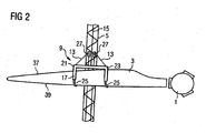
Figure 2 shows a section of the wind turbine lifting system ofFigure 1 in a viewing direction which is perpendicular to the viewing direction ofFigure 1 . -
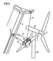
Figure 3 shows the mounting of a wind turbine blade to a rotor hub by the use of the of the inventive wind turbine blade lifting system shown inFigure 1 . -
Figure 4 shows an embodiment of the inventive wind turbine blade lifting system and the mounting of a wind turbine blade to a rotor hub by the use this embodiment. -
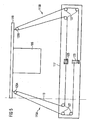
Figure 5 schematically shows the run of the control wire in the inventive wind turbine blade lifting system. - A first wind turbine blade lifting system will now be described with respect to
Figures 1 and2 . This system, which is not part of the invention itself, is suitable for performing the inventive method. WhileFigure 1 shows the lifting system in a view onto the tip of the lifted turbine blade,Figure 2 shows the upper part of the wind turbine blade lifting system in a plan view onto the blade's body. Also shown in both figures is the rotor hub 1 onto which theblade 3 is to be mounted. It is located at anacelle 33 at the top of atower 35. - The wind turbine blade lifting system comprises a
crane boom 5 which is mounted onto atruck 7, alifting device 9 which can be connected to thewind turbine blade 3, a winch arrangement comprising two individuallycontrollable winches 11, control wires 13 (only one control wire is visible inFigure 1 ) and abearing wire 15. - The holding
device 9 comprises aframe 17 andseats 19 on both ends 21, 23 of theframe 17 to which thewind turbine blade 3 is pressed by belts or straps 25. In addition, thebearing wire 15 is fixed to a central area of theframe 17 and thecontrol wires 13 are fixed to theframe 17 at itsends - The control wires run via
pulleys 27 which are located at theboom 5 to thewinches 11 of the winch arrangement. Both winches 11 of the winch arrangement are located at thebottom end 6 of theboom 5 and can be controlled individually so as to tension or loosen bothcontrol wires 13 individually. Thepulleys 27 are mounted onto a slidingcarriage 29 which can be moved along theboom 5. - The
bearing wire 15 is connected to afurther winch 31 which is operated for lifting thelifting device 9 with theblade 3 fixed thereto. In contrast thereto, thecontrol wires 13 have no substantial bearing function. - Lifting a
wind turbine blade 3 and mounting it to the rotor hub of a wind turbine will now be described with respect toFigures 1 ,2 and3 . The method comprises the steps of: i) lifting a wind turbine hub 1 to thenacelle 33 of a wind turbine with a lifting system and mounting the hub 1 on thenacelle 33, or lifting the wind turbine hub 1 and thenacelle 33 together with the lifting system and mounting thenacelle 33 including the hub 1 on awind turbine tower 35; ii) lifting at least onewind turbine blade 3 with a lifting system for handling thewind turbine blades 3, lifting said at least onewind turbine blade 3 into a substantially horizontal position; iii) controlling the orientation of said at least onewind turbine blade 3 in the substantially horizontal position when it has been lifted off the ground, usingcontrol wires 13 connecting the lifting system to thecrane boom 5, and iv) fixing said at least onewind turbine blade 3 in a substantially horizontal position to the wind turbine hub 1. - Hereby, it is possible to handle and mount a
wind turbine blade 3 in an advantageous manner. - In one implementation of the lifting system, a
control wire 13 is attached at eachend lifting frame 9, as has been described with respect toFigures 1 and2 . The twocontrol wires 13 run to thecrane boom 5 and from there over apulley 27 to twohydraulic winches 11 fitted to thecrane boom 5 at its bottom end. The twohydraulic winches 11 can be controlled independently. - In another implementation of the lifting system the
boom control wires 13 are kept automatically pre-tensioned during the lifting process so that control is maintained even though the distance from thepulleys 27 on thecrane boom 5 to thelifting device 9 is changed during the hoisting of thelifting device 9. This is accomplished by having one hydraulic winch that automatically maintains wire tension and another hydraulic winch that regulates the horizontal orientation and is controlled manually. - The different steps of the method will now be described in more detail.
- In a first step, the wind turbine rotor hub 1 is mounted to the
nacelle 33 of a wind turbine in a conventional manner by using thecrane boom 5. Alternatively, the rotor hub 1 could be mounted to thenacelle 33 on the ground and the nacelle together with the rotor hub 1 mounted thereto would then be mounted to the top of thetower 35 by using thecrane boom 5. As mounting thenacelle 33 onto the tower top and mounting the rotor hub 1 to thenacelle 33 are conventional steps they are not depicted in the figures. - In the next step, the
lifting device 9 is mounted onto awind turbine blade 3 which rests on the ground with itsdownstream edge 37 showing upwards. For mounting thelifting device 9 theframe 17 is lowered onto therotor blade 3 so that theseats 19 are set onto thedownstream section 37 of theblade 3. Then, thebelts 25 are wound around theupstream edge 39 of theblade 3, fixed to theframe 17 and tensioned so as to press theblade 3 to theseat 19. - After the
lifting device 9 has been mounted onto theblade 3 and theblade 3 has been secured to thelifting device 9 they are both lifted together by coiling thebearing wire 15 with thesecond winch 31. At the same time, thecontrol wires 13 are tensioned so as to drag thelifting device 9 with theblade 3 mounted therein towards thecrane boom 5. During lifting, the sliding carriage with thepulleys 27 follows theblade 3 on its way upwards where it is located slightly below thelifting device 9. By this measure the length of the control wires between thepulleys 27 and theframe 17 of thelifting device 9 can be kept low and almost constant during the whole lifting process. - By locating the
pulleys 27 below theframe 17 the tensioning force of the control wires act in a direction that includes an angle α to the lifting force exerted by thebearing wire 15. In the present embodiment, as shown inFigure 1 , the angle α is about 120°. Therefore, the tensioning forces exerted by thecontrol wires 13 have substantial components in the direction opposite the lifting force exerted by thebearing wire 15. By this configuration the blade's position can be securely stabilised. At the same time the components acting perpendicular to the lifting force are still large enough for suitably controlling the horizontal orientation of theblade 3. The ratio of the tensioning force components which act in the opposite direction to the lifting force to those components which act perpendicular to the lifting force can be set by the position of the slidingcarriage 29 relative to thelifting device 9. The lower the slidingcarriage 29 is with respect to thelifting device 9 the higher the component of the tensioning force is that acts in the opposite direction to the lifting force as compared to the component acting in a perpendicular direction to the lifting force. - By differently pre-tensioning the control wires, the horizontal orientation of the
turbine blade 3 can be varied. Varying the pre-tension of the control wires can either be done directly at the winches, for instance by personnel located at thewinches 11, or remotely by the crane operator which would offer the advantage that all control actions for positioning the blade relative to the rotor hub 1 can be performed by the same person. Positioning thewind turbine blade 3 relative to the rotor hub 1 for mounting theblade 3 to the hub 1 is schematically shown inFigure 3 . - Although pre-tensioning the
control wires 13 and controlling the horizontal orientation of thewind turbine blade 3 is performed by controlling bothwinches 11 of the winch arrangement individually it would also be possible to provide a winch which is acting on both control wires so as to always exert the same tensioning force on bothcontrol wires 13 while a second winch is used for regulating the horizontal orientation of the windturbine rotor blade 3. This would offer the advantage that only one winch needs to be controlled In order to control the horizontal position of theblade 3. However, this simplification of controlling the horizontal position of theblade 3 has to be paid for by a more complex construction of the winch arrangement. - After the
wind turbine blade 3 has been precisely oriented for mounting it to the rotor hub 1 personnel at the rotor hub fix theblade 3 to the hub and then thelifting device 9 is dismantled from therotor blade 3. - Although in the described lifting system the pulleys are mounted on a sliding
carriage 29 which can move along theboom 5 the pulleys can also be located at theboom 5 at a fixed position. In this case the ratio of the tensioning force components acting in the direction opposite the lifting force to the components acting perpendicular to the lifting force varies during the lifting process. However, this can be accounted for by suitably pre-tensioning thecontrol wires 13 during the lifting process. - An embodiment of the inventive wind turbine blade lifting system will now be described with respect to
figures 4 and5 .Figure 4 shows the embodiment in a perspective view similar to the view shown infigure 3 . Elements which do not differ from those in the lifting system described with respect toFigures 1 to 3 and which are not necessary for understanding the embodiment of the inventive wind turbine blade lifting system have been omitted from the figure for clarity reasons. Elements that have been omitted although present also in the embodiment of the inventive wind turbine blade lifting system are, for example, theseats 19 and thebelts 25 of alifting device 9. - The embodiment of the inventive wind turbine blade lifting device differs from the lifting system described with respect to
Figures 1 to 3 in that thecontrol wire 113 is not directly connected to thecrane boom 105 but is connected to thecrane boom 105 indirectly via guidingropes crane boom 105 of the second embodiment comprises atraverse beam 119 mounted to a top section of thecrane boom 105 from which tensioned guidingropes crane boom 105. The guidingropes - A
single control wire 113 is used for controlling the orientation of the lifting device 109 - and thereby the orientation of a blade mounted to the lifting device - within a horizontal plane. The control wire is subdivided into afirst branch 113A and asecond branch 113B where each branch comprises a section of the free length of thecontrol wire 113. Both ends of thecontrol wire 113 are connected to a spool of awinch 123, and both ends of the control wire can be wound up or off the spool of the winch so as to shorten or lengthen the free length of thecontrol wire 113, respectively, by turning the spool. Although both ends are connected to asingle winch 123 two individual winches, one for each end of thecontrol wire 113 could be present as well. However, using a single winch has the advantage that the length of the control wire can be controlled by only controlling a single winch. - An intermediate section of the
control wire 113 is wound around the spool of asecond winch 125. The intermediate section resembles a transition section between thefirst branch 113A and thesecond branch 113B. By turning the spool of second winch a length of the control wire can be transferred from one branch to the other. - The configuration of the winch arrangement comprising the
winches control wire 113 is depicted schematically infigure 5 . The figure shows a top view onto theframe 117, thecrane boom 105 and thetraverse beam 119. Thecontrol wire 113, which is fixed with both of its ends to the spool offirst winch 123, runs via twodeflection pulleys 127 to a pulley arrangement comprising afirst pulley 129A and asecond pulley 131A (the whole pulley arrangement can be seen infigure 4 ) and from there back to adeflection pulley 127 and to the spool of thesecond winch 125. Thecontrol wire 113 is not fixed to the spool ofsecond winch 125 but wrapped one or more times around it. The section of thecontrol wire 113 that runs from thefirst winch 123 via thepulley arrangement second winch 125 forms thefirst branch 113A of the control wire's free length. From thesecond winch 125 of the winch arrangement the control wire runs via a further deflection pulley to apulley 129B of a pulley arrangement located between thecontrol wire 113 and thesecond guiding rope 121B and from there via further deflection pulleys 127 back to the spool of thefirst winch 123 to which the second end of thecontrol wire 113 is also fixed. - As can be seen in
figure 5 , winding the control wire ends up the spool of thefirst winch 123 will drag theframe 117, to which the winch arrangement is fixed, towards thecrane boom 105. On the other hand, winding the ends of thecontrol wire 113 off thewinch 123 will allow theframe 117 to move away from thecrane boom 105. Furthermore, rotating the spool of thesecond winch 125 will transfer free length from one of thebranches frame 117 within a horizontal plane, for example relative to thetraverse 119, can be changed by controlling thesecond winch 125. Infigure 5 the long side of theframe 117 runs more or less parallel to thetraverse 119. If now the spool ofsecond winch 125 would be rotated such that free length of thecontrol wire 113 is transferred from thefirst branch 113A to thesecond branch 113B the first branch end of theframe 117 would move towards thepulley 129A while the second branch end of theframe 117 would move away from thepulley 129B. As a consequence, the first branch end would turn towards the guidingrope 121A while the other end would move away from therespective guiding rope 121B. On the other hand, rotating the spool of thefirst winch 123 would move theframe 117 towards or away from the guidingropes frame 117 within the horizontal plane. - As already mentioned, both
branches control wire 113 are connected to arespective guiding rope 121A, 121b viapulley arrangements branches respective guiding ropes bearing wire 115. Note that in difference to the lifting system described with respect toFigures 1 to 3 the bearing wire comprises four branches each of which is connected to a corner of theframe 117. However the bearing wire of the lifting system described with respect toFigures 1 to 3 could also be used in the embodiment of the inventive wind turbine blade lifting system and vice versa. - In the embodiment of the wind turbine blade lifting system the distance of the blade from the
crane boom 105 as well as the orientation of the blade within the horizontal plane can be controlled independent of reach other by independently controlling thewinches frame 117. The forces which are exerted by the winch arrangement and transferred to the pulley arrangements 129, 131 via thecontrol wire 113 will be transferred by the pulley arrangements to the guiding ropes 121. By the guidingropes ropes ropes traverse 119 and the winches at the crane boom's bottom end act substantially parallel to thecrane boom 105 which avoids loads acting perpendicular on thecrane boom 105. - Lifting a wind turbine rotor blade with the embodiment of the inventive wind turbine blade lifting system does not differ from lifting a turbine blade with the lifting system described with respect to
Figures 1 to 3 except for the way of controlling the orientation of theframe 117 and thereby the orientation of the blade within the horizontal plane and its distance from the crane boom. - The invention provides a possibility of controlling a wind turbine rotor blade's orientation in the substantially horizontal position when it has been lifted off the ground, using control wires connecting the lifting system to a crane boom. The feature of lifting the wind turbine blade in the same substantially horizontal orientation as it has when fitted to the lifting device when lying on the ground is advantageous as this eliminates any need for upturning the blade. The feature of controlling the orientation of the blade in the substantially horizontal position when it has been lifted off the ground, using control wires connecting the lifting system to the crane boom is advantageous as it eliminates the need for a group of persons stationed at ground level and seeking to control the orientation using long ropes. When installing the blade in accordance with the invention the crane operator can control both the lifting height and the blade orientation from one control position.
Claims (10)
- A method for mounting a wind turbine blade (3) to a wind turbine hub (1) by use of a crane boom (5, 105), wherein the orientation of the blade (3) is kept substantially horizontal when the blade (3) is lifted off the ground and mounted to the rotor hub (1),
wherein
at least one control wire (13, 113) and a winch arrangement (11, 123, 125) are used for controlling the orientation of the blade (3) in addition to at least one bearing wire (15, 115) for bearing the blade's weight,
characterised in that
a winch arrangement (123, 125) which is located at a lifting device (109) which is designed so as to be attachable to the wind turbine blade (3), and at least one control wire (113) which is controllable by the winch arrangement (123, 125) are used for controlling the distance of the blade (3) from the crane boom (105) and/or the orientation of the blade (3) within a horizontal plane. - The method according to claim 1,
characterised in that
a winch arrangement (123, 125) with at least a first winch (123) and a second winch (125) is used for controlling the at least one control wire (113) where the distance of the blade (3) from the crane boom (105) is controlled via the first winch (123) and the orientation of the blade (3) within the horizontal plane is controlled via the second winch (125). - The method according to claim 2,
characterised in that- a control wire (113) having a free length with at least a first branch (113A) comprising a first fraction of the control wire (113) and a second branch (113B) comprising a second fraction of the control wire (113) is used, both branches of the control wire being connected directly or indirectly to the crane boom (105),- the free length of the control wire (113) is controlled via the first winch (123), and- the distribution of the free length of the control wire (113) to the first fraction and the second fraction is controlled via the second winch (125). - A wind turbine blade lifting system comprising a lifting device (9, 109) with a frame (17, 117) which is designed so as to be connectable to a wind turbine blade (3), a crane boom (5, 105), a winch arrangement (11, 123, 125), and at least one control wire (13, 113) which runs to the winch arrangement (11, 123, 125) for controlling the blade's orientation to be substantially horizontal and/or for controlling the blade's (3) orientation within a substantially horizontal plane when it has been lifted off the ground.
characterised in that
the winch arrangement (123, 125) is located at the lifting device (109), and at least one rope (121A, 121B) extends from the top end of the boom (105) to its bottom end and in which the control wire (113) is connected to the at least one rope (121A, 121B). - The wind turbine blade lifting system as claimed in claim 4, in which
the at least one control wire (113) is connected to the at least one rope (121A, 121B) by means of pulleys (129A, 131A, 129B, 131B). - The wind turbine blade lifting system as claimed in any of the claims 4 to 5,- which comprises at least one control wire (113) having a free length with at least a first ranch (113A) comprising a first fraction of the control wire (113) and a second branch (113B) comprising a second fraction of the control wire (113) both branches of the control wire (113) being connected directly or indirectly to the crane boom (105), and- in which the winch arrangement (123, 125) comprises at least a first winch (123) and a second winch (125), where the first winch (123) is designed to act on the control wire (113) for controlling its free length and the second winch (125) is designed to act on the control wire (113) for controlling the distribution of the free length of the control wire (113) to the first fraction and the second fraction.
- The wind turbine blade lifting system as claimed in claim 6, in which
the control wire (113) comprises ends which are connected to the first winch (123) and an intermediate section which is wrapped around the second winch (125). - The wind turbine blade lifting system as claimed in claim 6 or claim 7, in which
a first rope (121A) and a second rope (121B) extend from the top end of the boom (105) to its bottom end and in which the first branch (113A) and the second branch (113B) of the control wire (113) are connected to the first rope (121A) and the second rope (121B), respectively. - The wind turbine blade lifting system as claimed in claim 8, in which
the first branch (113A) and the second branch (113B) of the control wire (113) are connected to the first rope (121A) and the second rope (121B), respectively, by means of pulleys (129A, 131A, 129B, 131B). - The wind turbine blade lifting system as claimed in any of the claims 4 to 9, wherein the at least one control wire (113) substantially runs within a horizontal plane.
Priority Applications (1)
| Application Number | Priority Date | Filing Date | Title |
|---|---|---|---|
| DK07856251.9T DK2084098T4 (en) | 2006-11-23 | 2007-11-23 | METHOD AND DEVICE FOR INSTALLATION OF WINDMILL LEVELS. |
Applications Claiming Priority (5)
| Application Number | Priority Date | Filing Date | Title |
|---|---|---|---|
| EP06024336 | 2006-11-23 | ||
| EP06024337 | 2006-11-23 | ||
| EP07013724A EP1925582B1 (en) | 2006-11-23 | 2007-07-12 | Method and a device for mounting of wind turbine blades |
| EP07013725.2A EP1925583B2 (en) | 2006-11-23 | 2007-07-12 | Method of handling wind turbine blades and device for mounting wind turbine blades, in particular mounting blades on a wind turbine |
| PCT/EP2007/010221 WO2008061797A1 (en) | 2006-11-23 | 2007-11-23 | Method and device for mounting of wind turbine blades |
Publications (3)
| Publication Number | Publication Date |
|---|---|
| EP2084098A1 EP2084098A1 (en) | 2009-08-05 |
| EP2084098B1 EP2084098B1 (en) | 2011-02-02 |
| EP2084098B2 true EP2084098B2 (en) | 2019-01-16 |
Family
ID=39315457
Family Applications (2)
| Application Number | Title | Priority Date | Filing Date |
|---|---|---|---|
| EP07013724A Active EP1925582B1 (en) | 2006-11-23 | 2007-07-12 | Method and a device for mounting of wind turbine blades |
| EP07856251.9A Active EP2084098B2 (en) | 2006-11-23 | 2007-11-23 | Method and device for mounting of wind turbine blades |
Family Applications Before (1)
| Application Number | Title | Priority Date | Filing Date |
|---|---|---|---|
| EP07013724A Active EP1925582B1 (en) | 2006-11-23 | 2007-07-12 | Method and a device for mounting of wind turbine blades |
Country Status (10)
| Country | Link |
|---|---|
| US (4) | US8191721B2 (en) |
| EP (2) | EP1925582B1 (en) |
| JP (1) | JP5420165B2 (en) |
| CN (2) | CN101230835B (en) |
| AT (1) | ATE497474T1 (en) |
| CA (1) | CA2611343C (en) |
| DE (1) | DE602007012362D1 (en) |
| DK (1) | DK2084098T4 (en) |
| ES (1) | ES2356024T5 (en) |
| WO (1) | WO2008061797A1 (en) |
Families Citing this family (161)
| Publication number | Priority date | Publication date | Assignee | Title |
|---|---|---|---|---|
| EP1925582B1 (en) * | 2006-11-23 | 2010-06-23 | Siemens Aktiengesellschaft | Method and a device for mounting of wind turbine blades |
| DK1925583T4 (en) * | 2006-11-23 | 2013-07-15 | Siemens Ag | Method for handling wind turbine blades and device for mounting wind turbine blades, especially mounting blades on a wind turbine |
| JP4885071B2 (en) * | 2007-06-19 | 2012-02-29 | 三菱重工業株式会社 | How to replace wind turbine equipment |
| JP4885073B2 (en) * | 2007-06-20 | 2012-02-29 | 三菱重工業株式会社 | Wind turbine rotor blade suspension device, wind turbine rotor blade attachment method, and wind turbine generator construction method |
| WO2009100377A1 (en) * | 2008-02-07 | 2009-08-13 | Wind Innovatins Ip, Llc | Rotor hub maintenance system |
| DE202008016578U1 (en) * | 2008-12-15 | 2011-04-07 | Liebherr-Werk Ehingen Gmbh | Manipulator for mounting rotor blades of a wind turbine |
| CA2760231A1 (en) * | 2009-04-29 | 2010-11-04 | Siemens Aktiengesellschaft | Blade lifting system with saloon doors |
| WO2010133228A2 (en) * | 2009-05-18 | 2010-11-25 | Vestas Wind Systems A/S | A hub for a wind turbine |
| FR2946700B1 (en) | 2009-06-15 | 2018-07-20 | Soletanche Freyssinet | METHOD, SYSTEM AND DEVICE FOR CONTRIBUTING TO THE ASSEMBLY OF A WINDMILL. |
| US20100143136A1 (en) * | 2009-08-31 | 2010-06-10 | Jeffrey Michael Daniels | Systems and methods for assembling a pitch assembly for use in a wind turbine |
| US8496423B2 (en) * | 2009-09-10 | 2013-07-30 | National Oilwell Varco, L.P. | Windmill conveyance system and method for using same |
| US8443571B2 (en) * | 2009-09-19 | 2013-05-21 | Btpatent Llc | Wind power equipment and assembly |
| US8070000B2 (en) | 2009-10-23 | 2011-12-06 | Vestas Wind Systems A/S | Apparatus and method for assembling wind turbines |
| DE102009058268A1 (en) | 2009-12-14 | 2011-06-16 | Liebherr-Werk Ehingen Gmbh | Crane e.g. crawler crane, has hoist rope guided over arm and including control cables that are provided with control ropes, where control ropes are directly attached to load i.e. rotor |
| ES2393604T3 (en) * | 2010-01-14 | 2012-12-26 | Siemens Aktiengesellschaft | Clamping device to hold a blade for a wind turbine and method of insalation of wind turbine blades |
| DK177006B1 (en) | 2010-01-19 | 2010-11-22 | Ah Ind Projects Aps | Method for controlling orientation of a load suspended in a carrier wire around the wire as well as a player arrangement |
| JP4547039B1 (en) * | 2010-02-23 | 2010-09-22 | 株式会社日本製鋼所 | Installation method of rotor blade for wind power generation |
| DE202010003269U1 (en) * | 2010-03-08 | 2011-08-23 | Liebherr-Werk Ehingen Gmbh | crane |
| DE202010015616U1 (en) * | 2010-11-18 | 2012-03-01 | Liebherr-Werk Ehingen Gmbh | crane |
| US8944262B2 (en) * | 2010-03-08 | 2015-02-03 | Liebherr-Werk Ehingen Gmbh | Load hook control device for a crane |
| DE202010012237U1 (en) | 2010-09-06 | 2011-12-08 | Liebherr-Werk Ehingen Gmbh | crane |
| EP2369174B1 (en) * | 2010-03-09 | 2012-11-28 | Lm Glasfiber A/S | A method of craneless mounting or demounting of a wind turbine blade |
| CN102192111B (en) * | 2010-03-11 | 2012-11-07 | 中交上海三航科学研究院有限公司 | Installation method of blades of offshore wind turbine |
| US20110221215A1 (en) * | 2010-03-12 | 2011-09-15 | Vestas Wind Systems A/S | Methods and apparatus for handling a tower section of a wind turbine with a crane |
| DE202010004093U1 (en) * | 2010-03-23 | 2011-05-05 | Wobben, Aloys, Dipl.-Ing. | Lifting unit for lifting a rotor of a wind energy plant |
| CA2735863A1 (en) | 2010-05-31 | 2011-11-30 | Mitsubishi Heavy Industries, Ltd. | A blade end portion protecting bag and a rotor installing method for a wind turbine |
| CN101871425B (en) * | 2010-06-22 | 2012-08-08 | 沈阳瑞祥风能设备有限公司 | Control system and method for installing and adjusting blades of aerogenerator |
| ES1073014Y (en) | 2010-07-29 | 2011-03-01 | Acciona Windpower Sa | UIL FOR ELEVATION AND DESCENT OF A WINDER SHOVEL |
| US9719487B2 (en) * | 2010-09-15 | 2017-08-01 | Vestas Wind Systems A/S | Wind turbine blade structures, lifting assemblies and methods of blade handling |
| DK2434142T3 (en) | 2010-09-27 | 2013-06-24 | Siemens Ag | Method, unit and system for mounting wind turbine blades on a wind turbine hub |
| EP2532890A4 (en) | 2011-04-05 | 2013-06-19 | Mitsubishi Heavy Ind Ltd | Regenerated energy electricity generation device |
| US9261072B2 (en) * | 2011-05-11 | 2016-02-16 | Daniel E. Davis | Wind turbine elevator for hoisting a naecelle along a tower and pivoting the naecelle at a top of the tower |
| WO2012163358A1 (en) | 2011-05-27 | 2012-12-06 | Vestas Wind Systems A/S | Apparatus for manipulating a wind turbine blade and method of blade handling |
| EP2532879B1 (en) | 2011-06-07 | 2014-03-19 | Siemens Aktiengesellschaft | Assembly and/or maintenance of a wind turbine |
| DE102011116189B3 (en) * | 2011-06-21 | 2012-10-04 | Repower Systems Se | Load handling device for raising rotor blade of wind energy plant to mounting position, has support assembly having supporting surface projected in vertical plane to make contact of rotor blade or attaching element with support assembly |
| EP2538073B1 (en) | 2011-06-24 | 2016-04-13 | Vestas Wind Systems A/S | An improvement for horizontal blade installation for wind turbines |
| US20120027611A1 (en) * | 2011-07-07 | 2012-02-02 | General Electric Company | Compression member for wind turbine rotor blades |
| AU2011338137A1 (en) | 2011-08-10 | 2013-02-28 | Mitsubishi Heavy Industries, Ltd. | Renewable energy type electric power generation device. |
| US8360398B2 (en) | 2011-08-17 | 2013-01-29 | General Electric Company | Device for handling a wind turbine rotor blade and a method for handling wind turbine rotor blades |
| US8595931B2 (en) | 2011-08-22 | 2013-12-03 | General Electric Company | Lift system and method for constructing a wind turbine |
| FR2979335B1 (en) * | 2011-08-22 | 2015-11-13 | Degremont | DEVICE FOR HANDLING AN EXTENDED OBJECT, IN PARTICULAR A MEMBRANE FILTRATION MODULE, AND HANDLING METHOD USING THE DEVICE |
| ES2399014B1 (en) * | 2011-09-07 | 2014-05-21 | Matis Hispania, S. A. | TOOL FOR LIFTING A WINDER BLADE |
| WO2013042250A1 (en) | 2011-09-22 | 2013-03-28 | 三菱重工業株式会社 | Rotor-blade attachment method for renewable energy power generation device |
| IN2012DN03062A (en) | 2011-09-22 | 2015-07-31 | Mitsubishi Heavy Ind Ltd | |
| DK2589795T3 (en) | 2011-11-04 | 2015-03-30 | Siemens Ag | Lifting frame for lifting a wind turbine rotor blade and the method of mounting vindmøllerotorvinger |
| DE102011121438A1 (en) * | 2011-12-16 | 2013-06-20 | Robert Bosch Gmbh | Device for holding housing of planetary gear box in e.g. wind energy plant, has adapters arranged at opposite sides of component and fastenable in region of center of gravity plane through component, where carriers co-operate with adapters |
| CN103174601B (en) * | 2011-12-22 | 2015-05-27 | 华锐风电科技(集团)股份有限公司 | Fan blade protective sleeve |
| DE102012201088A1 (en) * | 2012-01-25 | 2013-07-25 | Wobben Properties Gmbh | Method and device for mounting a rotor hub of a wind energy plant |
| DK2623768T3 (en) * | 2012-02-03 | 2014-09-01 | Siemens Ag | Lifting frame for lifting a wind turbine rotor blade, method for mounting a wind turbine rotor blade for a wind turbine rotor hub and method for assembling a wind turbine rotor |
| CN103423105B (en) * | 2012-05-21 | 2015-11-25 | 华锐风电科技(集团)股份有限公司 | A kind of impeller of wind turbine set assembling device and impeller assembling method |
| DK2669238T3 (en) | 2012-06-01 | 2017-03-13 | Siemens Ag | Easier handling of wind turbine blades |
| KR101346176B1 (en) * | 2012-06-22 | 2013-12-31 | 삼성중공업 주식회사 | Assembly robot for windmill blade |
| KR101346180B1 (en) * | 2012-06-26 | 2013-12-31 | 삼성중공업 주식회사 | Blade installing system for wind turbine |
| KR101323800B1 (en) | 2012-06-28 | 2013-10-31 | 삼성중공업 주식회사 | Assembly robot for windmill blade |
| GB201214656D0 (en) * | 2012-08-16 | 2012-10-03 | W3G Shipping Ltd | Offshore structures and associated apparatus and method |
| SG11201501476YA (en) * | 2012-08-30 | 2015-05-28 | High Wind N V | Device and method for assembling a structure |
| US9950910B2 (en) | 2012-09-11 | 2018-04-24 | Eltronic A/S | Method for controlling the orientation of a load suspended from a bearing wire about said bearing wire and a winch arrangement |
| EP2708734B1 (en) * | 2012-09-13 | 2016-11-09 | ALSTOM Renewable Technologies | Wind turbine blade and methods for transporting, storing and installing wind turbine blades |
| CN102852722B (en) * | 2012-09-27 | 2014-09-17 | 北京金风科创风电设备有限公司 | Hub displacement device and lifting method for impellers in direct-driven wind generating set |
| KR101401985B1 (en) * | 2012-09-28 | 2014-05-30 | (주)살코 | Floating crane with jack-up system for floating structure |
| DE102012109403B3 (en) * | 2012-10-02 | 2014-03-06 | Repower Systems Se | Method for mounting a rotor blade and mounting arrangement |
| DK177672B1 (en) * | 2012-11-27 | 2014-02-17 | Liftra Ip Aps | Lifting Frame |
| WO2014097254A1 (en) * | 2012-12-20 | 2014-06-26 | High Wind N.V. | Device and method for placing a structural component |
| CN104968597B (en) * | 2012-12-20 | 2017-07-11 | 疾风有限公司 | For the apparatus and method of the component of displacement structure |
| BE1021593B1 (en) * | 2012-12-20 | 2015-12-16 | High Wind Nv | DEVICE AND METHOD FOR POSING A BUILDING PART |
| KR101400203B1 (en) * | 2013-01-29 | 2014-05-27 | 삼성중공업 주식회사 | Balancing device and method for mounting wind turbine blade using the same |
| US10322913B2 (en) | 2013-02-18 | 2019-06-18 | High Wind N.V. | Device and method for placing a rotor blade of a wind turbine |
| BE1021796B1 (en) * | 2013-02-18 | 2016-01-18 | High Wind N.V. | DEVICE AND METHOD FOR PLACING AT SEA A ROTOR SHEET OF A WIND TURBINE |
| US9321616B2 (en) * | 2013-03-14 | 2016-04-26 | Marvin M. May | Lifting systems |
| US9145867B2 (en) * | 2013-03-14 | 2015-09-29 | General Electric Company | System and method for installing a blade insert between separate portions of a wind turbine rotor blade |
| DE102013205030B4 (en) * | 2013-03-21 | 2015-10-22 | Senvion Gmbh | System and method for transporting and testing a crane for use in an offshore wind turbine |
| KR101484121B1 (en) * | 2013-03-29 | 2015-01-21 | 곽대진 | Floating Crane for Installation Offshore Wind Tower |
| CN103277269A (en) * | 2013-05-17 | 2013-09-04 | 江苏金风科技有限公司 | Method and device for rotation of blades of wind generating set |
| DE102013211751A1 (en) * | 2013-06-21 | 2014-12-24 | Wobben Properties Gmbh | Method for mounting a wind turbine rotor blade and wind turbine rotor blade |
| DE102014207712A1 (en) * | 2013-06-24 | 2014-12-24 | Siemens Aktiengesellschaft | Apparatus and method for rotating a rotor of a wind turbine |
| DE102014003906A1 (en) * | 2013-07-01 | 2015-01-08 | Liebherr-Werk Biberach Gmbh | Tower Crane |
| DE202013006584U1 (en) * | 2013-07-22 | 2014-10-23 | Liebherr-Werk Ehingen Gmbh | Ballast device for generating a winch bias |
| DK2832675T3 (en) * | 2013-07-29 | 2018-10-22 | Siemens Ag | Wing gripper |
| EP2832677B1 (en) * | 2013-07-29 | 2016-05-25 | Siemens Aktiengesellschaft | Blade gripping tool and device |
| US20150028608A1 (en) * | 2013-07-29 | 2015-01-29 | General Electric Company | Method and apparatus for handling a rotor blade |
| US9429138B2 (en) * | 2013-08-09 | 2016-08-30 | Gamesa Innovation & Technology, S.L. | Apparatus, system and method for wind turbine component replacement |
| DK2837819T3 (en) * | 2013-08-14 | 2016-05-02 | Siemens Ag | Method of mounting a rotor blade |
| DE102013110464A1 (en) | 2013-09-23 | 2015-03-26 | Max Bögl Wind AG | Device and method for handling, assembly or disassembly of components of a wind turbine |
| BE1021044B1 (en) * | 2013-11-06 | 2015-02-25 | Dufour Sa | DEVICE AND METHOD FOR TURNING THE LIFTING CABLE OF A CRANE VIA ITS HOOK BY ROLLING THE CABLE ON THE CRANE LIFTING WINCH |
| WO2015084173A1 (en) | 2013-12-05 | 2015-06-11 | Xemc Darwind B.V. | A method of handling a direct drive wind turbine blade; and a direct drive wind turbine assembly |
| EP2889251B1 (en) * | 2013-12-30 | 2016-08-24 | Siemens Aktiengesellschaft | Load guiding arrangement |
| EP2924278B1 (en) | 2014-03-26 | 2018-08-08 | Areva Wind GmbH | Tool for handling a long and heavy object |
| WO2015165463A1 (en) | 2014-04-28 | 2015-11-05 | Liftra Ip Aps | Method and device for automatic control of the position of a burden suspended in a main wire on a crane |
| DK178141B1 (en) * | 2014-06-03 | 2015-06-22 | Envision Energy | Wind turbine blade lifting device and a method for lifting a wind turbine blade |
| DE102015006992B4 (en) * | 2014-06-10 | 2021-04-15 | Liebherr-Werk Ehingen Gmbh | Method and system for calculating data for the operation of a crane |
| DK178406B1 (en) * | 2014-06-12 | 2016-02-08 | Envision Energy Denmark Aps | Lifting device for rotor assembly and method thereof |
| US9651021B2 (en) | 2014-09-09 | 2017-05-16 | General Electric Company | System and method for removing and/or installing a rotor blade of a wind turbine |
| PT3020622T (en) * | 2014-11-11 | 2017-09-11 | Seasight Davits Aps | System and lifting unit for lifting loads of varying weight |
| KR101657224B1 (en) * | 2015-02-09 | 2016-09-13 | 박병룡 | Floating Crane for Installation Offshore Wind Tower |
| EP3250494B1 (en) * | 2015-03-18 | 2018-12-19 | Siemens Aktiengesellschaft | Automated receptor system |
| EP3070044B1 (en) * | 2015-03-19 | 2018-08-08 | ALSTOM Renewable Technologies | Hoisting systems and methods |
| US9650840B2 (en) | 2015-04-27 | 2017-05-16 | National Oilwell Varco, L.P. | Method and apparatus for erecting a drilling rig |
| US9890022B2 (en) | 2015-05-07 | 2018-02-13 | General Electric Company | Method for suspending a rotor blade from a hub of a wind turbine |
| US9821417B2 (en) | 2015-05-07 | 2017-11-21 | General Electric Company | System and method for replacing a pitch bearing |
| DE102015006778A1 (en) | 2015-06-01 | 2016-12-01 | Senvion Gmbh | System and method for transporting and lifting a rotor blade of a wind energy plant |
| US10287940B2 (en) | 2015-08-06 | 2019-05-14 | Clean Air-Engineering—Maritime, Inc. | Movable emission control system for auxiliary diesel engines |
| US10422260B2 (en) * | 2015-08-06 | 2019-09-24 | Clean Air-Engineering-Maritime, Inc. | Movable emission control system for auxiliary diesel engines |
| DE102015115146A1 (en) * | 2015-09-09 | 2017-03-09 | Bauer Maschinen Gmbh | Construction machine and method for moving up and down a lifting element |
| EP3356278B2 (en) * | 2015-10-01 | 2023-11-08 | Vestas Wind Systems A/S | A lifting arrangement for lifting a wind turbine component |
| JP6769700B2 (en) * | 2015-10-19 | 2020-10-14 | 三菱航空機株式会社 | Aircraft landing gear handling dolly and how to install and remove the landing gear using it |
| US10066601B2 (en) | 2015-10-22 | 2018-09-04 | General Electric Company | System and method for manufacturing wind turbine rotor blades for simplified installation and removal |
| EP3394431B1 (en) * | 2015-12-22 | 2020-11-11 | Vestas Wind Systems A/S | A method and a system for mounting a rotor to a drive shaft of a wind turbine |
| GB201603545D0 (en) * | 2016-03-01 | 2016-04-13 | Vestas Wind Sys As | Method and apparatus for weighing an elongate object |
| CN105692448B (en) * | 2016-04-12 | 2018-07-20 | 南通润邦重机有限公司 | A kind of steady goods system of adjustable-angle crane |
| US10906785B2 (en) | 2016-06-15 | 2021-02-02 | Itrec B.V. | Crane for wind turbine blade assembly, a vessel, a hoisting method, and an assembly method |
| DE102016111514A1 (en) * | 2016-06-23 | 2017-12-28 | Wobben Properties Gmbh | Method for erecting a wind energy plant and lifting traverse for mounting a rotor blade of a wind energy plant |
| CN105947890B8 (en) * | 2016-06-24 | 2017-12-22 | 成都世唯科技有限公司 | A kind of deflection mechanism of wind-driven generator leaf suspender |
| WO2018072927A1 (en) | 2016-10-20 | 2018-04-26 | Siemens Aktiengesellschaft | Lifting device and method for wind turbine components |
| CN106315408B (en) * | 2016-10-21 | 2017-11-28 | 成都世唯科技有限公司 | A kind of fan blade assembles and disassembles aerial statue adjusting device |
| DK3507230T3 (en) * | 2016-11-03 | 2023-08-07 | Siemens Gamesa Renewable Energy As | LIFTING DEVICE FOR WIND TURBINE COMPONENTS |
| CN110199116B (en) * | 2016-12-21 | 2021-05-07 | 维斯塔斯风力系统有限公司 | Wind turbine repair or construction method and apparatus |
| US11268490B2 (en) | 2016-12-23 | 2022-03-08 | Vestas Wind Systems A/S | Method and an assembly for handling wind turbine blades |
| ES2865455T3 (en) * | 2016-12-23 | 2021-10-15 | Vestas Wind Sys As | A method and set for handling wind turbine blades |
| CN110199117B (en) * | 2016-12-28 | 2020-12-29 | 维斯塔斯风力系统有限公司 | Method and system for lifting a wind turbine rotor |
| DE202017100494U1 (en) * | 2017-01-30 | 2018-05-03 | Ematec Manfred Eberhard Maschinen- Und Greiftechnik E.K. | Device for controlled movement of a load and crane arrangement |
| JP6504732B2 (en) * | 2017-02-27 | 2019-04-24 | 株式会社クラフトワークス | Apparatus, system and method for performing maintenance of an object |
| CN106865415A (en) * | 2017-03-30 | 2017-06-20 | 中国矿业大学 | It is a kind of to restrain large-scale general lifting stabilising arrangement and method that weight swings and rotates |
| DE102017206349B4 (en) | 2017-04-12 | 2019-04-11 | Siemens Gamesa Renewable Energy A/S | Weighing device for a wind turbine rotor blade |
| ES2870228T3 (en) | 2017-04-18 | 2021-10-26 | Siemens Gamesa Renewable Energy As | Procedure to install or uninstall a component of a wind turbine |
| CN107178456B (en) * | 2017-05-16 | 2019-05-17 | 哈尔滨工程大学 | A kind of horizontal-shaft tidal generation blading offshore installation method |
| CN110709602B (en) * | 2017-06-12 | 2022-04-15 | 西门子歌美飒可再生能源公司 | Offshore wind turbine installation |
| IT201700068019A1 (en) * | 2017-06-19 | 2018-12-19 | Saipem Spa | STABILIZER FRAME, SYSTEM AND METHOD FOR INSTALLING A WIND GENERATOR ON AN OFFSHORE SUPPORT STRUCTURE |
| US10508645B2 (en) | 2017-07-17 | 2019-12-17 | General Electric Company | System and method for suspending a rotor blade of a wind turbine uptower |
| PL3470198T3 (en) | 2017-10-11 | 2024-04-22 | Nordex Energy Se & Co. Kg | Method for producing a rotor blade spar cap for a rotor blade of a wind turbine and system for producing a rotor blade spar cap |
| PL3724120T3 (en) | 2017-12-13 | 2023-06-19 | Enabl A/S | System, device and method for lifting and controlling the horizontal orientation and/or position of components |
| NL2020389B1 (en) | 2018-02-06 | 2019-08-14 | Itrec Bv | A crane |
| EP3787871B1 (en) * | 2018-04-30 | 2023-08-16 | General Electric Company | Methods for manufacturing wind turbine rotor blades and components thereof |
| EP4276305A3 (en) | 2018-05-17 | 2024-01-17 | Vestas Wind Systems A/S | Wind turbine element lifting method and apparatus |
| JP7151236B2 (en) * | 2018-07-20 | 2022-10-12 | 株式会社大林組 | Blade mounting device |
| EP3830411B1 (en) * | 2018-07-27 | 2023-03-15 | Vestas Wind Systems A/S | Method of installing a rotor on a wind turbine, a rotor hub and counterweight assembly |
| DK180504B1 (en) * | 2018-09-13 | 2021-06-03 | Liftra Ip Aps | Rotor blade hoisting system and method for mounting and / or removing a rotor blade |
| CN113454017B (en) * | 2018-12-28 | 2023-07-07 | 维斯塔斯风力系统有限公司 | Method for handling wind turbine components with a control device |
| EP3902763A1 (en) * | 2018-12-28 | 2021-11-03 | Vestas Wind Systems A/S | A lifting assembly and a method for handling a component |
| JP7238531B2 (en) * | 2019-03-26 | 2023-03-14 | 株式会社タダノ | crane |
| DK180819B1 (en) * | 2019-04-02 | 2022-04-28 | Liftra Ip Aps | Method for mounting a self-lifting crane on a wind turbine and self-lifting crane |
| DK180872B1 (en) * | 2019-05-02 | 2022-06-08 | Liftra Ip Aps | Self-hoisting crane system and method for hoisting a self-hoisting crane |
| US12037979B2 (en) * | 2019-06-11 | 2024-07-16 | Vestas Wind Systems A/S | Method for handling a wind turbine component and associated lifting system |
| CN110329939B (en) * | 2019-07-19 | 2021-01-26 | 燕山大学 | Impeller hoist and mount auxiliary docking device |
| DK180448B1 (en) | 2019-09-11 | 2021-04-28 | Eltronic As | A load guiding arrangement arranged for mounting to a crane |
| CN110654987B (en) * | 2019-09-29 | 2020-07-24 | 大连理工大学 | Crane extension installing device for realizing bidirectional resultant force control and method for controlling crane through bidirectional tension |
| CN111170174B (en) * | 2019-12-12 | 2021-06-08 | 江苏鹤钢重工有限公司 | Hoisting and transporting equipment for wind power generation blades |
| BE1028262B1 (en) | 2020-05-04 | 2021-12-07 | Deme Offshore Be Nv | Lifting system and method for lifting an elongated object |
| CN111943060B (en) * | 2020-08-17 | 2022-03-18 | 交通运输部公路科学研究所 | Posture adjusting method |
| EP3957593B1 (en) * | 2020-08-19 | 2024-10-09 | Siemens Gamesa Renewable Energy A/S | Lifting apparatus for a lifting crane |
| CN112027909A (en) * | 2020-08-25 | 2020-12-04 | 广东工业大学 | Hoisting control method and device for preventing rotation and swinging of offshore giant blade |
| CN112174013B (en) * | 2020-09-28 | 2022-03-01 | 中天科技集团海洋工程有限公司 | Carrying device for impeller and carrying method thereof |
| EP4027007A1 (en) * | 2021-01-12 | 2022-07-13 | General Electric Renovables España S.L. | Method of mounting blades to a rotor hub of a wind turbine |
| EP4080039A1 (en) * | 2021-04-19 | 2022-10-26 | Siemens Gamesa Renewable Energy A/S | Wind turbine blade and wind turbine |
| CN114248875B (en) * | 2022-01-07 | 2022-12-06 | 烟台大学 | Ocean scientific investigation equipment prevents swinging recovery unit |
| JP7480817B2 (en) | 2022-10-14 | 2024-05-10 | 株式会社大林組 | Rotating body installation method and blade lift-up device |
| WO2024083833A1 (en) | 2022-10-19 | 2024-04-25 | Itrec B.V. | Crane having a crane boom provided with a tagline system |
| NL2033359B1 (en) | 2022-10-19 | 2024-05-06 | Itrec Bv | Crane having a crane boom provided with a tagline system |
| CN115366046B (en) * | 2022-10-27 | 2023-01-31 | 新乡西玛鼓风机股份有限公司 | Shaft dismounting device for boiler fan impeller |
| CN116281603B (en) * | 2023-05-16 | 2023-07-21 | 河北倚天建筑科技有限公司 | Wallboard hoisting device for mounting prefabricated structure |
| CN117755950A (en) * | 2023-09-11 | 2024-03-26 | 三峡物资招标管理有限公司 | Super-long fan blade hoisting method |
| CN117142353B (en) * | 2023-10-31 | 2024-01-09 | 大连华锐重工集团股份有限公司 | Full-automatic overturn control method for nuclear island main equipment |
Citations (4)
| Publication number | Priority date | Publication date | Assignee | Title |
|---|---|---|---|---|
| GB1031022A (en) † | 1964-01-22 | 1966-05-25 | Vickers Ltd | Restraining crane loads from swinging |
| JPH06156975A (en) † | 1992-11-20 | 1994-06-03 | Kajima Corp | Suspension cargo turning control method |
| DE20109835U1 (en) † | 2001-06-15 | 2002-01-24 | Gerken GmbH, 40599 Düsseldorf | platform |
| WO2003100249A1 (en) † | 2002-05-27 | 2003-12-04 | Vestas Wind Systems A/S | Methods of handling wind turbine blades and mounting said blades on a wind turbine, system and gripping unit for handling a wind turbine blade |
Family Cites Families (21)
| Publication number | Priority date | Publication date | Assignee | Title |
|---|---|---|---|---|
| US2166479A (en) * | 1938-04-23 | 1939-07-18 | Marion P Mccaffrey | Tag-line device |
| US3545629A (en) | 1968-10-18 | 1970-12-08 | Owatonna Tool Co | Load handling device |
| US3658191A (en) * | 1970-12-14 | 1972-04-25 | Thomas V Murphy | Crane for extracting horizontally-aligned relatively-long tube bundles |
| GB1439411A (en) | 1973-03-21 | 1976-06-16 | Stothert & Pitt Ltd | Single point supsension attachment for load handling spreader frames |
| EP0037950A1 (en) | 1980-04-10 | 1981-10-21 | Agfa-Gevaert AG | Method and apparatus for automatically maintaining a pressure constant |
| DE4000095A1 (en) | 1990-01-03 | 1991-07-04 | Liebherr Werk Nenzing | Tower crane with four hoist ropes - has ropes attached to top of table with slewing ring engaging with load |
| EP0471305A1 (en) | 1990-08-17 | 1992-02-19 | Paul Frey-Wigger | Platform mountable on a mobile crane |
| JPH04237876A (en) * | 1991-01-22 | 1992-08-26 | Mitsubishi Heavy Ind Ltd | Wind-resisting device for windmill |
| GB2252295B (en) | 1991-01-31 | 1994-08-03 | James Daniel Davidson | Offshore crane control system |
| JPH05227062A (en) | 1991-10-25 | 1993-09-03 | Nec Corp | Method for checking line quality |
| JPH0680380A (en) | 1992-09-07 | 1994-03-22 | Kajima Corp | Horizontal position holding device of goods suspended by crane |
| JP2737048B2 (en) | 1994-05-31 | 1998-04-08 | 小松メック株式会社 | Mobile crane |
| JPH10129980A (en) | 1996-10-29 | 1998-05-19 | Hitachi Constr Mach Co Ltd | Crane having hydraulic tag line device |
| US5893471A (en) * | 1997-06-05 | 1999-04-13 | Zakula; Daniel Brian | Freely-movable auxiliary hoist for a gantry crane and method for pivoting a load |
| JP2000204792A (en) | 1999-01-12 | 2000-07-25 | Mitsubishi Heavy Ind Ltd | Frame for assembly and/or maintenance for tower-shaped building, and assembly and/or maintenance method for tower-shaped building |
| DE60323977D1 (en) * | 2002-05-28 | 2008-11-20 | Iti Scotland Ltd | CRANE AND METHOD FOR INSTALLING, MAINTAINING AND REMOVING WIND TURBINES |
| DE10305543C5 (en) * | 2003-02-10 | 2011-04-28 | Aloys Wobben | Method for assembling rotor blades and a rotor blade for a wind energy plant |
| US7114924B2 (en) * | 2004-03-10 | 2006-10-03 | Donald Terryl Munsch | Blade pin alignment and positioning system for installation of helicopter rotor blades |
| US20060045653A1 (en) * | 2004-07-16 | 2006-03-02 | Guidry Mark L | Pick-up and lay-down system and method |
| DK200501312A (en) * | 2005-09-21 | 2007-03-22 | Lm Glasfiber As | Wing fasteners |
| EP1925582B1 (en) | 2006-11-23 | 2010-06-23 | Siemens Aktiengesellschaft | Method and a device for mounting of wind turbine blades |
-
2007
- 2007-07-12 EP EP07013724A patent/EP1925582B1/en active Active
- 2007-11-19 US US11/986,035 patent/US8191721B2/en active Active
- 2007-11-20 JP JP2007300140A patent/JP5420165B2/en active Active
- 2007-11-21 CA CA2611343A patent/CA2611343C/en active Active
- 2007-11-23 CN CN2007101936269A patent/CN101230835B/en active Active
- 2007-11-23 US US12/515,805 patent/US8601688B2/en active Active
- 2007-11-23 WO PCT/EP2007/010221 patent/WO2008061797A1/en active Application Filing
- 2007-11-23 DK DK07856251.9T patent/DK2084098T4/en active
- 2007-11-23 CN CN2007800434988A patent/CN101541660B/en active Active
- 2007-11-23 DE DE602007012362T patent/DE602007012362D1/en active Active
- 2007-11-23 EP EP07856251.9A patent/EP2084098B2/en active Active
- 2007-11-23 AT AT07856251T patent/ATE497474T1/en not_active IP Right Cessation
- 2007-11-23 ES ES07856251T patent/ES2356024T5/en active Active
-
2012
- 2012-04-06 US US13/441,178 patent/US8966753B2/en active Active
-
2013
- 2013-09-30 US US14/041,556 patent/US9009964B2/en active Active
Patent Citations (4)
| Publication number | Priority date | Publication date | Assignee | Title |
|---|---|---|---|---|
| GB1031022A (en) † | 1964-01-22 | 1966-05-25 | Vickers Ltd | Restraining crane loads from swinging |
| JPH06156975A (en) † | 1992-11-20 | 1994-06-03 | Kajima Corp | Suspension cargo turning control method |
| DE20109835U1 (en) † | 2001-06-15 | 2002-01-24 | Gerken GmbH, 40599 Düsseldorf | platform |
| WO2003100249A1 (en) † | 2002-05-27 | 2003-12-04 | Vestas Wind Systems A/S | Methods of handling wind turbine blades and mounting said blades on a wind turbine, system and gripping unit for handling a wind turbine blade |
Non-Patent Citations (1)
| Title |
|---|
| "HULL WIND II: A CASE STUDY OF THE DEVELOPMENT OF A SECOND LARGE WIND TURBINE INSTALLATION IN THE TOWN OF HULL.", THE HULL PAPER, June 2006 (2006-06-01) † |
Also Published As
| Publication number | Publication date |
|---|---|
| JP5420165B2 (en) | 2014-02-19 |
| EP1925582A1 (en) | 2008-05-28 |
| JP2008128252A (en) | 2008-06-05 |
| EP2084098B1 (en) | 2011-02-02 |
| DK2084098T4 (en) | 2020-04-20 |
| CN101541660B (en) | 2013-10-30 |
| US8966753B2 (en) | 2015-03-03 |
| CN101541660A (en) | 2009-09-23 |
| EP2084098A1 (en) | 2009-08-05 |
| DK2084098T3 (en) | 2011-03-28 |
| US9009964B2 (en) | 2015-04-21 |
| ES2356024T5 (en) | 2020-03-24 |
| US8191721B2 (en) | 2012-06-05 |
| US20080216301A1 (en) | 2008-09-11 |
| DE602007012362D1 (en) | 2011-03-17 |
| CA2611343C (en) | 2015-02-03 |
| US20120192402A1 (en) | 2012-08-02 |
| ES2356024T3 (en) | 2011-04-04 |
| WO2008061797A1 (en) | 2008-05-29 |
| ATE497474T1 (en) | 2011-02-15 |
| CA2611343A1 (en) | 2008-05-23 |
| US20100018055A1 (en) | 2010-01-28 |
| EP1925582B1 (en) | 2010-06-23 |
| CN101230835B (en) | 2012-11-14 |
| US8601688B2 (en) | 2013-12-10 |
| CN101230835A (en) | 2008-07-30 |
| US20140027400A1 (en) | 2014-01-30 |
Similar Documents
| Publication | Publication Date | Title |
|---|---|---|
| EP2084098B2 (en) | Method and device for mounting of wind turbine blades | |
| CN111918832B (en) | Crane and method for positioning an object | |
| US10370223B2 (en) | Load guiding arrangement | |
| JP6002248B2 (en) | Weight lifting device and method | |
| US12092073B2 (en) | Wind turbine tower with crane connection elements and a crane with tower flange connection elements | |
| JP2008128252A6 (en) | Wind turbine blade mounting method and apparatus | |
| WO2011110254A2 (en) | A method of craneless mounting or demounting of a wind turbine blade | |
| CN113454016A (en) | Lifting assembly and method for manipulating a component | |
| CN113454017B (en) | Method for handling wind turbine components with a control device |
Legal Events
| Date | Code | Title | Description |
|---|---|---|---|
| PUAI | Public reference made under article 153(3) epc to a published international application that has entered the european phase |
Free format text: ORIGINAL CODE: 0009012 |
|
| 17P | Request for examination filed |
Effective date: 20090318 |
|
| AK | Designated contracting states |
Kind code of ref document: A1 Designated state(s): AT BE BG CH CY CZ DE DK EE ES FI FR GB GR HU IE IS IT LI LT LU LV MC MT NL PL PT RO SE SI SK TR |
|
| RIN1 | Information on inventor provided before grant (corrected) |
Inventor name: MOELLER, JESPER Inventor name: LYNDERUP, HENRIK, FOMSGAARD |
|
| DAX | Request for extension of the european patent (deleted) | ||
| GRAP | Despatch of communication of intention to grant a patent |
Free format text: ORIGINAL CODE: EPIDOSNIGR1 |
|
| GRAS | Grant fee paid |
Free format text: ORIGINAL CODE: EPIDOSNIGR3 |
|
| GRAA | (expected) grant |
Free format text: ORIGINAL CODE: 0009210 |
|
| AK | Designated contracting states |
Kind code of ref document: B1 Designated state(s): AT BE BG CH CY CZ DE DK EE ES FI FR GB GR HU IE IS IT LI LT LU LV MC MT NL PL PT RO SE SI SK TR |
|
| REG | Reference to a national code |
Ref country code: GB Ref legal event code: FG4D |
|
| REG | Reference to a national code |
Ref country code: CH Ref legal event code: EP |
|
| REG | Reference to a national code |
Ref country code: IE Ref legal event code: FG4D |
|
| REF | Corresponds to: |
Ref document number: 602007012362 Country of ref document: DE Date of ref document: 20110317 Kind code of ref document: P |
|
| REG | Reference to a national code |
Ref country code: DE Ref legal event code: R096 Ref document number: 602007012362 Country of ref document: DE Effective date: 20110317 |
|
| REG | Reference to a national code |
Ref country code: DK Ref legal event code: T3 |
|
| REG | Reference to a national code |
Ref country code: ES Ref legal event code: FG2A Ref document number: 2356024 Country of ref document: ES Kind code of ref document: T3 Effective date: 20110404 |
|
| REG | Reference to a national code |
Ref country code: SE Ref legal event code: TRGR |
|
| REG | Reference to a national code |
Ref country code: NL Ref legal event code: VDEP Effective date: 20110202 |
|
| LTIE | Lt: invalidation of european patent or patent extension |
Effective date: 20110202 |
|
| PG25 | Lapsed in a contracting state [announced via postgrant information from national office to epo] |
Ref country code: LV Free format text: LAPSE BECAUSE OF FAILURE TO SUBMIT A TRANSLATION OF THE DESCRIPTION OR TO PAY THE FEE WITHIN THE PRESCRIBED TIME-LIMIT Effective date: 20110202 Ref country code: PT Free format text: LAPSE BECAUSE OF FAILURE TO SUBMIT A TRANSLATION OF THE DESCRIPTION OR TO PAY THE FEE WITHIN THE PRESCRIBED TIME-LIMIT Effective date: 20110602 Ref country code: GR Free format text: LAPSE BECAUSE OF FAILURE TO SUBMIT A TRANSLATION OF THE DESCRIPTION OR TO PAY THE FEE WITHIN THE PRESCRIBED TIME-LIMIT Effective date: 20110503 Ref country code: LT Free format text: LAPSE BECAUSE OF FAILURE TO SUBMIT A TRANSLATION OF THE DESCRIPTION OR TO PAY THE FEE WITHIN THE PRESCRIBED TIME-LIMIT Effective date: 20110202 Ref country code: IS Free format text: LAPSE BECAUSE OF FAILURE TO SUBMIT A TRANSLATION OF THE DESCRIPTION OR TO PAY THE FEE WITHIN THE PRESCRIBED TIME-LIMIT Effective date: 20110602 |
|
| PG25 | Lapsed in a contracting state [announced via postgrant information from national office to epo] |
Ref country code: BG Free format text: LAPSE BECAUSE OF FAILURE TO SUBMIT A TRANSLATION OF THE DESCRIPTION OR TO PAY THE FEE WITHIN THE PRESCRIBED TIME-LIMIT Effective date: 20110502 Ref country code: CY Free format text: LAPSE BECAUSE OF FAILURE TO SUBMIT A TRANSLATION OF THE DESCRIPTION OR TO PAY THE FEE WITHIN THE PRESCRIBED TIME-LIMIT Effective date: 20110202 Ref country code: AT Free format text: LAPSE BECAUSE OF FAILURE TO SUBMIT A TRANSLATION OF THE DESCRIPTION OR TO PAY THE FEE WITHIN THE PRESCRIBED TIME-LIMIT Effective date: 20110202 Ref country code: SI Free format text: LAPSE BECAUSE OF FAILURE TO SUBMIT A TRANSLATION OF THE DESCRIPTION OR TO PAY THE FEE WITHIN THE PRESCRIBED TIME-LIMIT Effective date: 20110202 Ref country code: NL Free format text: LAPSE BECAUSE OF FAILURE TO SUBMIT A TRANSLATION OF THE DESCRIPTION OR TO PAY THE FEE WITHIN THE PRESCRIBED TIME-LIMIT Effective date: 20110202 Ref country code: FI Free format text: LAPSE BECAUSE OF FAILURE TO SUBMIT A TRANSLATION OF THE DESCRIPTION OR TO PAY THE FEE WITHIN THE PRESCRIBED TIME-LIMIT Effective date: 20110202 Ref country code: BE Free format text: LAPSE BECAUSE OF FAILURE TO SUBMIT A TRANSLATION OF THE DESCRIPTION OR TO PAY THE FEE WITHIN THE PRESCRIBED TIME-LIMIT Effective date: 20110202 Ref country code: PL Free format text: LAPSE BECAUSE OF FAILURE TO SUBMIT A TRANSLATION OF THE DESCRIPTION OR TO PAY THE FEE WITHIN THE PRESCRIBED TIME-LIMIT Effective date: 20110202 |
|
| PG25 | Lapsed in a contracting state [announced via postgrant information from national office to epo] |
Ref country code: EE Free format text: LAPSE BECAUSE OF FAILURE TO SUBMIT A TRANSLATION OF THE DESCRIPTION OR TO PAY THE FEE WITHIN THE PRESCRIBED TIME-LIMIT Effective date: 20110202 |
|
| PLBI | Opposition filed |
Free format text: ORIGINAL CODE: 0009260 |
|
| PG25 | Lapsed in a contracting state [announced via postgrant information from national office to epo] |
Ref country code: SK Free format text: LAPSE BECAUSE OF FAILURE TO SUBMIT A TRANSLATION OF THE DESCRIPTION OR TO PAY THE FEE WITHIN THE PRESCRIBED TIME-LIMIT Effective date: 20110202 Ref country code: CZ Free format text: LAPSE BECAUSE OF FAILURE TO SUBMIT A TRANSLATION OF THE DESCRIPTION OR TO PAY THE FEE WITHIN THE PRESCRIBED TIME-LIMIT Effective date: 20110202 Ref country code: RO Free format text: LAPSE BECAUSE OF FAILURE TO SUBMIT A TRANSLATION OF THE DESCRIPTION OR TO PAY THE FEE WITHIN THE PRESCRIBED TIME-LIMIT Effective date: 20110202 |
|
| PLAX | Notice of opposition and request to file observation + time limit sent |
Free format text: ORIGINAL CODE: EPIDOSNOBS2 |
|
| 26 | Opposition filed |
Opponent name: VESTAS WIND SYSTEMS A/S Effective date: 20111102 |
|
| REG | Reference to a national code |
Ref country code: DE Ref legal event code: R026 Ref document number: 602007012362 Country of ref document: DE Effective date: 20111102 |
|
| PLBB | Reply of patent proprietor to notice(s) of opposition received |
Free format text: ORIGINAL CODE: EPIDOSNOBS3 |
|
| PG25 | Lapsed in a contracting state [announced via postgrant information from national office to epo] |
Ref country code: IT Free format text: LAPSE BECAUSE OF FAILURE TO SUBMIT A TRANSLATION OF THE DESCRIPTION OR TO PAY THE FEE WITHIN THE PRESCRIBED TIME-LIMIT Effective date: 20110202 |
|
| PG25 | Lapsed in a contracting state [announced via postgrant information from national office to epo] |
Ref country code: MC Free format text: LAPSE BECAUSE OF NON-PAYMENT OF DUE FEES Effective date: 20111130 |
|
| REG | Reference to a national code |
Ref country code: CH Ref legal event code: PL |
|
| PG25 | Lapsed in a contracting state [announced via postgrant information from national office to epo] |
Ref country code: CH Free format text: LAPSE BECAUSE OF NON-PAYMENT OF DUE FEES Effective date: 20111130 Ref country code: LI Free format text: LAPSE BECAUSE OF NON-PAYMENT OF DUE FEES Effective date: 20111130 |
|
| REG | Reference to a national code |
Ref country code: FR Ref legal event code: ST Effective date: 20120731 |
|
| REG | Reference to a national code |
Ref country code: IE Ref legal event code: MM4A |
|
| PG25 | Lapsed in a contracting state [announced via postgrant information from national office to epo] |
Ref country code: IE Free format text: LAPSE BECAUSE OF NON-PAYMENT OF DUE FEES Effective date: 20111123 |
|
| PG25 | Lapsed in a contracting state [announced via postgrant information from national office to epo] |
Ref country code: FR Free format text: LAPSE BECAUSE OF NON-PAYMENT OF DUE FEES Effective date: 20111130 |
|
| PG25 | Lapsed in a contracting state [announced via postgrant information from national office to epo] |
Ref country code: MT Free format text: LAPSE BECAUSE OF FAILURE TO SUBMIT A TRANSLATION OF THE DESCRIPTION OR TO PAY THE FEE WITHIN THE PRESCRIBED TIME-LIMIT Effective date: 20110202 |
|
| RAP2 | Party data changed (patent owner data changed or rights of a patent transferred) |
Owner name: SIEMENS AKTIENGESELLSCHAFT |
|
| PG25 | Lapsed in a contracting state [announced via postgrant information from national office to epo] |
Ref country code: LU Free format text: LAPSE BECAUSE OF NON-PAYMENT OF DUE FEES Effective date: 20111123 |
|
| APBM | Appeal reference recorded |
Free format text: ORIGINAL CODE: EPIDOSNREFNO |
|
| APBP | Date of receipt of notice of appeal recorded |
Free format text: ORIGINAL CODE: EPIDOSNNOA2O |
|
| APAH | Appeal reference modified |
Free format text: ORIGINAL CODE: EPIDOSCREFNO |
|
| APBM | Appeal reference recorded |
Free format text: ORIGINAL CODE: EPIDOSNREFNO |
|
| APBP | Date of receipt of notice of appeal recorded |
Free format text: ORIGINAL CODE: EPIDOSNNOA2O |
|
| PLAB | Opposition data, opponent's data or that of the opponent's representative modified |
Free format text: ORIGINAL CODE: 0009299OPPO |
|
| APBQ | Date of receipt of statement of grounds of appeal recorded |
Free format text: ORIGINAL CODE: EPIDOSNNOA3O |
|
| R26 | Opposition filed (corrected) |
Opponent name: VESTAS WIND SYSTEMS A/S Effective date: 20111102 |
|
| APBQ | Date of receipt of statement of grounds of appeal recorded |
Free format text: ORIGINAL CODE: EPIDOSNNOA3O |
|
| PG25 | Lapsed in a contracting state [announced via postgrant information from national office to epo] |
Ref country code: HU Free format text: LAPSE BECAUSE OF FAILURE TO SUBMIT A TRANSLATION OF THE DESCRIPTION OR TO PAY THE FEE WITHIN THE PRESCRIBED TIME-LIMIT Effective date: 20110202 |
|
| APAH | Appeal reference modified |
Free format text: ORIGINAL CODE: EPIDOSCREFNO |
|
| RAP2 | Party data changed (patent owner data changed or rights of a patent transferred) |
Owner name: SIEMENS AKTIENGESELLSCHAFT |
|
| PLAB | Opposition data, opponent's data or that of the opponent's representative modified |
Free format text: ORIGINAL CODE: 0009299OPPO |
|
| APBU | Appeal procedure closed |
Free format text: ORIGINAL CODE: EPIDOSNNOA9O |
|
| R26 | Opposition filed (corrected) |
Opponent name: VESTAS WIND SYSTEMS A/S Effective date: 20111102 |
|
| PUAH | Patent maintained in amended form |
Free format text: ORIGINAL CODE: 0009272 |
|
| STAA | Information on the status of an ep patent application or granted ep patent |
Free format text: STATUS: PATENT MAINTAINED AS AMENDED |
|
| 27A | Patent maintained in amended form |
Effective date: 20190116 |
|
| AK | Designated contracting states |
Kind code of ref document: B2 Designated state(s): AT BE BG CH CY CZ DE DK EE ES FI FR GB GR HU IE IS IT LI LT LU LV MC MT NL PL PT RO SE SI SK TR |
|
| REG | Reference to a national code |
Ref country code: DE Ref legal event code: R102 Ref document number: 602007012362 Country of ref document: DE |
|
| RIC2 | Information provided on ipc code assigned after grant |
Ipc: F03D 1/00 20060101ALI20080612BHEP Ipc: B66C 1/42 20060101AFI20080612BHEP Ipc: F03D 11/04 20060101ALI20080612BHEP Ipc: B66C 23/36 20060101ALI20080612BHEP |
|
| REG | Reference to a national code |
Ref country code: DE Ref legal event code: R081 Ref document number: 602007012362 Country of ref document: DE Owner name: SIEMENS GAMESA RENEWABLE ENERGY A/S, DK Free format text: FORMER OWNER: SIEMENS AKTIENGESELLSCHAFT, 80333 MUENCHEN, DE |
|
| PG25 | Lapsed in a contracting state [announced via postgrant information from national office to epo] |
Ref country code: ES Free format text: LAPSE BECAUSE OF FAILURE TO SUBMIT A TRANSLATION OF THE DESCRIPTION OR TO PAY THE FEE WITHIN THE PRESCRIBED TIME-LIMIT Effective date: 20190116 |
|
| REG | Reference to a national code |
Ref country code: SE Ref legal event code: NAV |
|
| PG25 | Lapsed in a contracting state [announced via postgrant information from national office to epo] |
Ref country code: DK Free format text: LAPSE BECAUSE OF FAILURE TO SUBMIT A TRANSLATION OF THE DESCRIPTION OR TO PAY THE FEE WITHIN THE PRESCRIBED TIME-LIMIT Effective date: 20190116 |
|
| REG | Reference to a national code |
Ref country code: GB Ref legal event code: 732E Free format text: REGISTERED BETWEEN 20191128 AND 20191204 |
|
| REG | Reference to a national code |
Ref country code: ES Ref legal event code: NE2A Effective date: 20200224 |
|
| REG | Reference to a national code |
Ref country code: ES Ref legal event code: DC2A Ref document number: 2356024 Country of ref document: ES Kind code of ref document: T5 Effective date: 20200324 |
|
| REG | Reference to a national code |
Ref country code: DK Ref legal event code: EGE Effective date: 20200414 Ref country code: DK Ref legal event code: T4 Effective date: 20200414 |
|
| PG25 | Lapsed in a contracting state [announced via postgrant information from national office to epo] |
Ref country code: ES Free format text: LAPSE BECAUSE OF FAILURE TO SUBMIT A TRANSLATION OF THE DESCRIPTION OR TO PAY THE FEE WITHIN THE PRESCRIBED TIME-LIMIT Effective date: 20190116 |
|
| PGRI | Patent reinstated in contracting state [announced from national office to epo] |
Ref country code: ES Effective date: 20200224 |
|
| REG | Reference to a national code |
Ref country code: SE Ref legal event code: RINS Effective date: 20200616 |
|
| REG | Reference to a national code |
Ref country code: SE Ref legal event code: RPEO |
|
| REG | Reference to a national code |
Ref country code: ES Ref legal event code: PC2A Owner name: SIEMENS GAMESA RENEWABLE ENERGY A/S Effective date: 20210311 |
|
| P01 | Opt-out of the competence of the unified patent court (upc) registered |
Effective date: 20230530 |
|
| PGFP | Annual fee paid to national office [announced via postgrant information from national office to epo] |
Ref country code: GB Payment date: 20231123 Year of fee payment: 17 |
|
| PGFP | Annual fee paid to national office [announced via postgrant information from national office to epo] |
Ref country code: ES Payment date: 20231215 Year of fee payment: 17 |
|
| PGFP | Annual fee paid to national office [announced via postgrant information from national office to epo] |
Ref country code: TR Payment date: 20231122 Year of fee payment: 17 Ref country code: SE Payment date: 20231123 Year of fee payment: 17 Ref country code: DK Payment date: 20231122 Year of fee payment: 17 Ref country code: DE Payment date: 20231120 Year of fee payment: 17 |