EP1907086B1 - Dispositif de vibration synchronise pour retour d'informations haptiques - Google Patents
Dispositif de vibration synchronise pour retour d'informations haptiques Download PDFInfo
- Publication number
- EP1907086B1 EP1907086B1 EP06774221A EP06774221A EP1907086B1 EP 1907086 B1 EP1907086 B1 EP 1907086B1 EP 06774221 A EP06774221 A EP 06774221A EP 06774221 A EP06774221 A EP 06774221A EP 1907086 B1 EP1907086 B1 EP 1907086B1
- Authority
- EP
- European Patent Office
- Prior art keywords
- vibration
- actuator
- actuators
- force
- frequency
- Prior art date
- Legal status (The legal status is an assumption and is not a legal conclusion. Google has not performed a legal analysis and makes no representation as to the accuracy of the status listed.)
- Active
Links
- 230000001360 synchronised effect Effects 0.000 title claims abstract description 61
- 239000013598 vector Substances 0.000 claims description 67
- 238000000034 method Methods 0.000 claims description 37
- 230000035807 sensation Effects 0.000 claims description 35
- 230000005291 magnetic effect Effects 0.000 claims description 12
- 230000008859 change Effects 0.000 claims description 9
- 238000005094 computer simulation Methods 0.000 claims description 6
- 238000013519 translation Methods 0.000 claims description 4
- 230000000007 visual effect Effects 0.000 claims description 4
- 230000000694 effects Effects 0.000 description 22
- 230000006870 function Effects 0.000 description 11
- 230000008901 benefit Effects 0.000 description 10
- 239000011159 matrix material Substances 0.000 description 10
- 238000009987 spinning Methods 0.000 description 10
- 230000009471 action Effects 0.000 description 9
- 238000004088 simulation Methods 0.000 description 9
- 238000012937 correction Methods 0.000 description 7
- 238000013459 approach Methods 0.000 description 6
- 238000000418 atomic force spectrum Methods 0.000 description 4
- 230000005294 ferromagnetic effect Effects 0.000 description 4
- 239000003302 ferromagnetic material Substances 0.000 description 4
- 238000004422 calculation algorithm Methods 0.000 description 3
- 239000003990 capacitor Substances 0.000 description 3
- JJLJMEJHUUYSSY-UHFFFAOYSA-L Copper hydroxide Chemical compound [OH-].[OH-].[Cu+2] JJLJMEJHUUYSSY-UHFFFAOYSA-L 0.000 description 2
- 230000001413 cellular effect Effects 0.000 description 2
- 230000006835 compression Effects 0.000 description 2
- 238000007906 compression Methods 0.000 description 2
- 229920005994 diacetyl cellulose Polymers 0.000 description 2
- 238000010304 firing Methods 0.000 description 2
- 230000005415 magnetization Effects 0.000 description 2
- 238000004519 manufacturing process Methods 0.000 description 2
- 230000008569 process Effects 0.000 description 2
- 238000012545 processing Methods 0.000 description 2
- 230000004044 response Effects 0.000 description 2
- 230000001133 acceleration Effects 0.000 description 1
- 230000004913 activation Effects 0.000 description 1
- 230000000712 assembly Effects 0.000 description 1
- 238000000429 assembly Methods 0.000 description 1
- 238000004364 calculation method Methods 0.000 description 1
- 238000006243 chemical reaction Methods 0.000 description 1
- 238000004891 communication Methods 0.000 description 1
- 150000001875 compounds Chemical class 0.000 description 1
- 238000010276 construction Methods 0.000 description 1
- 230000008878 coupling Effects 0.000 description 1
- 238000010168 coupling process Methods 0.000 description 1
- 238000005859 coupling reaction Methods 0.000 description 1
- 230000001419 dependent effect Effects 0.000 description 1
- 238000013461 design Methods 0.000 description 1
- 238000010586 diagram Methods 0.000 description 1
- 230000005284 excitation Effects 0.000 description 1
- 230000003993 interaction Effects 0.000 description 1
- 238000004377 microelectronic Methods 0.000 description 1
- 238000012986 modification Methods 0.000 description 1
- 230000004048 modification Effects 0.000 description 1
- 238000003825 pressing Methods 0.000 description 1
- 230000009467 reduction Effects 0.000 description 1
- 239000011435 rock Substances 0.000 description 1
- 239000004576 sand Substances 0.000 description 1
- 238000003860 storage Methods 0.000 description 1
- 238000012546 transfer Methods 0.000 description 1
- 230000007704 transition Effects 0.000 description 1
Images


Classifications
-
- G—PHYSICS
- G06—COMPUTING; CALCULATING OR COUNTING
- G06F—ELECTRIC DIGITAL DATA PROCESSING
- G06F3/00—Input arrangements for transferring data to be processed into a form capable of being handled by the computer; Output arrangements for transferring data from processing unit to output unit, e.g. interface arrangements
- G06F3/01—Input arrangements or combined input and output arrangements for interaction between user and computer
- G06F3/016—Input arrangements with force or tactile feedback as computer generated output to the user
-
- A—HUMAN NECESSITIES
- A63—SPORTS; GAMES; AMUSEMENTS
- A63F—CARD, BOARD, OR ROULETTE GAMES; INDOOR GAMES USING SMALL MOVING PLAYING BODIES; VIDEO GAMES; GAMES NOT OTHERWISE PROVIDED FOR
- A63F13/00—Video games, i.e. games using an electronically generated display having two or more dimensions
- A63F13/20—Input arrangements for video game devices
- A63F13/24—Constructional details thereof, e.g. game controllers with detachable joystick handles
-
- A—HUMAN NECESSITIES
- A63—SPORTS; GAMES; AMUSEMENTS
- A63F—CARD, BOARD, OR ROULETTE GAMES; INDOOR GAMES USING SMALL MOVING PLAYING BODIES; VIDEO GAMES; GAMES NOT OTHERWISE PROVIDED FOR
- A63F13/00—Video games, i.e. games using an electronically generated display having two or more dimensions
- A63F13/25—Output arrangements for video game devices
- A63F13/28—Output arrangements for video game devices responding to control signals received from the game device for affecting ambient conditions, e.g. for vibrating players' seats, activating scent dispensers or affecting temperature or light
- A63F13/285—Generating tactile feedback signals via the game input device, e.g. force feedback
-
- A—HUMAN NECESSITIES
- A63—SPORTS; GAMES; AMUSEMENTS
- A63F—CARD, BOARD, OR ROULETTE GAMES; INDOOR GAMES USING SMALL MOVING PLAYING BODIES; VIDEO GAMES; GAMES NOT OTHERWISE PROVIDED FOR
- A63F13/00—Video games, i.e. games using an electronically generated display having two or more dimensions
- A63F13/90—Constructional details or arrangements of video game devices not provided for in groups A63F13/20 or A63F13/25, e.g. housing, wiring, connections or cabinets
-
- A—HUMAN NECESSITIES
- A63—SPORTS; GAMES; AMUSEMENTS
- A63F—CARD, BOARD, OR ROULETTE GAMES; INDOOR GAMES USING SMALL MOVING PLAYING BODIES; VIDEO GAMES; GAMES NOT OTHERWISE PROVIDED FOR
- A63F2300/00—Features of games using an electronically generated display having two or more dimensions, e.g. on a television screen, showing representations related to the game
- A63F2300/10—Features of games using an electronically generated display having two or more dimensions, e.g. on a television screen, showing representations related to the game characterized by input arrangements for converting player-generated signals into game device control signals
- A63F2300/1037—Features of games using an electronically generated display having two or more dimensions, e.g. on a television screen, showing representations related to the game characterized by input arrangements for converting player-generated signals into game device control signals being specially adapted for converting control signals received from the game device into a haptic signal, e.g. using force feedback
-
- A—HUMAN NECESSITIES
- A63—SPORTS; GAMES; AMUSEMENTS
- A63F—CARD, BOARD, OR ROULETTE GAMES; INDOOR GAMES USING SMALL MOVING PLAYING BODIES; VIDEO GAMES; GAMES NOT OTHERWISE PROVIDED FOR
- A63F2300/00—Features of games using an electronically generated display having two or more dimensions, e.g. on a television screen, showing representations related to the game
- A63F2300/10—Features of games using an electronically generated display having two or more dimensions, e.g. on a television screen, showing representations related to the game characterized by input arrangements for converting player-generated signals into game device control signals
- A63F2300/1043—Features of games using an electronically generated display having two or more dimensions, e.g. on a television screen, showing representations related to the game characterized by input arrangements for converting player-generated signals into game device control signals being characterized by constructional details
-
- A—HUMAN NECESSITIES
- A63—SPORTS; GAMES; AMUSEMENTS
- A63F—CARD, BOARD, OR ROULETTE GAMES; INDOOR GAMES USING SMALL MOVING PLAYING BODIES; VIDEO GAMES; GAMES NOT OTHERWISE PROVIDED FOR
- A63F2300/00—Features of games using an electronically generated display having two or more dimensions, e.g. on a television screen, showing representations related to the game
- A63F2300/80—Features of games using an electronically generated display having two or more dimensions, e.g. on a television screen, showing representations related to the game specially adapted for executing a specific type of game
- A63F2300/8082—Virtual reality
-
- G—PHYSICS
- G06—COMPUTING; CALCULATING OR COUNTING
- G06F—ELECTRIC DIGITAL DATA PROCESSING
- G06F2203/00—Indexing scheme relating to G06F3/00 - G06F3/048
- G06F2203/01—Indexing scheme relating to G06F3/01
- G06F2203/013—Force feedback applied to a game
Definitions
- This invention is generally related to vibration devices. Applications include devices such as those that produce haptic sensations to enhance the realism of a video game, vibratory parts feeders, and vibration shakers.
- Actuators that provide force feedback and haptic sensations are used for a wide range of applications including gaming devices, medical simulators, and flight simulators. Actuators in haptic devices create force sensations which are felt by the user.
- Vibratory actuators provide a low cost method for generating force sensations, and multiple vibratory actuators can used to generate a range of sensations. In many existing devices vibrations are generated through rotary motors with an eccentric mass.
- a limitation of eccentric mass rotary vibrators is that under continuous vibration the force of vibration is coupled to the magnitude of vibration, and thus it is not possible to modify the magnitude of vibration for a given vibration frequency.
- Another limitation of existing vibration devices is that the direction of vibration force is set by the orientation of the vibration actuators, and cannot be modified during operation.
- vibration devices use force to convey information to the user.
- force including frequency, magnitude, and direction of force. Since existing vibration devices do not convey all such information, there is a need to provide increased range of force sensations using vibratory actuators.
- Existing tactile vibration devices often use small motors. These motors exert a low magnitude of force, and often require a number of vibration cycles before they build up sufficient force magnitude to be felt. Thus, many existing vibration devices provide tactile sensations that can only be felt at high frequency vibrations, where vibration energy can be built up over time. However, it may be desirable to also generate low frequency sensations to correspond to events that occur at a lower frequency than the vibration frequency. Thus there is a need to generate low frequency force sensations will small actuators.
- US 2002/0080112 A1 discloses an haptic feedback interface device which includes at least two actuator assemblies. A greater magnitude waveform can be applied to one actuator to provide a sensation having a direction approximately corresponding to a position of that actuator in the housing. Furthermore, control signals having different frequencies can be generated, wherein the on-times of the signals overlap for an amount of time A is typically different for each period.
- the present invention provides a wide variety of vibration devices, haptic interfaces, game controllers and vibratory control systems.
- a vibration device of the present invention comprises of a plurality of vibration actuators that are synchronously vibrated.
- the actuators may be linear motion vibration actuators.
- the linear motion vibration actuators each include a moving magnet and a stationary electromagnetic coil.
- the linear motion vibration actuators each include a moving ferromagnetic plunger and a stationary electromagnetic coil.
- the linear motion vibration actuators each include a moving electromagnet and a stationary permanent magnet.
- a vibration device comprising a plurality of linear motion vibration actuators is operated by vibrating the actuators with similar frequency and phase.
- the amplitude of vibration of the actuators is controlled to achieve a desired direction of overall vibration force.
- the actuators may be vibrated with similar frequency and phase such that the maximum amplitude of vibration force occurs simultaneously in the linear motion vibration actuators.
- the vibration device comprises two linear motion vibration actuators such that the unit vectors are aligned with the direction of force created by the actuators to span a two dimensional space.
- the unit vectors need not be aligned with the direction of force created by the actuators and need not be parallel to each other.
- a vibration device is comprised of three linear motion vibration actuators in which the unit vectors are aligned with the direction of force created by the actuators span a three dimensional space.
- a controller may be provided to synchronously vibrate these actuators.
- a vibration device of another example comprises at least two linear motion vibration actuators where the unit vectors aligned with the direction of force created by the actuators span a two dimensional space.
- the unit vectors aligned with the direction of force created by the actuators may span a three dimensional space.
- a vibration device comprising a plurality of vibration actuators may be configured so that the actuators are vibrated with similar frequency and phase such that the maximum amplitude of vibration force occurs simultaneously in the vibration actuators.
- a vibration device comprises a plurality of vibration actuators attached to an enclosure of the vibration device and are synchronously vibrated.
- the actuators may be attached to a rigid component, a relatively rigid component, or a semi-rigid component of the vibration device.
- a haptic interface of another example comprises a plurality of linear motion vibration actuators that are vibrated with similar frequency and phase.
- the amplitude of vibration of the actuators is preferably controlled to achieve a desired direction of overall vibration force.
- the actuators each comprise of a moving magnet and a stationary electromagnet which applies forces onto the moving magnet.
- a computer system may be provided according to the present invention which includes a graphical display and a haptic interface.
- the haptic interface may comprise a plurality of linear motion vibration actuators which are vibrated with similar frequency and phase. The amplitude of vibration of these actuators is controlled to achieve a direction of overall vibration force which corresponds to the direction of an event which is displayed on the computer system's graphical display.
- the haptic interface may comprise a pair of linear motion vibration actuators that are located in the handles of a hand held controller. The actuators can be vibrated with similar frequency and phase. The amplitude of vibration of these actuators is controlled to achieve a direction of overall vibration force which corresponds to the direction of an event which is displayed on the computer system's graphical display.
- a vibration device comprises a plurality of rotary vibration actuators that are synchronously vibrated.
- a pair of rotary vibration actuators with eccentric weights may be employed.
- one of the pair of actuators can be rotated clockwise and the other can be rotated counterclockwise in the same plane.
- the shaft angles at which the centrifugal force generated by the eccentric weights is preferably aligned for both actuators, and is desirably repeated for multiple revolutions.
- One or both of the actuators may be stepper motors.
- the centrifugal force generated by the eccentric weights is aligned to corresponds to a direction of an event within a computer simulation.
- a vibration device which comprises a base member and a plurality of actuators coupled to the base member.
- the plurality of actuators includes a first actuator and a second actuator.
- the first actuator has a first member and a second member.
- the first member is operatively coupled to a first portion of the base member.
- the second member is moveable relative to the first member of the first actuator.
- the second actuator also has a first member and a second member.
- the first member is operatively coupled to a second portion of the base member.
- the second member is moveable relative to the first member of the second actuator.
- the vibration device also comprises means for synchronously vibrating at least the first and second ones of the plurality of actuators.
- At least one of the first and second actuators preferably comprises a linear motion vibration actuator.
- the first member of the linear motion vibration actuator desirably includes a permanent magnet
- the second member of the linear motion vibration actuator desirably includes an electromagnet
- the synchronously vibrating means is operable to modulate a magnetic force between the electromagnet and the permanent magnet.
- the first member of the linear motion vibration actuator desirably includes an electromagnet
- the second member of the linear motion vibration actuator desirably includes a permanent magnet
- the synchronously vibrating means is operable to modulate a magnetic force between the electromagnet and the permanent magnet.
- the vibration device further comprises a spring device coupled to the second member of the linear motion vibration actuator for providing a restoring force thereto.
- the synchronously vibrating means operates the first and second actuators at a substantially identical phase and a substantially identical frequency.
- the synchronously vibrating means controls operation of the first and second actuators to vary at least one of an amplitude of a combined vibration force of the first and second actuators and a direction of the combined vibration force.
- the second actuator may be oriented non-orthogonally relative to the first actuator.
- the plurality of actuators further includes a third actuator having a first member and a second member.
- the first member of the third actuator is coupled to a third portion of the base member, and the second member thereof is moveable relative to the first member of the third actuator.
- the first, second and third actuators are oriented such that the vibration device is operable to generate a three dimensional combined vibration force.
- At least one of the first and second actuators comprises a rotary actuator.
- the rotary actuator includes a pivoting mass.
- the vibration device preferably further comprising a spring device coupled to the pivoting mass and to the base member.
- the synchronously vibrating means is operable to control the vibration device at a resonant frequency of the pivoting mass and the spring device.
- the spring device may be coupled to the pivoting mass such that a nonlinear spring force is generated.
- the vibration device further comprises a pair of spring devices.
- at least one of the first and second actuators comprises a rocking actuator having a rocking mass pivotally coupled at one end thereof to the base member by the pair of spring devices.
- At least the first and second actuators of the plurality of actuators are synchronously vibrated for a first duration of time and are vibrated asynchronously for a second duration of time.
- a vibratory control system comprises a plurality of actuators coupled to a base, a plurality of drivers and a controller.
- the plurality of actuators includes first and second actuators.
- the first actuator has a first member and a second member moveable relative to the first member thereof.
- the first member of the first actuator is operatively coupled to a first portion of the base.
- the second actuator has a first member and a second member moveable relative to the first member thereof.
- the first member of the second actuator is operatively coupled to a second portion of the base.
- Each of the plurality of drivers is operatively coupled to one of the plurality of actuators.
- the controller is coupled to the plurality of drivers and operable to provide amplitude, phase and frequency information to the plurality of drivers to synchronously vibrate at least the first and second ones of the plurality of actuators.
- the controller includes a direction and amplitude controller operable to specify a combined vibration amplitude and a direction of vibration, a frequency controller operable to specify a vibration frequency, and a vibration controller operable to control the combined vibration amplitude, the direction of vibration and the vibration frequency to synchronously vibrate at least the first and second ones of the plurality of actuators.
- the system further comprises a haptic interface operable to provide a force sensation to the user.
- the haptic interface desirably includes the plurality of actuators and the plurality of drivers, and further includes an input device for receiving the input from the user.
- the system further includes a display device operatively connected to the controller for providing a visual display to the user.
- a game controller which comprises a housing, at least one input device disposed in the housing for receiving input from a user, and first and second actuators.
- the first actuator is disposed in the housing and has a fixed member coupled to the housing and a moveable member operatively engaged with the fixed member and moveable relative thereto.
- the second actuator is disposed in the housing and has a fixed member coupled to the housing and a moveable member operatively engaged with the fixed member and moveable relative thereto.
- the first and second actuators are operable to synchronously vibrate such that a haptic sensation is provided to the user.
- the second actuator is oriented such that a vibration force of the second actuator is not parallel to a vibration force of the first actuator.
- the second actuator is positioned over the first actuator to minimize torque during synchronized vibration.
- the first and second actuators generate a torque during synchronized vibration.
- At least one of the first and second actuators is preferably a pivoting actuator or a linear actuator operable to generate frequencies below 50 Hertz.
- the first and second actuators preferably each comprise a rotary actuator, and an axis of a rotating shaft of the first actuator is aligned with an axis of a rotating shaft of the second actuator.
- a vibration device comprises a base member and first and second actuators.
- the first actuator is operatively attached to the base member.
- the first actuator is operable to generate a first vibration force having a first frequency of vibration and a first magnitude of vibration associated therewith.
- the first actuator is further operable to impart the first vibration force to the base member.
- the second actuator is operatively attached to the base member.
- the second actuator is operable to generate a second vibration force having a second frequency of vibration and a second magnitude of vibration associated therewith.
- the second actuator is further operable to impart the second vibration force to the base member.
- the vibration device also comprises a means for controlling the first and second actuators so that the first frequency of vibration is substantially identical to the second frequency of vibration, and a means for independently modulating the magnitudes of the first and second vibration forces to control a direction of a combined vibration force applied onto the base member.
- the combined vibration force is a vector sum of the first and second vibration forces.
- the vibration device further comprises means for controlling timing of vibrations of the first and second actuators so that peaks of the magnitudes of the first and second vibration forces occur substantially concurrently.
- each of the actuators comprises a first member operatively coupled to the base member and a second member movable relative to the corresponding first member.
- the first and second actuators are controlled to vibrate in-phase.
- the first frequency of vibration is a primary frequency of the first actuator and the second frequency of vibration is a primary frequency of the second actuator.
- an electromagnetic force is generated between the first and second members in both of the first and second actuators.
- the first member of each actuator desirably includes a permanent magnet and the second member of each actuator desirably includes an electromagnet.
- first and second actuators each further comprise a spring device that generates force between the first and second members of the respective actuator.
- both the first actuator and the second actuator are preferably operated at substantially a natural frequency of the respective actuator.
- both of the actuators are operated over a range of frequencies of the respective actuator. In this case, the range of frequencies includes a natural frequency of the respective actuator.
- the direction of the combined vibration force corresponds to a direction of an event in a computer simulation.
- a change in the direction of the combined vibration force may correspond to a change in the direction of a simulated motion in the computer simulation.
- the direction of the combined vibration force applied onto the base member is controlled to vary over time.
- a vibration device comprising a base member, a first actuator operatively attached to the base member and having a member moveable relative to the base, and a second actuator operatively attached to the base member and having a member moveable relative to the base.
- the first actuator is operable to apply a first force onto the base member and the second actuator is operable to apply a second force onto the base member.
- the vibration device further comprises means for controlling timing of the first and second actuators such that the moveable member of each of the first and second actuators repeatedly reverses direction of motion relative to the base member at substantially the same time.
- the vibration device further comprises means for independently modulating magnitudes of the first and second forces to control a direction of a combined force applied onto the base member.
- the combined force is a vector sum of the first and second forces.
- the vibration device further comprises means for independently modulating the magnitudes of the first and second forces to control a magnitude of a combined force applied onto the base member.
- the combined force is a vector sum of the first and second forces.
- the means for independently modulating is preferably further operable to control a direction of the combined force applied onto the base member.
- the means for controlling the timing of the first and second actuators is further operable to repeatedly reverse a direction of translation of the movable member of each actuator relative to the base member at substantially the same time.
- the means for controlling the timing of the first and second actuators is further operable to repeatedly reverse a direction of rotation of the movable member of each actuator relative to the base member at substantially the same time.
- the means for controlling adjusts the timing of the first and second actuators such that the movable member of the first actuator reverses direction of motion relative to the base member at every occurrence that the movable member of the second actuator reverses direction of motion relative to the base member.
- the reversals of the direction of motion corresponding to the first and second actuators occur at substantially the same time.
- the means for controlling the timing of the first and second actuators is operable to cause the movable member of the first actuator to reverse direction of motion relative to the base member for every occurrence that the movable member of the second actuator reverses direction of motion relative to the base member.
- the reversals of motion occur at substantially the same time.
- the means for controlling the timing of the first and second actuators is operable to cause the movable member of the first actuator to not reverse direction of motion relative to the base member for every occurrence that the movable member of the second actuator reverses direction of motion relative to the base member.
- the reversals of motion do not occur at substantially the same time.
- a method of controlling a vibratory device comprises imparting a first vibration force to a base with a first actuator, imparting a second vibration force to the base with a second actuator, and synchronously vibrating the first and second actuators to impart a combined vibration force to the base by applying amplitude information, phase information and frequency information to the first and second actuators.
- the frequency information applied to the second actuator is substantially identical to the frequency information applied to the first actuator, and the phase information applied to the second actuator is substantially identical to the phase information applied to the first actuator.
- the method further comprises specifying a combined vibration amplitude and a direction of vibration, specifying a frequency of vibration, and controlling the combined vibration amplitude, the direction of vibration and the frequency of vibration to synchronously vibrate the first and second actuators.
- a method for operating a vibration device comprises (a) providing a first actuator operable to generate a first vibration force having a first frequency of vibration and a first magnitude of vibration associated therewith, the first actuator being further operable to impart the first vibration force to a base member; (b) providing a second actuator operable to generate a second vibration force having a second frequency of vibration and a second magnitude of vibration associated therewith, the second actuator being further operable to impart the second vibration force to the base member; (c) controlling the first and second actuators so that the first frequency of vibration is substantially identical to the second frequency of vibration; (d) independently modulating the magnitudes of the first and second vibration forces to control a direction of a combined vibration force applied onto the base member, wherein the combined vibration force is a vector sum of the first and second vibration forces; and (e) controlling timing of vibrations of the first and second actuators so that peaks of the magnitudes of the first and second vibration forces occur substantially concurrently.
- a method of controlling a vibration device comprises: (a) providing a first actuator having a member moveable relative to a base, the first actuator being operable to apply a first force onto the base member; (b) providing a second actuator having a member moveable relative to the base, the second actuator being operable to apply a second force onto the base member; and (c) controlling timing of the first and second actuators such that the moveable member of each of the first and second actuators repeatedly reverses direction of motion relative to the base member at substantially the same time.
- the method further comprises independently modulating magnitudes of the first and second forces to control a direction of a combined force applied onto the base member.
- the combined force is a vector sum of the first and second forces.
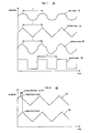
- FIG. 1 is a chart illustrating a number of different waveform types suitable for use with the present invention.
- FIG. 2 illustrates a pair of vibration profiles having a phase difference.
- FIG. 3 illustrates a pair of in-phase vibration profiles.
- FIG. 4 illustrates a linear motion vibration actuator for use with the present invention.
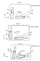
- FIGS. 5A-B illustrate an example of a linear motion vibration actuator in accordance with the present invention.
- FIGS. 6A-B illustrate another example of a linear motion vibration actuator in accordance with the present invention.
- FIGS. 7A-B illustrate a further example of a linear motion vibration actuator in accordance with the present invention.
- FIGS. 8A-B illustrate yet another example of a linear motion vibration actuator in accordance with the present invention.
- FIG. 9 illustrates a further example of a linear motion vibration actuator in accordance with the present invention.
- FIG. 10 illustrates a vibration device in accordance with aspects of the present invention.
- FIG. 11 illustrates the vibration device of FIG. 10 for generating a counterclockwise rotation in accordance with aspects of the present invention.
- FIG. 12 illustrates the vibration device of FIG. 10 for generating a clockwise rotation in accordance with aspects of the present invention.
- FIG. 13 illustrates the vibration device of FIG. 10 for generating a change in the direction of force in accordance with aspects of the present invention.
- FIG. 14 illustrates a vibration device employing non-orthogonal linear actuators in accordance with aspects of the present invention.
- FIG. 15 illustrates a vibration device employing a set of linear actuators for generation of a three dimensional force vector in accordance with aspects of the present invention.
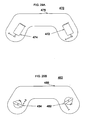
- FIG. 16 illustrates a game controller in accordance with aspects of the present invention.
- FIG. 17 illustrates a vibration device in accordance with aspects of the present invention.
- FIG. 18 illustrates another vibration device in accordance with aspects of the present invention.
- FIG. 19 illustrates a vibration device for generating a combined torque in accordance with aspects of the present invention.
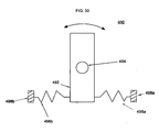
- FIG. 20 illustrates another vibration device for generating a combined torque in accordance with aspects of the present invention.
- FIG. 21 illustrates a rotary vibration actuator with eccentric mass in accordance with aspects of the present invention.
- FIG. 22 illustrates a vibration device with a pair of eccentric mass actuators in accordance with aspects of the present invention.
- FIG. 23 illustrates synchronous vibration of eccentric mass actuators in accordance with aspects of the present invention.
- FIGS. 24A-C illustrate a pivoting actuator in accordance with aspects of the present invention.
- FIGS. 25A-C illustrate another pivoting actuator in accordance with aspects of the present invention.
- FIG. 26 illustrates a pivoting actuator utilizing a pair of spring devices in accordance with aspects of the present invention.
- FIGS. 27A-F illustrate a further pivoting actuator in accordance with aspects of the present invention.
- FIG. 28 illustrates a synchronized vibration system employing rotary actuators in accordance with aspects of the present invention.
- FIGS. 29A-B illustrate game controllers in accordance with aspects of the present invention.
- FIG. 30 illustrates a rocking actuator in accordance with aspects of the present invention.
- FIG. 31 illustrates a vibration system in accordance with aspects of the present invention.
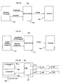
- FIG. 32 illustrates control of a vibration system in accordance with aspects of the present invention.
- FIG. 33 illustrates control of a vibration system in accordance with aspects of the present invention.
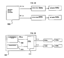
- FIG. 34 illustrates control of a vibration system in accordance with aspects of the present invention.
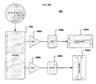
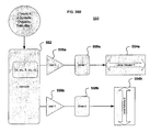
- FIG. 35 illustrates a vibration system in accordance with aspects of the present invention.
- FIGS. 36A-B illustrate equation parameter and pattern selection processing in accordance with aspects of the present invention.
- FIG. 37 illustrates a haptic interface system in accordance with aspects of the present invention.
- FIG. 38 illustrates another haptic interface system in accordance with aspects of the present invention.
- FIG. 39 illustrates control of vibration profiles in accordance with aspects of the present invention.
- FIG. 40 illustrates a vibration actuator in accordance with aspects of the present invention.
- FIG. 41 illustrates another vibration actuator in accordance with aspects of the present invention.
- FIG. 42 illustrates a vibration device controller in accordance with aspects of the present invention.
- an actuator is a device that can generate mechanical motion and force.
- Actuators can convert a source of energy into mechanical motion or force.
- the source of energy can be electrical, pneumatic, hydraulic, or another source.
- Examples of actuators include rotary and linear motors.
- Examples of electric actuators include DC, AC, and stepper motors.
- a vibration (or vibratory) actuator can impart repeated forces onto an object. These repeated forces can repeat a similar force profile over time during each repetition. Examples include rotary motors with eccentric masses, and linear actuators which move masses back and forth. These actuators can be DC, AC, stepper, or other types of actuators.
- a vibration actuator can repeat a similar force profile (waveform) in each cycle, or there can be variations in force profiles between cycles. Variations between cycles can be in amplitude, frequency, phase, and profile shape.
- the profile (also referred to as a waveform) of a repeated force cycle can be in a sinusoidal shape, triangular wave, a square wave, or other repeated profile as shown in FIG. 1 .
- the frequency of vibration describes how frequently a vibration cycle is repeated.
- a frequency of vibration, f is defined as the number of vibrations per unit time, and often is given in Hertz whose units are cycles per second.
- F(t) force as a function of time.
- A is the maximum amplitude of force.
- ⁇ is the phase of vibration in radians.
- a vibration actuator may impart repeated forces onto an object. Due to the dynamics of an actuator, a single actuator can impart forces at multiple frequencies at the same time. However, for the purposes of analyzing vibrations and describing vibration devices herein, the primary frequency of an actuator's motion means the frequency having the largest component of kinetic energy in it.
- the period of vibration can be defined by the time elapsed between the beginning of one vibration cycle and beginning of the next cycle. Thus to identify the period of vibration it is useful to identify the beginning of a cycle.
- One method for defining the beginning of cycle is to define the beginning of the cycle as the point with maximum amplitude in the profile.
- FIG. 1 is an amplitude versus time chart 10 showing the vibration profiles of a sine wave 12, a triangle wave 14, an arbitrarily shaped profile 16, and a square wave 18. The period for each of these profiles is designated by T.
- the sine wave 12, triangle wave 14, and arbitrary profile wave 16 all have a unique point of maximum amplitude during each repeated cycle, and this point of maximum amplitude is used to define the beginning of the cycle.
- the square wave 18 does not have a unique point of maximum amplitude within a cycle; in such cases a repeated point on the profile can be selected to designate the beginning of the cycle.
- the point at which the square wave 18 transitions from a low value to a high value is designated at the beginning point of the cycle, and used use to define the period of the repeated profile.
- any profile that can be represented as repeated cycles can represent a vibration.
- a frequency of vibration can also be identified when the shape of signal does not consist of exactly repeated profiles. variation in amplitude of the cycle and small changes in the shape of a cycles profile still allow one to identify a unique point that designates the beginning of the cycle. As long as a repeated point in the profile can be identified, then the beginning of each cycle, a vibration period, and vibration frequency can be determined.
- the phase of vibration defines the timing of the beginning of a cycle of vibration.
- a phase difference between two vibration waveforms is defined as the difference between the beginning of a vibration cycle in one waveform and the beginning of a vibration cycle in the other waveform. If there is a nonzero difference in the phase of vibration between two profiles, then the beginning of the cycles do not coincide in time.
- FIG. 2 is an amplitude versus time chart 20 showing two vibration profiles, 22 and 24, with a phase difference ⁇ between them.
- the phase difference ⁇ can be given in units of time, such as shown in FIG. 2 .
- the phase of vibration can also be given in radians for sinusoidal vibrations.
- the phase difference ⁇ between two waveforms is zero, then the two waveforms are considered to be in-phase, as shown in the amplitude versus time chart 30 of FIG. 3 .
- Synchronized vibration is defined as a vibration force formed by the superposition of two or more vibration waveforms where each of the waveforms include peaks that coincide in time with the peaks of the other waveforms on a regularly repeating basis.
- each of the waveforms would have the same frequency and a specified phase difference between them.
- Superposition can preferably be the vector sum of forces, torque, or forces and torque.
- the sources of these vibration waveforms are different vibration actuators.
- specified phase difference may range between and including 0° and 360°. In preferred embodiments, the specified phase difference is 0° or 180°.
- FIG. 3 illustrates two vibration waveforms of triangular profile that are synchronized. Both of these waveforms have the same frequency, they have different amplitudes, and the waveforms are in-phase. The maximum amplitude of both waveforms in FIG. 3 occurs at the same time.
- synchronized vibration profiles will have similar shaped profiles.
- vibration actuators with different shaped vibration profiles can also be vibrated synchronously by matching frequency of vibration and specifying the phase difference between the waveforms. The matching of phase and frequency of vibration can be done approximately and still result in synchronized vibration.
- Synchronized vibration can be generated by adding two vibration profiles together, where the amplitude of the second vibration profile is a multiple of the amplitude of the first vibration profile. This multiplying factor can be either positive or negative.
- the peak amplitude of force of each vibrating actuator occurs repeatedly at approximately the same time, then these actuators are in-phase and in synchronous vibration.
- the peak amplitude of force can be either in the positive or negative direction of the vibration actuators' or vibration device's coordinate system.
- a positive peak amplitude from one actuator occurs at approximately the same time as the negative peak amplitude of another actuator, then these actuators are in-phase and are in synchronous vibration.
- FIG. 4 An exemplary linear motion vibration actuator 100 is shown in FIG. 4 .
- the linear motion vibration actuator 100 contains a moving mass 102 and a base 104.
- the moving mass 102 moves relative to the base 104 in a back and forth linear motion.
- Force can be applied from the base 104 to the moving mass 102 and in a similar fashion from the moving mass 102 onto the base 104.
- the force transfer can occur, for instance, via magnetic forces, spring forces, and/or lead screw forces.
- Examples of linear actuators suitable for use in accordance with the present invention are described in U.S. Patent Nos. 5,136,194 and 6,236,125 , and in U.S. Patent Application No. 11/325,036 , entitled "Vibration Device," the entire disclosures of which are hereby incorporated by reference herein.
- the moving mass 102 in the linear motion vibration actuator 100 moves back and forth, forces are generated between the moving mass 102 and the base 104. These forces can be transmitted through the base 104 of the actuator 100 to an object that the actuator is mounted to (not shown).
- the moving mass 102 may also be attached to an object, such as a handle (not shown), that is external to the actuator 100, and may transmit forces directly to an object external to the actuator 100.
- the forces in the linear motion vibration actuator 100 may be magnetic forces, such as with a voice coil.
- the moving mass 102 may contain, for instance, a permanent magnet, electromagnet, ferromagnetic material, or any combination of these.
- the base 104 may contain, for instance, a permanent magnet, an electromagnet, ferromagnetic material, or any combination of these. Magnetic forces may be generated between base 104 and the moving magnet that generate acceleration and motion of the moving mass 104.
- a force in the linear motion vibration actuator 100 generated with an electromagnet can be modulated by controlling the current flowing through the electromagnet.
- FIGS. 5A-B One embodiment of linear motion vibration actuator 100 in accordance with the present invention is shown in FIGS. 5A-B as linear motion vibration actuator 110.
- Actuator 110 preferably contains a moving mass 112 that comprises an electromagnet, as well as a permanent magnet 116 attached to the base 114.
- the motion of the moving mass 112 is along the x axis as shown in the side view in FIG. 5A .
- the magnetization polarity of the permanent magnet 116 is along the x axis as shown by the North and South poles on the permanent magnet 116.
- the electromagnet is preferably configured as a coil wound about the x axis. As shown in the end view of FIG.
- the shape of the electromagnet is desirably cylindrical and the shape of the permanent magnet 116 is desirably tubular, although the electromagnet and the permanent magnet 116 may have any other configuration.
- both the electromagnet and the permanent magnet 116 may have ferromagnetic material placed adjacent to them to.increase the force output of the actuator 110.
- the force in the actuator 110 can be modulated by controlling the current in the electromagnet.
- the current in the electromagnet flows in one direction, then the magnetic force will push the moving mass 112 towards one side of the actuator.
- the moving mass 112 Conversely when the current in the electromagnet flows in the other direction, then the moving mass 112 will be pushed to the other side of the actuator 110.
- Increasing the amount of current in the electromagnet will increase the amount of force applied onto the moving mass 112.
- linear motion vibration actuator 120 preferably contains a moving mass 122 that comprises a permanent magnet, as well as an electromagnet magnet 126 attached to base 124.
- the motion of the moving mass 122 is along the x axis as shown in the side view in FIG. 6A .
- the magnetization polarity of the permanent magnet is along the x axis as shown by the North and South poles on the permanent magnet.
- the electromagnet 126 is preferably a coil wound about the x axis.
- the shape of the electromagnet 124 is tubular and the shape of the permanent magnet is cylindrical.
- both the electromagnet 124 and the permanent magnet of the moving mass 122 may have ferromagnetic material placed adjacent to them to increase the force output of the actuator 120.
- the force in the actuator 120 can be modulated by controlling the current in the electromagnet 124. When the current in the electromagnet 124 flows in one direction, then the magnetic force will push the moving mass 122 towards one side of the actuator 120. Conversely when the current in the electromagnet flows in the other direction, then the moving mass 122 will be pushed to the other side of the actuator 120. Increasing the amount of current in the electromagnet will increase the amount of force applied onto the moving mass 122.
- actuator 130 includes a moving mass 132 and a base 134.
- the moving mass 132 preferably comprises a permanent magnet.
- An electromagnet 136 at least partly surrounds the moving mass 132.
- the electromagnet 136 is desirably connected to the base 134.
- the actuator 130 in this embodiment preferably includes one or more springs 138 that are attached to the base 134 and to the moving magnet 132 at either end, as shown in the side view of FIG. 7A .
- the springs 138 are operable to generate forces in a direction that returns the moving mass 132 to a center position, for instance midway between either end of the electromagnet 136.
- the springs 138 function to keep the moving mass 132 close to the center position when the actuator power is off, and to provide a restoring force when the moving mass 132 is at one end of travel of the actuator 130.
- the stiffness of the springs 138 can be selected so that the natural frequency of the actuator 130 increases the amplitude of vibration at desired natural frequencies.
- This spring effect can be generated from a single spring, from a nonlinear spring, from extension springs, as well as compression springs. A number of such spring configurations which may be employed with the present invention are described in the aforementioned U.S. Patent Application No. 11/325,036 .
- FIGS. 8A-B Another embodiment of the linear motion vibration actuator 100 according to aspects of the present invention is shown in FIGS. 8A-B .
- This embodiment is similar to the embodiments shown in FIGS. 6A-B and 7-B in that actuator 140 includes a moving mass 142 including a permanent magnet, a base 144, and an electromagnet 146 coupled to the base 144 and at least partly surrounding the moving mass 142.
- the electromagnet 146 may be, e.g., rigidly or. semi-rigidly coupled such that a vibration force is transmitted from the actuator 140 to the base 144, for instance to enable a user to perceive the vibration force.
- a pair of permanent magnets 148 is attached to the base and are in operative relation to the moving magnet 142 at either end as shown in the side view of FIG. 8A .
- the permanent magnets 148 have poles, as shown by the N and S in FIG. 8A , which are configured to repel the moving mass 142 and to generate forces in a direction that returns the moving mass 142 to a center position.
- the permanent magnets 148 function to keep the moving mass 142 close to a center position when the actuator power is off, and to provide a restoring force when the moving mass 142 is at one end of travel of the actuator 140.
- the size of the permanent magnets 148 attached to the base 144 can be selected so that the natural frequency of the actuator 140 increases the amplitude of vibration at desired natural frequencies.
- the actuator 140 may be controlled so that one or more natural frequencies are selected during different modes or times of operation.
- Use of repulsive magnetic forces as shown in FIG. 8A to generate centering forces on the moving permanent magnet of the moving mass 142 can provide lower friction than use of springs 138 as shown in FIG. 7A , and thus can generate increased actuator efficiency and smoothness.
- a number of configurations showing use of permanent magnets to center a moving mass, which are suitable for use in the present invention, are described in the aforementioned "Vibration Device" patent application.
- FIG. 9 A further alternative embodiment of the linear motion vibration actuator 100 in accordance with the present invention is shown in FIG. 9 .
- This embodiment comprises actuator 150, which is similar to a solenoid in that it has a ferromagnetic moving plunger 152 for moving relative to a base 154.
- the plunger 152 is pulled into an electromagnetic coil 156 when current flows through the coil 156.
- the coil 156 is coupled to the base 154.
- a ferromagnetic end piece 158 can be located within or at the end of the coil 156 to increase the force output of the actuator 150.
- a spring device 160 may be positioned opposite the end piece 158. The spring device 160 is preferably employed to retract the plunger 152 out of the coil 156. As shown in FIG.
- both an end of the coil 156 and an end of the spring 160 are desirably fixed to the base 154 of the actuator 150.
- the coil 156 and the spring 160 may be fixed to a single base at different sections thereon, or may be fixed to separate base elements that are coupled together.
- the current in the coil 156 can be turned on and off to generate a vibration force.
- FIG. 10 A preferred embodiment of a vibration device 200 according to the present invention is shown in FIG. 10 .
- the vibration device 200 preferably includes two linear motion vibration actuators mounted on to it, namely actuator 202 and actuator 204.
- the actuator 202 includes a moving mass 206 and the actuator 204 includes a moving mass 208.
- the vibration actuators 202, 204 are attached to the vibration device 200 in a manner that transmits the force from the vibration actuators 202, 204 to the vibration device 200.
- the vibration device 200 has an enclosure or base (not shown) to which the vibration actuators 202, 204 are connected.
- the vibration actuators 202, 204 are desirably attached in a relatively rigid fashion to the vibration device enclosure or base. Rigid attachment provides a common base to the vibration device 200, upon which forces from both vibration actuators 202, 204 are applied.
- the two actuators 202, 204 are mounted at approximately right angles to each other.
- the force generated by actuator 202 is shown as force vector F 1
- the force vector from actuator 204 is shown as F 2 .
- vectors and matrices are designated by bold font and scalars are designated without bolding.
- the combined force generated by the vibration device 200 is the vector sum of the vibration forces from both of the actuators 202, 204, and is shown in FIG. 10 as vector F combined .
- the combined force, F combined , applied by the vibration actuators 202 and 204 onto the vibration device 200 is a superposition of the vibration forces from each actuator, and is a function of time, t.
- Both actuators 202, 204 can be operated in a vibratory fashion.
- Other profile vibrations including square waves, triangle waves, and other profiles can also be implemented with each actuator.
- the vibration device With such in-phase and synchronous vibration the vibration is synchronized, then the peak forces from both linear motion vibration actuators will occur at the same instances during each cycle of vibration.
- the net direction of vibration force is the vector combination of [ a 1 A 1 + a 2 A 2 ].
- the vibration device in synchronized vibration and in-phase vibration, the vibration device generates a vibration force at a specified frequency in a specified direction that results from the vector combination of forces from the direction and magnitude of each of the actuators in the device. It is possible to control the magnitude of vibration in each linear motion vibration actuator, and thereby control the net direction of vibration of F combined .
- the vibration frequency, ⁇ , phase ⁇ , and waveform of each actuator are substantially identical.
- ⁇ 2 may be set to be substantially equal to ⁇ 1 and ⁇ 2 may be set to be substantially equal to ⁇ 1 .
- ⁇ 2 may be set to within 10% of the value of ⁇ 1 , more preferably to within 5% of the value of ⁇ 1 .
- ⁇ 2 may be set to within 10% of the value of ⁇ 1 , more preferably to within 5% of the value of ⁇ 1 .
- the frequencies and/or phases may be set exactly equal to one another.
- the frequencies, phases, and/or waveforms of each actuator may be set so that a user would not be able to notice the difference in frequency, phase or waveform.
- the vibration device is used in a haptic application to generate force sensations on the user, small variations may occur which may not be detected by the user or which cannot be significantly felt by the user.
- force sensations in a haptic application or in a vibratory feeder application may vary minutely so that user performance in the haptic application or performance of the vibratory feeder is not significantly changed.
- waveform p(t) may be used to represent the waveform shape over time t.
- both actuator 202 and actuator 204 are desirably vibrated at the same amplitude, and the corresponding F combined is at approximately a 45 degree angle between the actuators 202, 204.
- the actuator 202 is vibrating at peak amplitude as illustrated by the peak position of moving mass 206 at the end of travel limits of actuator 202.
- actuator 204 is vibrating at a lower peak amplitude, as illustrated by the peak position of moving mass 208 closer to the middle of travel limits of actuator 204.
- the lower peak force is also illustrated in FIG. 11 by the shorter length vector for F 2 .
- the direction of the combined force, F combined is the result of vector addition of F 1 and F 2 , and for vibrations illustrated in FIG. 11 is rotated counterclockwise relative to the direction shown in FIG. 10 .
- the direction of combined force can be rotated in the clockwise direction as shown in FIG. 12 .
- the vibration case illustrated in FIG. 12 shows the peak amplitude of vibration of actuator 202 reduced relative to that shown in FIG. 10 , while the peak amplitude of actuator 204 remains high.
- the vector addition of F 1 and F 2 results in a clockwise rotation of F combined in FIG. 12 relative to the direction shown in FIG. 10 .
- vibration device 210 includes a first actuator 212 and a second actuator 214, having respective moving masses 216 and 218.
- FIG. 14 represents a two dimensional embodiment where two linear motion vibration actuators 212, 214 are aligned with an xy plane. In this embodiment, it is not necessary for the actuators 212, 214 to be orthogonal to each other.
- a 1 and A 2 are respectively the amplitudes of vibration of actuators 212 and 214, while a 1 and a 2 are respectively the unit vectors specifying the direction of vibration of actuators 212 and 214.
- a matrix of actuator directions, D L can be created where each of its columns is a unit vector that corresponds to the direction of vibration of a linear motion vibration actuator in a vibration device.
- the vectors a 1 and a 2 will be 2x1 vectors and the matrix D L will be 2x2.
- D L a pseudo inverse of matrix D L
- D L + D L T ⁇ D L D L T - 1
- the combined force vector, F combined in terms of a direction of vibration and amplitude.
- the combined amplitude of vibration can be specified by the scalar A combined
- the direction of vibration can be specified by an angle, theta, as shown in FIG. 14 .
- Equation 25 provides the scalar magnitude of A 1 and A 2 .
- vibration waveform can be generated directly using the results of Eq. Avec.
- the waveform can be generated using absolute values of A 1 and A 2 but with one waveform completely out of phase with the other waveform.
- a sine wave is defined to be completely out of phase when it is 180 degrees out of phase.
- General waveforms are defined to be completely out of phase when the maximum positive amplitude of vibration of one waveform concedes with the maximum negative amplitude of the other waveform.
- a depiction of two actuators vibrating completely out of phase is shown in FIG. 13 . Two actuators vibrating completely out of phase are also considered to be in synchronized vibration.
- Another configuration according to aspects of the present invention is a three dimensional configuration, where there are at least 3 linear motion vibration actuators as shown in FIG. 15 .
- actuators 222, 224 and 226 each include a moving mass 228, 230 and 232, respectively.
- the actuators 222, 224 and 226 are preferably orthogonal to each other and aligned with an xyz coordinate system.
- the actuators are not necessarily orthogonal to each other; yet the force vectors of the actuators span the three dimensional vector space.
- an arbitrary direction of three dimensional force can be generated.
- the combined direction of vibration can be specified by the 3x1 unit vector, a combined .
- Vibration devices may include an arbitrary number of actuators in arbitrary locations and orientations.
- FIG. 16 illustrates a vibration device 240 having a pair of actuators 242 and 244.
- the actuators 242 and 244 include moving masses 246 and 248, respectively.
- vibration device housing 250 is configured as a hand held game controller for computer or video games.
- Linear motion vibration actuator 242 is shown as being located in the left handle and linear motion vibration actuator 244 is shown as being located in the right handle.
- the actuators 242 and 244 need not be orthogonal, and need not be in the same plane.
- vibration device 260 includes a first linear motion vibration actuator 262 and a second linear motion vibration actuator 264. As shown, the actuators 262, 264 are located on top of each other. An advantage of such a configuration is that the actuators 262, 264 create little torque about the center of the vibration device 260, which may be desirable in some vibration applications.
- FIG. 18 illustrates a game controller 270 having two linear actuators, 272 and 274 disposed perpendicular to each other.
- the actuators 272 and 274 are preferably rigidly mounted to case 276 of a game controller.
- the actuators 272 and 274 could be mounted in a plane of any angle; however, they are preferably mounted in a horizontal plane of the case 276.
- the actuators 272 sand 274 do not have to be located one on top of the other; rather they can be attached to the same rigid body, such as the case 276 of a game controller.
- the actuators do not have to be at right angles to each other. Desirably, the actuators are positioned relative to one another with different orientations.
- vibration device 280 includes two linear motion vibration actuators, 282 and 284, which are aligned in their orientation but separated by a distance D.
- Actuator 282 includes moving mass 286 and actuator 284 includes moving mass 288.
- the actuators 282, 284 may be vibrated such that the moving mass 286 in actuator 282 is at a negative extreme along the y axis when the moving mass 288 in actuator 284 has a positive extreme along the y axis. In this fashion the two actuators 282, 284 generate a combined torque when vibrated in a synchronous fashion.
- FIG. 19 A further embodiment of a vibration device according to the present invention is shown in FIG. 19 .
- vibration device 280 includes two linear motion vibration actuators, 282 and 284, which are aligned in their orientation but separated by a distance D.
- Actuator 282 includes moving mass 286
- actuator 284 includes moving mass 288.
- the actuators 282, 284 may be vibrated such that the moving mass 286 in actuator 282 is at a negative
- FIG. 19 could be operated, in one example, such that the moving masses 286 and 288 move in the same direction when synchronized, and thereby generate a combined force along the y axis. In this fashion the configuration shown in FIG. 19 could be used to generate a combined torque, a combined force, or a combination of force and torque.
- FIG. 20 An alternative embodiment of a vibration device 290 in accordance with aspects of the present invention is shown in FIG. 20 .
- three linear motion vibration actuators 292, 294 and 296, each having a moving mass, are orientated on an xy plane.
- the combined torque and force are superpositions of the forces and torques generated by each actuator. Since there are three actuators that can be controlled independently, the components of the force along the x axis, the force along the y axis, and the torque about a selected point on the xy plane can all be modulated independently.
- the vibration actuators may be attached to the vibration device in a rigid, a semi-rigid or a non-rigid fashion. Even when vibration actuators are attached in a non-rigid fashion to a vibration device, the vibration device is operable to transmit the superposition of forces from all vibration actuators. When vibration actuators are attached in a rigid fashion to a vibration device, the combined force applied by the vibration device becomes less dependent on the location where the vibration device transmits force and torques to other bodies. In addition, the more rigid the attachment between the vibration actuators and the vibration device, the more uniform the timing of the force superposition becomes at all points of the vibration device.
- Vibration devices in accordance with the present invention can be built with rotary vibration actuators as well as with linear motion vibration actuators.
- the cost to manufacture rotary vibration actuators is less than the cost to manufacture linear motion vibration actuators.
- a rotary vibration actuator may comprise, for example, a DC motor, a rotary solenoid, a rotary stepper motor, a servo motor, or other type of rotary actuator.
- a DC motor a DC motor
- a rotary solenoid a rotary stepper motor
- a servo motor a servo motor
- One advantage of rotary actuators is their relatively low cost.
- the servo motor uses a position sensor and/or a velocity sensor for feedback. In some situations the rotary stepper motor may be more desirable because it allows for control of position and velocity without the use of a sensor.
- FIG. 21 shows a rotary vibration actuator 300 suitable for use with the present invention.
- the actuator 300 includes an eccentric mass 302 coupled to a rotary actuator 304 along a shaft 306. As the rotary actuator 304 is rotated, a centrifugal force is generated in the radial direction aligned with the eccentric mass 302 as shown by the vector CF in FIG. 21 .
- a pair of rotary vibration actuators can be configured to achieve a vibration force that is aligned with a single direction of motion. Accordingly, a pair of such rotary actuators can be used when a vibration force in a specified direction is required.
- a vibration device can be built, by way of example only, with two rotary vibration actuators that rotate in opposite directions, as shown in FIG. 22 .
- the vibration device 310 includes a pair of rotary vibration actuators 312 and 314, each having an eccentric mass 316 and 318, respectively.
- Actuator 312 preferably rotates clockwise, and actuator 314 preferably rotates counterclockwise. In the orientation shown the centrifugal force vectors from both actuators are aligned with the y axis and superimpose to create a combined force vector, CVF , in the y direction.
- rotary vibration actuators it is possible to create synchronized vibration in an analogous fashion to the synchronized vibration described with linear motion vibration actuators.
- synchronized vibration is defined to occur where two rotary actuators rotate in approximately the same plane at the same angular velocity in opposite directions, and where the relative angle between the actuators is controlled, such that the actuator centrifugal force vectors align repeatedly in the direction of desired vibration force.
- the direction of vibration force can be controlled with a pair of rotary (or rocking) vibration actuators by controlling the angle at which the centrifugal force vectors become aligned. Therefore, it is possible to control the direction of combined force with rotary actuators in a fashion analogous to how the direction of combined force can be controlled with multiple linear vibration actuators.
- FIG. 23 shows the embodiment of two rotary vibration actuators as described with respect to FIG. 22 , wherein the actuators are controlled in synchronized vibration for a number of positions.
- the combined force vector, CFV remains in the y axis, and its magnitude changes according to the rotary position of the actuators.
- the maximum combined force vector occurs when the centrifugal force from both rotary actuators are aligned.
- FIGS. 24A-C illustrate respective front, side and bottom views of an exemplary pivoting actuator 400, which includes a mass 402 operable to pivot relative to a rotary actuator 404.
- the mass 402 is connected to the rotary actuator 404 via a shaft 406.
- the center of mass of the mass 402 can be located anywhere on the body of the mass 402. Thus, the center of mass may be concentric with the axis of rotation, or eccentric to the axis of rotation.
- the pivoting actuator 400 may be configured to function in a manner similar to the rotary vibration actuators discussed above.
- the rotary actuator 404 may be affixed to a support 408, which, in turn, may connect to another object (not shown).
- a spring device 410 couples the pivoting mass 402 to a support 412, which may be the same or a different support than the support 408.
- FIG. 25A illustrates the pivoting actuator 400 when the spring device 410 is in a rest state when the pivoting mass 402 is in a central position.
- the mass 402 may pivot in either a clockwise or counterclockwise manner.
- FIG. 25B illustrates counterclockwise operation.
- the spring device 410 is in a compressed state.
- the spring device 410 is under a compression force that is primarily linear and is applied toward the right hand side of the figure.
- FIG. 25C illustrates clockwise operation of the mass 402.
- the spring device 410 is in an uncompressed state in response to a force that is primarily linear and is applied toward the left hand side of the figure.
- Vibration forces and/or torques can be generated with the pivoting actuator 400 as shown in FIGS. 25A-C .
- the pivoting actuator 400 can be activated to pivot the pivoting mass 402 first clockwise and then counterclockwise, or vice versa.
- the spring device 410 generates a vibration force, a torque, or both a vibration force and torque onto the object to which it is affixed via the support 408.
- the pivoting mass 402 has a center of mass concentric with the axis of rotation
- the pivoting mass 402 can be used to generate a vibration torque.
- the pivoting mass 402 has a center of mass eccentric with the axis of rotation
- the pivoting mass 402 can be used to generate a vibration force.
- vibration forces and/or torques can be generated by moving a mass back and forth. It is possible to define the beginning of a vibration waveform as an instance at which a mass reverses its direction of motion.
- the reversal of direction is a reversal of translation.
- the reversal of direction is a reversal of rotation.
- the reversal of motion of a mass in an actuator may include both translation and rotation.
- actuators having a spring device attached to a moving mass energy can be built up in the spring device, especially when the mass is moved back and forth close to a natural frequency of the mass and spring system.
- the maximum vibration force can occur at the maximum deformation of the spring device, which can occur when the mass reaches its maximum excursion and reverses its direction. Accordingly, moving masses in two (or more) actuators that are operating in synchronized vibration, can reverse direction at approximately the same time.
- An alternative method for generating vibration would be to operate the pivoting actuator 400 in a clockwise (or counterclockwise) direction and then deactivate the pivoting actuator 400 while allowing the spring device 410 to rotate the pivoting mass 402 in the counterclockwise (or clockwise) direction.
- This approach would allow one to use pivoting actuators and control circuitry that only operates in a single direction.
- FIG. 26 illustrates a variation of the pivoting actuator 400, namely pivoting actuator 400', which desirably includes the pivoting mass 402 operable to pivot relative to the rotary actuator 404, and which is connected thereto via the shaft 406.
- the rotary actuator 404 may be affixed to the support 408, which, in turn, may connect to another object (not shown).
- a first spring device 410a couples the pivoting mass 402 to a first support 412a
- a second spring device 410b also couples the pivoting mass 402 to a second support 412b.
- the supports 412a and 412b may be a single support, separate supports that are physically connected, or physically disconnected supports.
- One or both of the supports 412a,b may be the same or a different support than the support 408.
- the pivoting actuator 400 may essentially include a stator and a rotor.
- the stator may be stationary and desirably contains permanent magnets and/or electromagnets.
- the rotor is operable to pivot and can contain permanent magnets and/or electromagnets.
- the polarity of the magnets in the stator and rotor can be configured so that activation of the electromagnets causes an electromagnetic torque to be exerted onto the rotating mass 402.
- the spring device 410 is configured to operate in a generally linear fashion.
- the embodiments shown in FIGS. 25A-C have both a mass and a spring, and thus have a resonant frequency. If the actuator is excited at or close to this resonant frequency large amplitude vibrations can build up. However, it can be desirable to operate the vibration device at a range of frequencies. It is possible for a device to have a variable resonant frequency with use of nonlinear spring forces, as discussed in the aforementioned "Vibration Device" patent application. Accordingly, one could use a nonlinear spring in the vibration device to achieve larger amplitude of vibration over a range of frequencies.
- pivoting actuator 420 has a mass 422 operable to pivot relative to a rotary actuator 424.
- the mass 422 is connected to the rotary actuator 424 via a shaft 426.
- the rotary actuator 424 may be affixed to a support 427, which, in turn, may connect to another object (not shown).
- a spring device 428 couples the pivoting mass 422 to a support 427', which may be the same or a different support than the support 427.
- the spring device 428 is desirably placed in-line with the pivoting mass axis.
- the pivoting mass 422 is rotated a small amount about the center position very little lengthening occurs in the spring device 428. Accordingly, the effective spring constant is low and the resonant frequency is low.
- Low frequency operation is desirable in some situations, for instance in games that have low frequency effects.
- games may generate actions or events in the sub-200 Hertz range, such as between 15 and 150 Hertz.
- the actions or events may be as low as 20-50 Hertz or lower, such as about 10-20 Hertz.
- Examples of such actions/events include gunshots, automobile related sounds such as a car spinning out of control, and helicopter related sounds such as the whirring of the rotor blades.
- Eccentric mass actuators may not be suitable to generate a haptic sensation in this frequency range, but pivoting actuators or linear actuators may generate such frequencies.
- the lengthening of the spring device 428 increases as shown in FIGS. 27B and 27C . Accordingly, for larger amplitudes of rotation, the effective spring constant is higher and the natural frequency of the system is higher. In order to quickly ramp up the vibration amplitude when a nonlinear spring force is used, the excitation frequency can be varied so that it always matches the natural frequency of the vibration device.
- FIG. 27D illustrates a rotating actuator 430 having a rotating mass 432 coupled to rotary actuator 434 via shaft 436.
- the rotary actuator 434 is desirably coupled to a support 437, which, in turn, may connect to another object (not shown).
- a spring device such as a torsion spring 438 is attached between the rotating mass 432 and the rotary actuator 434.
- one end or tang 439a of the torsion spring 438 is attached to the rotating mass 432, and the other end or tang 439b is attached to the support 437 (or, alternatively, to the rotary actuator 434 itself).
- Torsion spring 438 may be employed because such spring devices permit a large degree of rotation of the rotating mass 432 relative to the rotary actuator 434 and the support 437.
- FIGS. 27E and 27F illustrate a further rotating actuator, namely rotating actuator 440.
- the rotating actuator 440 includes a rotating mass 442 having a slot 443 therein, a rotary actuator 444, and a shaft 446 coupling the rotating mass 442 to the rotary actuator 444.
- the rotary actuator 444 is desirably coupled to a support 447, which, in turn, may connect to another object (not shown).
- a pin 445 is held within the slot 443.
- a spring device 448 is coupled at one end or tang 449a to the pin 445.
- the spring device 448 is coupled at the other end or tang 449b to a support 447'.
- the support 447' is preferably different from the support 447, or, alternatively, is preferably a different section of the support 447 from where the rotary actuator is coupled.
- FIG. 27E shows the spring device 448 in a "rest” position.
- FIG. 27F shows the spring device 448 in a "compressed” position.
- the rotating mass 442 may be rotating in a clockwise direction.
- the pin 445 moves relative to the slot 443, but the spring device 448 remains in substantially the same orientation relative to the support 447'.
- the force applied onto the fixed 447' remains in relatively the same direction as the moving mass 442 rotates.
- the gap would create a non-linear force effect on the rotating mass 442, which could aid in increasing the magnitude of vibration.
- the gap would allow the shaft 446 to more quickly reach higher speeds and for the rotating actuator 440 to more quickly build up rotating inertia.
- actuators While several types of actuators have been described above that may be used with the present invention, other types of actuators may also be employed so long as they can be controlled as described herein. For instance, piezoelectric devices without separate or distinct “moving" and “stationary” masses may be employed either alone or in combination with other actuator types to impart vibratory forces in the manners described herein.
- FIG. 28 illustrates a synchronized vibration system 450, which may comprise two vibration devices 452 and 454, such as any of those of FIGS. 24A-C , 25A-C , 26 and/or 27A-F .
- the vibration devices 452 and 454 are preferably mounted onto a base plate 456 in a generally orthogonal manner as shown, although orthogonality is not required.
- the vibration device 452 is preferably a horizontal vibrator that desirably has a spring device 458 which applies primarily horizontal forces onto the base plate 456.
- the vibration device 454 is preferably a vertical vibrator that desirably has a spring device 460 that applies primarily vertical forces onto the base plate 456.
- An alternative embodiment of the present invention includes two rotary vibration actuators whose planes of vibration are not the same; however, in this case the two planes are not orthogonal to each other.
- the component of centrifugal force from one actuator that can be projected onto the plane of the other actuator can be used to achieve a component of synchronous vibration.
- two or more vibration devices may be mounted devices into a game controller, as shown in FIG. 29A .
- a game controller 470 includes a pair of vibration devices 472 and 474 mounted in both the right and left handles, respectively, of housing 476.
- the directions of vibration of the vibration devices 472 and 474 are preferably not aligned, and thus it is possible to control the direction of vibration using the synchronized vibration approach discussed herein.
- FIG. 29B illustrates a game controller 480 having a pair of vibration devices 482 and 484 within a housing 486 where the axis of the rotating shafts in both rotary actuators are aligned, yet the spring forces are not aligned.
- FIG. 30 illustrates yet another variation similar to the rotary and pivoting vibration devices.
- a rocking actuator 490 preferably includes a rocking weight 492 rotatable about a shaft 494. Desirably, one end of the rocking weight 492 is operatively coupled via a first spring device 496a to a first support 498a. The same end of the rocking weight 492 is also desirably operatively coupled via a second spring device 496b to a second support 498b.
- the supports 498a and 498b may be a single support, separate supports that are physically connected, or physically disconnected supports.
- the rocking actuator 490 may be implemented in a device such as a game controller in any of the configuration described above.
- a controller for synchronized vibration of a pair of rotary vibration actuators specifies the angular position of each rotating shaft, such that the angle where the centrifugal force vectors are aligned is the desired direction of force vibration and the angular position is incremented such that the rotational velocity matches the desired vibration frequency.
- Vibration device controller 502 specifies the desired vibration effect and one or more driver circuit(s) 504a, 504b, ... , 504 N provide the necessary power to actuators 506a, 506b, ... , 506 N . While each actuator 506 is shown as being powered by a separate driver circuit 504, it is possible for multiple actuators 506 to be driven by one driver circuit 504.
- the controller 502 may be, by way of example only, a microprocessor and the driver circuit(s) 504 may be, for instance, one or more electrical amplifiers.
- the controller 502 and drive circuit 504 may be integrated into a single microprocessor or single electrical circuit.
- the control method in this figure is for a configuration with N actuators, where N is an arbitrary number of actuators.
- FIG. 32 shows a control method for two actuators.
- the controller 502 specifies the desired vibration amplitude, A, frequency, f, and phase, p, for each actuator 506.
- the amplitude, frequency, and phase of actuator 506a (A1, f1, p1) may differ from the amplitude, frequency, and phase of actuator 506b (A2, f2, p2).
- the profile/waveform of the desired vibration force may be a sine wave, square wave, triangle wave, or other profile, such as is discussed above with regard to FIG. 1 .
- the actual vibration profiles/waveforms of the actuators 506a,b may differ from the desired vibration profiles due the dynamics of the drive circuits 504a,b and actuators 506a,b.
- FIG. 33 shows a control method where the frequency of vibration, f, is the same for both actuators 506a,b.
- FIG. 34 shows a control method where the frequency of vibration, f, and the phase of vibration, p, are the same for both actuators 506a,b.
- the actuators 506a,b are desirably driven synchronously such that the peak amplitude of vibration will occur approximately at the same time for both actuators 506a,b.
- the amplitude of vibration may differ between the.actuators 506a,b.
- FIG. 35 shows a control embodiment in accordance with the present invention where the vibration device controller 502 includes an internal direction and amplitude controller 508, an internal frequency controller 510, and an internal vibration controller 512.
- the direction and amplitude controller 508 desirably specifies the combined vibration amplitude, A combined , and the direction of vibration theta.
- the frequency controller 510 desirably specifies the vibration frequency, f.
- the vibration controller 512 uses the inputs of theta, A combined , and f to output vibration commands to the individual actuators 506a,b.
- the vibration controller 512 is operable to output various waveforms including sine waves, square waves, triangle waves, or other profiles as discussed herein.
- the output from the vibration device controller 502 shown in FIG. 35 provides the magnitude of vibration as a function of time to each drive circuit 504a,b.
- t time
- ⁇ is the vibration frequency in radians per second.
- the parameter p is the phase of vibration and may be set to zero.
- the output A 1 (t) and A 2 (t) from equation 28 can be applied directly to the vibration actuators to generate a combined vibration direction corresponding to the angle theta.
- some vibration actuators may have a nonlinear relationship between the command magnitude and the magnitude of vibration.
- it is possible to generate vibration in the direction theta by using a linearization function that adjusts the magnitude of A 1 and A 2 to compensate for the nonlinearity of the actuator, as shown in the following equation.
- a ⁇ 1 t A ⁇ 2 t linearization_function D - 1 ⁇ Acombined cos theta sin theta ⁇ sin ⁇ ⁇ t + p
- the linearization equation described above can be a lookup table or a scaling algorithm or other type of function.
- the ability to control the direction of vibration over time is an important advantage of the present invention.
- the ability to control vibration direction can be used in vibratory feeders to direct parts in a desired direction.
- FIG. 36A illustrates a system 550 showing the input of various input parameters of amplitude, phase and position (or time) for a pair of linear actuators.
- a computer 552 receives input of the parameters, which are preferably entered using a computer keyboard (not shown); however, the parameters also could be input using a graphical user interface, analog potentiometers, or many other means generally known to those skilled in the art.
- the appropriate output waveforms for linear actuators 554a and 554b are then computed using the computer 552. Each waveform is preferably independent. While computation may be performed using an analog computer, a digital computer is preferred.
- each actuator 554a,b is then preferably fed into respective digital-to-analog (“DAC") converters 556a and 556b, which convert the output to the appropriate analog waveform.
- DAC digital-to-analog
- the analog waveforms are then fed into the appropriate driver circuits 558a and 558b.
- DAC digital-to-analog
- Those skilled in the art could use other means to modulate the linear vibrations of each actuator 554a and 554b, for example via PWM. Varying the parameters produces an extremely broad range and rich set of haptic sensations for the end user.
- Such patterns include circles, ellipses and straight lines.
- the amplitude and duration of the patterns may be precisely controlled over time.
- a sequence of patterns may be generated as desired.
- FIG. 36B illustrates the system 550 where the input of various input parameters includes input of pattern number, amplitude, duration and start-time for the vibration device using compound vibrations.
- the parameters are preferably entered using a computer keyboard.
- the appropriate output waveforms for each linear actuator are then computed at computer 552.
- the digital output for each actuator 554a and 554b is then fed into DACs 556a and 556b for conversion to the appropriate analog waveforms.
- the waveforms are then fed into the driver circuits 558a and 558b.
- the various parameters produce an extremely broad and rich set of haptic sensations for the end user.
- Haptic interfaces provide force sensation to a user.
- Haptic Interfaces include computer gaming controllers, robot controllers, surgical tool controllers, as well as other devices where a force sensation is provided to a user.
- FIG. 37 An embodiment 600 of the present invention with a haptic interface application is shown in FIG. 37 .
- a systems controller 602 provides force commands to a haptic interface 604 which generates forces which result in force sensations to user 606.
- the systems controller 602 may be microprocessor, a central processing unit, an ASIC, a DSP, a game controller, an analog controller, or other type of controller or any combination thereof.
- the user 606 can input commands to the haptic interface 604 that are transmitted as user commands back to the system controller 602.
- the user commands can be input through pressing buttons, moving joysticks, squeezing the haptic interface at various level forces, moving the haptic interface, applying force and torque onto the haptic interface and through other means.
- a graphical display 608 which receives an image command from the system controller 602 and displays a visual image to the user 606.
- the graphical display 608 may be, for instance, a computer monitor, a television monitor, an LCD display, a plasma display, a combination of light sources, or other type of means for generating a graphical image.
- a haptic interface application can also be implemented without a graphical display 608.
- a haptic interface application can include a simulation of a virtual environment or representation of a real environment to the user 606.
- a systems controller method of control can be based upon this real or virtual environment.
- Typical simulated environments include games, driving and flight simulations, surgical simulations, and other types of simulations.
- Typical real world environments include control of robots and remote machines, long distance interactions, and other types of environments. It is often desirable that a haptic interface provide force sensations that correlate with the real or simulated environment in which the haptic interface is being used.
- FIG. 38 Another embodiment 620 having a haptic interface application is shown in FIG. 38 .
- This embodiment is similar to the one of FIG. 37 , and includes a systems controller 622, which provides force commands to a haptic interface 624 that generates forces which result in force sensations being received by user 626.
- a graphical display 628 is also provided for receiving image commands from the system controller 622 and for displaying a visual image to the user 626.
- the haptic interface 624 desirably includes a vibration device 630 having vibration actuators (not shown), a vibration controller 632, driver circuits 634 which drive the vibration device actuators, and an input device 636, which can detect user input and which can include buttons, joysticks, and pressure sensors.
- the components of the haptic interface 624 may be of any of the configurations described herein.
- the graphical display 628 preferably presents a two dimensional image.
- the graphical display 628 shows an object of interest at a direction specified by the angle theta. It is may be desirable that the force sensation felt by the user 626 correspond to the image on the graphical display in terms of direction, such as theta, and other attributes.
- the embodiment shown in FIG. 38 can be utilized so that the force sensations felt by the user 626 are generated by the vibration device controller 632 specifically to correspond to the image on the graphical display 628.
- the vibration device controller 632 may specify one or more of the amplitude of vibration, A combined , direction of force, theta, and frequency of vibration, f, as described above.
- the values of A combined , theta, and/or f can be selected to correspond to the image on the graphical display 628 and the environment being used by the system controller 622.
- the complete force effect (including frequency, amplitude, combined direction of force and torque, and duration of force effect) generated by the vibration device may correlate events within a graphical computer simulation. Several examples of such operation follow.
- a first example involves the simulation of a user firing a gun.
- the vibration device controller 632 could specify the angle theta to represent the direction of a gun firing, the amplitude of vibration, A combined , to represent the amplitude of the gun recoil, and the frequency of vibration, f, to represent the frequency of bullets leaving the gun.
- a second example involves an impact between objects.
- the vibration device controller 632 may specify the angle theta to represent the direction of impact, and the amplitude of vibration, A combined , to represent the amplitude of impact.
- a third example involves driving a vehicle.
- the vibration device controller 632 could specify the angle theta to represent the direction of vehicle motion, the frequency of vibration, f, to represent the frequency of vehicle vibration as it drives over bumps in the road or the speed of the vehicle, and the amplitude of vibration, A combined , to represent the amplitude of bumps in the road.
- a fourth example involves a car or spacecraft spinning out of control.
- the vibration device controller 632 could specify an angle theta that represents the vehicle's orientation.
- the angle theta can vary over time. The rate at which the angle theta can be different than the vibration frequency. Typically the frequency at which a vehicle spins would be significantly lower than typical vibration frequencies.
- An algorithm that can be used to create the vehicle spinning described above varies the direction of vibration continually.
- the direction of vibration may be rotated at a rate of ⁇ radians per second, using the equation below:
- a ⁇ 1 t A ⁇ 2 t D - 1 ⁇ Acombined cos ⁇ t sin ⁇ t ⁇ sin ⁇ ⁇ t + p
- Equation 30 illustrates that the frequency of direction change, ⁇ , can be modified independently from the frequency of vibration ⁇ .
- a user such as user 606 or 626 can sense both the frequency of vibration and the direction of vibration. In this fashion, sensations at both the ⁇ and ⁇ frequencies can felt by the user. It is possible to set the frequency ⁇ much lower than the frequency ⁇ , thereby overcoming a limitation of known devices.
- ⁇ may vary between 10 Hz and 100 Hz while ⁇ may be on the order of 1 Hz.
- ⁇ may vary from between about 5% to 20% of ⁇ .
- ⁇ and ⁇ may be similar or the same, or, alternatively, ⁇ may be larger than ⁇ . All of these examples will depend on the specific effect that is desired.
- Low frequency operation is desirable in some situations, for instance in games that have low frequency effects.
- games may generate actions or events in the sub-200 Hertz range, such as between 1 and 150 Hertz.
- the actions or events may be as low as 2 Hertz or lower, such as about 0.5 - 1 Hertz.
- Examples of such actions/events include gunshots, automobile related sounds such as corresponding to a car spinning out of control, and helicopter related sounds such as the whirring of the rotor blades.
- a traditional eccentric mass actuator may not be suitable to generate a haptic sensation in this frequency range; however, two or more vibration actuators operated in synchronized vibration may generate such frequencies.
- ⁇ is not limited to any particular rate or range of rates.
- ⁇ may be a relatively low rate to represent a slow spinning action, e.g., of a car spin out at less than 10 miles per hour, or ⁇ may be a relatively high rate to represent a fast spinning action, e.g., of a car spin out at a speed in excess of 40 miles per hour.
- ⁇ is not limited to any particular frequency of vibration.
- ⁇ is set within a range of frequencies that can be felt or otherwise detected by a user.
- Equation 30 may be modified by changing the vibration profile from a sine wave to a square wave, triangle wave, or other profile.
- the amplitude of vibration, A combined can be varied over time.
- the frequencies ⁇ and ⁇ can also be varied over time. In this fashion a wide range of force effects can be created.
- Vibration actuators can be used to provide haptic sensations either through synchronized vibration or otherwise. Actuators can be vibrated without synchronization when there is no need to convey directional information, and then the actuators can be switched to synchronous vibration when there is a need to convey directional information though the haptic interface.
- the actuator dynamics may limit the speed at which the direction of combined force can be changed.
- One of the examples presented above describes implementation of a haptic force sensation that corresponds to the spinning of a car.
- the actuator dynamics may limit the rate at which such spinning effect can be generated. As will be described in detail below, it is possible to provide a method that can increase the rate at which the direction of force can be changed for a system of vibration actuators that are synchronously vibrated.
- Equation 25 above defines the required amplitude of vibration of actuators to achieve a combined force direction corresponding to an angle theta.
- the required amplitude of vibration is defined as A des , which indicates the desired amplitude of vibration of that actuator. If the actuator is at rest or at a lower level of vibration than A des , then it may be desirable to initially drive the actuator at a higher level of vibration to more quickly raise the amplitude of vibration to A des . Conversely if the actuator is already vibrating at an amplitude higher than A des it may be desirable to initially drive the actuator at a lower level or even brake the actuator to more quickly lower the amplitude of vibration to A des . These variations in the amplitude at which the actuator is driven are defined as corrections to the commanded vibration magnitude.
- One method of determining the proper corrections to the vibration magnitude is to model the dynamics of the actuator. This approach allows one to predict the dynamic states of the actuator and optimal commands to most quickly generate the desired amplitude of vibration.
- An alternate method of determining the corrections to the vibration magnitude does not require a dynamic model of the actuator or explicitly predicting the dynamic states of the actuator.
- a counter is maintained to track the recent number of vibrations of the actuator and the corresponding commands sent to the actuator during these recent vibrations.
- a des_k represents the desired actuator amplitude for the k th vibration of the actuator.
- a cor_k represents the correction to the command for the k th vibration.
- a com_k represents the actual amplitude of the command sent to the actuator for the k th vibration.
- a cor_k K * A des_k - A com_k - 1
- K is a gain chosen based upon actuator performance. This same equation works for reducing the magnitude of vibration quickly.
- a des_k is less than the value of A com _ k-1 , it indicates that most likely the level of vibration needs to be reduced and the correction A cor_k is negative. If the large reduction in vibration amplitude is commanded, then the negative magnitude of A cor_k may be greater than A des _ k and the actual command sent to the actuator, A com_k , will be negative resulting in braking of the moving mass in the actuator.
- K 1 is a gain that corresponds to the k-1 vibration command
- K 2 is a gain that corresponds to the k-2 vibration command.
- a cor_k K 1 * A des_k - A com_k - 1 + K 2 * A des_k - A com_k - 2 + ... + K m * A des_k - A com_k - m
- Alternative methods of control for multiple vibrating actuators may include modified synchronization.
- One method of modified synchronization is for one actuator to vibrate at a frequency that is an integer multiple of the vibration frequency of another actuator.
- FIG. 39 is a plot 650 presenting two vibration profiles, 652 and 654, showing such a control method.
- the vibration frequency of profile 654 is twice the vibration frequency of profile 652.
- the beginning of cycles of vibration can be controlled to occur at the same time only ever other cycle for profile 2.
- This modified synchronization method can be applied for arbitrary integer multiples of vibration frequency, arbitrary vibration profiles, and an arbitrary number of actuators.
- One advantage of such a modified synchronization method is that multiple vibration frequencies can occur at the same time while still providing for some superposition or peak amplitudes.
- the superposition of peak amplitudes allows for control of direction of vibration, in a similar fashion to how the direction for vibration is controlled for synchronized vibration.
- a 1 and a 2 are the unit vectors aligned with the direction of actuator 1 and actuator 2 respectively.
- a 1 and A 2 are the amplitude of force of actuator 1 and actuator 2 respectively near the duration of the superposition of peaks.
- the combined direction of force of these actuators can be controlled near time where these repeated peak amplitudes occur.
- the combined direction of force can be controlled by modifying the amplitude of vibration of the actuators.
- An alternative modified synchronization is to drive two vibration actuators at the same frequency but one vibration actuator at a phase where its peak magnitude of force occurs when a second vibration actuator is at zero force, which is at 90 degrees out of phase for a sinusoidal vibration.
- the combined force direction rotates in a circle or ellipsoid during each vibration period.
- Lissajous Jules Lissajous and His Figures
- the entire disclosure of Lissajous is hereby incorporated by reference.
- Lissajous describes how profiles can be combined through various combinations of frequencies, phases, amplitudes, and profiles to generate a wide range of output figures. These are also known as Bowditch curves.
- Lissajous also describes how geometric shapes can be created from multiple vibration sources. These combinations of vibrations can be applied to haptic devices and vibration devices in accordance with aspects of the present invention.
- the concepts of superposition described in Lissajous can be applied by vibration actuators to yield a wide range of force sensations.
- a circuit block diagram for a vibration actuator 700 according to the present invention includes a vibration controller 702, a driver circuit 704, and an actuator 706, as shown in FIG. 40 .
- the vibration controller 702 shown in FIG. 40 can be located on the vibration device itself or could be located remotely, where the vibration signals are transmitted to the driver circuit 704 through wired or wireless communication.
- the vibration signal can be a binary logic directional signal which signals the moving mass to move either forward or backwards. In this configuration, the vibration signal can be in the form of a square wave to generate the desired vibration effect. Even with such a square wave control signal, the actual motion and vibration force of the vibration actuator will most likely not follow a square wave exactly due to the dynamics of the actuator.
- the amplitude of the vibration signal can be modulated with a PWM signal, where the duty cycle of the signal is proportional to the amplitude of vibration.
- An embodiment 710 with such a digital vibration controller 712 for one actuator 716 is shown in FIG. 41 .
- the output of the digital vibration controller 712 includes an amplitude signal in PWM form and a direction signal, for instance in the form of a logic bit, both of which preferably are sent to a driver circuit 714.
- the driver circuit 714 sends electrical power to the actuator 716.
- Digital control circuitry can be used to control a complete vibration device in synchronized vibration.
- the frequency and phase of two or more actuators are the same. Accordingly, a single square wave can be used to control the direction of the vibration actuators that are in synchronized vibration.
- the amplitude of vibration can be controlled independently for each actuator, with separate PWM signals.
- FIG. 42 shows an embodiment 720 where a vibration device controller 722 generates one directional signal ("dir"), which may be in the form of a square wave.
- the dir signal is preferably provided to a pair of drive circuits 724a and 724b.
- the vibration device controller 722 desirably generates separate amplitude signals, A 1 and A 2 , in PWM form to the drive circuits 724a,b for a pair of actuators 726a and 726b.
- the vibration device controller 722 preferably includes a direction and amplitude controller 728, a frequency controller 730 and a vibration controller 732 as in the embodiment described above with regard to FIG. 35 .
- the direction and amplitude controller 728, the frequency controller 730 and the vibration controller 732 may be configured in hardware, software, firmware or a combination thereof, and may be implemented either as separate components or processes, or may be implemented as a single component or process.
- the embodiment 720 of FIG. 42 may be used to control in synchronous vibration the vibration devices with two actuators, for instance as described above with regard to FIGS. 10-20 .
- Embodiment 720 can also be used to vibrate two or more actuators completely out of phase, which occurs during synchronized vibration when equation 25 provides results with the sign of A 1 being different than the sign of A 2 .
- the binary direction signal dir can be inverted for one of the actuators.
- the inversion of the directional signal dir can occur at a driver circuit 724a or 724b, or the vibration controller 732 can output two directional signals, with one being the inverse of the other.
- the case where two actuators are being driven completely out of phase is shown in FIG. 13 .
- Electric actuators in accordance with the present invention can be driven with unipolar or bipolar drivers.
- a uniplar driver will generate current in an actuator in a single direction.
- a unipolar driver is well suited for actuators where the moving mass is ferromagnetic and an electromagnetic coil only generates attractive magnetic forces, such as the actuator 150 shown in FIG. 9 .
- One example of a unipolar driver circuit is a Darlington array, such as the ULN2803A DARLINGTON TRANSISTOR ARRAY manufactured by Texas Instruments.
- a bipolar driver can generate current in two directions.
- Bipolar drivers are well suited for actuators where the moving mass is magnetic and where reversing the direction of current in an electromagnetic coil can reverse the direction of force on the moving mass. Examples of such actuators are presented in FIGS. 5A-B through 8A-B .
- One example for a bipolar driver circuit is an H bridge, such as the L298 manufactured by ST Microelectronics.
- Alternative H bridges are the 3958 and 3959 drivers manufactured by Allegro Microsystems.
- vibration actuators can be used in a variety of methods to create haptic effects. Vibration actuators can be operated continuously throughout the duration of a specified haptic effect, or can be pulsed on and off during the haptic effect. By pulsing vibration actuators on and off the user feels only a small number of vibrations, then feels a pause, and then the vibration resumes. In this fashion it is possible to generate secondary sensations associated with the frequency of pulsing the actuators on and off. Examples of how such pulse effects can be used are described in U.S. Patent Nos. 6,275,213 and 6,424,333 .
- any of the actuators described herein may be used in accordance with the present invention to produce a wide variety of haptic effects. While some actuators such as linear actuators and rocking mass actuators may be particularly suited for low frequency operation, all actuators herein may provide synchronized feedback. Such feedback may be employed in games, virtual reality equipment, real-world equipment such as surgical tools and construction equipment, as well as portable electronic devices such as cellular phones and pagers. By way of example only, cellular phones and pagers may implement different vibration effects to identify different callers or different actions. Synchronized vibration may provide directional feedback, for instance, with the impact or recoil of a gun in a game, or to distinguish between frontal and side impacts in driving games. Synchronized vibration may also provide a continual rotation of a vibration force vector in a game to simulate a car spinning out of control. Synchronized vibration may also be used in endless other applications and situations to provide a rich haptic experience to a user.
- the frequency of vibration, amplitude of vibration, profile or waveform of vibration, phase of vibration, timing of vibration, alignment of actuators, rigidity of the vibration device, rigidity of the attachment between the actuators and the vibration device, and design and control parameters may all be adjusted, either independently or in any combination thereof.
- the present invention enjoys wide industrial applicability including, but not limited to, gaming controllers, medical devices, virtual reality devices and other equipment.
Claims (45)
- Dispositif vibrateur (200) apte à produire des sensations tactiles pour améliorer le réalisme d'un jeu vidéo, comprenant:un élément de base (104) ;une pluralité d'actionneurs (100) couplés à l'élément de base et incluant:un premier actionneur (100) doté d'un premier élément et deuxième éléments (102), son premier élément étant couplé à l'élément de base et son deuxième élément pouvant bouger par rapport au premier élément du premier actionneur, etun deuxième actionneur (100) doté d'un premier élément et deuxième éléments (102), son premier élément étant couplé à l'élément de base et son deuxième élément pouvant bouger par rapport au premier élément du deuxième actionneur, etun moyen de modification synchronisée de vibration (502) d'au moins le premier et le deuxième de la pluralité d'actionneurs, le deuxième actionneur vibrateur vibrant à une fréquence qui est un multiple entier de la fréquence de vibration du premier actionneur, la valeur du nombre entier étant supérieure à un.
- Dispositif vibrateur selon la revendication 1, dans lequel au moins un des premier et deuxième actionneurs (100) comprend un actionneur de vibration à mouvement linéaire.
- Dispositif vibrateur selon la revendication 2, dans lequel le premier élément de l'actionneur de vibration à mouvement linéaire inclut un aimant permanent (116), le deuxième élément de l'actionneur de vibration à mouvement linéaire inclut un électroaimant (112) et le moyen de modification synchronisée de vibration peut être activé pour moduler une force magnétique entre l'électroaimant et l'aimant permanent.
- Dispositif vibrateur selon la revendication 2, dans lequel le premier élément de l'actionneur de vibration à mouvement linéaire inclut un électroaimant (126), le deuxième élément de l'actionneur de vibration à mouvement linéaire inclut un aimant permanent (122) et le moyen de modification synchronisée de vibration peut être activé pour moduler une force magnétique entre l'électroaimant et l'aimant permanent.
- Dispositif vibrateur selon la revendication 1, comprenant en outre un dispositif à ressort (160) couplé au deuxième élément de l'actionneur de vibration à mouvement linéaire pour lui fournir une force de réinialisation.
- Dispositif vibrateur selon la revendication 1, dans lequel le moyen de modification synchronisée de vibration des premier et deuxième actionneurs commande le fonctionnement des premier et deuxième actionneurs pour varier au moins un facteur sur l'amplitude d'une force de vibration combinée des premier et deuxième actionneurs et une direction de la force de vibration combinée.
- Dispositif vibrateur selon la revendication 2, dans lequel le deuxième actionneur est orienté non orthogonalement par rapport au premier actionneur.
- Dispositif vibrateur selon la revendication 1, dans lequel la pluralité d'actionneurs inclut en outre un troisième actionneur (100) doté d'un premier élément et d'un deuxième élément, son premier élément étant couplé à l'élément de base, son deuxième élément pouvant bouger par rapport au premier élément du troisième actionneur et les premier, deuxième et troisième actionneurs étant orientés de manière à ce que le dispositif vibrateur puisse être utilisé pour générer une force de vibration tridimensionnelle combinée.
- Dispositif vibrateur selon la revendication 1, dans lequel au moins un sur les premier et deuxième actionneurs comprend un actionneur rotatif (400).
- Dispositif vibrateur selon la revendication 9, dans lequel l'actionneur rotatif (400) inclut une masse pivotante (402).
- Dispositif vibrateur selon la revendication 10, comprenant en outre un dispositif à ressort (410) couplé à la masse pivotante et à l'élément de base, le moyen de modification de synchronisation de vibration pouvant être activé pour commander le dispositif vibrateur à une fréquence de résonance de la masse pivotante et du dispositif à ressort.
- Dispositif vibrateur selon la revendication 11, dans lequel le dispositif à ressort (410) est couplé à la masse pivotante de manière à générer une force de ressort non linéaire.
- Dispositif vibrateur selon la revendication 1, comprenant en outre une paire de dispositifs à ressort (410a, 410b), au moins un sur les premier et deuxième actionneurs comprenant un actionneur de balancement couplé de manière pivotante par une de ses extrémités à l'élément de base par la paire de dispositifs à ressort.
- Dispositif vibrateur selon la revendication 1, adapté en tant que système de commande de vibration et comprenant en outre :un contrôleur (502) couplé à la pluralité de pilotes et pouvant être activé pour fournir des informations d'amplitude, de phase et de fréquence à la pluralité de pilotes pour générer une vibration synchronisée modifiée d'au moins le premier et le deuxième de la pluralité d'actionneurs.
- Dispositif vibrateur selon la revendication 14, dans lequel le contrôleur inclut :un contrôleur de direction et d'amplitude pouvant être activé pour spécifier une amplitude de vibration combinée et une direction de vibration;un contrôleur de fréquence pouvant être activé pour spécifier une fréquence de vibration ; etun contrôleur de vibration pouvant être activé pour contrôler l'amplitude de vibration combinée, la direction de vibration et la fréquence de vibration pour générer une vibration synchronisée modifiée d'au moins le premier et le deuxième de la pluralité d'actionneurs.
- Dispositif vibrateur selon la revendication 14, comprenant en outre une interface tactile (604) pouvant être activée pour donner une sensation de force à l'utilisateur.
- Dispositif vibrateur selon la revendication 16, dans lequel l'interface tactile (604) inclut la pluralité d'actionneurs et la pluralité de pilotes et inclut en outre un dispositif de saisie destiné à recevoir la saisie faite par l'utilisateur.
- Dispositif vibrateur selon la revendication 16, comprenant en outre un dispositif d'affichage (608) connecté au contrôleur pour fournir un affichage visuel à l'utilisateur (606).
- Dispositif vibrateur selon la revendication 1, adapté en tant que contrôleur de jeu et comprenant :un boîtier;au moins un dispositif de saisie disposé dans le boîtier et destiné à recevoir la saisie faite par l'utilisateur (606).
- Dispositif vibrateur selon la revendication 19, dans lequel le deuxième actionneur est orienté de manière à ce qu'une force de vibration du deuxième actionneur ne soit pas parallèle à une force de vibration du premier actionneur.
- Dispositif vibrateur selon la revendication 19, dans lequel le deuxième actionneur est positionné au-dessus du premier actionneur afin de minimiser le couple pendant la synchronisation de vibration modifiée.
- Dispositif vibrateur selon la revendication 19, dans lequel les premier et deuxième actionneurs génèrent un couple pendant la synchronisation de vibration modifiée.
- Dispositif vibrateur selon la revendication 19, dans lequel au moins un sur les premier et deuxième actionneurs est un actionneur pivotant d'un actionneur linéaire pouvant être utilisé pour générer des fréquences inférieures à 50 Hertz.
- Dispositif vibrateur selon la revendication 19, dans lequel les premier et deuxième actionneurs comprennent chacun un actionneur rotatif et un axe de tige rotative du premier actionneur est aligné avec un axe de tige rotative du deuxième actionneur.
- Dispositif vibrateur selon la revendication 1, dans lequel :le premier actionneur peut être activé pour générer une première force de vibration ayant une première fréquence de vibration et une première magnitude de vibration qui lui est associée, le premier actionneur pouvant en outre être activé pour impartir la première force de vibration à l'élément de base ;le deuxième actionneur peut être activé pour générer une deuxième force de vibration ayant une deuxième fréquence de vibration et une deuxième magnitude de vibration qui lui est associée, le deuxième actionneur pouvant en outre être activé pour impartir la deuxième force de vibration à l'élément de base ; etle dispositif vibrateur inclut en outre :un moyen pour moduler indépendamment les magnitudes des première et deuxième forces de vibration pour commander une direction d'une force de vibration combinée appliquée sur l'élément de base, la force de vibration combinée étant une somme vectrice des première et deuxième forces de vibration ; etun moyen pour contrôler la temporisation des vibrations des premier et deuxième actionneurs de manière à ce que certaines crêtes de magnitude des première et deuxième forces de vibration se manifestent concurremment.
- Dispositif vibrateur selon la revendication 25, dans lequel la première fréquence de vibration est une fréquence primaire du premier actionneur et la deuxième fréquence de vibration est une fréquence primaire du deuxième actionneur.
- Dispositif vibrateur selon la revendication 25, dans lequel une force électromagnétique est générée entre les premier et deuxième éléments dans les deux actionneurs, le premier et le deuxième.
- Dispositif vibrateur selon la revendication 27, dans lequel le premier élément de chaque actionneur inclut un aimant permanent et le deuxième élément de chaque actionneur inclut un électroaimant.
- Dispositif vibrateur selon la revendication 25, dans lequel les premier et deuxième actionneurs comprennent chacun en outre un dispositif à ressort qui génère de la force entre les premier et deuxième éléments de l'actionneur respectif.
- Dispositif vibrateur selon la revendication 29, dans lequel les premier et deuxième actionneurs sont tous deux activés à une fréquence naturelle de l'actionneur respectif.
- Dispositif vibrateur selon la revendication 29, dans lequel les deux actionneurs sont activés sur une plage de fréquences de l'actionneur respectif et dans lequel la plage de fréquences inclut une fréquence naturelle de l' actionneur respectif.
- Dispositif vibrateur selon la revendication 25, dans lequel la direction de la force de vibration combinée correspond à une direction d'un événement dans une simulation informatique.
- Dispositif vibrateur selon la revendication 32, dans lequel un changement de direction de la force de vibration combinée correspond à un changement de direction d'un mouvement simulé dans la simulation informatique.
- Dispositif vibrateur selon la revendication 25, dans lequel la direction de la force de vibration combinée appliquée sur l'élément de base est commandée de manière à varier dans le temps.
- Dispositif vibrateur selon la revendication 1, dans lequel :le premier actionneur peut être activé pour appliquer une première force sur l'élément de base ;le deuxième actionneur peut être activé pour appliquer une deuxième force sur l'élément de base ; etle dispositif vibrateur inclut en outre un moyen pour commander la temporisation des premier et deuxième actionneurs de manière à ce que l'élément mobile de chacun des premier et second actionneurs inverse en même temps à répétition la direction de mouvement par rapport à l'élément de base.
- Dispositif vibrateur selon la revendication 35, comprenant en outre un moyen pour moduler indépendamment les magnitudes des première et deuxième forces pour commander une direction d'une force combinée appliquée sur l'élément de base, la force combinée étant une somme vectrice des première et deuxième forces.
- Dispositif vibrateur selon la revendication 35, comprenant en outre un moyen pour moduler indépendamment les magnitudes des première et deuxième forces pour commander une magnitude d'une force combinée appliquée sur l'élément de base, la force combinée étant une somme vectrice des première et deuxième forces.
- Dispositif vibrateur selon la revendication 37, dans lequel le moyen permettant de moduler indépendamment peut en outre être activé pour commander une direction de la force combinée appliquée sur l'élément de base.
- Dispositif vibrateur selon la revendication 36, dans lequel le moyen pour contrôler la temporisation des premier et deuxième actionneurs peut en outre être activé pour inverser en même temps à répétition une direction de translation de l'élément mobile de chaque actionneur par rapport à l'élément de base.
- Dispositif vibrateur selon la revendication 36, dans lequel le moyen pour contrôler la temporisation des premier et deuxième actionneurs peut en outre être activé pour inverser en même temps à répétition une direction de rotation de l'élément mobile de chaque actionneur par rapport à l'élément de base.
- Dispositif vibrateur selon la revendication 36, dans lequel le moyen permettant de contrôler ajuste la temporisation des premier et deuxième actionneurs de manière à ce que l'élément mobile du premier actionneur inverse la direction de mouvement par rapport à l'élément de base à chaque occurrence où l'élément mobile du deuxième actionneur inverse la direction de mouvement par rapport à l'élément de base et où les inversions de direction de mouvement correspondant aux premier et deuxième actionneurs se produisent en même temps.
- Dispositif vibrateur selon la revendication 36, dans lequel :pendant une première durée de vibration, le moyen de commande de la temporisation des premier et deuxième actionneurs peut être activé pour amener l'élément mobile du premier actionneur à inverser la direction de mouvement par rapport à l'élément de base à chaque occurrence où l'élément mobile du deuxième actionneur inverse la direction de mouvement par rapport à l'élément de base et où les inversions de mouvement se produisent en même temps ; et,pendant une deuxième durée de vibration, le moyen de commande de la temporisation des premier et deuxième actionneurs peut être activé pour amener l'élément mobile du premier actionneur à ne pas inverser la direction de mouvement par rapport à l'élément de base à chaque occurrence où l'élément mobile du deuxième actionneur inverse la direction de mouvement par rapport à l'élément de base et où les inversions de direction de mouvement ne se produisent pas en même temps.
- Procédé de commande d'un dispositif vibrateur apte à produire des sensations tactiles pour améliorer le réalisme d'un jeu vidéo, comprenant:le fait d'impartir une première force de vibration à une base à l'aide d'un premier actionneur ;le fait d'impartir une deuxième force de vibration à une base à l'aide d'un deuxième actionneur ; etla modification de synchronisation de la vibration des premier et deuxième actionneurs pour impartir une force de vibration combinée à la base en appliquant des informations d'amplitude, des informations de phase et des informations de fréquence aux premier et deuxième actionneurs, le deuxième actionneur vibrant à une fréquence qui est un multiple entier de la fréquence de vibration du premier actionneur, la valeur du nombre entier étant supérieure à un.
- Procédé selon la revendication 43, comprenant en outre :la spécification d'une amplitude de vibration combinée et d'une direction de vibration ;la spécification d'une fréquence de vibration ; etle contrôle de l'amplitude de vibration combinée, la direction de vibration et la fréquence de vibration afin de faire vibrer de manière synchrone les premier et deuxième actionneurs.
- Procédé selon la revendication 43, dans lequel :le premier actionneur peut être activé pour générer la première force de vibration de manière à avoir une première fréquence de vibration et une première magnitude de vibration qui lui est associée ;le deuxième actionneur peut être activé pour générer la deuxième force de vibration de manière à avoir une deuxième fréquence de vibration et une deuxième magnitude de vibration qui lui est associée ;et ce procédé comprend en outre :la commande des premier et deuxième actionneurs de manière à ce que la première fréquence de vibration soit identique à la deuxième fréquence de vibration ;la modulation indépendante des magnitudes des première et deuxième forces de vibration pour commander une direction d'une force de vibration combinée appliquée sur l'élément de base, la force de vibration combinée étant une somme vectrice des première et deuxième forces de vibration; etla commande de la temporisation des vibrations des premier et deuxième actionneurs de manière à ce que les crêtes de magnitude des première et deuxième forces de vibration se manifestent concurremment.
Priority Applications (1)
| Application Number | Priority Date | Filing Date | Title |
|---|---|---|---|
| EP11174517A EP2380640A3 (fr) | 2005-06-27 | 2006-06-27 | Dispositif de vibrations synchronise pour retour d'informations haptiques |
Applications Claiming Priority (2)
| Application Number | Priority Date | Filing Date | Title |
|---|---|---|---|
| US69446805P | 2005-06-27 | 2005-06-27 | |
| PCT/US2006/025227 WO2007002775A2 (fr) | 2005-06-27 | 2006-06-27 | Dispositif de vibration synchronise pour retour d'informations haptiques |
Publications (3)
| Publication Number | Publication Date |
|---|---|
| EP1907086A2 EP1907086A2 (fr) | 2008-04-09 |
| EP1907086A4 EP1907086A4 (fr) | 2009-08-12 |
| EP1907086B1 true EP1907086B1 (fr) | 2011-07-20 |
Family
ID=37596025
Family Applications (2)
| Application Number | Title | Priority Date | Filing Date |
|---|---|---|---|
| EP11174517A Withdrawn EP2380640A3 (fr) | 2005-06-27 | 2006-06-27 | Dispositif de vibrations synchronise pour retour d'informations haptiques |
| EP06774221A Active EP1907086B1 (fr) | 2005-06-27 | 2006-06-27 | Dispositif de vibration synchronise pour retour d'informations haptiques |
Family Applications Before (1)
| Application Number | Title | Priority Date | Filing Date |
|---|---|---|---|
| EP11174517A Withdrawn EP2380640A3 (fr) | 2005-06-27 | 2006-06-27 | Dispositif de vibrations synchronise pour retour d'informations haptiques |
Country Status (5)
| Country | Link |
|---|---|
| US (3) | US7919945B2 (fr) |
| EP (2) | EP2380640A3 (fr) |
| JP (1) | JP5275025B2 (fr) |
| AT (1) | ATE516864T1 (fr) |
| WO (1) | WO2007002775A2 (fr) |
Families Citing this family (271)
| Publication number | Priority date | Publication date | Assignee | Title |
|---|---|---|---|---|
| EP1440429B1 (fr) * | 2001-10-23 | 2012-12-12 | Immersion Corporation | Procede d'utilisation de reponses tactiles pour fournir silencieusement des informations d'etat a l'utilisateur d'une arme portable |
| WO2006074184A2 (fr) * | 2005-01-04 | 2006-07-13 | Coactive Drive Corporation | Dispositif vibratoires |
| US9764357B2 (en) | 2005-06-27 | 2017-09-19 | General Vibration Corporation | Synchronized array of vibration actuators in an integrated module |
| US8981682B2 (en) * | 2005-06-27 | 2015-03-17 | Coactive Drive Corporation | Asymmetric and general vibration waveforms from multiple synchronized vibration actuators |
| US9459632B2 (en) | 2005-06-27 | 2016-10-04 | Coactive Drive Corporation | Synchronized array of vibration actuators in a network topology |
| US11203041B2 (en) | 2005-06-27 | 2021-12-21 | General Vibration Corporation | Haptic game controller with dual linear vibration actuators |
| WO2007030603A2 (fr) | 2005-09-08 | 2007-03-15 | Wms Gaming Inc. | Appareil de jeu a affichage a retroaction sensorielle |
| EP2024660B1 (fr) * | 2006-06-01 | 2012-04-11 | Lord Corporation | Systeme de controle de vibrations de l'equipement rotatif d'engins volants a ailes rotatives |
| KR101131856B1 (ko) * | 2006-11-03 | 2012-03-30 | 엘지전자 주식회사 | 방송 신호 송신 장치 및 이를 이용한 방송 신호 송수신방법 |
| JP4916900B2 (ja) * | 2007-01-25 | 2012-04-18 | 富士通コンポーネント株式会社 | 方向提示システム、及びこれを適用した電動車椅子、杖、ゲーム用コントローラ |
| US8098234B2 (en) * | 2007-02-20 | 2012-01-17 | Immersion Corporation | Haptic feedback system with stored effects |
| US8235804B2 (en) * | 2007-05-14 | 2012-08-07 | Wms Gaming Inc. | Wagering game |
| JP5270118B2 (ja) * | 2007-07-05 | 2013-08-21 | 富士通コンポーネント株式会社 | 触覚提示装置及び触覚提示方法 |
| US8248277B2 (en) * | 2007-07-06 | 2012-08-21 | Pacinian Corporation | Haptic keyboard systems and methods |
| US7741979B2 (en) | 2007-07-06 | 2010-06-22 | Pacinian Corporation | Haptic keyboard systems and methods |
| US8199033B2 (en) | 2007-07-06 | 2012-06-12 | Pacinian Corporation | Haptic keyboard systems and methods |
| US7888892B2 (en) * | 2007-07-18 | 2011-02-15 | Hewlett-Packard Development Company, L.P. | Mobile electronic apparatus having a rechargeable storage device |
| US20090102805A1 (en) * | 2007-10-18 | 2009-04-23 | Microsoft Corporation | Three-dimensional object simulation using audio, visual, and tactile feedback |
| US8310444B2 (en) * | 2008-01-29 | 2012-11-13 | Pacinian Corporation | Projected field haptic actuation |
| US8294600B2 (en) * | 2008-02-15 | 2012-10-23 | Cody George Peterson | Keyboard adaptive haptic response |
| US8203531B2 (en) | 2008-03-14 | 2012-06-19 | Pacinian Corporation | Vector-specific haptic feedback |
| US8217892B2 (en) * | 2008-05-06 | 2012-07-10 | Dell Products L.P. | Tactile feedback input device |
| US20090280860A1 (en) * | 2008-05-12 | 2009-11-12 | Sony Ericsson Mobile Communications Ab | Mobile phone with directional force feedback and method |
| US20090303175A1 (en) * | 2008-06-05 | 2009-12-10 | Nokia Corporation | Haptic user interface |
| US20090313020A1 (en) * | 2008-06-12 | 2009-12-17 | Nokia Corporation | Text-to-speech user interface control |
| FR2934066B1 (fr) * | 2008-07-21 | 2013-01-25 | Dav | Dispositif de commande a retour haptique |
| FR2934067B1 (fr) | 2008-07-21 | 2013-01-25 | Dav | Dispositif de commande a retour haptique et procede de commande correspondant |
| US8749495B2 (en) | 2008-09-24 | 2014-06-10 | Immersion Corporation | Multiple actuation handheld device |
| US7843277B2 (en) * | 2008-12-16 | 2010-11-30 | Immersion Corporation | Haptic feedback generation based on resonant frequency |
| KR101030389B1 (ko) * | 2008-12-17 | 2011-04-20 | 삼성전자주식회사 | 휴대용 단말기의 햅틱 기능 제어 방법 |
| KR20100078294A (ko) * | 2008-12-30 | 2010-07-08 | 삼성전자주식회사 | 진동 패턴 생성 방법 및 이를 이용한 휴대 단말기 |
| WO2010080766A2 (fr) * | 2009-01-06 | 2010-07-15 | Immersion Corporation | Contrôleur de pistolet à activation haptique pour jeu programmable |
| US10007340B2 (en) * | 2009-03-12 | 2018-06-26 | Immersion Corporation | Systems and methods for interfaces featuring surface-based haptic effects |
| US10564721B2 (en) * | 2009-03-12 | 2020-02-18 | Immersion Corporation | Systems and methods for using multiple actuators to realize textures |
| US9927873B2 (en) | 2009-03-12 | 2018-03-27 | Immersion Corporation | Systems and methods for using textures in graphical user interface widgets |
| US9746923B2 (en) | 2009-03-12 | 2017-08-29 | Immersion Corporation | Systems and methods for providing features in a friction display wherein a haptic effect is configured to vary the coefficient of friction |
| US9874935B2 (en) | 2009-03-12 | 2018-01-23 | Immersion Corporation | Systems and methods for a texture engine |
| US9696803B2 (en) * | 2009-03-12 | 2017-07-04 | Immersion Corporation | Systems and methods for friction displays and additional haptic effects |
| FR2944614B1 (fr) * | 2009-04-20 | 2011-06-03 | Dav | Dispositif de commande a retour haptique et actionneur correspondant |
| US8860337B2 (en) * | 2009-05-18 | 2014-10-14 | Resonant Systems, Inc. | Linear vibration modules and linear-resonant vibration modules |
| US20100295667A1 (en) * | 2009-05-22 | 2010-11-25 | Electronics And Telecommunications Research Institute | Motion based pointing apparatus providing haptic feedback and control method thereof |
| US10401961B2 (en) | 2009-06-09 | 2019-09-03 | Immersion Corporation | Method and apparatus for generating haptic effects using actuators |
| US9891708B2 (en) * | 2009-06-09 | 2018-02-13 | Immersion Corporation | Method and apparatus for generating haptic effects using actuators |
| US8487759B2 (en) | 2009-09-30 | 2013-07-16 | Apple Inc. | Self adapting haptic device |
| US8552859B2 (en) * | 2009-09-30 | 2013-10-08 | Apple Inc. | Self adapting alert device |
| US8624839B2 (en) * | 2009-10-15 | 2014-01-07 | Synaptics Incorporated | Support-surface apparatus to impart tactile feedback |
| WO2011056104A1 (fr) * | 2009-11-05 | 2011-05-12 | Reachin Technologies Ab | Dispositif de commande pour jeux |
| US9358689B2 (en) | 2009-11-10 | 2016-06-07 | Immersion Corporation | Systems and methods for minimal haptic implementation |
| CN102713793B (zh) * | 2009-11-17 | 2016-08-31 | 意美森公司 | 用于增加电子设备中的触觉带宽的系统和方法 |
| US8542105B2 (en) * | 2009-11-24 | 2013-09-24 | Immersion Corporation | Handheld computer interface with haptic feedback |
| WO2011119118A1 (fr) * | 2010-03-26 | 2011-09-29 | Agency For Science, Technology And Research | Système haptique, procédé de formation d'un système haptique et procédé de commande d'un système haptique |
| FR2959942B1 (fr) | 2010-05-12 | 2013-06-14 | Guillemot Corp | Controleur de jeu a colonne de direction |
| KR20110117534A (ko) * | 2010-04-21 | 2011-10-27 | 삼성전자주식회사 | 진동제어장치 및 방법 |
| KR20120011548A (ko) * | 2010-07-29 | 2012-02-08 | 삼성전자주식회사 | 사용자 입력에 대한 피드백 제공 장치 및 방법 |
| US8947372B2 (en) | 2010-08-11 | 2015-02-03 | Blackberry Limited | Electronic device including touch-sensitive display |
| US8888595B2 (en) * | 2010-08-24 | 2014-11-18 | Qualcomm Incorporated | Inducing force into a non-anchored gaming device |
| US8901783B2 (en) * | 2010-08-24 | 2014-12-02 | Qualcomm Incorporated | Handheld device force induction |
| KR101513459B1 (ko) | 2010-09-01 | 2015-04-21 | 우저 리미티드 | 개인용 미디어 플레이 시스템 |
| US9924251B2 (en) | 2010-09-01 | 2018-03-20 | Mor Efrati | Transducer holder |
| US9461529B2 (en) | 2010-09-01 | 2016-10-04 | Mor Efrati | Tactile low frequency transducer |
| KR20120028003A (ko) * | 2010-09-14 | 2012-03-22 | 삼성전자주식회사 | 3차원 촉각 전달 장치 및 방법 |
| US10013058B2 (en) | 2010-09-21 | 2018-07-03 | Apple Inc. | Touch-based user interface with haptic feedback |
| DE102010047261B4 (de) * | 2010-10-01 | 2013-04-25 | Trw Automotive Electronics & Components Gmbh | Schaltvorrichtung |
| BR112013008937A2 (pt) * | 2010-10-13 | 2016-06-28 | Maria Olga Polo Eguia | dispositivo ativo estimulador da área perineal |
| FR2966613B1 (fr) | 2010-10-20 | 2012-12-28 | Dav | Module d'interface tactile a retour haptique |
| US10120446B2 (en) | 2010-11-19 | 2018-11-06 | Apple Inc. | Haptic input device |
| US9652944B2 (en) * | 2010-12-28 | 2017-05-16 | Lg Innotek Co., Ltd | Locally vibrating haptic apparatus, method for locally vibrating haptic apparatus, haptic display apparatus and vibrating panel using the same |
| US8624857B2 (en) * | 2011-02-09 | 2014-01-07 | Texas Instruments Incorporated | Haptics effect controller architecture and instruction set |
| US8990054B1 (en) | 2011-03-03 | 2015-03-24 | Debra C. Ketterling | System and method for determining and training a peak performance state |
| EP3306449B1 (fr) | 2011-03-04 | 2022-03-09 | Apple Inc. | Vibrateur linéaire fournissant une rétroaction haptique localisée et généralisée |
| US20120229264A1 (en) * | 2011-03-09 | 2012-09-13 | Analog Devices, Inc. | Smart linear resonant actuator control |
| US8892162B2 (en) * | 2011-04-25 | 2014-11-18 | Apple Inc. | Vibration sensing system and method for categorizing portable device context and modifying device operation |
| US9218727B2 (en) | 2011-05-12 | 2015-12-22 | Apple Inc. | Vibration in portable devices |
| US9926675B2 (en) | 2011-05-20 | 2018-03-27 | Volvo Construction Equipment Ab | Surface compactor and method of operation |
| US9058714B2 (en) | 2011-05-23 | 2015-06-16 | Wms Gaming Inc. | Wagering game systems, wagering gaming machines, and wagering gaming chairs having haptic and thermal feedback |
| US8963695B2 (en) | 2011-05-27 | 2015-02-24 | Apple Inc. | Haptic alert device having a linear vibrator |
| US10180722B2 (en) * | 2011-05-27 | 2019-01-15 | Honeywell International Inc. | Aircraft user interfaces with multi-mode haptics |
| US9142083B2 (en) | 2011-06-13 | 2015-09-22 | Bally Gaming, Inc. | Convertible gaming chairs and wagering game systems and machines with a convertible gaming chair |
| US9710061B2 (en) * | 2011-06-17 | 2017-07-18 | Apple Inc. | Haptic feedback device |
| FR2978846B1 (fr) * | 2011-08-03 | 2013-09-13 | Dav | Module d'interface tactile |
| DE102011109663A1 (de) * | 2011-08-08 | 2013-02-14 | Hamm Ag | Verdichtungsgerät sowie Verfahren zum Verdichten von Böden |
| US9504912B2 (en) | 2011-08-30 | 2016-11-29 | Microsoft Technology Licensing, Llc | Ergonomic game controller |
| JP5840427B2 (ja) * | 2011-09-09 | 2016-01-06 | アルプス電気株式会社 | 振動発生装置 |
| US9342108B2 (en) | 2011-09-16 | 2016-05-17 | Apple Inc. | Protecting an electronic device |
| JP2013074405A (ja) * | 2011-09-27 | 2013-04-22 | Nec Saitama Ltd | モバイル機器 |
| TW201317831A (zh) * | 2011-10-24 | 2013-05-01 | Chief Land Electronic Co Ltd | 三維觸覺感知回饋產生方法及手持電子裝置 |
| US9520813B2 (en) | 2011-10-27 | 2016-12-13 | Panasonic Intellectual Property Management Co., Ltd. | Actuator drive device |
| KR101320176B1 (ko) * | 2011-12-26 | 2013-10-23 | 삼성전기주식회사 | 햅틱 피드백 디바이스 |
| KR101359603B1 (ko) | 2012-01-06 | 2014-02-07 | 조광영 | 가진기 |
| US8791799B2 (en) * | 2012-02-01 | 2014-07-29 | Immersion Corporation | Eccentric rotating mass actuator optimization for haptic effects |
| WO2013118122A1 (fr) * | 2012-02-08 | 2013-08-15 | Woojer Ltd. | Effets de vibrations de basse fréquence |
| TW201405024A (zh) * | 2012-03-27 | 2014-02-01 | 拜耳材料科學股份有限公司 | 用於電流驅動聚合物裝置的轉動慣性驅動系統及軸承系統 |
| JP5905312B2 (ja) * | 2012-03-27 | 2016-04-20 | 京セラ株式会社 | 音響装置 |
| WO2013151155A1 (fr) * | 2012-04-06 | 2013-10-10 | 株式会社ニコン | Dispositif de traitement de données et programme de traitement de données |
| US9054627B2 (en) * | 2012-04-10 | 2015-06-09 | Texas Instruments Incorporated | Method and apparatus to drive a linear resonant actuator at its resonant frequency |
| US20130281212A1 (en) * | 2012-04-20 | 2013-10-24 | Nintendo Co.,Ltd. | Game controller |
| US9522096B2 (en) * | 2012-05-17 | 2016-12-20 | Zoll Medical Corporation | CPR team performance |
| US20130307441A1 (en) * | 2012-05-21 | 2013-11-21 | Motorola Mobility, Inc. | System and Method for Control of Linear and Rotary Vibrators in an Electronic Device |
| EP2667582A1 (fr) * | 2012-05-21 | 2013-11-27 | Motorola Mobility LLC | Système et procédé de régulation des vibrateurs linéaires et rotatifs dans un dispositif électronique |
| US10852093B2 (en) | 2012-05-22 | 2020-12-01 | Haptech, Inc. | Methods and apparatuses for haptic systems |
| JP5962757B2 (ja) * | 2012-06-11 | 2016-08-03 | 富士通株式会社 | プログラム及び電子機器 |
| US8860563B2 (en) * | 2012-06-14 | 2014-10-14 | Immersion Corporation | Haptic effect conversion system using granular synthesis |
| WO2014008459A1 (fr) * | 2012-07-05 | 2014-01-09 | Resonant Systems, Inc. | Appareil de vibration personnel |
| WO2014011498A1 (fr) * | 2012-07-07 | 2014-01-16 | Saia-Burgess, Inc. | Actionneurs haptiques |
| KR101919400B1 (ko) | 2012-07-12 | 2018-11-19 | 삼성전자 주식회사 | 모터 구동 신호 생성 시스템 및 방법, 반도체 장치, 전자 장치 및 그 진동 조절 방법 |
| US9178509B2 (en) | 2012-09-28 | 2015-11-03 | Apple Inc. | Ultra low travel keyboard |
| US9140599B1 (en) * | 2012-11-02 | 2015-09-22 | Amazon Technologies, Inc. | Systems and methods for communicating between devices using vibrations |
| US8947216B2 (en) * | 2012-11-02 | 2015-02-03 | Immersion Corporation | Encoding dynamic haptic effects |
| US20140125471A1 (en) * | 2012-11-05 | 2014-05-08 | Advanced Input Devices, Inc. | Haptic feedback systems and methods |
| US9186702B2 (en) * | 2012-11-28 | 2015-11-17 | Apple Inc. | Controlling vibrations from multiple vibrator motors in a mobile communications device |
| US9898084B2 (en) | 2012-12-10 | 2018-02-20 | Immersion Corporation | Enhanced dynamic haptic effects |
| JP2014113572A (ja) | 2012-12-12 | 2014-06-26 | Fujitsu Ltd | 振動装置及び情報処理装置 |
| US9524624B2 (en) * | 2012-12-13 | 2016-12-20 | Immersion Corporation | Haptic system with increased LRA bandwidth |
| WO2014104452A1 (fr) * | 2012-12-31 | 2014-07-03 | 엘지전자 주식회사 | Dispositif et procédé de génération de vibrations |
| US9121753B2 (en) | 2013-02-06 | 2015-09-01 | Analog Devices Global | Control techniques for motor driven systems utilizing back-EMF measurement techniques |
| US10710118B2 (en) | 2014-02-11 | 2020-07-14 | Vibrant Composites Inc. | Complex mass trajectories for improved haptic effect |
| US10315220B2 (en) | 2014-02-11 | 2019-06-11 | Vibrant Composites Inc. | Complex mass trajectories for improved haptic effect |
| US9432492B2 (en) | 2013-03-11 | 2016-08-30 | Apple Inc. | Drop countermeasures for electronic device |
| US9505032B2 (en) | 2013-03-14 | 2016-11-29 | Apple Inc. | Dynamic mass reconfiguration |
| CN104076911B (zh) * | 2013-03-25 | 2017-06-27 | 联想(北京)有限公司 | 反馈方法和电子设备 |
| JP5849061B2 (ja) * | 2013-03-28 | 2016-01-27 | 京セラドキュメントソリューションズ株式会社 | 表示入力装置及びこれを備えた画像形成装置 |
| WO2014169931A1 (fr) * | 2013-04-14 | 2014-10-23 | Koc Universitesi | Stylet à rétroaction haptique |
| JP5752296B2 (ja) | 2013-06-27 | 2015-07-22 | ファナック株式会社 | 振動モータを備えた可搬式操作盤 |
| US9652040B2 (en) | 2013-08-08 | 2017-05-16 | Apple Inc. | Sculpted waveforms with no or reduced unforced response |
| JP5813706B2 (ja) * | 2013-08-08 | 2015-11-17 | 株式会社鷺宮製作所 | 加振装置、および、それを備えるシミュレーター用加振システム |
| JP2015047525A (ja) * | 2013-08-30 | 2015-03-16 | アルプス電気株式会社 | 振動発生装置 |
| CN104423558A (zh) * | 2013-09-06 | 2015-03-18 | 英业达科技有限公司 | 键盘模块 |
| US9293015B2 (en) * | 2013-09-09 | 2016-03-22 | Immersion Corporation | Electrical stimulation haptic feedback interface |
| US9558637B2 (en) * | 2013-09-10 | 2017-01-31 | Immersion Corporation | Systems and methods for performing haptic conversion |
| US9779592B1 (en) | 2013-09-26 | 2017-10-03 | Apple Inc. | Geared haptic feedback element |
| CN105579928A (zh) | 2013-09-27 | 2016-05-11 | 苹果公司 | 具有触觉致动器的带体 |
| US9928950B2 (en) | 2013-09-27 | 2018-03-27 | Apple Inc. | Polarized magnetic actuators for haptic response |
| WO2015047309A1 (fr) * | 2013-09-27 | 2015-04-02 | Pearl Capital Developments Llc | Composant de vibration récupérant l'énergie pour des dispositifs électroniques |
| WO2015047364A1 (fr) | 2013-09-29 | 2015-04-02 | Pearl Capital Developments Llc | Dispositifs et procédés de création d'effets haptiques |
| CN105683865B (zh) | 2013-09-30 | 2018-11-09 | 苹果公司 | 用于触觉响应的磁性致动器 |
| US9317118B2 (en) | 2013-10-22 | 2016-04-19 | Apple Inc. | Touch surface for simulating materials |
| US9619029B2 (en) | 2013-11-14 | 2017-04-11 | Immersion Corporation | Haptic trigger control system |
| US9164587B2 (en) * | 2013-11-14 | 2015-10-20 | Immersion Corporation | Haptic spatialization system |
| JP6244072B2 (ja) * | 2013-12-06 | 2017-12-06 | 独立行政法人国立高等専門学校機構 | 振動覚検査装置 |
| JP6142928B2 (ja) * | 2013-12-06 | 2017-06-07 | 富士通株式会社 | 駆動装置、電子機器、駆動制御プログラム、及び駆動信号の生成方法 |
| WO2015088491A1 (fr) | 2013-12-10 | 2015-06-18 | Bodhi Technology Ventures Llc | Mécanisme de fixation de bande ayant une réponse haptique |
| US20150205352A1 (en) * | 2013-12-29 | 2015-07-23 | Immersion Corporation | Distributed control architecture for haptic devices |
| US9501912B1 (en) | 2014-01-27 | 2016-11-22 | Apple Inc. | Haptic feedback device with a rotating mass of variable eccentricity |
| CN106471439A (zh) * | 2014-02-11 | 2017-03-01 | 维布兰特复合材料有限公司 | 用于增强的触觉效果的复杂质量轨迹 |
| US9396629B1 (en) | 2014-02-21 | 2016-07-19 | Apple Inc. | Haptic modules with independently controllable vertical and horizontal mass movements |
| US9207157B2 (en) | 2014-03-17 | 2015-12-08 | Caterpillar Paving Products Inc. | System and method for determining a state of compaction |
| JP2015185137A (ja) * | 2014-03-26 | 2015-10-22 | ソニー株式会社 | 情報処理装置、情報処理方法、及びプログラム |
| US9594429B2 (en) | 2014-03-27 | 2017-03-14 | Apple Inc. | Adjusting the level of acoustic and haptic output in haptic devices |
| US9430106B1 (en) * | 2014-03-28 | 2016-08-30 | Amazon Technologies, Inc. | Coordinated stylus haptic action |
| JP6489120B2 (ja) * | 2014-03-31 | 2019-03-27 | ソニー株式会社 | 触覚提示装置、信号発生装置、触覚提示システム、および触覚提示方法 |
| US9715257B2 (en) | 2014-04-18 | 2017-07-25 | Apple Inc. | Active screen protection for electronic device |
| WO2015163842A1 (fr) | 2014-04-21 | 2015-10-29 | Yknots Industries Llc | Attribution de forces pour des dispositifs multi-entrées tactiles de dispositifs électroniques |
| US20150323994A1 (en) * | 2014-05-07 | 2015-11-12 | Immersion Corporation | Dynamic haptic effect modification |
| US10133351B2 (en) | 2014-05-21 | 2018-11-20 | Apple Inc. | Providing haptic output based on a determined orientation of an electronic device |
| JP6148203B2 (ja) * | 2014-05-28 | 2017-06-14 | 日本電信電話株式会社 | 擬似力覚発生装置 |
| DE102015209639A1 (de) | 2014-06-03 | 2015-12-03 | Apple Inc. | Linearer Aktuator |
| US9886090B2 (en) | 2014-07-08 | 2018-02-06 | Apple Inc. | Haptic notifications utilizing haptic input devices |
| KR102019505B1 (ko) | 2014-09-02 | 2019-09-06 | 애플 인크. | 햅틱 통지 |
| US9430921B2 (en) * | 2014-09-24 | 2016-08-30 | Taction Technology Inc. | Systems and methods for generating damped electromagnetically actuated planar motion for audio-frequency vibrations |
| US9174134B1 (en) | 2014-11-12 | 2015-11-03 | Immersion Corporation | Peripheral device with haptic diminishment prevention component |
| US10185396B2 (en) | 2014-11-12 | 2019-01-22 | Immersion Corporation | Haptic trigger modification system |
| CN108791545B (zh) * | 2014-11-28 | 2022-02-15 | 哈普技术公司 | 模拟系统 |
| US9577562B2 (en) * | 2014-12-05 | 2017-02-21 | Raytheon Company | Method and apparatus for back electromotive force (EMF) position sensing in a cryocooler or other system having electromagnetic actuators |
| US9589432B2 (en) * | 2014-12-22 | 2017-03-07 | Immersion Corporation | Haptic actuators having programmable magnets with pre-programmed magnetic surfaces and patterns for producing varying haptic effects |
| US9632582B2 (en) | 2014-12-22 | 2017-04-25 | Immersion Corporation | Magnetic suspension system for touch screens and touch surfaces |
| US10613628B2 (en) * | 2014-12-23 | 2020-04-07 | Immersion Corporation | Media driven haptics |
| WO2016131033A1 (fr) * | 2015-02-13 | 2016-08-18 | Resonant Systems, Inc. | Contrôleur de module résonant oscillant |
| USD749115S1 (en) * | 2015-02-20 | 2016-02-09 | Translate Abroad, Inc. | Mobile device with graphical user interface |
| US10353467B2 (en) | 2015-03-06 | 2019-07-16 | Apple Inc. | Calibration of haptic devices |
| AU2016100399B4 (en) | 2015-04-17 | 2017-02-02 | Apple Inc. | Contracting and elongating materials for providing input and output for an electronic device |
| US20170024010A1 (en) | 2015-07-21 | 2017-01-26 | Apple Inc. | Guidance device for the sensory impaired |
| US10109161B2 (en) | 2015-08-21 | 2018-10-23 | Immersion Corporation | Haptic driver with attenuation |
| US20170055596A1 (en) * | 2015-08-28 | 2017-03-02 | Raquel Smith Colby | Smart Clothing for Simulated Touch and Concussive Force |
| WO2017044618A1 (fr) | 2015-09-08 | 2017-03-16 | Apple Inc. | Actionneurs linéaires destinés à être utilisés dans des dispositifs électroniques |
| US10573139B2 (en) | 2015-09-16 | 2020-02-25 | Taction Technology, Inc. | Tactile transducer with digital signal processing for improved fidelity |
| CN105322752B (zh) * | 2015-09-24 | 2018-07-27 | 歌尔股份有限公司 | 自适应控制微型马达 |
| JP6591879B2 (ja) * | 2015-11-30 | 2019-10-16 | クラリオン株式会社 | 車両用報知装置および車両用報知方法 |
| CA3007963A1 (fr) * | 2015-12-09 | 2017-06-15 | Advanced Vsr Technology Llc | Systeme, procede, et appareil pour minimiser la distorsion de soudure a l'aide de vibrations pneumatiques |
| JP6469041B2 (ja) * | 2015-12-17 | 2019-02-13 | 日本電信電話株式会社 | 制御信号推定装置、擬似力覚発生装置、波形推定装置、制御信号推定方法、波形推定方法、およびプログラム |
| EP3861959A1 (fr) * | 2016-01-12 | 2021-08-11 | Intuitive Surgical Operations, Inc. | Mise à l'échelle uniforme d'actionneurs haptiques |
| US10039080B2 (en) | 2016-03-04 | 2018-07-31 | Apple Inc. | Situationally-aware alerts |
| US10518172B2 (en) * | 2016-03-07 | 2019-12-31 | Htc Corporation | Accessory management of virtual reality system |
| US10772394B1 (en) | 2016-03-08 | 2020-09-15 | Apple Inc. | Tactile output for wearable device |
| US10268272B2 (en) | 2016-03-31 | 2019-04-23 | Apple Inc. | Dampening mechanical modes of a haptic actuator using a delay |
| CN109154866A (zh) * | 2016-04-27 | 2019-01-04 | 株式会社Dot | 信息输出设备 |
| US10585480B1 (en) | 2016-05-10 | 2020-03-10 | Apple Inc. | Electronic device with an input device having a haptic engine |
| US9829981B1 (en) | 2016-05-26 | 2017-11-28 | Apple Inc. | Haptic output device |
| JP6971553B2 (ja) * | 2016-06-10 | 2021-11-24 | 任天堂株式会社 | ゲームコントローラ |
| JP7083226B2 (ja) | 2016-06-10 | 2022-06-10 | 任天堂株式会社 | ゲームコントローラ |
| JP6576432B2 (ja) | 2016-06-10 | 2019-09-18 | 任天堂株式会社 | ゲームコントローラ |
| JP6843530B2 (ja) | 2016-06-15 | 2021-03-17 | 任天堂株式会社 | ゲームシステム、方法、およびゲームプログラム |
| US10296018B2 (en) * | 2016-06-23 | 2019-05-21 | Harman International Industries, Incorporated | Pseudo force device |
| US10649529B1 (en) | 2016-06-28 | 2020-05-12 | Apple Inc. | Modification of user-perceived feedback of an input device using acoustic or haptic output |
| US10845878B1 (en) | 2016-07-25 | 2020-11-24 | Apple Inc. | Input device with tactile feedback |
| JP6888960B2 (ja) * | 2016-07-26 | 2021-06-18 | 任天堂株式会社 | 振動制御システム、振動制御方法および振動制御プログラム |
| US10556176B2 (en) * | 2016-07-26 | 2020-02-11 | Nintendo Co., Ltd. | Vibration control system, vibration control method, and non-transitory computer-readable storage medium with executable vibration control program stored thereon |
| US10328345B2 (en) * | 2016-07-26 | 2019-06-25 | Nintendo Co., Ltd. | Vibration control system, vibration control method, and non-transitory computer-readable storage medium with executable vibration control program stored thereon |
| WO2018034053A1 (fr) * | 2016-08-18 | 2018-02-22 | ソニー株式会社 | Dispositif de traitement d'informations, système de traitement d'informations, et procédé de traitement d'informations |
| US10372214B1 (en) | 2016-09-07 | 2019-08-06 | Apple Inc. | Adaptable user-selectable input area in an electronic device |
| FR3056316B1 (fr) * | 2016-09-21 | 2018-09-28 | Commissariat A L'energie Atomique Et Aux Energies Alternatives | Interface haptique a stimulations kinesthesique et vibrotactile |
| US10049536B2 (en) | 2016-10-04 | 2018-08-14 | Immersion Corporation | Haptic actuator incorporating electropermanent magnet |
| US11474605B2 (en) * | 2016-11-17 | 2022-10-18 | Sony Corporation | Vibration presentation device and vibration presentation method |
| EP3554415A4 (fr) | 2016-12-15 | 2020-08-05 | Intuitive Surgical Operations Inc. | Détection de toucher d'utilisateur sur une poignée de dispositif de commande |
| US10350491B2 (en) | 2016-12-27 | 2019-07-16 | Nintendo Co., Ltd. | Techniques for variable vibration waveform generation based on number of controllers |
| JP6877995B2 (ja) | 2016-12-27 | 2021-05-26 | 任天堂株式会社 | 振動制御システム、振動制御装置、振動制御プログラムおよび振動制御方法 |
| EP3343324B1 (fr) | 2016-12-27 | 2021-06-09 | Nintendo Co., Ltd. | Programme de traitement d'informations, système de traitement d'informations et procédé de traitement d'informations |
| JP6650890B2 (ja) * | 2017-01-06 | 2020-02-19 | 任天堂株式会社 | ゲームシステム、ゲームプログラム、情報処理装置およびゲーム制御方法 |
| JP6776132B2 (ja) * | 2017-01-10 | 2020-10-28 | 任天堂株式会社 | ゲームシステム、ゲームプログラム、ゲーム装置およびゲーム方法 |
| JP6670258B2 (ja) * | 2017-01-10 | 2020-03-18 | 任天堂株式会社 | ゲームシステム、ゲームプログラム、ゲーム装置およびゲーム方法 |
| JP7071614B2 (ja) * | 2017-01-27 | 2022-05-19 | ミツミ電機株式会社 | 振動装置、ウェアラブル端末及び着信通知機能デバイス |
| JP7032048B2 (ja) * | 2017-02-03 | 2022-03-08 | 株式会社デンソーテン | 制御装置、入力システムおよび制御方法 |
| US10437359B1 (en) | 2017-02-28 | 2019-10-08 | Apple Inc. | Stylus with external magnetic influence |
| JP6594920B2 (ja) | 2017-03-01 | 2019-10-23 | 任天堂株式会社 | ゲームシステム、ゲーム装置、ゲームプログラム、およびゲーム処理方法 |
| US10431056B2 (en) * | 2017-03-08 | 2019-10-01 | Winston Yang | Tactile feedback guidance device |
| US11355033B2 (en) | 2017-04-17 | 2022-06-07 | Meta Platforms, Inc. | Neural network model for generation of compressed haptic actuator signal from audio input |
| JP6757466B2 (ja) | 2017-04-26 | 2020-09-16 | 株式会社ソニー・インタラクティブエンタテインメント | 振動制御装置 |
| GB2561883A (en) * | 2017-04-27 | 2018-10-31 | Cambridge Touch Tech Ltd | Touchscreen panel haptics |
| JP2018196255A (ja) * | 2017-05-18 | 2018-12-06 | アルパイン株式会社 | 振動発生装置および振動機構付き入力装置 |
| JP6613267B2 (ja) * | 2017-06-02 | 2019-11-27 | 任天堂株式会社 | 情報処理システム、情報処理プログラム、情報処理装置、および、情報処理方法 |
| JP6837921B2 (ja) | 2017-06-02 | 2021-03-03 | 任天堂株式会社 | ゲームプログラム、情報処理装置、情報処理システム、および、情報処理方法 |
| JP6653293B2 (ja) | 2017-06-05 | 2020-02-26 | 任天堂株式会社 | 情報処理システム、情報処理プログラム、情報処理装置、および、情報処理方法 |
| IT201700072559A1 (it) * | 2017-06-28 | 2017-09-28 | Trama S R L | Interfaccia aptica |
| WO2019003339A1 (fr) * | 2017-06-28 | 2019-01-03 | 富士通株式会社 | Dispositif de commande d'actionnement, appareil électronique, et procédé de commande d'actionnement |
| JP6701132B2 (ja) * | 2017-07-12 | 2020-05-27 | 任天堂株式会社 | ゲームシステム、ゲームプログラム、ゲーム装置、およびゲーム処理方法 |
| US10622538B2 (en) | 2017-07-18 | 2020-04-14 | Apple Inc. | Techniques for providing a haptic output and sensing a haptic input using a piezoelectric body |
| US10775889B1 (en) | 2017-07-21 | 2020-09-15 | Apple Inc. | Enclosure with locally-flexible regions |
| US10422329B2 (en) | 2017-08-14 | 2019-09-24 | Raytheon Company | Push-pull compressor having ultra-high efficiency for cryocoolers or other systems |
| JP6866041B2 (ja) * | 2017-08-17 | 2021-04-28 | アルパイン株式会社 | 応答力発生装置 |
| US10423229B2 (en) * | 2017-08-17 | 2019-09-24 | Google Llc | Adjusting movement of a display screen to compensate for changes in speed of movement across the display screen |
| US11738261B2 (en) * | 2017-08-24 | 2023-08-29 | Sony Interactive Entertainment Inc. | Vibration control apparatus |
| US11779836B2 (en) | 2017-08-24 | 2023-10-10 | Sony Interactive Entertainment Inc. | Vibration control apparatus |
| US10768747B2 (en) | 2017-08-31 | 2020-09-08 | Apple Inc. | Haptic realignment cues for touch-input displays |
| US11054932B2 (en) | 2017-09-06 | 2021-07-06 | Apple Inc. | Electronic device having a touch sensor, force sensor, and haptic actuator in an integrated module |
| US10556252B2 (en) | 2017-09-20 | 2020-02-11 | Apple Inc. | Electronic device having a tuned resonance haptic actuation system |
| US10768738B1 (en) | 2017-09-27 | 2020-09-08 | Apple Inc. | Electronic device having a haptic actuator with magnetic augmentation |
| US10852872B2 (en) | 2017-10-12 | 2020-12-01 | The Board Of Trustees Of The Leland Stanford Junior University | Grabity: a virtual reality haptic controller for creating gravity and stiffness during grasping motions through asymmetric vibrations |
| WO2019094440A1 (fr) * | 2017-11-08 | 2019-05-16 | General Vibration Corporation | Commutation et modulation de phase cohérentes d'un réseau d'actionneurs linéaires |
| CN108089712A (zh) * | 2017-12-29 | 2018-05-29 | 瑞声科技(南京)有限公司 | 一种自定义振感的方法及装置 |
| JP7146425B2 (ja) * | 2018-03-19 | 2022-10-04 | ソニーグループ株式会社 | 情報処理装置、情報処理方法及び記録媒体 |
| US10942571B2 (en) | 2018-06-29 | 2021-03-09 | Apple Inc. | Laptop computing device with discrete haptic regions |
| US10936071B2 (en) | 2018-08-30 | 2021-03-02 | Apple Inc. | Wearable electronic device with haptic rotatable input |
| US10852830B2 (en) * | 2018-09-11 | 2020-12-01 | Apple Inc. | Power efficient, dynamic management of haptic module mechanical offset |
| US10613678B1 (en) | 2018-09-17 | 2020-04-07 | Apple Inc. | Input device with haptic feedback |
| US10966007B1 (en) | 2018-09-25 | 2021-03-30 | Apple Inc. | Haptic output system |
| US10599223B1 (en) | 2018-09-28 | 2020-03-24 | Apple Inc. | Button providing force sensing and/or haptic output |
| US10691211B2 (en) | 2018-09-28 | 2020-06-23 | Apple Inc. | Button providing force sensing and/or haptic output |
| US10890974B2 (en) | 2018-11-07 | 2021-01-12 | Microsoft Technology Licensing, Llc | Electromagnetically actuating a haptic feedback system |
| US10529198B1 (en) * | 2018-12-27 | 2020-01-07 | Immersion Corporation | Tunable resonance haptic device |
| DE102019200252A1 (de) * | 2019-01-10 | 2020-07-16 | Deere & Company | Schwingungstilgung eines Verteilergestänges einer landwirtschaftlichen Verteilmaschine |
| JP7200790B2 (ja) * | 2019-03-26 | 2023-01-10 | 日本電信電話株式会社 | 電子機器 |
| US11093060B2 (en) * | 2019-05-16 | 2021-08-17 | Cirrus Logic, Inc. | Interference detection and mitigation in inductive sensor applications and dynamic adaptation based on real-time noise detection |
| JP7041102B2 (ja) * | 2019-08-23 | 2022-03-23 | 株式会社鷺宮製作所 | アクチュエータ、および、アクチュエータを備えたトライポッド構造体 |
| CN112445337A (zh) * | 2019-08-30 | 2021-03-05 | 台湾东电化股份有限公司 | 回馈系统 |
| US11380470B2 (en) | 2019-09-24 | 2022-07-05 | Apple Inc. | Methods to control force in reluctance actuators based on flux related parameters |
| US11097185B2 (en) | 2019-12-31 | 2021-08-24 | Dell Products L.P. | Detachable information handling system game controller management |
| US11260291B2 (en) | 2019-12-31 | 2022-03-01 | Dell Products L.P. | Information handling system and detachable game controller |
| US11331567B2 (en) | 2019-12-31 | 2022-05-17 | Dell Products L.P. | Information handling system and game controller trigger |
| US11013987B1 (en) | 2019-12-31 | 2021-05-25 | Dell Products L.P. | Information handling system controller scalable interface |
| US11338197B2 (en) | 2019-12-31 | 2022-05-24 | Dell Products L.P. | Information handling system controller distributable hardware and logic management |
| US11260288B2 (en) | 2019-12-31 | 2022-03-01 | Dell Products L.P. | Disassemblable information handling system game controller |
| US11013991B1 (en) * | 2019-12-31 | 2021-05-25 | Dell Products L.P. | Information handling system controller adaptive haptic feedback |
| US11097184B2 (en) | 2019-12-31 | 2021-08-24 | Dell Products L.P. | Information handling system controller illumination |
| CN111552378B (zh) * | 2020-03-31 | 2023-11-10 | 瑞声科技(新加坡)有限公司 | 振动信号的生成方法、装置、终端及存储介质 |
| WO2021203197A1 (fr) * | 2020-04-07 | 2021-10-14 | The Royal Institution For The Advancement Of Learning / Mcgill University | Procédés et systèmes pour commander un affichage haptique |
| CN111552380B (zh) * | 2020-04-20 | 2023-05-26 | 瑞声科技(新加坡)有限公司 | 触觉振动自调节方法、装置、设备和介质 |
| US11024135B1 (en) | 2020-06-17 | 2021-06-01 | Apple Inc. | Portable electronic device having a haptic button assembly |
| JP2022055150A (ja) * | 2020-09-28 | 2022-04-07 | キヤノン株式会社 | 振動型アクチュエータの制御装置及びそれを有する振動型駆動装置、電子機器 |
| US11977683B2 (en) | 2021-03-12 | 2024-05-07 | Apple Inc. | Modular systems configured to provide localized haptic feedback using inertial actuators |
| JP2023039801A (ja) * | 2021-09-09 | 2023-03-22 | 京セラ株式会社 | 電気機器及び振動制御方法 |
| US11809631B2 (en) | 2021-09-21 | 2023-11-07 | Apple Inc. | Reluctance haptic engine for an electronic device |
| WO2023095475A1 (fr) * | 2021-11-25 | 2023-06-01 | ソニーグループ株式会社 | Dispositif de traitement d'informations pour commander la position d'une partie mobile |
Family Cites Families (58)
| Publication number | Priority date | Publication date | Assignee | Title |
|---|---|---|---|---|
| US2447230A (en) | 1946-06-11 | 1948-08-17 | Mallory & Co Inc P R | Vibrator |
| US4098133A (en) | 1977-05-16 | 1978-07-04 | Sperry Rand Corporation | Vibrating diaphragm fluid pressure sensor device |
| CN85102855B (zh) | 1985-04-01 | 1987-09-23 | 曹培生 | 一种非线性电磁振动装置 |
| SU1428379A1 (ru) | 1985-07-24 | 1988-10-07 | Институт Машиноведения Им.А.А.Благонравова | Электромагнитный вибровозбудитель механорецепторов человека |
| US4710656A (en) | 1986-12-03 | 1987-12-01 | Studer Philip A | Spring neutralized magnetic vibration isolator |
| JPH03113337A (ja) | 1989-09-28 | 1991-05-14 | Yokogawa Electric Corp | 加速度計一体形圧力センサ |
| JPH0560158U (ja) * | 1991-12-27 | 1993-08-06 | 株式会社トーキン | バイブレータ |
| US5589828A (en) * | 1992-03-05 | 1996-12-31 | Armstrong; Brad A. | 6 Degrees of freedom controller with capability of tactile feedback |
| US6285356B1 (en) | 1999-02-19 | 2001-09-04 | Brad A. Armstrong | Displacement joystick with compression-sensitive sensors |
| US5327120A (en) | 1992-07-06 | 1994-07-05 | Motorola, Inc. | Stabilized electromagnetic resonant armature tactile vibrator |
| US5805140A (en) | 1993-07-16 | 1998-09-08 | Immersion Corporation | High bandwidth force feedback interface using voice coils and flexures |
| US6004134A (en) | 1994-05-19 | 1999-12-21 | Exos, Inc. | Interactive simulation including force feedback |
| US5666138A (en) * | 1994-11-22 | 1997-09-09 | Culver; Craig F. | Interface control |
| JP2997632B2 (ja) * | 1995-04-27 | 2000-01-11 | 核燃料サイクル開発機構 | 回転体に対する電磁的回転加振装置及びそれを用いた回転体の制振装置 |
| US5691898A (en) * | 1995-09-27 | 1997-11-25 | Immersion Human Interface Corp. | Safe and low cost computer peripherals with force feedback for consumer applications |
| KR100363247B1 (ko) | 1995-10-28 | 2003-02-14 | 삼성전자 주식회사 | 진동구조물및그것의고유진동수제어방법 |
| US6704001B1 (en) | 1995-11-17 | 2004-03-09 | Immersion Corporation | Force feedback device including actuator with moving magnet |
| US5825308A (en) | 1996-11-26 | 1998-10-20 | Immersion Human Interface Corporation | Force feedback interface having isotonic and isometric functionality |
| EP0864145A4 (fr) | 1995-11-30 | 1998-12-16 | Virtual Technologies Inc | Dispositif d'interface homme-machine avec retour d'informations tactile |
| US5857986A (en) | 1996-05-24 | 1999-01-12 | Moriyasu; Hiro | Interactive vibrator for multimedia |
| DE19641763C2 (de) | 1996-10-10 | 2001-08-02 | Eurocopter Deutschland | Schwingungstilger |
| JP3027950B2 (ja) | 1996-11-22 | 2000-04-04 | 日本電気株式会社 | 画像入力装置 |
| US7091948B2 (en) * | 1997-04-25 | 2006-08-15 | Immersion Corporation | Design of force sensations for haptic feedback computer interfaces |
| US5923317A (en) | 1997-06-17 | 1999-07-13 | Thrustmaster, Inc. | Two-handed controller for video games and simulations |
| JP3655438B2 (ja) * | 1997-07-17 | 2005-06-02 | 任天堂株式会社 | ビデオゲームシステム |
| US6002184A (en) | 1997-09-17 | 1999-12-14 | Coactive Drive Corporation | Actuator with opposing repulsive magnetic forces |
| US6448977B1 (en) | 1997-11-14 | 2002-09-10 | Immersion Corporation | Textures and other spatial sensations for a relative haptic interface device |
| US6184868B1 (en) | 1998-09-17 | 2001-02-06 | Immersion Corp. | Haptic feedback control devices |
| US6717573B1 (en) | 1998-06-23 | 2004-04-06 | Immersion Corporation | Low-cost haptic mouse implementations |
| US6618646B1 (en) * | 1999-03-31 | 2003-09-09 | Baladyne Corp. | Method and apparatus for balancing |
| JP4624520B2 (ja) | 1999-04-14 | 2011-02-02 | パナソニック株式会社 | 駆動回路、電気機械音響変換装置および携帯端末装置 |
| JP4439613B2 (ja) | 1999-05-18 | 2010-03-24 | パナソニック株式会社 | 振動子励振用電力増幅装置 |
| US6693622B1 (en) | 1999-07-01 | 2004-02-17 | Immersion Corporation | Vibrotactile haptic feedback devices |
| US7561142B2 (en) | 1999-07-01 | 2009-07-14 | Immersion Corporation | Vibrotactile haptic feedback devices |
| DE20022244U1 (de) | 1999-07-01 | 2001-11-08 | Immersion Corp | Steuerung vibrotaktiler Empfindungen für Haptische Rückkopplungsvorrichtungen |
| US6982696B1 (en) | 1999-07-01 | 2006-01-03 | Immersion Corporation | Moving magnet actuator for providing haptic feedback |
| DE20080209U1 (de) * | 1999-09-28 | 2001-08-09 | Immersion Corp | Steuerung von haptischen Empfindungen für Schnittstellenvorrichtungen mit Vibrotaktiler Rückkopplung |
| US6389941B1 (en) * | 2000-04-14 | 2002-05-21 | Marquip, Llc | Rotary knife with electromagnetic active vibration control |
| US7084854B1 (en) | 2000-09-28 | 2006-08-01 | Immersion Corporation | Actuator for providing tactile sensations and device for directional tactile sensations |
| US7182691B1 (en) * | 2000-09-28 | 2007-02-27 | Immersion Corporation | Directional inertial tactile feedback using rotating masses |
| AU2001294852A1 (en) | 2000-09-28 | 2002-04-08 | Immersion Corporation | Directional tactile feedback for haptic feedback interface devices |
| US6873067B2 (en) | 2000-09-29 | 2005-03-29 | Matsushita Electric Works, Ltd. | Linear oscillator |
| JP2002205008A (ja) | 2001-01-05 | 2002-07-23 | Miyota Kk | 加振器 |
| US6641480B2 (en) * | 2001-01-29 | 2003-11-04 | Microsoft Corporation | Force feedback mechanism for gamepad device |
| US7315098B2 (en) | 2001-03-27 | 2008-01-01 | Matsushita Electric Works, Ltd. | Linear oscillator and electrically driven toothbrush |
| US6809727B2 (en) * | 2001-08-21 | 2004-10-26 | Logitech Europe S.A. | Roller with tactile feedback |
| JP2003211086A (ja) * | 2002-01-24 | 2003-07-29 | Fdk Corp | 振動発生装置 |
| JP3959624B2 (ja) | 2002-05-28 | 2007-08-15 | 独立行政法人産業技術総合研究所 | 模擬振動発生装置及び方法 |
| US6742960B2 (en) * | 2002-07-09 | 2004-06-01 | Caterpillar Inc. | Vibratory compactor and method of using same |
| JP2004174309A (ja) | 2002-11-25 | 2004-06-24 | Alps Electric Co Ltd | 振動装置 |
| EP1505550B1 (fr) * | 2003-08-04 | 2008-12-10 | Motorola, Inc. | Mécanisme et procédé pour la génération d'un signal haptique |
| JP4111278B2 (ja) | 2003-11-20 | 2008-07-02 | 独立行政法人産業技術総合研究所 | 触力覚情報提示システム |
| US7742036B2 (en) | 2003-12-22 | 2010-06-22 | Immersion Corporation | System and method for controlling haptic devices having multiple operational modes |
| US7791588B2 (en) | 2003-12-22 | 2010-09-07 | Immersion Corporation | System and method for mapping instructions associated with haptic feedback |
| US20050221894A1 (en) | 2004-03-31 | 2005-10-06 | Microsoft Corporation | Multi-system game controller that operates in multiple USB modes |
| US7417620B2 (en) | 2004-04-26 | 2008-08-26 | Nokia Corporation | Hybrid magnet for retarding haptic applications using active friction braking |
| US20060172801A1 (en) * | 2005-01-31 | 2006-08-03 | Saied Hussaini | Video game controller with rechargeable battery system |
| KR101636565B1 (ko) | 2009-05-22 | 2016-07-05 | 엘지전자 주식회사 | 진동 발생 장치 및 그 진동 제어 방법 |
-
2006
- 2006-06-27 US US11/476,436 patent/US7919945B2/en active Active
- 2006-06-27 EP EP11174517A patent/EP2380640A3/fr not_active Withdrawn
- 2006-06-27 EP EP06774221A patent/EP1907086B1/fr active Active
- 2006-06-27 JP JP2008519530A patent/JP5275025B2/ja active Active
- 2006-06-27 WO PCT/US2006/025227 patent/WO2007002775A2/fr active Application Filing
- 2006-06-27 AT AT06774221T patent/ATE516864T1/de not_active IP Right Cessation
-
2011
- 2011-02-18 US US13/030,663 patent/US8384316B2/en active Active
- 2011-03-24 US US13/070,638 patent/US8390218B2/en active Active
Also Published As
| Publication number | Publication date |
|---|---|
| ATE516864T1 (de) | 2011-08-15 |
| JP2008546534A (ja) | 2008-12-25 |
| US20060290662A1 (en) | 2006-12-28 |
| EP1907086A4 (fr) | 2009-08-12 |
| US7919945B2 (en) | 2011-04-05 |
| EP2380640A3 (fr) | 2011-12-28 |
| JP5275025B2 (ja) | 2013-08-28 |
| WO2007002775A2 (fr) | 2007-01-04 |
| US20110190058A1 (en) | 2011-08-04 |
| US8384316B2 (en) | 2013-02-26 |
| EP1907086A2 (fr) | 2008-04-09 |
| US8390218B2 (en) | 2013-03-05 |
| US20110248817A1 (en) | 2011-10-13 |
| EP2380640A2 (fr) | 2011-10-26 |
| WO2007002775A3 (fr) | 2007-04-19 |
Similar Documents
| Publication | Publication Date | Title |
|---|---|---|
| EP1907086B1 (fr) | Dispositif de vibration synchronise pour retour d'informations haptiques | |
| US8981682B2 (en) | Asymmetric and general vibration waveforms from multiple synchronized vibration actuators | |
| US10843229B2 (en) | Synchronized array of vibration actuators in an integrated module | |
| US9459632B2 (en) | Synchronized array of vibration actuators in a network topology | |
| EP1497819B1 (fr) | Retroaction haptique utilisant une masse a mouvement harmonique rotatif | |
| JP4111278B2 (ja) | 触力覚情報提示システム | |
| WO2015006467A1 (fr) | Ensemble synchronisé d'actionneurs à vibration dans un module intégré | |
| EP2823377A1 (fr) | Ensemble synchronisé d'actionneurs à vibration dans une topologie de réseau | |
| US11707765B2 (en) | Game controller with vibration accuators | |
| LT et al. | SYNCHRONISIERTE VIBRATIONSVORRICHTUNG FÜR HAPTISCHES FEEDBACK DISPOSITIF DE VIBRATION SYNCHRONISE POUR RETOUR D’INFORMATIONS HAPTIQUES | |
| Harmon | HOuStOn et al.(45) Date of Patent: Mar. 5, 2013 | |
| JPH0227418A (ja) | 三次元座標入力制御装置 | |
| Wiertlewski | Haptic feedback: from force-reflecting robots to tactile interfaces |
Legal Events
| Date | Code | Title | Description |
|---|---|---|---|
| PUAI | Public reference made under article 153(3) epc to a published international application that has entered the european phase |
Free format text: ORIGINAL CODE: 0009012 |
|
| 17P | Request for examination filed |
Effective date: 20071214 |
|
| AK | Designated contracting states |
Kind code of ref document: A2 Designated state(s): AT BE BG CH CY CZ DE DK EE ES FI FR GB GR HU IE IS IT LI LT LU LV MC NL PL PT RO SE SI SK TR |
|
| DAX | Request for extension of the european patent (deleted) | ||
| A4 | Supplementary search report drawn up and despatched |
Effective date: 20090709 |
|
| RIC1 | Information provided on ipc code assigned before grant |
Ipc: A63F 13/06 20060101AFI20090703BHEP |
|
| 17Q | First examination report despatched |
Effective date: 20091203 |
|
| RIC1 | Information provided on ipc code assigned before grant |
Ipc: A63F 13/06 20060101AFI20100927BHEP |
|
| GRAP | Despatch of communication of intention to grant a patent |
Free format text: ORIGINAL CODE: EPIDOSNIGR1 |
|
| GRAS | Grant fee paid |
Free format text: ORIGINAL CODE: EPIDOSNIGR3 |
|
| GRAA | (expected) grant |
Free format text: ORIGINAL CODE: 0009210 |
|
| AK | Designated contracting states |
Kind code of ref document: B1 Designated state(s): AT BE BG CH CY CZ DE DK EE ES FI FR GB GR HU IE IS IT LI LT LU LV MC NL PL PT RO SE SI SK TR |
|
| REG | Reference to a national code |
Ref country code: GB Ref legal event code: FG4D |
|
| REG | Reference to a national code |
Ref country code: CH Ref legal event code: EP |
|
| DAC | Divisional application: reference to earlier application (deleted) | ||
| REG | Reference to a national code |
Ref country code: DE Ref legal event code: R096 Ref document number: 602006023202 Country of ref document: DE Effective date: 20110908 |
|
| REG | Reference to a national code |
Ref country code: NL Ref legal event code: VDEP Effective date: 20110720 |
|
| REG | Reference to a national code |
Ref country code: AT Ref legal event code: MK05 Ref document number: 516864 Country of ref document: AT Kind code of ref document: T Effective date: 20110720 |
|
| PG25 | Lapsed in a contracting state [announced via postgrant information from national office to epo] |
Ref country code: IS Free format text: LAPSE BECAUSE OF FAILURE TO SUBMIT A TRANSLATION OF THE DESCRIPTION OR TO PAY THE FEE WITHIN THE PRESCRIBED TIME-LIMIT Effective date: 20111120 Ref country code: NL Free format text: LAPSE BECAUSE OF FAILURE TO SUBMIT A TRANSLATION OF THE DESCRIPTION OR TO PAY THE FEE WITHIN THE PRESCRIBED TIME-LIMIT Effective date: 20110720 Ref country code: BE Free format text: LAPSE BECAUSE OF FAILURE TO SUBMIT A TRANSLATION OF THE DESCRIPTION OR TO PAY THE FEE WITHIN THE PRESCRIBED TIME-LIMIT Effective date: 20110720 Ref country code: PT Free format text: LAPSE BECAUSE OF FAILURE TO SUBMIT A TRANSLATION OF THE DESCRIPTION OR TO PAY THE FEE WITHIN THE PRESCRIBED TIME-LIMIT Effective date: 20111121 Ref country code: LT Free format text: LAPSE BECAUSE OF FAILURE TO SUBMIT A TRANSLATION OF THE DESCRIPTION OR TO PAY THE FEE WITHIN THE PRESCRIBED TIME-LIMIT Effective date: 20110720 Ref country code: SE Free format text: LAPSE BECAUSE OF FAILURE TO SUBMIT A TRANSLATION OF THE DESCRIPTION OR TO PAY THE FEE WITHIN THE PRESCRIBED TIME-LIMIT Effective date: 20110720 Ref country code: FI Free format text: LAPSE BECAUSE OF FAILURE TO SUBMIT A TRANSLATION OF THE DESCRIPTION OR TO PAY THE FEE WITHIN THE PRESCRIBED TIME-LIMIT Effective date: 20110720 |
|
| PG25 | Lapsed in a contracting state [announced via postgrant information from national office to epo] |
Ref country code: GR Free format text: LAPSE BECAUSE OF FAILURE TO SUBMIT A TRANSLATION OF THE DESCRIPTION OR TO PAY THE FEE WITHIN THE PRESCRIBED TIME-LIMIT Effective date: 20111021 Ref country code: SI Free format text: LAPSE BECAUSE OF FAILURE TO SUBMIT A TRANSLATION OF THE DESCRIPTION OR TO PAY THE FEE WITHIN THE PRESCRIBED TIME-LIMIT Effective date: 20110720 Ref country code: PL Free format text: LAPSE BECAUSE OF FAILURE TO SUBMIT A TRANSLATION OF THE DESCRIPTION OR TO PAY THE FEE WITHIN THE PRESCRIBED TIME-LIMIT Effective date: 20110720 Ref country code: LV Free format text: LAPSE BECAUSE OF FAILURE TO SUBMIT A TRANSLATION OF THE DESCRIPTION OR TO PAY THE FEE WITHIN THE PRESCRIBED TIME-LIMIT Effective date: 20110720 Ref country code: CY Free format text: LAPSE BECAUSE OF FAILURE TO SUBMIT A TRANSLATION OF THE DESCRIPTION OR TO PAY THE FEE WITHIN THE PRESCRIBED TIME-LIMIT Effective date: 20110720 Ref country code: AT Free format text: LAPSE BECAUSE OF FAILURE TO SUBMIT A TRANSLATION OF THE DESCRIPTION OR TO PAY THE FEE WITHIN THE PRESCRIBED TIME-LIMIT Effective date: 20110720 |
|
| PG25 | Lapsed in a contracting state [announced via postgrant information from national office to epo] |
Ref country code: SK Free format text: LAPSE BECAUSE OF FAILURE TO SUBMIT A TRANSLATION OF THE DESCRIPTION OR TO PAY THE FEE WITHIN THE PRESCRIBED TIME-LIMIT Effective date: 20110720 Ref country code: CZ Free format text: LAPSE BECAUSE OF FAILURE TO SUBMIT A TRANSLATION OF THE DESCRIPTION OR TO PAY THE FEE WITHIN THE PRESCRIBED TIME-LIMIT Effective date: 20110720 |
|
| PLBE | No opposition filed within time limit |
Free format text: ORIGINAL CODE: 0009261 |
|
| STAA | Information on the status of an ep patent application or granted ep patent |
Free format text: STATUS: NO OPPOSITION FILED WITHIN TIME LIMIT |
|
| PG25 | Lapsed in a contracting state [announced via postgrant information from national office to epo] |
Ref country code: EE Free format text: LAPSE BECAUSE OF FAILURE TO SUBMIT A TRANSLATION OF THE DESCRIPTION OR TO PAY THE FEE WITHIN THE PRESCRIBED TIME-LIMIT Effective date: 20110720 Ref country code: RO Free format text: LAPSE BECAUSE OF FAILURE TO SUBMIT A TRANSLATION OF THE DESCRIPTION OR TO PAY THE FEE WITHIN THE PRESCRIBED TIME-LIMIT Effective date: 20110720 |
|
| 26N | No opposition filed |
Effective date: 20120423 |
|
| PG25 | Lapsed in a contracting state [announced via postgrant information from national office to epo] |
Ref country code: DK Free format text: LAPSE BECAUSE OF FAILURE TO SUBMIT A TRANSLATION OF THE DESCRIPTION OR TO PAY THE FEE WITHIN THE PRESCRIBED TIME-LIMIT Effective date: 20110720 |
|
| REG | Reference to a national code |
Ref country code: DE Ref legal event code: R097 Ref document number: 602006023202 Country of ref document: DE Effective date: 20120423 |
|
| PG25 | Lapsed in a contracting state [announced via postgrant information from national office to epo] |
Ref country code: MC Free format text: LAPSE BECAUSE OF NON-PAYMENT OF DUE FEES Effective date: 20120630 |
|
| REG | Reference to a national code |
Ref country code: CH Ref legal event code: PL |
|
| REG | Reference to a national code |
Ref country code: CH Ref legal event code: PL |
|
| REG | Reference to a national code |
Ref country code: IE Ref legal event code: MM4A |
|
| PG25 | Lapsed in a contracting state [announced via postgrant information from national office to epo] |
Ref country code: IE Free format text: LAPSE BECAUSE OF NON-PAYMENT OF DUE FEES Effective date: 20120627 Ref country code: CH Free format text: LAPSE BECAUSE OF NON-PAYMENT OF DUE FEES Effective date: 20120630 Ref country code: LI Free format text: LAPSE BECAUSE OF NON-PAYMENT OF DUE FEES Effective date: 20120630 |
|
| PG25 | Lapsed in a contracting state [announced via postgrant information from national office to epo] |
Ref country code: BG Free format text: LAPSE BECAUSE OF FAILURE TO SUBMIT A TRANSLATION OF THE DESCRIPTION OR TO PAY THE FEE WITHIN THE PRESCRIBED TIME-LIMIT Effective date: 20111020 |
|
| PG25 | Lapsed in a contracting state [announced via postgrant information from national office to epo] |
Ref country code: ES Free format text: LAPSE BECAUSE OF FAILURE TO SUBMIT A TRANSLATION OF THE DESCRIPTION OR TO PAY THE FEE WITHIN THE PRESCRIBED TIME-LIMIT Effective date: 20111031 |
|
| PG25 | Lapsed in a contracting state [announced via postgrant information from national office to epo] |
Ref country code: TR Free format text: LAPSE BECAUSE OF FAILURE TO SUBMIT A TRANSLATION OF THE DESCRIPTION OR TO PAY THE FEE WITHIN THE PRESCRIBED TIME-LIMIT Effective date: 20110720 |
|
| PG25 | Lapsed in a contracting state [announced via postgrant information from national office to epo] |
Ref country code: LU Free format text: LAPSE BECAUSE OF NON-PAYMENT OF DUE FEES Effective date: 20120627 |
|
| PG25 | Lapsed in a contracting state [announced via postgrant information from national office to epo] |
Ref country code: HU Free format text: LAPSE BECAUSE OF FAILURE TO SUBMIT A TRANSLATION OF THE DESCRIPTION OR TO PAY THE FEE WITHIN THE PRESCRIBED TIME-LIMIT Effective date: 20060627 |
|
| REG | Reference to a national code |
Ref country code: FR Ref legal event code: PLFP Year of fee payment: 11 |
|
| REG | Reference to a national code |
Ref country code: FR Ref legal event code: PLFP Year of fee payment: 12 |
|
| REG | Reference to a national code |
Ref country code: FR Ref legal event code: PLFP Year of fee payment: 13 |
|
| PGFP | Annual fee paid to national office [announced via postgrant information from national office to epo] |
Ref country code: FR Payment date: 20230626 Year of fee payment: 18 Ref country code: DE Payment date: 20230626 Year of fee payment: 18 |
|
| PGFP | Annual fee paid to national office [announced via postgrant information from national office to epo] |
Ref country code: IT Payment date: 20230620 Year of fee payment: 18 Ref country code: GB Payment date: 20230627 Year of fee payment: 18 |