US9928950B2 - Polarized magnetic actuators for haptic response - Google Patents
Polarized magnetic actuators for haptic response Download PDFInfo
- Publication number
- US9928950B2 US9928950B2 US15/025,254 US201315025254A US9928950B2 US 9928950 B2 US9928950 B2 US 9928950B2 US 201315025254 A US201315025254 A US 201315025254A US 9928950 B2 US9928950 B2 US 9928950B2
- Authority
- US
- United States
- Prior art keywords
- stator
- permanent magnet
- movable armature
- coil
- magnetic flux
- Prior art date
- Legal status (The legal status is an assumption and is not a legal conclusion. Google has not performed a legal analysis and makes no representation as to the accuracy of the status listed.)
- Active
Links
Images


Classifications
-
- H—ELECTRICITY
- H01—ELECTRIC ELEMENTS
- H01F—MAGNETS; INDUCTANCES; TRANSFORMERS; SELECTION OF MATERIALS FOR THEIR MAGNETIC PROPERTIES
- H01F7/00—Magnets
- H01F7/06—Electromagnets; Actuators including electromagnets
- H01F7/08—Electromagnets; Actuators including electromagnets with armatures
- H01F7/14—Pivoting armatures
-
- H—ELECTRICITY
- H01—ELECTRIC ELEMENTS
- H01F—MAGNETS; INDUCTANCES; TRANSFORMERS; SELECTION OF MATERIALS FOR THEIR MAGNETIC PROPERTIES
- H01F41/00—Apparatus or processes specially adapted for manufacturing or assembling magnets, inductances or transformers; Apparatus or processes specially adapted for manufacturing materials characterised by their magnetic properties
- H01F41/02—Apparatus or processes specially adapted for manufacturing or assembling magnets, inductances or transformers; Apparatus or processes specially adapted for manufacturing materials characterised by their magnetic properties for manufacturing cores, coils, or magnets
-
- H—ELECTRICITY
- H01—ELECTRIC ELEMENTS
- H01F—MAGNETS; INDUCTANCES; TRANSFORMERS; SELECTION OF MATERIALS FOR THEIR MAGNETIC PROPERTIES
- H01F7/00—Magnets
- H01F7/06—Electromagnets; Actuators including electromagnets
- H01F7/08—Electromagnets; Actuators including electromagnets with armatures
- H01F7/10—Electromagnets; Actuators including electromagnets with armatures specially adapted for alternating current
- H01F7/12—Electromagnets; Actuators including electromagnets with armatures specially adapted for alternating current having anti-chattering arrangements
-
- H—ELECTRICITY
- H01—ELECTRIC ELEMENTS
- H01F—MAGNETS; INDUCTANCES; TRANSFORMERS; SELECTION OF MATERIALS FOR THEIR MAGNETIC PROPERTIES
- H01F7/00—Magnets
- H01F7/06—Electromagnets; Actuators including electromagnets
- H01F7/08—Electromagnets; Actuators including electromagnets with armatures
- H01F7/121—Guiding or setting position of armatures, e.g. retaining armatures in their end position
- H01F7/122—Guiding or setting position of armatures, e.g. retaining armatures in their end position by permanent magnets
-
- H—ELECTRICITY
- H01—ELECTRIC ELEMENTS
- H01F—MAGNETS; INDUCTANCES; TRANSFORMERS; SELECTION OF MATERIALS FOR THEIR MAGNETIC PROPERTIES
- H01F7/00—Magnets
- H01F7/06—Electromagnets; Actuators including electromagnets
- H01F7/08—Electromagnets; Actuators including electromagnets with armatures
- H01F7/16—Rectilinearly-movable armatures
- H01F2007/1661—Electromagnets or actuators with anti-stick disc
-
- H—ELECTRICITY
- H01—ELECTRIC ELEMENTS
- H01F—MAGNETS; INDUCTANCES; TRANSFORMERS; SELECTION OF MATERIALS FOR THEIR MAGNETIC PROPERTIES
- H01F7/00—Magnets
- H01F7/06—Electromagnets; Actuators including electromagnets
- H01F7/08—Electromagnets; Actuators including electromagnets with armatures
- H01F7/16—Rectilinearly-movable armatures
- H01F7/1638—Armatures not entering the winding
- H01F7/1646—Armatures or stationary parts of magnetic circuit having permanent magnet
Definitions
- the present invention relates to actuators, and more particularly to electromagnetic actuators that include one or more permanent magnets.
- An actuator is a device that converts one form of energy into some type of motion.
- actuators There are several different types of actuators, including pneumatic, hydraulic, electrical, mechanical, and electromagnetic.
- An electromagnetic actuator provides mechanical motion in response to an electrical stimulus.
- the electromagnetic actuator typically includes a coil and a movable armature made of a ferromagnetic material. A magnetic field is produced around the coil when current flows through the coil. The magnetic field applies a force to the armature to move the armature in the direction of the magnetic field.
- Some electromagnetic actuators are limited in the type of force that can be applied to an armature. For example, an armature can be pushed but not pulled. Additionally, some electromagnetic actuators may produce a negligible amount of force when a small amount of current is applied to the coil. And in some devices or components, such as in portable electronic devices or components used in portable electronic devices, it can be challenging to construct an electromagnetic actuator that has both a reduced size and an ability to generate a desired amount of force.
- a polarized electromagnetic actuator can include a movable armature and a stator, a first coil and a second coil wrapped around the stator, and a permanent magnet disposed over the stator.
- the moveable armature is spaced apart from the stator.
- the first and second coils produce a first magnetic flux in a first direction when a current is applied to the first and second coils.
- the first magnetic flux reduces a second magnetic flux of the permanent magnet in a first direction and increases the second magnetic flux in a second direction to produce motion in the movable armature in the second direction.
- the amount of force applied to the movable armature can be controlled by controlling the amount of current flowing through the first and second coils. Additionally, the direction of the force applied to the movable armature is dependent upon the direction of the current passing through the first and second coils.
- a polarized electromagnetic actuator can include a movable armature and a stator having two tines extending out from the stator.
- the movable armature is spaced apart from the two tines of the stator.
- a first coil is wrapped around one tine and a second coil is wrapped around the other tine.
- At least one permanent magnet is disposed over the stator between the two tines.
- the first and second coils produce a first magnetic flux in a first direction when a current is applied to the first and second coils.
- the first magnetic flux reduces a second magnetic flux of the permanent magnet in a first direction and increases the second magnetic flux in a second direction to produce motion in the movable armature in the second direction.
- the amount of force applied to the movable armature can be controlled by controlling the amount of current flowing through the first and second coils. Additionally, the direction of the force applied to the movable armature is dependent upon the direction of the current passing through the first and second coils.
- a polarized electromagnetic actuator can include a stator including two tines extending out from the stator and a coil wrapped around the stator between the two tines.
- a movable armature can include a first arm disposed over one tine of the stator, a second arm disposed over the other tine of the stator, and a body disposed between the two tines.
- a first permanent magnet can be positioned between the first arm of the armature and one tine of the stator, and a second permanent magnet can be positioned between the second arm of the armature and the other tine of the stator.
- the first permanent magnet is attached to the first arm of the armature and disposed over one tine of the stator and the second permanent magnet is attached to the second arm of the armature and disposed over the other tine of the stator.
- the first permanent magnet is attached to one tine of the stator and the second permanent magnet is attached to the other tine of the stator.
- the coil produces a first magnetic flux when a current is applied to the coil and the magnetic flux of the coil can increase a magnetic flux of one permanent magnet to produce motion in the movable armature in a direction of the increased magnetic flux.
- a polarized electromagnetic actuator can include a stator including two tines extending out from the stator and a coil wrapped around the stator between the two tines.
- a movable armature can include a first arm disposed over one tine and of the stator, a second arm disposed under the other tine of the stator, and a body disposed between the two tines.
- a first permanent magnet can be attached to one tine of the stator and a second permanent magnet can be attached to the other tine of the stator.
- the coil produces a first magnetic flux when a current is applied to the coil and the magnetic flux of the coil can increase a magnetic flux of one permanent magnet to produce motion in the movable armature in a direction of the increased magnetic flux.
- a method for providing a polarized electromagnetic actuator includes providing a movable armature and a stator, providing at least one coil wrapped around the stator, and providing at least one permanent magnet over the stator.
- the at least one coil is configured to reduce a magnetic flux of at least one permanent magnet in one direction and increase a magnetic flux of at least one permanent magnet in another direction when a current is applied to the at least one coil to move the movable armature in the direction of the increased magnetic flux.
- a polarized electromagnetic actuator in yet another aspect, includes a movable armature, a stator, at least one coil wrapped around the stator, and at least one permanent magnet disposed over the stator.
- a method for operating the polarized electromagnetic actuator includes applying a current to the at least one coil to produce a first magnetic flux that reduces a second magnetic flux of at least one permanent magnet in a first direction and increases the second magnetic flux of at least one permanent magnet in a second direction to move the movable armature in the second direction.
- the current to the at least one coil can be controllably varied to adjust a force applied to the movable armature.
- FIG. 1 is a simplified illustration of one example of a prior art electromagnetic actuator
- FIG. 2 is a simplified illustration of another example of a prior art electromagnetic actuator
- FIG. 3 is a simplified illustration of a first example of a polarized electromagnetic actuator
- FIG. 4 depicts an example graph of the magnetic fields B 1 and B 2 versus an applied current for the polarized electromagnetic actuator shown in FIG. 3 ;
- FIG. 5 illustrates an example graph of the forces varying with an applied current for the polarized electromagnetic actuator shown in FIG. 3 ;
- FIG. 6 depicts an example graph of the forces versus armature position for the polarized electromagnetic actuator shown in FIG. 3 ;
- FIG. 7 is a simplified illustration of a second example of a polarized electromagnetic actuator
- FIG. 8 illustrates one method for providing a restoring force to the polarized electromagnetic actuator shown in FIG. 7 ;
- FIG. 9 depicts an example graph of the armature displacement in the actuator 200 shown in FIG. 3 ;
- FIG. 10 illustrates an example graph of the armature displacement in the actuator 600 shown in FIG. 8 ;
- FIG. 11 is a simplified illustration of a third example of a polarized electromagnetic actuator
- FIG. 12 depicts a first method for providing a restoring force to the polarized electromagnetic actuator shown in FIG. 11 ;
- FIG. 13 illustrates a second method for providing a restoring force to the polarized electromagnetic actuator shown in FIG. 11 ;
- FIG. 14 is a simplified illustration of a fourth example of a polarized electromagnetic actuator
- FIG. 15 is a simplified illustration of a fifth example of a polarized electromagnetic actuator
- FIG. 16 depicts one method for providing a restoring force to the polarized electromagnetic actuator shown in FIG. 15 ;
- FIG. 17 is a simplified illustration of a sixth example of a polarized electromagnetic actuator
- FIG. 18 is a simplified illustration of a seventh example of a polarized electromagnetic actuator
- FIG. 19 is a flowchart of one example method of providing a polarized electromagnetic actuator
- FIG. 20 is a flowchart of one example method of operating a polarized electromagnetic actuator
- FIG. 21 is a front perspective view of an electronic device that can include one or more polarized electromagnetic actuators.
- FIG. 22 is a front perspective view of another electronic device that can include one or more polarized electromagnetic actuators.
- Embodiments described herein provide a polarized electromagnetic actuator that includes a movable armature spaced apart from a stator.
- One or more permanent magnets can be disposed over the stator, and one or more coils can be wrapped around the stator.
- the polarized electromagnetic actuator can generate a greater amount of force by increasing a magnetic flux of a permanent magnet using a magnetic flux produced by one or more coils.
- a permanent magnet provides a background magnetic field and flux that are distributed evenly through an armature and a stator. Two coils wrapped around either the stator or the armature produces a magnetic field and flux in a given direction when a current is applied to the coil. The direction of the coil magnetic flux is dependent upon the direction of the current flowing through the coils.
- the magnetic flux of the coil reduces or cancels the magnetic flux of the permanent magnet in one direction and increases the magnetic flux of the permanent magnet in another direction.
- the increased magnetic flux of the permanent magnet applies a force to the armature to move the armature in a direction of the increased magnetic flux.
- the amount of force applied to the armature can be controlled by controlling the current flowing through the coil or coils.
- the applied force can be increased by increasing the current, or the amount of force can be decreased by decreasing the current.
- the magnetic flux of the coil or coils completely cancels a magnetic flux of a permanent magnet in a first direction.
- the amount of force applied to the armature can increase or decrease linearly by varying the current applied to the coil(s).
- the magnetic forces can cause a destabilizing force on the armature similar to a negative spring. This destabilizing force causes the armature to be attracted to one of the tines.
- One or more stabilizing elements can be included with the polarized electromagnetic actuators to stabilize the armature when a current is not applied to the coil or coils. The stabilizing element or elements can compensate for the destabilizing force. Examples of stabilizing elements include, but are not limited to, springs, flexible structures, or gel packs or disks that can be positioned between the armature and the stator to assist in stabilizing the armature.
- Embodiments of polarized electromagnetic actuators can be included in any type of device.
- acoustical systems such as headphones and speakers
- computing systems haptic systems, and robotic devices can include one or more polarized electromagnetic actuators.
- Haptic systems can be included in computing devices, digital media players, input devices such as buttons, trackpads, and scroll wheels, smart telephones, and other portable electronic devices to provide tactile feedback to a user.
- the tactile feedback can take the form of an applied force, a vibration, or a motion.
- One or more polarized electromagnetic actuators can be included in a haptic system to enable the tactile feedback (e.g., motion) that is applied to the user.
- the top surface of a trackpad can be disposed over the top surface of a movable armature of a polarized electromagnetic actuator, or the top surface of the trackpad can be the top surface of the movable armature.
- the actuator can be included under the top surface of the trackpad.
- One or more polarized electromagnetic actuators can be included in the trackpad.
- the polarized electromagnetic actuators can be positioned in the same direction or in different directions. For example, one polarized electromagnetic actuator can provide motion along an x-axis while a second polarized electromagnetic actuator provides motion along a y-axis.
- a polarized electromagnetic actuator includes an armature spaced apart from a movable stator.
- One or more permanent magnets can be disposed over the armature, and one or more coils can be wrapped around the armature.
- a magnetic field and flux are produced in a given direction when a current is applied to one or more coils.
- the direction of the coil magnetic flux is dependent upon the direction of the current flowing through the coils.
- the magnetic flux of the coil reduces or cancels the magnetic flux of the permanent magnet in one direction and increases the magnetic flux of the permanent magnet in another direction.
- one or more stabilizing elements can be included with the polarized electromagnetic actuators to stabilize the armature when a current is not applied to the coil or coils.
- the actuator 100 includes a stator 102 having two tines 104 , 106 that extend out from the stator 102 to form a “U” shaped region.
- a solenoid or helical coil 108 , 110 is wrapped around each tine 104 , 106 .
- a movable armature 112 is arranged in a spaced-apart relationship to the tines 104 , 106 of the stator 102 .
- the stator 102 and the movable armature 112 can be made of any suitable ferromagnetic material, compound, or alloy, such as steel, iron, and nickel.
- Each respective coil and tine forms an electromagnet.
- An electromagnet is a type of magnet in which a magnetic field is produced by a flow of electric current. The magnetic field disappears when the current is turned off.
- a magnetic field B and a magnetic flux ⁇ are produced when current flows through the coils 108 , 110 .
- the magnetic field B is represented by one magnetic field arrow and the magnetic flux ⁇ is represented by one flux line.
- the force produced by the magnetic field B can be controlled by controlling the amount of electric current (I) flowing through the coils 108 , 110 in that the force varies according to the equation I 2 .
- the force is attractive and causes the armature 112 to be pulled downwards towards both tines 104 , 106 (movement represented by arrow 114 ).
- the force (F) exerted by the electromagnets i.e., tine 104 and coil 108 ; tine 106 and coil 110 ) can be determined by the following equation,
- t c is the core thickness of the coil
- ⁇ is the effective resistivity of the coil
- g is the gap between the armature 112 and the tines 104 , 106
- t m is the maximum allowable thickness of the coil
- t e is the encapsulation thickness of the coil.
- the force (F) divided by the power (P) for the electromagnets can be calculated by
- F P ⁇ 0 ⁇ ⁇ ⁇ ⁇ L c ⁇ w c ⁇ t c ⁇ t a 16 ⁇ ⁇ ⁇ ⁇ ⁇ g 2 ⁇ ( w c + t m - 2 ⁇ ⁇ t e ) Equation ⁇ ⁇ 2
- ⁇ 0 is the permeability of free space or air
- L c is the length of the coil
- w c is the core width of the coil
- t c the core thickness of the coil
- t a is the thickness of the wire coil
- ⁇ is the effective resistivity of the coil
- g is the gap between the armature 112 and the tines 104 , 106
- t m is the maximum allowable thickness of the coil
- t e is the encapsulation thickness of the coil.
- the actuator 100 can produce motion in only one direction, such that the armature 112 can only be pulled down toward the tines 104 , 106 .
- the overall efficiency for the actuator 100 can be low.
- the overall efficiency of the actuator can be 1.3%.
- One reason for the reduced efficient is saturation, but the non-linear effects of the gap g can somewhat offset the reduced efficiency in some embodiments.
- the actuator 200 includes a movable armature 202 and a stator 204 held in a spaced-apart relationship to the armature 202 .
- the stator 204 includes two tines 206 , 208 extending out such that the stator 204 is formed into a “U” shape.
- a helical coil 210 is wrapped around the stator 204 between the tines 206 , 208 .
- a magnetic flux ⁇ C is created that travels through the movable armature 202 and around the stator 204 through the tines 206 , 208 .
- the direction of travel of the coil magnetic flux ⁇ C depends on the direction of the current passing through the coil 210 .
- a magnet 212 is disposed between the two tines 206 , 208 below the armature 202 .
- the magnet 212 typically has a relatively small width W.
- the magnet 212 is polarized with two north poles on the outer edges of the magnet and a single south pole in the center. The flux from the south pole traverses a small air gap to the armature 202 and then propagates through the armature to the upper corner of the stator 204 and back through the magnet 212 .
- the flux from the coil 210 interacts with the flux from the magnet 212 to produce a net torque on the armature.
- Relay contact arms (not shown) act as flexures that stabilize the negative spring constant of the magnetic field of the magnet 212 .
- the double pole magnet 212 can be difficult to produce. Additionally, the illustrated actuator typically works well for a relay, but the force produced by the actuator is limited by the width W of the magnet 212 . It can be desirable to use an actuator that can produce larger forces in other types of applications and/or devices. By way of example only, other embodiments can use an actuator that creates a more powerful force that is able to produce a haptic response in a device, such as in a trackpad or other similar device.
- FIG. 3 is a simplified illustration of a first example of a polarized electromagnetic actuator.
- the actuator 300 includes a stator 302 with two tines 304 , 306 extending out to form a “U” shaped region of the stator 302 .
- a helical coil 308 , 310 is wrapped around each tine 304 , 306 and a permanent magnet 312 is positioned between the tines 304 , 306 .
- a movable armature 314 is arranged in a spaced-apart relationship to the tines of the stator 302 and disposed over a pivot 316 .
- the stator 302 and the movable armature 314 can be made of any suitable ferromagnetic material, compound, or alloy, such as steel, iron, and nickel.
- the permanent magnet 312 can be any suitable type of permanent magnet, including, but not limited to, a neodymium (NdFeB) magnet.
- a ferromagnetic material is a material that can be magnetized.
- a permanent magnet is made of a magnetized material that produces a persistent magnetic field.
- the permanent magnet 312 produces a magnetic field B that is distributed evenly through each stator tine 304 , 306 when the gaps g 1 and g 2 are equal.
- the magnetic flux ⁇ M1 , ⁇ M2 associated with the permanent magnet 312 provides a background magnetic flux traveling through the movable armature 314 and the stator 302 (including the tines 304 , 306 ).
- a magnetic flux ⁇ C is created that travels through the movable armature 314 and around the stator 302 through the tines 304 , 306 , but substantially not through the permanent magnet 312 .
- the direction of travel of the coil magnetic flux ⁇ C depends on the direction of the current passing through the coils 308 , 310 .
- the magnetic flux ⁇ C produced by the coils 308 , 310 interacts with the magnetic flux ⁇ M1 , ⁇ M2 of the permanent magnet to reduce or cancel the magnetic flux in one direction ( ⁇ M1 or ⁇ M2 ) and increase the magnetic flux in the other direction.
- Motion is produced in the movable armature 314 in the direction of the increased magnetic flux ( ⁇ M1 or ⁇ M2 ).
- the coil magnetic flux ⁇ C is traveling in a direction that opposes the direction of the magnetic flux ⁇ M1 , thereby reducing or canceling the magnetic flux ⁇ M1 .
- the coil magnetic flux ⁇ C is traveling in the same direction as the direction of the magnetic flux ⁇ M2 , thereby increasing the magnetic flux ⁇ M2 .
- the armature 314 moves up and down like a teeter-totter based on the force applied to the armature (movement represented by arrow 318 ).
- the movable armature 314 can be pulled toward a respective tine or pushed away from a respective tine depending on the direction of the current through the coils 308 , 310 .
- the amount of force applied to the armature can be controlled by controlling the amount of current applied to the coils 308 , 310 .
- Another equation included in the analysis is the relationship between the magnetic field B and the H field in the permanent magnet, also known as the demagnetization curve.
- Magnet suppliers typically provide a demagnetization curve for each of the materials used in the permanent magnets.
- B r is the remanent magnetization of the permanent magnet (e.g., ⁇ 1.2 T).
- Solving equations 3 through 6 the magnetic force B 1 and B 2 can be determined by
- B 1 ( 1 A 1 + A m ⁇ g 1 ⁇ / ⁇ L m + A 2 ⁇ g 1 ⁇ / ⁇ g 2 ) ⁇ ⁇ ( - B r ⁇ A m + ( A m L m ) ⁇ ( ⁇ 0 ⁇ N ⁇ ⁇ I 1 ) + ( A 2 g 2 ) ⁇ ( ⁇ 0 ⁇ N ⁇ ( I 1 + I 2 ) ) ) Equation ⁇ ⁇ 7
- B 2 ( 1 g 2 ) ⁇ ( B 1 ⁇ g 1 - ⁇ 0 ⁇ N ⁇ ( I 1 + I 2 ) ) Equation ⁇ ⁇ 8
- the magnetic flux ⁇ C produced by the coils 308 , 310 interacts with the magnetic flux ⁇ M1 , ⁇ M2 of the permanent magnet to reduce or cancel one magnetic flux ( ⁇ M1 or ⁇ M2 ) and increase the other magnetic flux.
- the magnetic flux ⁇ C cancels a magnetic flux in one direction ( ⁇ M1 or ⁇ M2 ) completely
- the magnetic field of the coil B coil equals the magnetic field in the permanent magnet B magnet
- the force produced by the left-hand side 320 of the actuator 300 can be determined by
- the actuator 300 in FIG. 3 can generate more force than the actuator 100 in FIG. 1 .
- the actuator 300 in FIG. 3 can produce a magnetic force B magnet >B coil , which means a smaller B coil can be produced to obtain the same amount of force as the actuator 100 in FIG. 1 .
- B coil B magnet
- equations 10 and 11 above demonstrate that the polarized actuator produces twice the force of a conventional actuator. In some situations, the field produced by the coil is less than the field produced by the permanent magnet, in which case the polarized actuator produces more than twice the force of a conventional actuator.
- FIG. 4 is an example graph of the magnetic fields B 1 and B 2 versus an applied current for the polarized electromagnetic actuator shown in FIG. 3 .
- Plot 400 represents the applied current to the coils 308 , 310 as it changes between approximately ⁇ 2 amps and +2 amps.
- the magnetic field B 1 increases linearly (plot 402 ) and the magnetic field B 2 decreases linearly (plot 404 ) as the current applied to the coils 308 , 310 increases from ⁇ 2 amps to +2 amps.
- FIG. 5 illustrates an example graph of the forces varying with an applied current for the polarized electromagnetic actuator shown in FIG. 3 .
- the force F 1 produced by the magnetic field B 1 increases with the current applied to the coils while the force F 2 produced by the magnetic field B 2 (plot 502 ) decreases with the applied current.
- the resulting total force F 1 -F 2 increases linearly as the current applied to the coils 308 , 310 increases from ⁇ 2 amps to +2 amps, as shown in plot 504 .
- the resulting total force F 1 -F 2 can also vary linearly with armature position. As shown in FIG. 6 , as the gap g 2 increases, the force F 2 produced by the magnetic field B 2 decreases. Since the armature 314 pivots around a point central to the two tines 304 and 306 , increasing gap g 2 causes gap g 1 to decrease. As g 1 decreases the force F 1 produced by the magnetic field B 1 increases. The net force F 1 -F 2 thus increases with increasing gap g 2 . Detailed modeling of the magnetic fields B 1 and B 2 demonstrate that this increase in net force is approximately linear with g 2 .
- the polarized electromagnetic actuator 300 can have a higher overall efficiency than the actuator 100 of FIG. 1 . As described above, the actuator 300 can generate more force at the same current compared to the actuator 100 in FIG. 1 . Moreover, the total force varies linearly with the applied current for the actuator 300 , so the actuator 300 provides linear control of the total force. In comparison, the total force of actuator 100 ( FIG. 1 ) is approximately equal to the square of the current.
- including the permanent magnet 312 in the actuator 300 can reduce power consumption of the actuator 300 .
- the force is driven by the magnetic field from the permanent magnet 312 . So a fairly substantial force can be generated by the actuator 300 even when the amount of current flowing through the coils 308 , 310 is relatively small.
- a small or negligible amount of force is generated when a small amount of current is flowing through the coils 108 , 110 .
- the permanent magnet 312 can be easier to manufacture compared to the magnet 212 shown in FIG. 2 because the permanent magnet 312 has a single set of north and south poles compared to the magnet 212 that has a single south pole and two north poles. Additionally, the permanent magnet 312 can be relatively shorter and wider than the relatively thinner and longer magnet 212 . The shorter and wider permanent magnet 312 may provide improved volume efficiency compared to the magnet 212 .
- FIG. 7 there is shown a simplified illustration of a second example of a polarized electromagnetic actuator.
- the actuator 700 includes many of the same elements shown in FIG. 3 , and as such these elements will not be described in more detail herein.
- a first permanent magnet 702 is positioned between the tine 304 and a pivot 704 .
- a second permanent magnet 706 is disposed between the pivot 704 and the tine 306 .
- the pivot 704 can provide a restoring force to the armature 314 so the armature naturally re-centers itself when the current in the coils 308 , 310 is turned off.
- the magnetic flux ⁇ C produced by the coils 308 , 310 interacts with the magnetic flux ⁇ M1 , ⁇ M2 of the permanent magnets to reduce or cancel one magnetic flux in one direction ⁇ M1 or ⁇ M2 ) and increase the magnetic flux in the other direction. Motion is produced in the direction of the increased magnetic flux.
- the coil magnetic flux ⁇ C is traveling in a direction that opposes the direction of the magnetic flux ⁇ M2 , thereby reducing or canceling the magnetic flux ⁇ M2 .
- the coil magnetic flux ⁇ C is traveling in the same direction as the direction of the magnetic flux ⁇ M1 , thereby increasing the magnetic flux ⁇ M1 .
- the armature 314 moves up and down (e.g., like a teeter-totter) based on the force applied to the movable armature.
- the movable armature 314 can be pulled toward a respective tine or pushed away from a respective tine depending on the direction of the current through the coils 308 , 310 .
- the amount of applied force can be controlled by controlling the amount of current flowing through the coils 308 , 310 .
- the movable armature can be in an unstable equilibrium when a current is not applied to the coils.
- one or more stabilizing elements can stabilize the armature using a restoring force to prevent the armature from moving to one of the two contacts.
- the pivot 704 can provide a restoring force that stabilizes the movable armature 314 .
- the armature 314 can be stabilized with one or more springs or gel disks placed between the armature 314 and the stator 302 .
- armature 314 can design the armature 314 to saturate at large fields and limit the growth of the force, or the armature can be designed to move in only one direction in the absence of a current through the coils, and a stop can be provided in the one direction of movement.
- the stator can be designed to include an additional non-force generating flux path.
- FIG. 8 one method for providing a restoring force to the actuators 300 , 700 is illustrated in FIG. 8 .
- Stabilizing elements 800 such as C-springs, are provided around the ends of the movable armature 314 and the protrusions 802 of the stator 302 to restrict or limit the movement of the armature 314 .
- the space between the armature 314 and the tines 304 , 306 can be 300 microns.
- the movable armature 314 can therefore only move 300 microns in any one direction when the stabilizing elements 800 are placed over the ends of the actuator 700 .
- FIG. 7 actuator 700 is used to depict the stabilizing elements 800 , those skilled in the art will recognize that the stabilizing elements 800 can be used with the actuator 300 shown in FIG. 3 .
- FIG. 9 illustrates an example graph of the applied force as a function of armature displacement for the actuator 300 shown in FIG. 3
- FIG. 10 depicts an example graph of the applied force as a function of armature displacement for the actuator 700 shown in FIG. 8
- plot 900 represents the applied force as a function of armature displacement when 100 Ampere-turns (Aturns) is applied to each coil 308 , 310
- Plot 902 represents the applied force as a function of armature displacement when 0 Aturns is applied to each coil 308 , 310 .
- the applied force ranges between approximately ⁇ 6 N and +6 N as the armature is displaced between ⁇ 150 and +150 microns. Since plot 902 has a positive slope, the armature is in unstable equilibrium at zero displacement. Once the armature is displaced incrementally away from the origin in either direction, it will accelerate in that direction until it reaches the end of travel.
- the stabilizing elements 800 can limit the applied force within the same armature displacement.
- plot 1002 of FIG. 10 represents the applied force as a function of armature displacement when 0 Aturns is applied to each coil 308 , 310 .
- the applied force ranges between approximately ⁇ 1 N and +1 N as the armature 314 is displaced between ⁇ 150 and +150 microns.
- the addition of the stabilizing elements 800 causes the force to have a negative slope as it passes through the origin. Therefore, the actuator is stable at zero displacement.
- the applied force ranges approximately between +9 and +7 when 100 Aturns is applied to each coil 308 , 310 (see plot 1000 ).
- the actuator 1100 includes a stator 1102 with two tines 1104 , 1106 extending out to form into a “U” shaped region of the stator 1102 .
- a helical coil 1108 , 1110 is wrapped around each tine 1104 , 1106 and a permanent magnet 1112 is positioned in a spaced-apart relationship to the stator 1102 and the permanent magnet 1112 .
- the movable armature 1114 is disposed over the permanent magnet 1112 and within the “U” shaped region between the tines 1104 , 1106 .
- the permanent magnet 1112 can produce a magnetic field B that is distributed evenly through each stator tine 1104 , 1106 .
- the magnetic flux ⁇ M1 , ⁇ M2 associated with the permanent magnet 1112 provides a background magnetic flux traveling from the permanent magnet 1112 through the armature 1114 , the stator 1102 (including the tines 1104 , 1106 ), and back to the permanent magnet 1112 .
- a magnetic flux ⁇ C is produced when a current is applied to the coils 1108 , 1110 .
- the coil magnetic flux ⁇ C travels through the armature 1114 and around the stator 1102 through the tines 1104 , 1106 , but largely not through the permanent magnet 1112 .
- the direction of travel of the coil magnetic flux ⁇ C depends on the direction of the current passing through the coils 1108 , 1110 .
- the magnetic flux produced by the coils 1108 , 1110 reduces or cancels the magnetic flux in a first direction and increases the magnetic flux in a second direction of the permanent magnet.
- Motion is produced in the armature in the direction of the increased magnetic flux.
- the armature 1114 moves left and right based on the force applied to the armature (movement represented by arrow 1116 ).
- the movable armature 1114 can be pulled toward a respective tine or pushed away from a respective tine depending on the direction of the current through the coils 1108 , 1110 .
- the amount of force applied to the movable armature 1114 can be controlled by controlling the amount of current applied to the coils 1108 , 1110 .
- FIG. 12 depicts a first method for providing a restoring force to the polarized electromagnetic actuator shown in FIG. 11 .
- the actuator 1200 includes many of the same elements shown in FIG. 11 , and as such these elements will not be described in more detail in the description of FIG. 12 .
- the magnetic field from the coils interacts with the magnetic field from the permanent magnet 1112 and increases the field on one side of the armature 1114 and decreases the field on the other side of the armature.
- a current is not applied to the coils 1108 , 1110 , there can be equal and opposite forces on the left and right sides of the armature 1114 across the gap 1202 .
- Bending flexures 1204 act as stabilizing elements by counteracting the attraction between the permanent magnet 1112 and the armature 1114 .
- the spring constants of the bending flexures 1204 can stabilize the armature 1114 in the center of its travel.
- Other embodiments can include a fewer or greater number of stabilizing elements.
- FIG. 13 illustrates a second method for providing a restoring force to the polarized electromagnetic actuator shown in FIG. 11 .
- the gel disks or pads 1302 act as stabilizing elements by stabilizing the armature 1114 in the spaces between the stator 1102 and the permanent magnet 1112 .
- Other embodiments can include a fewer or greater number of stabilizing elements.
- the actuator 1400 includes a rectangular-shaped stator 1402 and a movable armature 1404 held in a spaced-apart relationship to the stator 1402 .
- the movable armature 1404 includes two tines 1406 , 1408 extending out to form a “U” shaped region of the armature 1404 .
- a first helical coil 1410 is wrapped around one end of the stator 1402 between the tines 1406 , 1408 and a second helical coil 1412 is wrapped around the other end of the stator 1402 between the tines 1406 , 1408 .
- a permanent magnet 1414 is positioned over the stator 1402 between the two coils 1410 , 1412 .
- the permanent magnet 1414 produces a magnetic flux ⁇ M1 , ⁇ M2 that provides a background magnetic flux traveling through the stator 1402 and the movable armature 1404 (including the tines 1406 , 1408 ).
- a magnetic flux ⁇ C is produced by the first and second coils 1410 , 1412 when a current is applied to the coils 1410 , 1412 .
- the coil magnetic flux ⁇ C travels through the armature 1404 (including the tines 1406 , 1408 ) and around the stator 1402 (but largely not through the permanent magnet 1414 ).
- the direction of travel of the coil magnetic flux ⁇ C depends on the direction of the current passing through the coils 1410 , 1412 .
- the coil magnetic flux ⁇ C interacts with a respective magnetic flux ⁇ M1 or ⁇ M2 ) of the permanent magnet to reduce or cancel the magnetic flux in one direction and increase the magnetic flux in the other direction.
- the coil magnetic flux ⁇ C is traveling in a direction that opposes the direction of the magnetic flux ⁇ M1 , thereby reducing or canceling the magnetic flux ⁇ M1 .
- the coil magnetic flux ⁇ C is traveling in the same direction as the direction of the magnetic flux ⁇ M2 , thereby increasing the magnetic flux ⁇ M2 .
- the increase in the magnetic flux ⁇ M2 by the magnetic flux ⁇ C2 increases the force.
- the armature 1404 moves in the direction of the increased magnetic flux ⁇ M2 based on the force applied to the movable armature.
- the coil magnetic flux largely does not pass through the permanent magnet or magnets. This is due to the fact that the permanent magnet(s) appear or act like an air gap when the coil(s) produces a magnetic flux. Since the thickness of the permanent magnets can be much larger than the thicknesses of the air gaps g 1 and g 2 , the path through the magnet is relatively high reluctance and a very small fraction of the coil flux traverses the magnet. In a fifth example of a polarized electromagnetic actuator shown in FIG. 15 , the coil magnetic flux does not pass through the permanent magnets and the magnetic fluxes of the permanent magnets does not travel through the coil.
- the actuator 1500 includes a stator 1502 with tines 1504 , 1506 extending out to form a “U” shaped region of the stator.
- a helical coil 1508 is wrapped around the stator 1502 between the two tines 1504 , 1506 .
- a first permanent magnet 1510 is positioned over the tine 1504 and a second permanent magnet 1512 is disposed over the tine 1506 .
- a movable armature 1514 can be formed in a “T” shape with the arms 1516 , 1518 of the T-shaped armature 1514 disposed over the permanent magnet 1510 , 1512 , respectively.
- the body of the T-shaped armature 1514 is positioned over the coil 1508 within the “U” shaped region between the tines 1504 , 1506 .
- the movable armature 1514 is held in a spaced-apart relationship to the stator 1502 and the permanent magnets 1510 , 1512 .
- the permanent magnet 1510 produces a magnetic flux ⁇ M1 and the permanent magnet 1512 produces a magnetic flux ⁇ M2 .
- the magnetic fluxes ⁇ M1 , ⁇ M2 provide a background magnetic flux around respective permanent magnets 1510 , 1512 and through the movable armature 1514 (but not through the coil 1508 ).
- a magnetic flux ⁇ C is produced when a current is applied to the coil 1508 .
- the coil magnetic flux ⁇ C travels through the body of the T-shaped armature 1514 and around the stator 1502 and tines 1504 , 1506 , but not (or largely not) through the permanent magnets 1510 , 1512 .
- the direction of travel of the coil magnetic flux ⁇ C depends on the direction of the current passing through the coil 1508 .
- the magnetic flux ⁇ C produced by the coil 1508 interacts with the magnetic flux ⁇ M1 , ⁇ M2 of the permanent magnets 1510 , 1512 to reduce or cancel one magnetic flux ( ⁇ M1 , or ⁇ M2 ) and increase the other magnetic flux.
- Motion is produced in the movable armature 1514 in the direction of the increased magnetic flux.
- the armature 1514 moves in a left direction or in a right direction based on the direction of the increased magnetic flux (movement depicted by arrow 1520 ).
- the coil magnetic flux ⁇ C is traveling in a direction that opposes the direction of the magnetic flux ⁇ M1 , thereby reducing or canceling the magnetic flux ⁇ M1 .
- the coil magnetic flux ⁇ C is traveling in the same direction as the direction of the magnetic flux ⁇ M2 , thereby increasing the magnetic flux ⁇ M2 .
- the increase in the magnetic flux ⁇ M2 by the magnetic flux ⁇ C increases the amount of force applied to the movable armature 1514 .
- the armature 1514 moves left or right based on the force applied to the armature (movement represented by arrow 1520 ).
- the movable armature 1514 can be pulled toward a respective tine or pushed away from a respective tine depending on the direction of the current through the coil 1508 .
- a polarized electromagnetic actuator can be thinner in height (z direction) than other electromagnetic actuators when the magnetic flux from a coil does not pass through a permanent magnet and the magnetic flux from the permanent magnet(s) does not travel through the coil.
- the material in which a coil surrounds can be thinned to account for the diameter of the coil. And in some embodiments, it is desirable to have the field going through the coil be as small as possible. So to avoid saturation, the actuator is designed so the magnetic flux from the permanent magnet does not pass through the coil since there may not be a sufficient amount of material in the coil to carry the magnetic flux from both the coil and the permanent magnet(s).
- FIG. 16 depicts one method for providing a restoring force to the polarized electromagnetic actuator shown in FIG. 15 .
- the actuator 1600 can include stabilizing elements 1602 , 1604 , which can be implemented as gel disks or pads.
- the gel disks 1602 can be positioned between the arms of the T-shaped armature 1514 and the permanent magnets 1510 , 1512 .
- the gel disks 1604 can be located between the body of the T-shaped armature 1514 and the tines 1504 , 1506 .
- the gel disks 1604 can be positioned between the body of the T-shaped armature 1514 and the permanent magnets 1510 , 1512 , or between the body of the T-shaped armature 1514 and both the permanent magnets 1510 , 1512 and the tines 1504 , 1506 .
- the gel disks or pads 1602 , 1604 stabilize the armature 1514 in the spaces between the stator 1502 and the permanent magnets 1510 , 1512 when a current is not applied to the coil 1508 .
- Other embodiments can include a fewer or greater number of stabilizing elements.
- FIG. 17 there is shown a simplified illustration of a sixth example of a polarized electromagnetic actuator. Like the embodiment shown in FIG. 15 , the coil magnetic flux does not pass through the permanent magnets and the magnetic fluxes of the permanent magnets does not travel through the coil.
- the actuator 1700 includes a stator 1702 with two tines 1704 , 1706 extending out from the stator 1702 to form a “U” shaped region of the stator 1702 .
- a helical coil 1708 is wrapped around the stator 1702 between the two tines 1704 , 1706 .
- a movable armature 1710 can be formed in a “T” shape with the arms 1712 , 1714 of the T-shaped armature 1710 disposed over the tines 1704 , 1706 , respectively.
- the body of the T-shaped armature 1710 is positioned over the coil 1708 within the “U” shaped region between the tines 1704 , 1706 .
- a first permanent magnet 1716 is attached to one arm 1714 and positioned over the tine 1704 and a second permanent magnet 1718 is attached to the other arm 1716 and disposed over the tine 1706 .
- the movable armature 1710 and the permanent magnets 1716 , 1718 are held in a spaced-apart relationship to the stator 1702 .
- the permanent magnet 1716 produces a magnetic flux ⁇ M1 and the permanent magnet 1718 produces a magnetic flux ⁇ M2 .
- the magnetic fluxes ⁇ M1 , ⁇ M2 provide a background magnetic flux around respective permanent magnets 1716 , 1718 , through the movable armature 1710 , and through the tines 1704 , 1706 (but not through the coil 1708 ).
- a magnetic flux ⁇ C is produced when a current is applied to the coil 1708 .
- the coil magnetic flux ⁇ C travels through the body of the T-shaped armature 1710 and around the stator 1702 and tines 1704 , 1706 , but not (or largely not) through the permanent magnets 1716 , 1718 .
- the direction of travel of the coil magnetic flux ⁇ C depends on the direction of the current passing through the coil 1708 .
- the magnetic flux ⁇ C produced by the coil 1708 interacts with the magnetic flux ⁇ M1 , ⁇ M2 of the permanent magnets 1716 , 1718 to reduce or cancel one magnetic flux ( ⁇ M1 or ⁇ M2 ) and increase the other magnetic flux.
- Motion is produced in the movable armature 1710 in the direction of the increased magnetic flux (motion represented by arrow 1720 ).
- the armature 1710 moves in a left direction or in a right direction based on the direction of the increased magnetic flux.
- the coil magnetic flux ⁇ C is traveling in a direction that opposes the direction of the magnetic flux ⁇ M2 , thereby reducing or canceling the magnetic flux ⁇ M2 .
- the coil magnetic flux ⁇ C is traveling in the same direction as the direction of the magnetic flux ⁇ M1 , thereby increasing the magnetic flux ⁇ M1 .
- the increase in the magnetic flux ⁇ M1 by the magnetic flux ⁇ C increases the amount of force applied to the movable armature 1710 .
- the armature 1710 moves left or right based on the force applied to the armature.
- the movable armature 1710 can be pulled toward a respective tine or pushed away from a respective tine depending on the direction of the current through the coil 1708 .
- a first bending flexure 1722 is attached to the outer ends of the arm 1712 and the protrusion 1724 of the stator 1702 .
- a second bending flexure 1726 is attached to the outer ends of the arm 1714 and the protrusion 1728 of the stator 1702 .
- the bending flexures 1722 , 1726 can limit the movement of the armature 1710 .
- the bending flexures 1722 , 1726 can act as stabilizing elements by counteracting the attraction between the permanent magnets 1716 , 1718 and the stator 1702 .
- the spring constants of the bending flexures 1722 , 1726 can stabilize the armature 1710 in the center of its travel.
- Other embodiments can include a fewer or greater number of stabilizing elements.
- FIG. 18 is a simplified illustration of a seventh example of a polarized electromagnetic actuator.
- the actuator 1800 includes a stator 1802 with two tines 1804 , 1806 extending out from the stator 1802 .
- the first tine 1804 can be perpendicular to the stator 1802 while the other tine 1806 can extend out from the stator and have an upside down reversed “L” shape.
- the tine 1806 can extend out from the stator 1802 and can include an overhang 1808 that extends out perpendicularly from the tine 1806 towards the tine 1804 .
- a helical coil 1810 is wrapped around the stator 1802 between the two tines 1804 , 1806 .
- a movable armature 1812 can include an arm 1814 that is positioned over the tine 1804 and another arm 1816 that is positioned under the overhang 1808 of the second tine 1806 .
- the body of the armature 1812 is positioned over the coil 1810 between the tines 1804 , 1806 .
- a first permanent magnet 1818 is attached to the tine 1804 between the tine 1804 and armature 1812 .
- a second permanent magnet 1820 is attached to the outer end of the overhang 1808 between the overhang 1808 and the armature 1812 .
- the movable armature 1812 is held in a spaced-apart relationship to the stator 1802 and the permanent magnets 1818 , 1820 .
- the permanent magnet 1818 produces a magnetic flux ⁇ M1 and the permanent magnet 1820 produces a magnetic flux ⁇ M2 .
- the magnetic fluxes ⁇ M1 , ⁇ M2 provide a background magnetic flux around respective permanent magnets 1818 , 1820 through the movable armature 1812 , through the tine 1804 , and through the overhang 1808 (but not through the coil 1810 ).
- a magnetic flux ⁇ C is produced when a current is applied to the coil 1810 .
- the coil magnetic flux ⁇ C travels through the armature 1812 and around the stator 1802 and tines 1804 , 1806 , but not (or largely not) through the permanent magnets 1818 , 1820 .
- the direction of travel of the coil magnetic flux ⁇ C depends on the direction of the current passing through the coil 1810 .
- the magnetic flux ⁇ C produced by the coil 1810 interacts with the magnetic flux ⁇ M1 , ⁇ M2 of the permanent magnets 1818 , 1820 to reduce or cancel one magnetic flux ( ⁇ M1 or ⁇ M2 ) and increase the other magnetic flux.
- Motion is produced in the movable armature 1812 in the direction of the increased magnetic flux (motion represented by arrow 1822 ).
- FIG. 19 is a flowchart of one example method of providing a polarized electromagnetic actuator. Initially a movable armature, a stator, a coil, and a permanent magnet of the actuator are provided, as shown in block 1900 . Although only one coil and only one permanent magnet are described, those skilled in the art will recognize that a polarized electromagnetic actuator can include one or more coils and/or one or more permanent magnets.
- the movable armature and stator can have a desired shape and thickness based on the amount of force to be generated by the actuator.
- the movable armature, stator, coil, and permanent magnet of the actuator are then configured at block 1902 such that the field produced by the coil does not pass through the permanent magnet.
- the movable armature, stator, coil, and permanent magnet of the actuator can also be configured such that the field produced by the permanent magnet does not pass through the coil (block 1904 ).
- Block 1904 can be omitted in some embodiments.
- the movable armature, stator, coil, and permanent magnet of the actuator are configured so that the magnetic flux of the coil ⁇ c increases the magnetic flux of the permanent magnet in one direction to produce motion in the direction of the increased magnetic flux (block 1906 ).
- one or more stabilizing elements are provided to stabilize the movable armature when a current is not applied to the coil.
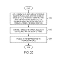
- FIG. 20 there is shown a flowchart of one example method of operating a polarized electromagnetic actuator.
- a current is applied to each coil in the actuator.
- the current flows through each coil in a given direction to produce a magnetic flux in a first direction.
- the magnetic flux of the coil can increase a magnetic flux of at least one permanent magnet included in the actuator in the first direction to produce a force in the first direction.
- the force can produce motion in the at least the first direction.
- the amount of current flowing through the coil can be controlled to controllably vary the amount of force applied to a movable armature and to produce motion in the direction of the increased magnetic flux associated with the at least one permanent magnet (block 2002 ).
- the amount of current passing through the coil can be increased or decreased depending on the desired amount of force and the desired direction of movement.
- a haptic response can be produced based on the force produced by the polarized electromagnetic actuator.
- the haptic response can be in one direction and/or in multiple directions based on the direction of the current passing through each coil. Additionally or alternatively, the magnitude of the haptic response can be controlled based on the amount of current passing through each coil.
- block 2002 can be omitted.
- block 2004 can be performed before block 2002 .
- Embodiments of polarized electromagnetic actuators can be included in any type of device.
- acoustical systems such as headphones and speakers
- computing systems haptic systems, and robotic devices can include one or more polarized electromagnetic actuators.
- Haptic systems can be included in computing devices, digital media players, input devices such as buttons, trackpads, and scroll wheels, smart telephones, and other portable user electronic devices to provide tactile feedback to a user.
- the tactile feedback can take the form of an applied force, a vibration, or a motion.
- One or more polarized electromagnetic actuators can be included in a haptic system to enable the tactile feedback (e.g., motion) that is applied to the user.
- FIG. 21 is a front perspective view of an electronic device that can include one or more polarized electromagnetic actuators.
- the polarized electromagnetic actuators can be used, for example, to provide haptic feedback to a user.
- the electronic device 2100 can be a laptop or netbook computer that includes a display 2102 , a keyboard 2104 , and a touch device 2106 , shown in the illustrated embodiment as a trackpad.
- An enclosure 2108 can form an outer surface or partial outer surface and protective case for the internal components of the electronic device 2100 , and may at least partially surround the display 2102 , the keyboard 2104 , and the trackpad 2106 .
- the enclosure 2108 can be formed of one or more components operably connected together, such as a front piece and a back piece.
- the display 2102 is configured to display a visual output for the electronic device 2100 .
- the display 2102 can be implemented with any suitable display, including, but not limited to, a liquid crystal display (LCD), an organic light-emitting display (OLED), or organic electro-luminescence (OEL) display.
- LCD liquid crystal display
- OLED organic light-emitting display
- OEL organic electro-luminescence
- the keyboard 2104 includes multiple keys that can be used to enter data into an application or program, or to interact with one or more viewable objects on the display 2102 .
- the keyboard 2104 can include alphanumeric or character keys, navigation keys, function keys, and command keys.
- the keyboard can be configured as a QWERTY keyboard with additional keys such as a numerical keypad, function keys, directional arrow keys, and other command keys such as control, escape, insert, page up, page down, and delete.
- the trackpad 2106 can be used to interact with one or more viewable objects on the display 2102 .
- the trackpad 2106 can be used to move a cursor or to select a file or program (represented by an icon) shown on the display.
- the trackpad 2106 can use any type of sensing technology to detect an object, such as a finger or a conductive stylus, near or on the surface of the trackpad 2106 .
- the trackpad 2106 can include a capacitive sensing system that detects touch through capacitive changes at capacitive sensors.
- the trackpad 2106 can include one or more polarized electromagnetic actuators to provide haptic feedback to a user.
- a cross-section view of the trackpad 2106 along line 17 - 17 can include the cross-section view of the polarized electromagnetic actuator shown in FIG. 17 .
- the top surface of the trackpad 2106 can be the top surface of the movable armature 1710 , and the actuator can be included under the top surface of the trackpad 2106 .
- one or more polarized electromagnetic actuators included in the trackpad 2106 can be implemented as one or more actuators shown in FIGS. 3, 7, 8, 11-16 , and FIG. 18 .
- the polarized electromagnetic actuators can be positioned in the same direction or in different directions. For example, one polarized electromagnetic actuator can provide motion along an x-axis while a second polarized electromagnetic actuator provides motion along a y-axis.
- one or more keys in the keyboard 2104 can include a polarized electromagnetic actuator or actuators.
- the top surface of a key in the keyboard can be the top surface of the movable armature, and the actuator can be included under the top surface of the key.
- the electronic device 2200 is a smart telephone that includes an enclosure 2202 surrounding a display 2204 and one or more buttons 2206 or input devices.
- the enclosure 2202 can be similar to the enclosure described in conjunction with FIG. 21 , but may vary in form factor and function.
- the display 2204 can be implemented with any suitable display, including, but not limited to, a multi-touch touchscreen display that uses liquid crystal display (LCD) technology, organic light-emitting display (OLED) technology, or organic electro luminescence (OEL) technology.
- the multi-touch touchscreen display can include any suitable type of touch sensing technology, including, but not limited to, capacitive touch technology, ultrasound touch technology, and resistive touch technology.
- the button 2206 can take the form of a home button, which may be a mechanical button, a soft button (e.g., a button that does not physically move but still accepts inputs), an icon or image on a display, and so on. Further, in some embodiments, the button 2206 can be integrated as part of a cover glass of the electronic device.
- the button 2206 can include one or more polarized electromagnetic actuators to provide haptic feedback to the user.
- a cross-section view of the button 2206 along line 17 - 17 can include the cross-section view of the polarized electromagnetic actuator shown in FIG. 17 .
- the top surface of the button can be the top surface of the movable armature 1710 , and the actuator can be included under the top surface of the button 2206 .
- one or more polarized electromagnetic actuators included in the button 2206 can be implemented as one or more actuators shown in FIGS. 3, 7, 8, 11-16 , and FIG. 18 .
- the polarized electromagnetic actuators can be positioned in the same direction or in different directions. For example, one polarized electromagnetic actuator can provide motion along an x-axis while a second polarized electromagnetic actuator provides motion along a y-axis.
- a portion of the enclosure 2202 and/or the display 2204 can include one or more polarized electromagnetic actuators to provide haptic feedback to the user.
- the exterior surface of the enclosure and/or the display can be the top surface of the movable armature with the actuator included under the top surface of the enclosure and/or display.
- the polarized electromagnetic actuators can be positioned in the same direction or in different directions.
Abstract
A polarized electromagnetic actuator includes a movable armature, a stator, and at least one coil wrapped around the stator. At least one permanent magnet is disposed over the stator. When a current is applied to the at least one coil, the at least one coil is configured to reduce a magnetic flux of at least one permanent magnet in one direction and increase a magnetic flux of at least one permanent magnet in another direction. The movable armature moves in the direction of the increased magnetic flux.
Description
This application is a 35 U.S.C. § 371 application of PCT/US2013/062449, filed on Sep. 27, 2013, and entitled “Polarized Magnetic Actuators for Haptic Response,” which is incorporated by reference as if fully disclosed herein.
The present invention relates to actuators, and more particularly to electromagnetic actuators that include one or more permanent magnets.
An actuator is a device that converts one form of energy into some type of motion. There are several different types of actuators, including pneumatic, hydraulic, electrical, mechanical, and electromagnetic. An electromagnetic actuator provides mechanical motion in response to an electrical stimulus. The electromagnetic actuator typically includes a coil and a movable armature made of a ferromagnetic material. A magnetic field is produced around the coil when current flows through the coil. The magnetic field applies a force to the armature to move the armature in the direction of the magnetic field.
Some electromagnetic actuators are limited in the type of force that can be applied to an armature. For example, an armature can be pushed but not pulled. Additionally, some electromagnetic actuators may produce a negligible amount of force when a small amount of current is applied to the coil. And in some devices or components, such as in portable electronic devices or components used in portable electronic devices, it can be challenging to construct an electromagnetic actuator that has both a reduced size and an ability to generate a desired amount of force.
In one aspect, a polarized electromagnetic actuator can include a movable armature and a stator, a first coil and a second coil wrapped around the stator, and a permanent magnet disposed over the stator. The moveable armature is spaced apart from the stator. The first and second coils produce a first magnetic flux in a first direction when a current is applied to the first and second coils. The first magnetic flux reduces a second magnetic flux of the permanent magnet in a first direction and increases the second magnetic flux in a second direction to produce motion in the movable armature in the second direction. The amount of force applied to the movable armature can be controlled by controlling the amount of current flowing through the first and second coils. Additionally, the direction of the force applied to the movable armature is dependent upon the direction of the current passing through the first and second coils.
In another aspect, a polarized electromagnetic actuator can include a movable armature and a stator having two tines extending out from the stator. The movable armature is spaced apart from the two tines of the stator. A first coil is wrapped around one tine and a second coil is wrapped around the other tine. At least one permanent magnet is disposed over the stator between the two tines. The first and second coils produce a first magnetic flux in a first direction when a current is applied to the first and second coils. The first magnetic flux reduces a second magnetic flux of the permanent magnet in a first direction and increases the second magnetic flux in a second direction to produce motion in the movable armature in the second direction. The amount of force applied to the movable armature can be controlled by controlling the amount of current flowing through the first and second coils. Additionally, the direction of the force applied to the movable armature is dependent upon the direction of the current passing through the first and second coils.
In yet another aspect, a polarized electromagnetic actuator can include a stator including two tines extending out from the stator and a coil wrapped around the stator between the two tines. A movable armature can include a first arm disposed over one tine of the stator, a second arm disposed over the other tine of the stator, and a body disposed between the two tines. A first permanent magnet can be positioned between the first arm of the armature and one tine of the stator, and a second permanent magnet can be positioned between the second arm of the armature and the other tine of the stator. For example, in one embodiment, the first permanent magnet is attached to the first arm of the armature and disposed over one tine of the stator and the second permanent magnet is attached to the second arm of the armature and disposed over the other tine of the stator. In another embodiment, the first permanent magnet is attached to one tine of the stator and the second permanent magnet is attached to the other tine of the stator. The coil produces a first magnetic flux when a current is applied to the coil and the magnetic flux of the coil can increase a magnetic flux of one permanent magnet to produce motion in the movable armature in a direction of the increased magnetic flux.
In another aspect, a polarized electromagnetic actuator can include a stator including two tines extending out from the stator and a coil wrapped around the stator between the two tines. A movable armature can include a first arm disposed over one tine and of the stator, a second arm disposed under the other tine of the stator, and a body disposed between the two tines. A first permanent magnet can be attached to one tine of the stator and a second permanent magnet can be attached to the other tine of the stator. The coil produces a first magnetic flux when a current is applied to the coil and the magnetic flux of the coil can increase a magnetic flux of one permanent magnet to produce motion in the movable armature in a direction of the increased magnetic flux.
In another aspect, a method for providing a polarized electromagnetic actuator includes providing a movable armature and a stator, providing at least one coil wrapped around the stator, and providing at least one permanent magnet over the stator. The at least one coil is configured to reduce a magnetic flux of at least one permanent magnet in one direction and increase a magnetic flux of at least one permanent magnet in another direction when a current is applied to the at least one coil to move the movable armature in the direction of the increased magnetic flux.
And in yet another aspect, a polarized electromagnetic actuator includes a movable armature, a stator, at least one coil wrapped around the stator, and at least one permanent magnet disposed over the stator. A method for operating the polarized electromagnetic actuator includes applying a current to the at least one coil to produce a first magnetic flux that reduces a second magnetic flux of at least one permanent magnet in a first direction and increases the second magnetic flux of at least one permanent magnet in a second direction to move the movable armature in the second direction. The current to the at least one coil can be controllably varied to adjust a force applied to the movable armature.
Embodiments are better understood with reference to the following drawings. The elements of the drawings are not necessarily to scale relative to each other. Identical reference numerals have been used, where possible, to designate identical features that are common to the figures.
Embodiments described herein provide a polarized electromagnetic actuator that includes a movable armature spaced apart from a stator. One or more permanent magnets can be disposed over the stator, and one or more coils can be wrapped around the stator. The polarized electromagnetic actuator can generate a greater amount of force by increasing a magnetic flux of a permanent magnet using a magnetic flux produced by one or more coils. For example, in one embodiment, a permanent magnet provides a background magnetic field and flux that are distributed evenly through an armature and a stator. Two coils wrapped around either the stator or the armature produces a magnetic field and flux in a given direction when a current is applied to the coil. The direction of the coil magnetic flux is dependent upon the direction of the current flowing through the coils. The magnetic flux of the coil reduces or cancels the magnetic flux of the permanent magnet in one direction and increases the magnetic flux of the permanent magnet in another direction. The increased magnetic flux of the permanent magnet applies a force to the armature to move the armature in a direction of the increased magnetic flux.
The amount of force applied to the armature can be controlled by controlling the current flowing through the coil or coils. The applied force can be increased by increasing the current, or the amount of force can be decreased by decreasing the current. In some embodiments, the magnetic flux of the coil or coils completely cancels a magnetic flux of a permanent magnet in a first direction. In some embodiments, the amount of force applied to the armature can increase or decrease linearly by varying the current applied to the coil(s).
In some embodiments, the magnetic forces can cause a destabilizing force on the armature similar to a negative spring. This destabilizing force causes the armature to be attracted to one of the tines. One or more stabilizing elements can be included with the polarized electromagnetic actuators to stabilize the armature when a current is not applied to the coil or coils. The stabilizing element or elements can compensate for the destabilizing force. Examples of stabilizing elements include, but are not limited to, springs, flexible structures, or gel packs or disks that can be positioned between the armature and the stator to assist in stabilizing the armature.
Embodiments of polarized electromagnetic actuators can be included in any type of device. For example, acoustical systems such as headphones and speakers, computing systems, haptic systems, and robotic devices can include one or more polarized electromagnetic actuators. Haptic systems can be included in computing devices, digital media players, input devices such as buttons, trackpads, and scroll wheels, smart telephones, and other portable electronic devices to provide tactile feedback to a user. For example, the tactile feedback can take the form of an applied force, a vibration, or a motion. One or more polarized electromagnetic actuators can be included in a haptic system to enable the tactile feedback (e.g., motion) that is applied to the user.
For example, the top surface of a trackpad can be disposed over the top surface of a movable armature of a polarized electromagnetic actuator, or the top surface of the trackpad can be the top surface of the movable armature. The actuator can be included under the top surface of the trackpad. One or more polarized electromagnetic actuators can be included in the trackpad. The polarized electromagnetic actuators can be positioned in the same direction or in different directions. For example, one polarized electromagnetic actuator can provide motion along an x-axis while a second polarized electromagnetic actuator provides motion along a y-axis.
Other embodiments switch the roles of the armature and the stator so that a polarized electromagnetic actuator includes an armature spaced apart from a movable stator. One or more permanent magnets can be disposed over the armature, and one or more coils can be wrapped around the armature. A magnetic field and flux are produced in a given direction when a current is applied to one or more coils. The direction of the coil magnetic flux is dependent upon the direction of the current flowing through the coils. The magnetic flux of the coil reduces or cancels the magnetic flux of the permanent magnet in one direction and increases the magnetic flux of the permanent magnet in another direction. Similarly, one or more stabilizing elements can be included with the polarized electromagnetic actuators to stabilize the armature when a current is not applied to the coil or coils.
Referring now to FIG. 1 , there is shown a simplified illustration of one example of a prior art electromagnetic actuator. The actuator 100 includes a stator 102 having two tines 104, 106 that extend out from the stator 102 to form a “U” shaped region. A solenoid or helical coil 108, 110 is wrapped around each tine 104, 106. A movable armature 112 is arranged in a spaced-apart relationship to the tines 104, 106 of the stator 102. The stator 102 and the movable armature 112 can be made of any suitable ferromagnetic material, compound, or alloy, such as steel, iron, and nickel.
Each respective coil and tine forms an electromagnet. An electromagnet is a type of magnet in which a magnetic field is produced by a flow of electric current. The magnetic field disappears when the current is turned off. In the embodiment shown in FIG. 1 , a magnetic field B and a magnetic flux ϕ are produced when current flows through the coils 108, 110. In FIG. 1 , the magnetic field B is represented by one magnetic field arrow and the magnetic flux ϕ is represented by one flux line.
The force produced by the magnetic field B can be controlled by controlling the amount of electric current (I) flowing through the coils 108, 110 in that the force varies according to the equation I2. The force is attractive and causes the armature 112 to be pulled downwards towards both tines 104, 106 (movement represented by arrow 114). Assuming the core is not saturated and does not contribute significantly to the overall reluctance, and assuming no significant fringing fields in the air gap g, the force (F) exerted by the electromagnets (i.e., tine 104 and coil 108; tine 106 and coil 110) can be determined by the following equation,
where μ0 is the permeability of free space or air, V is the applied voltage, D is the wire diameter (total), wc is the core width of the coil (see
The force (F) divided by the power (P) for the electromagnets can be calculated by
where μ0 is the permeability of free space or air, Lc is the length of the coil, wc is the core width of the coil, tc is the core thickness of the coil, ta is the thickness of the wire coil, ρ is the effective resistivity of the coil, g is the gap between the
One limitation to the actuator 100 is that the force can produce motion in only one direction, such that the armature 112 can only be pulled down toward the tines 104, 106. Additionally, the overall efficiency for the actuator 100 can be low. For example, in some embodiments, the overall efficiency of the actuator can be 1.3%. One reason for the reduced efficient is saturation, but the non-linear effects of the gap g can somewhat offset the reduced efficiency in some embodiments.
Referring now to FIG. 2 , there is shown a simplified illustration of another example of a prior art electromagnetic actuator. The actuator 200 includes a movable armature 202 and a stator 204 held in a spaced-apart relationship to the armature 202. The stator 204 includes two tines 206, 208 extending out such that the stator 204 is formed into a “U” shape. A helical coil 210 is wrapped around the stator 204 between the tines 206, 208. When a current flows through the coil 210, a magnetic flux ϕC is created that travels through the movable armature 202 and around the stator 204 through the tines 206, 208. The direction of travel of the coil magnetic flux ϕC depends on the direction of the current passing through the coil 210.
A magnet 212 is disposed between the two tines 206, 208 below the armature 202. The magnet 212 typically has a relatively small width W. The magnet 212 is polarized with two north poles on the outer edges of the magnet and a single south pole in the center. The flux from the south pole traverses a small air gap to the armature 202 and then propagates through the armature to the upper corner of the stator 204 and back through the magnet 212. The flux from the coil 210 interacts with the flux from the magnet 212 to produce a net torque on the armature. Relay contact arms (not shown) act as flexures that stabilize the negative spring constant of the magnetic field of the magnet 212.
The double pole magnet 212 can be difficult to produce. Additionally, the illustrated actuator typically works well for a relay, but the force produced by the actuator is limited by the width W of the magnet 212. It can be desirable to use an actuator that can produce larger forces in other types of applications and/or devices. By way of example only, other embodiments can use an actuator that creates a more powerful force that is able to produce a haptic response in a device, such as in a trackpad or other similar device.
Embodiments described herein provide a polarized electromagnetic actuator that is more efficient, can produce a greater amount of force for the same applied current, and can produce a controllable motion in two directions (e.g., push and pull). FIG. 3 is a simplified illustration of a first example of a polarized electromagnetic actuator. The actuator 300 includes a stator 302 with two tines 304, 306 extending out to form a “U” shaped region of the stator 302. A helical coil 308, 310 is wrapped around each tine 304, 306 and a permanent magnet 312 is positioned between the tines 304, 306. A movable armature 314 is arranged in a spaced-apart relationship to the tines of the stator 302 and disposed over a pivot 316.
In the illustrated embodiment, the stator 302 and the movable armature 314 can be made of any suitable ferromagnetic material, compound, or alloy, such as steel, iron, and nickel. The permanent magnet 312 can be any suitable type of permanent magnet, including, but not limited to, a neodymium (NdFeB) magnet. A ferromagnetic material is a material that can be magnetized. Unlike a ferromagnetic material, a permanent magnet is made of a magnetized material that produces a persistent magnetic field. In FIG. 3 , the permanent magnet 312 produces a magnetic field B that is distributed evenly through each stator tine 304, 306 when the gaps g1 and g2 are equal. The magnetic flux ϕM1, ϕM2 associated with the permanent magnet 312 provides a background magnetic flux traveling through the movable armature 314 and the stator 302 (including the tines 304, 306). When a current flows through the coils 308, 310, a magnetic flux ϕC is created that travels through the movable armature 314 and around the stator 302 through the tines 304, 306, but substantially not through the permanent magnet 312. The direction of travel of the coil magnetic flux ϕC depends on the direction of the current passing through the coils 308, 310.
The magnetic flux ϕC produced by the coils 308, 310 interacts with the magnetic flux ϕM1, ϕM2 of the permanent magnet to reduce or cancel the magnetic flux in one direction (ϕM1 or ϕM2) and increase the magnetic flux in the other direction. Motion is produced in the movable armature 314 in the direction of the increased magnetic flux (ϕM1 or ϕM2). For example, in the illustrated embodiment, the coil magnetic flux ϕC is traveling in a direction that opposes the direction of the magnetic flux ϕM1, thereby reducing or canceling the magnetic flux ϕM1. Concurrently, the coil magnetic flux ϕC is traveling in the same direction as the direction of the magnetic flux ϕM2, thereby increasing the magnetic flux ϕM2. The armature 314 moves up and down like a teeter-totter based on the force applied to the armature (movement represented by arrow 318). The movable armature 314 can be pulled toward a respective tine or pushed away from a respective tine depending on the direction of the current through the coils 308, 310. Additionally, the amount of force applied to the armature can be controlled by controlling the amount of current applied to the coils 308, 310.
Ampere's Law ∇×H=J and Maxwell's Equation ∇·B=0 can be used to analyze the illustrated actuator 300. Note that the following analysis assumes the core does not saturate and that no fringing fields are present in the gaps g1 and g2.
∇×H=J: H 1 g 1 −H m L m =NI 1; andEquation 3
H m L m −H 2 g 2 =NI 2 Equation 4
∇·B=0: B 1 A 1 +B m A m +B 2 A 2=0Equation 5
where Lm is the length of thepermanent magnet 312, N is the number of turns in each coil 308, 310, and H1, H2, and Hm are the H fields (magnetic strength) associated with the magnetic fields B1, B2, and Bm, respectively. Another equation included in the analysis is the relationship between the magnetic field B and the H field in the permanent magnet, also known as the demagnetization curve. Magnet suppliers typically provide a demagnetization curve for each of the materials used in the permanent magnets. Typically, the relationship between B and H is linear and can be approximated as follows,
B m =B r+μ0 H m Equation 6
where Br is the remanent magnetization of the permanent magnet (e.g., ˜1.2 T). Solvingequations 3 through 6, the magnetic force B1 and B2 can be determined by
∇×H=J: H 1 g 1 −H m L m =NI 1; and
H m L m −H 2 g 2 =NI 2 Equation 4
∇·B=0: B 1 A 1 +B m A m +B 2 A 2=0
where Lm is the length of the
B m =B r+μ0 H m Equation 6
where Br is the remanent magnetization of the permanent magnet (e.g., ˜1.2 T). Solving
As described earlier, the magnetic flux ϕC produced by the coils 308, 310 interacts with the magnetic flux ϕM1, ϕM2 of the permanent magnet to reduce or cancel one magnetic flux (ϕM1 or ϕM2) and increase the other magnetic flux. When the magnetic flux ϕC cancels a magnetic flux in one direction (ϕM1 or ϕM2) completely, the magnetic field of the coil Bcoil equals the magnetic field in the permanent magnet Bmagnet, and the force is increased. By way of example only, in the illustrated embodiment, when the magnetic field of the coil Bcoil equals the magnetic field in the permanent magnet Bmagnet, the force produced by the left-hand side 320 of the actuator 300 can be determined by
Also, when the magnetic field of the coil Bcoil equals the magnetic field in the permanent magnet Bmagnet, the force produced by the right-
In comparison, the amount of force generated by the left-
Thus, the actuator 300 in FIG. 3 can generate more force than the actuator 100 in FIG. 1 . The actuator 300 in FIG. 3 can produce a magnetic force Bmagnet>Bcoil, which means a smaller Bcoil can be produced to obtain the same amount of force as the actuator 100 in FIG. 1 . In the event that the coil produces the same size field as the permanent magnet (Bcoil=Bmagnet), then equations 10 and 11 above demonstrate that the polarized actuator produces twice the force of a conventional actuator. In some situations, the field produced by the coil is less than the field produced by the permanent magnet, in which case the polarized actuator produces more than twice the force of a conventional actuator.
Similarly, the total force produced by the magnetic fields varies linearly with the applied current. FIG. 5 illustrates an example graph of the forces varying with an applied current for the polarized electromagnetic actuator shown in FIG. 3 . In the illustrated embodiment, the force F1 produced by the magnetic field B1 (plot 500) increases with the current applied to the coils while the force F2 produced by the magnetic field B2 (plot 502) decreases with the applied current. The resulting total force F1-F2 increases linearly as the current applied to the coils 308, 310 increases from −2 amps to +2 amps, as shown in plot 504.
The resulting total force F1-F2 can also vary linearly with armature position. As shown in FIG. 6 , as the gap g2 increases, the force F2 produced by the magnetic field B2 decreases. Since the armature 314 pivots around a point central to the two tines 304 and 306, increasing gap g2 causes gap g1 to decrease. As g1 decreases the force F1 produced by the magnetic field B1 increases. The net force F1-F2 thus increases with increasing gap g2. Detailed modeling of the magnetic fields B1 and B2 demonstrate that this increase in net force is approximately linear with g2.
The polarized electromagnetic actuator 300 can have a higher overall efficiency than the actuator 100 of FIG. 1 . As described above, the actuator 300 can generate more force at the same current compared to the actuator 100 in FIG. 1 . Moreover, the total force varies linearly with the applied current for the actuator 300, so the actuator 300 provides linear control of the total force. In comparison, the total force of actuator 100 (FIG. 1 ) is approximately equal to the square of the current.
Additionally, including the permanent magnet 312 in the actuator 300 can reduce power consumption of the actuator 300. The force is driven by the magnetic field from the permanent magnet 312. So a fairly substantial force can be generated by the actuator 300 even when the amount of current flowing through the coils 308, 310 is relatively small. With the prior art actuator 100 shown in FIG. 1 , a small or negligible amount of force is generated when a small amount of current is flowing through the coils 108, 110.
The permanent magnet 312 can be easier to manufacture compared to the magnet 212 shown in FIG. 2 because the permanent magnet 312 has a single set of north and south poles compared to the magnet 212 that has a single south pole and two north poles. Additionally, the permanent magnet 312 can be relatively shorter and wider than the relatively thinner and longer magnet 212. The shorter and wider permanent magnet 312 may provide improved volume efficiency compared to the magnet 212.
Referring now to FIG. 7 , there is shown a simplified illustration of a second example of a polarized electromagnetic actuator. The actuator 700 includes many of the same elements shown in FIG. 3 , and as such these elements will not be described in more detail herein. A first permanent magnet 702 is positioned between the tine 304 and a pivot 704. A second permanent magnet 706 is disposed between the pivot 704 and the tine 306. The pivot 704 can provide a restoring force to the armature 314 so the armature naturally re-centers itself when the current in the coils 308, 310 is turned off.
Like the embodiment shown in FIG. 3 , the magnetic flux ϕC produced by the coils 308, 310 interacts with the magnetic flux ϕM1, ϕM2 of the permanent magnets to reduce or cancel one magnetic flux in one direction ϕM1 or ϕM2) and increase the magnetic flux in the other direction. Motion is produced in the direction of the increased magnetic flux.
For example, in the illustrated embodiment, the coil magnetic flux ϕC is traveling in a direction that opposes the direction of the magnetic flux ϕM2, thereby reducing or canceling the magnetic flux ϕM2. Concurrently, the coil magnetic flux ϕC is traveling in the same direction as the direction of the magnetic flux ϕM1, thereby increasing the magnetic flux ϕM1. The armature 314 moves up and down (e.g., like a teeter-totter) based on the force applied to the movable armature. The movable armature 314 can be pulled toward a respective tine or pushed away from a respective tine depending on the direction of the current through the coils 308, 310. Additionally, the amount of applied force can be controlled by controlling the amount of current flowing through the coils 308, 310.
In some embodiments, the movable armature can be in an unstable equilibrium when a current is not applied to the coils. In such embodiments, one or more stabilizing elements can stabilize the armature using a restoring force to prevent the armature from moving to one of the two contacts. In FIG. 7 , the pivot 704 can provide a restoring force that stabilizes the movable armature 314. With the actuator 300 shown in FIG. 3 , the armature 314 can be stabilized with one or more springs or gel disks placed between the armature 314 and the stator 302. Other embodiments can design the armature 314 to saturate at large fields and limit the growth of the force, or the armature can be designed to move in only one direction in the absence of a current through the coils, and a stop can be provided in the one direction of movement. Alternatively, the stator can be designed to include an additional non-force generating flux path.
With respect to the actuators shown in FIGS. 3 and 7 , one method for providing a restoring force to the actuators 300, 700 is illustrated in FIG. 8 . Stabilizing elements 800, such as C-springs, are provided around the ends of the movable armature 314 and the protrusions 802 of the stator 302 to restrict or limit the movement of the armature 314. By way of example only, the space between the armature 314 and the tines 304, 306 can be 300 microns. The movable armature 314 can therefore only move 300 microns in any one direction when the stabilizing elements 800 are placed over the ends of the actuator 700.
Although the FIG. 7 actuator 700 is used to depict the stabilizing elements 800, those skilled in the art will recognize that the stabilizing elements 800 can be used with the actuator 300 shown in FIG. 3 .
In contrast, the stabilizing elements 800 can limit the applied force within the same armature displacement. When a current is not applied to the coils 308, 310, plot 1002 of FIG. 10 represents the applied force as a function of armature displacement when 0 Aturns is applied to each coil 308, 310. As shown, with the stabilizing elements 800, the applied force ranges between approximately −1 N and +1 N as the armature 314 is displaced between −150 and +150 microns. The addition of the stabilizing elements 800 causes the force to have a negative slope as it passes through the origin. Therefore, the actuator is stable at zero displacement. And the applied force ranges approximately between +9 and +7 when 100 Aturns is applied to each coil 308, 310 (see plot 1000).
Referring now to FIG. 11 , there is shown a simplified illustration of a third example of a polarized electromagnetic actuator. The actuator 1100 includes a stator 1102 with two tines 1104, 1106 extending out to form into a “U” shaped region of the stator 1102. A helical coil 1108, 1110 is wrapped around each tine 1104, 1106 and a permanent magnet 1112 is positioned in a spaced-apart relationship to the stator 1102 and the permanent magnet 1112. In the illustrated embodiment, the movable armature 1114 is disposed over the permanent magnet 1112 and within the “U” shaped region between the tines 1104, 1106.
The permanent magnet 1112 can produce a magnetic field B that is distributed evenly through each stator tine 1104, 1106. The magnetic flux ϕM1, ϕM2 associated with the permanent magnet 1112 provides a background magnetic flux traveling from the permanent magnet 1112 through the armature 1114, the stator 1102 (including the tines 1104, 1106), and back to the permanent magnet 1112. A magnetic flux ϕC is produced when a current is applied to the coils 1108, 1110. The coil magnetic flux ϕC travels through the armature 1114 and around the stator 1102 through the tines 1104, 1106, but largely not through the permanent magnet 1112. The direction of travel of the coil magnetic flux ϕC depends on the direction of the current passing through the coils 1108, 1110.
The magnetic flux produced by the coils 1108, 1110 reduces or cancels the magnetic flux in a first direction and increases the magnetic flux in a second direction of the permanent magnet. Motion is produced in the armature in the direction of the increased magnetic flux. The armature 1114 moves left and right based on the force applied to the armature (movement represented by arrow 1116). The movable armature 1114 can be pulled toward a respective tine or pushed away from a respective tine depending on the direction of the current through the coils 1108, 1110. Additionally, the amount of force applied to the movable armature 1114 can be controlled by controlling the amount of current applied to the coils 1108, 1110.
Referring now to FIG. 14 , there is shown a simplified illustration of a fourth example of a polarized electromagnetic actuator. The actuator 1400 includes a rectangular-shaped stator 1402 and a movable armature 1404 held in a spaced-apart relationship to the stator 1402. The movable armature 1404 includes two tines 1406, 1408 extending out to form a “U” shaped region of the armature 1404. A first helical coil 1410 is wrapped around one end of the stator 1402 between the tines 1406, 1408 and a second helical coil 1412 is wrapped around the other end of the stator 1402 between the tines 1406, 1408. A permanent magnet 1414 is positioned over the stator 1402 between the two coils 1410, 1412.
The permanent magnet 1414 produces a magnetic flux ϕM1, ϕM2 that provides a background magnetic flux traveling through the stator 1402 and the movable armature 1404 (including the tines 1406, 1408). A magnetic flux ϕC is produced by the first and second coils 1410, 1412 when a current is applied to the coils 1410, 1412. The coil magnetic flux ϕC travels through the armature 1404 (including the tines 1406, 1408) and around the stator 1402 (but largely not through the permanent magnet 1414). The direction of travel of the coil magnetic flux ϕC depends on the direction of the current passing through the coils 1410, 1412.
The coil magnetic flux ϕC interacts with a respective magnetic flux ϕM1 or ϕM2) of the permanent magnet to reduce or cancel the magnetic flux in one direction and increase the magnetic flux in the other direction. For example, in the illustrated embodiment, the coil magnetic flux ϕC is traveling in a direction that opposes the direction of the magnetic flux ϕM1, thereby reducing or canceling the magnetic flux ϕM1. Concurrently, the coil magnetic flux ϕC is traveling in the same direction as the direction of the magnetic flux ϕM2, thereby increasing the magnetic flux ϕM2. The increase in the magnetic flux ϕM2 by the magnetic flux ϕC2 increases the force. The armature 1404 moves in the direction of the increased magnetic flux ϕM2 based on the force applied to the movable armature.
In the embodiments of FIGS. 3, 7, 8, and 11-14 , the coil magnetic flux largely does not pass through the permanent magnet or magnets. This is due to the fact that the permanent magnet(s) appear or act like an air gap when the coil(s) produces a magnetic flux. Since the thickness of the permanent magnets can be much larger than the thicknesses of the air gaps g1 and g2, the path through the magnet is relatively high reluctance and a very small fraction of the coil flux traverses the magnet. In a fifth example of a polarized electromagnetic actuator shown in FIG. 15 , the coil magnetic flux does not pass through the permanent magnets and the magnetic fluxes of the permanent magnets does not travel through the coil.
The actuator 1500 includes a stator 1502 with tines 1504, 1506 extending out to form a “U” shaped region of the stator. A helical coil 1508 is wrapped around the stator 1502 between the two tines 1504, 1506. A first permanent magnet 1510 is positioned over the tine 1504 and a second permanent magnet 1512 is disposed over the tine 1506. A movable armature 1514 can be formed in a “T” shape with the arms 1516, 1518 of the T-shaped armature 1514 disposed over the permanent magnet 1510, 1512, respectively. The body of the T-shaped armature 1514 is positioned over the coil 1508 within the “U” shaped region between the tines 1504, 1506. The movable armature 1514 is held in a spaced-apart relationship to the stator 1502 and the permanent magnets 1510, 1512.
The permanent magnet 1510 produces a magnetic flux ϕM1 and the permanent magnet 1512 produces a magnetic flux ϕM2. The magnetic fluxes ϕM1, ϕM2 provide a background magnetic flux around respective permanent magnets 1510, 1512 and through the movable armature 1514 (but not through the coil 1508). Additionally, a magnetic flux ϕC is produced when a current is applied to the coil 1508. The coil magnetic flux ϕC travels through the body of the T-shaped armature 1514 and around the stator 1502 and tines 1504, 1506, but not (or largely not) through the permanent magnets 1510, 1512. As with the other embodiments, the direction of travel of the coil magnetic flux ϕC depends on the direction of the current passing through the coil 1508.
The magnetic flux ϕC produced by the coil 1508 interacts with the magnetic flux ϕM1, ϕM2 of the permanent magnets 1510, 1512 to reduce or cancel one magnetic flux (ϕM1, or ϕM2) and increase the other magnetic flux. Motion is produced in the movable armature 1514 in the direction of the increased magnetic flux. The armature 1514 moves in a left direction or in a right direction based on the direction of the increased magnetic flux (movement depicted by arrow 1520). For example, in the illustrated embodiment, the coil magnetic flux ϕC is traveling in a direction that opposes the direction of the magnetic flux ϕM1, thereby reducing or canceling the magnetic flux ϕM1. Concurrently, the coil magnetic flux ϕC is traveling in the same direction as the direction of the magnetic flux ϕM2, thereby increasing the magnetic flux ϕM2. The increase in the magnetic flux ϕM2 by the magnetic flux ϕC increases the amount of force applied to the movable armature 1514.
As previously described, the armature 1514 moves left or right based on the force applied to the armature (movement represented by arrow 1520). The movable armature 1514 can be pulled toward a respective tine or pushed away from a respective tine depending on the direction of the current through the coil 1508. Additionally, the amount of force applied to the movable armature 1514 can be controlled by controlling the amount of current applied to the coil 1508. Since force is approximately equal to the square of the magnetic field (F˜B2), the increase in the magnetic flux ϕM2 by the coil magnetic flux ϕC increases the force. With the actuator 1500. F˜B2 can become F=4BmBc. Thus, the force is linear in applied current.
A polarized electromagnetic actuator can be thinner in height (z direction) than other electromagnetic actuators when the magnetic flux from a coil does not pass through a permanent magnet and the magnetic flux from the permanent magnet(s) does not travel through the coil. The material in which a coil surrounds can be thinned to account for the diameter of the coil. And in some embodiments, it is desirable to have the field going through the coil be as small as possible. So to avoid saturation, the actuator is designed so the magnetic flux from the permanent magnet does not pass through the coil since there may not be a sufficient amount of material in the coil to carry the magnetic flux from both the coil and the permanent magnet(s).
Referring now to FIG. 17 , there is shown a simplified illustration of a sixth example of a polarized electromagnetic actuator. Like the embodiment shown in FIG. 15 , the coil magnetic flux does not pass through the permanent magnets and the magnetic fluxes of the permanent magnets does not travel through the coil.
The actuator 1700 includes a stator 1702 with two tines 1704, 1706 extending out from the stator 1702 to form a “U” shaped region of the stator 1702. A helical coil 1708 is wrapped around the stator 1702 between the two tines 1704, 1706. A movable armature 1710 can be formed in a “T” shape with the arms 1712, 1714 of the T-shaped armature 1710 disposed over the tines 1704, 1706, respectively. The body of the T-shaped armature 1710 is positioned over the coil 1708 within the “U” shaped region between the tines 1704, 1706. A first permanent magnet 1716 is attached to one arm 1714 and positioned over the tine 1704 and a second permanent magnet 1718 is attached to the other arm 1716 and disposed over the tine 1706. The movable armature 1710 and the permanent magnets 1716, 1718 are held in a spaced-apart relationship to the stator 1702.
The permanent magnet 1716 produces a magnetic flux ϕM1 and the permanent magnet 1718 produces a magnetic flux ϕM2. The magnetic fluxes ϕM1, ϕM2 provide a background magnetic flux around respective permanent magnets 1716, 1718, through the movable armature 1710, and through the tines 1704, 1706 (but not through the coil 1708). Additionally, a magnetic flux ϕC is produced when a current is applied to the coil 1708. The coil magnetic flux ϕC travels through the body of the T-shaped armature 1710 and around the stator 1702 and tines 1704, 1706, but not (or largely not) through the permanent magnets 1716, 1718. As with the other embodiments, the direction of travel of the coil magnetic flux ϕC depends on the direction of the current passing through the coil 1708.
The magnetic flux ϕC produced by the coil 1708 interacts with the magnetic flux ϕM1, ϕM2 of the permanent magnets 1716, 1718 to reduce or cancel one magnetic flux (ϕM1 or ϕM2) and increase the other magnetic flux. Motion is produced in the movable armature 1710 in the direction of the increased magnetic flux (motion represented by arrow 1720). The armature 1710 moves in a left direction or in a right direction based on the direction of the increased magnetic flux. For example, in the illustrated embodiment, the coil magnetic flux ϕC is traveling in a direction that opposes the direction of the magnetic flux ϕM2, thereby reducing or canceling the magnetic flux ϕM2. Concurrently, the coil magnetic flux ϕC is traveling in the same direction as the direction of the magnetic flux ϕM1, thereby increasing the magnetic flux ϕM1. The increase in the magnetic flux ϕM1 by the magnetic flux ϕC increases the amount of force applied to the movable armature 1710.
As previously described, the armature 1710 moves left or right based on the force applied to the armature. The movable armature 1710 can be pulled toward a respective tine or pushed away from a respective tine depending on the direction of the current through the coil 1708. In the illustrated embodiment, a first bending flexure 1722 is attached to the outer ends of the arm 1712 and the protrusion 1724 of the stator 1702. A second bending flexure 1726 is attached to the outer ends of the arm 1714 and the protrusion 1728 of the stator 1702. The bending flexures 1722, 1726 can limit the movement of the armature 1710. The bending flexures 1722, 1726 can act as stabilizing elements by counteracting the attraction between the permanent magnets 1716, 1718 and the stator 1702. The spring constants of the bending flexures 1722, 1726 can stabilize the armature 1710 in the center of its travel. Other embodiments can include a fewer or greater number of stabilizing elements.
A movable armature 1812 can include an arm 1814 that is positioned over the tine 1804 and another arm 1816 that is positioned under the overhang 1808 of the second tine 1806. The body of the armature 1812 is positioned over the coil 1810 between the tines 1804, 1806. A first permanent magnet 1818 is attached to the tine 1804 between the tine 1804 and armature 1812. A second permanent magnet 1820 is attached to the outer end of the overhang 1808 between the overhang 1808 and the armature 1812. The movable armature 1812 is held in a spaced-apart relationship to the stator 1802 and the permanent magnets 1818, 1820.
The permanent magnet 1818 produces a magnetic flux ϕM1 and the permanent magnet 1820 produces a magnetic flux ϕM2. The magnetic fluxes ϕM1, ϕM2 provide a background magnetic flux around respective permanent magnets 1818, 1820 through the movable armature 1812, through the tine 1804, and through the overhang 1808 (but not through the coil 1810). Additionally, a magnetic flux ϕC is produced when a current is applied to the coil 1810. The coil magnetic flux ϕC travels through the armature 1812 and around the stator 1802 and tines 1804, 1806, but not (or largely not) through the permanent magnets 1818, 1820. As with the other embodiments, the direction of travel of the coil magnetic flux ϕC depends on the direction of the current passing through the coil 1810.
The magnetic flux ϕC produced by the coil 1810 interacts with the magnetic flux ϕM1, ϕM2 of the permanent magnets 1818, 1820 to reduce or cancel one magnetic flux (ϕM1 or ϕM2) and increase the other magnetic flux. Motion is produced in the movable armature 1812 in the direction of the increased magnetic flux (motion represented by arrow 1822).
The movable armature and stator can have a desired shape and thickness based on the amount of force to be generated by the actuator. The movable armature, stator, coil, and permanent magnet of the actuator are then configured at block 1902 such that the field produced by the coil does not pass through the permanent magnet. The movable armature, stator, coil, and permanent magnet of the actuator can also be configured such that the field produced by the permanent magnet does not pass through the coil (block 1904). Block 1904 can be omitted in some embodiments.
The movable armature, stator, coil, and permanent magnet of the actuator are configured so that the magnetic flux of the coil ϕc increases the magnetic flux of the permanent magnet in one direction to produce motion in the direction of the increased magnetic flux (block 1906). Next, as shown in block 1908, one or more stabilizing elements are provided to stabilize the movable armature when a current is not applied to the coil.
Referring now to FIG. 20 , there is shown a flowchart of one example method of operating a polarized electromagnetic actuator. Initially, at block 2000 a current is applied to each coil in the actuator. The current flows through each coil in a given direction to produce a magnetic flux in a first direction. The magnetic flux of the coil can increase a magnetic flux of at least one permanent magnet included in the actuator in the first direction to produce a force in the first direction. The force can produce motion in the at least the first direction.
The amount of current flowing through the coil can be controlled to controllably vary the amount of force applied to a movable armature and to produce motion in the direction of the increased magnetic flux associated with the at least one permanent magnet (block 2002). The amount of current passing through the coil can be increased or decreased depending on the desired amount of force and the desired direction of movement.
Next, as shown in block 2004, a haptic response can be produced based on the force produced by the polarized electromagnetic actuator. The haptic response can be in one direction and/or in multiple directions based on the direction of the current passing through each coil. Additionally or alternatively, the magnitude of the haptic response can be controlled based on the amount of current passing through each coil.
Other embodiments can perform the method shown in FIG. 20 differently. For example, in one embodiment, block 2002 can be omitted. In other embodiments, block 2004 can be performed before block 2002.
Embodiments of polarized electromagnetic actuators can be included in any type of device. For example, acoustical systems such as headphones and speakers, computing systems, haptic systems, and robotic devices can include one or more polarized electromagnetic actuators. Haptic systems can be included in computing devices, digital media players, input devices such as buttons, trackpads, and scroll wheels, smart telephones, and other portable user electronic devices to provide tactile feedback to a user. For example, the tactile feedback can take the form of an applied force, a vibration, or a motion. One or more polarized electromagnetic actuators can be included in a haptic system to enable the tactile feedback (e.g., motion) that is applied to the user.
The display 2102 is configured to display a visual output for the electronic device 2100. The display 2102 can be implemented with any suitable display, including, but not limited to, a liquid crystal display (LCD), an organic light-emitting display (OLED), or organic electro-luminescence (OEL) display.
The keyboard 2104 includes multiple keys that can be used to enter data into an application or program, or to interact with one or more viewable objects on the display 2102. The keyboard 2104 can include alphanumeric or character keys, navigation keys, function keys, and command keys. For example, the keyboard can be configured as a QWERTY keyboard with additional keys such as a numerical keypad, function keys, directional arrow keys, and other command keys such as control, escape, insert, page up, page down, and delete.
The trackpad 2106 can be used to interact with one or more viewable objects on the display 2102. For example, the trackpad 2106 can be used to move a cursor or to select a file or program (represented by an icon) shown on the display. The trackpad 2106 can use any type of sensing technology to detect an object, such as a finger or a conductive stylus, near or on the surface of the trackpad 2106. For example, the trackpad 2106 can include a capacitive sensing system that detects touch through capacitive changes at capacitive sensors.
The trackpad 2106 can include one or more polarized electromagnetic actuators to provide haptic feedback to a user. For example, a cross-section view of the trackpad 2106 along line 17-17 can include the cross-section view of the polarized electromagnetic actuator shown in FIG. 17 . The top surface of the trackpad 2106 can be the top surface of the movable armature 1710, and the actuator can be included under the top surface of the trackpad 2106. In other embodiments, one or more polarized electromagnetic actuators included in the trackpad 2106 can be implemented as one or more actuators shown in FIGS. 3, 7, 8, 11-16 , and FIG. 18 . The polarized electromagnetic actuators can be positioned in the same direction or in different directions. For example, one polarized electromagnetic actuator can provide motion along an x-axis while a second polarized electromagnetic actuator provides motion along a y-axis.
Additionally or alternatively, one or more keys in the keyboard 2104 can include a polarized electromagnetic actuator or actuators. The top surface of a key in the keyboard can be the top surface of the movable armature, and the actuator can be included under the top surface of the key.
Referring now to FIG. 22 , there is shown a front perspective view of another electronic device that can include one or more polarized electromagnetic actuators. In the illustrated embodiment, the electronic device 2200 is a smart telephone that includes an enclosure 2202 surrounding a display 2204 and one or more buttons 2206 or input devices. The enclosure 2202 can be similar to the enclosure described in conjunction with FIG. 21 , but may vary in form factor and function.
The display 2204 can be implemented with any suitable display, including, but not limited to, a multi-touch touchscreen display that uses liquid crystal display (LCD) technology, organic light-emitting display (OLED) technology, or organic electro luminescence (OEL) technology. The multi-touch touchscreen display can include any suitable type of touch sensing technology, including, but not limited to, capacitive touch technology, ultrasound touch technology, and resistive touch technology.
The button 2206 can take the form of a home button, which may be a mechanical button, a soft button (e.g., a button that does not physically move but still accepts inputs), an icon or image on a display, and so on. Further, in some embodiments, the button 2206 can be integrated as part of a cover glass of the electronic device.
In some embodiments, the button 2206 can include one or more polarized electromagnetic actuators to provide haptic feedback to the user. A cross-section view of the button 2206 along line 17-17 can include the cross-section view of the polarized electromagnetic actuator shown in FIG. 17 . The top surface of the button can be the top surface of the movable armature 1710, and the actuator can be included under the top surface of the button 2206. In other embodiments, one or more polarized electromagnetic actuators included in the button 2206 can be implemented as one or more actuators shown in FIGS. 3, 7, 8, 11-16 , and FIG. 18 . The polarized electromagnetic actuators can be positioned in the same direction or in different directions. For example, one polarized electromagnetic actuator can provide motion along an x-axis while a second polarized electromagnetic actuator provides motion along a y-axis.
Additionally or alternatively, a portion of the enclosure 2202 and/or the display 2204 can include one or more polarized electromagnetic actuators to provide haptic feedback to the user. The exterior surface of the enclosure and/or the display can be the top surface of the movable armature with the actuator included under the top surface of the enclosure and/or display. As with the button 2206, the polarized electromagnetic actuators can be positioned in the same direction or in different directions.
Various embodiments have been described in detail with particular reference to certain features thereof, but it will be understood that variations and modifications can be effected within the spirit and scope of the disclosure. And even though specific embodiments have been described herein, it should be noted that the application is not limited to these embodiments. In particular, any features described with respect to one embodiment may also be used in other embodiments, where compatible. Likewise, the features of the different embodiments may be exchanged, where compatible.
Claims (24)
1. A polarized electromagnetic actuator, comprising:
a stator including two tines extending out from the stator;
a movable armature disposed over the two tines of the stator;
a first stabilizing element connecting the movable armature and the stator;
a second stabilizing element connecting the movable armature and the stator;
a first coil positioned around one tine;
a second coil positioned around the other tine;
a first permanent magnet disposed over the stator between the two tines, wherein a magnetic flux of the first and the second coils increases a magnetic flux of the first permanent magnet in one direction to produce motion in the movable armature; and
a second permanent magnet disposed over the stator between the two tines;
wherein
the first stabilizing element is disposed around a first end of the stator and a first end of the moveable armature; and
the second stabilizing element is disposed around a second end of the stator and a second end of the moveable armature.
2. The polarized electromagnetic actuator as in claim 1 , further comprising a pivot disposed between the permanent magnet and the movable armature.
3. The polarized electromagnetic actuator as in claim 1 , further comprising a pivot disposed between the movable armature and the stator and between the first and second permanent magnets.
4. The polarized electromagnetic actuator of claim 1 , wherein the first and second stabilizing elements cause the polarized electromagnetic actuator to be stable at zero displacement of the armature.
5. A polarized electromagnetic actuator, comprising:
a stator including two tines extending out from the stator;
a movable armature positioned between the two tines of the stator;
a first coil positioned around one tine;
a second coil positioned around the other tine; and
a permanent magnet disposed under the movable armature and over the stator between the two tines, wherein a magnetic flux of the first and second coils increases a magnetic flux of the permanent magnet in one direction to produce motion in the movable armature.
6. The polarizing electromagnetic actuator as in claim 5 , further comprising one or more stabilizing elements disposed between the permanent magnet and the movable armature.
7. The polarizing electromagnetic actuator as in claim 5 , further comprising one or more stabilizing elements disposed between the movable armature and at least one tine of the stator.
8. The polarizing electromagnetic actuator as in claim 5 , further comprising one or more bending flexures disposed between the stator and the movable armature.
9. A polarized electromagnetic actuator, comprising:
a movable armature including two tines extending out from the armature;
a stator disposed over the two tines of the movable armature;
a permanent magnet disposed under the stator and over the movable armature between the two tines;
a first coil positioned around the stator between one tine of the armature and the permanent magnet; and
a second coil positioned around the stator between the other tine and the permanent magnet.
10. A polarized electromagnetic actuator, comprising:
a stator including two tines extending out from the stator;
a coil positioned around the stator between the two tines;
a first permanent magnet disposed over one tine of the stator;
a second permanent magnet disposed over the other tine of the stator; and
a movable armature including a first arm disposed over the first permanent magnet and a second arm disposed over the second permanent magnet and a body disposed between the two tines, wherein a magnetic flux of the coil increases a magnetic flux of one permanent magnet to produce motion in the movable armature in a direction of the increased magnetic flux.
11. The polarized electromagnetic actuator as in claim 10 , further comprising at least one stabilizing element disposed between the body of the movable armature and at least one tine of the stator.
12. The polarized electromagnetic actuator as in claim 10 , further comprising at least one stabilizing element disposed between at least one permanent magnet and a respective arm of the movable armature.
13. A polarized electromagnetic actuator, comprising:
a stator including two tines extending out from the stator;
a coil positioned around the stator between the two tines;
a movable armature including:
a first arm disposed over one tine of the stator;
a second arm disposed over the other tine of the stator; and
a body disposed between the two tines;
a first permanent magnet attached to the first arm of the movable armature and disposed over one tine of the stator; and
a second permanent magnet attached to the second arm of the movable armature and disposed over the other tine of the stator,
wherein a magnetic flux of the coil increases a magnetic flux of one permanent magnet to produce motion in the movable armature in a direction of the increased magnetic flux.
14. The polarized electromagnetic actuator as in claim 13 , further comprising at least one stabilizing element attached to an outer end of a respective arm of the armature and the stator.
15. A method for providing a polarized electromagnetic actuator comprising:
providing a stator that includes two tines extending out from the stator;
providing a movable armature between the two tines of the stator;
providing a first coil positioned around a first tine of the stator and a second coil positioned around a second tine of the stator;
providing at least one permanent magnet under the movable armature and over the stator between the two tines; and
configuring the at least one coil to increase a magnetic flux of the at least one permanent magnet in one direction when a current is applied to the at least one coil, wherein the movable armature moves in the direction of the increased magnetic flux.
16. The method as in claim 15 , further comprising providing one or more stabilizing elements to ends of the movable armature to stabilize the movable armature when a current is not applied to the at least one coil.
17. A polarized electromagnetic actuator, comprising:
a stator including two tines extending out from the stator; a coil positioned around the stator between the two tines;
a movable armature including a first arm disposed over one tine of the stator, a second arm disposed under the other tine of the stator, and a body disposed between the two tines;
a first permanent magnet attached to one tine of the stator; and
a second permanent magnet attached to the other tine of the stator, wherein the coil produces a first magnetic flux when a current is applied to the coil and the magnetic flux of the coil increases a magnetic flux of one permanent magnet to produce motion in the movable armature in a direction of the increased magnetic flux.
18. The method as in claim 15 , further comprising providing one or more stabilizing elements to the permanent magnet to stabilize the movable armature when a current is not applied to the at least one coil.
19. The method as in claim 15 , further comprising providing one or more stabilizing elements connecting the stator to the movable armature to stabilize the movable armature when a current is not applied to the at least one coil.
20. The method as in claim 15 , wherein the one or more stabilizing elements provided to ends of the movable armature are connected to the stator.
21. A method for providing a polarized electromagnetic actuator comprising:
providing a stator that includes two tines extending out from the stator;
providing a movable armature spaced having an arm disposed over each tine of the stator and body disposed between the two tines of the stator;
providing at least one coil positioned around the stator between the two tines;
providing a first permanent magnet between a first arm of the movable armature and a first tine of the stator that the arm is disposed over;
providing a second permanent magnet between a second arm of the movable armature and a second tine of the stator that the arm is disposed over; and
configuring the at least one coil to increase a magnetic flux of at least one permanent magnet in one direction when a current is applied to the at least one coil, wherein the movable armature moves in the direction of the increased magnetic flux.
22. The method of claim 21 , wherein the first permanent magnetic is attached to the first arm of the movable armature and the second permanent magnet is attached to the second arm of the movable armature.
23. The method of claim 21 , wherein the first permanent magnetic is attached to the first tine of the stator and the second permanent magnet is attached to the second tine of the stator.
24. The method of claim 21 , further comprising providing one or more stabilizing elements to the body of the movable armature to stabilize the movable armature when a current is not applied to the at least one coil.
Applications Claiming Priority (1)
| Application Number | Priority Date | Filing Date | Title |
|---|---|---|---|
| PCT/US2013/062449 WO2015047343A1 (en) | 2013-09-27 | 2013-09-27 | Polarized magnetic actuators for haptic response |
Publications (2)
| Publication Number | Publication Date |
|---|---|
| US20160233012A1 US20160233012A1 (en) | 2016-08-11 |
| US9928950B2 true US9928950B2 (en) | 2018-03-27 |
Family
ID=49382586
Family Applications (1)
| Application Number | Title | Priority Date | Filing Date |
|---|---|---|---|
| US15/025,254 Active US9928950B2 (en) | 2013-09-27 | 2013-09-27 | Polarized magnetic actuators for haptic response |
Country Status (2)
| Country | Link |
|---|---|
| US (1) | US9928950B2 (en) |
| WO (1) | WO2015047343A1 (en) |
Cited By (23)
| Publication number | Priority date | Publication date | Assignee | Title |
|---|---|---|---|---|
| US10591368B2 (en) | 2014-01-13 | 2020-03-17 | Apple Inc. | Force sensor with strain relief |
| US10599223B1 (en) * | 2018-09-28 | 2020-03-24 | Apple Inc. | Button providing force sensing and/or haptic output |
| US10609677B2 (en) | 2016-03-04 | 2020-03-31 | Apple Inc. | Situationally-aware alerts |
| US10622538B2 (en) | 2017-07-18 | 2020-04-14 | Apple Inc. | Techniques for providing a haptic output and sensing a haptic input using a piezoelectric body |
| US10651716B2 (en) | 2013-09-30 | 2020-05-12 | Apple Inc. | Magnetic actuators for haptic response |
| US10691211B2 (en) | 2018-09-28 | 2020-06-23 | Apple Inc. | Button providing force sensing and/or haptic output |
| US10768738B1 (en) | 2017-09-27 | 2020-09-08 | Apple Inc. | Electronic device having a haptic actuator with magnetic augmentation |
| US10768747B2 (en) | 2017-08-31 | 2020-09-08 | Apple Inc. | Haptic realignment cues for touch-input displays |
| US10809805B2 (en) | 2016-03-31 | 2020-10-20 | Apple Inc. | Dampening mechanical modes of a haptic actuator using a delay |
| US20210005372A1 (en) * | 2017-05-29 | 2021-01-07 | Eto Magnetic Gmbh | Small appliance |
| US10890978B2 (en) | 2016-05-10 | 2021-01-12 | Apple Inc. | Electronic device with an input device having a haptic engine |
| US10936071B2 (en) | 2018-08-30 | 2021-03-02 | Apple Inc. | Wearable electronic device with haptic rotatable input |
| US10942571B2 (en) | 2018-06-29 | 2021-03-09 | Apple Inc. | Laptop computing device with discrete haptic regions |
| US10966007B1 (en) | 2018-09-25 | 2021-03-30 | Apple Inc. | Haptic output system |
| US10976824B1 (en) | 2019-09-26 | 2021-04-13 | Apple Inc. | Reluctance haptic engine for an electronic device |
| US11024135B1 (en) | 2020-06-17 | 2021-06-01 | Apple Inc. | Portable electronic device having a haptic button assembly |
| US11043088B2 (en) | 2009-09-30 | 2021-06-22 | Apple Inc. | Self adapting haptic device |
| US11054932B2 (en) | 2017-09-06 | 2021-07-06 | Apple Inc. | Electronic device having a touch sensor, force sensor, and haptic actuator in an integrated module |
| US11263879B2 (en) | 2015-09-16 | 2022-03-01 | Taction Technology, Inc. | Tactile transducer with digital signal processing for improved fidelity |
| US11320906B2 (en) * | 2019-12-13 | 2022-05-03 | Facebook Technologies, Llc | Systems and methods for delivering a plurality of haptic effects |
| US11380470B2 (en) | 2019-09-24 | 2022-07-05 | Apple Inc. | Methods to control force in reluctance actuators based on flux related parameters |
| US11402911B2 (en) | 2015-04-17 | 2022-08-02 | Apple Inc. | Contracting and elongating materials for providing input and output for an electronic device |
| US11809631B2 (en) | 2021-09-21 | 2023-11-07 | Apple Inc. | Reluctance haptic engine for an electronic device |
Families Citing this family (39)
| Publication number | Priority date | Publication date | Assignee | Title |
|---|---|---|---|---|
| US10013058B2 (en) | 2010-09-21 | 2018-07-03 | Apple Inc. | Touch-based user interface with haptic feedback |
| US10120446B2 (en) | 2010-11-19 | 2018-11-06 | Apple Inc. | Haptic input device |
| JP5889100B2 (en) * | 2012-05-01 | 2016-03-22 | オリンパス株式会社 | Inertial drive actuator |
| WO2013188307A2 (en) * | 2012-06-12 | 2013-12-19 | Yknots Industries Llc | Haptic electromagnetic actuator |
| US9178509B2 (en) | 2012-09-28 | 2015-11-03 | Apple Inc. | Ultra low travel keyboard |
| WO2015020663A1 (en) | 2013-08-08 | 2015-02-12 | Honessa Development Laboratories Llc | Sculpted waveforms with no or reduced unforced response |
| US9779592B1 (en) | 2013-09-26 | 2017-10-03 | Apple Inc. | Geared haptic feedback element |
| US9886093B2 (en) | 2013-09-27 | 2018-02-06 | Apple Inc. | Band with haptic actuators |
| WO2015047364A1 (en) | 2013-09-29 | 2015-04-02 | Pearl Capital Developments Llc | Devices and methods for creating haptic effects |
| US9317118B2 (en) | 2013-10-22 | 2016-04-19 | Apple Inc. | Touch surface for simulating materials |
| US10276001B2 (en) | 2013-12-10 | 2019-04-30 | Apple Inc. | Band attachment mechanism with haptic response |
| US9501912B1 (en) | 2014-01-27 | 2016-11-22 | Apple Inc. | Haptic feedback device with a rotating mass of variable eccentricity |
| CN106489116B (en) | 2014-04-21 | 2019-08-16 | 苹果公司 | The distribution of the power of multi-touch input equipment for electronic equipment |
| DE102015209639A1 (en) | 2014-06-03 | 2015-12-03 | Apple Inc. | Linear actuator |
| EP3195088A2 (en) | 2014-09-02 | 2017-07-26 | Apple Inc. | Haptic notifications |
| US10353467B2 (en) | 2015-03-06 | 2019-07-16 | Apple Inc. | Calibration of haptic devices |
| DE102015009314B4 (en) | 2015-07-17 | 2017-05-18 | Audi Ag | Motor vehicle operating device with actuator for haptic feedback and motor vehicle with operating device |
| US10566888B2 (en) | 2015-09-08 | 2020-02-18 | Apple Inc. | Linear actuators for use in electronic devices |
| DE102016205831B4 (en) * | 2016-04-07 | 2024-01-18 | Volkswagen Aktiengesellschaft | Actuating device and method for operating an actuating device |
| KR102334863B1 (en) * | 2016-04-19 | 2021-12-03 | 니폰 덴신 덴와 가부시끼가이샤 | Pseudo tactile force generation device |
| CN109791827B (en) * | 2016-06-24 | 2021-10-12 | 耐诺波特技术有限公司 | Haptic feedback actuator, electronic device and operation method thereof |
| EP3297004B1 (en) * | 2016-09-15 | 2020-04-08 | Fas Medic S.A. | Electromagnetic actuator with rocking armature |
| US9949390B1 (en) * | 2016-12-22 | 2018-04-17 | Apple Inc. | Electronic device including movable magnet based actuator for deforming a display and related methods |
| DE102017202182A1 (en) | 2017-02-10 | 2018-08-16 | Micro-Epsilon Messtechnik Gmbh & Co. Kg | Reluctance actuator |
| US11300378B2 (en) | 2017-03-08 | 2022-04-12 | Sturm, Ruger & Company, Inc. | Electromagnetic firing system for firearm with interruptable trigger control |
| WO2018164923A1 (en) | 2017-03-08 | 2018-09-13 | Sturm, Ruger & Company, Inc. | Dynamic variable force trigger mechanism for firearms |
| US10900732B2 (en) | 2017-03-08 | 2021-01-26 | Sturm, Ruger & Company, Inc. | Electromagnetic firing system for firearm with firing event tracking |
| US10969186B2 (en) | 2017-03-08 | 2021-04-06 | Strum, Ruger & Company, Inc. | Fast action shock invariant magnetic actuator for firearms |
| US10458736B2 (en) | 2017-03-08 | 2019-10-29 | Sturm, Ruger & Company, Inc. | Dynamic variable force trigger mechanism for firearms |
| US10670361B2 (en) | 2017-03-08 | 2020-06-02 | Sturm, Ruger & Company, Inc. | Single loop user-adjustable electromagnetic trigger mechanism for firearms |
| US10240881B1 (en) | 2017-03-08 | 2019-03-26 | Louis M. Galie | Fast action shock invariant magnetic actuator for firearms |
| US10965162B2 (en) * | 2018-05-08 | 2021-03-30 | Apple Inc. | Wireless power systems |
| CN108834354B (en) * | 2018-07-10 | 2020-10-30 | 北京小米移动软件有限公司 | Functional module, control method of functional module and terminal |
| KR102073153B1 (en) * | 2018-08-14 | 2020-02-04 | 한국과학기술연구원 | Impact actuator with 2-degree of freedom and impact controlling method |
| CN110968186B (en) * | 2018-09-28 | 2022-05-31 | 苹果公司 | Button providing force sensing and/or tactile output |
| US11150731B2 (en) * | 2018-09-28 | 2021-10-19 | Apple Inc. | Multi-modal haptic feedback for an electronic device using a single haptic actuator |
| US10890974B2 (en) | 2018-11-07 | 2021-01-12 | Microsoft Technology Licensing, Llc | Electromagnetically actuating a haptic feedback system |
| DE102019201901B3 (en) | 2019-02-13 | 2020-04-16 | Volkswagen Aktiengesellschaft | Control element for a motor vehicle |
| CN113153747B (en) * | 2021-05-26 | 2022-07-01 | 浙江科技学院 | Axial force tracking method and system for scroll machine |
Citations (404)
| Publication number | Priority date | Publication date | Assignee | Title |
|---|---|---|---|---|
| US3001049A (en) * | 1959-11-30 | 1961-09-19 | Leach Corp | Magnetic latch |
| US3390287A (en) | 1964-12-10 | 1968-06-25 | Kistler Instrumente Ag | Piezo-electric building units |
| US3419739A (en) | 1966-04-22 | 1968-12-31 | Warner W. Clements | Electromechanical actuator |
| US4236132A (en) | 1979-02-12 | 1980-11-25 | Baxter Travenol Laboratories, Inc. | Electromagnetic switch means for a flow control device and the like having reduced shock levels |
| US4412148A (en) | 1981-04-24 | 1983-10-25 | The United States Of America As Represented By The Secretary Of The Navy | PZT Composite and a fabrication method thereof |
| US4414984A (en) | 1977-12-19 | 1983-11-15 | Alain Zarudiansky | Methods and apparatus for recording and or reproducing tactile sensations |
| US4695813A (en) | 1985-03-25 | 1987-09-22 | Matsushita Electric Works, Ltd. | Polarized electromagnetic relay |
| US4975616A (en) | 1988-08-18 | 1990-12-04 | Atochem North America, Inc. | Piezoelectric transducer array |
| US5010772A (en) | 1986-04-11 | 1991-04-30 | Purdue Research Foundation | Pressure mapping system with capacitive measuring pad |
| EP0483955A1 (en) | 1990-10-29 | 1992-05-06 | Trw Inc. | Encapsulated ceramic device and method for embedding in composite structure |
| US5245734A (en) | 1989-11-14 | 1993-09-21 | Battelle Memorial Institute | Multilayer piezoelectric actuator stack and method for its manufacture |
| US5283408A (en) | 1992-08-04 | 1994-02-01 | Silitek Corporation | Structure of key switch |
| US5293161A (en) | 1990-06-18 | 1994-03-08 | Motorola, Inc. | Selective call receiver having a variable frequency vibrator |
| US5317221A (en) | 1991-09-04 | 1994-05-31 | Canon Kabushiki Kaisha | Linear driving device |
| US5365140A (en) | 1992-12-22 | 1994-11-15 | Nec Corporation | Piezoelectric actuator having strain gage |
| US5434549A (en) | 1992-07-20 | 1995-07-18 | Tdk Corporation | Moving magnet-type actuator |
| US5436622A (en) | 1993-07-06 | 1995-07-25 | Motorola, Inc. | Variable frequency vibratory alert method and structure |
| US5510584A (en) | 1995-03-07 | 1996-04-23 | Itt Corporation | Sequentially operated snap action membrane switches |
| US5510783A (en) | 1992-07-13 | 1996-04-23 | Interlink Electronics, Inc. | Adaptive keypad |
| US5513100A (en) | 1993-06-10 | 1996-04-30 | The University Of British Columbia | Velocity controller with force feedback stiffness control |
| DE19517630A1 (en) | 1995-05-13 | 1996-11-21 | Metzeler Gimetall Ag | Active vibration absorber |
| US5587875A (en) | 1994-06-30 | 1996-12-24 | Compaq Computer Corporation | Collapsible notebook computer keyboard structure with horizontally and downwardly shiftable key return domes |
| US5590020A (en) | 1994-06-30 | 1996-12-31 | Compaq Computer Corporation | Collapsible notebook computer keyboard structure with resiliently deflectable key cap skirts |
| US5602715A (en) | 1994-06-30 | 1997-02-11 | Compaq Computer Corporation | Collapsible keyboard structure for a notebook computer, responsive to opening and closing of the computer's lid via relatively shiftable key support member and shift member |
| US5619005A (en) | 1993-12-28 | 1997-04-08 | Yamaha Corporation | Electronic musical instrument capable of controlling tone on the basis of detection of key operating style |
| US5621610A (en) | 1994-06-30 | 1997-04-15 | Compaq Computer Corporation | Collapsible computer keyboard structure with associated collapsible pointing stick |
| US5625532A (en) | 1995-10-10 | 1997-04-29 | Compaq Computer Corporation | Reduced height keyboard structure for a notebook computer |
| WO1997016932A1 (en) | 1995-11-03 | 1997-05-09 | Elonex Technologies, Inc. | Selective notification method for portable electronic devices |
| US5629578A (en) | 1995-03-20 | 1997-05-13 | Martin Marietta Corp. | Integrated composite acoustic transducer array |
| US5635928A (en) | 1994-12-23 | 1997-06-03 | Brother Kogyo Kabushiki Kaisha | Data processing device with a keyboard having pop-up keys |
| US5739759A (en) | 1993-02-04 | 1998-04-14 | Toshiba Corporation | Melody paging apparatus |
| US5742242A (en) | 1996-12-19 | 1998-04-21 | Compaq Computer Corporation | Keyboard using pressurized fluid to generate key stroke characteristics |
| US5783765A (en) | 1997-07-02 | 1998-07-21 | Yamaha Corporation | Keyboard musical instrument equipped with electromagnetic key touch generator for imparting piano key-touch to player |
| US5793605A (en) | 1997-04-01 | 1998-08-11 | Compaq Computer Corporation | Collapsible portable computer keyboard with resilient preload key stabilization |
| US5812116A (en) | 1996-05-30 | 1998-09-22 | Texas Instruments Incorporated | Low profile keyboard |
| US5813142A (en) | 1996-02-09 | 1998-09-29 | Demon; Ronald S. | Shoe sole with an adjustable support pattern |
| US5818149A (en) | 1996-03-25 | 1998-10-06 | Rutgers, The State University Of New Jersey | Ceramic composites and methods for producing same |
| US5896076A (en) | 1997-12-29 | 1999-04-20 | Motran Ind Inc | Force actuator with dual magnetic operation |
| US5907199A (en) | 1997-10-09 | 1999-05-25 | Ut Automotive Dearborn, Inc. | Electric motor providing multi-directional output |
| US5951908A (en) | 1998-01-07 | 1999-09-14 | Alliedsignal Inc. | Piezoelectrics and related devices from ceramics dispersed in polymers |
| US5959613A (en) | 1995-12-01 | 1999-09-28 | Immersion Corporation | Method and apparatus for shaping force signals for a force feedback device |
| US5982612A (en) | 1996-02-15 | 1999-11-09 | Mallinckrodt & Mallinckrodt | Apparatus for automatically deploying a computer keyboard into an operative position from a storage position |
| US5982304A (en) | 1997-03-24 | 1999-11-09 | International Business Machines Corporation | Piezoelectric switch with tactile response |
| US5995026A (en) | 1997-10-21 | 1999-11-30 | Compaq Computer Corporation | Programmable multiple output force-sensing keyboard |
| US5999084A (en) | 1998-06-29 | 1999-12-07 | Armstrong; Brad A. | Variable-conductance sensor |
| US6078308A (en) | 1995-12-13 | 2000-06-20 | Immersion Corporation | Graphical click surfaces for force feedback applications to provide user selection using cursor interaction with a trigger position within a boundary of a graphical object |
| US6127756A (en) | 1998-03-04 | 2000-10-03 | Seiko Instruments Inc. | Spindle motor having air dynamic pressure bearing and rotating device having the spindle motor as driving source |
| US6135886A (en) | 1997-10-01 | 2000-10-24 | Armstrong; Brad A. | Variable-conductance sensor with elastomeric dome-cap |
| EP1047258A2 (en) | 1999-04-19 | 2000-10-25 | Lucent Technologies Inc. | Volume control for an alert generator |
| US6218966B1 (en) | 1998-11-05 | 2001-04-17 | International Business Machines Corporation | Tactile feedback keyboard |
| US6222525B1 (en) | 1992-03-05 | 2001-04-24 | Brad A. Armstrong | Image controllers with sheet connected sensors |
| US6252336B1 (en) | 1999-11-08 | 2001-06-26 | Cts Corporation | Combined piezoelectric silent alarm/battery charger |
| WO2001059588A2 (en) | 2000-02-14 | 2001-08-16 | E & Q Rating Ab | A data processing system for rating an organisation or organisation unit |
| US6342880B2 (en) | 1995-09-27 | 2002-01-29 | Immersion Corporation | Force feedback system including multiple force processors |
| CA2355434A1 (en) | 2000-08-17 | 2002-02-17 | Dsi Datotech Systems Inc. | Multi-point touch pad |
| US6351205B1 (en) | 1996-07-05 | 2002-02-26 | Brad A. Armstrong | Variable-conductance sensor |
| JP2002102799A (en) | 2000-09-29 | 2002-04-09 | Namiki Precision Jewel Co Ltd | Vibrator with vibration transmitter and its fitting structure |
| US6373465B2 (en) | 1998-11-10 | 2002-04-16 | Lord Corporation | Magnetically-controllable, semi-active haptic interface system and apparatus |
| US6408187B1 (en) | 1999-05-14 | 2002-06-18 | Sun Microsystems, Inc. | Method and apparatus for determining the behavior of a communications device based upon environmental conditions |
| US6411276B1 (en) | 1996-11-13 | 2002-06-25 | Immersion Corporation | Hybrid control of haptic feedback for host computer and interface device |
| JP2002199689A (en) | 2000-09-29 | 2002-07-12 | Matsushita Electric Works Ltd | Linear oscillator |
| US6429849B1 (en) | 2000-02-29 | 2002-08-06 | Microsoft Corporation | Haptic feedback joystick |
| US6438393B1 (en) | 1998-06-25 | 2002-08-20 | Nokia Mobile Phones Limited | Integrated motion detector in a mobile communications device |
| US6444928B2 (en) | 1999-08-27 | 2002-09-03 | Mitsubishi Denki Kabushiki Kaisha | Multiple push button matrix switch with permeable film flanged portion and hermetic sealing |
| WO2002073587A1 (en) | 2001-03-09 | 2002-09-19 | Immersion Corporation | Haptic interface for laptop computers and other portable devices |
| US6455973B1 (en) | 1999-01-29 | 2002-09-24 | Siemens Vdo Automotive Corp. | Magnetic device with flux return strip |
| US6465921B1 (en) | 2001-05-10 | 2002-10-15 | Sunonwealth Electric Machine Industry Co., Ltd. | Assembling structure of a miniature vibration motor |
| JP2003062525A (en) | 2001-08-23 | 2003-03-04 | Shicoh Eng Co Ltd | Electromagnetic actuator |
| US6552471B1 (en) | 1999-01-28 | 2003-04-22 | Parallel Design, Inc. | Multi-piezoelectric layer ultrasonic transducer for medical imaging |
| US6552404B1 (en) | 2001-04-17 | 2003-04-22 | Analog Devices, Inc. | Integratable transducer structure |
| US6557072B2 (en) | 2001-05-10 | 2003-04-29 | Palm, Inc. | Predictive temperature compensation for memory devices systems and method |
| WO2003038800A1 (en) | 2001-11-01 | 2003-05-08 | Immersion Corporation | Method and apparatus for providing tactile sensations |
| US6642857B1 (en) | 2000-01-19 | 2003-11-04 | Synaptics Incorporated | Capacitive pointing stick |
| US20030210259A1 (en) | 2001-11-14 | 2003-11-13 | Liu Alan V. | Multi-tactile display haptic interface device |
| US20040021663A1 (en) | 2002-06-11 | 2004-02-05 | Akira Suzuki | Information processing method for designating an arbitrary point within a three-dimensional space |
| US6693626B1 (en) | 1999-12-07 | 2004-02-17 | Immersion Corporation | Haptic feedback using a keyboard device |
| US6717573B1 (en) | 1998-06-23 | 2004-04-06 | Immersion Corporation | Low-cost haptic mouse implementations |
| US20040127198A1 (en) | 2002-12-30 | 2004-07-01 | Roskind James A. | Automatically changing a mobile device configuration based on environmental condition |
| JP2004236202A (en) | 2003-01-31 | 2004-08-19 | Nec Commun Syst Ltd | Portable phone, call arrival information control method to be used for the portable phone and call arrival information control program |
| US6809727B2 (en) | 2001-08-21 | 2004-10-26 | Logitech Europe S.A. | Roller with tactile feedback |
| US6809462B2 (en) | 2000-04-05 | 2004-10-26 | Sri International | Electroactive polymer sensors |
| DE10330024A1 (en) | 2003-07-03 | 2005-01-27 | Siemens Ag | Charging a mobile terminal battery |
| US6864877B2 (en) | 2000-09-28 | 2005-03-08 | Immersion Corporation | Directional tactile feedback for haptic feedback interface devices |
| US20050057528A1 (en) | 2003-09-01 | 2005-03-17 | Martin Kleen | Screen having a touch-sensitive user interface for command input |
| KR20050033909A (en) | 2003-10-07 | 2005-04-14 | 조영준 | Key switch using magnetic force |
| US20050107129A1 (en) | 2003-11-13 | 2005-05-19 | Interdigital Technology Corporation | Environment-aware call annunciator |
| US20050110778A1 (en) | 2000-12-06 | 2005-05-26 | Mourad Ben Ayed | Wireless handwriting input device using grafitis and bluetooth |
| TW200518000A (en) | 2003-11-27 | 2005-06-01 | Fujitsu Component Ltd | Touch panel and method for manufacturing the same |
| US6906700B1 (en) | 1992-03-05 | 2005-06-14 | Anascape | 3D controller with vibration |
| US6906697B2 (en) | 2000-08-11 | 2005-06-14 | Immersion Corporation | Haptic sensations for tactile feedback interface devices |
| US6906703B2 (en) | 2001-03-28 | 2005-06-14 | Microsoft Corporation | Electronic module for sensing pen motion |
| US6952203B2 (en) | 2002-01-08 | 2005-10-04 | International Business Machines Corporation | Touchscreen user interface: Bluetooth™ stylus for performing right mouse clicks |
| US20050217142A1 (en) | 1999-04-26 | 2005-10-06 | Ellis Frampton E Iii | Shoe sole orthotic structures and computer controlled compartments |
| US6954657B2 (en) | 2000-06-30 | 2005-10-11 | Texas Instruments Incorporated | Wireless communication device having intelligent alerting system |
| US20050237306A1 (en) | 2004-04-27 | 2005-10-27 | Udo Klein | Tactile feedback through a computer keyboard key |
| US6963762B2 (en) | 2001-05-23 | 2005-11-08 | Nokia Corporation | Mobile phone using tactile icons |
| US20050248549A1 (en) | 2004-05-06 | 2005-11-10 | Dietz Paul H | Hand-held haptic stylus |
| US20050258715A1 (en) | 2004-05-19 | 2005-11-24 | Schlabach Roderic A | Piezoelectric actuator having minimal displacement drift with temperature and high durability |
| US20060014569A1 (en) | 2004-07-13 | 2006-01-19 | Broadcom Corporation | Mobile communication device with adaptive audible user notification |
| US6995752B2 (en) | 2001-11-08 | 2006-02-07 | Koninklijke Philips Electronics N.V. | Multi-point touch pad |
| US7005811B2 (en) | 2002-11-29 | 2006-02-28 | Alps Electric Co., Ltd. | Bodily sensed vibration generator system |
| US7016707B2 (en) | 2000-06-21 | 2006-03-21 | Seiko Epson Corporation | Mobile telephone and radio communication device cooperatively processing incoming call |
| US7022927B2 (en) | 2004-04-06 | 2006-04-04 | Darfon Electronics Corp. | Keyboards with elevated keys |
| US7023112B2 (en) | 2002-01-29 | 2006-04-04 | Citizen Electronics Co., Ltd. | Vibrating device for axially vibrating a movable member |
| WO2006057770A2 (en) | 2004-11-29 | 2006-06-01 | Cisco Technology, Inc. | Handheld communications device with automatic alert mode selection |
| US20060154674A1 (en) | 2005-01-11 | 2006-07-13 | Agere Systems Incorporated | Mobile communication device having geographical device setting control and method of operation thereof |
| US7081701B2 (en) | 2001-11-28 | 2006-07-25 | The Konkuk University Foundation | Curved shape actuator device composed of electro active layer and fiber composite layers |
| EP1686776A1 (en) | 2005-01-31 | 2006-08-02 | Research In Motion Limited | User hand detection for wireless devices |
| US20060209037A1 (en) | 2004-03-15 | 2006-09-21 | David Wang | Method and system for providing haptic effects |
| US7123948B2 (en) | 2002-07-16 | 2006-10-17 | Nokia Corporation | Microphone aided vibrator tuning |
| US7121147B2 (en) | 2003-03-31 | 2006-10-17 | Wacoh Corporation | Force detection device |
| US20060239746A1 (en) | 2005-04-20 | 2006-10-26 | Ikeyinfinity Inc. | Systems and methods for computer input |
| US7130664B1 (en) | 2003-06-12 | 2006-10-31 | Williams Daniel P | User-based signal indicator for telecommunications device and method of remotely notifying a user of an incoming communications signal incorporating the same |
| US20060252463A1 (en) | 2005-05-06 | 2006-11-09 | Benq Corporation | Mobile phones |
| US7136045B2 (en) | 1998-06-23 | 2006-11-14 | Immersion Corporation | Tactile mouse |
| US7161580B2 (en) | 2002-04-25 | 2007-01-09 | Immersion Corporation | Haptic feedback using rotary harmonic moving mass |
| US7162928B2 (en) | 2004-12-06 | 2007-01-16 | Nartron Corporation | Anti-entrapment system |
| US7170498B2 (en) | 2002-09-03 | 2007-01-30 | Via Technologies, Inc. | Computer system provided with hotkeys |
| US7176906B2 (en) | 2001-05-04 | 2007-02-13 | Microsoft Corporation | Method of generating digital ink thickness information |
| US7182691B1 (en) | 2000-09-28 | 2007-02-27 | Immersion Corporation | Directional inertial tactile feedback using rotating masses |
| US7194645B2 (en) | 2005-02-09 | 2007-03-20 | International Business Machines Corporation | Method and apparatus for autonomic policy-based thermal management in a data processing system |
| US20070099574A1 (en) | 2005-11-03 | 2007-05-03 | Chen-Kang Wang | Electronic Device Capable of Operating According to Detection of Environmental Light |
| US7218310B2 (en) | 1999-09-28 | 2007-05-15 | Immersion Corporation | Providing enhanced haptic feedback effects |
| US7217891B2 (en) | 2005-09-29 | 2007-05-15 | Delphi Technologies, Inc. | Capacitive sensing apparatus for a vehicle seat |
| US7219561B2 (en) | 2003-04-28 | 2007-05-22 | Wacoh Corporation | Force-detecting device |
| US20070152974A1 (en) | 2006-01-03 | 2007-07-05 | Samsung Electronics Co., Ltd. | Haptic button and haptic device using the same |
| US20070178942A1 (en) | 2006-01-30 | 2007-08-02 | Sadler Daniel J | Method for abruptly stopping a linear vibration motor in portable communication device |
| US7253350B2 (en) | 1999-10-22 | 2007-08-07 | Yamaha Corporation | Vibration source driving device |
| US20070188450A1 (en) | 2006-02-14 | 2007-08-16 | International Business Machines Corporation | Method and system for a reversible display interface mechanism |
| WO2007114631A2 (en) | 2006-04-03 | 2007-10-11 | Young-Jun Cho | Key switch using magnetic force |
| US7333604B2 (en) | 2005-01-10 | 2008-02-19 | Infone Tech, Ltd. | Adaptive notification of an incoming call in a mobile phone |
| US7334350B2 (en) | 1999-03-16 | 2008-02-26 | Anatomic Research, Inc | Removable rounded midsole structures and chambers with computer processor-controlled variable pressure |
| US7348968B2 (en) | 2003-12-02 | 2008-03-25 | Sony Corporation | Wireless force feedback input device |
| US20080084384A1 (en) | 2006-10-05 | 2008-04-10 | Immersion Corporation | Multiple Mode Haptic Feedback System |
| US7388741B2 (en) | 2002-11-21 | 2008-06-17 | Show A Denko K.K. | Solid electrolytic capacitor and method for producing the same |
| US7392066B2 (en) | 2004-06-17 | 2008-06-24 | Ixi Mobile (R&D), Ltd. | Volume control system and method for a mobile communication device |
| WO2008075082A1 (en) | 2006-12-21 | 2008-06-26 | Symbian Software Limited | Mobile device and method of operation thereof |
| US20080158149A1 (en) | 2006-12-27 | 2008-07-03 | Immersion Corporation | Virtual Detents Through Vibrotactile Feedback |
| US20080165148A1 (en) | 2007-01-07 | 2008-07-10 | Richard Williamson | Portable Electronic Device, Method, and Graphical User Interface for Displaying Inline Multimedia Content |
| US20080181501A1 (en) | 2004-07-30 | 2008-07-31 | Hewlett-Packard Development Company, L.P. | Methods, Apparatus and Software for Validating Entries Made on a Form |
| US20080181706A1 (en) | 2007-01-25 | 2008-07-31 | Jackson Johnny J | Tactile Force Sensor and Hybrid Stenotype Keyboards and Method of Use |
| US20080192014A1 (en) | 2007-02-08 | 2008-08-14 | Tyco Electronics Corporation | Touch screen using carbon nanotube electrodes |
| US20080204428A1 (en) | 2007-02-27 | 2008-08-28 | Pierce Paul M | Multimodal Adaptive User Interface for an Electronic Device with Digital Branding Capabilities |
| US20080255794A1 (en) | 2006-10-11 | 2008-10-16 | Levine James A | Physical activity monitoring and prompting system |
| US7469595B2 (en) | 2004-03-03 | 2008-12-30 | Metis Design Corporation | Piezoelectric damage detection device |
| US20090002328A1 (en) | 2007-06-26 | 2009-01-01 | Immersion Corporation, A Delaware Corporation | Method and apparatus for multi-touch tactile touch panel actuator mechanisms |
| US7495358B2 (en) | 2005-01-19 | 2009-02-24 | Panasonic Electric Works Co., Ltd. | Vibratory linear actuator and electric toothbrush using the same |
| US7508382B2 (en) | 2004-04-28 | 2009-03-24 | Fuji Xerox Co., Ltd. | Force-feedback stylus and applications to freeform ink |
| WO2009038862A1 (en) | 2007-09-17 | 2009-03-26 | Sony Ericsson Mobile Communications Ab | Mobile device comprising a vibrator and an accelerometer to control the performance of said vibrator |
| CN101409164A (en) | 2007-10-10 | 2009-04-15 | 唐艺华 | Key-press and keyboard using the same |
| US20090115734A1 (en) | 2007-11-02 | 2009-05-07 | Sony Ericsson Mobile Communications Ab | Perceivable feedback |
| US20090120105A1 (en) | 2007-11-08 | 2009-05-14 | Immersion Corporation | Thermal Haptic Effects |
| EP2060967A1 (en) | 2007-11-02 | 2009-05-20 | Research In Motion Limited | Electronic device and tactile touch screen |
| US20090128503A1 (en) | 2007-11-21 | 2009-05-21 | Immersion Corp. | Method and Apparatus for Providing A Fixed Relief Touch Screen With Locating Features Using Deformable Haptic Surfaces |
| US20090135142A1 (en) | 2007-11-27 | 2009-05-28 | Motorola, Inc. | Data entry device and method |
| WO2009068986A1 (en) | 2007-11-30 | 2009-06-04 | Nokia Corporation | Method and apparatus for alert control |
| EP2073099A2 (en) | 2007-12-21 | 2009-06-24 | Sony Corporation | Touch-sensitive sheet member, input device and electronic apparatus |
| US20090167704A1 (en) | 2007-12-31 | 2009-07-02 | Apple Inc. | Multi-touch display screen with localized tactile feedback |
| US20090167702A1 (en) | 2008-01-02 | 2009-07-02 | Nokia Corporation | Pointing device detection |
| US7561142B2 (en) | 1999-07-01 | 2009-07-14 | Immersion Corporation | Vibrotactile haptic feedback devices |
| US7569086B2 (en) | 2006-04-24 | 2009-08-04 | Thermochem Recovery International, Inc. | Fluid bed reactor having vertically spaced apart clusters of heating conduits |
| WO2009097866A1 (en) | 2008-02-04 | 2009-08-13 | Nokia Corporation | Device and method for providing tactile information |
| US20090218148A1 (en) | 2008-02-28 | 2009-09-03 | Angela Beth Hugeback | Detection of Attack Velocity Features in Capacitive Touch Sensor Data |
| US7586220B2 (en) | 2007-04-27 | 2009-09-08 | Perpetuum Ltd. | Electromechanical generator for converting mechanical vibrational energy into electrical energy |
| US20090225046A1 (en) | 2008-03-10 | 2009-09-10 | Korea Research Institute Of Standards And Science | Tactile transmission method and system using tactile feedback apparatus |
| US20090236210A1 (en) | 2005-02-17 | 2009-09-24 | Advanced Input Devices, Inc. | Keyboard assembly |
| WO2009122331A2 (en) | 2008-04-01 | 2009-10-08 | Koninklijke Philips Electronics N.V. | Pointing device for use on an interactive surface |
| US20090267892A1 (en) | 2008-04-24 | 2009-10-29 | Research In Motion Limited | System and method for generating energy from activation of an input device in an electronic device |
| US7619498B2 (en) | 2006-04-06 | 2009-11-17 | Citizen Electronics Co., Ltd. | Vibrator |
| TW200951944A (en) | 2008-02-08 | 2009-12-16 | Ibm | Magnetically biased tilting roller bearing tape guidance |
| US20090313542A1 (en) | 2008-06-12 | 2009-12-17 | Immersion Corporation | User Interface Impact Actuator |
| WO2009150287A1 (en) | 2008-06-12 | 2009-12-17 | Nokia Corporation | Context determination of an electronic device |
| US7639232B2 (en) | 2004-11-30 | 2009-12-29 | Immersion Corporation | Systems and methods for controlling a resonant device for generating vibrotactile haptic effects |
| US7641618B2 (en) | 2004-03-29 | 2010-01-05 | Sanyo Electric Co., Ltd. | Capacitance-type pressure sensor and heart beat / respiration measuring device using the same |
| US20100020036A1 (en) | 2008-07-23 | 2010-01-28 | Edward Hui | Portable electronic device and method of controlling same |
| US20100053087A1 (en) | 2008-08-26 | 2010-03-04 | Motorola, Inc. | Touch sensors with tactile feedback |
| US7675414B2 (en) | 2006-08-10 | 2010-03-09 | Qualcomm Incorporated | Methods and apparatus for an environmental and behavioral adaptive wireless communication device |
| US7675253B2 (en) | 2006-11-15 | 2010-03-09 | Schlumberger Technology Corporation | Linear actuator using magnetostrictive power element |
| US7679611B2 (en) | 2000-05-24 | 2010-03-16 | Immersion Corporation | Haptic stylus utilizing an electroactive polymer |
| US20100079264A1 (en) | 2008-09-29 | 2010-04-01 | Apple Inc. | Haptic feedback system |
| US20100089735A1 (en) | 2008-04-17 | 2010-04-15 | Minebea Co., Ltd. | Haptic keyboard apparatus and method |
| US7710399B2 (en) | 1998-06-23 | 2010-05-04 | Immersion Corporation | Haptic trackball device |
| KR20100046602A (en) | 2008-10-27 | 2010-05-07 | 이인호 | Linear vibrator |
| US7732951B2 (en) | 2007-03-06 | 2010-06-08 | Jtekt Corporation | Moving-magnet type linear motor |
| EP2194444A2 (en) | 2008-12-08 | 2010-06-09 | Samsung Electronics Co., Ltd. | Method for providing haptic feedback in a touch screen |
| US20100152620A1 (en) | 2008-12-12 | 2010-06-17 | Immersion Corporation | Method and Apparatus for Providing A Haptic Monitoring System Using Multiple Sensors |
| US7742036B2 (en) | 2003-12-22 | 2010-06-22 | Immersion Corporation | System and method for controlling haptic devices having multiple operational modes |
| US20100164894A1 (en) | 2008-12-30 | 2010-07-01 | Samsung Electronics Co., Ltd. | Method for generating a vibration and a portable terminal using the same |
| WO2010085575A1 (en) | 2009-01-21 | 2010-07-29 | Artificial Muscle, Inc. | Electroactive polymer transducers for tactile feedback devices |
| US20100188422A1 (en) | 2007-10-18 | 2010-07-29 | Fujitsu Limited | Display device and display system |
| WO2010087925A2 (en) | 2009-01-30 | 2010-08-05 | Performance Designed Products Llc | Tactile feedback apparatus and method |
| US7788032B2 (en) | 2007-09-14 | 2010-08-31 | Palm, Inc. | Targeting location through haptic feedback signals |
| US20100231508A1 (en) | 2009-03-12 | 2010-09-16 | Immersion Corporation | Systems and Methods for Using Multiple Actuators to Realize Textures |
| US20100231550A1 (en) | 2009-03-12 | 2010-09-16 | Immersion Corporation | Systems and Methods for Friction Displays and Additional Haptic Effects |
| US7798982B2 (en) | 2002-11-08 | 2010-09-21 | Engineering Acoustics, Inc. | Method and apparatus for generating a vibrational stimulus |
| US20100265197A1 (en) | 2009-04-16 | 2010-10-21 | Research In Motion Limited | Electronic device and touch screen display with force sensor |
| US20100309141A1 (en) | 2009-06-09 | 2010-12-09 | Immersion Corporation, A Delaware Corporation | Method and apparatus for generating haptic effects using actuators |
| US20100328229A1 (en) | 2009-06-30 | 2010-12-30 | Research In Motion Limited | Method and apparatus for providing tactile feedback |
| US7868489B2 (en) | 2006-01-24 | 2011-01-11 | Nippon Telegraph And Telephone Corporation | Acceleration generator and pseudo force sense generator |
| WO2011007263A1 (en) | 2009-07-17 | 2011-01-20 | Sony Ericsson Mobile Communications Ab | Adjustable input device |
| US7886621B2 (en) | 2009-03-06 | 2011-02-15 | University Of South Australia | Digital foam |
| US7888892B2 (en) | 2007-07-18 | 2011-02-15 | Hewlett-Packard Development Company, L.P. | Mobile electronic apparatus having a rechargeable storage device |
| US7893922B2 (en) | 2007-01-15 | 2011-02-22 | Sony Ericsson Mobile Communications Ab | Touch sensor with tactile feedback |
| DE102009038103A1 (en) | 2009-08-19 | 2011-02-24 | Moeller Gmbh | Electromagnet assembly for hydraulic gate, is provided with fixed, magnetic yoke and anchor, where plastic layers are placed between one of pole faces of magnetic yoke and pole surfaces of anchor |
| US20110053577A1 (en) | 2009-08-31 | 2011-03-03 | Lee Changkee | Methods and apparatus for communicating by vibrating or moving mobile devices |
| US7919945B2 (en) | 2005-06-27 | 2011-04-05 | Coactive Drive Corporation | Synchronized vibration device for haptic feedback |
| US7929382B2 (en) | 2007-02-14 | 2011-04-19 | Seiko Epson Corporation | Piezoelectric transducer, piezoelectric actuator, and portable device |
| EP2315186A2 (en) | 2009-10-26 | 2011-04-27 | Lg Electronics Inc. | Mobile terminal with flexible body for inputting a signal upon bending said body |
| CN201829004U (en) | 2010-10-20 | 2011-05-11 | 陈雅超 | Vibrating wrist strap |
| US20110107958A1 (en) | 2009-11-12 | 2011-05-12 | Apple Inc. | Input devices and methods of operation |
| US7946483B2 (en) | 2007-03-01 | 2011-05-24 | Deadman Technologies, Llc | Biometric control of equipment |
| US20110121765A1 (en) | 2009-11-24 | 2011-05-26 | World Properties, Inc. | Driver for piezoelectric actuator |
| US7952566B2 (en) | 2006-07-31 | 2011-05-31 | Sony Corporation | Apparatus and method for touch screen interaction based on tactile feedback and pressure measurement |
| US7952261B2 (en) | 2007-06-29 | 2011-05-31 | Bayer Materialscience Ag | Electroactive polymer transducers for sensory feedback applications |
| US20110128239A1 (en) | 2007-11-21 | 2011-06-02 | Bayer Materialscience Ag | Electroactive polymer transducers for tactile feedback devices |
| US7956770B2 (en) | 2007-06-28 | 2011-06-07 | Sony Ericsson Mobile Communications Ab | Data input device and portable electronic device |
| US7961909B2 (en) | 2006-03-08 | 2011-06-14 | Electronic Scripting Products, Inc. | Computer interface employing a manipulated object with absolute pose detection component and a display |
| US20110148608A1 (en) | 2009-12-18 | 2011-06-23 | Research In Motion Limited | Portable electronic device and method of control |
| US20110163985A1 (en) | 2010-01-05 | 2011-07-07 | Samsung Electronics Co., Ltd. | Haptic feedback control method and apparatus for a wireless terminal having a touch screen |
| US20110193824A1 (en) | 2010-02-08 | 2011-08-11 | Immersion Corporation | Systems And Methods For Haptic Feedback Using Laterally Driven Piezoelectric Actuators |
| KR20110101516A (en) | 2010-03-08 | 2011-09-16 | 엘지이노텍 주식회사 | Vibration motor |
| US8031172B2 (en) | 2007-10-12 | 2011-10-04 | Immersion Corporation | Method and apparatus for wearable remote interface device |
| EP2374430A1 (en) | 2008-12-08 | 2011-10-12 | Sunstar Inc. | Linear actuator |
| US20110248948A1 (en) | 2010-04-08 | 2011-10-13 | Research In Motion Limited | Touch-sensitive device and method of control |
| US8044940B2 (en) | 2007-11-27 | 2011-10-25 | Seiko Epson Corporation | Display system, display device, and program |
| US20110263200A1 (en) | 2010-04-26 | 2011-10-27 | Sony Ericsson Mobile Communications Ab | Vibrating motor disposed external to electronic device |
| US20110260988A1 (en) | 2010-01-20 | 2011-10-27 | Northwestern University | Method and apparatus for increasing magnitude and frequency of forces applied to a bare finger on a haptic surface |
| US20110291950A1 (en) | 2010-05-28 | 2011-12-01 | Research In Motion Limited | Electronic device including touch-sensitive display and method of controlling same |
| US8069881B1 (en) | 2004-12-02 | 2011-12-06 | Barnes Group Inc. | Spring and spring processing method |
| US8077145B2 (en) | 1993-07-16 | 2011-12-13 | Immersion Corporation | Method and apparatus for controlling force feedback interface systems utilizing a host computer |
| EP2395414A1 (en) | 2010-06-11 | 2011-12-14 | Research In Motion Limited | Portable electronic device including touch-sesitive display and method of changing tactile feedback |
| US20110304559A1 (en) | 2010-06-11 | 2011-12-15 | Research In Motion Limited | Portable electronic device including touch-sensitive display and method of changing tactile feedback |
| US8081156B2 (en) | 2003-11-20 | 2011-12-20 | Preh Gmbh | Control element with programmable haptics |
| US8082640B2 (en) | 2004-08-31 | 2011-12-27 | Canon Kabushiki Kaisha | Method for manufacturing a ferroelectric member element structure |
| US8098234B2 (en) | 2007-02-20 | 2012-01-17 | Immersion Corporation | Haptic feedback system with stored effects |
| US8125453B2 (en) | 2002-10-20 | 2012-02-28 | Immersion Corporation | System and method for providing rotational haptic feedback |
| US8123660B2 (en) | 2007-12-28 | 2012-02-28 | Immersion Corporation | Method and apparatus for providing communications with haptic cues |
| US20120068957A1 (en) | 2010-09-21 | 2012-03-22 | Apple Inc. | Touch-based user interface with haptic feedback |
| US8141276B2 (en) | 2004-11-22 | 2012-03-27 | Frampton E. Ellis | Devices with an internal flexibility slit, including for footwear |
| EP2434555A1 (en) | 2010-09-24 | 2012-03-28 | Research In Motion Limited | Piezoelectric actuator assembly and mobile device including same |
| US20120075198A1 (en) | 2010-09-24 | 2012-03-29 | Firmansyah Kuncoko Sulem | Piezoelectric actuator apparatus and methods |
| US8156809B2 (en) | 2008-03-27 | 2012-04-17 | Immersion Corporation | Systems and methods for resonance detection |
| US20120092263A1 (en) | 2009-10-15 | 2012-04-19 | Pacinian Corporation | Haptic keyboard featuring a satisfying tactile keypress experience |
| WO2012052635A1 (en) | 2010-10-20 | 2012-04-26 | Dav | Haptic feedback touch-sensitive interface module |
| US8174372B2 (en) | 2008-06-26 | 2012-05-08 | Immersion Corporation | Providing haptic feedback on a touch surface |
| US8179202B2 (en) | 2007-02-16 | 2012-05-15 | Immersion Corporation | Multiple pulse width modulation |
| US20120127088A1 (en) | 2010-11-19 | 2012-05-24 | Apple Inc. | Haptic input device |
| US20120126959A1 (en) | 2008-11-04 | 2012-05-24 | Bayer Materialscience Ag | Electroactive polymer transducers for tactile feedback devices |
| US8188623B2 (en) | 2009-07-01 | 2012-05-29 | Samsung Electro-Mechanics Co., Ltd. | Linear vibration motor |
| US20120133494A1 (en) | 2010-11-29 | 2012-05-31 | Immersion Corporation | Systems and Methods for Providing Programmable Deformable Surfaces |
| EP2461228A2 (en) | 2010-12-02 | 2012-06-06 | Immersion Corporation | Haptic feedback assisted text manipulation |
| US8210942B2 (en) | 2006-03-31 | 2012-07-03 | Wms Gaming Inc. | Portable wagering game with vibrational cues and feedback mechanism |
| CN102591512A (en) | 2011-01-07 | 2012-07-18 | 马克西姆综合产品公司 | Contact feedback system and method for providing haptic feedback |
| US8232494B2 (en) | 2005-12-16 | 2012-07-31 | Purcocks Dale Mcphee | Keyboard |
| US8248277B2 (en) | 2007-07-06 | 2012-08-21 | Pacinian Corporation | Haptic keyboard systems and methods |
| US8248278B2 (en) | 2007-07-06 | 2012-08-21 | Pacinian Corporation | Haptic keyboard assemblies, systems and methods |
| US8253686B2 (en) | 2007-11-26 | 2012-08-28 | Electronics And Telecommunications Research Institute | Pointing apparatus capable of providing haptic feedback, and haptic interaction system and method using the same |
| US8255004B2 (en) | 2009-02-18 | 2012-08-28 | Qualcomm Incorporated | Methods and systems for communicating using variable temperature control |
| US8264465B2 (en) | 2004-10-08 | 2012-09-11 | Immersion Corporation | Haptic feedback for button and scrolling action simulation in touch input devices |
| WO2012129247A2 (en) | 2011-03-21 | 2012-09-27 | Apple Inc. | Electronic devices with flexible displays |
| CN102713805A (en) | 2009-12-10 | 2012-10-03 | 苹果公司 | Touch pad with force sensors and actuator feedback |
| US20120256848A1 (en) | 2011-04-08 | 2012-10-11 | Research In Motion Limited | Tactile feedback method and apparatus |
| US8288899B2 (en) | 2010-06-29 | 2012-10-16 | Samsung Electro-Mechanics Co., Ltd. | Horizontal linear vibrator |
| US8294600B2 (en) | 2008-02-15 | 2012-10-23 | Cody George Peterson | Keyboard adaptive haptic response |
| US20120268412A1 (en) | 2011-04-22 | 2012-10-25 | Immersion Corporation | Electro-vibrotactile display |
| US20120274578A1 (en) | 2011-04-26 | 2012-11-01 | Research In Motion Limited | Electronic device and method of controlling same |
| US20120280927A1 (en) | 2011-05-04 | 2012-11-08 | Ludwig Lester F | Simple touch interface and hdtp grammars for rapid operation of physical computer aided design (cad) systems |
| US8315746B2 (en) | 2008-05-30 | 2012-11-20 | Apple Inc. | Thermal management techniques in an electronic device |
| CN102844972A (en) | 2010-03-25 | 2012-12-26 | 克劳迪奥·拉斯特鲁奇 | Electromechanical conversion system with moving magnets |
| US20120327006A1 (en) | 2010-05-21 | 2012-12-27 | Disney Enterprises, Inc. | Using tactile feedback to provide spatial awareness |
| US8344834B2 (en) | 2010-01-15 | 2013-01-01 | Hosiden Corporation | Input apparatus |
| US20130027345A1 (en) | 2011-07-29 | 2013-01-31 | Motorola Mobility, Inc. | User computer device with a thermal energy generating user interface and method of operating user interface and method of operating same |
| CN102915111A (en) | 2012-04-06 | 2013-02-06 | 寇传阳 | Wrist gesture control system and method |
| US8378797B2 (en) | 2009-07-17 | 2013-02-19 | Apple Inc. | Method and apparatus for localization of haptic feedback |
| US8378798B2 (en) | 2009-07-24 | 2013-02-19 | Research In Motion Limited | Method and apparatus for a touch-sensitive display |
| US8378965B2 (en) | 2007-04-10 | 2013-02-19 | Immersion Corporation | Vibration actuator with a unidirectional drive |
| US8384679B2 (en) | 2008-12-23 | 2013-02-26 | Todd Robert Paleczny | Piezoelectric actuator arrangement |
| US8390594B2 (en) | 2009-08-18 | 2013-03-05 | Immersion Corporation | Haptic feedback using composite piezoelectric actuator |
| KR20130024420A (en) | 2011-08-31 | 2013-03-08 | 엘지전자 주식회사 | Method and apparatus for generating haptic feedback |
| US8395587B2 (en) | 2007-12-21 | 2013-03-12 | Motorola Mobility Llc | Haptic response apparatus for an electronic device |
| US20130063285A1 (en) | 2011-09-14 | 2013-03-14 | John Greer Elias | Enabling touch events on a touch sensitive mechanical keyboard |
| US20130063356A1 (en) | 2011-09-14 | 2013-03-14 | Steven J. MARTISAUSKAS | Actuation lock for a touch sensitive mechanical keyboard |
| US8398570B2 (en) | 2006-04-14 | 2013-03-19 | Engineering Acoustics, Inc. | Wide band vibrational stimulus device |
| US20130076462A1 (en) | 2010-04-21 | 2013-03-28 | Johnson Electric Dresden Gmbh | Bistable magnetic actuators |
| US8411058B2 (en) | 2010-08-26 | 2013-04-02 | Sony Corporation | Method and system for tactile display |
| DE102011115762A1 (en) | 2011-10-12 | 2013-04-18 | Volkswagen Ag | Retention device for holding i.e. mobile phone in inner space of motor car, has control unit for receiving actuating signal and controlling function of actuator according to received actuating signal for effecting tactile feedback |
| US20130106699A1 (en) | 2011-10-26 | 2013-05-02 | Research In Motion Limited | Portable electronic device and method of character entry |
| WO2013069148A1 (en) | 2011-11-11 | 2013-05-16 | 三菱電機株式会社 | Cylindrical linear motor |
| US8446264B2 (en) | 2010-07-21 | 2013-05-21 | Research In Motion Limited | Portable electronic device having a waterproof keypad |
| US8451255B2 (en) | 2010-05-14 | 2013-05-28 | Arnett Ryan Weber | Method of providing tactile feedback and electronic device |
| US8466889B2 (en) | 2010-05-14 | 2013-06-18 | Research In Motion Limited | Method of providing tactile feedback and electronic device |
| US8471690B2 (en) | 2009-04-02 | 2013-06-25 | Pi Ceramic Gmbh | Device for producing a haptic feedback from a keyless input unit |
| CN103181090A (en) | 2010-10-22 | 2013-06-26 | 三星电子株式会社 | Vibration module for portable terminal |
| US8487759B2 (en) | 2009-09-30 | 2013-07-16 | Apple Inc. | Self adapting haptic device |
| CN103218104A (en) | 2012-01-19 | 2013-07-24 | 联想(北京)有限公司 | Electronic terminal and method for controlling vibration direction of electronic terminal |
| US20130191741A1 (en) | 2012-01-24 | 2013-07-25 | Motorola Mobility, Inc. | Methods and Apparatus for Providing Feedback from an Electronic Device |
| US20130200732A1 (en) | 2012-02-07 | 2013-08-08 | Lg Electronics Inc. | Vibration motor and mobile terminal having the same |
| US8515398B2 (en) | 2009-08-25 | 2013-08-20 | Lg Electronics Inc. | Mobile terminal and method for managing phone book data thereof |
| US20130217491A1 (en) | 2007-11-02 | 2013-08-22 | Bally Gaming, Inc. | Virtual button deck with sensory feedback |
| EP2631746A1 (en) | 2012-02-24 | 2013-08-28 | Research In Motion Limited | Portable electronic device including touch-sensitive display and method of controlling same |
| US20130222280A1 (en) | 2011-12-19 | 2013-08-29 | Qualcomm Incorporated | Integrating sensation functionalities into a mobile device using a haptic sleeve |
| US20130228023A1 (en) | 2012-03-02 | 2013-09-05 | Sharon Drasnin | Key Strike Determination For Pressure Sensitive Keyboard |
| US8545322B2 (en) | 2001-09-28 | 2013-10-01 | Konami Gaming, Inc. | Gaming machine with proximity sensing touchless display |
| US20130261811A1 (en) | 2010-12-10 | 2013-10-03 | Nikon Corporation | Electronic apparatus and vibrating method |
| US8552859B2 (en) | 2009-09-30 | 2013-10-08 | Apple Inc. | Self adapting alert device |
| US8570291B2 (en) | 2009-05-21 | 2013-10-29 | Panasonic Corporation | Tactile processing device |
| US8575794B2 (en) | 2009-09-11 | 2013-11-05 | Samsung Electro-Mechanics Co., Ltd. | Linear vibration motor having a buffer member |
| WO2013169299A1 (en) | 2012-05-09 | 2013-11-14 | Yknots Industries Llc | Haptic feedback based on input progression |
| US20130300590A1 (en) | 2012-05-14 | 2013-11-14 | Paul Henry Dietz | Audio Feedback |
| US8587955B2 (en) | 2007-05-23 | 2013-11-19 | Apple Inc. | Electronic device with a ceramic component |
| US8599152B1 (en) | 2010-06-25 | 2013-12-03 | Sprint Communications Company L.P. | Intelligent touch screen keyboard |
| US8598893B2 (en) | 2009-06-05 | 2013-12-03 | Hill-Rom Industries Sa | Pressure sensor comprising a capacitive cell and support device comprising said sensor |
| US8600354B2 (en) | 2008-10-29 | 2013-12-03 | Kyocera Corporation | Portable electronic device |
| US8614431B2 (en) | 2005-09-30 | 2013-12-24 | Apple Inc. | Automated response to and sensing of user activity in portable devices |
| US8621348B2 (en) | 2007-05-25 | 2013-12-31 | Immersion Corporation | Customizing haptic effects on an end user device |
| WO2014018086A1 (en) | 2012-07-26 | 2014-01-30 | Changello Enterprise Llc | Force correction on multiple sense elements |
| US20140035397A1 (en) | 2012-07-31 | 2014-02-06 | Nidec Copal Corporation | Vibration actuator |
| US8674941B2 (en) | 2008-12-16 | 2014-03-18 | Dell Products, Lp | Systems and methods for implementing haptics for pressure sensitive keyboards |
| US20140082490A1 (en) | 2012-09-18 | 2014-03-20 | Samsung Electronics Co., Ltd. | User terminal apparatus for providing local feedback and method thereof |
| US8680723B2 (en) | 2011-03-07 | 2014-03-25 | Johnson Electric S.A. | Linear actuator |
| US8681092B2 (en) | 2005-03-29 | 2014-03-25 | Fujitsu Component Limited | Input device |
| US8686952B2 (en) | 2008-12-23 | 2014-04-01 | Apple Inc. | Multi touch with multi haptics |
| US8710966B2 (en) | 2011-02-28 | 2014-04-29 | Blackberry Limited | Methods and apparatus to provide haptic feedback |
| US8723813B2 (en) | 2008-07-23 | 2014-05-13 | Samsung Display Co., Ltd. | Flat panel display device |
| US8735755B2 (en) | 2011-03-07 | 2014-05-27 | Synaptics Incorporated | Capacitive keyswitch technologies |
| US8760273B2 (en) | 2008-12-16 | 2014-06-24 | Dell Products, Lp | Apparatus and methods for mounting haptics actuation circuitry in keyboards |
| US20140197936A1 (en) | 2011-01-18 | 2014-07-17 | Silmon J. Biggs | Flexure, apparatus, system and method |
| US8787006B2 (en) | 2011-01-31 | 2014-07-22 | Apple Inc. | Wrist-worn electronic device and methods therefor |
| US8797152B2 (en) | 2011-06-28 | 2014-08-05 | New Scale Technologies, Inc. | Haptic actuator apparatuses and methods thereof |
| US8798534B2 (en) | 2010-07-09 | 2014-08-05 | Digimarc Corporation | Mobile devices and methods employing haptics |
| US20140232534A1 (en) | 2013-02-21 | 2014-08-21 | Immersion Corporation | Mobile device with instinctive alerts |
| US20140247227A1 (en) | 2013-03-01 | 2014-09-04 | Immersion Corporation | Haptic device with linear resonant actuator |
| US8836502B2 (en) | 2007-12-28 | 2014-09-16 | Apple Inc. | Personal media device input and output control based on associated conditions |
| US20140267952A1 (en) | 2013-03-15 | 2014-09-18 | Motorola Mobility Llc | Display for mobile device with abrasion resistant siloxane coating |
| US20140267076A1 (en) | 2013-03-15 | 2014-09-18 | Immersion Corporation | Systems and Methods for Parameter Modification of Haptic Effects |
| US8857248B2 (en) | 2006-11-28 | 2014-10-14 | Drexel University | Piezoelectric microcantilevers and uses in atomic force microscopy |
| US8866600B2 (en) | 2011-01-20 | 2014-10-21 | Htc Corporation | Electronic apparatus with haptic feedback and method for providing haptic feedback |
| CN104220963A (en) | 2012-04-08 | 2014-12-17 | 三星电子株式会社 | Flexible display apparatus and operating method thereof |
| US20150005039A1 (en) | 2013-06-29 | 2015-01-01 | Min Liu | System and method for adaptive haptic effects |
| US8928621B2 (en) | 2008-01-04 | 2015-01-06 | Tactus Technology, Inc. | User interface system and method |
| US8948821B2 (en) | 2012-05-27 | 2015-02-03 | Qualcomm Incorporated | Notification based on user context |
| WO2015023670A1 (en) | 2013-08-13 | 2015-02-19 | Coactive Drive Corporation | Differential haptic guidance for personal navigation |
| US8970534B2 (en) | 2011-10-19 | 2015-03-03 | Panasonic Intellectual Property Management Co., Ltd. | Electronic device |
| US8976141B2 (en) | 2011-09-27 | 2015-03-10 | Apple Inc. | Electronic devices with sidewall displays |
| US20150090572A1 (en) | 2012-03-23 | 2015-04-02 | Lg Innotek Co., Ltd. | Touch panel |
| US9008730B2 (en) | 2009-04-21 | 2015-04-14 | Lg Electronics Inc. | Mobile terminal capable of providing multi-haptic effect and method of controlling the mobile terminal |
| US9013426B2 (en) | 2012-01-12 | 2015-04-21 | International Business Machines Corporation | Providing a sense of touch in a mobile device using vibration |
| US9012795B2 (en) | 2010-02-24 | 2015-04-21 | Apple Inc. | Stacked metal and elastomeric dome for key switch |
| US9019088B2 (en) | 2012-06-29 | 2015-04-28 | Lenovo (Singapore) Pte. Ltd. | Modulation of haptic feedback |
| US20150169059A1 (en) | 2012-04-18 | 2015-06-18 | Nokia Corporation | Display apparatus with haptic feedback |
| US20150192414A1 (en) | 2014-01-08 | 2015-07-09 | Qualcomm Incorporated | Method and apparatus for positioning with always on barometer |
| US20150194165A1 (en) | 2014-01-08 | 2015-07-09 | Google Inc. | Limiting notification interruptions |
| US9083821B2 (en) | 2011-06-03 | 2015-07-14 | Apple Inc. | Converting audio to haptic feedback in an electronic device |
| US9092129B2 (en) | 2010-03-17 | 2015-07-28 | Logitech Europe S.A. | System and method for capturing hand annotations |
| US9098991B2 (en) | 2013-01-15 | 2015-08-04 | Fitbit, Inc. | Portable monitoring devices and methods of operating the same |
| US20150220199A1 (en) | 2011-04-26 | 2015-08-06 | The Regents Of The University Of California | Systems and devices for recording and reproducing senses |
| US20150227204A1 (en) | 2014-02-13 | 2015-08-13 | Mide Technology Corporation | Bussed haptic actuator system and method |
| US9122325B2 (en) | 2011-05-10 | 2015-09-01 | Northwestern University | Touch interface device and method for applying controllable shear forces to a human appendage |
| US9131039B2 (en) | 2011-12-22 | 2015-09-08 | Nokia Technologies Oy | Piezoelectric actuator interface and method |
| US9134834B2 (en) | 2012-05-03 | 2015-09-15 | Made in Sense Limited | Wristband having a user interface and method of using thereof |
| US9158379B2 (en) | 2013-09-06 | 2015-10-13 | Immersion Corporation | Haptic warping system that transforms a haptic signal into a collection of vibrotactile haptic effect patterns |
| US20150296480A1 (en) | 2014-04-10 | 2015-10-15 | Silverplus, Inc. | Systems and methods for configuring vibration patterns for notifications received at a wearable communication device |
| US9178509B2 (en) | 2012-09-28 | 2015-11-03 | Apple Inc. | Ultra low travel keyboard |
| US20150324049A1 (en) | 2014-05-06 | 2015-11-12 | Qualcomm Incorporated | System and method for optimizing haptic feedback |
| US9189932B2 (en) | 2013-11-06 | 2015-11-17 | Andrew Kerdemelidis | Haptic notification apparatus and method |
| US9201458B2 (en) | 2012-08-14 | 2015-12-01 | Lenovo (Singapore) Pte. Ltd. | Nudge notification via shifting device battery |
| US20150349619A1 (en) | 2014-06-03 | 2015-12-03 | Apple Inc. | Linear Actuator |
| US9275815B2 (en) * | 2012-03-30 | 2016-03-01 | Phoenix Contact Gmbh & Co. Kg | Relay having two switches that can be actuated in opposite directions |
| US9274602B2 (en) | 2012-10-30 | 2016-03-01 | Texas Instruments Incorporated | Haptic actuator controller |
| US9274603B2 (en) | 2013-05-24 | 2016-03-01 | Immersion Corporation | Method and apparatus to provide haptic feedback based on media content and one or more external parameters |
| US9274601B2 (en) | 2008-04-24 | 2016-03-01 | Blackberry Limited | System and method for generating a feedback signal in response to an input signal provided to an electronic device |
| US20160063826A1 (en) | 2014-09-02 | 2016-03-03 | Apple Inc. | Haptic Notifications |
| US9293054B2 (en) | 2011-11-11 | 2016-03-22 | Aptima, Inc. | Systems and methods to react to environmental input |
| US9300181B2 (en) | 2012-12-27 | 2016-03-29 | Sinfonia Technology Co., Ltd. | Conveying apparatus |
| US9310906B2 (en) | 2011-11-11 | 2016-04-12 | Panasonic Intellectual Property Management Co., Ltd. | Electronic device |
| US9317118B2 (en) | 2013-10-22 | 2016-04-19 | Apple Inc. | Touch surface for simulating materials |
| US9318942B2 (en) | 2011-09-05 | 2016-04-19 | Sanyo Denki Co., Ltd. | Electric machine with linear mover |
| US9317116B2 (en) | 2009-09-09 | 2016-04-19 | Immersion Corporation | Systems and methods for haptically-enhanced text interfaces |
| US9325230B2 (en) | 2011-05-10 | 2016-04-26 | Nidec Seimitsu Corporation | Vibration generator |
| US9357052B2 (en) | 2008-06-09 | 2016-05-31 | Immersion Corporation | Developing a notification framework for electronic device events |
| US9360944B2 (en) | 2012-01-09 | 2016-06-07 | Softkinetic Software | System and method for enhanced gesture-based interaction |
| US20160162025A1 (en) | 2014-12-04 | 2016-06-09 | Immersion Corporation | Systems and methods for controlling haptic signals |
| US20160195929A1 (en) | 2013-08-08 | 2016-07-07 | Apple Inc, | Sculpted Waveforms with No or Reduced Unforced Response |
| US9390599B2 (en) | 2014-05-19 | 2016-07-12 | Microsoft Technology Licensing, Llc | Noise-sensitive alert presentation |
| US9396434B2 (en) | 2003-03-26 | 2016-07-19 | Apple Inc. | Electronic device with automatic mode switching |
| US20160211736A1 (en) | 2013-09-30 | 2016-07-21 | Apple Inc. | Magnetic Actuators for Haptic Response |
| US20160206921A1 (en) | 2013-11-04 | 2016-07-21 | Intel Corporartion | Detection of biking, walking, and running |
| US20160216764A1 (en) | 2013-09-29 | 2016-07-28 | Apple Inc. | Devices and Methods for Creating Haptic Effects |
| US9405369B2 (en) | 2013-04-26 | 2016-08-02 | Immersion Corporation, Inc. | Simulation of tangible user interface interactions and gestures using array of haptic cells |
| US20160231815A1 (en) | 2013-09-27 | 2016-08-11 | Apple Inc | Band with Haptic Actuators |
| US20160241119A1 (en) | 2013-09-27 | 2016-08-18 | Apple Inc. | Vibration Component that Harvests Energy for Electronic Devices |
| US20160259480A1 (en) | 2015-03-06 | 2016-09-08 | Apple Inc. | Calibration of Haptic Devices |
| US9449476B2 (en) | 2011-11-18 | 2016-09-20 | Sentons Inc. | Localized haptic feedback |
| US20160306423A1 (en) | 2015-04-17 | 2016-10-20 | Apple Inc. | Contracting and Elongating Materials for Providing Input and Output for an Electronic Device |
| US9477342B2 (en) | 2008-08-26 | 2016-10-25 | Google Technology Holdings LLC | Multi-touch force sensing touch-screen devices and methods |
| US9501912B1 (en) | 2014-01-27 | 2016-11-22 | Apple Inc. | Haptic feedback device with a rotating mass of variable eccentricity |
| US20160371942A1 (en) | 2013-12-10 | 2016-12-22 | Apple Inc. | Band Attachment Mechanism with Haptic Response |
| US20170038905A1 (en) | 2014-04-21 | 2017-02-09 | Apple Inc. | Apportionment of Forces for Multi-Touch Input Devices of Electronic Devices |
| US9594450B2 (en) | 2011-11-18 | 2017-03-14 | Sentons Inc. | Controlling audio volume using touch input force |
| US20170257844A1 (en) | 2016-03-04 | 2017-09-07 | Apple Inc. | Situationally-Aware Alerts |
| US9779592B1 (en) | 2013-09-26 | 2017-10-03 | Apple Inc. | Geared haptic feedback element |
| US20170285747A1 (en) | 2016-03-31 | 2017-10-05 | Apple Inc. | Dampening Mechanical Modes of a Haptic Actuator Using a Delay |
| US20170357325A1 (en) | 2016-06-14 | 2017-12-14 | Apple Inc. | Localized Deflection Using a Bending Haptic Actuator |
| US20170364158A1 (en) | 2016-06-20 | 2017-12-21 | Apple Inc. | Localized and/or Encapsulated Haptic Actuators and Elements |
-
2013
- 2013-09-27 WO PCT/US2013/062449 patent/WO2015047343A1/en active Application Filing
- 2013-09-27 US US15/025,254 patent/US9928950B2/en active Active
Patent Citations (443)
| Publication number | Priority date | Publication date | Assignee | Title |
|---|---|---|---|---|
| US3001049A (en) * | 1959-11-30 | 1961-09-19 | Leach Corp | Magnetic latch |
| US3390287A (en) | 1964-12-10 | 1968-06-25 | Kistler Instrumente Ag | Piezo-electric building units |
| US3419739A (en) | 1966-04-22 | 1968-12-31 | Warner W. Clements | Electromechanical actuator |
| US4414984A (en) | 1977-12-19 | 1983-11-15 | Alain Zarudiansky | Methods and apparatus for recording and or reproducing tactile sensations |
| US4236132A (en) | 1979-02-12 | 1980-11-25 | Baxter Travenol Laboratories, Inc. | Electromagnetic switch means for a flow control device and the like having reduced shock levels |
| US4412148A (en) | 1981-04-24 | 1983-10-25 | The United States Of America As Represented By The Secretary Of The Navy | PZT Composite and a fabrication method thereof |
| US4695813A (en) | 1985-03-25 | 1987-09-22 | Matsushita Electric Works, Ltd. | Polarized electromagnetic relay |
| US5010772A (en) | 1986-04-11 | 1991-04-30 | Purdue Research Foundation | Pressure mapping system with capacitive measuring pad |
| US4975616A (en) | 1988-08-18 | 1990-12-04 | Atochem North America, Inc. | Piezoelectric transducer array |
| US5245734A (en) | 1989-11-14 | 1993-09-21 | Battelle Memorial Institute | Multilayer piezoelectric actuator stack and method for its manufacture |
| US5293161A (en) | 1990-06-18 | 1994-03-08 | Motorola, Inc. | Selective call receiver having a variable frequency vibrator |
| EP0483955A1 (en) | 1990-10-29 | 1992-05-06 | Trw Inc. | Encapsulated ceramic device and method for embedding in composite structure |
| US5317221A (en) | 1991-09-04 | 1994-05-31 | Canon Kabushiki Kaisha | Linear driving device |
| US6222525B1 (en) | 1992-03-05 | 2001-04-24 | Brad A. Armstrong | Image controllers with sheet connected sensors |
| US6906700B1 (en) | 1992-03-05 | 2005-06-14 | Anascape | 3D controller with vibration |
| US5510783A (en) | 1992-07-13 | 1996-04-23 | Interlink Electronics, Inc. | Adaptive keypad |
| US5434549A (en) | 1992-07-20 | 1995-07-18 | Tdk Corporation | Moving magnet-type actuator |
| US5283408A (en) | 1992-08-04 | 1994-02-01 | Silitek Corporation | Structure of key switch |
| US5365140A (en) | 1992-12-22 | 1994-11-15 | Nec Corporation | Piezoelectric actuator having strain gage |
| US5739759A (en) | 1993-02-04 | 1998-04-14 | Toshiba Corporation | Melody paging apparatus |
| US5513100A (en) | 1993-06-10 | 1996-04-30 | The University Of British Columbia | Velocity controller with force feedback stiffness control |
| US5436622A (en) | 1993-07-06 | 1995-07-25 | Motorola, Inc. | Variable frequency vibratory alert method and structure |
| US8077145B2 (en) | 1993-07-16 | 2011-12-13 | Immersion Corporation | Method and apparatus for controlling force feedback interface systems utilizing a host computer |
| US5619005A (en) | 1993-12-28 | 1997-04-08 | Yamaha Corporation | Electronic musical instrument capable of controlling tone on the basis of detection of key operating style |
| US5602715A (en) | 1994-06-30 | 1997-02-11 | Compaq Computer Corporation | Collapsible keyboard structure for a notebook computer, responsive to opening and closing of the computer's lid via relatively shiftable key support member and shift member |
| US5621610A (en) | 1994-06-30 | 1997-04-15 | Compaq Computer Corporation | Collapsible computer keyboard structure with associated collapsible pointing stick |
| US5590020A (en) | 1994-06-30 | 1996-12-31 | Compaq Computer Corporation | Collapsible notebook computer keyboard structure with resiliently deflectable key cap skirts |
| US5587875A (en) | 1994-06-30 | 1996-12-24 | Compaq Computer Corporation | Collapsible notebook computer keyboard structure with horizontally and downwardly shiftable key return domes |
| US5635928A (en) | 1994-12-23 | 1997-06-03 | Brother Kogyo Kabushiki Kaisha | Data processing device with a keyboard having pop-up keys |
| US5510584A (en) | 1995-03-07 | 1996-04-23 | Itt Corporation | Sequentially operated snap action membrane switches |
| US5629578A (en) | 1995-03-20 | 1997-05-13 | Martin Marietta Corp. | Integrated composite acoustic transducer array |
| US5718418A (en) | 1995-05-13 | 1998-02-17 | Metzeler Gimetall Ag | Active vibration-absorber |
| DE19517630A1 (en) | 1995-05-13 | 1996-11-21 | Metzeler Gimetall Ag | Active vibration absorber |
| US6342880B2 (en) | 1995-09-27 | 2002-01-29 | Immersion Corporation | Force feedback system including multiple force processors |
| US5625532A (en) | 1995-10-10 | 1997-04-29 | Compaq Computer Corporation | Reduced height keyboard structure for a notebook computer |
| WO1997016932A1 (en) | 1995-11-03 | 1997-05-09 | Elonex Technologies, Inc. | Selective notification method for portable electronic devices |
| US5959613A (en) | 1995-12-01 | 1999-09-28 | Immersion Corporation | Method and apparatus for shaping force signals for a force feedback device |
| US6078308A (en) | 1995-12-13 | 2000-06-20 | Immersion Corporation | Graphical click surfaces for force feedback applications to provide user selection using cursor interaction with a trigger position within a boundary of a graphical object |
| US5813142A (en) | 1996-02-09 | 1998-09-29 | Demon; Ronald S. | Shoe sole with an adjustable support pattern |
| US5982612A (en) | 1996-02-15 | 1999-11-09 | Mallinckrodt & Mallinckrodt | Apparatus for automatically deploying a computer keyboard into an operative position from a storage position |
| US5818149A (en) | 1996-03-25 | 1998-10-06 | Rutgers, The State University Of New Jersey | Ceramic composites and methods for producing same |
| US5812116A (en) | 1996-05-30 | 1998-09-22 | Texas Instruments Incorporated | Low profile keyboard |
| US6351205B1 (en) | 1996-07-05 | 2002-02-26 | Brad A. Armstrong | Variable-conductance sensor |
| US6411276B1 (en) | 1996-11-13 | 2002-06-25 | Immersion Corporation | Hybrid control of haptic feedback for host computer and interface device |
| US5742242A (en) | 1996-12-19 | 1998-04-21 | Compaq Computer Corporation | Keyboard using pressurized fluid to generate key stroke characteristics |
| US5982304A (en) | 1997-03-24 | 1999-11-09 | International Business Machines Corporation | Piezoelectric switch with tactile response |
| US5793605A (en) | 1997-04-01 | 1998-08-11 | Compaq Computer Corporation | Collapsible portable computer keyboard with resilient preload key stabilization |
| US5783765A (en) | 1997-07-02 | 1998-07-21 | Yamaha Corporation | Keyboard musical instrument equipped with electromagnetic key touch generator for imparting piano key-touch to player |
| US6135886A (en) | 1997-10-01 | 2000-10-24 | Armstrong; Brad A. | Variable-conductance sensor with elastomeric dome-cap |
| US5907199A (en) | 1997-10-09 | 1999-05-25 | Ut Automotive Dearborn, Inc. | Electric motor providing multi-directional output |
| US5995026A (en) | 1997-10-21 | 1999-11-30 | Compaq Computer Corporation | Programmable multiple output force-sensing keyboard |
| US5896076A (en) | 1997-12-29 | 1999-04-20 | Motran Ind Inc | Force actuator with dual magnetic operation |
| US5951908A (en) | 1998-01-07 | 1999-09-14 | Alliedsignal Inc. | Piezoelectrics and related devices from ceramics dispersed in polymers |
| US6127756A (en) | 1998-03-04 | 2000-10-03 | Seiko Instruments Inc. | Spindle motor having air dynamic pressure bearing and rotating device having the spindle motor as driving source |
| US7710399B2 (en) | 1998-06-23 | 2010-05-04 | Immersion Corporation | Haptic trackball device |
| US7423631B2 (en) | 1998-06-23 | 2008-09-09 | Immersion Corporation | Low-cost haptic mouse implementations |
| US6717573B1 (en) | 1998-06-23 | 2004-04-06 | Immersion Corporation | Low-cost haptic mouse implementations |
| US7136045B2 (en) | 1998-06-23 | 2006-11-14 | Immersion Corporation | Tactile mouse |
| US6438393B1 (en) | 1998-06-25 | 2002-08-20 | Nokia Mobile Phones Limited | Integrated motion detector in a mobile communications device |
| US5999084A (en) | 1998-06-29 | 1999-12-07 | Armstrong; Brad A. | Variable-conductance sensor |
| US6218966B1 (en) | 1998-11-05 | 2001-04-17 | International Business Machines Corporation | Tactile feedback keyboard |
| US6373465B2 (en) | 1998-11-10 | 2002-04-16 | Lord Corporation | Magnetically-controllable, semi-active haptic interface system and apparatus |
| US6552471B1 (en) | 1999-01-28 | 2003-04-22 | Parallel Design, Inc. | Multi-piezoelectric layer ultrasonic transducer for medical imaging |
| US6455973B1 (en) | 1999-01-29 | 2002-09-24 | Siemens Vdo Automotive Corp. | Magnetic device with flux return strip |
| US7793430B2 (en) | 1999-03-16 | 2010-09-14 | Anatomic Research, Inc. | Removable rounded midsole structures and chambers with computer processor-controlled variable pressure |
| US7562468B2 (en) | 1999-03-16 | 2009-07-21 | Anatomic Research, Inc | Removable rounded midsole structures and chambers with computer processor-controlled variable pressure |
| US8291614B2 (en) | 1999-03-16 | 2012-10-23 | Anatomic Research, Inc. | Removable rounded midsole structures and chambers with computer processor-controlled variable pressure |
| US7334350B2 (en) | 1999-03-16 | 2008-02-26 | Anatomic Research, Inc | Removable rounded midsole structures and chambers with computer processor-controlled variable pressure |
| EP1047258A2 (en) | 1999-04-19 | 2000-10-25 | Lucent Technologies Inc. | Volume control for an alert generator |
| US8261468B2 (en) | 1999-04-26 | 2012-09-11 | Frampton E. Ellis | Shoe sole orthotic structures and computer controlled compartments |
| US7707742B2 (en) | 1999-04-26 | 2010-05-04 | Ellis Iii Frampton E | Shoe sole orthotic structures and computer controlled compartments |
| US20050217142A1 (en) | 1999-04-26 | 2005-10-06 | Ellis Frampton E Iii | Shoe sole orthotic structures and computer controlled compartments |
| US7793429B2 (en) | 1999-04-26 | 2010-09-14 | Ellis Iii Frampton E | Shoe sole orthotic structures and computer controlled compartments |
| US6408187B1 (en) | 1999-05-14 | 2002-06-18 | Sun Microsystems, Inc. | Method and apparatus for determining the behavior of a communications device based upon environmental conditions |
| US7561142B2 (en) | 1999-07-01 | 2009-07-14 | Immersion Corporation | Vibrotactile haptic feedback devices |
| US6444928B2 (en) | 1999-08-27 | 2002-09-03 | Mitsubishi Denki Kabushiki Kaisha | Multiple push button matrix switch with permeable film flanged portion and hermetic sealing |
| US7446752B2 (en) | 1999-09-28 | 2008-11-04 | Immersion Corporation | Controlling haptic sensations for vibrotactile feedback interface devices |
| US7218310B2 (en) | 1999-09-28 | 2007-05-15 | Immersion Corporation | Providing enhanced haptic feedback effects |
| US7253350B2 (en) | 1999-10-22 | 2007-08-07 | Yamaha Corporation | Vibration source driving device |
| US6252336B1 (en) | 1999-11-08 | 2001-06-26 | Cts Corporation | Combined piezoelectric silent alarm/battery charger |
| US6693626B1 (en) | 1999-12-07 | 2004-02-17 | Immersion Corporation | Haptic feedback using a keyboard device |
| US6642857B1 (en) | 2000-01-19 | 2003-11-04 | Synaptics Incorporated | Capacitive pointing stick |
| WO2001059588A2 (en) | 2000-02-14 | 2001-08-16 | E & Q Rating Ab | A data processing system for rating an organisation or organisation unit |
| US6429849B1 (en) | 2000-02-29 | 2002-08-06 | Microsoft Corporation | Haptic feedback joystick |
| US6809462B2 (en) | 2000-04-05 | 2004-10-26 | Sri International | Electroactive polymer sensors |
| US7679611B2 (en) | 2000-05-24 | 2010-03-16 | Immersion Corporation | Haptic stylus utilizing an electroactive polymer |
| US7016707B2 (en) | 2000-06-21 | 2006-03-21 | Seiko Epson Corporation | Mobile telephone and radio communication device cooperatively processing incoming call |
| US6954657B2 (en) | 2000-06-30 | 2005-10-11 | Texas Instruments Incorporated | Wireless communication device having intelligent alerting system |
| US6906697B2 (en) | 2000-08-11 | 2005-06-14 | Immersion Corporation | Haptic sensations for tactile feedback interface devices |
| CA2355434A1 (en) | 2000-08-17 | 2002-02-17 | Dsi Datotech Systems Inc. | Multi-point touch pad |
| US6864877B2 (en) | 2000-09-28 | 2005-03-08 | Immersion Corporation | Directional tactile feedback for haptic feedback interface devices |
| US7182691B1 (en) | 2000-09-28 | 2007-02-27 | Immersion Corporation | Directional inertial tactile feedback using rotating masses |
| JP2002199689A (en) | 2000-09-29 | 2002-07-12 | Matsushita Electric Works Ltd | Linear oscillator |
| JP2002102799A (en) | 2000-09-29 | 2002-04-09 | Namiki Precision Jewel Co Ltd | Vibrator with vibration transmitter and its fitting structure |
| US20050110778A1 (en) | 2000-12-06 | 2005-05-26 | Mourad Ben Ayed | Wireless handwriting input device using grafitis and bluetooth |
| WO2002073587A1 (en) | 2001-03-09 | 2002-09-19 | Immersion Corporation | Haptic interface for laptop computers and other portable devices |
| US6906703B2 (en) | 2001-03-28 | 2005-06-14 | Microsoft Corporation | Electronic module for sensing pen motion |
| US6552404B1 (en) | 2001-04-17 | 2003-04-22 | Analog Devices, Inc. | Integratable transducer structure |
| US7176906B2 (en) | 2001-05-04 | 2007-02-13 | Microsoft Corporation | Method of generating digital ink thickness information |
| US6465921B1 (en) | 2001-05-10 | 2002-10-15 | Sunonwealth Electric Machine Industry Co., Ltd. | Assembling structure of a miniature vibration motor |
| US6557072B2 (en) | 2001-05-10 | 2003-04-29 | Palm, Inc. | Predictive temperature compensation for memory devices systems and method |
| US6963762B2 (en) | 2001-05-23 | 2005-11-08 | Nokia Corporation | Mobile phone using tactile icons |
| US6809727B2 (en) | 2001-08-21 | 2004-10-26 | Logitech Europe S.A. | Roller with tactile feedback |
| JP2003062525A (en) | 2001-08-23 | 2003-03-04 | Shicoh Eng Co Ltd | Electromagnetic actuator |
| US8545322B2 (en) | 2001-09-28 | 2013-10-01 | Konami Gaming, Inc. | Gaming machine with proximity sensing touchless display |
| WO2003038800A1 (en) | 2001-11-01 | 2003-05-08 | Immersion Corporation | Method and apparatus for providing tactile sensations |
| US6995752B2 (en) | 2001-11-08 | 2006-02-07 | Koninklijke Philips Electronics N.V. | Multi-point touch pad |
| US20030210259A1 (en) | 2001-11-14 | 2003-11-13 | Liu Alan V. | Multi-tactile display haptic interface device |
| US7081701B2 (en) | 2001-11-28 | 2006-07-25 | The Konkuk University Foundation | Curved shape actuator device composed of electro active layer and fiber composite layers |
| US6952203B2 (en) | 2002-01-08 | 2005-10-04 | International Business Machines Corporation | Touchscreen user interface: Bluetooth™ stylus for performing right mouse clicks |
| US7023112B2 (en) | 2002-01-29 | 2006-04-04 | Citizen Electronics Co., Ltd. | Vibrating device for axially vibrating a movable member |
| US7161580B2 (en) | 2002-04-25 | 2007-01-09 | Immersion Corporation | Haptic feedback using rotary harmonic moving mass |
| US20040021663A1 (en) | 2002-06-11 | 2004-02-05 | Akira Suzuki | Information processing method for designating an arbitrary point within a three-dimensional space |
| US7123948B2 (en) | 2002-07-16 | 2006-10-17 | Nokia Corporation | Microphone aided vibrator tuning |
| US7170498B2 (en) | 2002-09-03 | 2007-01-30 | Via Technologies, Inc. | Computer system provided with hotkeys |
| US8125453B2 (en) | 2002-10-20 | 2012-02-28 | Immersion Corporation | System and method for providing rotational haptic feedback |
| US7798982B2 (en) | 2002-11-08 | 2010-09-21 | Engineering Acoustics, Inc. | Method and apparatus for generating a vibrational stimulus |
| US7388741B2 (en) | 2002-11-21 | 2008-06-17 | Show A Denko K.K. | Solid electrolytic capacitor and method for producing the same |
| US7005811B2 (en) | 2002-11-29 | 2006-02-28 | Alps Electric Co., Ltd. | Bodily sensed vibration generator system |
| US20040127198A1 (en) | 2002-12-30 | 2004-07-01 | Roskind James A. | Automatically changing a mobile device configuration based on environmental condition |
| JP2004236202A (en) | 2003-01-31 | 2004-08-19 | Nec Commun Syst Ltd | Portable phone, call arrival information control method to be used for the portable phone and call arrival information control program |
| US9396434B2 (en) | 2003-03-26 | 2016-07-19 | Apple Inc. | Electronic device with automatic mode switching |
| US7121147B2 (en) | 2003-03-31 | 2006-10-17 | Wacoh Corporation | Force detection device |
| US7219561B2 (en) | 2003-04-28 | 2007-05-22 | Wacoh Corporation | Force-detecting device |
| US7130664B1 (en) | 2003-06-12 | 2006-10-31 | Williams Daniel P | User-based signal indicator for telecommunications device and method of remotely notifying a user of an incoming communications signal incorporating the same |
| DE10330024A1 (en) | 2003-07-03 | 2005-01-27 | Siemens Ag | Charging a mobile terminal battery |
| US20050057528A1 (en) | 2003-09-01 | 2005-03-17 | Martin Kleen | Screen having a touch-sensitive user interface for command input |
| KR20050033909A (en) | 2003-10-07 | 2005-04-14 | 조영준 | Key switch using magnetic force |
| US20050107129A1 (en) | 2003-11-13 | 2005-05-19 | Interdigital Technology Corporation | Environment-aware call annunciator |
| US8081156B2 (en) | 2003-11-20 | 2011-12-20 | Preh Gmbh | Control element with programmable haptics |
| TW200518000A (en) | 2003-11-27 | 2005-06-01 | Fujitsu Component Ltd | Touch panel and method for manufacturing the same |
| US20050118922A1 (en) | 2003-11-27 | 2005-06-02 | Fujitsu Component Limited | Touch panel and method for manufacturing the same |
| US7348968B2 (en) | 2003-12-02 | 2008-03-25 | Sony Corporation | Wireless force feedback input device |
| US7742036B2 (en) | 2003-12-22 | 2010-06-22 | Immersion Corporation | System and method for controlling haptic devices having multiple operational modes |
| US7469595B2 (en) | 2004-03-03 | 2008-12-30 | Metis Design Corporation | Piezoelectric damage detection device |
| US20060209037A1 (en) | 2004-03-15 | 2006-09-21 | David Wang | Method and system for providing haptic effects |
| US7641618B2 (en) | 2004-03-29 | 2010-01-05 | Sanyo Electric Co., Ltd. | Capacitance-type pressure sensor and heart beat / respiration measuring device using the same |
| US7022927B2 (en) | 2004-04-06 | 2006-04-04 | Darfon Electronics Corp. | Keyboards with elevated keys |
| US20050237306A1 (en) | 2004-04-27 | 2005-10-27 | Udo Klein | Tactile feedback through a computer keyboard key |
| US7508382B2 (en) | 2004-04-28 | 2009-03-24 | Fuji Xerox Co., Ltd. | Force-feedback stylus and applications to freeform ink |
| US20050248549A1 (en) | 2004-05-06 | 2005-11-10 | Dietz Paul H | Hand-held haptic stylus |
| US20050258715A1 (en) | 2004-05-19 | 2005-11-24 | Schlabach Roderic A | Piezoelectric actuator having minimal displacement drift with temperature and high durability |
| US7392066B2 (en) | 2004-06-17 | 2008-06-24 | Ixi Mobile (R&D), Ltd. | Volume control system and method for a mobile communication device |
| US20060014569A1 (en) | 2004-07-13 | 2006-01-19 | Broadcom Corporation | Mobile communication device with adaptive audible user notification |
| US20080181501A1 (en) | 2004-07-30 | 2008-07-31 | Hewlett-Packard Development Company, L.P. | Methods, Apparatus and Software for Validating Entries Made on a Form |
| US8082640B2 (en) | 2004-08-31 | 2011-12-27 | Canon Kabushiki Kaisha | Method for manufacturing a ferroelectric member element structure |
| US8264465B2 (en) | 2004-10-08 | 2012-09-11 | Immersion Corporation | Haptic feedback for button and scrolling action simulation in touch input devices |
| US8205356B2 (en) | 2004-11-22 | 2012-06-26 | Frampton E. Ellis | Devices with internal flexibility sipes, including siped chambers for footwear |
| US8141276B2 (en) | 2004-11-22 | 2012-03-27 | Frampton E. Ellis | Devices with an internal flexibility slit, including for footwear |
| WO2006057770A2 (en) | 2004-11-29 | 2006-06-01 | Cisco Technology, Inc. | Handheld communications device with automatic alert mode selection |
| US7639232B2 (en) | 2004-11-30 | 2009-12-29 | Immersion Corporation | Systems and methods for controlling a resonant device for generating vibrotactile haptic effects |
| US8069881B1 (en) | 2004-12-02 | 2011-12-06 | Barnes Group Inc. | Spring and spring processing method |
| US7162928B2 (en) | 2004-12-06 | 2007-01-16 | Nartron Corporation | Anti-entrapment system |
| US7333604B2 (en) | 2005-01-10 | 2008-02-19 | Infone Tech, Ltd. | Adaptive notification of an incoming call in a mobile phone |
| US20060154674A1 (en) | 2005-01-11 | 2006-07-13 | Agere Systems Incorporated | Mobile communication device having geographical device setting control and method of operation thereof |
| US7495358B2 (en) | 2005-01-19 | 2009-02-24 | Panasonic Electric Works Co., Ltd. | Vibratory linear actuator and electric toothbrush using the same |
| EP1686776A1 (en) | 2005-01-31 | 2006-08-02 | Research In Motion Limited | User hand detection for wireless devices |
| US7194645B2 (en) | 2005-02-09 | 2007-03-20 | International Business Machines Corporation | Method and apparatus for autonomic policy-based thermal management in a data processing system |
| US20090236210A1 (en) | 2005-02-17 | 2009-09-24 | Advanced Input Devices, Inc. | Keyboard assembly |
| US8681092B2 (en) | 2005-03-29 | 2014-03-25 | Fujitsu Component Limited | Input device |
| US20060239746A1 (en) | 2005-04-20 | 2006-10-26 | Ikeyinfinity Inc. | Systems and methods for computer input |
| US20060252463A1 (en) | 2005-05-06 | 2006-11-09 | Benq Corporation | Mobile phones |
| US7919945B2 (en) | 2005-06-27 | 2011-04-05 | Coactive Drive Corporation | Synchronized vibration device for haptic feedback |
| US7217891B2 (en) | 2005-09-29 | 2007-05-15 | Delphi Technologies, Inc. | Capacitive sensing apparatus for a vehicle seat |
| US8614431B2 (en) | 2005-09-30 | 2013-12-24 | Apple Inc. | Automated response to and sensing of user activity in portable devices |
| US20070099574A1 (en) | 2005-11-03 | 2007-05-03 | Chen-Kang Wang | Electronic Device Capable of Operating According to Detection of Environmental Light |
| US8232494B2 (en) | 2005-12-16 | 2012-07-31 | Purcocks Dale Mcphee | Keyboard |
| US20070152974A1 (en) | 2006-01-03 | 2007-07-05 | Samsung Electronics Co., Ltd. | Haptic button and haptic device using the same |
| US7868489B2 (en) | 2006-01-24 | 2011-01-11 | Nippon Telegraph And Telephone Corporation | Acceleration generator and pseudo force sense generator |
| US20070178942A1 (en) | 2006-01-30 | 2007-08-02 | Sadler Daniel J | Method for abruptly stopping a linear vibration motor in portable communication device |
| US20070188450A1 (en) | 2006-02-14 | 2007-08-16 | International Business Machines Corporation | Method and system for a reversible display interface mechanism |
| US7961909B2 (en) | 2006-03-08 | 2011-06-14 | Electronic Scripting Products, Inc. | Computer interface employing a manipulated object with absolute pose detection component and a display |
| US8210942B2 (en) | 2006-03-31 | 2012-07-03 | Wms Gaming Inc. | Portable wagering game with vibrational cues and feedback mechanism |
| WO2007114631A2 (en) | 2006-04-03 | 2007-10-11 | Young-Jun Cho | Key switch using magnetic force |
| US7619498B2 (en) | 2006-04-06 | 2009-11-17 | Citizen Electronics Co., Ltd. | Vibrator |
| US8398570B2 (en) | 2006-04-14 | 2013-03-19 | Engineering Acoustics, Inc. | Wide band vibrational stimulus device |
| US7569086B2 (en) | 2006-04-24 | 2009-08-04 | Thermochem Recovery International, Inc. | Fluid bed reactor having vertically spaced apart clusters of heating conduits |
| US7952566B2 (en) | 2006-07-31 | 2011-05-31 | Sony Corporation | Apparatus and method for touch screen interaction based on tactile feedback and pressure measurement |
| US7675414B2 (en) | 2006-08-10 | 2010-03-09 | Qualcomm Incorporated | Methods and apparatus for an environmental and behavioral adaptive wireless communication device |
| US20080084384A1 (en) | 2006-10-05 | 2008-04-10 | Immersion Corporation | Multiple Mode Haptic Feedback System |
| US20080255794A1 (en) | 2006-10-11 | 2008-10-16 | Levine James A | Physical activity monitoring and prompting system |
| US7675253B2 (en) | 2006-11-15 | 2010-03-09 | Schlumberger Technology Corporation | Linear actuator using magnetostrictive power element |
| US8857248B2 (en) | 2006-11-28 | 2014-10-14 | Drexel University | Piezoelectric microcantilevers and uses in atomic force microscopy |
| WO2008075082A1 (en) | 2006-12-21 | 2008-06-26 | Symbian Software Limited | Mobile device and method of operation thereof |
| US20080158149A1 (en) | 2006-12-27 | 2008-07-03 | Immersion Corporation | Virtual Detents Through Vibrotactile Feedback |
| US20080165148A1 (en) | 2007-01-07 | 2008-07-10 | Richard Williamson | Portable Electronic Device, Method, and Graphical User Interface for Displaying Inline Multimedia Content |
| US7893922B2 (en) | 2007-01-15 | 2011-02-22 | Sony Ericsson Mobile Communications Ab | Touch sensor with tactile feedback |
| US20080181706A1 (en) | 2007-01-25 | 2008-07-31 | Jackson Johnny J | Tactile Force Sensor and Hybrid Stenotype Keyboards and Method of Use |
| US20080192014A1 (en) | 2007-02-08 | 2008-08-14 | Tyco Electronics Corporation | Touch screen using carbon nanotube electrodes |
| US7929382B2 (en) | 2007-02-14 | 2011-04-19 | Seiko Epson Corporation | Piezoelectric transducer, piezoelectric actuator, and portable device |
| US8179202B2 (en) | 2007-02-16 | 2012-05-15 | Immersion Corporation | Multiple pulse width modulation |
| US8098234B2 (en) | 2007-02-20 | 2012-01-17 | Immersion Corporation | Haptic feedback system with stored effects |
| US20080204428A1 (en) | 2007-02-27 | 2008-08-28 | Pierce Paul M | Multimodal Adaptive User Interface for an Electronic Device with Digital Branding Capabilities |
| US7946483B2 (en) | 2007-03-01 | 2011-05-24 | Deadman Technologies, Llc | Biometric control of equipment |
| US7732951B2 (en) | 2007-03-06 | 2010-06-08 | Jtekt Corporation | Moving-magnet type linear motor |
| US8378965B2 (en) | 2007-04-10 | 2013-02-19 | Immersion Corporation | Vibration actuator with a unidirectional drive |
| US7586220B2 (en) | 2007-04-27 | 2009-09-08 | Perpetuum Ltd. | Electromechanical generator for converting mechanical vibrational energy into electrical energy |
| US8587955B2 (en) | 2007-05-23 | 2013-11-19 | Apple Inc. | Electronic device with a ceramic component |
| US8621348B2 (en) | 2007-05-25 | 2013-12-31 | Immersion Corporation | Customizing haptic effects on an end user device |
| US20090002328A1 (en) | 2007-06-26 | 2009-01-01 | Immersion Corporation, A Delaware Corporation | Method and apparatus for multi-touch tactile touch panel actuator mechanisms |
| US7956770B2 (en) | 2007-06-28 | 2011-06-07 | Sony Ericsson Mobile Communications Ab | Data input device and portable electronic device |
| US7952261B2 (en) | 2007-06-29 | 2011-05-31 | Bayer Materialscience Ag | Electroactive polymer transducers for sensory feedback applications |
| US8599047B2 (en) | 2007-07-06 | 2013-12-03 | Synaptics Incorporated | Haptic keyboard assemblies and methods |
| US8248278B2 (en) | 2007-07-06 | 2012-08-21 | Pacinian Corporation | Haptic keyboard assemblies, systems and methods |
| US8248277B2 (en) | 2007-07-06 | 2012-08-21 | Pacinian Corporation | Haptic keyboard systems and methods |
| US7888892B2 (en) | 2007-07-18 | 2011-02-15 | Hewlett-Packard Development Company, L.P. | Mobile electronic apparatus having a rechargeable storage device |
| US7788032B2 (en) | 2007-09-14 | 2010-08-31 | Palm, Inc. | Targeting location through haptic feedback signals |
| WO2009038862A1 (en) | 2007-09-17 | 2009-03-26 | Sony Ericsson Mobile Communications Ab | Mobile device comprising a vibrator and an accelerometer to control the performance of said vibrator |
| CN101409164A (en) | 2007-10-10 | 2009-04-15 | 唐艺华 | Key-press and keyboard using the same |
| US8031172B2 (en) | 2007-10-12 | 2011-10-04 | Immersion Corporation | Method and apparatus for wearable remote interface device |
| US20100188422A1 (en) | 2007-10-18 | 2010-07-29 | Fujitsu Limited | Display device and display system |
| US20090115734A1 (en) | 2007-11-02 | 2009-05-07 | Sony Ericsson Mobile Communications Ab | Perceivable feedback |
| EP2060967A1 (en) | 2007-11-02 | 2009-05-20 | Research In Motion Limited | Electronic device and tactile touch screen |
| US20130217491A1 (en) | 2007-11-02 | 2013-08-22 | Bally Gaming, Inc. | Virtual button deck with sensory feedback |
| US20090120105A1 (en) | 2007-11-08 | 2009-05-14 | Immersion Corporation | Thermal Haptic Effects |
| US20090128503A1 (en) | 2007-11-21 | 2009-05-21 | Immersion Corp. | Method and Apparatus for Providing A Fixed Relief Touch Screen With Locating Features Using Deformable Haptic Surfaces |
| US20110128239A1 (en) | 2007-11-21 | 2011-06-02 | Bayer Materialscience Ag | Electroactive polymer transducers for tactile feedback devices |
| US8253686B2 (en) | 2007-11-26 | 2012-08-28 | Electronics And Telecommunications Research Institute | Pointing apparatus capable of providing haptic feedback, and haptic interaction system and method using the same |
| US20090135142A1 (en) | 2007-11-27 | 2009-05-28 | Motorola, Inc. | Data entry device and method |
| US8044940B2 (en) | 2007-11-27 | 2011-10-25 | Seiko Epson Corporation | Display system, display device, and program |
| WO2009068986A1 (en) | 2007-11-30 | 2009-06-04 | Nokia Corporation | Method and apparatus for alert control |
| US8547341B2 (en) | 2007-12-21 | 2013-10-01 | Sony Corporation | Touch-sensitive sheet member, input device and electronic apparatus |
| EP2073099A2 (en) | 2007-12-21 | 2009-06-24 | Sony Corporation | Touch-sensitive sheet member, input device and electronic apparatus |
| US8395587B2 (en) | 2007-12-21 | 2013-03-12 | Motorola Mobility Llc | Haptic response apparatus for an electronic device |
| US8836502B2 (en) | 2007-12-28 | 2014-09-16 | Apple Inc. | Personal media device input and output control based on associated conditions |
| US8123660B2 (en) | 2007-12-28 | 2012-02-28 | Immersion Corporation | Method and apparatus for providing communications with haptic cues |
| US20090167704A1 (en) | 2007-12-31 | 2009-07-02 | Apple Inc. | Multi-touch display screen with localized tactile feedback |
| US20090167702A1 (en) | 2008-01-02 | 2009-07-02 | Nokia Corporation | Pointing device detection |
| US8928621B2 (en) | 2008-01-04 | 2015-01-06 | Tactus Technology, Inc. | User interface system and method |
| WO2009097866A1 (en) | 2008-02-04 | 2009-08-13 | Nokia Corporation | Device and method for providing tactile information |
| US8270114B2 (en) | 2008-02-08 | 2012-09-18 | International Business Machines Corporation | Magnetically biased tilting roller bearing tape guidance |
| TW200951944A (en) | 2008-02-08 | 2009-12-16 | Ibm | Magnetically biased tilting roller bearing tape guidance |
| US8542134B2 (en) | 2008-02-15 | 2013-09-24 | Synaptics Incorporated | Keyboard adaptive haptic response |
| US8294600B2 (en) | 2008-02-15 | 2012-10-23 | Cody George Peterson | Keyboard adaptive haptic response |
| US20090218148A1 (en) | 2008-02-28 | 2009-09-03 | Angela Beth Hugeback | Detection of Attack Velocity Features in Capacitive Touch Sensor Data |
| US20090225046A1 (en) | 2008-03-10 | 2009-09-10 | Korea Research Institute Of Standards And Science | Tactile transmission method and system using tactile feedback apparatus |
| US8156809B2 (en) | 2008-03-27 | 2012-04-17 | Immersion Corporation | Systems and methods for resonance detection |
| WO2009122331A2 (en) | 2008-04-01 | 2009-10-08 | Koninklijke Philips Electronics N.V. | Pointing device for use on an interactive surface |
| US20100089735A1 (en) | 2008-04-17 | 2010-04-15 | Minebea Co., Ltd. | Haptic keyboard apparatus and method |
| US20090267892A1 (en) | 2008-04-24 | 2009-10-29 | Research In Motion Limited | System and method for generating energy from activation of an input device in an electronic device |
| US9274601B2 (en) | 2008-04-24 | 2016-03-01 | Blackberry Limited | System and method for generating a feedback signal in response to an input signal provided to an electronic device |
| US8315746B2 (en) | 2008-05-30 | 2012-11-20 | Apple Inc. | Thermal management techniques in an electronic device |
| US9357052B2 (en) | 2008-06-09 | 2016-05-31 | Immersion Corporation | Developing a notification framework for electronic device events |
| US20090313542A1 (en) | 2008-06-12 | 2009-12-17 | Immersion Corporation | User Interface Impact Actuator |
| WO2009150287A1 (en) | 2008-06-12 | 2009-12-17 | Nokia Corporation | Context determination of an electronic device |
| US8174372B2 (en) | 2008-06-26 | 2012-05-08 | Immersion Corporation | Providing haptic feedback on a touch surface |
| US20100020036A1 (en) | 2008-07-23 | 2010-01-28 | Edward Hui | Portable electronic device and method of controlling same |
| US8723813B2 (en) | 2008-07-23 | 2014-05-13 | Samsung Display Co., Ltd. | Flat panel display device |
| US9477342B2 (en) | 2008-08-26 | 2016-10-25 | Google Technology Holdings LLC | Multi-touch force sensing touch-screen devices and methods |
| US20100053087A1 (en) | 2008-08-26 | 2010-03-04 | Motorola, Inc. | Touch sensors with tactile feedback |
| US20100079264A1 (en) | 2008-09-29 | 2010-04-01 | Apple Inc. | Haptic feedback system |
| KR20100046602A (en) | 2008-10-27 | 2010-05-07 | 이인호 | Linear vibrator |
| US8600354B2 (en) | 2008-10-29 | 2013-12-03 | Kyocera Corporation | Portable electronic device |
| US20120126959A1 (en) | 2008-11-04 | 2012-05-24 | Bayer Materialscience Ag | Electroactive polymer transducers for tactile feedback devices |
| EP2194444A2 (en) | 2008-12-08 | 2010-06-09 | Samsung Electronics Co., Ltd. | Method for providing haptic feedback in a touch screen |
| EP2374430A1 (en) | 2008-12-08 | 2011-10-12 | Sunstar Inc. | Linear actuator |
| US9072576B2 (en) | 2008-12-08 | 2015-07-07 | Sunstar Inc. | Linear actuator |
| US20100141606A1 (en) | 2008-12-08 | 2010-06-10 | Samsung Electronics Co., Ltd. | Method for providing haptic feedback in a touch screen |
| US20100152620A1 (en) | 2008-12-12 | 2010-06-17 | Immersion Corporation | Method and Apparatus for Providing A Haptic Monitoring System Using Multiple Sensors |
| US8760273B2 (en) | 2008-12-16 | 2014-06-24 | Dell Products, Lp | Apparatus and methods for mounting haptics actuation circuitry in keyboards |
| US8674941B2 (en) | 2008-12-16 | 2014-03-18 | Dell Products, Lp | Systems and methods for implementing haptics for pressure sensitive keyboards |
| US8686952B2 (en) | 2008-12-23 | 2014-04-01 | Apple Inc. | Multi touch with multi haptics |
| US8384679B2 (en) | 2008-12-23 | 2013-02-26 | Todd Robert Paleczny | Piezoelectric actuator arrangement |
| US9235267B2 (en) | 2008-12-23 | 2016-01-12 | Apple Inc. | Multi touch with multi haptics |
| US20100164894A1 (en) | 2008-12-30 | 2010-07-01 | Samsung Electronics Co., Ltd. | Method for generating a vibration and a portable terminal using the same |
| US20130207793A1 (en) | 2009-01-21 | 2013-08-15 | Bayer Materialscience Ag | Electroactive polymer transducers for tactile feedback devices |
| WO2010085575A1 (en) | 2009-01-21 | 2010-07-29 | Artificial Muscle, Inc. | Electroactive polymer transducers for tactile feedback devices |
| US20100194547A1 (en) | 2009-01-30 | 2010-08-05 | Scott Michael Terrell | Tactile feedback apparatus and method |
| WO2010087925A2 (en) | 2009-01-30 | 2010-08-05 | Performance Designed Products Llc | Tactile feedback apparatus and method |
| US8255004B2 (en) | 2009-02-18 | 2012-08-28 | Qualcomm Incorporated | Methods and systems for communicating using variable temperature control |
| US7886621B2 (en) | 2009-03-06 | 2011-02-15 | University Of South Australia | Digital foam |
| US20100231550A1 (en) | 2009-03-12 | 2010-09-16 | Immersion Corporation | Systems and Methods for Friction Displays and Additional Haptic Effects |
| US20100231508A1 (en) | 2009-03-12 | 2010-09-16 | Immersion Corporation | Systems and Methods for Using Multiple Actuators to Realize Textures |
| US8471690B2 (en) | 2009-04-02 | 2013-06-25 | Pi Ceramic Gmbh | Device for producing a haptic feedback from a keyless input unit |
| US20100265197A1 (en) | 2009-04-16 | 2010-10-21 | Research In Motion Limited | Electronic device and touch screen display with force sensor |
| US9008730B2 (en) | 2009-04-21 | 2015-04-14 | Lg Electronics Inc. | Mobile terminal capable of providing multi-haptic effect and method of controlling the mobile terminal |
| US8570291B2 (en) | 2009-05-21 | 2013-10-29 | Panasonic Corporation | Tactile processing device |
| US8598893B2 (en) | 2009-06-05 | 2013-12-03 | Hill-Rom Industries Sa | Pressure sensor comprising a capacitive cell and support device comprising said sensor |
| US20100309141A1 (en) | 2009-06-09 | 2010-12-09 | Immersion Corporation, A Delaware Corporation | Method and apparatus for generating haptic effects using actuators |
| EP2264562A2 (en) | 2009-06-09 | 2010-12-22 | Immersion Corporation | Method and apparatus for generating haptic feedback and a haptic interface |
| US20100328229A1 (en) | 2009-06-30 | 2010-12-30 | Research In Motion Limited | Method and apparatus for providing tactile feedback |
| US8188623B2 (en) | 2009-07-01 | 2012-05-29 | Samsung Electro-Mechanics Co., Ltd. | Linear vibration motor |
| US8890668B2 (en) | 2009-07-17 | 2014-11-18 | Apple Inc. | Method and apparatus for localization of haptic feedback |
| WO2011007263A1 (en) | 2009-07-17 | 2011-01-20 | Sony Ericsson Mobile Communications Ab | Adjustable input device |
| US8378797B2 (en) | 2009-07-17 | 2013-02-19 | Apple Inc. | Method and apparatus for localization of haptic feedback |
| US8378798B2 (en) | 2009-07-24 | 2013-02-19 | Research In Motion Limited | Method and apparatus for a touch-sensitive display |
| US8390594B2 (en) | 2009-08-18 | 2013-03-05 | Immersion Corporation | Haptic feedback using composite piezoelectric actuator |
| DE102009038103A1 (en) | 2009-08-19 | 2011-02-24 | Moeller Gmbh | Electromagnet assembly for hydraulic gate, is provided with fixed, magnetic yoke and anchor, where plastic layers are placed between one of pole faces of magnetic yoke and pole surfaces of anchor |
| US8515398B2 (en) | 2009-08-25 | 2013-08-20 | Lg Electronics Inc. | Mobile terminal and method for managing phone book data thereof |
| US20110053577A1 (en) | 2009-08-31 | 2011-03-03 | Lee Changkee | Methods and apparatus for communicating by vibrating or moving mobile devices |
| US9317116B2 (en) | 2009-09-09 | 2016-04-19 | Immersion Corporation | Systems and methods for haptically-enhanced text interfaces |
| US8575794B2 (en) | 2009-09-11 | 2013-11-05 | Samsung Electro-Mechanics Co., Ltd. | Linear vibration motor having a buffer member |
| US20160071384A1 (en) | 2009-09-30 | 2016-03-10 | Apple Inc. | Self Adapting Haptic Device |
| US8860562B2 (en) | 2009-09-30 | 2014-10-14 | Apple Inc. | Self adapting haptic device |
| US9202355B2 (en) | 2009-09-30 | 2015-12-01 | Apple Inc. | Self adapting haptic device |
| US8487759B2 (en) | 2009-09-30 | 2013-07-16 | Apple Inc. | Self adapting haptic device |
| US8552859B2 (en) | 2009-09-30 | 2013-10-08 | Apple Inc. | Self adapting alert device |
| US20120092263A1 (en) | 2009-10-15 | 2012-04-19 | Pacinian Corporation | Haptic keyboard featuring a satisfying tactile keypress experience |
| EP2315186A2 (en) | 2009-10-26 | 2011-04-27 | Lg Electronics Inc. | Mobile terminal with flexible body for inputting a signal upon bending said body |
| US20110107958A1 (en) | 2009-11-12 | 2011-05-12 | Apple Inc. | Input devices and methods of operation |
| US20110121765A1 (en) | 2009-11-24 | 2011-05-26 | World Properties, Inc. | Driver for piezoelectric actuator |
| US8633916B2 (en) | 2009-12-10 | 2014-01-21 | Apple, Inc. | Touch pad with force sensors and actuator feedback |
| CN102713805A (en) | 2009-12-10 | 2012-10-03 | 苹果公司 | Touch pad with force sensors and actuator feedback |
| US20110148608A1 (en) | 2009-12-18 | 2011-06-23 | Research In Motion Limited | Portable electronic device and method of control |
| US20110163985A1 (en) | 2010-01-05 | 2011-07-07 | Samsung Electronics Co., Ltd. | Haptic feedback control method and apparatus for a wireless terminal having a touch screen |
| US8344834B2 (en) | 2010-01-15 | 2013-01-01 | Hosiden Corporation | Input apparatus |
| US20110260988A1 (en) | 2010-01-20 | 2011-10-27 | Northwestern University | Method and apparatus for increasing magnitude and frequency of forces applied to a bare finger on a haptic surface |
| US20110193824A1 (en) | 2010-02-08 | 2011-08-11 | Immersion Corporation | Systems And Methods For Haptic Feedback Using Laterally Driven Piezoelectric Actuators |
| US9012795B2 (en) | 2010-02-24 | 2015-04-21 | Apple Inc. | Stacked metal and elastomeric dome for key switch |
| KR20110101516A (en) | 2010-03-08 | 2011-09-16 | 엘지이노텍 주식회사 | Vibration motor |
| US9092129B2 (en) | 2010-03-17 | 2015-07-28 | Logitech Europe S.A. | System and method for capturing hand annotations |
| US8861776B2 (en) | 2010-03-25 | 2014-10-14 | Claudio Lastrucci | Electromechanical conversion system with moving magnets; acoustic diffuser comprising said system and a moving member that generates sound waves |
| CN102844972A (en) | 2010-03-25 | 2012-12-26 | 克劳迪奥·拉斯特鲁奇 | Electromechanical conversion system with moving magnets |
| US20110248948A1 (en) | 2010-04-08 | 2011-10-13 | Research In Motion Limited | Touch-sensitive device and method of control |
| US20130076462A1 (en) | 2010-04-21 | 2013-03-28 | Johnson Electric Dresden Gmbh | Bistable magnetic actuators |
| US20110263200A1 (en) | 2010-04-26 | 2011-10-27 | Sony Ericsson Mobile Communications Ab | Vibrating motor disposed external to electronic device |
| US8466889B2 (en) | 2010-05-14 | 2013-06-18 | Research In Motion Limited | Method of providing tactile feedback and electronic device |
| US8451255B2 (en) | 2010-05-14 | 2013-05-28 | Arnett Ryan Weber | Method of providing tactile feedback and electronic device |
| US20120327006A1 (en) | 2010-05-21 | 2012-12-27 | Disney Enterprises, Inc. | Using tactile feedback to provide spatial awareness |
| US20110291950A1 (en) | 2010-05-28 | 2011-12-01 | Research In Motion Limited | Electronic device including touch-sensitive display and method of controlling same |
| EP2395414A1 (en) | 2010-06-11 | 2011-12-14 | Research In Motion Limited | Portable electronic device including touch-sesitive display and method of changing tactile feedback |
| US20110304559A1 (en) | 2010-06-11 | 2011-12-15 | Research In Motion Limited | Portable electronic device including touch-sensitive display and method of changing tactile feedback |
| US8599152B1 (en) | 2010-06-25 | 2013-12-03 | Sprint Communications Company L.P. | Intelligent touch screen keyboard |
| US8288899B2 (en) | 2010-06-29 | 2012-10-16 | Samsung Electro-Mechanics Co., Ltd. | Horizontal linear vibrator |
| US8798534B2 (en) | 2010-07-09 | 2014-08-05 | Digimarc Corporation | Mobile devices and methods employing haptics |
| US8446264B2 (en) | 2010-07-21 | 2013-05-21 | Research In Motion Limited | Portable electronic device having a waterproof keypad |
| US8411058B2 (en) | 2010-08-26 | 2013-04-02 | Sony Corporation | Method and system for tactile display |
| TW201218039A (en) | 2010-09-21 | 2012-05-01 | Apple Inc | Touch-based user interface with haptic feedback |
| US20120068957A1 (en) | 2010-09-21 | 2012-03-22 | Apple Inc. | Touch-based user interface with haptic feedback |
| EP2434555A1 (en) | 2010-09-24 | 2012-03-28 | Research In Motion Limited | Piezoelectric actuator assembly and mobile device including same |
| US20120075198A1 (en) | 2010-09-24 | 2012-03-29 | Firmansyah Kuncoko Sulem | Piezoelectric actuator apparatus and methods |
| WO2012052635A1 (en) | 2010-10-20 | 2012-04-26 | Dav | Haptic feedback touch-sensitive interface module |
| CN201829004U (en) | 2010-10-20 | 2011-05-11 | 陈雅超 | Vibrating wrist strap |
| US20130257776A1 (en) | 2010-10-20 | 2013-10-03 | Dav | Haptic feedback touch-sensitive interface module |
| US8682396B2 (en) | 2010-10-22 | 2014-03-25 | Samsung Electronics Co., Ltd | Vibration module for portable terminal |
| CN103181090A (en) | 2010-10-22 | 2013-06-26 | 三星电子株式会社 | Vibration module for portable terminal |
| US20120127088A1 (en) | 2010-11-19 | 2012-05-24 | Apple Inc. | Haptic input device |
| US20120133494A1 (en) | 2010-11-29 | 2012-05-31 | Immersion Corporation | Systems and Methods for Providing Programmable Deformable Surfaces |
| US20120139844A1 (en) | 2010-12-02 | 2012-06-07 | Immersion Corporation | Haptic feedback assisted text manipulation |
| EP2461228A2 (en) | 2010-12-02 | 2012-06-06 | Immersion Corporation | Haptic feedback assisted text manipulation |
| US20130261811A1 (en) | 2010-12-10 | 2013-10-03 | Nikon Corporation | Electronic apparatus and vibrating method |
| CN102591512A (en) | 2011-01-07 | 2012-07-18 | 马克西姆综合产品公司 | Contact feedback system and method for providing haptic feedback |
| US20140197936A1 (en) | 2011-01-18 | 2014-07-17 | Silmon J. Biggs | Flexure, apparatus, system and method |
| US8866600B2 (en) | 2011-01-20 | 2014-10-21 | Htc Corporation | Electronic apparatus with haptic feedback and method for providing haptic feedback |
| US8787006B2 (en) | 2011-01-31 | 2014-07-22 | Apple Inc. | Wrist-worn electronic device and methods therefor |
| US8710966B2 (en) | 2011-02-28 | 2014-04-29 | Blackberry Limited | Methods and apparatus to provide haptic feedback |
| US8680723B2 (en) | 2011-03-07 | 2014-03-25 | Johnson Electric S.A. | Linear actuator |
| US8735755B2 (en) | 2011-03-07 | 2014-05-27 | Synaptics Incorporated | Capacitive keyswitch technologies |
| WO2012129247A2 (en) | 2011-03-21 | 2012-09-27 | Apple Inc. | Electronic devices with flexible displays |
| CN103416043A (en) | 2011-03-21 | 2013-11-27 | 苹果公司 | Electronic devices with flexible displays |
| US20120256848A1 (en) | 2011-04-08 | 2012-10-11 | Research In Motion Limited | Tactile feedback method and apparatus |
| US20120268412A1 (en) | 2011-04-22 | 2012-10-25 | Immersion Corporation | Electro-vibrotactile display |
| US20150220199A1 (en) | 2011-04-26 | 2015-08-06 | The Regents Of The University Of California | Systems and devices for recording and reproducing senses |
| US20120274578A1 (en) | 2011-04-26 | 2012-11-01 | Research In Motion Limited | Electronic device and method of controlling same |
| US20120280927A1 (en) | 2011-05-04 | 2012-11-08 | Ludwig Lester F | Simple touch interface and hdtp grammars for rapid operation of physical computer aided design (cad) systems |
| US9325230B2 (en) | 2011-05-10 | 2016-04-26 | Nidec Seimitsu Corporation | Vibration generator |
| US9122325B2 (en) | 2011-05-10 | 2015-09-01 | Northwestern University | Touch interface device and method for applying controllable shear forces to a human appendage |
| US9083821B2 (en) | 2011-06-03 | 2015-07-14 | Apple Inc. | Converting audio to haptic feedback in an electronic device |
| US8797152B2 (en) | 2011-06-28 | 2014-08-05 | New Scale Technologies, Inc. | Haptic actuator apparatuses and methods thereof |
| US20130027345A1 (en) | 2011-07-29 | 2013-01-31 | Motorola Mobility, Inc. | User computer device with a thermal energy generating user interface and method of operating user interface and method of operating same |
| KR20130024420A (en) | 2011-08-31 | 2013-03-08 | 엘지전자 주식회사 | Method and apparatus for generating haptic feedback |
| US9318942B2 (en) | 2011-09-05 | 2016-04-19 | Sanyo Denki Co., Ltd. | Electric machine with linear mover |
| US20130063285A1 (en) | 2011-09-14 | 2013-03-14 | John Greer Elias | Enabling touch events on a touch sensitive mechanical keyboard |
| US20130063356A1 (en) | 2011-09-14 | 2013-03-14 | Steven J. MARTISAUSKAS | Actuation lock for a touch sensitive mechanical keyboard |
| US8976141B2 (en) | 2011-09-27 | 2015-03-10 | Apple Inc. | Electronic devices with sidewall displays |
| DE102011115762A1 (en) | 2011-10-12 | 2013-04-18 | Volkswagen Ag | Retention device for holding i.e. mobile phone in inner space of motor car, has control unit for receiving actuating signal and controlling function of actuator according to received actuating signal for effecting tactile feedback |
| US8970534B2 (en) | 2011-10-19 | 2015-03-03 | Panasonic Intellectual Property Management Co., Ltd. | Electronic device |
| US20130106699A1 (en) | 2011-10-26 | 2013-05-02 | Research In Motion Limited | Portable electronic device and method of character entry |
| US9293054B2 (en) | 2011-11-11 | 2016-03-22 | Aptima, Inc. | Systems and methods to react to environmental input |
| WO2013069148A1 (en) | 2011-11-11 | 2013-05-16 | 三菱電機株式会社 | Cylindrical linear motor |
| US9310906B2 (en) | 2011-11-11 | 2016-04-12 | Panasonic Intellectual Property Management Co., Ltd. | Electronic device |
| US9594450B2 (en) | 2011-11-18 | 2017-03-14 | Sentons Inc. | Controlling audio volume using touch input force |
| US9449476B2 (en) | 2011-11-18 | 2016-09-20 | Sentons Inc. | Localized haptic feedback |
| US20130222280A1 (en) | 2011-12-19 | 2013-08-29 | Qualcomm Incorporated | Integrating sensation functionalities into a mobile device using a haptic sleeve |
| US9131039B2 (en) | 2011-12-22 | 2015-09-08 | Nokia Technologies Oy | Piezoelectric actuator interface and method |
| US9360944B2 (en) | 2012-01-09 | 2016-06-07 | Softkinetic Software | System and method for enhanced gesture-based interaction |
| US9013426B2 (en) | 2012-01-12 | 2015-04-21 | International Business Machines Corporation | Providing a sense of touch in a mobile device using vibration |
| CN103218104A (en) | 2012-01-19 | 2013-07-24 | 联想(北京)有限公司 | Electronic terminal and method for controlling vibration direction of electronic terminal |
| US20130191741A1 (en) | 2012-01-24 | 2013-07-25 | Motorola Mobility, Inc. | Methods and Apparatus for Providing Feedback from an Electronic Device |
| US20130200732A1 (en) | 2012-02-07 | 2013-08-08 | Lg Electronics Inc. | Vibration motor and mobile terminal having the same |
| EP2631746A1 (en) | 2012-02-24 | 2013-08-28 | Research In Motion Limited | Portable electronic device including touch-sensitive display and method of controlling same |
| US20130228023A1 (en) | 2012-03-02 | 2013-09-05 | Sharon Drasnin | Key Strike Determination For Pressure Sensitive Keyboard |
| US20150090572A1 (en) | 2012-03-23 | 2015-04-02 | Lg Innotek Co., Ltd. | Touch panel |
| US9275815B2 (en) * | 2012-03-30 | 2016-03-01 | Phoenix Contact Gmbh & Co. Kg | Relay having two switches that can be actuated in opposite directions |
| CN102915111A (en) | 2012-04-06 | 2013-02-06 | 寇传阳 | Wrist gesture control system and method |
| CN104220963A (en) | 2012-04-08 | 2014-12-17 | 三星电子株式会社 | Flexible display apparatus and operating method thereof |
| US20150169059A1 (en) | 2012-04-18 | 2015-06-18 | Nokia Corporation | Display apparatus with haptic feedback |
| US9134834B2 (en) | 2012-05-03 | 2015-09-15 | Made in Sense Limited | Wristband having a user interface and method of using thereof |
| WO2013169302A1 (en) | 2012-05-09 | 2013-11-14 | Yknots Industries Llc | Varying output for a computing device based on tracking windows |
| WO2013169299A1 (en) | 2012-05-09 | 2013-11-14 | Yknots Industries Llc | Haptic feedback based on input progression |
| US20130300590A1 (en) | 2012-05-14 | 2013-11-14 | Paul Henry Dietz | Audio Feedback |
| US8948821B2 (en) | 2012-05-27 | 2015-02-03 | Qualcomm Incorporated | Notification based on user context |
| US9019088B2 (en) | 2012-06-29 | 2015-04-28 | Lenovo (Singapore) Pte. Ltd. | Modulation of haptic feedback |
| WO2014018086A1 (en) | 2012-07-26 | 2014-01-30 | Changello Enterprise Llc | Force correction on multiple sense elements |
| US20140035397A1 (en) | 2012-07-31 | 2014-02-06 | Nidec Copal Corporation | Vibration actuator |
| US9201458B2 (en) | 2012-08-14 | 2015-12-01 | Lenovo (Singapore) Pte. Ltd. | Nudge notification via shifting device battery |
| US20140082490A1 (en) | 2012-09-18 | 2014-03-20 | Samsung Electronics Co., Ltd. | User terminal apparatus for providing local feedback and method thereof |
| US20160196935A1 (en) | 2012-09-28 | 2016-07-07 | Apple Inc. | Ultra Low Travel Keyboard |
| US20160049265A1 (en) | 2012-09-28 | 2016-02-18 | Apple Inc. | Ultra Low Travel Keyboard |
| US9178509B2 (en) | 2012-09-28 | 2015-11-03 | Apple Inc. | Ultra low travel keyboard |
| US9274602B2 (en) | 2012-10-30 | 2016-03-01 | Texas Instruments Incorporated | Haptic actuator controller |
| US9300181B2 (en) | 2012-12-27 | 2016-03-29 | Sinfonia Technology Co., Ltd. | Conveying apparatus |
| US9098991B2 (en) | 2013-01-15 | 2015-08-04 | Fitbit, Inc. | Portable monitoring devices and methods of operating the same |
| US20140232534A1 (en) | 2013-02-21 | 2014-08-21 | Immersion Corporation | Mobile device with instinctive alerts |
| US20140247227A1 (en) | 2013-03-01 | 2014-09-04 | Immersion Corporation | Haptic device with linear resonant actuator |
| US20140267952A1 (en) | 2013-03-15 | 2014-09-18 | Motorola Mobility Llc | Display for mobile device with abrasion resistant siloxane coating |
| US20140267076A1 (en) | 2013-03-15 | 2014-09-18 | Immersion Corporation | Systems and Methods for Parameter Modification of Haptic Effects |
| US9405369B2 (en) | 2013-04-26 | 2016-08-02 | Immersion Corporation, Inc. | Simulation of tangible user interface interactions and gestures using array of haptic cells |
| US9274603B2 (en) | 2013-05-24 | 2016-03-01 | Immersion Corporation | Method and apparatus to provide haptic feedback based on media content and one or more external parameters |
| US20150005039A1 (en) | 2013-06-29 | 2015-01-01 | Min Liu | System and method for adaptive haptic effects |
| US20160195929A1 (en) | 2013-08-08 | 2016-07-07 | Apple Inc, | Sculpted Waveforms with No or Reduced Unforced Response |
| WO2015023670A1 (en) | 2013-08-13 | 2015-02-19 | Coactive Drive Corporation | Differential haptic guidance for personal navigation |
| US9158379B2 (en) | 2013-09-06 | 2015-10-13 | Immersion Corporation | Haptic warping system that transforms a haptic signal into a collection of vibrotactile haptic effect patterns |
| US9779592B1 (en) | 2013-09-26 | 2017-10-03 | Apple Inc. | Geared haptic feedback element |
| US20160241119A1 (en) | 2013-09-27 | 2016-08-18 | Apple Inc. | Vibration Component that Harvests Energy for Electronic Devices |
| US20160231815A1 (en) | 2013-09-27 | 2016-08-11 | Apple Inc | Band with Haptic Actuators |
| US20160216764A1 (en) | 2013-09-29 | 2016-07-28 | Apple Inc. | Devices and Methods for Creating Haptic Effects |
| US20160211736A1 (en) | 2013-09-30 | 2016-07-21 | Apple Inc. | Magnetic Actuators for Haptic Response |
| US20160216766A1 (en) | 2013-10-22 | 2016-07-28 | Apple Inc. | Touch Surface for Simulating Materials |
| US9317118B2 (en) | 2013-10-22 | 2016-04-19 | Apple Inc. | Touch surface for simulating materials |
| US20160206921A1 (en) | 2013-11-04 | 2016-07-21 | Intel Corporartion | Detection of biking, walking, and running |
| US9189932B2 (en) | 2013-11-06 | 2015-11-17 | Andrew Kerdemelidis | Haptic notification apparatus and method |
| US20160371942A1 (en) | 2013-12-10 | 2016-12-22 | Apple Inc. | Band Attachment Mechanism with Haptic Response |
| US20150192414A1 (en) | 2014-01-08 | 2015-07-09 | Qualcomm Incorporated | Method and apparatus for positioning with always on barometer |
| US20150194165A1 (en) | 2014-01-08 | 2015-07-09 | Google Inc. | Limiting notification interruptions |
| US9501912B1 (en) | 2014-01-27 | 2016-11-22 | Apple Inc. | Haptic feedback device with a rotating mass of variable eccentricity |
| US20150227204A1 (en) | 2014-02-13 | 2015-08-13 | Mide Technology Corporation | Bussed haptic actuator system and method |
| US20150296480A1 (en) | 2014-04-10 | 2015-10-15 | Silverplus, Inc. | Systems and methods for configuring vibration patterns for notifications received at a wearable communication device |
| US20170038905A1 (en) | 2014-04-21 | 2017-02-09 | Apple Inc. | Apportionment of Forces for Multi-Touch Input Devices of Electronic Devices |
| US20150324049A1 (en) | 2014-05-06 | 2015-11-12 | Qualcomm Incorporated | System and method for optimizing haptic feedback |
| US9390599B2 (en) | 2014-05-19 | 2016-07-12 | Microsoft Technology Licensing, Llc | Noise-sensitive alert presentation |
| US20150349619A1 (en) | 2014-06-03 | 2015-12-03 | Apple Inc. | Linear Actuator |
| US20160172953A1 (en) | 2014-06-03 | 2016-06-16 | Apple Inc. | Linear Actuator |
| US20160063826A1 (en) | 2014-09-02 | 2016-03-03 | Apple Inc. | Haptic Notifications |
| US20160163165A1 (en) | 2014-09-02 | 2016-06-09 | Apple Inc. | Haptic Notifications |
| US20160162025A1 (en) | 2014-12-04 | 2016-06-09 | Immersion Corporation | Systems and methods for controlling haptic signals |
| US20160259480A1 (en) | 2015-03-06 | 2016-09-08 | Apple Inc. | Calibration of Haptic Devices |
| US20160306423A1 (en) | 2015-04-17 | 2016-10-20 | Apple Inc. | Contracting and Elongating Materials for Providing Input and Output for an Electronic Device |
| US20170257844A1 (en) | 2016-03-04 | 2017-09-07 | Apple Inc. | Situationally-Aware Alerts |
| US20170311282A1 (en) | 2016-03-04 | 2017-10-26 | Apple Inc. | Situationally-Aware Alerts |
| US20170285747A1 (en) | 2016-03-31 | 2017-10-05 | Apple Inc. | Dampening Mechanical Modes of a Haptic Actuator Using a Delay |
| US20170357325A1 (en) | 2016-06-14 | 2017-12-14 | Apple Inc. | Localized Deflection Using a Bending Haptic Actuator |
| US20170364158A1 (en) | 2016-06-20 | 2017-12-21 | Apple Inc. | Localized and/or Encapsulated Haptic Actuators and Elements |
Non-Patent Citations (35)
| Title |
|---|
| Astronomer's Toolbox, "The Electromagnetic Spectrum," http://imagine.gsfc.nasa.gov/science/toolbox/emspectrum1.html, updated Mar. 2013, 4 pages. |
| Hasser et al., "Preliminary Evaluation of a Shape-Memory Alloy Tactile Feedback Display," Advances in Robotics, Mechantronics, and Haptic Interfaces, ASME, DSC-vol. 49, pp. 73-80, 1993. |
| Hill et al., "Real-time Estimation of Human Impedance for Haptic Interfaces," Stanford Telerobotics Laboratory, Department of Mechanical Engineering, Stanford University, Third Joint Eurohaptics Conference and Symposium on Haptic Interfaces for Virtual Environment and Teleoperator Systems, Salt Lake City, Utah, Mar. 18-20, 2009, pp. 440-445. |
| International Search Report and Written Opinion dated May 21, 2014, PCT/US2013/062449, 12 pages. |
| Kim et al., "Tactile Rendering of 3D Features on Touch Surfaces," UIST '13, Oct. 8-11, 2013, St. Andrews, United Kingdom, 8 pages. |
| Lee et al, "Haptic Pen: Tactile Feedback Stylus for Touch Screens," Mitsubishi Electric Research Laboratories, http://wwwlmerl.com, 6 pages, Oct. 2004. |
| U.S. Appl. No. 12/750,054, filed Mar. 30, 2010, Hill. |
| U.S. Appl. No. 12/887,455, filed Sep. 21, 2010, Puskarich et al. |
| U.S. Appl. No. 12/950,940, filed Nov. 19, 2010, Pance et al. |
| U.S. Appl. No. 13/630,867, filed Sep. 28, 2012, Bernstein. |
| U.S. Appl. No. 13/943,639, filed Jul. 16, 2013, Hill. |
| U.S. Appl. No. 14/059,693, filed Oct. 22, 2013, Puskarich. |
| U.S. Appl. No. 14/165,475, filed Jan. 27, 2014, Hayskjold et al. |
| U.S. Appl. No. 14/493,190, filed Sep. 22, 2014, Hoen. |
| U.S. Appl. No. 14/512,927, filed Oct. 13, 2014, Hill. |
| U.S. Appl. No. 14/728,505, filed Jun. 2, 2015, Degner et al. |
| U.S. Appl. No. 14/841,582, filed Aug. 31, 2015, Morrell et al. |
| U.S. Appl. No. 14/910,108, filed Feb. 4, 2016, Martinez et al. |
| U.S. Appl. No. 14/928,465, filed Oct. 30, 2015, Bernstein. |
| U.S. Appl. No. 14/942,521, filed Nov. 16, 2015, Hill. |
| U.S. Appl. No. 15/025,243, filed Mar. 25, 2016, Keeler. |
| U.S. Appl. No. 15/025,250, filed Mar. 25, 2016, Moussette et al. |
| U.S. Appl. No. 15/025,277, filed Mar. 27, 2016, Morrell et al. |
| U.S. Appl. No. 15/025,425, filed Mar. 28, 2016, Moussette et al. |
| U.S. Appl. No. 15/045,761, filed Feb. 17, 2016, Morrell et al. |
| U.S. Appl. No. 15/046,194, filed Feb. 17, 2016, Degner et al. |
| U.S. Appl. No. 15/047,447, filed Feb. 18, 2016, Augenbergs et al. |
| U.S. Appl. No. 15/068,038, filed Mar. 11, 2016, Bernstein. |
| U.S. Appl. No. 15/091,501, filed Apr. 5, 2016, Puskarich. |
| U.S. Appl. No. 15/098,669, filed Apr. 14, 2016, Uttermann et al. |
| U.S. Appl. No. 15/102,826, filed Jun. 8, 2016, Smith et al. |
| U.S. Appl. No. 15/621,930, filed Jun. 13, 2017, Wen et al. |
| U.S. Appl. No. 15/621,966, filed Jun. 13, 2017, Pedder et al. |
| U.S. Appl. No. 15/622,017, filed Jun. 13, 2017, Yang et al. |
| U.S. Appl. No. 15/641,192, filed Jul. 3, 2017, Miller et al. |
Cited By (30)
| Publication number | Priority date | Publication date | Assignee | Title |
|---|---|---|---|---|
| US11605273B2 (en) | 2009-09-30 | 2023-03-14 | Apple Inc. | Self-adapting electronic device |
| US11043088B2 (en) | 2009-09-30 | 2021-06-22 | Apple Inc. | Self adapting haptic device |
| US10651716B2 (en) | 2013-09-30 | 2020-05-12 | Apple Inc. | Magnetic actuators for haptic response |
| US10591368B2 (en) | 2014-01-13 | 2020-03-17 | Apple Inc. | Force sensor with strain relief |
| US11402911B2 (en) | 2015-04-17 | 2022-08-02 | Apple Inc. | Contracting and elongating materials for providing input and output for an electronic device |
| US11263879B2 (en) | 2015-09-16 | 2022-03-01 | Taction Technology, Inc. | Tactile transducer with digital signal processing for improved fidelity |
| US10609677B2 (en) | 2016-03-04 | 2020-03-31 | Apple Inc. | Situationally-aware alerts |
| US10809805B2 (en) | 2016-03-31 | 2020-10-20 | Apple Inc. | Dampening mechanical modes of a haptic actuator using a delay |
| US11762470B2 (en) | 2016-05-10 | 2023-09-19 | Apple Inc. | Electronic device with an input device having a haptic engine |
| US10890978B2 (en) | 2016-05-10 | 2021-01-12 | Apple Inc. | Electronic device with an input device having a haptic engine |
| US20210005372A1 (en) * | 2017-05-29 | 2021-01-07 | Eto Magnetic Gmbh | Small appliance |
| US10622538B2 (en) | 2017-07-18 | 2020-04-14 | Apple Inc. | Techniques for providing a haptic output and sensing a haptic input using a piezoelectric body |
| US10768747B2 (en) | 2017-08-31 | 2020-09-08 | Apple Inc. | Haptic realignment cues for touch-input displays |
| US11054932B2 (en) | 2017-09-06 | 2021-07-06 | Apple Inc. | Electronic device having a touch sensor, force sensor, and haptic actuator in an integrated module |
| US11460946B2 (en) | 2017-09-06 | 2022-10-04 | Apple Inc. | Electronic device having a touch sensor, force sensor, and haptic actuator in an integrated module |
| US10768738B1 (en) | 2017-09-27 | 2020-09-08 | Apple Inc. | Electronic device having a haptic actuator with magnetic augmentation |
| US10942571B2 (en) | 2018-06-29 | 2021-03-09 | Apple Inc. | Laptop computing device with discrete haptic regions |
| US10936071B2 (en) | 2018-08-30 | 2021-03-02 | Apple Inc. | Wearable electronic device with haptic rotatable input |
| US10966007B1 (en) | 2018-09-25 | 2021-03-30 | Apple Inc. | Haptic output system |
| US11805345B2 (en) | 2018-09-25 | 2023-10-31 | Apple Inc. | Haptic output system |
| US10691211B2 (en) | 2018-09-28 | 2020-06-23 | Apple Inc. | Button providing force sensing and/or haptic output |
| US20200103969A1 (en) * | 2018-09-28 | 2020-04-02 | Apple Inc. | Button Providing Force Sensing and/or Haptic Output |
| US10599223B1 (en) * | 2018-09-28 | 2020-03-24 | Apple Inc. | Button providing force sensing and/or haptic output |
| US11380470B2 (en) | 2019-09-24 | 2022-07-05 | Apple Inc. | Methods to control force in reluctance actuators based on flux related parameters |
| US11763971B2 (en) | 2019-09-24 | 2023-09-19 | Apple Inc. | Methods to control force in reluctance actuators based on flux related parameters |
| US10976824B1 (en) | 2019-09-26 | 2021-04-13 | Apple Inc. | Reluctance haptic engine for an electronic device |
| US11320906B2 (en) * | 2019-12-13 | 2022-05-03 | Facebook Technologies, Llc | Systems and methods for delivering a plurality of haptic effects |
| US11024135B1 (en) | 2020-06-17 | 2021-06-01 | Apple Inc. | Portable electronic device having a haptic button assembly |
| US11756392B2 (en) | 2020-06-17 | 2023-09-12 | Apple Inc. | Portable electronic device having a haptic button assembly |
| US11809631B2 (en) | 2021-09-21 | 2023-11-07 | Apple Inc. | Reluctance haptic engine for an electronic device |
Also Published As
| Publication number | Publication date |
|---|---|
| US20160233012A1 (en) | 2016-08-11 |
| WO2015047343A1 (en) | 2015-04-02 |
Similar Documents
| Publication | Publication Date | Title |
|---|---|---|
| US9928950B2 (en) | Polarized magnetic actuators for haptic response | |
| US10642361B2 (en) | Haptic electromagnetic actuator | |
| US10651716B2 (en) | Magnetic actuators for haptic response | |
| US10032550B1 (en) | Moving-coil haptic actuator for electronic devices | |
| CN205230681U (en) | Magnetic flow of magnetism locking shifts electron machinery actuator | |
| JP6062869B2 (en) | Induction generator and manufacturing method thereof | |
| US20180085786A1 (en) | Multi-core, multi-dimension electromagnet | |
| US9331558B2 (en) | Vibration transducer and actuator | |
| CN107850946A (en) | Including slidably coupling mass and tactile actuator and correlation technique including coil | |
| WO2009130188A3 (en) | Electromagnetic actuator and corresponding control device with haptic feedback | |
| JP2015531461A5 (en) | ||
| CN108227911B (en) | Electronic device including movable magnet-based actuator for deforming display and related method | |
| US11276518B2 (en) | Haptic engine module with array-riddled-of-dual (AROD) magnets | |
| US9396857B2 (en) | Magnetic circuit and key input device | |
| KR20130029556A (en) | Vibration generating module, actuator using the same, and handheld device | |
| JP2008199713A (en) | Actuator | |
| KR101286471B1 (en) | Vibration generating module, actuator using the same, and handheld device | |
| CN105161371B (en) | A kind of band permanent magnetism monostable clapper-type electromagnetic relay | |
| JP2004112937A (en) | Magnetic actuator and tactile display device | |
| CN111200674B (en) | Electronic device | |
| TWI736128B (en) | Linear vibration motor with compound elastic system | |
| KR101331931B1 (en) | Linear actuator | |
| JP5990113B2 (en) | Magnetic spring device | |
| Yatchev et al. | Characteristics of a bistable permanent magnet linear actuator with soft magnetic mover | |
| KR101356765B1 (en) | Linear actuator |
Legal Events
| Date | Code | Title | Description |
|---|---|---|---|
| STCF | Information on status: patent grant |
Free format text: PATENTED CASE |
|
| MAFP | Maintenance fee payment |
Free format text: PAYMENT OF MAINTENANCE FEE, 4TH YEAR, LARGE ENTITY (ORIGINAL EVENT CODE: M1551); ENTITY STATUS OF PATENT OWNER: LARGE ENTITY Year of fee payment: 4 |