EP1852599A2 - Brennstoffversorgungseinrichtung und Motorradmotor damit - Google Patents
Brennstoffversorgungseinrichtung und Motorradmotor damit Download PDFInfo
- Publication number
- EP1852599A2 EP1852599A2 EP07016496A EP07016496A EP1852599A2 EP 1852599 A2 EP1852599 A2 EP 1852599A2 EP 07016496 A EP07016496 A EP 07016496A EP 07016496 A EP07016496 A EP 07016496A EP 1852599 A2 EP1852599 A2 EP 1852599A2
- Authority
- EP
- European Patent Office
- Prior art keywords
- injector
- fuel
- intake
- box
- motorcycle
- Prior art date
- Legal status (The legal status is an assumption and is not a legal conclusion. Google has not performed a legal analysis and makes no representation as to the accuracy of the status listed.)
- Granted
Links
Images

Classifications
-
- F—MECHANICAL ENGINEERING; LIGHTING; HEATING; WEAPONS; BLASTING
- F02—COMBUSTION ENGINES; HOT-GAS OR COMBUSTION-PRODUCT ENGINE PLANTS
- F02M—SUPPLYING COMBUSTION ENGINES IN GENERAL WITH COMBUSTIBLE MIXTURES OR CONSTITUENTS THEREOF
- F02M69/00—Low-pressure fuel-injection apparatus ; Apparatus with both continuous and intermittent injection; Apparatus injecting different types of fuel
- F02M69/04—Injectors peculiar thereto
- F02M69/042—Positioning of injectors with respect to engine, e.g. in the air intake conduit
- F02M69/044—Positioning of injectors with respect to engine, e.g. in the air intake conduit for injecting into the intake conduit downstream of an air throttle valve
-
- F—MECHANICAL ENGINEERING; LIGHTING; HEATING; WEAPONS; BLASTING
- F02—COMBUSTION ENGINES; HOT-GAS OR COMBUSTION-PRODUCT ENGINE PLANTS
- F02M—SUPPLYING COMBUSTION ENGINES IN GENERAL WITH COMBUSTIBLE MIXTURES OR CONSTITUENTS THEREOF
- F02M35/00—Combustion-air cleaners, air intakes, intake silencers, or induction systems specially adapted for, or arranged on, internal-combustion engines
- F02M35/10—Air intakes; Induction systems
- F02M35/10006—Air intakes; Induction systems characterised by the position of elements of the air intake system in direction of the air intake flow, i.e. between ambient air inlet and supply to the combustion chamber
- F02M35/10026—Plenum chambers
- F02M35/10032—Plenum chambers specially shaped or arranged connecting duct between carburettor or air inlet duct and the plenum chamber; specially positioned carburettors or throttle bodies with respect to the plenum chamber
-
- F—MECHANICAL ENGINEERING; LIGHTING; HEATING; WEAPONS; BLASTING
- F02—COMBUSTION ENGINES; HOT-GAS OR COMBUSTION-PRODUCT ENGINE PLANTS
- F02M—SUPPLYING COMBUSTION ENGINES IN GENERAL WITH COMBUSTIBLE MIXTURES OR CONSTITUENTS THEREOF
- F02M35/00—Combustion-air cleaners, air intakes, intake silencers, or induction systems specially adapted for, or arranged on, internal-combustion engines
- F02M35/10—Air intakes; Induction systems
- F02M35/10006—Air intakes; Induction systems characterised by the position of elements of the air intake system in direction of the air intake flow, i.e. between ambient air inlet and supply to the combustion chamber
- F02M35/10026—Plenum chambers
- F02M35/10039—Intake ducts situated partly within or on the plenum chamber housing
-
- F—MECHANICAL ENGINEERING; LIGHTING; HEATING; WEAPONS; BLASTING
- F02—COMBUSTION ENGINES; HOT-GAS OR COMBUSTION-PRODUCT ENGINE PLANTS
- F02M—SUPPLYING COMBUSTION ENGINES IN GENERAL WITH COMBUSTIBLE MIXTURES OR CONSTITUENTS THEREOF
- F02M35/00—Combustion-air cleaners, air intakes, intake silencers, or induction systems specially adapted for, or arranged on, internal-combustion engines
- F02M35/10—Air intakes; Induction systems
- F02M35/10091—Air intakes; Induction systems characterised by details of intake ducts: shapes; connections; arrangements
- F02M35/10098—Straight ducts
-
- F—MECHANICAL ENGINEERING; LIGHTING; HEATING; WEAPONS; BLASTING
- F02—COMBUSTION ENGINES; HOT-GAS OR COMBUSTION-PRODUCT ENGINE PLANTS
- F02M—SUPPLYING COMBUSTION ENGINES IN GENERAL WITH COMBUSTIBLE MIXTURES OR CONSTITUENTS THEREOF
- F02M35/00—Combustion-air cleaners, air intakes, intake silencers, or induction systems specially adapted for, or arranged on, internal-combustion engines
- F02M35/10—Air intakes; Induction systems
- F02M35/1015—Air intakes; Induction systems characterised by the engine type
- F02M35/10177—Engines having multiple fuel injectors or carburettors per cylinder
-
- F—MECHANICAL ENGINEERING; LIGHTING; HEATING; WEAPONS; BLASTING
- F02—COMBUSTION ENGINES; HOT-GAS OR COMBUSTION-PRODUCT ENGINE PLANTS
- F02M—SUPPLYING COMBUSTION ENGINES IN GENERAL WITH COMBUSTIBLE MIXTURES OR CONSTITUENTS THEREOF
- F02M35/00—Combustion-air cleaners, air intakes, intake silencers, or induction systems specially adapted for, or arranged on, internal-combustion engines
- F02M35/10—Air intakes; Induction systems
- F02M35/10209—Fluid connections to the air intake system; their arrangement of pipes, valves or the like
- F02M35/10216—Fuel injectors; Fuel pipes or rails; Fuel pumps or pressure regulators
-
- F—MECHANICAL ENGINEERING; LIGHTING; HEATING; WEAPONS; BLASTING
- F02—COMBUSTION ENGINES; HOT-GAS OR COMBUSTION-PRODUCT ENGINE PLANTS
- F02M—SUPPLYING COMBUSTION ENGINES IN GENERAL WITH COMBUSTIBLE MIXTURES OR CONSTITUENTS THEREOF
- F02M35/00—Combustion-air cleaners, air intakes, intake silencers, or induction systems specially adapted for, or arranged on, internal-combustion engines
- F02M35/10—Air intakes; Induction systems
- F02M35/104—Intake manifolds
- F02M35/112—Intake manifolds for engines with cylinders all in one line
-
- F—MECHANICAL ENGINEERING; LIGHTING; HEATING; WEAPONS; BLASTING
- F02—COMBUSTION ENGINES; HOT-GAS OR COMBUSTION-PRODUCT ENGINE PLANTS
- F02M—SUPPLYING COMBUSTION ENGINES IN GENERAL WITH COMBUSTIBLE MIXTURES OR CONSTITUENTS THEREOF
- F02M35/00—Combustion-air cleaners, air intakes, intake silencers, or induction systems specially adapted for, or arranged on, internal-combustion engines
- F02M35/14—Combined air cleaners and silencers
-
- F—MECHANICAL ENGINEERING; LIGHTING; HEATING; WEAPONS; BLASTING
- F02—COMBUSTION ENGINES; HOT-GAS OR COMBUSTION-PRODUCT ENGINE PLANTS
- F02M—SUPPLYING COMBUSTION ENGINES IN GENERAL WITH COMBUSTIBLE MIXTURES OR CONSTITUENTS THEREOF
- F02M35/00—Combustion-air cleaners, air intakes, intake silencers, or induction systems specially adapted for, or arranged on, internal-combustion engines
- F02M35/16—Combustion-air cleaners, air intakes, intake silencers, or induction systems specially adapted for, or arranged on, internal-combustion engines characterised by use in vehicles
- F02M35/162—Motorcycles; All-terrain vehicles, e.g. quads, snowmobiles; Small vehicles, e.g. forklifts
-
- F—MECHANICAL ENGINEERING; LIGHTING; HEATING; WEAPONS; BLASTING
- F02—COMBUSTION ENGINES; HOT-GAS OR COMBUSTION-PRODUCT ENGINE PLANTS
- F02M—SUPPLYING COMBUSTION ENGINES IN GENERAL WITH COMBUSTIBLE MIXTURES OR CONSTITUENTS THEREOF
- F02M61/00—Fuel-injectors not provided for in groups F02M39/00 - F02M57/00 or F02M67/00
- F02M61/14—Arrangements of injectors with respect to engines; Mounting of injectors
- F02M61/145—Arrangements of injectors with respect to engines; Mounting of injectors the injection nozzle opening into the air intake conduit
-
- F—MECHANICAL ENGINEERING; LIGHTING; HEATING; WEAPONS; BLASTING
- F02—COMBUSTION ENGINES; HOT-GAS OR COMBUSTION-PRODUCT ENGINE PLANTS
- F02M—SUPPLYING COMBUSTION ENGINES IN GENERAL WITH COMBUSTIBLE MIXTURES OR CONSTITUENTS THEREOF
- F02M69/00—Low-pressure fuel-injection apparatus ; Apparatus with both continuous and intermittent injection; Apparatus injecting different types of fuel
- F02M69/04—Injectors peculiar thereto
- F02M69/042—Positioning of injectors with respect to engine, e.g. in the air intake conduit
- F02M69/043—Positioning of injectors with respect to engine, e.g. in the air intake conduit for injecting into the intake conduit upstream of an air throttle valve
-
- F—MECHANICAL ENGINEERING; LIGHTING; HEATING; WEAPONS; BLASTING
- F02—COMBUSTION ENGINES; HOT-GAS OR COMBUSTION-PRODUCT ENGINE PLANTS
- F02M—SUPPLYING COMBUSTION ENGINES IN GENERAL WITH COMBUSTIBLE MIXTURES OR CONSTITUENTS THEREOF
- F02M69/00—Low-pressure fuel-injection apparatus ; Apparatus with both continuous and intermittent injection; Apparatus injecting different types of fuel
- F02M69/28—Low-pressure fuel-injection apparatus ; Apparatus with both continuous and intermittent injection; Apparatus injecting different types of fuel characterised by means for cutting-out the fuel supply to the engine or to main injectors during certain operating periods, e.g. deceleration
-
- F—MECHANICAL ENGINEERING; LIGHTING; HEATING; WEAPONS; BLASTING
- F02—COMBUSTION ENGINES; HOT-GAS OR COMBUSTION-PRODUCT ENGINE PLANTS
- F02M—SUPPLYING COMBUSTION ENGINES IN GENERAL WITH COMBUSTIBLE MIXTURES OR CONSTITUENTS THEREOF
- F02M69/00—Low-pressure fuel-injection apparatus ; Apparatus with both continuous and intermittent injection; Apparatus injecting different types of fuel
- F02M69/30—Low-pressure fuel-injection apparatus ; Apparatus with both continuous and intermittent injection; Apparatus injecting different types of fuel characterised by means for facilitating the starting-up or idling of engines or by means for enriching fuel charge, e.g. below operational temperatures or upon high power demand of engines
- F02M69/32—Low-pressure fuel-injection apparatus ; Apparatus with both continuous and intermittent injection; Apparatus injecting different types of fuel characterised by means for facilitating the starting-up or idling of engines or by means for enriching fuel charge, e.g. below operational temperatures or upon high power demand of engines with an air by-pass around the air throttle valve or with an auxiliary air passage, e.g. with a variably controlled valve therein
- F02M69/325—Low-pressure fuel-injection apparatus ; Apparatus with both continuous and intermittent injection; Apparatus injecting different types of fuel characterised by means for facilitating the starting-up or idling of engines or by means for enriching fuel charge, e.g. below operational temperatures or upon high power demand of engines with an air by-pass around the air throttle valve or with an auxiliary air passage, e.g. with a variably controlled valve therein with an auxiliary injection nozzle therein
-
- F—MECHANICAL ENGINEERING; LIGHTING; HEATING; WEAPONS; BLASTING
- F02—COMBUSTION ENGINES; HOT-GAS OR COMBUSTION-PRODUCT ENGINE PLANTS
- F02M—SUPPLYING COMBUSTION ENGINES IN GENERAL WITH COMBUSTIBLE MIXTURES OR CONSTITUENTS THEREOF
- F02M69/00—Low-pressure fuel-injection apparatus ; Apparatus with both continuous and intermittent injection; Apparatus injecting different types of fuel
- F02M69/46—Details, component parts or accessories not provided for in, or of interest apart from, the apparatus covered by groups F02M69/02 - F02M69/44
- F02M69/462—Arrangement of fuel conduits, e.g. with valves for maintaining pressure in the pipes after the engine being shut-down
- F02M69/465—Arrangement of fuel conduits, e.g. with valves for maintaining pressure in the pipes after the engine being shut-down of fuel rails
Definitions
- the present invention relates to a motorcycle, and in particular to a fuel supply device for a motorcycle engine and to a motorcycle having such a fuel supply device, and further particularly to a fuel device for motorcycle engines having an injector for injecting fuel to an opening end portion of an intake passage.
- the injector mounted on the throttle valve device is referred to as a primary injector hereinafter and the injector provided in the vicinity of the air funnel is referred to as a secondary injector hereinafter. While most of primary injectors inject fuel over a full range of an engine rotary region, some primary injectors stop injection after the injection by the secondary injector is performed. The secondary injector injects fuel when the engine rotary region is at the high load time such as the high rotary region or at the rapid acceleration time.
- the secondary injector is supported by a mounting part such as a columnar bracket which extends into the inside of an air cleaner box from a throttle valve device and three leg members which extend to the upstream side of intake from an opening end portion of the air funnel, wherein an axis of the secondary injector is arranged substantially parallel to a center axis of an intake passage inside the air funnel.
- a mounting part such as a columnar bracket which extends into the inside of an air cleaner box from a throttle valve device and three leg members which extend to the upstream side of intake from an opening end portion of the air funnel, wherein an axis of the secondary injector is arranged substantially parallel to a center axis of an intake passage inside the air funnel.
- the fuel supply device of a conventional motorcycle engine having such a constitution has a drawback on the structure for supporting the secondary injector.
- This drawback is attributed to a fact that the columnar brackets and the leg members are used to hold the secondary injector so-called "in the air”.
- the weight of a motorcycle body is increased and a manufacturing cost is pushed up. Further, in removing the air cleaner box and the throttle valve device from the motorcycle body for performing maintenance of the engine, the above-mentioned mounting parts have to be removed each time the air cleaner box and the throttle valve device are removed and hence, the men-hours are increased.
- the present invention has been made to overcome these drawbacks and it is an object of the present invention to provide a motorcycle having a fuel supply device having a simplified structure for supporting a secondary injector provided in the vicinity of an opening end portion of an intake passage.
- a motorcycle comprising an engine; an intake passage which extends rearwardly, and obliquely upwardly from the engine; an intake box which is connected to the intake passage and is arranged above the engine; a fuel tank which includes a front wall arranged behind the intake box and the intake passage in a side view; an injector (26) which is mounted on the intake box; and a fuel pipe which supplies fuel to the injector; wherein a portion of the fuel pipe is arranged to extend in the vertical direction in a space between the intake box and the front wall of the fuel tank.
- the intake box includes a rear wall, and the vertically extending portion of the fuel pipe extends upwardly exceeding an intermediate position in the vertical direction on at least the rear wall of the intake box.
- the vertically extending portion of the fuel pipe is outside of the intake box.
- the intake box includes a box-shaped box body and a lid body, which closes an opening formed in an upper end portion of the box body, and wherein the injector is mounted on the lid body.
- the motorcycle includes a fuel rail, in which a fuel passage which allows fuel to flow from the fuel pipe to the injector is formed, and the fuel tank includes a front-side bottom wall which extends frontwardly, and obliquely upwardly from the front wall in a side view and is positioned above the intake box, and wherein the fuel rail is arranged in the vicinity of the front wall of the fuel tank and in the vicinity of the front-side bottom wall.
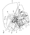
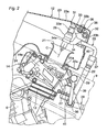
- Fig. 1 is a side view of a fuel supply device according to this embodiment and Fig. 2 is a view showing an essential part of the fuel supply device in an enlarged manner, wherein Fig. 2 depicts an air cleaner box and an upstream end portion of a throttle valve device in a broken state.
- Fig. 3 is a plan view of the fuel supply device.
- numeral 1 indicates a motorcycle engine according to this embodiment.
- This engine 1 is a water-cooled type parallel four-cylinder engine and is mounted on a motorcycle body frame 3 in a state that cylinders 2 are inclined in the frontward direction.
- the cylinder 2 is constituted of a cylinder body 5 which is projected obliquely upward to a front side of a body from a crank case 4, a cylinder head 6 mounted on an upper end portion of the cylinder body 5, a head cover 7 which is mounted on an upper end portion of the cylinder head 6 and the like.
- an exhaust pipe not shown in the drawing is connected to a body-front-side wall thereof and, at the same time, an intake device 8 described later is connected to a body-rear-side wall thereof.
- a pair of (left and right) tank rails 9 are extended rearwardly and downwardly from a head pipe not shown in the drawing and a fuel tank 10 (see Fig.1) is supported on the tank rails 9.
- a fuel tank 10 (see Fig.1) is supported on the tank rails 9.
- a recessed portion 11 which opens downwardly is formed at a lower portion of the body-front-side of thereof.
- This recessed portion 11 is formed such that a portion of a bottom wall of the fuel tank 10 can be projected upwardly so as to house an air cleaner box 12 of the intake device 8 therein.
- the fuel tank comprises a substantially vertically extending front wall, which is arranged on a backside of the air cleaner box in a front-to-aft direction of the motorcycle, and wherein a space is provided between said air cleaner box and vertically extending front wall of the fuel tank.
- the fuel tank comprises a front-side bottom wall, which is arranged above the air cleaner box, and which extends from the upper end of the vertically extending front wall of the fuel tank. Therein, the front wall and the front-side bottom wall of the fuel tank together form the recess 11, in which the air cleaner box is accommodated.
- the intake device 8 is constituted of a throttle valve device 14 for each cylinder which is connected to the cylinder head 6 by way of a rubber joint 13, the above-mentioned air cleaner box 12 which is mounted on an upstream-side end portion of the throttle valve device 14 and the like.
- the throttle valve device 14 is formed such that an intake passage formed in the inside of the throttle valve device 14 extends obliquely and lineally and upwardly toward the rear-side of the motorcycle-body.
- the throttle valve device 14 includes a slide type throttle valve 14a. Further, the throttle valve device 14 is arranged in a space defined between a pair of left and right tank rails 9, 9.
- an air funnel 21 which constitutes an opening end portion of the intake passage according to the present embodiment is mounted such that the air funnel 21 faces the inside of the air cleaner box 12 from below.
- the above-mentioned air cleaner box 12 is, as shown in Fig. 1 and Fig. 2, constituted of a box-like box body 22 which is mounted on the throttle valve device 14 and a lid body 23 which closes an opening of an upper end portion of the box body 22. Further, a planner shape of the air cleaner box 12 is, as shown in Fig. 3, formed in a semicircular shape bulged in the frontward direction. An intake box according to the present embodiment is constituted of this air cleaner box 12.
- a body-rear-side bottom thereof is mounted on the throttle valve device 14, and an intake duct 24 which extends obliquely and downwardly toward the front-side of the motorcycle body is integrally formed on the front-side end portion of the motorcycle-body (see Fig. 1). Further, to a connection portion with the intake duct 24 which is arranged at a front portion of the inside of the box body 22, an air cleaner element not shown in the drawing is mounted.
- this embodiment adopts a structure that a bottom wall 22a of the box body 22 is overlapped to an upper end portion of the throttle valve device 14 and the bottom wall 22a is pushed toward the box body 22 side by a flange 21a mounted on an air funnel 21 which is threaded into the throttle valve device 14.
- the lid body 23 is formed in a lid shape which opens downwardly and is replaceably mounted on the box body 22 by means of an engaging member such as a rubber band not shown in the drawing in a state that the lid body 23 covers an opening portion formed on an upper end of the box body 22.
- an engaging member such as a rubber band not shown in the drawing
- a secondary injector 26 which constitutes an injector of a fuel supply device 25 according to the present embodiment is mounted.
- the lid body 23 is, as shown in Fig. 2, formed such that an open peripheral portion of the lower end portion is formed to be fitted on the outside of an open peripheral portion of the box body 22.
- a fitting portion between the lid body 23 and the box body 22 is formed such that with respect to both of the lateral direction (the direction which is substantially orthogonal to the direction that the opening portion is directed, that is, the front-and-rear direction and the left-and-right direction) and the vertical direction (the direction in which the opening portion is directed), the movement of one of them restricts the movement of another. Since the box body 22 and the lid body 23 according to this embodiment are molded using fiber reinforced plastic, the smooth fitting portion can be formed.
- the fitting portion adopts a structure in which, for example, the whole area of the opening periphery of the box body 22 is formed such that the opening width is wider than a width of other portions having a stepped portion and open peripheral portion of the lid body 23 has the whole area thereof inserted into the inside of this enlarged-diameter portion.
- a sealing member such as an O ring is inserted in the fitting portion.
- the fuel supply device 25 is constituted of a primary injector 27 which is mounted on the throttle valve device 14 for each cylinder, the secondary injector 26 which is mounted on the lid body 23 for each cylinder, a fuel pipe assemblage 28 which is served for supplying fuel from a fuel tank 10 to these injectors 26, 27 and the like.
- the fuel supply device 25 according to this embodiment is configured such that fuel is supplied by the primary injector 27 over the whole region of the rotary region of the engine 1, and the fuel is supplied also from the secondary injector 26 when the rotary region of the engine 1 is at a high load such as the high rotary region or the rapid acceleration.
- the primary injector 27 has one end portion thereof mounted on the motorcycle-body rear-side wall of the throttle valve device 14 and another end portion connected with a fuel rail 29 and the fuel is injected to the downstream side of the throttle valve 14a.
- the fuel is supplied under pressure to the fuel rail 29 from the fuel pipe assemblage 28 explained later.
- the secondary injector 26 is mounted on an upper wall 23a of the lid body 23 by way of a bracket 31 and has an axis thereof aligned with an axis of the air funnel 21 (the center line of the intake passage) above the air funnel 21.
- the axis of the secondary injector 26 is indicated by a chain line C in Fig. 2.
- the secondary injector 26 according to this embodiment has a lower end portion thereof which injects the fuel arranged at a position which faces the inside of the air funnel 21 from above.
- the bracket 31 which mounts the secondary injector 26 to the lid body 23 includes, as shown in Fig. 2 and Fig. 3, a fuel rail 32 which extends in the motorcycle width direction along a rear wall 23b of the lid body 23, an upper arm 33 which extends toward the front side of the motorcycle body along the upper wall 23a of the lid body 23 from the fuel rail 32, a lower arm 34 which extends downwardly and obliquely toward the front side of the motorcycle body from the fuel rail 32, and a mounting seat 35 which is projected to the front side of the motorcycle body from the fuel rail 32 laterally along the upper arm 33.
- a fuel passage (not shown in the drawing) is formed in the inside thereof and the fuel pipe assemblage 28 described later is connected to the fuel passage.
- the upper arm 33 and the lower arm 34 of the bracket 31 are provided for each secondary injector 26.
- a socket 33a which mounts the upper end portion of the secondary injector 26 therein is formed on a motorcycle-front-side end portion thereof and, at the same time, in the inside of a fuel inlet (not shown in the drawing) of the secondary injector 26 which is mounted in the socket 33a, a fuel passage 33b for leading out the fuel from the inside of the fuel rail 32 is formed.
- a ring shaped folder 34a which fits a lower portion of the secondary injector 26 therein is provided to the motorcycle-front-side end portion thereof.
- the lower arm 34 is integrally formed with the fuel rail 32, while on the lower arm 34, the upper arm 33 which is formed separately from the lower arm 34 is mounted using fixing bolts 33c (see Fig. 3) in a state that the upper arm 33 holds the secondary injector 26 in a cooperative manner with the lower arm 34.
- a flat surface 35b which faces and is brought into contact with a lower surface of the upper wall 23a of the lid body 23 is formed around a screw hole 35a (see Fig. 3) into which a fixing bolt 36 is threaded.
- the fixing bolt 36 penetrates the upper wall 23a of the lid body 23 from above and is threaded into the screw hole 35a.
- downstream end portions thereof are respectively connected to the fuel rail 29 at the primary injector 27 side and the fuel rail 32 at the secondary injector 26 side by way of couplers 37, 38, while upstream end portions thereof are connected to a fuel discharge opening of a fuel pump (not shown in the drawing) in the inside of the fuel tank 10.
- the fuel supply device 25 adopts the constitution in which the excessive fuel is returned to the fuel tank 10 from a fuel return port 41a (see Fig. 3) of a pressure regulator 41 connected to the fuel rail 29 at the primary injector 27 side by way of a pipe not shown in the drawing.
- the pressure regulator 41 is, as has been well known conventionally, served for holding pressure in a fuel system to a given pressure.
- couplers 37, 38 couplers having the structure which enables couplers 37,38 to be mounted or dismounted without a tool and close the fuel passage in a state that they are removed from the fuel pipe assemblage 28 are used.
- the coupler 37 which is connected to the fuel rail 32 at the secondary injector 26 side is, as shown in Fig. 2, connected to the fuel pipe 39 which extends in the vertical direction from above behind the air cleaner box 12.
- the coupler 37 and the fuel rail 32 at the secondary injector 26 side are connected by a pipe 40 which penetrates the rear wall 23b of the lid body 23.
- the air funnel 21 which constitutes an opening end portion of the intake passage faces the inside of the air cleaner box 12 and the secondary injector 26 is mounted on the air cleaner box 12. Accordingly, in mounting the secondary injector 26, so-called, in the air in the vicinity of the opening end portion of the intake passage, a member which extends to the upstream side of the intake from the opening end portion of the intake passage and supports the secondary injector 26 is no more necessary.
- the bracket 31 which mounts the secondary injector 26 to the air cleaner box 12 can be formed to position between the secondary injector 26 and the air cleaner box 12 and hence, the bracket 31 can be formed in compact compared to a mounting part used conventionally.
- this holding of injector can be performed using the light-weighted and small-sized bracket 31 compared to the conventional holding of injector.
- the secondary injector 26 is integrally mounted on the lid body 23 of the air cleaner box 12 and can be removed from the engine 1 side together with the lid body 23. Accordingly, compared to the conventional technique, an operation to remove the secondary injector mounting member from the throttle valve device 14 is no more necessary. In this manner, in removing the secondary injector 26 together with the lid body 23, by removing the coupler 37 of the fuel pipe assemblage 28 upwardly, the removal of the secondary injector 26 can be performed in a state that most of the fuel supply system is mounted on the motorcycle body side.
- the fuel supply device 25 receives no restriction by such a mounting part in forming the air cleaner box 12 into the necessary minimum size.
- the air cleaner box 12 when the air cleaner box 12 is inserted into the inside of the recessed portion 11 of the fuel tank 10, by forming the air cleaner box 12 in compact as described above, it is possible to increase the capacity of the fuel tank 10 compared to the conventional technique.
- the fuel supply device 25 can widely open the periphery of the air funnel 21 and hence, there is no obstacle which interrupts the intake air flowing into the air funnel 21 so that the intake resistance is reduced compared to the conventional technique.
- bracket 31 which mounts the secondary injector 26 to the air cleaner box 12 has a function of supplying fuel to the secondary injector 26 and a function of supporting the secondary injector 26. Accordingly, in arranging the secondary injector 26 in the vicinity of the air funnel 21, members which are exclusively served for supporting the secondary injector 26 are no more necessary.
- parts which are served for mounting the secondary injector 26 to the air cleaner box 12 can be reduced as much as possible and hence, it is possible to mount the secondary injector 26 to the air cleaner box 12 in a more compact manner.
- the above-mentioned embodiment describes the fuel supply device 25 in which the primary injector 27 is mounted on the throttle valve device 14 and, at the same time, the secondary injector 26 is arranged in the inside of the air cleaner box 12.
- the teaching of the present invention is also applicable to the fuel supply device which supplies fuel using the secondary injector 26 over the whole region of the engine rotary region.
- a fuel supply device of a motorcycle engine in which an injector is arranged in an opening end portion of an intake passage such that an axis of the injector is made substantially parallel to a center line of the intake passage, the opening end portion of the intake passage is made to face the inside of an intake box, and the injector is mounted on the intake box.
- a member which extends to the upstream side of the intake from the opening end portion side of the intake passage for supporting the injector is no more necessary. Further, since parts which are served for mounting the injector to an intake box can be positioned between the injector and the intake box positioned in the vicinity of the injector, the parts become small-sized compared to mounting parts which have been used conventionally.
- the injector in holding the injector in the vicinity of the opening end portion of the intake passage, the increase of weight can be restricted as much as possible and, at the same time, the manufacturing cost can be reduced. Further, the injector is integrally mounted on the intake box and can be removed from the engine side together with the intake box and hence, the man-hours for maintenance can be reduced.
- the description above further discloses (amongst others) a fuel supply device of a motorcycle engine, wherein the injector is mounted on a wall which faces the opening end portion of the intake passage in the intake box in an opposed manner and is replaceable with respect to a wall which the intake passage penetrates.
- the description above also discloses (amongst others) a fuel supply device of a motorcycle engine, wherein the injector is mounted on the intake box by way of a bracket and the bracket is configured to form a fuel passage which supplies fuel to the injector in the inside thereof.
- the bracket which is served for mounting the injector to the intake box has the function of supplying the fuel to the injector and the function of supporting the injector and hence, in mounting the injector in the vicinity of the opening end portion of the intake passage, the member which is exclusively served for supporting the injector becomes unnecessary.
- the number of parts served for mounting the injector to the intake box can be reduced as much as possible and hence, it is possible to mount the injector to the intake box in a more compact form.
- an opening end portion of an intake passage is made to face the inside of an intake box and an injector is mounted on the intake box.
- a member which extends to an upstream side of intake from the opening end portion side of the intake passage for supporting the injector is no more necessary. Further, since it is sufficient to form the parts which mounts the injector to the intake box such that the parts are positioned between the injector and the intake box positioned in the vicinity of the injector, the parts become small-sized compared to conventionally used mounting parts.
- Said embodiment may be further improved in that the injector is mounted on a wall which faces an opening end portion of an intake passage in an intake box in an opposed manner and is replaceable with respect to a wall which the intake passage penetrates.
- Said embodiments may be still further improved in that the injector is mounted on the intake box by way of a bracket and the bracket is configured to form a fuel passage which supplies fuel to the injector in the inside thereof.
- the bracket which mounts the injector to the intake box has a function of supplying fuel to the injector as well as a function of supporting the injector, whereby in mounting the injector in the vicinity of the opening end portion of the intake passage, members which are exclusively used for supporting the injector become no more necessary.
- the opening end portion (an air funnel 21) of the intake passage is made to face the inside of an air cleaner box 12 and a secondary injector 26 is mounted on the air cleaner box 12.
- the present description further discloses a fuel supply device for a motorcycle engine having an injector arranged in and mounted to a vicinity of an opening end portion of an intake passage of each cylinder of the engine.
- an axis of the injector arranged in the opening end portion of the intake passage is located substantially parallel to a center line of the intake passage.
- the opening end portion of the intake passage is made to face the inside of an intake box or an intake silencer.
- the injector may be mounted to the intake box or to the intake silencer.
- the injector may be mounted to a wall which faces the opening end portion of the intake passage in the intake box or the intake silencer in an opposed manner.
- the injector is replaceable with respect to a wall which the intake passage penetrates.
- an air funnel which constitutes the opening end portion of the intake passage faces the inside of the intake silencer or an air cleaner box constituting the intake box, and a secondary injector which constitutes the injector is mounted on the air cleaner box or the intake silencer.
- the injector is mounted to the intake box or to the intake silencer by way of a bracket, said bracket having a fuel passage in the inside adapted to supply fuel to the injector.
- a further injector is provided which is mounted on a throttle valve device of the engine.
- the present invention further discloses a motorcycle engine having a fuel supply device as specified above.
- said engine may be a high-output engine, such as an engine mounted on a motorcycle for racing, in particular a water-cooled type parallel four-cylinder engine.
Applications Claiming Priority (2)
| Application Number | Priority Date | Filing Date | Title |
|---|---|---|---|
| JP2002220855A JP4077266B2 (ja) | 2002-07-30 | 2002-07-30 | 自動二輪車用エンジンの燃料供給装置 |
| EP03017284A EP1387081B1 (de) | 2002-07-30 | 2003-07-30 | Brennstoffversorgungseinrichtung und Motorradmotor damit |
Related Parent Applications (2)
| Application Number | Title | Priority Date | Filing Date |
|---|---|---|---|
| EP03017284A Division EP1387081B1 (de) | 2002-07-30 | 2003-07-30 | Brennstoffversorgungseinrichtung und Motorradmotor damit |
| EP03017284.5 Division | 2003-07-30 |
Publications (3)
| Publication Number | Publication Date |
|---|---|
| EP1852599A2 true EP1852599A2 (de) | 2007-11-07 |
| EP1852599A3 EP1852599A3 (de) | 2007-11-14 |
| EP1852599B1 EP1852599B1 (de) | 2010-11-03 |
Family
ID=30112916
Family Applications (6)
| Application Number | Title | Priority Date | Filing Date |
|---|---|---|---|
| EP05004130A Expired - Lifetime EP1533518B1 (de) | 2002-07-30 | 2003-07-30 | Motorrad |
| EP06019489A Expired - Lifetime EP1726821B1 (de) | 2002-07-30 | 2003-07-30 | Kraftstoffversorgungseinrichtung |
| EP07016496A Expired - Lifetime EP1852599B1 (de) | 2002-07-30 | 2003-07-30 | Brennstoffversorgungseinrichtung und Motorradmotor damit |
| EP07016495A Expired - Lifetime EP1852598B1 (de) | 2002-07-30 | 2003-07-30 | Brennstoffversorgungseinrichtung und Motorradmotor damit |
| EP03017284A Expired - Lifetime EP1387081B1 (de) | 2002-07-30 | 2003-07-30 | Brennstoffversorgungseinrichtung und Motorradmotor damit |
| EP07016497A Expired - Lifetime EP1852600B1 (de) | 2002-07-30 | 2003-07-30 | Brennstoffversorgungseinrichtung und Motorradmotor damit |
Family Applications Before (2)
| Application Number | Title | Priority Date | Filing Date |
|---|---|---|---|
| EP05004130A Expired - Lifetime EP1533518B1 (de) | 2002-07-30 | 2003-07-30 | Motorrad |
| EP06019489A Expired - Lifetime EP1726821B1 (de) | 2002-07-30 | 2003-07-30 | Kraftstoffversorgungseinrichtung |
Family Applications After (3)
| Application Number | Title | Priority Date | Filing Date |
|---|---|---|---|
| EP07016495A Expired - Lifetime EP1852598B1 (de) | 2002-07-30 | 2003-07-30 | Brennstoffversorgungseinrichtung und Motorradmotor damit |
| EP03017284A Expired - Lifetime EP1387081B1 (de) | 2002-07-30 | 2003-07-30 | Brennstoffversorgungseinrichtung und Motorradmotor damit |
| EP07016497A Expired - Lifetime EP1852600B1 (de) | 2002-07-30 | 2003-07-30 | Brennstoffversorgungseinrichtung und Motorradmotor damit |
Country Status (6)
| Country | Link |
|---|---|
| US (1) | US6843219B2 (de) |
| EP (6) | EP1533518B1 (de) |
| JP (1) | JP4077266B2 (de) |
| AT (6) | ATE487046T1 (de) |
| DE (6) | DE60318527T2 (de) |
| ES (3) | ES2308321T3 (de) |
Families Citing this family (31)
| Publication number | Priority date | Publication date | Assignee | Title |
|---|---|---|---|---|
| JP3970725B2 (ja) | 2002-09-11 | 2007-09-05 | 本田技研工業株式会社 | エンジン用燃料噴射装置 |
| JP4110024B2 (ja) * | 2003-03-31 | 2008-07-02 | 本田技研工業株式会社 | 小型車両におけるエンジンの燃料噴射装置 |
| US7104236B2 (en) * | 2003-09-30 | 2006-09-12 | Honda Motor Co., Ltd. | Intake air management apparatus for a vehicle, and motorcycle including same |
| JP4414250B2 (ja) * | 2004-03-01 | 2010-02-10 | 本田技研工業株式会社 | V型エンジンの吸気装置 |
| JP4238166B2 (ja) * | 2004-03-22 | 2009-03-11 | ヤマハ発動機株式会社 | 燃料供給装置および車両 |
| JP4293955B2 (ja) * | 2004-08-23 | 2009-07-08 | ヤマハ発動機株式会社 | 車両 |
| JP4464243B2 (ja) | 2004-08-25 | 2010-05-19 | 川崎重工業株式会社 | エンジンの吸気装置 |
| JP4281921B2 (ja) * | 2004-11-04 | 2009-06-17 | ヤマハ発動機株式会社 | 燃料供給装置及びそれを備えた車両 |
| CN101115921B (zh) | 2005-03-18 | 2011-08-31 | 丰田自动车株式会社 | 两系统燃料喷射式内燃机 |
| JP4602402B2 (ja) * | 2005-03-18 | 2010-12-22 | トヨタ自動車株式会社 | 内燃機関 |
| ES2724733T3 (es) | 2005-03-18 | 2019-09-13 | Toyota Motor Co Ltd | Motor de inyección de combustible de sistema doble |
| JP4369514B2 (ja) * | 2005-03-18 | 2009-11-25 | トヨタ自動車株式会社 | 2系統燃料噴射式内燃機関 |
| JP4616165B2 (ja) * | 2005-12-26 | 2011-01-19 | 株式会社ケーヒン | 2燃料噴射弁型のスロットルボデーにおける燃料供給管構造 |
| JP2007177688A (ja) * | 2005-12-28 | 2007-07-12 | Honda Motor Co Ltd | エンジンの燃料噴射装置 |
| JP4888114B2 (ja) * | 2006-12-28 | 2012-02-29 | スズキ株式会社 | 自動二輪車の燃料供給装置 |
| ITMI20070231A1 (it) * | 2007-02-08 | 2008-08-09 | Mv Agusta Motor S P A | Sistema di aspirazione per motore per motocicletta |
| JP2009029179A (ja) | 2007-07-24 | 2009-02-12 | Yamaha Motor Co Ltd | 車両 |
| WO2010065952A1 (en) * | 2008-12-05 | 2010-06-10 | Moto Tassinari, Inc. | Tunable air intake system |
| US8826888B1 (en) * | 2009-04-06 | 2014-09-09 | Cleanflex Power Systems, LLC | Apparatus for reducing engine emissions utilizing multiple types of fuels |
| JP5520623B2 (ja) * | 2010-01-29 | 2014-06-11 | 本田技研工業株式会社 | 燃料供給装置 |
| JP5855857B2 (ja) * | 2011-06-27 | 2016-02-09 | 株式会社ミクニ | インジェクタの取付構造 |
| JP5905256B2 (ja) * | 2011-12-28 | 2016-04-20 | 川崎重工業株式会社 | 燃料供給構造 |
| JP6089405B2 (ja) | 2012-01-23 | 2017-03-08 | スズキ株式会社 | 内燃機関の燃料供給装置 |
| JP6099193B2 (ja) * | 2013-01-30 | 2017-03-22 | 本田技研工業株式会社 | 自動二輪車 |
| EP2998568A4 (de) * | 2013-05-17 | 2016-12-28 | Kawasaki Heavy Ind Ltd | Lufteinlasskammer für ein sattelfahrzeug |
| JP5865323B2 (ja) * | 2013-09-30 | 2016-02-17 | 本田技研工業株式会社 | 鞍乗り型車両 |
| JP6011983B2 (ja) * | 2014-01-08 | 2016-10-25 | 本田技研工業株式会社 | 車両用エンジンにおける燃料供給構造 |
| JP6269081B2 (ja) * | 2014-01-15 | 2018-01-31 | スズキ株式会社 | インジェクタ取付構造 |
| US9548004B1 (en) * | 2015-04-16 | 2017-01-17 | Fireblast Global, Inc. | Pilot and burner system for firefighting training |
| JP6255611B2 (ja) * | 2015-05-29 | 2018-01-10 | 本田技研工業株式会社 | 配管接続構造 |
| JP6616728B2 (ja) * | 2016-04-06 | 2019-12-04 | 川崎重工業株式会社 | 乗物 |
Family Cites Families (20)
| Publication number | Priority date | Publication date | Assignee | Title |
|---|---|---|---|---|
| JPS5512262A (en) * | 1978-07-14 | 1980-01-28 | Yamaha Motor Co Ltd | Fuel injection type multi-cylinder internal-combustion engine |
| DE3370056D1 (en) * | 1982-06-09 | 1987-04-09 | Hitachi Ltd | Fuel injector body assembly |
| US4527516A (en) * | 1984-02-06 | 1985-07-09 | Pro-Staff Overload Enterprises Limited | Dual fuel engine |
| JP2522205B2 (ja) * | 1986-10-13 | 1996-08-07 | 日本電装株式会社 | エアクリ−ナ組立体支持構造 |
| JP2995198B2 (ja) | 1990-08-08 | 1999-12-27 | ヤマハ発動機株式会社 | 燃料噴射式自動二輪車 |
| JP3075806B2 (ja) * | 1991-10-07 | 2000-08-14 | ヤマハ発動機株式会社 | 車両用燃料ポンプの配設構造 |
| US5269275A (en) | 1992-11-02 | 1993-12-14 | David Rook | Pulse width modulated controller for nitrous oxide and fuel delivery |
| JP3690824B2 (ja) * | 1994-06-03 | 2005-08-31 | スズキ株式会社 | 内燃機関の燃料噴射装置 |
| JP3720402B2 (ja) * | 1995-02-17 | 2005-11-30 | ヤマハマリン株式会社 | 燃料噴射式船外機 |
| JPH10122100A (ja) | 1996-10-18 | 1998-05-12 | Keihin Corp | 自動二輪車における燃料噴射装置 |
| US6019074A (en) | 1998-03-11 | 2000-02-01 | Yamaha Hatsudoki Kabushiki Kaisha | Porting arrangement for two cycle engine |
| JP2000097131A (ja) * | 1998-09-22 | 2000-04-04 | Yamaha Motor Co Ltd | 燃料噴射弁の配置構造 |
| US6142123A (en) * | 1998-12-14 | 2000-11-07 | Cannondale Corporation | Motorcycle |
| JP4555413B2 (ja) | 1999-03-02 | 2010-09-29 | 本田技研工業株式会社 | バックボーン型自動二輪車における燃料噴射装置 |
| JP2000265922A (ja) | 1999-03-16 | 2000-09-26 | Honda Motor Co Ltd | 燃料噴射装置 |
| JP3925073B2 (ja) * | 2000-10-27 | 2007-06-06 | スズキ株式会社 | 燃料噴射式エンジンの吸気制御装置 |
| JP4202610B2 (ja) * | 2001-01-09 | 2008-12-24 | 本田技研工業株式会社 | 自動二輪車の電装品配置構造 |
| ATE266804T1 (de) * | 2001-09-14 | 2004-05-15 | Ducati Motor Holding Spa | Vorrichtung zum mischen von luft und brennstoff für eine brennkraftmaschine |
| ES2280466T3 (es) | 2001-09-20 | 2007-09-16 | Yamaha Hatsudoki Kabushiki Kaisha | Motocicleta con un motor de combustion interna. |
| JP4108954B2 (ja) | 2001-10-05 | 2008-06-25 | ヤマハ発動機株式会社 | 自動二輪車の燃料系配置構造 |
-
2002
- 2002-07-30 JP JP2002220855A patent/JP4077266B2/ja not_active Expired - Lifetime
-
2003
- 2003-07-30 DE DE60318527T patent/DE60318527T2/de not_active Expired - Lifetime
- 2003-07-30 AT AT07016497T patent/ATE487046T1/de not_active IP Right Cessation
- 2003-07-30 AT AT07016495T patent/ATE480707T1/de not_active IP Right Cessation
- 2003-07-30 AT AT06019489T patent/ATE487056T1/de not_active IP Right Cessation
- 2003-07-30 US US10/630,225 patent/US6843219B2/en not_active Expired - Lifetime
- 2003-07-30 DE DE60334862T patent/DE60334862D1/de not_active Expired - Lifetime
- 2003-07-30 EP EP05004130A patent/EP1533518B1/de not_active Expired - Lifetime
- 2003-07-30 AT AT03017284T patent/ATE383512T1/de not_active IP Right Cessation
- 2003-07-30 DE DE60321926T patent/DE60321926D1/de not_active Expired - Lifetime
- 2003-07-30 DE DE60334167T patent/DE60334167D1/de not_active Expired - Lifetime
- 2003-07-30 EP EP06019489A patent/EP1726821B1/de not_active Expired - Lifetime
- 2003-07-30 AT AT05004130T patent/ATE399938T1/de not_active IP Right Cessation
- 2003-07-30 EP EP07016496A patent/EP1852599B1/de not_active Expired - Lifetime
- 2003-07-30 EP EP07016495A patent/EP1852598B1/de not_active Expired - Lifetime
- 2003-07-30 DE DE60334860T patent/DE60334860D1/de not_active Expired - Lifetime
- 2003-07-30 EP EP03017284A patent/EP1387081B1/de not_active Expired - Lifetime
- 2003-07-30 AT AT07016496T patent/ATE487045T1/de not_active IP Right Cessation
- 2003-07-30 ES ES05004130T patent/ES2308321T3/es not_active Expired - Lifetime
- 2003-07-30 ES ES03017284T patent/ES2299648T3/es not_active Expired - Lifetime
- 2003-07-30 DE DE60334863T patent/DE60334863D1/de not_active Expired - Lifetime
- 2003-07-30 ES ES07016495T patent/ES2349801T3/es not_active Expired - Lifetime
- 2003-07-30 EP EP07016497A patent/EP1852600B1/de not_active Expired - Lifetime
Non-Patent Citations (1)
| Title |
|---|
| None |
Also Published As
Similar Documents
| Publication | Publication Date | Title |
|---|---|---|
| EP1852599B1 (de) | Brennstoffversorgungseinrichtung und Motorradmotor damit | |
| JP3970725B2 (ja) | エンジン用燃料噴射装置 | |
| JP5798491B2 (ja) | 過給機付き自動二輪車 | |
| KR100359702B1 (ko) | 백본형 자동이륜차의 연료분사 장치 | |
| JP4290948B2 (ja) | エンジン用燃料噴射装置 | |
| US7174981B2 (en) | Air intake device for scooter-type two-wheeled motor vehicle | |
| JP4344754B2 (ja) | エンジン用燃料噴射装置 | |
| EP3741987B1 (de) | Luftreiniger | |
| JP4107677B2 (ja) | 自動二輪車 | |
| JP4097684B2 (ja) | 自動二輪車 | |
| US8302727B2 (en) | Exhaust pipe for a vehicle | |
| JP4097685B2 (ja) | 自動二輪車 | |
| JP4390218B2 (ja) | 自動二輪車用のエンジン用燃料噴射装置 |
Legal Events
| Date | Code | Title | Description |
|---|---|---|---|
| PUAI | Public reference made under article 153(3) epc to a published international application that has entered the european phase |
Free format text: ORIGINAL CODE: 0009012 |
|
| PUAL | Search report despatched |
Free format text: ORIGINAL CODE: 0009013 |
|
| 17P | Request for examination filed |
Effective date: 20070822 |
|
| AC | Divisional application: reference to earlier application |
Ref document number: 1387081 Country of ref document: EP Kind code of ref document: P |
|
| AK | Designated contracting states |
Kind code of ref document: A2 Designated state(s): AT BE BG CH CY CZ DE DK EE ES FI FR GB GR HU IE IT LI LU MC NL PT RO SE SI SK TR |
|
| AK | Designated contracting states |
Kind code of ref document: A3 Designated state(s): AT BE BG CH CY CZ DE DK EE ES FI FR GB GR HU IE IT LI LU MC NL PT RO SE SI SK TR |
|
| 17Q | First examination report despatched |
Effective date: 20080310 |
|
| AKX | Designation fees paid |
Designated state(s): AT BE BG CH CY CZ DE DK EE ES FI FR GB GR HU IE IT LI LU MC NL PT RO SE SI SK TR |
|
| GRAP | Despatch of communication of intention to grant a patent |
Free format text: ORIGINAL CODE: EPIDOSNIGR1 |
|
| RIC1 | Information provided on ipc code assigned before grant |
Ipc: F02M 35/14 20060101AFI20100312BHEP Ipc: F02M 61/14 20060101ALI20100312BHEP Ipc: F02M 69/32 20060101ALI20100312BHEP Ipc: F02M 69/28 20060101ALI20100312BHEP Ipc: F02M 69/46 20060101ALI20100312BHEP Ipc: F02M 69/04 20060101ALI20100312BHEP |
|
| RTI1 | Title (correction) |
Free format text: MOTORCYCLE AND FUEL DELIVERY DEVICE THEREFORE |
|
| GRAS | Grant fee paid |
Free format text: ORIGINAL CODE: EPIDOSNIGR3 |
|
| GRAA | (expected) grant |
Free format text: ORIGINAL CODE: 0009210 |
|
| AC | Divisional application: reference to earlier application |
Ref document number: 1387081 Country of ref document: EP Kind code of ref document: P |
|
| AK | Designated contracting states |
Kind code of ref document: B1 Designated state(s): AT BE BG CH CY CZ DE DK EE ES FI FR GB GR HU IE IT LI LU MC NL PT RO SE SI SK TR |
|
| REG | Reference to a national code |
Ref country code: GB Ref legal event code: FG4D |
|
| REG | Reference to a national code |
Ref country code: CH Ref legal event code: EP |
|
| REG | Reference to a national code |
Ref country code: IE Ref legal event code: FG4D |
|
| REF | Corresponds to: |
Ref document number: 60334862 Country of ref document: DE Date of ref document: 20101216 Kind code of ref document: P |
|
| REG | Reference to a national code |
Ref country code: NL Ref legal event code: VDEP Effective date: 20101103 |
|
| PG25 | Lapsed in a contracting state [announced via postgrant information from national office to epo] |
Ref country code: SE Free format text: LAPSE BECAUSE OF FAILURE TO SUBMIT A TRANSLATION OF THE DESCRIPTION OR TO PAY THE FEE WITHIN THE PRESCRIBED TIME-LIMIT Effective date: 20101103 Ref country code: NL Free format text: LAPSE BECAUSE OF FAILURE TO SUBMIT A TRANSLATION OF THE DESCRIPTION OR TO PAY THE FEE WITHIN THE PRESCRIBED TIME-LIMIT Effective date: 20101103 Ref country code: FI Free format text: LAPSE BECAUSE OF FAILURE TO SUBMIT A TRANSLATION OF THE DESCRIPTION OR TO PAY THE FEE WITHIN THE PRESCRIBED TIME-LIMIT Effective date: 20101103 Ref country code: PT Free format text: LAPSE BECAUSE OF FAILURE TO SUBMIT A TRANSLATION OF THE DESCRIPTION OR TO PAY THE FEE WITHIN THE PRESCRIBED TIME-LIMIT Effective date: 20110303 Ref country code: AT Free format text: LAPSE BECAUSE OF FAILURE TO SUBMIT A TRANSLATION OF THE DESCRIPTION OR TO PAY THE FEE WITHIN THE PRESCRIBED TIME-LIMIT Effective date: 20101103 Ref country code: SI Free format text: LAPSE BECAUSE OF FAILURE TO SUBMIT A TRANSLATION OF THE DESCRIPTION OR TO PAY THE FEE WITHIN THE PRESCRIBED TIME-LIMIT Effective date: 20101103 Ref country code: BG Free format text: LAPSE BECAUSE OF FAILURE TO SUBMIT A TRANSLATION OF THE DESCRIPTION OR TO PAY THE FEE WITHIN THE PRESCRIBED TIME-LIMIT Effective date: 20110203 |
|
| PG25 | Lapsed in a contracting state [announced via postgrant information from national office to epo] |
Ref country code: GR Free format text: LAPSE BECAUSE OF FAILURE TO SUBMIT A TRANSLATION OF THE DESCRIPTION OR TO PAY THE FEE WITHIN THE PRESCRIBED TIME-LIMIT Effective date: 20110204 |
|
| PG25 | Lapsed in a contracting state [announced via postgrant information from national office to epo] |
Ref country code: CZ Free format text: LAPSE BECAUSE OF FAILURE TO SUBMIT A TRANSLATION OF THE DESCRIPTION OR TO PAY THE FEE WITHIN THE PRESCRIBED TIME-LIMIT Effective date: 20101103 Ref country code: EE Free format text: LAPSE BECAUSE OF FAILURE TO SUBMIT A TRANSLATION OF THE DESCRIPTION OR TO PAY THE FEE WITHIN THE PRESCRIBED TIME-LIMIT Effective date: 20101103 Ref country code: BE Free format text: LAPSE BECAUSE OF FAILURE TO SUBMIT A TRANSLATION OF THE DESCRIPTION OR TO PAY THE FEE WITHIN THE PRESCRIBED TIME-LIMIT Effective date: 20101103 Ref country code: ES Free format text: LAPSE BECAUSE OF FAILURE TO SUBMIT A TRANSLATION OF THE DESCRIPTION OR TO PAY THE FEE WITHIN THE PRESCRIBED TIME-LIMIT Effective date: 20110214 |
|
| PG25 | Lapsed in a contracting state [announced via postgrant information from national office to epo] |
Ref country code: SK Free format text: LAPSE BECAUSE OF FAILURE TO SUBMIT A TRANSLATION OF THE DESCRIPTION OR TO PAY THE FEE WITHIN THE PRESCRIBED TIME-LIMIT Effective date: 20101103 Ref country code: DK Free format text: LAPSE BECAUSE OF FAILURE TO SUBMIT A TRANSLATION OF THE DESCRIPTION OR TO PAY THE FEE WITHIN THE PRESCRIBED TIME-LIMIT Effective date: 20101103 Ref country code: RO Free format text: LAPSE BECAUSE OF FAILURE TO SUBMIT A TRANSLATION OF THE DESCRIPTION OR TO PAY THE FEE WITHIN THE PRESCRIBED TIME-LIMIT Effective date: 20101103 |
|
| PLBE | No opposition filed within time limit |
Free format text: ORIGINAL CODE: 0009261 |
|
| STAA | Information on the status of an ep patent application or granted ep patent |
Free format text: STATUS: NO OPPOSITION FILED WITHIN TIME LIMIT |
|
| 26N | No opposition filed |
Effective date: 20110804 |
|
| REG | Reference to a national code |
Ref country code: DE Ref legal event code: R097 Ref document number: 60334862 Country of ref document: DE Effective date: 20110804 |
|
| PG25 | Lapsed in a contracting state [announced via postgrant information from national office to epo] |
Ref country code: IT Free format text: LAPSE BECAUSE OF FAILURE TO SUBMIT A TRANSLATION OF THE DESCRIPTION OR TO PAY THE FEE WITHIN THE PRESCRIBED TIME-LIMIT Effective date: 20101103 |
|
| PG25 | Lapsed in a contracting state [announced via postgrant information from national office to epo] |
Ref country code: MC Free format text: LAPSE BECAUSE OF NON-PAYMENT OF DUE FEES Effective date: 20110731 |
|
| REG | Reference to a national code |
Ref country code: CH Ref legal event code: PL |
|
| REG | Reference to a national code |
Ref country code: IE Ref legal event code: MM4A |
|
| PG25 | Lapsed in a contracting state [announced via postgrant information from national office to epo] |
Ref country code: CH Free format text: LAPSE BECAUSE OF NON-PAYMENT OF DUE FEES Effective date: 20110731 Ref country code: LI Free format text: LAPSE BECAUSE OF NON-PAYMENT OF DUE FEES Effective date: 20110731 |
|
| PG25 | Lapsed in a contracting state [announced via postgrant information from national office to epo] |
Ref country code: IE Free format text: LAPSE BECAUSE OF NON-PAYMENT OF DUE FEES Effective date: 20110730 |
|
| PG25 | Lapsed in a contracting state [announced via postgrant information from national office to epo] |
Ref country code: CY Free format text: LAPSE BECAUSE OF EXPIRATION OF PROTECTION Effective date: 20101103 Ref country code: LU Free format text: LAPSE BECAUSE OF NON-PAYMENT OF DUE FEES Effective date: 20110730 |
|
| PG25 | Lapsed in a contracting state [announced via postgrant information from national office to epo] |
Ref country code: TR Free format text: LAPSE BECAUSE OF FAILURE TO SUBMIT A TRANSLATION OF THE DESCRIPTION OR TO PAY THE FEE WITHIN THE PRESCRIBED TIME-LIMIT Effective date: 20101103 |
|
| PG25 | Lapsed in a contracting state [announced via postgrant information from national office to epo] |
Ref country code: HU Free format text: LAPSE BECAUSE OF FAILURE TO SUBMIT A TRANSLATION OF THE DESCRIPTION OR TO PAY THE FEE WITHIN THE PRESCRIBED TIME-LIMIT Effective date: 20101103 |
|
| REG | Reference to a national code |
Ref country code: FR Ref legal event code: PLFP Year of fee payment: 14 |
|
| REG | Reference to a national code |
Ref country code: FR Ref legal event code: PLFP Year of fee payment: 15 |
|
| REG | Reference to a national code |
Ref country code: FR Ref legal event code: PLFP Year of fee payment: 16 |
|
| PGFP | Annual fee paid to national office [announced via postgrant information from national office to epo] |
Ref country code: GB Payment date: 20220720 Year of fee payment: 20 Ref country code: DE Payment date: 20220620 Year of fee payment: 20 |
|
| PGFP | Annual fee paid to national office [announced via postgrant information from national office to epo] |
Ref country code: FR Payment date: 20220720 Year of fee payment: 20 |
|
| P01 | Opt-out of the competence of the unified patent court (upc) registered |
Effective date: 20230526 |
|
| REG | Reference to a national code |
Ref country code: DE Ref legal event code: R071 Ref document number: 60334862 Country of ref document: DE |
|
| REG | Reference to a national code |
Ref country code: GB Ref legal event code: PE20 Expiry date: 20230729 |
|
| PG25 | Lapsed in a contracting state [announced via postgrant information from national office to epo] |
Ref country code: GB Free format text: LAPSE BECAUSE OF EXPIRATION OF PROTECTION Effective date: 20230729 |