EP1850368B2 - Filmbildende zusammensetzung und organisches elektrolumineszenzierendes bauelement - Google Patents
Filmbildende zusammensetzung und organisches elektrolumineszenzierendes bauelement Download PDFInfo
- Publication number
- EP1850368B2 EP1850368B2 EP06713261.3A EP06713261A EP1850368B2 EP 1850368 B2 EP1850368 B2 EP 1850368B2 EP 06713261 A EP06713261 A EP 06713261A EP 1850368 B2 EP1850368 B2 EP 1850368B2
- Authority
- EP
- European Patent Office
- Prior art keywords
- film
- forming composition
- solvent
- composition according
- hole
- Prior art date
- Legal status (The legal status is an assumption and is not a legal conclusion. Google has not performed a legal analysis and makes no representation as to the accuracy of the status listed.)
- Active
Links
Images


Classifications
-
- H—ELECTRICITY
- H05—ELECTRIC TECHNIQUES NOT OTHERWISE PROVIDED FOR
- H05B—ELECTRIC HEATING; ELECTRIC LIGHT SOURCES NOT OTHERWISE PROVIDED FOR; CIRCUIT ARRANGEMENTS FOR ELECTRIC LIGHT SOURCES, IN GENERAL
- H05B33/00—Electroluminescent light sources
- H05B33/12—Light sources with substantially two-dimensional radiating surfaces
- H05B33/20—Light sources with substantially two-dimensional radiating surfaces characterised by the chemical or physical composition or the arrangement of the material in which the electroluminescent material is embedded
-
- C—CHEMISTRY; METALLURGY
- C09—DYES; PAINTS; POLISHES; NATURAL RESINS; ADHESIVES; COMPOSITIONS NOT OTHERWISE PROVIDED FOR; APPLICATIONS OF MATERIALS NOT OTHERWISE PROVIDED FOR
- C09D—COATING COMPOSITIONS, e.g. PAINTS, VARNISHES OR LACQUERS; FILLING PASTES; CHEMICAL PAINT OR INK REMOVERS; INKS; CORRECTING FLUIDS; WOODSTAINS; PASTES OR SOLIDS FOR COLOURING OR PRINTING; USE OF MATERIALS THEREFOR
- C09D11/00—Inks
- C09D11/30—Inkjet printing inks
-
- C—CHEMISTRY; METALLURGY
- C09—DYES; PAINTS; POLISHES; NATURAL RESINS; ADHESIVES; COMPOSITIONS NOT OTHERWISE PROVIDED FOR; APPLICATIONS OF MATERIALS NOT OTHERWISE PROVIDED FOR
- C09D—COATING COMPOSITIONS, e.g. PAINTS, VARNISHES OR LACQUERS; FILLING PASTES; CHEMICAL PAINT OR INK REMOVERS; INKS; CORRECTING FLUIDS; WOODSTAINS; PASTES OR SOLIDS FOR COLOURING OR PRINTING; USE OF MATERIALS THEREFOR
- C09D11/00—Inks
- C09D11/50—Sympathetic, colour changing or similar inks
-
- H—ELECTRICITY
- H10—SEMICONDUCTOR DEVICES; ELECTRIC SOLID-STATE DEVICES NOT OTHERWISE PROVIDED FOR
- H10K—ORGANIC ELECTRIC SOLID-STATE DEVICES
- H10K71/00—Manufacture or treatment specially adapted for the organic devices covered by this subclass
- H10K71/10—Deposition of organic active material
- H10K71/12—Deposition of organic active material using liquid deposition, e.g. spin coating
- H10K71/15—Deposition of organic active material using liquid deposition, e.g. spin coating characterised by the solvent used
-
- H—ELECTRICITY
- H10—SEMICONDUCTOR DEVICES; ELECTRIC SOLID-STATE DEVICES NOT OTHERWISE PROVIDED FOR
- H10K—ORGANIC ELECTRIC SOLID-STATE DEVICES
- H10K50/00—Organic light-emitting devices
- H10K50/10—OLEDs or polymer light-emitting diodes [PLED]
- H10K50/14—Carrier transporting layers
-
- H—ELECTRICITY
- H10—SEMICONDUCTOR DEVICES; ELECTRIC SOLID-STATE DEVICES NOT OTHERWISE PROVIDED FOR
- H10K—ORGANIC ELECTRIC SOLID-STATE DEVICES
- H10K71/00—Manufacture or treatment specially adapted for the organic devices covered by this subclass
- H10K71/10—Deposition of organic active material
- H10K71/12—Deposition of organic active material using liquid deposition, e.g. spin coating
- H10K71/13—Deposition of organic active material using liquid deposition, e.g. spin coating using printing techniques, e.g. ink-jet printing or screen printing
- H10K71/135—Deposition of organic active material using liquid deposition, e.g. spin coating using printing techniques, e.g. ink-jet printing or screen printing using ink-jet printing
Definitions
- the present invention relates to a film-forming composition that is used for the formation of a hole-injecting/transporting layer of an organic electroluminescent device, and an organic electroluminescent device wherein the hole-injecting/transporting layer is formed of the film-forming composition.
- Patent Document 1 discloses a method used to form a hole-injecting/transporting layer by a spin-coating technique wherein a solution containing a hole-transporting material, polyether with aromatic diamine, and an electron-accepting compound, tris(4-bromophenyl)amminium hexachloroantimonate (TBPAH), in dichloromethane is used.
- Patent Document 2 discloses a method used to form a hole-injecting layer by a spin-coating technique, wherein a solution containing polyether with aromatic diamine in 1,2-dichloroethane is used.
- Patent Document 3 discloses a method used to form a hole-injecting layer by a spin-coating technique, wherein a solution containing a mixture of 4,4'-bis[N-(m-tolyl)-N-phenylamino]biphenyl and an electron-accepting compound, antimony pentachloride, in 1,2-dichloroethane is used.
- Patent Documents 4 and 5 compositions for forming a hole-injecting/transporting layer by an inkjet technique are described.
- Patent Document 4 discloses a coating liquid prepared by dispersing copper phthalocyanine or a conductive polymer, polyethylenedioxythiophene (PEDT), and polystyrene sulfonate (PSS) in a mixed solvent of water, lower alcohol and other components.
- Patent Document 5 a coating liquid prepared by dispersing PEDT and PSS in a solvent composed of water, ethanol and dipropylene glycol is disclosed.
- JP 2003 213002 A relates to an aromatic diamine-containing polymer having a specific repeating unit(s), which is used for preparing an organic electroluminescent (EL) element.
- EL organic electroluminescent
- Hole-injecting/transporting compounds are prepared which exhibit a high solubility in organic solvents such as N-methylpyrrolidone (NMP), tetrahydrofurane (THF), cyclohexanone, chloroform, methylene chloride, tetraline, toluene, methyl benzoate and ethyl acetate.
- NMP N-methylpyrrolidone
- THF tetrahydrofurane
- cyclohexanone chloroform
- methylene chloride tetraline
- toluene methyl benzoate
- ethyl acetate ethyl acetate.
- WO 2005/089024 A1 describes a composition for forming a charge-transport film which comprises a charge-transporting compound and a specific ionic compound. The composition is dissolved in a solvent for forming a film by a wet coating method.
- US 2002/0197392 A1 discloses a composition including a solvent and a functional material, and a method for producing a functional element such as an organic EL element by applying the composition as a pattern to form a thin film.
- a functional element such as an organic EL element
- Patent Document 1 Japanese Unexamined Patent Application Publication No. H11-283750
- Patent Document 2 Japanese Unexamined Patent Application Publication No. 2000-36390
- Patent Document 3 Japanese Unexamined Patent Application Publication No. 2002-56985
- Patent Document 4 Japanese Unexamined Patent Application Publication No. 2000-106278
- Patent Document 5 Japanese Unexamined Patent Application Publication No. 2004-204114
- compositions for the formation of a hole-injecting/transporting layer that are used in known wet film-forming methods often contain water as solvent. In general, the presence of water would impair the properties of an organic electroluminescent device. Therefore, as much water as possible must be removed from the formed layer when such a water-containing composition is used. It is difficult to eliminate water from the formed hole-injecting/transporting layer.
- Existing organic electroluminescent devices have deteriorated properties due to the moisture remaining inside the layer. In manufacturing of the organic electroluminescent devices, fluctuations in the remaining moisture amounts among individual organic electroluminescent devices that occur during the film-forming step results in the devices having inconsistent properties.
- film-forming materials used for producing a hole-injecting layer or a hole-transporting layer of an organic electroluminescent device such as 4,4'-bis[N-(m-tolyl)-N-phenylamino]biphenyl and polyether with aromatic diamine, have low solubility in commonly used solvents, thus making it difficult to prepare a solution of an appropriate concentration when producing a thin layer of organic material by a wet film-forming method.
- a solvent used to prepare a solution used in a wet film-forming method is required to have not only a capability of dissolution of a hole-injecting/transporting material but also a high affinity for the substrate.
- a drying rate of the coating liquid is significantly important for controlling the efficiency of manufacturing processes.
- the use of a solvent with a higher vapor pressure causes the solvent to evaporate during spraying of the coating liquid from a spray nozzle onto a surface to be coated and clogging in the nozzle to occur, thus making it difficult to form a highly uniform organic layer.
- An object of the present invention is to provide a water-free film-forming composition, which is used to form a hole-injecting layer or a hole-transporting layer of an organic electroluminescent device.
- the present invention also aims at providing a film-forming composition that attains one, preferably all, of the improvements in the solubility of a hole-injecting/transporting material, stability during discharge from a spray nozzle, affinity between a formed coating film and a substrate layer, and appropriateness of drying rate for the formation of a uniform coating layer.
- the film-forming composition of present invention is used in an organic electroluminescent device wherein the hole-injecting/transporting layer is formed by using such a film-forming composition.
- the film-forming composition according to the present invention is a composition used to form a hole-injecting/transporting layer of an organic electroluminescent device, wherein the film-forming composition contains a hole-injecting/transporting material, an electron-accepting compound and a liquid in which the material and the compound are dissolved; the liquid contains a first solvent whose molecule has an aromatic ring and/or an aliphatic ring and an oxygen atom and which has either a boiling point of at least 200°C or a vapor pressure of 133.3 Pa (1 torr) or lower at 25°C and the amount of the first solvent contained in the composition is 3 wt% or more, and wherein the liquid further comprises a second solvent, which has an aromatic ring and/or an aliphatic ring and an oxygen atom in its molecule and has a boiling point of lower than 200°C and a vapor pressure of higher than 133.3 Pa (1 torr) at 25°C, and the weight ratio between the second and first solvents W 2 /W 1 ,
- the organic electroluminescent device is characterized in that its hole-injecting/transporting layers are formed by using such a film-forming composition.
- a film-forming composition that attains an improvement in the solubility of a hole-injecting/transporting material and/or an electron-accepting compound, has a drying rate appropriate for stable formation of a uniform coating film, and is suitable for the formation of a hole-injecting/transporting layer is obtained.
- a solvent containing a compound whose molecule has an aromatic ring and/or an aliphatic ring and an oxygen atom shows high solubility of a hole-injecting/transporting material such as aromatic amine and an electron-accepting compound such as aromatic boron compounds, so that the concentration of the hole-injecting/transporting material and the electron-accepting compound in the composition is increased. Therefore, such a solvent enables to prepare a composition with an optimal concentration or viscosity.
- the first solvent has a boiling point of at least 200°C or a vapor pressure 1 torr (133 Pa) or lower at 25°C, thus being extremely hard to evaporate.
- the use of the first solvent in applications using an inkjet method or a spraying method can prevent clogging in the spray head nozzle caused by the solvent evaporation. Also, evaporation of the first solvent from the coating film is reduced, so that the self-leveling property of the coating film leads to the formation of a film without any unevenness in thickness.
- the film-forming composition according to the present invention is suitable for the formation of a hole-injecting/transporting layer using an inkjet method or a spraying method due to its resistance to dryness and excellent leveling property.
- the device obtained thereby acquires consistent properties and an improved hole-transporting performance.
- the liquid comprises the first solvent and the second solvent, which has an aromatic ring and/or an aliphatic ring and an oxygen atom in its molecule and has a boiling point of lower than 200°C and a vapor pressure of higher than 133.3 Pa (1 torr) at 25°C, and the weight ratio between the second and first solvents W 2 /W 1 , where W 2 is the weight proportion of the second solvent and W 1 the weight proportion of the first solvent, is 1 to 20.
- W 2 /W 1 of 1 to 2.5 is especially preferable.
- the liquid comprises aromatic ester (weight proportion W a ) as the first solvent and a low-evaporability solvent (weight proportion W b ) that is classified into the same type as the first solvent and has a higher boiling point or a lower vapor pressure at 25°C when compared with the aromatic ester, and the weight ratio W a /W b is 1 to 20.
- W a /W b of 1 to 2.5 is especially preferable. In this case, it is advisable to use benzoate as the aromatic ester and acetate having an aromatic ring as the low-evaporability solvent.
- the hole-injecting/transporting material may be aromatic amine
- the electron-accepting compound may be an aromatic boron compound and/or its salt.
- An organic electroluminescent device is formed by laminating many layers of organic compounds, and thus each of the layers should be uniform.
- moisture entrained in film-forming compositions may lead to decreased evenness of the film due to the presence of moisture in the coating film. Therefore, it is advisable to reduce the moisture content in the film-forming composition of the present invention as much as possible.
- the moisture content of the film-forming composition of the present invention is preferably not more than 1 wt% because an organic electroluminescent device incorporates a lot of materials that are significantly damaged by water (e.g., aluminum constituting a cathode). This improves uniformity of the film and prevents the organic electroluminescent device, particularly the cathode, from deteriorating.
- the film-forming composition of the present invention is suitable for use as a coating liquid to produce at least one of a hole-injecting layer and a hole-transporting layer.
- a film formed of the film-forming composition according to the present invention has excellent uniformity.
- This film may be a hole-injecting/transporting layer formed onto a certain area of the substrate surface where unevenness due to the presence of patterned electrodes or walls between imaging elements has been left.
- the film-forming composition of the present invention is suitable for use as a coating liquid to produce a hole-injecting layer and/or a hole-transporting layer between an anode and a luminescent layer.
- the layer is referred to as "hole-injecting layer,” and if there are two or more layers, the layer next to the anode is referred to as “hole-injecting layer” and other layers are collectively referred to as “hole-transporting layer.”
- holes-injecting layer layers between the anode and the luminescent layer are collectively called “hole-injecting/transporting layer.”
- the film-forming composition of the present invention contains a hole-injecting/transporting material and an electron-accepting compound that forms at least one of a hole-injecting layer and a hole-transporting layer of an organic electroluminescent device, in addition to a liquid in which the hole-injecting/transporting material and the electron-accepting compound are dissolved.
- the liquid has an aromatic ring and/or an aliphatic ring and an oxygen atom in its molecules and contains a first solvent, which has a boiling point of at least 200°C or a vapor pressure of 133.3 Pa (1 torr) or lower at 25°C.
- the aromatic ring may be any of an aromatic hydrocarbon ring and an aromatic heterocyclic ring but preferably is an aromatic hydrocarbon ring.
- the concentration of the first solvent contained in the film-forming composition is typically at least 3 wt%, preferably at least 10 wt%, more preferably at least 50 wt%, and most preferably at least 80 wt%. It is advisable that 50 wt% or more of the liquid contained in the composition is a first solvent.
- Requirements for the first solvent are only a boiling point of at least 200°C and a vapor pressure of 133.3 Pa (1 torr) or lower at 25°C, and there is no specific requirement of the upper limit of the boiling point or the lower limit of the vapor pressure. Ranges of preferred boiling points and vapor pressures may vary depending on the ratio of the first solvent to the entire solvent, the nature of other solvents simultaneously used or other factors, and thus there is no standard of them. However, in general, a suitable boiling point of the first solvent is approximately 200 to 300°C and a suitable vapor pressure at 25°C is approximately 0.133 to 133 Pa (0.001 to 1 torr).
- the first solvent examples include methyl benzoate, ethyl benzoate, isopropyl benzoate, propyl benzoate, n-butyl benzoate, dimethyl phthalate, 2-phenoxyethyl acetate, phenyl propionate and other aromatic esters.
- the liquid may contain two or more kinds of first solvent.
- the liquid may contain a first solvent with lower evaporability and another first solvent with higher evaporability.
- the liquid may contain at least one kind of first solvents and at least one kind of second solvents, which have an aromatic ring and/or an aliphatic ring and an oxygen atom in their molecule as described in claim 1.
- Examples of the second solvent include:
- a second solvent has a boiling point of lower than 200°C and a vapor pressure of higher than 133.3 Pa (1 torr) at 25°C.
- the second solvent preferably has a boiling point of 150°C or higher and a vapor pressure of 666.5 Pa (5 torr) or lower at 25°C. It is preferable that the hole-injecting/transporting material and/or the electron-accepting compound are dissolved well in the second solvent, and the solubility may be larger than that of first solvent.
- the liquid may contain at least one kind of first solvents and at least one kind of second solvents.
- the ratio W 2 /W 1 where W 2 is the weight proportion of the second solvent relative to the entire liquid and W 1 the weight proportion of the first solvent, is 1 to 20 and preferably 1 to 19. If the amount of the first solvent is so low as to deviate from these ranges, the present invention may provide insufficient effects, while if the amount is too high, the use of the second solvent other than the first solvent may not have the sufficient effect of adjusting the drying rate.
- the ratio W 2 /W 1 may be 3 to 19. To achieve better evenness of the film, W 2 /W 1 is preferably 1 to 2.5.
- the liquid may contain two or more kinds of first solvents.
- a first solvent with higher evaporability and another first solvent with lower evaporability may be contained therein.
- a high-evaporability first solvent having a boiling point of 200 to 240°C or a vapor pressure of 133.3 to 13.3 Pa (1 to 0.1 torr) at 25°C may be mixed with a low-evaporability first solvent having a boiling point of at least 250°C or a vapor pressure of 13.3 Pa (0.1 torr) or lower at 25°C for use.
- the ratio W a /W b where W a is the weight proportion of the high-evaporability first solvent relative to the entire composition and W b the weight proportion of the low-evaporability first solvent, is preferably 1 to 20, and more preferably 1 to 19. To achieve better evenness of the film, W a /W b is more preferably 1 to 2.5.
- a preferred first solvent with higher evaporability is benzoate, such as ethyl benzoate.
- a preferred first solvent with lower evaporability is acetate that has an aromatic ring, such as 2-phenoxyethyl acetate.
- a film formed by applying a liquid that contains ethyl benzoate and 2-phenoxyethyl acetate would be excellent in terms of evenness.
- the difference in boiling points between the high-evaporability and low-evaporability first solvent is preferably 20°C or more, and more preferably 40 to 100°C, while the difference in vapor pressures at 25°C is preferably 12 Pa (0.09 torr) or more, and more preferably 26.7 to 133.2 Pa (0.2 to 0.999 torr).
- the solubility of the hole-injecting/transporting material and/or the electron-accepting compound in the high-evaporability first solvent may be greater than that in the low-evaporability first solvent.
- the liquid may contain three or more kinds of first solvents.
- the liquid may contain three or more kinds of first solvents with different evaporability.
- W H /W L where W H is the weight proportion of the first solvent with the highest evaporability and W L the weight proportion of the first solvent with the lowest evaporability, is preferably 1 to 20 and more preferably 1 to 19, and may be 1 to 2.5.
- the liquid may further contain one or more kinds of other solvents, for example, one or more kinds of aromatic hydrocarbons such as benzene, toluene and xylene; one or more kinds of amides such as N,N-dimethylformamide and N,N-dimethylacetamide; and dimethylsulfoxides.
- aromatic hydrocarbons such as benzene, toluene and xylene
- amides such as N,N-dimethylformamide and N,N-dimethylacetamide
- dimethylsulfoxides for example, one or more kinds of other solvents, for example, one or more kinds of aromatic hydrocarbons such as benzene, toluene and xylene; one or more kinds of amides such as N,N-dimethylformamide and N,N-dimethylacetamide; and dimethylsulfoxides.
- the liquid preferably contains 50 wt% or more of the first solvent.
- hole-injecting/transporting materials include aromatic amines, phthalocyanine derivatives, porphyrin derivatives, metal complexes of 8-hydroxyquinoline derivatives having a diarylamino group, and oligothiophene derivatives. Polymeric compounds that have intramolecular hole-transporting sites may also be used. These hole-injecting/transporting materials may be used separately or in combination of two or more kinds.
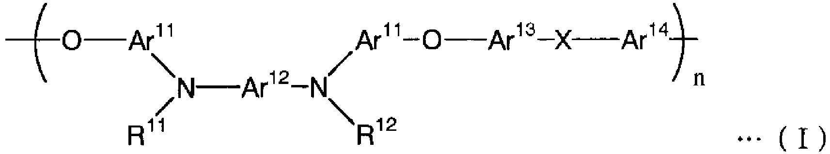
- polymeric compounds that have intramolecular hole-transporting sites include polymeric aromatic amines that contain tertiary aromatic amino groups as a constitutional unit of the backbone. More specific examples include hole-injecting/transporting materials having the structure shown in Formula (I) below as a repeating unit.
- the groups Ar 11 to Ar 14 represent divalent aromatic ring groups, each of which may have a substituent independently chosen, and the groups R 11 and R 12 represent monovalent aromatic ring groups, each of which may have a substituent independently chosen.
- X represents a direct bond or a binding group selected from the following groups.
- “Aromatic ring groups” include both “groups derived from aromatic hydrocarbon rings” and “groups derived from aromatic heterocyclic groups.”
- the groups A 11 to A 14 are preferably divalent benzene rings, naphthalene rings, anthracene rings, or groups derived from biphenyl, and more preferably groups derived from benzene rings, each of which may have a substituent independently chosen.
- substituents include halogen atoms; linear or branched alkyl chains with one to six carbons such as methyl groups and ethyl groups; alkenyl groups such as vinyl groups; linear or branched alkoxycarbonyl groups with two to seven carbons methoxycarbonyl groups and ethoxycarbonyl groups; linear or branched alkoxy groups with one to six carbons such as methoxy groups and ethoxy groups; aryloxy groups with six to twelve carbons such as phenoxy groups and benzyloxy groups; and dialkylamino groups that contains alkyl chains with one to six carbons such as diethylamino groups and diisopropylamino groups.
- alkyl groups with one to three carbons are preferable, and methyl groups are more preferable. In the most preferred case, however, all of the groups A 11 to A 14 are aromatic ring groups without any substitution.
- Examples of the groups R 11 and R 12 are preferably phenyl, naphthyl, anthryl, pyridyl, triazyl, pyrazyl, quinoxalyl, thienyl or biphenyl groups; more preferably phenyl, naphthyl or biphenyl groups; and most preferably phenyl groups, each of which may have a substituent independently chosen.
- substituents include the same groups as those described as possible substituents for aromatic ring groups of Ar 11 to Ar 14 .
- a hole-injecting/transporting material formed of a polymeric compound that has intramolecular hole-transporting sites is most preferably homopolymer with the structure shown in Formula (I), it is allowed that the material is copolymer containing any kinds of monomers with other structures. If the material is copolymer, it preferably contains at least 50 mol% of constitutional units shown in Formula (I), and more preferably, it contains at least 70 mol% of the constitutional units.
- a hole-injecting/transporting material formed of a polymeric compound may contain two or more kinds of structures shown in Formula (I) in one species. Furthermore, it is permissible to use two or more kinds of compounds containing the structure illustrated in Formula (I) in combination with each other.
- Examples of the hole-injecting/transporting material formed of a polymeric compound further include conjugated polymers, which are preferably polyfluorene, polypyrrole, polyaniline, polythiophene, or polyparaphenylene vinylene.
- aromatic amines to form a hole-injecting/transporting material include triarylamine-structured compounds, or can be selected from existing compounds for the formation of hole-injecting/transporting layers of organic electroluminescent devices.
- some known compounds can be used as the hole-injecting/transporting material.
- examples of such known compounds include aromatic diamines combined with tertiary aromatic amine units, such as 1,1-bis(4-di-p-tolylaminophenyl)cyclohexane (Japanese Unexamined Patent Application Publication No.
- aromatic amines wherein two or more tertiary amino groups are present and two or more condensed aromatic rings have been substituted by nitrogen atoms, represented by 4,4'-bis[N-(1-naphthyl)-N-phenylamino]biphenyl (Japanese Unexamined Patent Application Publication No. H5-234681 ); aromatic triamines that are derived from triphenylbenzenes and have a starburst structure ( U.S. Patent No. 4,923,774 ); aromatic diamines such as N,N'-diphenyl-N,N'-bis(3-methylphenyl)biphenyl-4,4'-diamine ( U.S.
- Patent No. 4,764,625 ⁇ , ⁇ , ⁇ ', ⁇ '-tetramethyl- ⁇ , ⁇ '-bis(4-di-p-tolylaminophenyl)-p-xylene
- Japanese Unexamined Patent Application Publication No. H3-269084 triphenylamine derivatives wherein each entire molecule has an asymmetric stereostructure
- Japanese Unexamined Patent Application Publication No. H4-129271 compounds wherein two or more pyrenyl groups have been substituted by aromatic diamino groups
- H4-364153 substances formed by combining tertiary amines via fluorene groups (Japanese Unexamined Patent Application Publication No. H5-25473 ); triamine compounds (Japanese Unexamined Patent Application Publication No. H5-239455 ); bisdipyridylaminobiphenyls (Japanese Unexamined Patent Application Publication No. H5-320634 ); N,N,N-triphenylamine derivatives (Japanese Unexamined Patent Application Publication No. H6-1972 ); aromatic diamines having a phenoxazine structure (Japanese Unexamined Patent Application Publication No.
- H7-138562 diaminophenylphenanthridine derivatives (Japanese Unexamined Patent Application Publication No. H7-252474 ); hydrazone compounds (Japanese Unexamined Patent Application Publication No. H2-311591 ); silazane compounds ( U.S. Patent No. 4,950,950 ); silanamine derivatives (Japanese Unexamined Patent Application Publication No. H6-49079 ); phosphamine derivatives (Japanese Unexamined Patent Application Publication No. H6-25659 ); and quinacridone compounds.
- These compounds may be used separately or in combination of two or more kinds.
- the amount of the hole-injecting/transporting material contained in the film-forming composition of the present invention is typically 0.05 wt% or more, and preferably 1 wt% or more. At the same time, it is typically 50 wt% or less, and preferably 30 wt% or less.
- Examples of electron-accepting compounds contained in the film-forming composition include one or more kinds of compounds selected from the group consisting of aromatic boron compounds and their salts, metal halides, Lewis acids, organic acids, salts formed of aromatic amines and metal halides, and salts formed of aromatic amines and Lewis acids. These electron-accepting compounds are mixed with the hole-injecting/ transporting material for use, thus improving conductivity of the hole-injecting layer by oxidization of the hole-injecting/ transporting material.
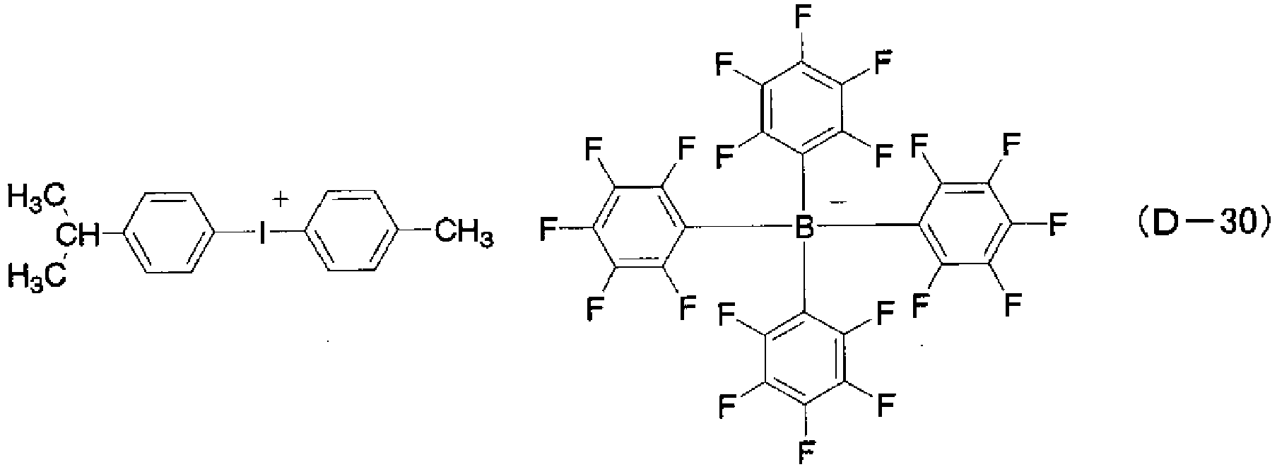
- (D-30) above is particularly preferable.
- specific examples of one or more compounds to be selected as the electron-accepting compound from the group consisting of metal halides, Lewis acids, organic acids, salts formed of aromatic amines and metal halides, and salts formed of aromatic amines and Lewis acids includes the following compounds.
- the ratio W e /W p where W e is the weight proportion of the electron-accepting compound relative to the film-forming composition of the present invention and Wp the weight proportion of the hole-injecting/ transporting material, is 0.001 or more, and preferably 0.01 or more. At the same time, it is typically 1 or less, and preferably 0.4 or less.
- the moisture content in the film-forming composition of the present invention is low as described above. More specifically, moisture contained in the film-forming composition is preferably 1 wt% or less, more preferably 0.1 wt% or less, and most preferably 0.05 wt% or less.
- the solvent, hole-injecting/transporting material and/or electron-accepting compound for preparation of the film-forming composition should be purified or dried for sufficient moisture removal as required, prior to use.
- additives such as a leveling agent or antifoaming agent may be optionally contained in the film-forming composition of the present invention.
- Binder resin described later, may also be added.
- FIGs. 1a to 1c are sectional views that illustrate an example configuration of an organic electroluminescent device with thin layers formed of the film-forming composition according to the present invention.
- the organic electroluminescent device 100a shown in FIG. 1a has the substrate 101 as well as the anode 102, the hole-injecting layer 103, the luminescent layer 105 and the cathode 107, each of which is sequentially laminated on the substrate 101.
- the substrate 101 is a support for the organic electroluminescent device 100a.
- Examples of material to form the substrate 101 include quartz plates, glass plates, metal plates, metal foil, plastic films and plastic sheets.
- glass plates and transparent plastic sheets made from polyesters, polymetacrylates, polycarbonates and polysulfones are preferable.
- the anode 102 is mounted on the substrate 101 to play a role of injecting a hole into the hole-injecting layer 103.
- Examples of material to form the anode 102 include metals such as aluminum, gold, silver, nickel, palladium and platinum; conductive metal oxides such as indium and/or tin oxides; metal halides such as copper iodide; carbon black; and conductive polymers such as poly(3-methylthiophene), polypyrrole and polyaniline.
- Typical examples of methods used to form the anode 102 include sputtering and vacuum deposition on the substrate 101; a method wherein fine particles of silver or other metals, fine particles of copper iodide or others, carbon black, fine particles of conductive metal oxides or fine particles of conductive polymers are dispersed in an appropriate binder resin solution followed by application onto the substrate 101; a method wherein a polymerized conductive thin film is directly formed on the substrate 101 via electrolytic polymerization; and a method wherein a conductive polymer solution is applied onto the substrate 101.
- visible transmittance of the anode 102 is preferably 60% or higher, and more preferably 80% or higher.
- Thickness of the anode 102 is typically 1000 nm or less, and preferably 500 nm or less, as well as typically 5 nm or more, and preferably 10 nm or more.
- the hole-injecting layer to be mounted on the anode 102 is preferably formed by a wet film-forming method using, preferably, the film-forming composition of the present invention. Because organic electroluminescent devices are formed by laminating many layers of organic compounds, it is very important to ensure the film characteristics are uniform.
- a certain technique is adopted from application techniques such as spin-coating and spraying, printing techniques such as an inkjet technique and screen technique, and other known film-forming techniques depending on characteristics of the material and substrate.
- the most suitable technique is the inkjet technique, which enables to form a uniform film on a desired area by fine patterning.
- the inkjet technique is especially useful to mount an organic layer on a certain area in the substrate surface where unevenness due to the presence of patterned electrodes or walls between imaging elements has been left.
- the hole-injecting layer 103 is formed by using a hole-injecting/transporting material and an electron-accepting compound capable of oxidizing this hole-injecting/transporting material. Thickness of the film of the thus-prepared hole-injecting layer 103 is typically 5 nm or more, and preferably 10 nm or more. At the same time, it is typically 1,000 nm or less, and preferably 500 nm or less.
- the luminescent layer 105 is mounted on the hole-injecting layer 103, and is formed of material that efficiently recombines electrons injected from the cathode 107 with holes transported from the hole-injecting layer 103 in an impressed electric field and efficiently emits light via the recombination.
- Examples of material to form the luminescent layer 105 include luminescent materials derived from small molecules such as 8-hydroxyquinoline complexes with aluminum or other metals, 10-hydroxybenzo[h]quinoline complexes with metals, bisstyrylbenzene derivatives, bisstyrylarylene derivatives, (2-hydroxyphenyl)benzothiazole complexes with metals and silole derivatives; and systems where luminescent material and electron-transporting material are blended in a polymeric compound such as poly(p-phenylenevinylene), poly[2-methoxy-5-(2-ethylhexyloxy)-1,4-phenylenevinylene), poly(3-alkylthiophene) and polyvinylcarbazole.
- a polymeric compound such as poly(p-phenylenevinylene), poly[2-methoxy-5-(2-ethylhexyloxy)-1,4-phenylenevinylene), poly(3-alkylthiophene) and poly
- doping naphthacene derivatives such as rubrene, quinacridone derivatives, condensed polycyclic aromatic rings such as perylene, or others to the host material, e.g., metal complexes including 8-hydroxyquinoline complexes with aluminum, so as to account for 0.1 to 10 wt%, can greatly improve the luminescent properties, in particular, driving stability of the device.
- Such material forms a thin film on the hole-injecting layer 103 by a vacuum deposition method or a wet film-forming method such as an inkjet film-forming technique.
- Thickness of the film of the thus-prepared luminescent layer 105 is typically 10 nm or more, and preferably 30 nm or more. At the same time, it is typically 200 nm or less, and preferably 100 nm or less.
- the cathode 107 plays a role of injecting electrons to the luminescent layer 105.
- Preferred material of the cathode 107 is metal that exhibits a low work function, including appropriate metals such as tin, magnesium, indium, calcium, aluminum and silver, or their alloy. Specific examples include electrodes of low-work function alloys such as magnesium-silver alloy, magnesium-indium alloy, and aluminum-lithium alloy. In general, thickness of the film of the cathode 107 is same as that of the anode 102.
- Laminating an air-resistant metal layer with a high work function on the anode 107 made from a low-work function metal for the purpose of protection is effective to improve stability of the device.
- metals such as aluminum, silver, copper, nickel, chrome, gold and platinum are used.
- insertion of the ultrathin insulating film (film thickness is 0.1 to 5 nm) derived from LiF, MgF 2 , Li 2 O or other compounds into the interface between the cathode 107 and the luminescent layer 105 can increase efficiency of the device.
- FIG. 1b is a diagram to illustrate a function-separated luminescent device.
- the hole-transporting layer 104 is inserted between the hole-injecting layer 103 and the luminescent layer 105 for improvement of the luminescent properties of the device, and other layers are in the same configuration as that of the organic electroluminescent device 100a shown in FIG. 1a .
- Material of the hole-transporting layer 104 requires high efficiency for receiving holes from the hole-injecting layer 103 and a capability to transport the received holes efficiently. Therefore, a low ionization potential, high hole-mobility, excellent stability and low incidence of impurities acting as a trap during manufacturing and use are necessary. In addition, it is advisable that the layer, which directly contacts the luminescent layer 105, does not contain any quenching substances.
- Examples of hole-injecting/transporting materials to form the hole-injecting layer 104 are the same as those illustrated for the hole-injecting/transporting material in the film-forming composition of the present invention.
- Polymeric materials such as polyvinylcarbazole, polyvinyltriphenylamine, and polyarylene ether sulfone containing tetraphenylbenzidine are also involved.
- the hole-transporting layer 104 is formed by laminating such a hole-injecting/transporting material on the hole-injecting layer 103 by a vacuum deposition method or a wet film-forming method such as an inkjet film-forming technique. Thickness of the film of the thus-prepared hole-transporting layer 104 is typically 10 nm or more, and preferably 30 nm or more. At the same time, it is typically 300 nm or less, and preferably 100 nm or less.
- FIG. 1c is a diagram to illustrate the other embodiment of the function-separated luminescent device.
- the electron-transporting layer 106 is inserted between the luminescent layer 105 and the cathode 107, and other layers are in the same configuration as that of the organic electroluminescent device 100b shown in FIG. 1b .
- Compounds used as the electron-transporting layer 106 requires ease of receiving electrons from the cathode 107 and better electron-transporting performance.
- electron-transporting material include 8-hydroxyquinoline complexes with aluminum, oxadiazole derivatives, systems in which these compounds are dispersed in resins such as polymethyl methacrylate (PMMA), phenanthroline derivatives, 2-t-butyl-9,10-N,N'-dicyanoanthraquinone diimine, n-type hydrogenated amorphous carbon silicon, n-type zinc sulfate, n-type zinc selenide.
- PMMA polymethyl methacrylate
- phenanthroline derivatives 2-t-butyl-9,10-N,N'-dicyanoanthraquinone diimine
- n-type hydrogenated amorphous carbon silicon n-type zinc sulfate
- n-type zinc selenide n-type zinc selenide.
- the electron-transporting layer 106 is formed by laminating such electron-transporting material on the luminescent layer 105 by a vacuum deposition method or a wet film-forming method such as an inkjet film-forming technique. Thickness of the film of the thus-prepared electron-transporting layer 106 is typically 5 nm or more, and preferably 10 nm or more. At the same time, it is typically 200 nm or less, and preferably 100 nm or less.
- the organic electroluminescent devices according to the present invention are not limited to those illustrated in the figures.
- the reverse structure of those shown in FIGs. 1a to 1c i.e., laminating the cathode 107, the luminescent layer 105, the hole-injecting layer 103, and the anode 102 sequentially on the substrate 101, is possible.
- the layer containing the hole-injecting/transporting material and the electron-accepting compound does not always have to be the hole-injecting layer 103 that contacts the anode 102.
- any desired layers may be inserted between individual layers shown in FIGs. 1a to 1c . Though not shown in the figures, it is also allowed to use wall-like structures of insulating material surrounding imaging elements, so-called "banks,” partitions dividing the cathode, nonlinear elements to activate the imaging elements, or others.
- the anode 102 is formed on the substrate 101 by sputtering, vacuum deposition or other methods. At least one of the hole-injecting layer 103 and the hole-transporting layer 104 is formed on the anode 102 by the inkjet film-forming technique using the composition of the present invention.
- the luminescent layer 105 is created by a vacuum deposition method or the inkjet film-forming method. If required, the electron-transporting layer 106 is prepared on the luminescent layer 105 by the vacuum deposition or the inkjet film-forming technique.
- the cathode 107 is mounted on the luminescent layer 105 or the electron-transporting layer 106.
- optional additives such as binder resin that does not trap holes or an agent to improve coating properties are added and dissolved in the predetermined amount of a hole-injecting/transporting material and an electron-accepting compound to form a coating liquid, i.e., the film-forming composition.
- This composition is applied onto the anode 102 by the inkjet film-forming technique and dried, resulting in the formation of at least one of the hole-injecting layer 103 and the hole-transporting layer 104.
- the content of the binder resin in the obtained film is preferably 50 wt% or less and more preferably 30 wt% or less, and most preferably, the film is substantially absent of the binder resin.
- adding a heating process after the inkjet film-forming and the drying processes can reduce the content of solvent remaining in the obtained film and the content of moisture, which has contaminated the film during the inkjet film-forming or other processes, thus improving device characteristics.
- a layer containing the hole-injecting/transporting material and the electron-accepting compound is formed by the inkjet film-forming technique and then, the substrate is heated with a hot plate, an oven or other means. To maximize the effect of the heating process, treatment at 100°C or higher is advisable. Typical heating time is approximately one minute to eight hours.
- the layer which contains the hole-injecting/transporting material and the electron-accepting compound and has been formed by the inkjet film-forming technique, has an even surface, solving the problem of a short-circuit during manufacturing of the device caused by surface roughness of the anode 102 such as ITO.
- the compound (I-3) illustrated above was used as a hole-injecting/transporting material, and the compound (D-30) illustrated above was used as an electron-accepting compound.
- the film-forming compositions were prepared by mixing constituents and solvents according to the formulations shown in Table 2. Hereinafter, the prepared film-forming compositions are simply called "ink.”
- Spraying of the prepared ink from a spray head nozzle was observed using the inkjet application apparatus equipped with a piezo-driven spray head as follows.
- the ink was continuously sprayed from the nozzle for five minutes and the spraying statuses after five minutes were observed.
- the number of defective nozzles which could not spray the ink due to nozzle clogging or failed to spray the ink properly due to angled spraying, was counted and evaluated as follows.
- VG Very Good
- the ratio of the number of defective nozzles to the total number of nozzles is lower than 10%.
- G (Good) The ratio of the number of defective nozzles to the total number of nozzles is 10% or higher, and lower than 50%.
- NG (Not Good): The ratio of the number of defective nozzles to the total number of nozzles is 50% or higher.
- Blur width means, as shown in FIG. 3 , the width of the region on the edge of the bank 203, where the film thickness of the ink 205 is uneven. Blur width was determined by observation with an optical microscope.
- the ink using single solvent, ethyl benzoate, in Reference Examples 5 and 14 as well as the ink using mixed solvents of ethyl benzoate and 2-phenoxyethyl acetate in Reference Examples 6 to 8, 14 to 18 and 20 to 23 provided favorable films.
- the reason for this may be the fact that the application liquid was resistant to dryness due to boiling points of at least 200°C and vapor pressures of 133.3 Pa (1 torr) or lower at room temperature of ethyl benzoate and 2-phenoxyethyl acetate, so that the coating liquid spread onto the imaging elements easily and had a good leveling property.
- the coating liquid containing mixed solvent of ethyl benzoate and 2-phenoxyethyl acetate provided a uniform film with little unevenness. This may be attributed to resistance to dryness and an excellent leveling property of the ink due to a very high boiling point of 2-phenoxyethyl acetate.
- the prepared ink was observed for its mist sprayed from the nozzle, as follows. After one-minute spraying of the ink from the nozzle, the nozzle was let stand for 30 minutes without spraying. Then the ink was sprayed once again, and the mist was observed and evaluated immediately after the re-spraying as follows. It should be noted the state of "proper mist" represents the case in which the shape of mist sprayed from the nozzle is completely conical. The clogged nozzle causes the shape of mist to be irregular, resulting in out-of-conical mist in many cases. G: Proper mist was observed from the beginning of re-spraying. NG: Clogging occurred.
- the ink prepared as described above was sprayed from the nozzle 206 of the spraying apparatus and applied onto the whole surface of the substrate 201, on which the anode 202 and the banks 203 had been formed in the same manner as Examples 1 to 4, 12 and 13 and Reference Examples 5 to 11 and 14 to 23, as shown in FIG. 5 .
- the ink and highpressure nitrogen gas are supplied into the nozzle 206, and then the ink is atomized by the nitrogen gas and sprayed from the nozzle.
- the substrate, onto which the ink had been applied in such a way was heated at 200°C until the ink was dry to obtain the thin film with approximately 130 nm of film thickness.
- the substrates on which the thin film was formed in this way were evaluated for the application status in the same manner as Examples 1 to 4, 12 and 13 and Reference Examples 5 to 11 and 14 to 23.
- composition for organic electrolumines cent devices Amount contained in the composition (wt%) Solvent composition (weight ratio) Spraying status Application status Blur width ( ⁇ m) Hole-injecting/transporting material Electron-accepting compound Ethyl benzoate 2-Phenoxyethyl acetate
- the excellent properties of the ink according to the present invention are effective also for application methods other than the inkjet and the spraying methods, e.g., printing methods such as flexographic printing, an application technique in which the ink is supplied from a slit-like nozzle such as blade coating, or spin coating.
Claims (23)
- Filmbildende Zusammensetzung, die eine Zusammensetzung ist, die verwendet wird, um einen Film einer lochinjizierenden/transportierenden Schicht einer organischen Elektrolumineszenzvorrichtung zu bilden, worin die filmbildende Zusammensetzung ein lochinjizierendes/transportierendes Material, eine elektronenaufnehmende Verbindung und eine Flüssigkeit enthält, in der das Material und die Verbindung gelöst worden sind;
worin die Flüssigkeit ein erstes Lösungsmittel enthält, dessen Molekül einen aromatischen Ring und/oder einen aliphatischen Ring und ein Sauerstoffatom aufweist und das entweder einen Siedepunkt von mindestens 200°C oder einen Dampfdruck von 133,3 Pa (1 Torr) oder kleiner bei 25°C aufweist; und
die Menge des ersten Lösungsmittels, die in der Zusammensetzung enthalten ist, 3 Gew.-% oder mehr beträgt, dadurch gekennzeichnet, dass die Flüssigkeit ferner ein zweites Lösungsmittel enthält, das einen aromatischen Ring und/oder einen aliphatischen Ring und ein Sauerstoffatom in seinem Molekül aufweist und einen Siedepunkt von niedriger als 200°C und einen Dampfdruck von größer als 133,3 Pa (1 Torr) bei 25°C aufweist; und worin das Verhältnis W2/W1, wobei W2 der Gewichtsanteil des zweiten Lösungsmittels und W1 der Gewichtsanteil des ersten Lösungsmittels ist, 1 bis 20 beträgt. - Filmbildende Zusammensetzung gemäß Anspruch 1, worin das Verhältnis W2/W1 1 bis 2,5 beträgt.
- Filmbildende Zusammensetzung gemäß Anspruch 1, worin das erste Lösungsmittel ein aromatischer Ester ist.
- Filmbildende Zusammensetzung gemäß Anspruch 3, worin der aromatische Ester ein Benzoat ist.
- Filmbildende Zusammensetzung gemäß Anspruch 4, worin das Benzoat Ethylbenzoat ist.
- Filmbildende Zusammensetzung gemäß Anspruch 1, wobei die Flüssigkeit zwei oder mehr Arten des ersten Lösungsmittels enthält.
- Filmbildende Zusammensetzung gemäß Anspruch 6, worin ein erstes Lösungsmittel ein erstes Lösungsmittel mit einer höheren Verdampfbarkeit ist und ein anderes erstes Lösungsmittel ein erstes Lösungsmittel mit einer niedrigeren Verdampfbarkeit und entweder einem höheren Siedepunkt oder einem niedrigeren Dampfdruck bei 25°C ist; und
ein Verhältnis Wa/Wb, wobei Wa der Gewichtsanteil des ersten Lösungsmittels mit einer höheren Verdampfbarkeit ist und Wb der Gewichtsanteil des ersten Lösungsmittels mit einer niedrigeren Verdampfbarkeit ist, 1 bis 20 beträgt. - Filmbildende Zusammensetzung gemäß Anspruch 7, worin das Verhältnis Wa/Wb 1 bis 2,5 beträgt.
- Filmbildende Zusammensetzung gemäß Anspruch 7, wobei das erste Lösungsmittel mit höherer Verdampfbarkeit ein Benzoat ist und das erste Lösungsmittel mit geringerer Verdampfbarkeit ein Acetat mit einem aromatischen Ring ist.
- Filmbildende Zusammensetzung nach Anspruch 9, wobei das Benzoat Ethylbenzoat ist und das Acetat mit einem aromatischen Ring 2-Phenoxyethylacetat ist.
- Filmbildende Zusammensetzung gemäß Anspruch 1, wobei das lochinjizierende/transportierende Material eine aromatische Aminverbindung ist und die elektronenaufnehmende Verbindung eine aromatische Borverbindung und/oder deren Salz ist.
- Filmbildende Zusammensetzung gemäß Anspruch 1, wobei die in der Zusammensetzung enthaltene Feuchtigkeit 1 Gew.-% oder weniger beträgt.
- Filmbildende Zusammensetzung gemäß Anspruch 1, wobei das lochinjizierende/transportierende Material eine polymere Verbindung mit intramolekularen Lochtransportstellen ist.
- Filmbildende Zusammensetzung gemäß Anspruch 13, worin die polymere Verbindung ein polymeres aromatisches Amin ist, das tertiäre aromatische Aminogruppen als eine Aufbaueinheit seines Gerüsts enthält.
- Filmbildende Zusammensetzung gemäß Anspruch 14, worin die polymere Verbindung die in Formel (I) gezeigte Struktur als Aufbaueinheit aufweist

- Filmbildende Zusammensetzung gemäß Anspruch 15, worin die in Formel (I) gezeigte Struktur eine der folgenden (I-1), (I-2), (I-3) und (I-4) ist


- Filmbildende Zusammensetzung gemäß Anspruch 16, wobei die in Formel (I) gezeigte Struktur (I-3) ist.
- Filmbildende Zusammensetzung gemäß Anspruch 1, worin die Menge des in der filmbildenden Zusammensetzung enthaltenen lochinjizierenden/transportierenden Materials 0,05 bis 50 Gew.-% beträgt.
- Filmbildende Zusammensetzung nach Anspruch 11, wobei die aromatische Borverbindung und/oder ihr Salz nachstehendes (D-30) ist
- Filmbildende Zusammensetzung gemäß Anspruch 1, worin ein Verhältnis We/Wp, wobei We der Gewichtsanteil der elektronenaufnehmenden Verbindung, bezogen auf die filmbildende Zusammensetzung, und Wp der Gewichtsanteil des lochinjizierenden/transportierenden Materials, bezogen auf die filmbildende Zusammensetzung, ist, 0,001 bis 1 beträgt.
- Filmbildende Zusammensetzung gemäß Anspruch 1, wobei das zweite Lösungsmittel mindestens eines vonaromatischem Ether;alizyklischem Keton; undalizyklischem Alkoholist.
- Filmbildende Zusammensetzung gemäß Anspruch 1, wobei das zweite Lösungsmittel Anisol und/oder Cyclohexanon ist.
- Verwendung der filmbildenden Zusammensetzung gemäß Anspruch 1 zur Bildung einer Lochinjizierenden/transportierenden Schicht einer organischen Elektrolumineszenzvorrichtung (100a, 100b, 100c).
Applications Claiming Priority (2)
| Application Number | Priority Date | Filing Date | Title |
|---|---|---|---|
| JP2005037902 | 2005-02-15 | ||
| PCT/JP2006/302118 WO2006087945A1 (ja) | 2005-02-15 | 2006-02-08 | 成膜用組成物及び有機電界発光素子 |
Publications (4)
| Publication Number | Publication Date |
|---|---|
| EP1850368A1 EP1850368A1 (de) | 2007-10-31 |
| EP1850368A4 EP1850368A4 (de) | 2012-04-04 |
| EP1850368B1 EP1850368B1 (de) | 2013-04-24 |
| EP1850368B2 true EP1850368B2 (de) | 2021-04-21 |
Family
ID=36916353
Family Applications (1)
| Application Number | Title | Priority Date | Filing Date |
|---|---|---|---|
| EP06713261.3A Active EP1850368B2 (de) | 2005-02-15 | 2006-02-08 | Filmbildende zusammensetzung und organisches elektrolumineszenzierendes bauelement |
Country Status (7)
| Country | Link |
|---|---|
| US (1) | US8053973B2 (de) |
| EP (1) | EP1850368B2 (de) |
| JP (4) | JP5194787B2 (de) |
| KR (2) | KR101415586B1 (de) |
| CN (1) | CN100573965C (de) |
| TW (1) | TWI396703B (de) |
| WO (1) | WO2006087945A1 (de) |
Families Citing this family (36)
| Publication number | Priority date | Publication date | Assignee | Title |
|---|---|---|---|---|
| US20060182993A1 (en) * | 2004-08-10 | 2006-08-17 | Mitsubishi Chemical Corporation | Compositions for organic electroluminescent device and organic electroluminescent device |
| JP5225557B2 (ja) * | 2005-05-20 | 2013-07-03 | 住友化学株式会社 | 芳香族エーテル化合物含有組成物及びそれを用いた高分子発光素子 |
| EP2960299A1 (de) * | 2005-05-20 | 2015-12-30 | Sumitomo Chemical Co., Ltd. | Polymerzusammensetzung und polymere lichtemittierende vorrichtung damit |
| JP2012197453A (ja) * | 2005-05-20 | 2012-10-18 | Sumitomo Chemical Co Ltd | 芳香族エーテル化合物含有組成物及びそれを用いた高分子発光素子 |
| JP2009540574A (ja) * | 2006-06-05 | 2009-11-19 | イー・アイ・デュポン・ドウ・ヌムール・アンド・カンパニー | Oled印刷の分野における有機活性材料を堆積するための液体組成物 |
| JP2008294401A (ja) * | 2007-04-25 | 2008-12-04 | Mitsubishi Chemicals Corp | 有機電界発光素子用組成物、有機電界発光素子および有機電界発光素子の製造方法 |
| JP5259139B2 (ja) * | 2007-08-31 | 2013-08-07 | 三菱化学株式会社 | 有機電界発光素子用組成物、有機電界発光素子および有機電界発光素子の製造方法 |
| US20090130296A1 (en) * | 2007-11-15 | 2009-05-21 | Universal Display Corporation | Fabrication of Organic Electronic Devices by Ink-Jet Printing at Low Temperatures |
| CN107266679B (zh) * | 2008-02-15 | 2021-07-06 | 三菱化学株式会社 | 共轭聚合物、有机场致发光元件材料、有机场致发光元件用组合物、有机场致发光元件 |
| GB2462410B (en) * | 2008-07-21 | 2011-04-27 | Cambridge Display Tech Ltd | Compositions and methods for manufacturing light-emissive devices |
| JP5658161B2 (ja) * | 2008-10-27 | 2015-01-21 | プレックストロニクス インコーポレーティッド | ポリアリールアミンケトン |
| GB2466843A (en) * | 2009-01-12 | 2010-07-14 | Cambridge Display Tech Ltd | Interlayer formulation for flat films |
| EP2962338B1 (de) * | 2009-06-17 | 2020-02-05 | Universal Display Corporation | Flüssigkeitszusammensetzungen für den tintenstrahlbedruck organischer schichten und andere verwendungsarten |
| JP2013503234A (ja) * | 2009-08-28 | 2013-01-31 | エルジー・ケム・リミテッド | 導電性金属インク組成物および導電性パターンの形成方法 |
| KR101646799B1 (ko) * | 2010-07-01 | 2016-08-08 | 가부시키가이샤 제이올레드 | 유기 발광 소자용 잉크, 유기 발광 소자의 제조 방법, 유기 표시 패널, 유기 표시 장치, 유기 발광 장치, 잉크, 기능층의 형성 방법, 및 유기 발광 소자 |
| DE102010056519A1 (de) * | 2010-12-27 | 2012-06-28 | Heliatek Gmbh | Optoelektronisches Bauelement mit dotierten Schichten |
| JP6015073B2 (ja) * | 2012-04-02 | 2016-10-26 | セイコーエプソン株式会社 | 機能層形成用インク、発光素子の製造方法 |
| JP6041513B2 (ja) | 2012-04-03 | 2016-12-07 | キヤノン株式会社 | 画像処理装置、画像処理方法及びプログラム |
| JP6098042B2 (ja) * | 2012-04-24 | 2017-03-22 | 日立化成株式会社 | 色変化防止剤、該色変化防止剤を含むインク組成物、該インク組成物を用いて形成した有機薄膜、有機エレクトロニクス素子、有機エレクトロルミネセンス素子、表示素子、照明装置、及び表示装置 |
| GB201210858D0 (en) * | 2012-06-19 | 2012-08-01 | Cambridge Display Tech Ltd | Method |
| TWI483902B (zh) * | 2013-04-03 | 2015-05-11 | 國立臺灣大學 | 製作參雜金屬離子之硫化鋅奈米粒子的方法以及應用其進行光致發暖白光的方法 |
| WO2015087961A1 (ja) | 2013-12-12 | 2015-06-18 | 三菱化学株式会社 | イリジウム錯体化合物、該化合物の製造方法、該化合物を含む組成物、有機電界発光素子、表示装置及び照明装置 |
| JP6638186B2 (ja) * | 2014-12-02 | 2020-01-29 | セイコーエプソン株式会社 | 成膜用インクおよび成膜方法 |
| JP6638187B2 (ja) * | 2014-12-02 | 2020-01-29 | セイコーエプソン株式会社 | 成膜用インクおよび成膜方法 |
| CN107210380B (zh) | 2015-01-26 | 2019-06-28 | 住友化学株式会社 | 组合物和使用该组合物的发光元件 |
| WO2016186012A1 (ja) * | 2015-05-19 | 2016-11-24 | 住友化学株式会社 | 組成物及びそれを用いた発光素子 |
| WO2017102048A1 (en) * | 2015-12-15 | 2017-06-22 | Merck Patent Gmbh | Esters containing aromatic groups as solvents for organic electronic formulations |
| WO2017216128A1 (en) | 2016-06-17 | 2017-12-21 | Merck Patent Gmbh | Formulation of an organic functional material |
| JP7082984B2 (ja) * | 2017-02-20 | 2022-06-09 | ノヴァレッド ゲーエムベーハー | 電子半導体デバイスおよびその電子半導体デバイスの製造方法および化合物 |
| KR102413781B1 (ko) * | 2017-12-12 | 2022-06-27 | 주식회사 엘지화학 | 잉크 조성물 및 유기 발광 소자 제조방법 |
| KR102285565B1 (ko) * | 2017-12-12 | 2021-08-04 | 주식회사 엘지화학 | 잉크 조성물 및 유기 발광 소자 제조방법 |
| KR102316066B1 (ko) * | 2018-07-27 | 2021-10-21 | 주식회사 엘지화학 | 잉크 조성물, 이를 이용한 유기 발광 소자 및 이의 제조방법 |
| CN110791149A (zh) * | 2018-08-02 | 2020-02-14 | 中国科学院苏州纳米技术与纳米仿生研究所 | 气溶胶打印oled空穴传输层的墨水、其制法及应用 |
| KR102413612B1 (ko) * | 2018-08-31 | 2022-06-24 | 주식회사 엘지화학 | 유기 발광 소자용 잉크 조성물 |
| KR102651100B1 (ko) * | 2018-10-29 | 2024-03-22 | 주식회사 엘지화학 | 유기 발광 소자용 잉크 조성물 |
| WO2020113574A1 (zh) * | 2018-12-07 | 2020-06-11 | 深圳市柔宇科技有限公司 | Oled器件及其制备方法、旋涂成膜的原料溶液 |
Citations (4)
| Publication number | Priority date | Publication date | Assignee | Title |
|---|---|---|---|---|
| EP1134269A2 (de) † | 2000-03-16 | 2001-09-19 | Sumitomo Chemical Company, Limited | Polymerisches fluoreszentes Material, Lösung dieses polymerischen fluoreszenten Materials, und lumineszentes Polymergerät worin dieses Material eingesetzt wird |
| WO2002077060A1 (de) † | 2001-03-24 | 2002-10-03 | Covion Organic Semiconductors Gmbh | Konjugierte polymere enthaltend spirobifluoren-einheiten und fluoren-einheiten und deren verwendung |
| DE10337077A1 (de) † | 2003-08-12 | 2005-03-10 | Covion Organic Semiconductors | Konjugierte Copolymere, deren Darstellung und Verwendung |
| EP1716604A1 (de) † | 2004-02-18 | 2006-11-02 | Merck Patent GmbH | Lösungen organischer halbleiter |
Family Cites Families (36)
| Publication number | Priority date | Publication date | Assignee | Title |
|---|---|---|---|---|
| JP3643452B2 (ja) * | 1995-11-10 | 2005-04-27 | ケミプロ化成株式会社 | 芳香族ジアミン含有ポリエーテルおよびそれを用いた有機el素子 |
| WO1999012395A1 (fr) | 1997-09-02 | 1999-03-11 | Seiko Epson Corporation | Procede de fabrication d'un element electroluminescent organique et element electroluminescent organique correspondant |
| JP2000106278A (ja) | 1997-09-02 | 2000-04-11 | Seiko Epson Corp | 有機el素子の製造方法及び有機el素子 |
| JP3748491B2 (ja) | 1998-03-27 | 2006-02-22 | 出光興産株式会社 | 有機エレクトロルミネッセンス素子 |
| JP4058842B2 (ja) | 1998-05-13 | 2008-03-12 | 三菱化学株式会社 | 有機電界発光素子 |
| JP4486261B2 (ja) * | 1999-03-29 | 2010-06-23 | セイコーエプソン株式会社 | 組成物、膜の製造方法、並びに機能素子及びその製造方法 |
| JP2001085155A (ja) * | 1999-09-13 | 2001-03-30 | Matsushita Electric Ind Co Ltd | 有機エレクトロルミネッセンス素子及びこれを用いた有機エレクトロルミネッセンス装置 |
| JP4747427B2 (ja) * | 2000-03-16 | 2011-08-17 | 住友化学株式会社 | 高分子蛍光体およびそれを用いた高分子発光素子 |
| JP4144192B2 (ja) | 2000-05-29 | 2008-09-03 | 三菱化学株式会社 | 有機電界発光素子の製造方法 |
| JP2001342364A (ja) * | 2000-06-02 | 2001-12-14 | Konica Corp | 感熱転写記録材料、感熱転写記録方法、色素と金属イオン含有化合物との混合物、カラートナー、有機エレクトロルミネッセンス素子、インク、光記録媒体及びカラーフィルター |
| JP3896876B2 (ja) | 2001-03-12 | 2007-03-22 | セイコーエプソン株式会社 | 膜の製造方法、機能素子の製造方法、電気光学装置の製造方法、及び電子機器の製造方法 |
| US6787063B2 (en) | 2001-03-12 | 2004-09-07 | Seiko Epson Corporation | Compositions, methods for producing films, functional elements, methods for producing functional elements, methods for producing electro-optical devices and methods for producing electronic apparatus |
| JP4023204B2 (ja) | 2001-05-02 | 2007-12-19 | 淳二 城戸 | 有機電界発光素子 |
| US6597012B2 (en) | 2001-05-02 | 2003-07-22 | Junji Kido | Organic electroluminescent device |
| JP3996036B2 (ja) * | 2001-11-19 | 2007-10-24 | 三菱化学株式会社 | 芳香族ジアミン含有高分子化合物およびそれを用いる有機電界発光素子 |
| KR20020025918A (ko) | 2002-02-15 | 2002-04-04 | 박병주 | 습식 공정으로 제작된 유기 반도체 디바이스 및 유기전계발광 소자 |
| JP2004002740A (ja) * | 2002-03-22 | 2004-01-08 | Mitsubishi Chemicals Corp | 高分子化合物、1,4−フェニレンジアミン誘導体、電荷輸送材料、有機電界発光素子材料および有機電界発光素子 |
| JP4396115B2 (ja) * | 2002-03-22 | 2010-01-13 | 三菱化学株式会社 | 高分子化合物、1,4−フェニレンジアミン誘導体、電荷輸送材料、有機電界発光素子材料および有機電界発光素子 |
| JP2003303692A (ja) * | 2002-04-09 | 2003-10-24 | Jsr Corp | インクジェット方式による有機el表示素子の絶縁膜形成に用いる感放射線性樹脂組成物、それから形成された有機el表示素子の絶縁膜、および有機el表示素子 |
| JP3918617B2 (ja) * | 2002-04-16 | 2007-05-23 | 株式会社日立製作所 | 有機elディスプレイおよびその製造方法 |
| US20040004433A1 (en) | 2002-06-26 | 2004-01-08 | 3M Innovative Properties Company | Buffer layers for organic electroluminescent devices and methods of manufacture and use |
| JP2004231938A (ja) * | 2002-09-13 | 2004-08-19 | Sekisui Chem Co Ltd | 有機el素子封止用光硬化性接着剤組成物、有機el素子の封止方法および有機el素子 |
| JP2004119351A (ja) | 2002-09-30 | 2004-04-15 | Dainippon Screen Mfg Co Ltd | 有機el塗布装置 |
| JP2004179144A (ja) | 2002-09-30 | 2004-06-24 | Seiko Epson Corp | 塗布液組成物および薄膜形成方法 |
| JP2004134213A (ja) * | 2002-10-10 | 2004-04-30 | Toppan Printing Co Ltd | 高分子el素子用塗布液および高分子el素子 |
| JP2004204114A (ja) | 2002-12-26 | 2004-07-22 | Dainippon Printing Co Ltd | インクジェット用インク組成物 |
| JP4424026B2 (ja) * | 2003-04-07 | 2010-03-03 | 三菱化学株式会社 | 2,7−ジアミノナフタレン化合物、電荷輸送材料、有機電界発光素子材料、および有機電界発光素子 |
| JP2004355913A (ja) * | 2003-05-28 | 2004-12-16 | Seiko Epson Corp | 有機エレクトロルミネッセンス装置の製造方法 |
| JP2004362930A (ja) | 2003-06-04 | 2004-12-24 | Mitsubishi Chemicals Corp | 有機電界発光素子、電荷輸送材料、及び有機電界発光素子材料 |
| JP4818592B2 (ja) | 2003-07-01 | 2011-11-16 | オリンパス株式会社 | 顕微鏡システム、顕微鏡画像表示システム、観察体画像表示方法、及びプログラム |
| JP4415582B2 (ja) * | 2003-07-02 | 2010-02-17 | 三菱化学株式会社 | 有機電界発光素子およびその製造方法 |
| JP2005093427A (ja) | 2003-08-14 | 2005-04-07 | Mitsubishi Chemicals Corp | 有機電界発光素子用組成物及び有機電界発光素子の製造方法 |
| JP2005093428A (ja) | 2003-08-14 | 2005-04-07 | Mitsubishi Chemicals Corp | 有機電界発光素子用組成物及び有機電界発光素子 |
| JP4084271B2 (ja) | 2003-09-12 | 2008-04-30 | 株式会社リコー | 用紙後処理装置 |
| EP2918590A1 (de) | 2004-03-11 | 2015-09-16 | Mitsubishi Chemical Corporation | Zusammensetzung für eine ladungstransportfolie und ionenzusammensetzung, ladetransportfolie und organische elektrolumineszenzvorrichtung damit, und herstellungsverfahren der organischen elektrolumineszenzvorrichtung und herstellungsverfahren der ladungstransportfolie |
| US20060182993A1 (en) | 2004-08-10 | 2006-08-17 | Mitsubishi Chemical Corporation | Compositions for organic electroluminescent device and organic electroluminescent device |
-
2006
- 2006-02-08 KR KR1020127018157A patent/KR101415586B1/ko active IP Right Grant
- 2006-02-08 US US11/815,669 patent/US8053973B2/en active Active
- 2006-02-08 CN CNB2006800049628A patent/CN100573965C/zh active Active
- 2006-02-08 JP JP2007503622A patent/JP5194787B2/ja active Active
- 2006-02-08 EP EP06713261.3A patent/EP1850368B2/de active Active
- 2006-02-08 KR KR1020077018685A patent/KR101237264B1/ko active IP Right Grant
- 2006-02-08 WO PCT/JP2006/302118 patent/WO2006087945A1/ja active Application Filing
- 2006-02-15 TW TW095104990A patent/TWI396703B/zh active
-
2011
- 2011-12-16 JP JP2011276095A patent/JP5720559B2/ja active Active
-
2014
- 2014-12-18 JP JP2014256297A patent/JP6044625B2/ja active Active
-
2015
- 2015-11-20 JP JP2015227842A patent/JP6172243B2/ja active Active
Patent Citations (4)
| Publication number | Priority date | Publication date | Assignee | Title |
|---|---|---|---|---|
| EP1134269A2 (de) † | 2000-03-16 | 2001-09-19 | Sumitomo Chemical Company, Limited | Polymerisches fluoreszentes Material, Lösung dieses polymerischen fluoreszenten Materials, und lumineszentes Polymergerät worin dieses Material eingesetzt wird |
| WO2002077060A1 (de) † | 2001-03-24 | 2002-10-03 | Covion Organic Semiconductors Gmbh | Konjugierte polymere enthaltend spirobifluoren-einheiten und fluoren-einheiten und deren verwendung |
| DE10337077A1 (de) † | 2003-08-12 | 2005-03-10 | Covion Organic Semiconductors | Konjugierte Copolymere, deren Darstellung und Verwendung |
| EP1716604A1 (de) † | 2004-02-18 | 2006-11-02 | Merck Patent GmbH | Lösungen organischer halbleiter |
Also Published As
| Publication number | Publication date |
|---|---|
| KR101415586B1 (ko) | 2014-08-06 |
| WO2006087945A1 (ja) | 2006-08-24 |
| JP5720559B2 (ja) | 2015-05-20 |
| US8053973B2 (en) | 2011-11-08 |
| JPWO2006087945A1 (ja) | 2008-07-03 |
| KR101237264B1 (ko) | 2013-02-27 |
| EP1850368A1 (de) | 2007-10-31 |
| EP1850368B1 (de) | 2013-04-24 |
| CN100573965C (zh) | 2009-12-23 |
| KR20120096075A (ko) | 2012-08-29 |
| TW200640993A (en) | 2006-12-01 |
| TWI396703B (zh) | 2013-05-21 |
| JP2015092602A (ja) | 2015-05-14 |
| CN101120459A (zh) | 2008-02-06 |
| JP6172243B2 (ja) | 2017-08-02 |
| JP6044625B2 (ja) | 2016-12-14 |
| US20090033208A1 (en) | 2009-02-05 |
| JP2016054311A (ja) | 2016-04-14 |
| JP2012084909A (ja) | 2012-04-26 |
| EP1850368A4 (de) | 2012-04-04 |
| KR20070103452A (ko) | 2007-10-23 |
| JP5194787B2 (ja) | 2013-05-08 |
Similar Documents
| Publication | Publication Date | Title |
|---|---|---|
| EP1850368B2 (de) | Filmbildende zusammensetzung und organisches elektrolumineszenzierendes bauelement | |
| US20090309070A1 (en) | Compositions for organic electroluminescent device and organic electroluminescent device | |
| KR101751873B1 (ko) | 유기층 잉크 젯 프린팅에 사용되거나 또는 기타 용도로 사용되는 액체 조성물 | |
| KR101618395B1 (ko) | 유기 층들의 잉크젯 인쇄 또는 다른 용도를 위한 액체 조성물 | |
| CN107532022B (zh) | 适用于有机电子器件的非水性组合物 | |
| US20070228364A1 (en) | Compositions comprising novel copolymers and electronic devices made with such compositions | |
| US20090239045A1 (en) | Charge-transporting varnish for spray or ink jet application | |
| EP2431354A1 (de) | Zusammensetzungen mit neuen Verbindungen und elektronische Vorrichtungen aus den Zusammensetzungen | |
| JP5259139B2 (ja) | 有機電界発光素子用組成物、有機電界発光素子および有機電界発光素子の製造方法 | |
| KR20170106503A (ko) | 모노아민 화합물, 전하 수송 재료, 전하 수송막용 조성물, 유기 전계 발광 소자, 유기 el 표시 장치 및 유기 el 조명 | |
| EP1976822B1 (de) | Aromatisches Amin enthaltende Zusammensetzungen und damit hergestellte elektronische Bauteile | |
| JP2005093428A (ja) | 有機電界発光素子用組成物及び有機電界発光素子 | |
| JP4375502B2 (ja) | 発光素子 | |
| JP5120427B2 (ja) | 有機電界発光素子の製造方法及び有機電界発光素子 | |
| KR20240016268A (ko) | 방향족 화합물 및 유기 전계 발광 소자 |
Legal Events
| Date | Code | Title | Description |
|---|---|---|---|
| PUAI | Public reference made under article 153(3) epc to a published international application that has entered the european phase |
Free format text: ORIGINAL CODE: 0009012 |
|
| 17P | Request for examination filed |
Effective date: 20070809 |
|
| AK | Designated contracting states |
Kind code of ref document: A1 Designated state(s): DE |
|
| RIC1 | Information provided on ipc code assigned before grant |
Ipc: H01L 51/50 20060101AFI20071204BHEP |
|
| RAP1 | Party data changed (applicant data changed or rights of an application transferred) |
Owner name: MITSUBISHI CHEMICAL CORPORATION Owner name: PIONEER CORPORATION |
|
| DAX | Request for extension of the european patent (deleted) | ||
| RBV | Designated contracting states (corrected) |
Designated state(s): DE |
|
| RAP1 | Party data changed (applicant data changed or rights of an application transferred) |
Owner name: MITSUBISHI CHEMICAL CORPORATION Owner name: PIONEER CORPORATION |
|
| A4 | Supplementary search report drawn up and despatched |
Effective date: 20120305 |
|
| RIC1 | Information provided on ipc code assigned before grant |
Ipc: H01L 51/50 20060101AFI20120228BHEP |
|
| RAP1 | Party data changed (applicant data changed or rights of an application transferred) |
Owner name: PIONEER CORPORATION Owner name: MITSUBISHI CHEMICAL CORPORATION |
|
| REG | Reference to a national code |
Ref country code: DE Ref legal event code: R079 Ref document number: 602006035866 Country of ref document: DE Free format text: PREVIOUS MAIN CLASS: H01L0021000000 Ipc: H01L0051560000 |
|
| RIC1 | Information provided on ipc code assigned before grant |
Ipc: H01L 51/56 20060101AFI20121002BHEP |
|
| GRAJ | Information related to disapproval of communication of intention to grant by the applicant or resumption of examination proceedings by the epo deleted |
Free format text: ORIGINAL CODE: EPIDOSDIGR1 |
|
| GRAP | Despatch of communication of intention to grant a patent |
Free format text: ORIGINAL CODE: EPIDOSNIGR1 |
|
| GRAS | Grant fee paid |
Free format text: ORIGINAL CODE: EPIDOSNIGR3 |
|
| GRAA | (expected) grant |
Free format text: ORIGINAL CODE: 0009210 |
|
| STAA | Information on the status of an ep patent application or granted ep patent |
Free format text: STATUS: THE PATENT HAS BEEN GRANTED |
|
| AK | Designated contracting states |
Kind code of ref document: B1 Designated state(s): DE |
|
| REG | Reference to a national code |
Ref country code: DE Ref legal event code: R081 Ref document number: 602006035866 Country of ref document: DE Owner name: PIONEER CORP., JP Free format text: FORMER OWNERS: MITSUBISHI CHEMICAL CORP., TOKIO/TOKYO, JP; PIONEER DESIGN CORP., TOKIO/TOKYO, JP Ref country code: DE Ref legal event code: R081 Ref document number: 602006035866 Country of ref document: DE Owner name: MITSUBISHI CHEMICAL CORPORATION, JP Free format text: FORMER OWNERS: MITSUBISHI CHEMICAL CORP., TOKIO/TOKYO, JP; PIONEER DESIGN CORP., TOKIO/TOKYO, JP |
|
| REG | Reference to a national code |
Ref country code: DE Ref legal event code: R096 Ref document number: 602006035866 Country of ref document: DE Effective date: 20130620 |
|
| PLBI | Opposition filed |
Free format text: ORIGINAL CODE: 0009260 |
|
| PLAX | Notice of opposition and request to file observation + time limit sent |
Free format text: ORIGINAL CODE: EPIDOSNOBS2 |
|
| 26 | Opposition filed |
Opponent name: MERCK PATENT GMBH Effective date: 20140124 |
|
| REG | Reference to a national code |
Ref country code: DE Ref legal event code: R026 Ref document number: 602006035866 Country of ref document: DE Effective date: 20140124 |
|
| PLAF | Information modified related to communication of a notice of opposition and request to file observations + time limit |
Free format text: ORIGINAL CODE: EPIDOSCOBS2 |
|
| PLBB | Reply of patent proprietor to notice(s) of opposition received |
Free format text: ORIGINAL CODE: EPIDOSNOBS3 |
|
| PLCK | Communication despatched that opposition was rejected |
Free format text: ORIGINAL CODE: EPIDOSNREJ1 |
|
| APAH | Appeal reference modified |
Free format text: ORIGINAL CODE: EPIDOSCREFNO |
|
| APBM | Appeal reference recorded |
Free format text: ORIGINAL CODE: EPIDOSNREFNO |
|
| APBP | Date of receipt of notice of appeal recorded |
Free format text: ORIGINAL CODE: EPIDOSNNOA2O |
|
| APBQ | Date of receipt of statement of grounds of appeal recorded |
Free format text: ORIGINAL CODE: EPIDOSNNOA3O |
|
| APAH | Appeal reference modified |
Free format text: ORIGINAL CODE: EPIDOSCREFNO |
|
| RAP2 | Party data changed (patent owner data changed or rights of a patent transferred) |
Owner name: PIONEER CORPORATION Owner name: MITSUBISHI CHEMICAL CORPORATION |
|
| RAP2 | Party data changed (patent owner data changed or rights of a patent transferred) |
Owner name: MITSUBISHI CHEMICAL CORPORATION Owner name: PIONEER CORPORATION |
|
| REG | Reference to a national code |
Ref country code: DE Ref legal event code: R082 Ref document number: 602006035866 Country of ref document: DE Representative=s name: HOFFMANN - EITLE PATENT- UND RECHTSANWAELTE PA, DE Ref country code: DE Ref legal event code: R081 Ref document number: 602006035866 Country of ref document: DE Owner name: PIONEER CORP., JP Free format text: FORMER OWNERS: MITSUBISHI CHEMICAL CORP., TOKIO/TOKYO, JP; PIONEER CORP., TOKIO/TOKYO, JP Ref country code: DE Ref legal event code: R081 Ref document number: 602006035866 Country of ref document: DE Owner name: MITSUBISHI CHEMICAL CORPORATION, JP Free format text: FORMER OWNERS: MITSUBISHI CHEMICAL CORP., TOKIO/TOKYO, JP; PIONEER CORP., TOKIO/TOKYO, JP |
|
| RAP2 | Party data changed (patent owner data changed or rights of a patent transferred) |
Owner name: MITSUBISHI CHEMICAL CORPORATION Owner name: PIONEER CORPORATION |
|
| APBU | Appeal procedure closed |
Free format text: ORIGINAL CODE: EPIDOSNNOA9O |
|
| PLAY | Examination report in opposition despatched + time limit |
Free format text: ORIGINAL CODE: EPIDOSNORE2 |
|
| PLBC | Reply to examination report in opposition received |
Free format text: ORIGINAL CODE: EPIDOSNORE3 |
|
| PLAY | Examination report in opposition despatched + time limit |
Free format text: ORIGINAL CODE: EPIDOSNORE2 |
|
| PLBC | Reply to examination report in opposition received |
Free format text: ORIGINAL CODE: EPIDOSNORE3 |
|
| PUAH | Patent maintained in amended form |
Free format text: ORIGINAL CODE: 0009272 |
|
| STAA | Information on the status of an ep patent application or granted ep patent |
Free format text: STATUS: PATENT MAINTAINED AS AMENDED |
|
| 27A | Patent maintained in amended form |
Effective date: 20210421 |
|
| AK | Designated contracting states |
Kind code of ref document: B2 Designated state(s): DE |
|
| REG | Reference to a national code |
Ref country code: DE Ref legal event code: R102 Ref document number: 602006035866 Country of ref document: DE |
|
| REG | Reference to a national code |
Ref country code: DE Ref legal event code: R079 Ref document number: 602006035866 Country of ref document: DE Free format text: PREVIOUS MAIN CLASS: H01L0051560000 Ipc: H10K0050000000 |
|
| PGFP | Annual fee paid to national office [announced via postgrant information from national office to epo] |
Ref country code: DE Payment date: 20221229 Year of fee payment: 18 |
|
| P01 | Opt-out of the competence of the unified patent court (upc) registered |
Effective date: 20230522 |