EP1813559B1 - Blattzuführvorrichtung - Google Patents
Blattzuführvorrichtung Download PDFInfo
- Publication number
- EP1813559B1 EP1813559B1 EP07000108A EP07000108A EP1813559B1 EP 1813559 B1 EP1813559 B1 EP 1813559B1 EP 07000108 A EP07000108 A EP 07000108A EP 07000108 A EP07000108 A EP 07000108A EP 1813559 B1 EP1813559 B1 EP 1813559B1
- Authority
- EP
- European Patent Office
- Prior art keywords
- image
- recording medium
- transparent section
- section
- transparent
- Prior art date
- Legal status (The legal status is an assumption and is not a legal conclusion. Google has not performed a legal analysis and makes no representation as to the accuracy of the status listed.)
- Not-in-force
Links
Images


Classifications
-
- B—PERFORMING OPERATIONS; TRANSPORTING
- B65—CONVEYING; PACKING; STORING; HANDLING THIN OR FILAMENTARY MATERIAL
- B65H—HANDLING THIN OR FILAMENTARY MATERIAL, e.g. SHEETS, WEBS, CABLES
- B65H5/00—Feeding articles separated from piles; Feeding articles to machines
- B65H5/06—Feeding articles separated from piles; Feeding articles to machines by rollers or balls, e.g. between rollers
- B65H5/062—Feeding articles separated from piles; Feeding articles to machines by rollers or balls, e.g. between rollers between rollers or balls
- B65H5/064—Feeding articles separated from piles; Feeding articles to machines by rollers or balls, e.g. between rollers between rollers or balls the axes of the rollers being perpendicular to the plane of the articles
-
- B—PERFORMING OPERATIONS; TRANSPORTING
- B65—CONVEYING; PACKING; STORING; HANDLING THIN OR FILAMENTARY MATERIAL
- B65H—HANDLING THIN OR FILAMENTARY MATERIAL, e.g. SHEETS, WEBS, CABLES
- B65H45/00—Folding thin material
- B65H45/12—Folding articles or webs with application of pressure to define or form crease lines
- B65H45/14—Buckling folders
-
- B—PERFORMING OPERATIONS; TRANSPORTING
- B65—CONVEYING; PACKING; STORING; HANDLING THIN OR FILAMENTARY MATERIAL
- B65H—HANDLING THIN OR FILAMENTARY MATERIAL, e.g. SHEETS, WEBS, CABLES
- B65H45/00—Folding thin material
- B65H45/12—Folding articles or webs with application of pressure to define or form crease lines
- B65H45/18—Oscillating or reciprocating blade folders
-
- B—PERFORMING OPERATIONS; TRANSPORTING
- B65—CONVEYING; PACKING; STORING; HANDLING THIN OR FILAMENTARY MATERIAL
- B65H—HANDLING THIN OR FILAMENTARY MATERIAL, e.g. SHEETS, WEBS, CABLES
- B65H7/00—Controlling article feeding, separating, pile-advancing, or associated apparatus, to take account of incorrect feeding, absence of articles, or presence of faulty articles
- B65H7/02—Controlling article feeding, separating, pile-advancing, or associated apparatus, to take account of incorrect feeding, absence of articles, or presence of faulty articles by feelers or detectors
-
- G—PHYSICS
- G03—PHOTOGRAPHY; CINEMATOGRAPHY; ANALOGOUS TECHNIQUES USING WAVES OTHER THAN OPTICAL WAVES; ELECTROGRAPHY; HOLOGRAPHY
- G03G—ELECTROGRAPHY; ELECTROPHOTOGRAPHY; MAGNETOGRAPHY
- G03G15/00—Apparatus for electrographic processes using a charge pattern
- G03G15/65—Apparatus which relate to the handling of copy material
- G03G15/6588—Apparatus which relate to the handling of copy material characterised by the copy material, e.g. postcards, large copies, multi-layered materials, coloured sheet material
- G03G15/6591—Apparatus which relate to the handling of copy material characterised by the copy material, e.g. postcards, large copies, multi-layered materials, coloured sheet material characterised by the recording material, e.g. plastic material, OHP, ceramics, tiles, textiles
-
- B—PERFORMING OPERATIONS; TRANSPORTING
- B65—CONVEYING; PACKING; STORING; HANDLING THIN OR FILAMENTARY MATERIAL
- B65H—HANDLING THIN OR FILAMENTARY MATERIAL, e.g. SHEETS, WEBS, CABLES
- B65H2511/00—Dimensions; Position; Numbers; Identification; Occurrences
- B65H2511/20—Location in space
- B65H2511/24—Irregularities, e.g. in orientation or skewness
-
- B—PERFORMING OPERATIONS; TRANSPORTING
- B65—CONVEYING; PACKING; STORING; HANDLING THIN OR FILAMENTARY MATERIAL
- B65H—HANDLING THIN OR FILAMENTARY MATERIAL, e.g. SHEETS, WEBS, CABLES
- B65H2511/00—Dimensions; Position; Numbers; Identification; Occurrences
- B65H2511/40—Identification
- B65H2511/414—Identification of mode of operation
-
- B—PERFORMING OPERATIONS; TRANSPORTING
- B65—CONVEYING; PACKING; STORING; HANDLING THIN OR FILAMENTARY MATERIAL
- B65H—HANDLING THIN OR FILAMENTARY MATERIAL, e.g. SHEETS, WEBS, CABLES
- B65H2515/00—Physical entities not provided for in groups B65H2511/00 or B65H2513/00
- B65H2515/60—Optical characteristics, e.g. colour, light
-
- B—PERFORMING OPERATIONS; TRANSPORTING
- B65—CONVEYING; PACKING; STORING; HANDLING THIN OR FILAMENTARY MATERIAL
- B65H—HANDLING THIN OR FILAMENTARY MATERIAL, e.g. SHEETS, WEBS, CABLES
- B65H2701/00—Handled material; Storage means
- B65H2701/10—Handled articles or webs
- B65H2701/17—Nature of material
- B65H2701/171—Physical features of handled article or web
- B65H2701/1712—Transparent
-
- B—PERFORMING OPERATIONS; TRANSPORTING
- B65—CONVEYING; PACKING; STORING; HANDLING THIN OR FILAMENTARY MATERIAL
- B65H—HANDLING THIN OR FILAMENTARY MATERIAL, e.g. SHEETS, WEBS, CABLES
- B65H2801/00—Application field
- B65H2801/24—Post -processing devices
- B65H2801/27—Devices located downstream of office-type machines
-
- G—PHYSICS
- G03—PHOTOGRAPHY; CINEMATOGRAPHY; ANALOGOUS TECHNIQUES USING WAVES OTHER THAN OPTICAL WAVES; ELECTROGRAPHY; HOLOGRAPHY
- G03G—ELECTROGRAPHY; ELECTROPHOTOGRAPHY; MAGNETOGRAPHY
- G03G2215/00—Apparatus for electrophotographic processes
- G03G2215/00362—Apparatus for electrophotographic processes relating to the copy medium handling
- G03G2215/00535—Stable handling of copy medium
- G03G2215/00717—Detection of physical properties
- G03G2215/00721—Detection of physical properties of sheet position
-
- G—PHYSICS
- G03—PHOTOGRAPHY; CINEMATOGRAPHY; ANALOGOUS TECHNIQUES USING WAVES OTHER THAN OPTICAL WAVES; ELECTROGRAPHY; HOLOGRAPHY
- G03G—ELECTROGRAPHY; ELECTROPHOTOGRAPHY; MAGNETOGRAPHY
- G03G2215/00—Apparatus for electrophotographic processes
- G03G2215/00362—Apparatus for electrophotographic processes relating to the copy medium handling
- G03G2215/00789—Adding properties or qualities to the copy medium
- G03G2215/00877—Folding device
-
- Y—GENERAL TAGGING OF NEW TECHNOLOGICAL DEVELOPMENTS; GENERAL TAGGING OF CROSS-SECTIONAL TECHNOLOGIES SPANNING OVER SEVERAL SECTIONS OF THE IPC; TECHNICAL SUBJECTS COVERED BY FORMER USPC CROSS-REFERENCE ART COLLECTIONS [XRACs] AND DIGESTS
- Y10—TECHNICAL SUBJECTS COVERED BY FORMER USPC
- Y10T—TECHNICAL SUBJECTS COVERED BY FORMER US CLASSIFICATION
- Y10T156/00—Adhesive bonding and miscellaneous chemical manufacture
- Y10T156/10—Methods of surface bonding and/or assembly therefor
- Y10T156/1002—Methods of surface bonding and/or assembly therefor with permanent bending or reshaping or surface deformation of self sustaining lamina
- Y10T156/1051—Methods of surface bonding and/or assembly therefor with permanent bending or reshaping or surface deformation of self sustaining lamina by folding
Definitions
- the present invention relates to an image recording medium, a sheet feeding device for the image recording medium, and an image forming apparatus that realizes print output of highly glossy photograph images according to execution of folding and heat-bonding of the image recording medium in a post-processing device after image formation.
- a sensor that detects reflected light from a recording medium is provided in a position on an upstream side in a recording medium conveying direction of registration rollers.
- a type of the recording medium is distinguished based on a result of the detection by the sensor.
- the senor is provided in the position on the upstream side in the recording medium conveying direction of the registration rollers.
- a difference in an amount of sag of the recording medium nipped between the registration rollers occurs or a leading edge of the recording medium shifts obliquely, it is difficult to accurately detect a boundary between the transparent section and the non-transparent section of the recording medium disclosed in Japanese Patent Application Laid-Open No. 2005-10529 .
- (A) As an example of an image forming apparatus, there is a color image forming apparatus including an intermediate transfer member onto which different color toner images of a plurality of colors are multiply transferred from at least one image bearing member, a transparent-toner developing unit that develops a transparent toner image, a second transfer unit that transfers the color toner images and the transparent toner image formed on the intermediate transfer member onto a transfer material, and a fixing unit that fixes the color toner images and the transparent toner image formed on the transfer material (see Japanese Patent Application Laid-Open No. 2002-341623 ).
- high glossiness is obtained by, after usual image formation is carried out on a sheet, uniformly forming a transparent toner image over the sheet before the sheet is conveyed to the fixing unit and fixing the transparent toner image.
- a receiving sheet for electrophotography that has a toner receiving layer on one surface of a support member and a back layer on the other surface.
- the support member has a thermoplastic resin layer(s) on one surface or both surfaces of a base thereof.
- Binders in an uppermost layer on the toner receiving layer side and an uppermost layer on the back layer side are soap-free water-dispersed polymer having a glass transition temperature (Tg) of 20°C to 80°C.
- Tg glass transition temperature
- At least one of the toner receiving layer and the back layer contains a polymeric antistatic agent (see Japanese Patent Application Laid-Open No. 2004-191678 ).
- a special recording medium is used to make the receiving sheet glossy.
- Thermoplastic resin layers are provided in the front and the back of a sheet and, after normally fixing an image on the sheet, pressure and heat are further applied thereto to realize uniform glossiness on the surface thereof.
- (C) As an example of a fixing unit, there are two fixing units, as a first fixing unit and a second fixing unit, provided in an image forming apparatus (see Japanese Patent Application Laid-Open No. 2003-270991 ).
- the fixing unit including a highly smooth belt melts a toner again and, then, cools and peels off the toner to obtain uniform glossiness making use of the smoothness of the belt.
- an image recording medium there is an image display plate.
- a transparent film and a print surface reversely printed on the rear surface of the transparent film are provided.
- a light back-reflection sheet is provided on the print surface of the transparent film.
- An adhesive surface is provided on a surface of the light back-reflection sheet corresponding to the print surface. The adhesive surface and the print surface are integrated (see Japanese Patent Application Laid-Open No. 2004-302044 ).
- this technology is provided on condition that the light back-reflection sheet, on which it is difficult to print an image, is used. Since it is difficult to print an image on the light back-reflection sheet, the transparent film is used to form the image display plate. It is not an object to the technology to pursue a photographic image quality.
- an adhesive layer is formed on a transparent film and the transparent film is bonded to an image surface (a print surface) in the technology disclosed in Japanese Patent Application Laid-Open No. H10-278183 .
- an invention related to a heat sensitive adhesive that is heated to have adhesion is disclosed in Japanese Patent Application Laid-Open No. 2003-206455 .
- the invention does not examine a technology for obtaining a photographic image having a simple structure and a satisfactory storage life. It is possible obtain a photographic image having a simple structure and a satisfactory storage life by bonding a recording medium having, in a part thereof, a transparent section and a non-transparent white medium including an adhesive layer and forming the recording medium and the non-transparent white medium as an integral recording medium.
- the recording medium formed has the adhesive layer, it is necessary to contrive a stocking method and a conveying method for the recording medium. Moreover, in bonding the medium and the recording medium, since a bonding position is determined at a point when an adhesive surface of the medium comes into contact with the recording medium, it is necessary to contrive positioning of the medium before bonding.
- a sheet feeding device includes a pair of registration rollers that align a leading edge of a recording medium having a transparent section and a non-transparent section; and a boundary sensor that detects a boundary between the transparent section and the non-transparent section.
- the boundary sensor is provided on a downstream side of a direction of conveying the recording medium by the registration rollers.
- An image forming apparatus includes the sheet feeding device according to the present invention; and an image forming unit that forms an image on the recording medium.
- the recording medium is configured to be folded along the boundary between the transparent section and the non-transparent section to superimpose the transparent section on the non-transparent section.
- An image recording medium includes a recording medium that is a sheet-like medium, on which an image is formed by an image forming apparatus, including a transparent section; an overlapping medium configured to overlap the transparent section; and an adhesive layer on which an adhesive is applied.
- the overlapping medium is integrated with an image formation surface of the transparent section via the adhesive layer.
- An image forming apparatus includes a conveyance path for conveying the image recording medium according to the present invention; an image forming unit that forms an image on the image recording medium; and a control unit that reverses the image horizontally or vertically when forming the image in the transparent section.
- An image forming apparatus forms an image on the image recording medium according to the present invention.
- Fig. 1 is an enlarged perspective view of a main part of a sheet feeding device of an image forming apparatus according to a first embodiment of the present invention.
- Fig. 2 is an enlarged sectional view of the main part of the sheet feeding device of the image forming apparatus according to the first embodiment.
- Fig. 3 is a perspective view of detection of a recording medium by a boundary sensor of the sheet feeding device according to the first embodiment.
- Fig. 4 is a perspective view of detection of a boundary between a transparent section and a non-transparent section of the recording medium by the boundary sensor of the sheet feeding device according to the first embodiment.
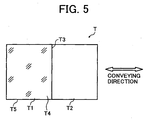
- Fig. 5 is a plan view of the recording medium used in the first embodiment.
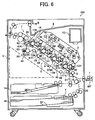
- Fig. 6 is a sectional view of an overall structure of the image forming apparatus according to the first embodiment.
- an image forming apparatus 100 includes four image forming units (image forming means) 1Y, 1M, 1C, and 1K that form images of respective colors of yellow (Y), magenta (M), cyan (C), and black (K).
- the image forming units 1Y, 1M, 1C, and 1K include photosensitive drums 11Y, 11M, 11C, and 11K serving as image bearing members, developing units 10Y, 10M, 10C, and 10K, and photosensitive units 2Y, 2M, 2C, and 2K, respectively.
- the photosensitive units include charging units and cleaning unit, respectively.
- An optical writing unit 3 including a light source, a polygon mirror, an f- ⁇ lens, and a reflection mirror is arranged above the image forming units 1Y, 1M, 1C, and 1K.
- the optical writing unit 3 irradiates a laser beam on the surfaces of the respective sensitive drums 11Y, 11M, 11C, and 11K while scanning the surfaces with the laser beam.
- a transfer unit 6 serving as a belt driving device is arranged below the image forming units 1Y, 1M, 1C, and 1K.
- the transfer unit 6 has a transfer conveyor belt 60 that conveys a recording medium T to pass transfer sections of the respective image forming units 1Y, 1M, 1C, and 1K.
- a cleaning device 85 including a brush roller and a cleaning blade is arranged to be in contact with the outer peripheral surface of the transfer conveyor belt 60. Foreign matters such as a toner adhering on the transfer conveyor belt 60 are removed by the cleaning device 85.
- the transfer conveyor belt 60 is driven to convey the recording medium T in an A direction in the figure by conveyor-belt driving rollers 61, 62, 63, and 66, a conveyor-belt armored roller 64, and a conveyor-belt tension roller 65 while being pulled by a spring 69 at a fixed tension set in advance.
- a belt opposed roller 80 is arranged in a position opposed to the conveyor belt driving roller 61 in a section where the recording medium T starts to be conveyed by the transfer conveyor belt 60.
- a fixing unit 7 of a belt fixing system, a sheet discharge tray 8, and a toner supply container TC are provided above the transfer unit 6.
- a waste toner bottle, a duplex/reversal unit, a power supply unit, and the like are provided in a space S indicated by an alternate long and two short dashes line.
- a sheet feeding unit (a sheet feeding device) 20 are provided in a lower part of the image forming apparatus 100.
- the sheet feeding unit 20 includes sheet feeding cassettes 4a and 4b in which recording media T are placed and registration rollers 5 that align a leading edge position of the recording medium T with front positions of the image forming units 1Y, 1M, 1C, and 1K.
- a registration sensor 74 is provided on the upstream side of the registration rollers 5.
- a boundary sensor 73 is provided on the downstream side of the registration rollers 5.
- a manual feed tray MF for manually feeding sheets is provided on a side of the image forming apparatus 100.
- the recording medium T has a transparent section T1 in one half thereof and a non-transparent section T2 in the other half.
- a position substantially in the center in a conveying direction of the recording medium T is a boundary T3 between the transparent section T1 and the non-transparent section T2.
- the non-transparent section T2 is white.
- a front surface T4 of the transparent section T1 is an image formation surface.
- the front surface T4 is formed as a smooth surface to obtain a photographic highly glossy image. If a rear surface T5 of the transparent section T1 serving as a non-image formation surface is also formed as a smooth surface, a photographic image quality having higher glossiness is obtained.
- the registration sensor 74 is provided in an upstream position in the recording medium T conveying direction of the registration rollers 5.
- the registration rollers 5 are put on standby in a state in which the recording medium T is in contact with a nip section 5a of the registration rollers 5.
- the boundary sensor 73 that detects a boundary between the transparent section T1 and the non-transparent section T2 of the recording medium T is provided in a downstream position in the recording medium T conveying direction of the registration rollers 5.
- the boundary sensor 73 is a transmission photosensor.
- the boundary sensor 73 includes a light emitting unit 73a that emits light to a conveyance surface of the recording medium T and a light receiving unit 73b that is provided in a position opposed to the light emitting unit 73a and detects the light from the light emitting unit 73a.
- the recording medium T is conveyed to the nip section 5a of the registration rollers 5.
- the transparent section T1, the non-transparent section T2, and the boundary T3 between the transparent section T1 and the non-transparent section T2 are provided in the recording medium T1.
- the boundary sensor 73 is arranged on the downstream side of the registration rollers 5. When the recording medium T is further conveyed, as shown in Fig.
- the transparent section T1 of the recording medium T is placed between the light emitting unit 73a and the light receiving unit 73b hidden under the transparent section T1.
- the light receiving unit 73b is receiving the light from the light emitting unit 73a and transmitting a light reception signal to a control unit.
- the boundary T3 between the transparent section T1 and the non-transparent section T2 of the recording medium T reaches the position of the boundary sensor 73.
- the control unit senses the light reception signal and detects the boundary T3 between the transparent section T1 and the non-transparent section T2 of the recording medium T.
- the non-transparent section T2 of the recording medium T is located in the position of the boundary sensor 73. Then, as shown in Fig. 4 , in the boundary sensor 73, the non-transparent section T2 of the recording medium T is located between the light emitting unit 73a and the light receiving unit 73b hidden under the non-transparent section T2. Therefore, the light is blocked by the non-transparent section T2.
- the developing devices 10Y, 10M, 10C, and 10K adopt the same two-component development system. Only colors of toners used therein are different. Developers including toners and magnetic carriers are stored in the developing devices 10Y, 10M, 10C, and 10K.
- Each of the developing devices 10Y, 10M, 10C, and 10K includes a developing roller opposed to each of the photosensitive drums 11Y, 11M, 11C, and 11K (collectively, "photosensitive drum 11"), a screw that carries and agitates the developer, and a toner density sensor.
- the developing roller includes a rotatable sleeve on the outer side and a magnet fixed on the inner side.
- the toner is supplied from a toner supply device according to an output of the toner density sensor.
- a predetermined voltage is applied to a charging roller from a power supply.
- the charging roller charges the surface of the photosensitive drum 11 opposed to the charging roller.
- the optical writing unit 3 irradiates a laser beam based on image data on the surface of the photosensitive drum 11 charged at a predetermined potential to write an electrostatic latent image thereon.
- a toner is supplied to the electrostatic latent image on the surface of the photosensitive drum 11 by the developing roller arranged to be opposed to the photosensitive drum 11. As a result, a toner image is formed on the surface.
- the operation described above is applied to all the photosensitive units 2Y, 2M, 2C, and 2K in the same manner at predetermined timing. Toner images of predetermined colors are formed on the surfaces of the photosensitive drums 11Y, 11M, 11C, and 11K, respectively.
- the recording medium T is conveyed from the sheet feeding cassette 4a or 4b or the manual feed tray MF. When the recording medium T reaches the nip section 5a of the registration rollers 5, the recording medium T temporarily stops ( Figs. 1 and 2 ). The registration rollers 5 forwards the recording medium T at timing coinciding with image forming operations of the photosensitive units 2Y, 2M, 2C, and 2K.
- the boundary T3 between the transparent section T1 and the non-transparent section T2 of the recording medium T is detected by the boundary sensor 73.
- the transparent section T1 of the recording medium T is located between the light emitting unit 73a and the light receiving unit 73b
- the light receiving unit 73b is receiving light from the light emitting unit 73a ( Fig. 3 ).
- the non-transparent section T2 is located between the light emitting unit 73a and the light receiving unit 73b. Then, light from the light emitting unit 73a is blocked by the non-transparent section T2 ( Fig. 4 ).
- the control unit senses a light reception signal in the light receiving unit 73b and detects the boundary T3 between the transparent section T1 and the non-transparent section T2 of the recording medium T.
- the control unit performs an image forming operation with the signal received by the light receiving unit 73b as a writing trigger.
- the toner images on the respective photosensitive drums 11Y, 11M, 11C, and 11K are transferred onto the recording medium T, which has passed the registration rollers 5, one after another while the recording medium T is conveyed by the transfer conveyor belt 60.
- the transfer conveyor belt 60 transfers the toner images onto the recording medium T according to application of a voltage, which has a polarity opposite to that of the toners on the photosensitive drums 11Y, 11M, 11C, and 11K, from the power supply to primary transfer rollers 67Y, 67M, 67C, and 67K.
- the primary transfer rollers 67Y, 67M, 67C, and 67K are arranged to be opposed to the photosensitive drums 11Y, 11M, 11C, and 11K across the transfer conveyor belt 60.
- the recording medium T passes a position where the primary transfer roller 67K and the photosensitive drum 11K opposed to each other, the toner images of the four colors are superimposed one on top of another on the recording medium T. Subsequently, the recording medium T is conveyed to the fixing unit 7 and an image 9 is fixed by heat and pressure.
- the recording medium T is discharged to the sheet discharge tray 8 through a recording-medium conveyance path indicated by an arrow B in Fig. 6 .
- a branching pawl G is switched to change the recording-medium conveyance path to a direction of an arrow C and discharge the recording medium T to the outside of the image forming apparatus.
- the recording medium T discharged is folded along the boundary T3 to superimpose the transparent section T1 and the non-transparent section T2 one on top of the other. Consequently, it is possible to treat the image 9 as a photographic image.
- the boundary sensor 73 is provided in the position on the downstream side in the recording medium T conveying direction of the registration rollers 5.
- the boundary sensor 73 is provided in the position on the downstream side in the recording medium T conveying direction of the registration rollers 5.
- the non-transparent section T2 of the recording medium T is white, when the recording medium T is folded along the boundary T3 to superimpose the transparent section T1 and the non-transparent section T2 one on top of the other, it is possible to obtain the image 9 excellent in color reproducibility.
- Fig. 7A is a plan view of a state in which a horizontally reversed image is formed in a transparent section of a recording medium according to the second embodiment.
- Fig. 7B is a perspective view of the transparent section and a non-transparent section of the recording medium superimposed one on top of the other after image formation according to the second embodiment.
- Fig. 8A is a plan view of a state in which a vertically reversed image is formed in the transparent section of the recording medium according to the second embodiment.
- Fig. 8B is a perspective view of the transparent section and the non-transparent section superimposed one on top of the other according to the second embodiment.
- the image 9 obtained by horizontally reversing an original image is formed on the front surface T4 of the transparent section T1 of the recording medium T as shown in Figs. 7A and 7B or the image 9 obtained by vertically reversing the original image is formed on the front surface T4 as shown in Figs. 8A and 8B .
- the control unit subjects image data read by a reading device to reversal processing.
- the optical writing unit 3 writes the image data after the reversal processing on a photosensitive member as an electrostatic latent image.
- a reversed image is transferred onto the recording medium T to form an image in the transparent section T1 ( Figs. 7A and 8A ).
- the image 9 obtained by horizontally or vertically reversing the original image is formed on the front surface T4 of the transparent section T1 of the recording medium T as described above. Consequently, when the recording medium T is folded along the boundary T3 to superimpose the transparent section T1 and the non-transparent section T2 one on top of the other, it is possible to obtain a normal non-reversed image viewed from a non-image surface (the rear surface) T5 of the recording medium T.
- the recording medium T along the boundary T3 between the transparent section T1 and the non-transparent section T2 to superimpose the transparent section T1 and the non-transparent section T2 one on top of the other.
- sheet feeding work is easier compared with work for separately feeding a transparent recording medium and a non-transparent recording medium.
- a structure required for superimposing the transparent recording medium and the non-transparent recording medium one on top of the other is unnecessary.
- the transparent section T1 and the non-transparent section T2 may be bonded after being folded and superimposed one on top of the other.
- the image formation surface is covered with the transparent section T1
- the image formation surface is not directly exposed to the outside. This makes it possible to maintain a high-quality image.
- Figs. 9A and 9B are plan views of the recording medium T with areas of the transparent section T1 and the non-transparent section T2 not equally divided according to a third embodiment of the present invention.
- an area of the transparent section T1 of the recording medium T is set to be equal to or smaller than a half of an area of the entire recording medium T.
- an area of the transparent section T1 of the recording medium T is set to be equal to or larger than a half of the area of the entire recording medium T.
- the boundary T3 between the transparent section T1 and the non-transparent section T2 is formed in a direction (an arrow direction) orthogonal to the conveying direction of the recording medium T to allow the boundary sensor 73 to detect the boundary T3 between the transparent section T1 and the non-transparent section T2.
- the third embodiment it is possible to freely change an area of the transparent section T1 of the recording medium T. Moreover, it is possible to use the recording medium T for various applications by forming the transparent section T1 large or forming the non-transparent section T2 large. Therefore, convenience of use of the recording medium T is satisfactory.
- Figs. 10A and 10B are plan views of formation of a reversed image in a transparent section of a recording medium and formation of a void image of an original image in a non-transparent section of the recording medium according to a fourth embodiment of the present invention.
- the reversed image 9 is formed in the transparent section T1 of the recording medium T and an image 9a obtained by making an original image void is formed in the non-transparent section T2.
- Fig. 11 is a diagram of a recording medium including a non-transparent section provided in a position surrounding a transparent section, in which an image is formed, according to a fifth embodiment of the present invention.
- the non-transparent section T2 is provided in a position surrounding the transparent section T1 in which the image 9 is formed.
- a leading edge T8 and a trailing end T7 in the recording medium conveying direction of the transparent section T1 is detected using the boundary sensor 73.
- the transparent section T1 is provided in an arbitrary position in the recording medium T, it is possible to detect the leading edge T8 and the trailing end T7 in the recording medium T conveying direction, which form boundaries between the transparent section T1 and the non-transparent section T2, using the boundary sensor 73 (not shown in Fig. 11 ) and form the image 9 in a target position of the transparent section T1.
- Fig. 12 is a plan view of image formation in a non-transparent section of a recording medium according to a sixth embodiment of the present invention.
- the image 9 is formed in the non-transparent section T2 of the recording medium T.
- the sixth embodiment even when the image 9 is formed in the non-transparent section T2, it is possible to detect the boundary T3 between the transparent section T1 and the non-transparent section T2 using the boundary sensor 73 (not shown in Fig. 12 ) and form the image 9 in a target position of the non-transparent section T2.
- Fig. 13 is an enlarged sectional view of a main part of a sheet feeding device according to a seventh embodiment of the present invention.
- a photosensor that uses reflected light is provided as the boundary sensor 73 on the downstream side of conveyance of the recording medium T through the nip section 5a of the registration rollers 5.
- the seventh embodiment it is possible to, making use of a difference between reflectance of the transparent section T1 and reflectance of the non-transparent section T2, detect the boundary T3 between the transparent section T1 and the non-transparent section T2 using the reflected light photosensor. Since it is possible to use the reflected light photosensor, choices of a photosensor are widened. This makes it possible to design a highly-accurate and highly-efficient sheet feeding device.
- Embodiments of the present invention are not limited to the first to the seventh embodiments described above. Various modifications of the embodiments are possible without departing from the spirit of the present invention.
- the non-transparent section T2 of the recording medium T is white.
- the non-transparent section T2 is not limited to white.
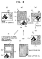
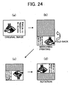
- Fig. 14 is a schematic diagram for explaining a procedure for creating a glossy image from a color original image including characters and illustrations according to an eighth embodiment of the present invention.
- a New Year's card with a glossy image is created.
- An original image 20M including characters and an illustration is indicated by (a) shown in Fig. 14 .
- An original image may be an image shown in an original or data stored in storing means such as a hard disk.
- a recording image (a toner image) 20m is formed on a recording medium 21, which is a sheet-like medium, using an image forming apparatus described later.
- the recording medium 21 includes a transparent section 21a and a non-transparent section 21b that can be folded back.
- an area of the transparent section 21a is smaller than an area of the non-transparent section 21b.
- a portion where the recording image 20m is formed is a surface on a side of the transparent section 21a that overlaps the non-transparent section 21b (functioning as an overlapping medium) when the transparent section 21a is folded back.
- an image formation surface of the transparent section 21a is backed by the non-transparent section 21b.
- a form of an image in the transparent section 21a is a mirror image obtained by reversing the front and the back of the original image 20M.
- the mirror image itself is formed in the transparent section 21a.
- a color, a pattern, and the like of the non-transparent section 21b on the same surface as the recording image 20m affect a background of a finished image when an adhesive described later is transparent.
- the non-transparent section 21b is designed as appropriate taking that point into account.
- the transparent section 21a is folded back along a boundary O-O between the transparent section 21a and the non-transparent section 21b with the image formation surface, on which the recording image 20m is formed, set on the inner side thereof.
- an adhesive is applied to an area overlapping the transparent section 21a (or the image formation surface) on the upper surface of the non-transparent section 21b in advance.
- the adhesive layer forms a background of a finished image.
- the non-transparent section 21b forms a background of a finished image. If the non-transparent section 21b is reflected on a background of a finished image, it is advisable to make the adhesive layer transparent. If a background of a finished image is set regardless of a color, a pattern, and the like of the non-transparent section 21b, the adhesive layer only has to be made non-transparent. It is considered that, if the adhesive always has a general white color as a background color, it is possible to cope with various images in many cases.
- the non-transparent section 21b passes a fixing roller unit or is conveyed by a conveying roller in the image formation process together with the transparent section 21a.
- the adhesive is applied to the non-transparent section 21b and exposed from the beginning, the adhesive sticks to the conveying roller. This is unsuitable for conveyance in the image forming apparatus.
- the adhesive only has to be applied to the non-transparent section 21b when the non-transparent section 21b is superimposed on the transparent section 21a after the recording medium 21 passes through the image forming apparatus.
- a heat-resistance seal only has to be stuck to the surface of the adhesive to protect the adhesive when the non-transparent section 21b passes a heat fixing unit and peeled off when the non-transparent section 21b is superimposed on the transparent section 21a.
- the transparent section 21a is integrated with the non-transparent section 21b via the adhesive by folding back the transparent section 21a.
- the area of the transparent section 21a is smaller than that of the non-transparent section 21b, as indicated by (c) shown in Fig. 14 , an overlapping section 21c that overlaps the transparent section 21a folded back and a blank section 21d are formed in the non-transparent section 21b.
- the non-transparent section 21b also serves as an overlapping medium.
- the overlapping section 21c it is possible to see an image that is the same as an original image (an image that is not a mirror image) through the transparent section 21a.
- Fig. 15 is a diagram of a state of creation of a transparent section and a non-transparent section of a recording medium equally divided according to the eighth embodiment.
- the boundary O-O between the transparent section 21a and the non-transparent section 21b is in a position for equally dividing the transparent section 21a and the non-transparent section 21b rather than the position for normally dividing the transparent section 21a and the non-transparent section 21b indicated by (b) shown in Fig. 14 .
- the recording medium 21 serves as an image recording medium, on which only an image is formed without a blank for handwriting information.
- an arbitrary folding-back section located in a boundary between the transparent section 21a and the non-transparent section 21b is folded back to integrate the transparent section 21a and the non-transparent section 21b via the adhesive. This makes it possible to easily obtain a highly glossy photograph image. It is also possible to easily realize creation of a blank section for handwriting a message or the like.
- a ninth embodiment of the present invention is explained.
- the ninth embodiment is the same as the eighth embodiment up to the process for forming the recording image 20m based on the original image 20M in the transparent section 21a of the recording medium 21 as indicated by (b) shown in Fig. 14 .
- a sheet-like overlapping medium 22 having the same size as the recording medium 21 is prepared as indicated by (e) shown in Fig. 14 .
- One side 22a of the overlapping medium 22 is a surface to be the back of an image recording medium finally manufactured.
- Other side 22b is a surface that could be a background of the recording image 20m.
- a white or transparent adhesive layer is formed on the other side 22b or the image formation surface of the recording medium 21.
- the overlapping medium 22 indicated by (e) shown in Fig. 14 is superimposed on the recording medium 21 such that the other side 22b is opposed to the recording image 20m indicated by (b) shown in Fig. 14 . Consequently, the overlapping member 22 is integrated with the recording medium 21 via the adhesive layer. If this integrated sheet is turned over, as indicated by (f) shown in Fig. 14 , an image recording medium having a glossy image is manufactured as in the eighth embodiment. In other words, in an overlapping section 22c, it is possible to see a correct image that is the same as the original image (an image that is not a mirror image) through the transparent section 21a.
- the rear surface of the non-transparent section 21b indicated by (b) shown in Fig. 14 is a blank section 22d indicated by (f) shown in Fig. 14 . It is possible to write necessary information in the blank section 22d later by handwriting or the like.
- the one side 22a of the overlapping medium 22 having the same size as the recording medium 21 is a surface to be the back of an image recording medium finally manufactured.
- the overlapping medium 22 is integrated with the recording medium 21 via the adhesive without folding back the image recording medium. This makes it possible to easily obtain a highly glossy photograph image.
- FIG. 16 A cross section of the image recording medium manufactured as described above is shown in Fig. 16 .
- the transparent section 21a and the non-transparent section 21b (the overlapping medium 22) are integrated via the adhesive layer.
- the recording image 20m is covered with the transparent section 21a.
- a storage life of the image is satisfactory. Since the surface of the transparent section 21a has glossiness, it is possible to look at the image as a photographic glossy image.
- Fig. 16 is a diagram of a state of observation through the transparent section 21a of the image recording medium according to the first to the ninth embodiments.
- a portion where the transparent section 21a is folded back is set as the boundary O-O between the transparent section 21a and the non-transparent section 21b in the recording medium 21. Consequently, as shown in Fig. 16 , it is possible to display an image in the transparent section 21a as a glossy image satisfactorily.
- a surface layer 25 is formed on the non-transparent section 21b and superimposed on the transparent section 21a with the recording image 20m formed on the transparent section 21a.
- Figs. 17A to 17C are diagrams of glossy image formation performed by folding back a recording medium provided with a linear concave section according to the eighth embodiment.
- concave lines 23 and 24 of a V shape in section are formed on both sides in the thickness direction (the vertical direction in the figure) in the boundary O-O to be opposed to each other.
- a concave line may be formed only on one side in the thickness direction in the boundary O-O.
- the non-transparent section 21b and the surface layer 25 are formed on the left side of the boundary O-O in the figure.
- the transparent section 21a is formed on the right side.
- a recording medium having a transparent section at least in a part thereof as shown in Fig 18 is used as a transfer sheet T.
- An image corresponding to an original image is written on the photosensitive drum 11 by light from the optical writing unit 3, developed with a color toner, and transferred onto the transparent section of the recording medium.
- the recording medium is discharged to the sheet discharge tray 8.
- the writing of the image by the optical writing unit 3 is performed to form an image reversed from the original image in the transparent section 21a of the recording medium 21. It is possible to input original image data from an external apparatus connected to the image forming apparatus. Alternatively, it is possible to use image information read by a not-shown scanner incidental to the image forming apparatus.
- Fig. 18 is a schematic diagram for explaining various examples of a recording medium including a transparent section and a non-transparent section at different ratios according to a tenth embodiment of the present invention.
- the transparent section 21a is smaller than the non-transparent section 21b.
- the transparent section 21a is larger than the non-transparent section 21b.
- the transparent section 21a and the non-transparent section 21b have the same size.
- the entire recording medium 21 indicated by (d) shown in Fig. 18 is the transparent section 21a.
- a conveying direction of the recording medium 21 may be an x direction or a y direction.
- a condition that these recording media having transparent sections at least in a part thereof are conveyed through the image forming apparatus is set.
- a method of setting the condition there are, for example, a method in which a user instructs the image forming apparatus to convey the recording media in a setting of sheet feeding means (the sheet feeding cassette 4a) in advance and a method in which the user registers a transparent area (the transparent section 21a) of a specific size in a control unit of the image forming apparatus in advance.
- the image forming apparatus After a transparent section is decided, when it is judged that an image is formed at least in the transparent section decided, the image forming apparatus automatically forms an image reversely. As a result, a reversed image is formed at least in the transparent section 21a on the recording medium after passing the fixing unit 7.
- the tenth embodiment it is possible to automatically process a series of operations for enlarging or reducing a size of an image to be outputted to a proper size according to an area decided as transparent by the image forming apparatus and applying reversal operation to the image.
- a difference between the manual work (the conventional technology) and the automatic work (the tenth embodiment) is schematically described below with general image forming means such as a copying machine or a printer as an example.
- step P-5 When it is judged at step P-1 that photographic print is selected, the program proceeds to step P-5.
- the program selects an image that should be printed and instructs the image forming apparatus to print the image.
- step P-6 the program checks whether recording media having transparent sections at least in a part thereof are set in a sheet feeding cassette or the like. When the recording media are not set, at step P-7, the program displays an error message. When the recording media are set, the program proceeds to step P-8.
- the program enlarges or reduces a size of an image to be formed in the transparent section 21a to adjust the size to a size of the transparent section.
- step P-9 the program processes image data to form a reversed image in the transparent section 21a.
- step P-10 the program adjusts an image writing position to place the image in the transparent section 21a. Subsequently, the program proceeds to step P-3.
- step P-4 the program executes printing of an image at a resolution and in a position conforming to the print instruction.
- an image obtained by reversing an original image is formed in the transparent section of the recording medium by the program of the control unit.
- a highly glossy photograph image obtained by superimposing the transparent section and the non-transparent section one on top of the other via an adhesive layer is automatically outputted from the image forming apparatus.
- Fig. 20 is an overall diagram of an image forming apparatus in which a center folding device is arranged according to an eleventh embodiment of the present invention.
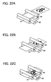
- Figs. 21A and 21B are schematic diagrams of a recording medium used as a transfer sheet in the eleventh embodiment.
- one half of the recording medium 21 shown in Fig. 21A is the non-transparent section 21b indicated by a shaded portion and the other half is the transparent section 21a indicated by a white portion.
- a part of the recording medium 21 may be the transparent section 21a in a white portion.
- a color of the white portion is not limited to white as long as the portion is non-transparent.
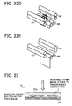
- Fig. 22 is a schematic perspective view for explaining details of processing in the center folding device according to the eleventh embodiment. Formation and fixing of an image in the transparent section 21a of the recording medium 21 are explained with reference to Fig. 20 and Figs. 22A to 22E . In this case, an image obtained by mirror-reversing an original image ((a) and (d) shown in Fig. 24 ) is printed in the transparent section 21a. In the eleventh embodiment, image formation on an image recording medium is performed according to operations that are the same as those performed by the image forming apparatus according to the first embodiment. Therefore, the same operations are performed until the recording medium 21 passes the fixing unit 7.
- the recording medium 21 is conveyed to a post-processing device (in this case, a center folding device E) from the image forming apparatus 100.
- the branching pawl G is arranged in an appropriate portion behind the fixing device. By switching the branching pawl G, the recording medium 21 is discharged to the sheet discharge tray 8 through a conveyance path B or discharged to the post-processing device E (in a C direction).
- a usual post-processing device to place sheets forming a printed material including a plurality of pages one on top of another in order, the sheets are reversed before entering the post-processing device.
- the eleventh embodiment by providing a not-shown branching device in a portion for the reversal, it is possible to send sheets to the post-processing device without reversing the sheets. In other words, it is possible to realize a way of folding opposite to a way of using a usual center folding device simply by providing the branching device.
- the center folding device is generally used to place a plurality of output sheets one on top of another, staple the center of the sheets, and fold the sheets. For a photographic image having a satisfactory storage fife according to the eleventh embodiment, a folding operation is carried out every time one photographic image is obtained. Thus, a reversing operation is unnecessary.
- the center folding device E includes roller pairs 86, 87, and 88.
- the recording medium 21 shown in Fig. 21A which is conveyed to the post-processing device (in this case, the center folding device E) from the image forming apparatus 100 after passing the fixing unit 7, is conveyed to the roller pair 87 through the roller pair 86 ( Figs. 22A and 22B ).
- the leading edge of the recording medium 21 conveyed to the roller pair 87 through the roller pair 86 is temporarily conveyed in an H direction in Fig. 20 .
- the roller pair 87 is reversely rotated to cause the recording medium 21 to sag to the roller pair 88 ( Fig. 22D ).
- the sagging recording medium 21 is nipped by the roller pair 88 to superimpose the non-transparent section 21b and the transparent section 21a of the recording medium 21 one on top of the other. Subsequently, the recording medium 21 is discharged in a J direction in Fig. 20 .
- Fig. 23 is a schematic sectional view of a state in which an image is formed on the recording medium according to the eleventh embodiment.
- Fig. 24 is a schematic diagram for explaining mirroring printing of an image according to the eleventh embodiment.
- Fig. 25 is a schematic sectional view of a usual printed image for comparison with a printed image according to the eleventh embodiment.
- the image formed as described above is outputted in a form of a toner layer present between the transparent section 21a and the non-transparent section 21b of the recording medium 21 as shown in Fig. 23 .
- the image is printed by mirroring in a procedure shown in Fig. 24 on the assumption that the image is bent.
- the toner image surface is seen from the rear side via the transparent section 21a as shown in Fig. 23 .
- a normal printed image in Fig. 25 lacks smoothness because an uneven toner surface is directly seen.
- the toner image formed by the image forming apparatus according to the eleventh embodiment is seen via the transparent section 21a, since the toner surface without unevenness is present in a line-of-sight direction, the toner image looks like a smooth image.
- the toner image looks like a photographic image because of the planarity of the toner image and the reflected light of the transparent section 21a.
- Figs. 26A and 26B are schematic diagrams of image surface layout at the time of center folding processing according to the eleventh embodiment.
- an image formation surface is usually laid out to place a first surface on the outer side with respect to the center fold.
- the first surface is placed on the inner side.
- the image surface is placed on a transparent section side of the recording medium.
- the center folding device is additionally arranged in the position behind the position where a recording medium passes the fixing unit of the conventional image forming apparatus to automatically apply the center folding processing to the recording medium on which an image is formed. This makes it possible to obtain a highly glossy photographic image.
- a twelfth embodiment of the present invention is explained.
- the structure of the center folding device added as the post-processing device of the image forming apparatus is changed. Therefore, in the twelfth embodiment, image formation on an image recording medium is performed according to operations that are the same as those performed by the image forming apparatus according to the first embodiment. A center folding operation after image formation is explained bellow.
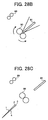
- Fig. 27 is a schematic diagram of a surface of a recording medium before starting the center folding operation in electrophotographic post processing according to the twelfth embodiment.
- Figs. 28A to 28C are schematic diagrams of a flow of the center folding operation in the electrophotographic post-processing according to the twelfth embodiment.
- the recording medium 21 is reversed and discharged with a first surface and a fourth surface placed on the outer side and a second surface and a third surface placed on the inner side.
- the recording medium 21 is conveyed to a roller pair 90 and a center folding plate 91, which serve as a center-folding processing unit, by a roller pair 89 ( Fig. 28A ).
- the center of the recording medium 21 is pushed from the outside by the center folding plate 91 ( Fig. 28B ) and passed through the roller pair 90. This makes it possible to fold one or a plurality of media.
- an image surface is laid out as shown in Fig. 26B .
- Fig. 29 is a schematic diagram of states before and after the center folding processing at the time when a transparent section of a recording medium is downstream in a conveying direction according to the twelfth embodiment.
- Fig. 30 is a schematic diagram of states before and after the center folding processing at the time when the transparent section of the recording medium is upstream in the conveying direction according to the twelfth embodiment.
- Figs. 29 and 30 unlike the general usage in Fig. 25 and Figs. 26A and 26B , an image is formed on the inner side of the fold.
- the surface of the recording medium 21 having the image is the transparent section 21a, when the image is seen from the rear surface of the recording medium, the image is a photographic image having uniform glossiness. Since the image surface is not directly touched, a storage life of the image is satisfactory. Moreover, since a surface opposed to the image surface is non-transparent white, a color of the image is clear. Therefore, it is possible to obtain a more preferable image.
- the heat-sensitive adhesive contains a solid plasticizer and thermoplastic resin emulsion as essential components and is obtained by mixing a tackifier or the like to these components.
- a heat-sensitive adhesive material is obtained by coating a mixture of these components over a support member.
- An adhesive layer surface of the heat-sensitive adhesive material does not show adhesiveness at all at the room temperature.
- the adhesiveness is developed when the heat-sensitive adhesive material is heated by a heat source. The adhesiveness is maintained for a while even after the heat source is removed (an adhesive state is semi-permanently maintained when the heat-sensitive adhesive material is stuck). It is considered that, first, the solid plasticizer is melted by heating and, then, the thermoplastic resin and the tackifier are melted, whereby the adhesiveness is developed.
- the heat-sensitive adhesive material of this type unlike the general adhesive material, releasing paper is not used.
- the heat-sensitive adhesive material is advantageous in terms of resource saving and environmental problems.
- the heat-sensitive adhesive material can be bonded to a member, to which the heat-sensitive adhesive material is bonded, by heating after being brought into contact with the member. Thus, it is possible to prevent a mistake in bonding the heat-sensitive adhesive material.
- the inventor has found that low-temperature adhesion is further facilitated by using, as a compound used for the solid plasticizer, at least one kind of compounds having, in particular, a benzoate group, a benzophenone group, a phenylenediamine group, and a benzothiazole group.
- the compound 1 having the benzoate group, the compound 2 having the benzophenone group, the compound 5 having the phenylenediamine group, and the compound 7 having the benzothiazole group have high compatibility with the thermoplastic resin and the tackifier.
- these compounds show high adhesiveness under the low-temperature environment.
- thermoplastic resin emulsion forming the heat-sensitive adhesive layer examples include resin such as a (meta)acrylic ester copolymer, a styrene-isoprene copolymer, a styrene-acrylic ester copolymer, a styrene-butadiene copolymer, an acrylonitrile-butadiene copolymer, an ethylene-vinyl acetate copolymer, a vinyl acetate-acrylic ester copolymer, an ethylene-chloroethylene copolymer, an ethylene-acrylic ester copolymer, a vinyl acetate-ethylene-chloroethylene copolymer, a vinyl acetate-ethylene-acrylic ester copolymer, a vinyl acetate-ethylene-styrene copolymer, polybut
- a tackifier to the heat-sensitive adhesive layer to improve adhesion.
- the tackifier include terpene resin, aliphatic petroleum resin, aromatic petroleum resin, coumarone-indene resin, styrene resin, phenolic resin, terpene phenol resin, and colophonium derivative resin.
- the tackifier is mixed at a ratio equal to or lower than 2.0 parts per million and preferably at a ratio in a range of 0.2 to 1.5 parts per million to 1.0 parts per million of the thermoplastic resin. When the tackifier exceeding 2.0 parts per million is mixed, blocking tends to occur.
- an anti-blocking agent When an anti-blocking agent is added in the heat-sensitive adhesive layer, blocking in the high-temperature environment is further prevented.
- the anti-blocking agent include a wax and an inorganic filler. Examples of the anti-blocking agent are listed below. However, the anti-blocking agent is not limited to the examples.
- waxes such as animal and vegetable waxes and a synthetic wax, higher fatty acid, higher fatty acid amide other than N-hydroxymethyl stearic amide and stearic amide, higher fatty acid anilide, acetylide of aromatic amine, a paraffin wax, a haze wax, a carnauba wax, shellac, a montan wax, paraffin oxide, a polyethylene wax, and polyethylene oxide.
- Examples of the higher fatty acid include stearic acid and behenic acid.
- Examples of the higher fatty acid amide include stearic amide, oleic amide, N-methyl stearic amide, erucamide, methylol behenic amide, methylol stearic amide, methylene bisstearic amide, and ethylene bisstearic amide.
- Examples of the higher fatty acid anilide include stearic anilide and linoleate anilide.
- Examples of the acetylide of aromatic amine include acetotoluidide.
- Examples of a heat fusion material other than waxes include a leuco dye and a developer generally used for a thermal recording material.
- the heat fusion materials including the wax desirably have as high a melting point as possible to prevent the heat fusion materials from affecting adhesion.
- the inorganic filler examples include carbonates, oxides, hydroxides, sulfates, and the like of aluminum, zinc, calcium, magnesium, barium, titanium, and the like and an inorganic pigment containing clays such as natural silica, zeolite, kaolin, and calcined kaolin. These inorganic fillers desirably have as low oil absorption as possible to prevent the inorganic fillers from affecting adhesion.
- anti-blocking agents are mixed at a ratio equal to or lower than 1.5 parts per million and preferably at a ratio in a range of 0.6 to 1.0 parts per million to 1.0 parts per million of the thermoplastic resin. When the anti-blocking agent exceeding 1.5 parts per million is mixed, adhesion tends to fall.
- an aqueous polymeric binder for example, polyvinyl alcohol, polyvinyl acetate, oxidized starch, etherified starch, a cellulose derivative such as carboxymethyl cellulose or hydroxyethyl cellulose, casein, gelatin, or alginic acid soda to the heat-sensitive adhesive layer.
- the aqueous polymeric binder is added at a ratio not spoiling original adhesion of a heat-sensitive adhesive sheet. Specifically, the aqueous polymeric binder is added at a ratio equal to or lower than 30% by weight and preferably equal to or lower than 10% by weight to a total solid content of the heat-sensitive adhesive layer. It is possible to add various additives such as a hardener, antiseptics, a dye, a developer, a pH moderator, and an anti-foaming agent to the heat-sensitive adhesive layer according to the present invention as required.
- a melting point of the solid plasticizer and the thermoplastic resin of the heat-sensitive adhesive layer is lower than a melting point of the toner. If the heating is performed at a temperature between the melting points, it is possible to bond heat-sensitive adhesive material to the member without melting the toner and disturbing the image.
- a thirteenth embodiment of the present invention is explained.
- the structure of the center folding device added as the post-processing device of the image forming apparatus is changed. Therefore, in the thirteenth embodiment, image formation on an image recording medium is performed according to operations that are the same as those performed by the image forming apparatus according to the first embodiment. An internal structure of the image recording medium and a center folding operation after image formation are explained bellow.
- Fig. 31 is a plan view of an example of an image recording medium according to the thirteenth embodiment.
- a recording medium section 110a having a transparent section 102 and a second medium section 101 including a heat-sensitive adhesive layer at least on one side thereof are arranged side by side on one sheet.
- the recording medium section 110a may have the transparent section 102 and a non-transparent section 103 in a part thereof or may have the transparent section 102 in one half and the non-transparent section 103 in the other half.
- the entire recording medium section 110a may be the transparent section 102. Since the second medium section 101 is non-transparent in this way, it is possible to easily recognize a color.
- Fig. 32 is a diagram of a procedure of image formation on the recording medium according to the thirteenth embodiment.
- An image is formed in the transparent section 102 of the recording medium section 110a.
- the second medium section 101 having a heat-sensitive adhesive layer formed thereon is folded and superimposed on an image formation surface 104 of the recording medium section 110a and integrated with the image formation surface 104. Consequently, a photographic image is obtained (see Fig. 32 ). Therefore, the image formation surface 104 of the recording medium section 110a and a heat-sensitive adhesive layer surface 101a of the second medium section 101 are on the same side.
- the second medium section 101 forms a background color, if a full-color photograph image is outputted, the second medium 10 is usually white. However, if a monotone image is outputted, it is not particularly necessary to limit a color of the second medium section 101 to white. A user may select the color of the second medium section 101 as the user likes.
- an image is formed on the recording medium by horizontally or vertically reversing an original image.
- the recording medium section 110a having the transparent section 102 at least in a part thereof at least the surface of the image formation surface 104 of the transparent section 102 is smooth.
- the heat-sensitive adhesive layer formed on the second medium section 101 is described below.
- Fig. 33 is a diagram of a structure of the second medium of the recording medium according to the thirteenth embodiment.
- the heat-sensitive adhesive contains a solid plasticizer and thermoplastic resin emulsion as essential components and is obtained by mixing a tackifier or the like to these components.
- a heat-sensitive adhesive material is obtained by coating a mixture of a mixture of these components over a support member (see Fig. 33 ).
- An adhesive layer surface of the heat-sensitive adhesive material does not show adhesiveness at all at the room temperature. However, the adhesiveness is developed when the heat-sensitive adhesive material is heated by a heat source. The adhesiveness is maintained for a while even after the heat source is removed.
- the solid plasticizer is melted by heating and, then, the thermoplastic resin and the tackifier are melted, whereby the adhesiveness is developed. It is possible to semi-permanently maintain an adhesive state in a stuck state.
- the heat-sensitive adhesive material of this type unlike the general adhesive material, releasing paper is not used.
- the heat-sensitive adhesive material is advantageous in terms of resource saving and environmental problems.
- the heat-sensitive adhesive material can be bonded to a member, to which the heat-sensitive adhesive material is bonded, by heating after being brought into contact with the member. Thus, it is possible to prevent a mistake in bonding the heat-sensitive adhesive material.
- the inventor has found that low-temperature adhesion is further facilitated by using, as a compound used for the solid plasticizer, at least one kind of compounds having, in particular, a benzoate group, a benzophenone group, a phenylenediamine group, and a benzothiazole group.
- a compound used for the solid plasticizer at least one kind of compounds having, in particular, a benzoate group, a benzophenone group, a phenylenediamine group, and a benzothiazole group.
- Tables 1 and 2 there is a compound 1 as the compound having the benzoate group
- compounds 2, 3, and 4 as the compound having the benzophenone group
- compounds 5 and 6 as the compound having the phenylenediamine group
- there are compounds 7, 8, 9, 10, and 11 as the compound having the benzothiazole group the compounds used for the solid plasticizer are not limited to these compounds.
- the compound 1 having the benzoate group, the compound 2 having the benzophenone group, the compound 5 having the phenylenediamine group, and the compound 7 having the benzothiazole group have high compatibility with the thermoplastic resin and the tackifier.
- these compounds show high adhesiveness under the low-temperature environment.
- thermoplastic resin emulsion forming the heat-sensitive adhesive layer examples include resin such as a (meta)acrylic ester copolymer, a styrene-isoprene copolymer, a styrene-acrylic ester copolymer, a styrene-butadiene copolymer, an acrylonitrile-butadiene copolymer, an ethylene-vinyl acetate copolymer, a vinyl acetate-acrylic ester copolymer, an ethylene-chloroethylene copolymer, an ethylene-acrylic ester copolymer, a vinyl acetate-ethylene-chloroethylene copolymer, a vinyl acetate-ethylene-acrylic ester copolymer, a vinyl acetate-ethylene-styrene copolymer, polybut
- a tackifier to the heat-sensitive adhesive layer to improve adhesion.
- the tackifier include terpene resin, aliphatic petroleum resin, aromatic petroleum resin, coumarone-indene resin, styrene resin, phenolic resin, terpene phenol resin, and colophonium derivative resin.
- the tackifier is mixed at a ratio equal to or lower than 2.0 parts per million and preferably at a ratio in a range of 0.2 to 1.5 parts per million to 1.0 parts per million of the thermoplastic resin. When the tackifier exceeding 2.0 parts per million is mixed, blocking tends to occur.
- an anti-blocking agent When an anti-blocking agent is added in the heat-sensitive adhesive layer, blocking in the high-temperature environment is further prevented.
- the anti-blocking agent include a wax and an inorganic filler. Examples of the anti-blocking agent are listed below. However, the anti-blocking agent is not limited to the examples.
- waxes such as animal and vegetable waxes and a synthetic wax, higher fatty acid, higher fatty acid amide other than N-hydroxymethyl stearic amide and stearic amide, higher fatty acid anilide, acetylide of aromatic amine, a paraffin wax, a haze wax, a carnauba wax, shellac, a montan wax, paraffin oxide, a polyethylene wax, and polyethylene oxide.
- higher fatty acid include stearic acid and behenic acid.
- Examples of the higher fatty acid amide include stearic amide, oleic amide, N-methyl stearic amide, erucamide, methylol behenic amide, methylol stearic amide, methylene bisstearic amide, and ethylene bisstearic amide.
- Examples of the higher fatty acid anilide include stearic anilide and linoleate anilide.
- Examples of the acetylide of aromatic amine include acetotoluidide.
- Examples of a heat fusion material other than the waxes include a leuco dye and a developer generally used for a thermal recording material.
- the heat fusion materials including the wax desirably have as high a melting point as possible to prevent the heat fusion materials from affecting adhesion.
- the inorganic filler include carbonates, oxides, hydroxides, sulfates, and the like of aluminum, zinc, calcium, magnesium, barium, titanium, and the like and an inorganic pigment containing clays such as natural silica, zeolite, kaolin, and calcined kaolin. These inorganic fillers desirably have as low oil absorption as possible to prevent the inorganic fillers from affecting adhesion.
- anti-blocking agents are mixed at a ratio equal to or lower than 1.5 parts per million and preferably at a ratio in a range of 0.6 to 1.0 parts per million to 1.0 parts per million of the thermoplastic resin. When the anti-blocking agent exceeding 1.5 parts per million is mixed, adhesion tends to fall.
- an aqueous polymeric binder for example, polyvinyl alcohol, polyvinyl acetate, oxidized starch, etherified starch, a cellulose derivative such as carboxymethyl cellulose or hydroxyethyl cellulose, casein, gelatin, or alginic acid soda to the heat-sensitive adhesive layer.
- the aqueous polymeric binder is added at a ratio not spoiling original adhesion of a heat-sensitive adhesive sheet.
- the aqueous polymeric binder is added at a ratio equal to or lower than 30% by weight and preferably equal to or lower than 10% by weight to a total solid content of the heat-sensitive adhesive layer. It is possible to add various additives such as a hardener, antiseptics, a dye, a developer, a pH moderator, and an anti-foaming agent to the heat-sensitive adhesive layer according to the present invention as required.
- Fig. 34 is a sectional view of a structure around a heating device and a folding device according to the thirteenth embodiment.
- Fig. 35 is a diagram of an entire apparatus mounted with the heating device and the folding device according to the thirteenth embodiment.
- the heat-sensitive adhesive layer is formed in the second medium section 101.
- the heat-sensitive adhesive layer does not show adhesiveness at all at the room temperature.
- the recording medium section 110a is set as a leading section of conveyance of the image recording medium 110.
- the fixing device 92 When the area having the toner image placed thereon of the recording medium section 110a passes the fixing device 92, the conveyance is reversed. In this case, since the area moves back and forth through the fixing device 92, it goes without saying that a fixing temperature and the like have to be optimized in this mode.
- the conveyance-path switching pawl 122 is changed over to a position indicated by a dotted line in Fig.
- folding processing is executed by folding rollers 121, two pairs of conveying rollers 123, and a pawl 124.
- the second medium section 101 may also be moved through the fixing device 92.
- FIG. 36 is a schematic diagram for explaining a folding process of a center folding device according to the thirteenth embodiment.
- the recording medium section 110a and the second medium section 101 of the image recording medium 110 are supported by the conveying rollers 123, respectively ((b) shown in Fig. 36 ).
- the conveying rollers 123 convey the image recording medium 110 while the respective pairs rotating in opposite directions to bend the image recording medium 110 ((c) shown in Fig. 36 ).
- the image recording medium 110 is conveyed in a bent state.
- a concave line 105 is provided ( Fig. 37 ) or perforations are provided on a surface at least on one side of a target position for folding the image recording medium 110 along the boundary between the recording medium section 110a and the second medium section 101 of the image recording medium 110.
- Fig. 37 is a diagram of an image recording medium that has a concave line according to the thirteenth embodiment.
- the image recording medium 110 is led to the heating device to activate the heat-sensitive adhesive layer.
- the heating device may be provided separately from the folding device.
- the image forming apparatus has a simplest structure if the folding rollers 121 also serve as the heating device.
- a melting point of the solid plasticizer and the thermoplastic resin of the heat-sensitive adhesive layer is lower than a melting point of the toner. If the heating is performed at a temperature lower than the melting point of the toner and higher than the melting point of the solid plasticizer and the thermoplastic resin, it is possible to bond the surfaces without melting the toner and disturbing the image.
- the image forming apparatus also has a path for discharging the image recording medium 110 or conveying the image recording medium 110 to the next process unit without conveying the medium through the folding device and the heating device according to the switching by the conveyance-path switching pawl 122.
- the next processing unit there are a reversal unit for duplex printing, a staple, a center binding unit, a punching unit, a bookbinding unit.
- This shortcut path is a conveyance path at the time of usual printing in which the second medium is unnecessary and photographic print is not performed. This is a conveyance path necessary for universality of the image forming apparatus.
- the image forming apparatus also has the path for discharging the image recording medium 110 or conveying the image recording medium 110 to the next process unit without conveying the medium through the folding device and the heating device.
- the path for discharging the image recording medium 110 or conveying the image recording medium 110 to the next process unit without conveying the medium through the folding device and the heating device is possible to cope with not only conveyance of the recording medium, with which a photographic image quality can be obtained, according to the thirteenth embodiment but also conveyance of other image recording media.
- a fourteenth embodiment of the present invention is explained.
- a fixing device also serves as a heating device. Therefore, in the fourteenth embodiment, image formation on an image recording medium is performed according to operations that are the same as those performed by the image forming apparatus according to the first embodiment. An internal structure of the image recording medium and a center folding operation after image formation are explained bellow.
- Fig. 38 is a diagram of a main part serving as a folding device, a heating device, and a fixing device according to the fourteenth embodiment.
- an unfixed image is directly carried through the folding device and fixing of a toner image and bonding of a recording medium are simultaneously performed by the heating device.
- the image forming apparatus since the image forming apparatus has a simple structure, it is possible to reduce the number of components of the image forming apparatus. This leads to a reduction in cost. It is also possible to apply the image forming apparatus to a recording method in which fixing of an image is not required such as an ink-jet recording method.
- the image forming apparatus has a shortcut conveyance path for usual printing in which the second medium section 101 is unnecessary and photographic print is not performed.
- the conveyance path is explained with reference to Fig. 38 .
- the image recording medium 110 is conveyed by an image forming system including a latent image process, a development process, and a transfer process and, then, conveyed to the conveying rollers 123 and fixing rollers 128.
- an image is fixed on the image recording medium 110 that does not pass the folding device, after the image recording medium 110 passes the conveying rollers 123, normal fixing processing is executed in the fixing rollers 128.
- the conveyance-path switching pawl 127 is changed over and placed in the folding position and the fixing rollers 128 are reversely rotated.
- the image recording medium 110 is folded and led into folding rollers 126.
- the image recording medium 110 led into the folding rollers 126 is completely folded by the conveyance by the folding rollers 126 and discharged through a path indicated by a dotted line in Fig. 38 .
- the image forming apparatus also has the medium conveyance path for supplying the image recording medium 110 to the heating device without conveying the image recording medium 110 through the folding device.
- the recording medium section 110a having the transparent section 102 at least in a part thereof and the second medium section 101 including the heat-sensitive adhesive layer at least on one side thereof are arranged side by side on one sheet.
- the image recording medium 110 is folded to bond the image formation surface of the recording medium section 110a and the surface of the second medium section 101 on which the heat-sensitive adhesive layer is formed. Consequently, an integral medium is formed.
- the image forming apparatus includes the folding device that folds at least the image recording medium 110 and the heating device that heats the image recording medium 110 folded by the folding device.
- the image forming apparatus is excellent in a medium stock property, a medium setting property, and a medium conveyance property in the process of forming a photographic image having a satisfactory storage life.
- the image forming apparatus has a selecting unit that selects a medium conveyance path for an arbitrary medium. This makes it possible to switch a conveyance path for a medium that requires a photographic image quality and a medium that does not require the photographic image quality.
- the selecting unit selects a medium conveyance path according to a print mode. This makes it possible to associate the print mode and necessity of the photographic image quality.
Landscapes
- Engineering & Computer Science (AREA)
- Ceramic Engineering (AREA)
- Textile Engineering (AREA)
- Physics & Mathematics (AREA)
- General Physics & Mathematics (AREA)
- Mechanical Engineering (AREA)
- Control Or Security For Electrophotography (AREA)
- Controlling Sheets Or Webs (AREA)
- Registering Or Overturning Sheets (AREA)
Claims (3)
- Blattzuführungsvorrichtung, aufweisend:ein Paar von Lagegenauigkeits- bzw. Registerrollen bzw. -walzen (5), die eine vordere Kante von einem Aufzeichnungsmedium (T) ausrichten, das einen transparenten Abschnitt (T1) und einen nicht transparenten Abschnitt (T2) hat; undeinen Grenzsensor (73), der eine Grenze (T3) zwischen dem transparenten Abschnitt (T1) und dem nicht transparenten Abschnitt (T2) detektiert, dadurch gekennzeichnet, dassder Grenzsensor (73) auf einer stromabwärts gelegenen Seite von einer Förderrichtung des Aufzeichnungsmediums (T) durch die Lagegenauigkeits- bzw. Registerrollen bzw. -walzen bereitgestellt ist.
- Bilderzeugungsapparat, aufweisend:die Blattzuführungsvorrichtung gemäß Anspruch 1;eine Bilderzeugungseinheit (1Y, 1M, 1C, 1K), die konfiguriert ist, um ein Bild auf einem Aufzeichnungsmedium (T) zu erzeugen, undeine Nachbearbeitungsvorrichtung, die eine Falt- bzw. Falzbearbeitungseinheit hat, wobei die Falt- bzw. Falzbearbeitungseinheit konfiguriert ist, um das Aufzeichnungsmedium (T) entlang der Grenze (T3) zwischen dem transparenten Abschnitt (T1) und dem nicht transparenten Abschnitt (T2) zu falten bzw. zu falzen, um den transparenten Abschnitt (T1) auf den nicht transparenten Abschnitt (T2) zu überlagern.
- Bilderzeugungsapparat gemäß Anspruch 2, wobei die Bilderzeugungseinheit (1Y, 1M, 1C, 1K) konfiguriert ist, um das Bild zu erzeugen, das durch horizontales oder vertikales Reversieren bzw. Umkehren eines ursprünglichen bzw. Originalbildes auf dem transparenten Abschnitt (T1) erlangt wurde.
Applications Claiming Priority (4)
| Application Number | Priority Date | Filing Date | Title |
|---|---|---|---|
| JP2006008207A JP2007191229A (ja) | 2006-01-17 | 2006-01-17 | 給紙装置及び画像形成装置 |
| JP2006027582A JP4828952B2 (ja) | 2006-02-03 | 2006-02-03 | 画像記録媒体の製法 |
| JP2006156714A JP2007320300A (ja) | 2006-06-05 | 2006-06-05 | 画像記録媒体 |
| JP2006190133A JP4827637B2 (ja) | 2006-07-11 | 2006-07-11 | 画像形成装置 |
Publications (3)
| Publication Number | Publication Date |
|---|---|
| EP1813559A2 EP1813559A2 (de) | 2007-08-01 |
| EP1813559A3 EP1813559A3 (de) | 2007-10-24 |
| EP1813559B1 true EP1813559B1 (de) | 2012-12-19 |
Family
ID=38118861
Family Applications (1)
| Application Number | Title | Priority Date | Filing Date |
|---|---|---|---|
| EP07000108A Not-in-force EP1813559B1 (de) | 2006-01-17 | 2007-01-04 | Blattzuführvorrichtung |
Country Status (2)
| Country | Link |
|---|---|
| US (1) | US7817953B2 (de) |
| EP (1) | EP1813559B1 (de) |
Families Citing this family (18)
| Publication number | Priority date | Publication date | Assignee | Title |
|---|---|---|---|---|
| US7657218B2 (en) * | 2006-08-22 | 2010-02-02 | Ricoh Company Ltd. | Gloss providing sheet and image formation apparatus |
| JP2008064804A (ja) * | 2006-09-04 | 2008-03-21 | Ricoh Co Ltd | 画像形成装置 |
| JP2008107660A (ja) * | 2006-10-26 | 2008-05-08 | Ricoh Co Ltd | 情報記録媒体 |
| JP2008134347A (ja) * | 2006-11-27 | 2008-06-12 | Ricoh Co Ltd | 画像形成装置 |
| US8023877B2 (en) * | 2006-12-25 | 2011-09-20 | Ricoh Company Limited | Image forming apparatus capable of forming glossy color image |
| JP5027602B2 (ja) * | 2007-06-26 | 2012-09-19 | 株式会社リコー | シート材切断装置及び画像形成装置 |
| KR20100030053A (ko) * | 2008-09-09 | 2010-03-18 | 삼성전자주식회사 | 후처리장치를 구비한 화상형성장치 및 화상형성장치의 후처리방법 |
| JP5321965B2 (ja) * | 2008-09-11 | 2013-10-23 | 株式会社リコー | 画像形成装置 |
| JP5424123B2 (ja) * | 2010-03-16 | 2014-02-26 | 株式会社リコー | 画像形成装置 |
| JP5545101B2 (ja) * | 2010-03-17 | 2014-07-09 | 株式会社リコー | 画像形成装置 |
| US9272496B2 (en) * | 2011-08-15 | 2016-03-01 | Thomas Finley Look | Secure devices for personal or article identification, such as driver'S licenses and vehicle license plates, and methods of producing such improved devices |
| JP6019916B2 (ja) | 2011-09-14 | 2016-11-02 | 株式会社リコー | 表示処理装置、画像形成システム、表示処理方法およびプログラム |
| JP6083413B2 (ja) * | 2014-05-26 | 2017-02-22 | コニカミノルタ株式会社 | 画像形成装置および画像形成方法 |
| JP6090234B2 (ja) | 2014-05-26 | 2017-03-08 | コニカミノルタ株式会社 | 画像形成装置および画像形成方法 |
| JP7109742B2 (ja) | 2018-10-30 | 2022-08-01 | 株式会社リコー | 画像記録媒体、画像記録媒体の製造方法、及び、画像形成装置 |
| JP7365579B2 (ja) | 2019-11-22 | 2023-10-20 | 株式会社リコー | シート収納装置及び画像形成装置 |
| US20220035296A1 (en) * | 2020-07-31 | 2022-02-03 | Canon Kabushiki Kaisha | Image forming apparatus |
| JP2023006021A (ja) * | 2021-06-30 | 2023-01-18 | キヤノン株式会社 | シート接着装置 |
Family Cites Families (43)
| Publication number | Priority date | Publication date | Assignee | Title |
|---|---|---|---|---|
| US3317038A (en) * | 1965-03-15 | 1967-05-02 | Pallam Dev Corp | Container structure |
| US4063641A (en) * | 1975-03-05 | 1977-12-20 | Philip Morris Industrial Incorporated | Two-side legible packaging film and package made therefrom |
| JPH02286Y2 (de) | 1984-12-12 | 1990-01-08 | ||
| US4721635A (en) * | 1985-11-08 | 1988-01-26 | Howtek, Inc. | Color printed record and method |
| JPS63113576A (ja) | 1986-10-31 | 1988-05-18 | Fuji Photo Film Co Ltd | 電子写真プリンタ− |
| JPH0347065U (de) | 1989-09-14 | 1991-04-30 | ||
| JPH0535151A (ja) | 1991-07-28 | 1993-02-12 | Ricoh Co Ltd | 画像形成方法及び画像形成装置 |
| US5223357A (en) * | 1992-02-03 | 1993-06-29 | Signs & Glassworks, Inc. | Promotional display signage and method of manufacture |
| US5303003A (en) * | 1992-02-06 | 1994-04-12 | Eastman Kodak Company | Color transparency having toner images transferred to both sides and method of making |
| US5337132A (en) * | 1993-07-21 | 1994-08-09 | Xerox Corporation | Apparatus for creating simulated color photographic prints using xerography |
| JPH0756409A (ja) | 1993-07-21 | 1995-03-03 | Xerox Corp | 擬似写真プリント作成方法 |
| JP2639618B2 (ja) | 1993-09-20 | 1997-08-13 | 株式会社 日本管理ラベル | 表示部材の作成方法 |
| KR100219601B1 (ko) * | 1996-05-15 | 1999-09-01 | 윤종용 | 인쇄면 판별영역을 갖는 ohp 및 승화형 열전사 프린터의 ohp 인쇄면 판별 방법 및 이에 적합한 장치 |
| JPH10123879A (ja) | 1996-10-18 | 1998-05-15 | Canon Inc | 出力装置および出力装置のデータ処理方法およびコンピュータが読み出し可能なプログラムを格納した記憶媒体 |
| JPH10278183A (ja) | 1997-02-05 | 1998-10-20 | Kayou Giken Kogyo Kk | 透明貼着体、その製造方法及び貼着物 |
| JP2000321842A (ja) | 1999-05-14 | 2000-11-24 | Canon Inc | 画像形成装置及び画像形成装置の制御方法 |
| JP4319740B2 (ja) | 1999-06-24 | 2009-08-26 | アルプス電気株式会社 | 印刷物および印刷方法ならびに印刷装置 |
| JP2001305894A (ja) | 2000-04-26 | 2001-11-02 | Ricoh Co Ltd | 画像形成方法 |
| JP2002019392A (ja) | 2000-07-07 | 2002-01-23 | Suematsu Ichiro | カラー画像裏面転写方法 |
| JP2002149009A (ja) * | 2000-11-08 | 2002-05-22 | Fujitsu Ltd | 透明被記録体、画像形成装置、及び、被記録体の種類を識別する装置 |
| JP2003029581A (ja) * | 2001-05-07 | 2003-01-31 | Ricoh Co Ltd | 画像形成装置 |
| JP3994688B2 (ja) | 2001-05-11 | 2007-10-24 | 富士ゼロックス株式会社 | カラー画像形成装置 |
| JP4284890B2 (ja) | 2001-06-13 | 2009-06-24 | 株式会社デンソー | 表示板 |
| JP2003015524A (ja) | 2001-06-28 | 2003-01-17 | Ricoh Co Ltd | 透明ラベル及びこれを用いる記録方法 |
| JP2003091110A (ja) | 2001-09-19 | 2003-03-28 | Canon Inc | 画像形成装置及び画像形成制御方法並びに記憶媒体 |
| JP3922688B2 (ja) | 2002-01-11 | 2007-05-30 | 株式会社リコー | 感熱性粘着材料 |
| JP2003208114A (ja) | 2002-01-17 | 2003-07-25 | Konan Komon:Kk | 光透過性の画像ユニット |
| JP3945281B2 (ja) | 2002-03-19 | 2007-07-18 | 富士ゼロックス株式会社 | 画像形成装置 |
| JP4226836B2 (ja) | 2002-04-02 | 2009-02-18 | 株式会社リコー | 可逆性多色表示媒体及びその多色表示方法 |
| JP3839342B2 (ja) | 2002-04-11 | 2006-11-01 | 株式会社リコー | 給紙装置及びそれを備えた画像形成装置 |
| JP2004037565A (ja) | 2002-06-28 | 2004-02-05 | Toppan Forms Co Ltd | アンダーコート層を有する透明印刷フィルム |
| JP2004045874A (ja) | 2002-07-12 | 2004-02-12 | Seiko Epson Corp | ラベルプリンタ |
| JP2004184553A (ja) | 2002-11-29 | 2004-07-02 | Koopakku International Kk | 印刷ラベル |
| JP2004191678A (ja) | 2002-12-11 | 2004-07-08 | Fuji Photo Film Co Ltd | 電子写真用受像シート及び画像形成方法 |
| JP2004302044A (ja) | 2003-03-31 | 2004-10-28 | Kojinsha:Kk | 画像表示プレート |
| JP4374214B2 (ja) | 2003-06-19 | 2009-12-02 | 小林クリエイト株式会社 | ラベル帳票 |
| JP2005250155A (ja) * | 2004-03-04 | 2005-09-15 | Fuji Xerox Co Ltd | 隠蔽情報所持体の作成装置、製造方法、画像形成装置、プリント制御装置、サービス方法およびプログラム |
| JP4330006B2 (ja) | 2004-09-13 | 2009-09-09 | 株式会社リコー | 感熱粘着層を有する感熱記録材料 |
| JP3646730B2 (ja) | 2004-09-27 | 2005-05-11 | 富士ゼロックス株式会社 | 画像形成装置 |
| JP4498122B2 (ja) * | 2004-12-20 | 2010-07-07 | キヤノン株式会社 | 画像形成方法 |
| US7620355B2 (en) * | 2005-08-01 | 2009-11-17 | Canon Kabushiki Kaisha | Glossiness processing apparatus and image forming apparatus |
| KR101021468B1 (ko) * | 2006-01-17 | 2011-03-15 | 가부시키가이샤 리코 | 화상 형성 장치 및 화상 형성 시스템 |
| US20080135160A1 (en) * | 2006-11-06 | 2008-06-12 | Yukiko Iwasaki | Sheet processing method and image forming apparatus |
-
2007
- 2007-01-04 US US11/649,204 patent/US7817953B2/en not_active Expired - Fee Related
- 2007-01-04 EP EP07000108A patent/EP1813559B1/de not_active Not-in-force
Also Published As
| Publication number | Publication date |
|---|---|
| US20070164505A1 (en) | 2007-07-19 |
| US7817953B2 (en) | 2010-10-19 |
| EP1813559A3 (de) | 2007-10-24 |
| EP1813559A2 (de) | 2007-08-01 |
Similar Documents
| Publication | Publication Date | Title |
|---|---|---|
| EP1813559B1 (de) | Blattzuführvorrichtung | |
| US7883089B2 (en) | Image forming apparatus | |
| US20080102399A1 (en) | Image sheet forming method and image sheet forming apparatus | |
| JP2005128046A (ja) | 画像形成装置、画像除去装置、画像形成除去システム | |
| EP1744225B1 (de) | Bilderzeugungssystem, Bilderzeugungsverfahren und Bilderzeugungsprogramm | |
| US7536149B2 (en) | Image forming apparatus | |
| CA2615113C (en) | Image forming apparatus, image forming system, paper feeding apparatus, image recording medium, and method of manufacturing image recording medium | |
| US8559043B2 (en) | Paper output device and image forming apparatus | |
| CN103293918A (zh) | 转印装置和图像形成设备 | |
| JP2009031652A (ja) | 画像形成装置 | |
| US20080135160A1 (en) | Sheet processing method and image forming apparatus | |
| JP2004005559A (ja) | 画像処理システム、および画像記録方法 | |
| CN100524062C (zh) | 图像记录介质、进纸器、以及图像形成装置 | |
| JP2008026407A (ja) | 画像記録媒体、画像記録媒体の製法および画像形成装置 | |
| US11713207B2 (en) | Recording material processing apparatus or image forming system each of which executes stapling process | |
| JP6124510B2 (ja) | 画像形成装置 | |
| JP2008137371A (ja) | シート処理方法及び画像形成装置 | |
| JP5137490B2 (ja) | 画像形成装置 | |
| JP4795315B2 (ja) | 画像形成除去システム | |
| JP4828952B2 (ja) | 画像記録媒体の製法 | |
| JP2002014500A (ja) | 画像形成装置 | |
| US11044372B2 (en) | Image forming apparatus | |
| JP2005035124A (ja) | Icメモリ入りプラスチックシートの作製装置 | |
| JP2007320300A (ja) | 画像記録媒体 | |
| CN101086638A (zh) | 成像设备 |
Legal Events
| Date | Code | Title | Description |
|---|---|---|---|
| PUAI | Public reference made under article 153(3) epc to a published international application that has entered the european phase |
Free format text: ORIGINAL CODE: 0009012 |
|
| AK | Designated contracting states |
Kind code of ref document: A2 Designated state(s): AT BE BG CH CY CZ DE DK EE ES FI FR GB GR HU IE IS IT LI LT LU LV MC NL PL PT RO SE SI SK TR |
|
| AX | Request for extension of the european patent |
Extension state: AL BA HR MK YU |
|
| PUAL | Search report despatched |
Free format text: ORIGINAL CODE: 0009013 |
|
| AK | Designated contracting states |
Kind code of ref document: A3 Designated state(s): AT BE BG CH CY CZ DE DK EE ES FI FR GB GR HU IE IS IT LI LT LU LV MC NL PL PT RO SE SI SK TR |
|
| AX | Request for extension of the european patent |
Extension state: AL BA HR MK YU |
|
| 17P | Request for examination filed |
Effective date: 20080317 |
|
| AKX | Designation fees paid |
Designated state(s): DE ES FR GB IT NL |
|
| GRAP | Despatch of communication of intention to grant a patent |
Free format text: ORIGINAL CODE: EPIDOSNIGR1 |
|
| GRAS | Grant fee paid |
Free format text: ORIGINAL CODE: EPIDOSNIGR3 |
|
| GRAA | (expected) grant |
Free format text: ORIGINAL CODE: 0009210 |
|
| AK | Designated contracting states |
Kind code of ref document: B1 Designated state(s): DE ES FR GB IT NL |
|
| REG | Reference to a national code |
Ref country code: GB Ref legal event code: FG4D |
|
| REG | Reference to a national code |
Ref country code: DE Ref legal event code: R096 Ref document number: 602007027408 Country of ref document: DE Effective date: 20130221 |
|
| PG25 | Lapsed in a contracting state [announced via postgrant information from national office to epo] |
Ref country code: ES Free format text: LAPSE BECAUSE OF FAILURE TO SUBMIT A TRANSLATION OF THE DESCRIPTION OR TO PAY THE FEE WITHIN THE PRESCRIBED TIME-LIMIT Effective date: 20130330 |
|
| REG | Reference to a national code |
Ref country code: NL Ref legal event code: VDEP Effective date: 20121219 |
|
| PG25 | Lapsed in a contracting state [announced via postgrant information from national office to epo] |
Ref country code: NL Free format text: LAPSE BECAUSE OF FAILURE TO SUBMIT A TRANSLATION OF THE DESCRIPTION OR TO PAY THE FEE WITHIN THE PRESCRIBED TIME-LIMIT Effective date: 20121219 |
|
| PLBE | No opposition filed within time limit |
Free format text: ORIGINAL CODE: 0009261 |
|
| STAA | Information on the status of an ep patent application or granted ep patent |
Free format text: STATUS: NO OPPOSITION FILED WITHIN TIME LIMIT |
|
| 26N | No opposition filed |
Effective date: 20130920 |
|
| PG25 | Lapsed in a contracting state [announced via postgrant information from national office to epo] |
Ref country code: IT Free format text: LAPSE BECAUSE OF FAILURE TO SUBMIT A TRANSLATION OF THE DESCRIPTION OR TO PAY THE FEE WITHIN THE PRESCRIBED TIME-LIMIT Effective date: 20121219 |
|
| REG | Reference to a national code |
Ref country code: DE Ref legal event code: R097 Ref document number: 602007027408 Country of ref document: DE Effective date: 20130920 |
|
| PGFP | Annual fee paid to national office [announced via postgrant information from national office to epo] |
Ref country code: DE Payment date: 20140122 Year of fee payment: 8 |
|
| PGFP | Annual fee paid to national office [announced via postgrant information from national office to epo] |
Ref country code: FR Payment date: 20140123 Year of fee payment: 8 |
|
| PGFP | Annual fee paid to national office [announced via postgrant information from national office to epo] |
Ref country code: GB Payment date: 20140121 Year of fee payment: 8 |
|
| REG | Reference to a national code |
Ref country code: DE Ref legal event code: R119 Ref document number: 602007027408 Country of ref document: DE |
|
| GBPC | Gb: european patent ceased through non-payment of renewal fee |
Effective date: 20150104 |
|
| PG25 | Lapsed in a contracting state [announced via postgrant information from national office to epo] |
Ref country code: DE Free format text: LAPSE BECAUSE OF NON-PAYMENT OF DUE FEES Effective date: 20150801 Ref country code: GB Free format text: LAPSE BECAUSE OF NON-PAYMENT OF DUE FEES Effective date: 20150104 |
|
| REG | Reference to a national code |
Ref country code: FR Ref legal event code: ST Effective date: 20150930 |
|
| PG25 | Lapsed in a contracting state [announced via postgrant information from national office to epo] |
Ref country code: FR Free format text: LAPSE BECAUSE OF NON-PAYMENT OF DUE FEES Effective date: 20150202 |