EP1707429A1 - Serien-hybridelektrofahrzeug - Google Patents
Serien-hybridelektrofahrzeug Download PDFInfo
- Publication number
- EP1707429A1 EP1707429A1 EP05703428A EP05703428A EP1707429A1 EP 1707429 A1 EP1707429 A1 EP 1707429A1 EP 05703428 A EP05703428 A EP 05703428A EP 05703428 A EP05703428 A EP 05703428A EP 1707429 A1 EP1707429 A1 EP 1707429A1
- Authority
- EP
- European Patent Office
- Prior art keywords
- revolution speed
- engine
- electric vehicle
- phase
- hybrid electric
- Prior art date
- Legal status (The legal status is an assumption and is not a legal conclusion. Google has not performed a legal analysis and makes no representation as to the accuracy of the status listed.)
- Withdrawn
Links
- 238000004804 winding Methods 0.000 claims abstract description 30
- 230000007935 neutral effect Effects 0.000 claims abstract description 22
- 230000007246 mechanism Effects 0.000 claims description 29
- 230000007423 decrease Effects 0.000 claims description 5
- 230000003247 decreasing effect Effects 0.000 claims description 4
- 230000004044 response Effects 0.000 claims description 3
- 238000000034 method Methods 0.000 abstract description 8
- 230000001965 increasing effect Effects 0.000 description 9
- 230000009467 reduction Effects 0.000 description 9
- 230000005540 biological transmission Effects 0.000 description 5
- 230000006872 improvement Effects 0.000 description 4
- 230000001939 inductive effect Effects 0.000 description 4
- 229910001219 R-phase Inorganic materials 0.000 description 3
- 230000018199 S phase Effects 0.000 description 3
- 230000008901 benefit Effects 0.000 description 3
- XEEYBQQBJWHFJM-UHFFFAOYSA-N Iron Chemical group [Fe] XEEYBQQBJWHFJM-UHFFFAOYSA-N 0.000 description 2
- 238000010586 diagram Methods 0.000 description 2
- 230000000694 effects Effects 0.000 description 2
- 229910000976 Electrical steel Inorganic materials 0.000 description 1
- 239000003990 capacitor Substances 0.000 description 1
- 238000006243 chemical reaction Methods 0.000 description 1
- 230000006866 deterioration Effects 0.000 description 1
- 238000009499 grossing Methods 0.000 description 1
- 230000016507 interphase Effects 0.000 description 1
- 239000000696 magnetic material Substances 0.000 description 1
Images


Classifications
-
- B—PERFORMING OPERATIONS; TRANSPORTING
- B60—VEHICLES IN GENERAL
- B60K—ARRANGEMENT OR MOUNTING OF PROPULSION UNITS OR OF TRANSMISSIONS IN VEHICLES; ARRANGEMENT OR MOUNTING OF PLURAL DIVERSE PRIME-MOVERS IN VEHICLES; AUXILIARY DRIVES FOR VEHICLES; INSTRUMENTATION OR DASHBOARDS FOR VEHICLES; ARRANGEMENTS IN CONNECTION WITH COOLING, AIR INTAKE, GAS EXHAUST OR FUEL SUPPLY OF PROPULSION UNITS IN VEHICLES
- B60K17/00—Arrangement or mounting of transmissions in vehicles
- B60K17/04—Arrangement or mounting of transmissions in vehicles characterised by arrangement, location, or kind of gearing
- B60K17/043—Transmission unit disposed in on near the vehicle wheel, or between the differential gear unit and the wheel
-
- B—PERFORMING OPERATIONS; TRANSPORTING
- B60—VEHICLES IN GENERAL
- B60K—ARRANGEMENT OR MOUNTING OF PROPULSION UNITS OR OF TRANSMISSIONS IN VEHICLES; ARRANGEMENT OR MOUNTING OF PLURAL DIVERSE PRIME-MOVERS IN VEHICLES; AUXILIARY DRIVES FOR VEHICLES; INSTRUMENTATION OR DASHBOARDS FOR VEHICLES; ARRANGEMENTS IN CONNECTION WITH COOLING, AIR INTAKE, GAS EXHAUST OR FUEL SUPPLY OF PROPULSION UNITS IN VEHICLES
- B60K6/00—Arrangement or mounting of plural diverse prime-movers for mutual or common propulsion, e.g. hybrid propulsion systems comprising electric motors and internal combustion engines ; Control systems therefor, i.e. systems controlling two or more prime movers, or controlling one of these prime movers and any of the transmission, drive or drive units Informative references: mechanical gearings with secondary electric drive F16H3/72; arrangements for handling mechanical energy structurally associated with the dynamo-electric machine H02K7/00; machines comprising structurally interrelated motor and generator parts H02K51/00; dynamo-electric machines not otherwise provided for in H02K see H02K99/00
- B60K6/20—Arrangement or mounting of plural diverse prime-movers for mutual or common propulsion, e.g. hybrid propulsion systems comprising electric motors and internal combustion engines ; Control systems therefor, i.e. systems controlling two or more prime movers, or controlling one of these prime movers and any of the transmission, drive or drive units Informative references: mechanical gearings with secondary electric drive F16H3/72; arrangements for handling mechanical energy structurally associated with the dynamo-electric machine H02K7/00; machines comprising structurally interrelated motor and generator parts H02K51/00; dynamo-electric machines not otherwise provided for in H02K see H02K99/00 the prime-movers consisting of electric motors and internal combustion engines, e.g. HEVs
- B60K6/22—Arrangement or mounting of plural diverse prime-movers for mutual or common propulsion, e.g. hybrid propulsion systems comprising electric motors and internal combustion engines ; Control systems therefor, i.e. systems controlling two or more prime movers, or controlling one of these prime movers and any of the transmission, drive or drive units Informative references: mechanical gearings with secondary electric drive F16H3/72; arrangements for handling mechanical energy structurally associated with the dynamo-electric machine H02K7/00; machines comprising structurally interrelated motor and generator parts H02K51/00; dynamo-electric machines not otherwise provided for in H02K see H02K99/00 the prime-movers consisting of electric motors and internal combustion engines, e.g. HEVs characterised by apparatus, components or means specially adapted for HEVs
- B60K6/26—Arrangement or mounting of plural diverse prime-movers for mutual or common propulsion, e.g. hybrid propulsion systems comprising electric motors and internal combustion engines ; Control systems therefor, i.e. systems controlling two or more prime movers, or controlling one of these prime movers and any of the transmission, drive or drive units Informative references: mechanical gearings with secondary electric drive F16H3/72; arrangements for handling mechanical energy structurally associated with the dynamo-electric machine H02K7/00; machines comprising structurally interrelated motor and generator parts H02K51/00; dynamo-electric machines not otherwise provided for in H02K see H02K99/00 the prime-movers consisting of electric motors and internal combustion engines, e.g. HEVs characterised by apparatus, components or means specially adapted for HEVs characterised by the motors or the generators
-
- B—PERFORMING OPERATIONS; TRANSPORTING
- B60—VEHICLES IN GENERAL
- B60K—ARRANGEMENT OR MOUNTING OF PROPULSION UNITS OR OF TRANSMISSIONS IN VEHICLES; ARRANGEMENT OR MOUNTING OF PLURAL DIVERSE PRIME-MOVERS IN VEHICLES; AUXILIARY DRIVES FOR VEHICLES; INSTRUMENTATION OR DASHBOARDS FOR VEHICLES; ARRANGEMENTS IN CONNECTION WITH COOLING, AIR INTAKE, GAS EXHAUST OR FUEL SUPPLY OF PROPULSION UNITS IN VEHICLES
- B60K6/00—Arrangement or mounting of plural diverse prime-movers for mutual or common propulsion, e.g. hybrid propulsion systems comprising electric motors and internal combustion engines ; Control systems therefor, i.e. systems controlling two or more prime movers, or controlling one of these prime movers and any of the transmission, drive or drive units Informative references: mechanical gearings with secondary electric drive F16H3/72; arrangements for handling mechanical energy structurally associated with the dynamo-electric machine H02K7/00; machines comprising structurally interrelated motor and generator parts H02K51/00; dynamo-electric machines not otherwise provided for in H02K see H02K99/00
- B60K6/20—Arrangement or mounting of plural diverse prime-movers for mutual or common propulsion, e.g. hybrid propulsion systems comprising electric motors and internal combustion engines ; Control systems therefor, i.e. systems controlling two or more prime movers, or controlling one of these prime movers and any of the transmission, drive or drive units Informative references: mechanical gearings with secondary electric drive F16H3/72; arrangements for handling mechanical energy structurally associated with the dynamo-electric machine H02K7/00; machines comprising structurally interrelated motor and generator parts H02K51/00; dynamo-electric machines not otherwise provided for in H02K see H02K99/00 the prime-movers consisting of electric motors and internal combustion engines, e.g. HEVs
- B60K6/42—Arrangement or mounting of plural diverse prime-movers for mutual or common propulsion, e.g. hybrid propulsion systems comprising electric motors and internal combustion engines ; Control systems therefor, i.e. systems controlling two or more prime movers, or controlling one of these prime movers and any of the transmission, drive or drive units Informative references: mechanical gearings with secondary electric drive F16H3/72; arrangements for handling mechanical energy structurally associated with the dynamo-electric machine H02K7/00; machines comprising structurally interrelated motor and generator parts H02K51/00; dynamo-electric machines not otherwise provided for in H02K see H02K99/00 the prime-movers consisting of electric motors and internal combustion engines, e.g. HEVs characterised by the architecture of the hybrid electric vehicle
- B60K6/46—Series type
-
- B—PERFORMING OPERATIONS; TRANSPORTING
- B60—VEHICLES IN GENERAL
- B60K—ARRANGEMENT OR MOUNTING OF PROPULSION UNITS OR OF TRANSMISSIONS IN VEHICLES; ARRANGEMENT OR MOUNTING OF PLURAL DIVERSE PRIME-MOVERS IN VEHICLES; AUXILIARY DRIVES FOR VEHICLES; INSTRUMENTATION OR DASHBOARDS FOR VEHICLES; ARRANGEMENTS IN CONNECTION WITH COOLING, AIR INTAKE, GAS EXHAUST OR FUEL SUPPLY OF PROPULSION UNITS IN VEHICLES
- B60K7/00—Disposition of motor in, or adjacent to, traction wheel
- B60K7/0007—Disposition of motor in, or adjacent to, traction wheel the motor being electric
-
- B—PERFORMING OPERATIONS; TRANSPORTING
- B60—VEHICLES IN GENERAL
- B60L—PROPULSION OF ELECTRICALLY-PROPELLED VEHICLES; SUPPLYING ELECTRIC POWER FOR AUXILIARY EQUIPMENT OF ELECTRICALLY-PROPELLED VEHICLES; ELECTRODYNAMIC BRAKE SYSTEMS FOR VEHICLES IN GENERAL; MAGNETIC SUSPENSION OR LEVITATION FOR VEHICLES; MONITORING OPERATING VARIABLES OF ELECTRICALLY-PROPELLED VEHICLES; ELECTRIC SAFETY DEVICES FOR ELECTRICALLY-PROPELLED VEHICLES
- B60L15/00—Methods, circuits, or devices for controlling the traction-motor speed of electrically-propelled vehicles
- B60L15/20—Methods, circuits, or devices for controlling the traction-motor speed of electrically-propelled vehicles for control of the vehicle or its driving motor to achieve a desired performance, e.g. speed, torque, programmed variation of speed
- B60L15/2045—Methods, circuits, or devices for controlling the traction-motor speed of electrically-propelled vehicles for control of the vehicle or its driving motor to achieve a desired performance, e.g. speed, torque, programmed variation of speed for optimising the use of energy
-
- B—PERFORMING OPERATIONS; TRANSPORTING
- B60—VEHICLES IN GENERAL
- B60L—PROPULSION OF ELECTRICALLY-PROPELLED VEHICLES; SUPPLYING ELECTRIC POWER FOR AUXILIARY EQUIPMENT OF ELECTRICALLY-PROPELLED VEHICLES; ELECTRODYNAMIC BRAKE SYSTEMS FOR VEHICLES IN GENERAL; MAGNETIC SUSPENSION OR LEVITATION FOR VEHICLES; MONITORING OPERATING VARIABLES OF ELECTRICALLY-PROPELLED VEHICLES; ELECTRIC SAFETY DEVICES FOR ELECTRICALLY-PROPELLED VEHICLES
- B60L50/00—Electric propulsion with power supplied within the vehicle
- B60L50/50—Electric propulsion with power supplied within the vehicle using propulsion power supplied by batteries or fuel cells
- B60L50/60—Electric propulsion with power supplied within the vehicle using propulsion power supplied by batteries or fuel cells using power supplied by batteries
- B60L50/61—Electric propulsion with power supplied within the vehicle using propulsion power supplied by batteries or fuel cells using power supplied by batteries by batteries charged by engine-driven generators, e.g. series hybrid electric vehicles
-
- H—ELECTRICITY
- H02—GENERATION; CONVERSION OR DISTRIBUTION OF ELECTRIC POWER
- H02K—DYNAMO-ELECTRIC MACHINES
- H02K19/00—Synchronous motors or generators
- H02K19/16—Synchronous generators
- H02K19/36—Structural association of synchronous generators with auxiliary electric devices influencing the characteristic of the generator or controlling the generator, e.g. with impedances or switches
-
- H—ELECTRICITY
- H02—GENERATION; CONVERSION OR DISTRIBUTION OF ELECTRIC POWER
- H02P—CONTROL OR REGULATION OF ELECTRIC MOTORS, ELECTRIC GENERATORS OR DYNAMO-ELECTRIC CONVERTERS; CONTROLLING TRANSFORMERS, REACTORS OR CHOKE COILS
- H02P25/00—Arrangements or methods for the control of AC motors characterised by the kind of AC motor or by structural details
- H02P25/16—Arrangements or methods for the control of AC motors characterised by the kind of AC motor or by structural details characterised by the circuit arrangement or by the kind of wiring
- H02P25/18—Arrangements or methods for the control of AC motors characterised by the kind of AC motor or by structural details characterised by the circuit arrangement or by the kind of wiring with arrangements for switching the windings, e.g. with mechanical switches or relays
- H02P25/184—Arrangements or methods for the control of AC motors characterised by the kind of AC motor or by structural details characterised by the circuit arrangement or by the kind of wiring with arrangements for switching the windings, e.g. with mechanical switches or relays wherein the motor speed is changed by switching from a delta to a star, e.g. wye, connection of its windings, or vice versa
-
- H—ELECTRICITY
- H02—GENERATION; CONVERSION OR DISTRIBUTION OF ELECTRIC POWER
- H02P—CONTROL OR REGULATION OF ELECTRIC MOTORS, ELECTRIC GENERATORS OR DYNAMO-ELECTRIC CONVERTERS; CONTROLLING TRANSFORMERS, REACTORS OR CHOKE COILS
- H02P9/00—Arrangements for controlling electric generators for the purpose of obtaining a desired output
- H02P9/02—Details of the control
-
- H—ELECTRICITY
- H02—GENERATION; CONVERSION OR DISTRIBUTION OF ELECTRIC POWER
- H02P—CONTROL OR REGULATION OF ELECTRIC MOTORS, ELECTRIC GENERATORS OR DYNAMO-ELECTRIC CONVERTERS; CONTROLLING TRANSFORMERS, REACTORS OR CHOKE COILS
- H02P9/00—Arrangements for controlling electric generators for the purpose of obtaining a desired output
- H02P9/04—Control effected upon non-electric prime mover and dependent upon electric output value of the generator
-
- H—ELECTRICITY
- H02—GENERATION; CONVERSION OR DISTRIBUTION OF ELECTRIC POWER
- H02P—CONTROL OR REGULATION OF ELECTRIC MOTORS, ELECTRIC GENERATORS OR DYNAMO-ELECTRIC CONVERTERS; CONTROLLING TRANSFORMERS, REACTORS OR CHOKE COILS
- H02P9/00—Arrangements for controlling electric generators for the purpose of obtaining a desired output
- H02P9/10—Control effected upon generator excitation circuit to reduce harmful effects of overloads or transients, e.g. sudden application of load, sudden removal of load, sudden change of load
- H02P9/102—Control effected upon generator excitation circuit to reduce harmful effects of overloads or transients, e.g. sudden application of load, sudden removal of load, sudden change of load for limiting effects of transients
-
- H—ELECTRICITY
- H02—GENERATION; CONVERSION OR DISTRIBUTION OF ELECTRIC POWER
- H02P—CONTROL OR REGULATION OF ELECTRIC MOTORS, ELECTRIC GENERATORS OR DYNAMO-ELECTRIC CONVERTERS; CONTROLLING TRANSFORMERS, REACTORS OR CHOKE COILS
- H02P9/00—Arrangements for controlling electric generators for the purpose of obtaining a desired output
- H02P9/10—Control effected upon generator excitation circuit to reduce harmful effects of overloads or transients, e.g. sudden application of load, sudden removal of load, sudden change of load
- H02P9/107—Control effected upon generator excitation circuit to reduce harmful effects of overloads or transients, e.g. sudden application of load, sudden removal of load, sudden change of load for limiting effects of overloads
-
- B—PERFORMING OPERATIONS; TRANSPORTING
- B60—VEHICLES IN GENERAL
- B60K—ARRANGEMENT OR MOUNTING OF PROPULSION UNITS OR OF TRANSMISSIONS IN VEHICLES; ARRANGEMENT OR MOUNTING OF PLURAL DIVERSE PRIME-MOVERS IN VEHICLES; AUXILIARY DRIVES FOR VEHICLES; INSTRUMENTATION OR DASHBOARDS FOR VEHICLES; ARRANGEMENTS IN CONNECTION WITH COOLING, AIR INTAKE, GAS EXHAUST OR FUEL SUPPLY OF PROPULSION UNITS IN VEHICLES
- B60K7/00—Disposition of motor in, or adjacent to, traction wheel
- B60K2007/0061—Disposition of motor in, or adjacent to, traction wheel the motor axle being parallel to the wheel axle
-
- B—PERFORMING OPERATIONS; TRANSPORTING
- B60—VEHICLES IN GENERAL
- B60L—PROPULSION OF ELECTRICALLY-PROPELLED VEHICLES; SUPPLYING ELECTRIC POWER FOR AUXILIARY EQUIPMENT OF ELECTRICALLY-PROPELLED VEHICLES; ELECTRODYNAMIC BRAKE SYSTEMS FOR VEHICLES IN GENERAL; MAGNETIC SUSPENSION OR LEVITATION FOR VEHICLES; MONITORING OPERATING VARIABLES OF ELECTRICALLY-PROPELLED VEHICLES; ELECTRIC SAFETY DEVICES FOR ELECTRICALLY-PROPELLED VEHICLES
- B60L2210/00—Converter types
- B60L2210/30—AC to DC converters
-
- B—PERFORMING OPERATIONS; TRANSPORTING
- B60—VEHICLES IN GENERAL
- B60L—PROPULSION OF ELECTRICALLY-PROPELLED VEHICLES; SUPPLYING ELECTRIC POWER FOR AUXILIARY EQUIPMENT OF ELECTRICALLY-PROPELLED VEHICLES; ELECTRODYNAMIC BRAKE SYSTEMS FOR VEHICLES IN GENERAL; MAGNETIC SUSPENSION OR LEVITATION FOR VEHICLES; MONITORING OPERATING VARIABLES OF ELECTRICALLY-PROPELLED VEHICLES; ELECTRIC SAFETY DEVICES FOR ELECTRICALLY-PROPELLED VEHICLES
- B60L2210/00—Converter types
- B60L2210/40—DC to AC converters
-
- B—PERFORMING OPERATIONS; TRANSPORTING
- B60—VEHICLES IN GENERAL
- B60L—PROPULSION OF ELECTRICALLY-PROPELLED VEHICLES; SUPPLYING ELECTRIC POWER FOR AUXILIARY EQUIPMENT OF ELECTRICALLY-PROPELLED VEHICLES; ELECTRODYNAMIC BRAKE SYSTEMS FOR VEHICLES IN GENERAL; MAGNETIC SUSPENSION OR LEVITATION FOR VEHICLES; MONITORING OPERATING VARIABLES OF ELECTRICALLY-PROPELLED VEHICLES; ELECTRIC SAFETY DEVICES FOR ELECTRICALLY-PROPELLED VEHICLES
- B60L2220/00—Electrical machine types; Structures or applications thereof
- B60L2220/40—Electrical machine applications
- B60L2220/46—Wheel motors, i.e. motor connected to only one wheel
-
- B—PERFORMING OPERATIONS; TRANSPORTING
- B60—VEHICLES IN GENERAL
- B60L—PROPULSION OF ELECTRICALLY-PROPELLED VEHICLES; SUPPLYING ELECTRIC POWER FOR AUXILIARY EQUIPMENT OF ELECTRICALLY-PROPELLED VEHICLES; ELECTRODYNAMIC BRAKE SYSTEMS FOR VEHICLES IN GENERAL; MAGNETIC SUSPENSION OR LEVITATION FOR VEHICLES; MONITORING OPERATING VARIABLES OF ELECTRICALLY-PROPELLED VEHICLES; ELECTRIC SAFETY DEVICES FOR ELECTRICALLY-PROPELLED VEHICLES
- B60L2220/00—Electrical machine types; Structures or applications thereof
- B60L2220/50—Structural details of electrical machines
- B60L2220/58—Structural details of electrical machines with more than three phases
-
- B—PERFORMING OPERATIONS; TRANSPORTING
- B60—VEHICLES IN GENERAL
- B60L—PROPULSION OF ELECTRICALLY-PROPELLED VEHICLES; SUPPLYING ELECTRIC POWER FOR AUXILIARY EQUIPMENT OF ELECTRICALLY-PROPELLED VEHICLES; ELECTRODYNAMIC BRAKE SYSTEMS FOR VEHICLES IN GENERAL; MAGNETIC SUSPENSION OR LEVITATION FOR VEHICLES; MONITORING OPERATING VARIABLES OF ELECTRICALLY-PROPELLED VEHICLES; ELECTRIC SAFETY DEVICES FOR ELECTRICALLY-PROPELLED VEHICLES
- B60L2240/00—Control parameters of input or output; Target parameters
- B60L2240/40—Drive Train control parameters
- B60L2240/42—Drive Train control parameters related to electric machines
- B60L2240/421—Speed
-
- B—PERFORMING OPERATIONS; TRANSPORTING
- B60—VEHICLES IN GENERAL
- B60L—PROPULSION OF ELECTRICALLY-PROPELLED VEHICLES; SUPPLYING ELECTRIC POWER FOR AUXILIARY EQUIPMENT OF ELECTRICALLY-PROPELLED VEHICLES; ELECTRODYNAMIC BRAKE SYSTEMS FOR VEHICLES IN GENERAL; MAGNETIC SUSPENSION OR LEVITATION FOR VEHICLES; MONITORING OPERATING VARIABLES OF ELECTRICALLY-PROPELLED VEHICLES; ELECTRIC SAFETY DEVICES FOR ELECTRICALLY-PROPELLED VEHICLES
- B60L2240/00—Control parameters of input or output; Target parameters
- B60L2240/40—Drive Train control parameters
- B60L2240/42—Drive Train control parameters related to electric machines
- B60L2240/423—Torque
-
- B—PERFORMING OPERATIONS; TRANSPORTING
- B60—VEHICLES IN GENERAL
- B60L—PROPULSION OF ELECTRICALLY-PROPELLED VEHICLES; SUPPLYING ELECTRIC POWER FOR AUXILIARY EQUIPMENT OF ELECTRICALLY-PROPELLED VEHICLES; ELECTRODYNAMIC BRAKE SYSTEMS FOR VEHICLES IN GENERAL; MAGNETIC SUSPENSION OR LEVITATION FOR VEHICLES; MONITORING OPERATING VARIABLES OF ELECTRICALLY-PROPELLED VEHICLES; ELECTRIC SAFETY DEVICES FOR ELECTRICALLY-PROPELLED VEHICLES
- B60L2240/00—Control parameters of input or output; Target parameters
- B60L2240/40—Drive Train control parameters
- B60L2240/44—Drive Train control parameters related to combustion engines
- B60L2240/441—Speed
-
- F—MECHANICAL ENGINEERING; LIGHTING; HEATING; WEAPONS; BLASTING
- F02—COMBUSTION ENGINES; HOT-GAS OR COMBUSTION-PRODUCT ENGINE PLANTS
- F02D—CONTROLLING COMBUSTION ENGINES
- F02D29/00—Controlling engines, such controlling being peculiar to the devices driven thereby, the devices being other than parts or accessories essential to engine operation, e.g. controlling of engines by signals external thereto
- F02D29/06—Controlling engines, such controlling being peculiar to the devices driven thereby, the devices being other than parts or accessories essential to engine operation, e.g. controlling of engines by signals external thereto peculiar to engines driving electric generators
-
- H—ELECTRICITY
- H02—GENERATION; CONVERSION OR DISTRIBUTION OF ELECTRIC POWER
- H02K—DYNAMO-ELECTRIC MACHINES
- H02K3/00—Details of windings
- H02K3/04—Windings characterised by the conductor shape, form or construction, e.g. with bar conductors
- H02K3/28—Layout of windings or of connections between windings
-
- Y—GENERAL TAGGING OF NEW TECHNOLOGICAL DEVELOPMENTS; GENERAL TAGGING OF CROSS-SECTIONAL TECHNOLOGIES SPANNING OVER SEVERAL SECTIONS OF THE IPC; TECHNICAL SUBJECTS COVERED BY FORMER USPC CROSS-REFERENCE ART COLLECTIONS [XRACs] AND DIGESTS
- Y02—TECHNOLOGIES OR APPLICATIONS FOR MITIGATION OR ADAPTATION AGAINST CLIMATE CHANGE
- Y02T—CLIMATE CHANGE MITIGATION TECHNOLOGIES RELATED TO TRANSPORTATION
- Y02T10/00—Road transport of goods or passengers
- Y02T10/60—Other road transportation technologies with climate change mitigation effect
- Y02T10/62—Hybrid vehicles
-
- Y—GENERAL TAGGING OF NEW TECHNOLOGICAL DEVELOPMENTS; GENERAL TAGGING OF CROSS-SECTIONAL TECHNOLOGIES SPANNING OVER SEVERAL SECTIONS OF THE IPC; TECHNICAL SUBJECTS COVERED BY FORMER USPC CROSS-REFERENCE ART COLLECTIONS [XRACs] AND DIGESTS
- Y02—TECHNOLOGIES OR APPLICATIONS FOR MITIGATION OR ADAPTATION AGAINST CLIMATE CHANGE
- Y02T—CLIMATE CHANGE MITIGATION TECHNOLOGIES RELATED TO TRANSPORTATION
- Y02T10/00—Road transport of goods or passengers
- Y02T10/60—Other road transportation technologies with climate change mitigation effect
- Y02T10/64—Electric machine technologies in electromobility
-
- Y—GENERAL TAGGING OF NEW TECHNOLOGICAL DEVELOPMENTS; GENERAL TAGGING OF CROSS-SECTIONAL TECHNOLOGIES SPANNING OVER SEVERAL SECTIONS OF THE IPC; TECHNICAL SUBJECTS COVERED BY FORMER USPC CROSS-REFERENCE ART COLLECTIONS [XRACs] AND DIGESTS
- Y02—TECHNOLOGIES OR APPLICATIONS FOR MITIGATION OR ADAPTATION AGAINST CLIMATE CHANGE
- Y02T—CLIMATE CHANGE MITIGATION TECHNOLOGIES RELATED TO TRANSPORTATION
- Y02T10/00—Road transport of goods or passengers
- Y02T10/60—Other road transportation technologies with climate change mitigation effect
- Y02T10/70—Energy storage systems for electromobility, e.g. batteries
-
- Y—GENERAL TAGGING OF NEW TECHNOLOGICAL DEVELOPMENTS; GENERAL TAGGING OF CROSS-SECTIONAL TECHNOLOGIES SPANNING OVER SEVERAL SECTIONS OF THE IPC; TECHNICAL SUBJECTS COVERED BY FORMER USPC CROSS-REFERENCE ART COLLECTIONS [XRACs] AND DIGESTS
- Y02—TECHNOLOGIES OR APPLICATIONS FOR MITIGATION OR ADAPTATION AGAINST CLIMATE CHANGE
- Y02T—CLIMATE CHANGE MITIGATION TECHNOLOGIES RELATED TO TRANSPORTATION
- Y02T10/00—Road transport of goods or passengers
- Y02T10/60—Other road transportation technologies with climate change mitigation effect
- Y02T10/7072—Electromobility specific charging systems or methods for batteries, ultracapacitors, supercapacitors or double-layer capacitors
-
- Y—GENERAL TAGGING OF NEW TECHNOLOGICAL DEVELOPMENTS; GENERAL TAGGING OF CROSS-SECTIONAL TECHNOLOGIES SPANNING OVER SEVERAL SECTIONS OF THE IPC; TECHNICAL SUBJECTS COVERED BY FORMER USPC CROSS-REFERENCE ART COLLECTIONS [XRACs] AND DIGESTS
- Y02—TECHNOLOGIES OR APPLICATIONS FOR MITIGATION OR ADAPTATION AGAINST CLIMATE CHANGE
- Y02T—CLIMATE CHANGE MITIGATION TECHNOLOGIES RELATED TO TRANSPORTATION
- Y02T10/00—Road transport of goods or passengers
- Y02T10/60—Other road transportation technologies with climate change mitigation effect
- Y02T10/72—Electric energy management in electromobility
Definitions
- the present invention is related to series hybrid electric vehicles, more particularly to a technique for improving energy efficiency of series hybrid electric vehicles.
- the series hybrid electric vehicle designates an electric vehicle configured to drive an electric generator by an engine, to supply electric power from the electric generator to a motor, and to drive wheels by the motor, as disclosed in Japanese Laid Open Patent Application JP-A-Heisei, 4-322105 , for example.
- the engine is dedicated to the electric generation, and the motive energy generated by the engine is not mechanically transmitted to the drive wheels, differently from a parallel hybrid electric vehicle.
- An advantage of the series hybrid electric vehicle lies in that the series hybrid electric vehicle ideally has high energy efficiency.
- the drive train mechanism in the parallel hybrid electric vehicle is complicated, since both of the engine and the motor are mechanically connected to the drive wheels. A complicated drive train mechanism may cause the loss of the energy.
- the drive train mechanism of the series hybrid electric vehicle can be simplified. The simplification of the drive train mechanism is effective for minimize the loss, and reducing the weight. Therefore, the series hybrid electric vehicle is excellent in the ideal energy efficiency.
- the series hybrid electric vehicle is required to ultimately improve the energy efficiency.
- the use of a mechanism that decreases the energy efficiency is not preferred, because it loses the advantage of the series hybrid electric vehicle.
- the first point in the improvement of the energy efficiency of the series hybrid electric vehicle is the loss in the electric generation system.
- the electric generation system is typically provided with an electric generator and an inverter for converting an alternating voltage generated by the electric generator into a direct voltage. It is difficult to avoid some loss, since the inverter is composed of switching transistors.
- the loss of an inverter is about 5 %. However, the loss of 5 % in the inverter is of importance in the series hybrid electric vehicle, where the energy efficiency is emphasized.
- the second point is improvement in the efficiency of the drive system.
- the losses of a transmission mechanism and a differential mechanism are also unignorable.
- the series hybrid electric vehicle is required to employ a drive system that avoids the losses in the transmission mechanism and the differential mechanism.
- An object of the present invention is generally to improve the energy efficiency of a series hybrid electric vehicle.
- an object of the present invention is to improve the energy efficiency of the electric generation system of a series hybrid electric vehicle.
- Another object of the present invention is to improve the energy efficiency of the drive system of a series hybrid electric vehicle.
- a series hybrid electric vehicle is composed of an engine; an n-phase generator driven by the engine; a rectifier generating a direct voltage from an n-phase alternating voltage received from the n-phase generator; a battery charged up with the generated direct voltage; a motor driving a drive wheel; an inverter driving the motor on the direct voltage received from the rectifier and/or a direct voltage received from the battery; and a switch.
- the rectifier is provided with n armature windings each having a first end connected to a common neutral point.
- the rectifier in provided with a negative terminal, a positive terminal having a potential higher than that on the negative terminal, and n rectifying arms.
- Each of the rectifying arms is composed of a first diode connected between the negative terminal and an intermediate node connected with a second end of the corresponding armature winding, and a second diode connected between the intermediate node and the positive terminal.
- the switch is connected between the neutral point and the negative terminal.
- the series hybrid electric vehicle thus structured uses the rectifier for converting the alternating voltage generated by the n-phase generator into the direct voltage, instead of an inverter.
- the use of the rectifier effectively improves the energy efficiency of the series hybrid electric vehicle, since the rectifier has higher conversion efficiency than that of the inverter.
- the use of the rectifier may cause an increase in the output voltage of the rectifier, that is, the direct voltage applied to the battery, because the rectifier does not have a function of controlling the output voltage.
- An excessive increase in the direct voltage applied to the battery may cause deterioration of the battery.
- the above-described series hybrid electric vehicle which has the switch between the neutral point and the negative terminal, can control the output voltage of the rectifier.
- the switch is responsive to the revolution speed of the engine for electrically connecting or disconnecting the neutral point and the negative terminal.
- the switch connects the neutral point and the negative terminal, the revolution speed of the engine exceeds a first revolution speed and reaches a second revolution speed higher than the first revolution speed.
- the switch disconnects the neutral point from the negative terminal. This avoids the excessive increase in the output voltage of the rectifier, when the revolution speed of the engine is increased.
- a star-delta switch mechanism may be used which switches the connections of the armature windings of the three-phase generator between the star connection and the delta connection, instead of the switch.
- the star-delta switch mechanism connects the armature windings in selected one of the star and delta connections in response to the engine revolution.
- the star-delta switch mechanism connects the armature windings in the delta connection, when the revolution speed of the engine exceeds a first revolution speed and reaches a second revolution speed higher than the first revolution speed.
- the star-delta switch mechanism connects the armature windings in the star connection. This avoids the excessive increase in the output voltage of the rectifier, when the revolution speed of the engine is increased.
- the above-described series hybrid electric vehicle preferably adopts a drive system which incorporates multiple motors that drives drive wheels, respectively.
- the drive system such designed eliminates the necessity of a transmission mechanism and a differential mechanism, and thereby improves the efficiency thereof.
- the motors are required to be small in the size, and large in the output torque.
- the motors are IPM motors structured as follows:
- the IPM motors are composed of a rotor coupled to the corresponding drive wheel, a stator having a plurality of slots circumferenced and spaced at constant intervals, and the rotor is composed of a rotor core and permanent magnets constituting field magnets.
- the rotor has a rotor side face facing the stator, and the permanent magnets have a pole face outward in the radial direction.
- the IPM motors thus constructed satisfies requirements of the reduced size and the large output torque, and allows the adoption of the above-described drive system in which the motors drive the drive wheels, respectively.
- the present invention improves the efficiency of the electric generation system and/or the drive system of the series hybrid electric vehicle, and thereby improves the energy efficiency of the series hybrid electric vehicle.
- a series hybrid electric vehicle 1 is provided with an engine 2, a five-phase generator 3, a five-phase diode rectifier 4, and a battery 5.
- the revolution speed of the engine 2 is controlled by a controller (not shown).
- the engine 2 is connected to the five-phase generator 3.
- the five-phase generator 3 is driven by the engine 2 to generate a five-phase alternating voltage, and supplies the generated five-phase alternating voltage to the five-phase diode rectifier 4.
- the five-phase diode rectifier 4 rectifies the five-phase alternating voltage, and generates a direct voltage.
- the battery 5 is charged by the direct voltage generated by the five-phase diode rectifier 4.
- the series hybrid electric vehicle 1 further includes drive inverters 6, motors 7, reduction gears 8, and drive wheels 9.
- the drive inverters 6 generate poly-phase electric power from the direct-current power supplied from the five-phase diode rectifier 4 and/or the battery 5.
- the motors 7 are driven by the generated poly-phase electric power, and generate motive energy. The generated motive energy is transmitted through the reduction gears 8 to the drive wheel 9.
- Fig. 2 is a schematic view illustrating the structure of the five-phase generator 3 and the five-phase diode rectifier 4.
- the five-phase generator 3 is provided with a rotor (not shown) connected to the engine 2, and a stator provided with five armature windings 11 1 to 11 5 . First ends of the armature windings 11 1 to 11 5 are connected to a neutral point 12.
- the five-phase diode rectifier 4 is a five-phase full-wave rectifying circuit having five rectifying arms 13 1 to 13 5 .
- the five rectifying arms 13 1 to 13 5 are connected in parallel between a positive terminal 15 and a negative terminal 16.
- a direct current output voltage V o is generated between the positive terminal 15 and the negative terminal 16, and the generated output voltage V o is supplied to the battery 5 and the drive inverters 6.
- a smoothing capacitor 14 is connected between the positive terminal 15 and the negative terminal 16.
- Each rectifying arm 13 i includes two series-connected diodes 17 i and 18 i .
- the cathode of the diode 17 i is connected to the positive terminal 15, and the anode thereof is connected to an intermediate node 19 i .
- the cathode of the diode 18 i is connected to the intermediate node 19 i , and the anode thereof is connected to the negative terminal 16.
- the intermediate node 19 i of each rectifying arm 13 i is connected to the second end (the end opposite to the neutral point 12) of the armature winding 11 i .
- a short-circuit switch 20 is provided between the neutral point 12 of the five-phase generator 3 and the negative terminal 16 of the five-phase diode rectifier 4. When the short-circuit switch 20 is turned on, the neutral point 12 is electrically short-circuited to the negative terminal 16.
- One feature of the series hybrid electric vehicle in this embodiment lies in the design which uses the five-phase diode rectifier 4, and thereby excludes an inverter composed of switching transistors.
- an inverter composed of switching transistors typically has a loss of 5 %.
- the loss of a rectifier is smaller than the loss of an inverter, and therefore the use of a rectifier effectively improves the efficiency of the electric generation system.
- the five-phase diode rectifier typically achieves an efficiency of 99 %.
- the five-phase diode rectifier 4 does not have a function of adjusting the output voltage V o by it self. This may cause a problem in charging the battery 5.
- the output voltage V o of the five-phase diode rectifier 4 is also increased. An excessive increase in the output voltage V o may cause the battery 5 to be excessively charged, which may deteriorate the battery 5.
- the foregoing short-circuit switch 20 is turned on, in response to the increase in the revolution speed of the engine 2.
- the short-circuit switch 20 is turned on, when the revolution speed of the engine 2 exceeds a predetermined first revolution speed n 1 , and electrically short-circuits the neutral point 12 and the negative terminal 16.
- Short-circuiting the neutral point 12 and the negative terminal 16 allows the five-phase diode rectifier 4 to be switched from the state in which the five-phase diode rectifier 4 operates as a five-phase full wave rectifying circuit to the state in which the five-phase diode rectifier 4 operates as a five-phase half wave rectifying circuit. This reduces the output voltage V o .
- the short-circuit switch 20 is turned on in the following procedure.
- the revolution speed of the engine 2 is low, the short-circuit switch 20 is turned off.
- the controller controlling the revolution speed of the engine 2 detects that the revolution speed of the engine 2 is about to exceed the first revolution speed n 1 , the revolution speed of the engine 2 is reduced to a third revolution speed n 3 by the controller.
- the output voltage of the five-phase generator 3 is reduced below the voltage of the battery 5. This results in that the supply of the electric power is terminated from the five-phase generator 3 to the battery 5 and the driving inverter 6. Consequently, the electric power is supplied from only the battery 5 to the driving inverter 6, and the motor 7 is driven by the electric power from the battery 5.
- the short-circuit switch 20 is turned on, and the revolution speed of the engine 2 is increased to exceed the first revolution speed n 1 up to the second revolution speed n 2 (>n 1 ), by the controller.
- the five-phase generator 3 again supplies the electric power to the battery 5 and the driving inverter 6. This procedure avoids the load on the engine 2 being varied abruptly.
- the revolution speed of the engine 2 is reduced from the second revolution speed n 2 and is about to reach the first revolution speed n 1 .
- the revolution speed of the engine 2 is reduced to a fourth revolution speed n 4 lower than the first revolution speed n 1 .
- the short-circuit switch 20 is turned off to electrically disconnect the neutral point 12 and the negative terminal 16.
- the disconnection of the neutral point 12 from the negative terminal 16 allows the five-phase diode rectifier 4 to return to the original state in which the five-phase diode rectifier 4 functions as the five-phase full wave rectifier.
- the revolution speed of the engine 2 is increased from the fourth revolution speed n 4 to the first revolution speed n 1 , by the controller.
- the short-circuit switch 20 is not turned off while the electric power is supplied to the battery 5 and the drive inverters 6, and this eliminates the need for the short-circuit switch 20 to be provided with a current shutdown function. This is preferable from the viewpoint of the miniaturization of the short-circuit switch 20. Also, this allows prolonging the lifetime of the short-circuit switch 20, since the short-circuit switch 20 does not shut down the electric power.
- the five-phase diode rectifier 4 is used to improve the energy efficiency, instead of a, inverter in the electric generation system in this embodiment.
- the problem that the five-phase diode rectifier 4 does not have the function of adjusting the output voltage V o is avoided by installing the short-circuit switch 20.
- an electric generator and a diode rectifier in which the number of the phases is different from the above-mentioned number for example, a three-phase electric generator and a three-phase diode rectifier may be used instead of the five-phase generator 4 and the five-phase diode rectifier 5. It should be noted, however, that the use of the five-phase generator 4 and the five-phase diode rectifier 5 is effective for the improvement of the energy efficiency.
- one driving inverter 6 and one set of reduction gears 8 are prepared for each drive wheel 9 in this embodiment. Revolution speeds of the motors 7 are determined so that the series hybrid electric vehicle 1 runs at a desired speed in a desired traveling direction.
- Such structure eliminates the need of a transmission mechanism and a differential mechanism, and is effective for the improvement of the energy efficiency.
- the motors 7 have a reduced size and a sufficiently large output. In order to attain the running performance requested for the vehicle, the motors 7 are required to have a sufficiently large output. However, the series hybrid electric vehicle 1 is allowed to incorporate only small motors 7, because the spaces prepared for the motors 7 is not large. The motors 7 are required to satisfy those conflicting requirements. In the structure of Fig. 7 that requires the plurality of motors 7, the miniaturization of the motor 7 is very important.
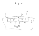
- the five-phase IPM motors shown in Fig. 3 are used as the motors 7.
- the five-phase IPM motors 7 are provided with a stator 31 and a rotor 32.
- the stator 31 is provided with armature teeth 33.
- the armature teeth 33 are arranged on the same circumference and spaced at constant intervals.
- a slot 34 is formed between the adjacent two armature teeth 33.
- the slots 34 are arranged on the same circumference at constant intervals. In this embodiment, the number n 2 of slots is 20.
- An armature coil 35 is wound around each of the armature teeth 33. In order to generate a rotating magnetic field in the stator 31, a five-phase armature current is fed to the armature coils 35.
- the rotor 32 is provided with a shaft 36 and a rotor core 37.
- the shaft 36 is rotatably supported by bearings (not shown).
- the shaft 36 is connected to the above-described reduction gears 8.
- the rotor core 37 is fixedly coupled to the shaft 36 and is rotated with the shaft 36.
- the rotor core 37 is made of magnetic material, such as silicon steel plates.
- Field magnets 38 are inserted into the rotor iron core 37.
- Each of the field magnets 38 constitutes one pole of the field magnet system of the rotor 32 and generates magnetic field lines in the radial direction of the rotor 32.
- the adjacent two field signets 38 generate the magnetic field lines in the opposite directions. That is, the polarities of the adjacent two field magnets 38 are opposite.
- the number of the field magnets 38 namely, the number n 1 of the pole of the field magnet system is 22.
- each of the field magnets 38 is composed of two permanent magnets 39 and 40 which are arranged in the circumferential direction of the rotor 32 and have the same polarity. That is, each pole of the field magnet system is composed of the two permanent magnets 39 and 40.
- the permanent magnets 39 and 40 have magnetic pole faces 39a and 40a facing outward in the radial direction of the rotor 32, and have magnetic pole faces 39b and 40b facing inward in the radius direction.
- the magnetic field lines generated by the permanent magnets 39 and 40 are emitted in the radius directions from the magnetic pole faces 39a, 39b, 40a and 40b.
- One set of the permanent magnets 39 and 40 within one field magnet 38 generates the magnetic field lines in the same directions, namely, has the same polarity. It should be noted that the number of the permanent magnets constituting the field magnet 38 of one pole is not limited to 2; the number of the permanent magnets may be one, or three or more.
- Portions 17a located outside in the radius directions of the permanent magnets 39 and 40 are prepared for the rotor iron core 37.
- the existence of the magnetic field lines inducing portions 37a is important for generating a reluctance torque, and achieving the weak field control.
- the volume of the magnetic field lines inducing portions 37a is selected so as to obtain a desirable reluctance torque and to achieve the weak magnetic field control.
- the embedding depth of the permanent magnets 39 and 40 from the rotor side face 32a (namely, the distance from a point on the magnetic pole faces 39a and 40a outward in the outward radial direction to the rotor side face 32a) is shallow in the IPM motors 7 shown in Fig. 3.
- the shallow embedding depth increases the ratio of the component of the magnet torque in the output torque outputted from the IPM motors 7.
- the magnet torque is the main component of the output torque of the IPM motors 7 shown in Fig. 3; the reluctance torque is the auxiliary component.
- the shallow embedding depth of the permanent magnets 39 and 40 is important for increasing the output torque per volume of the IPM motors 7.
- the shallow embedding depth of the permanent magnets 39 and 40 reduces the quadrature axis inductance.
- the reduction in the quadrature axis inductance may be considered to reduce the output torque of the IPM motor; however, this does not hold in the case when the embedding depth of the permanent magnets 39 and 40 is shallow.
- the shallow embedding depth of the permanent magnets 39 and 40 results in that the magnet torque component out of the output torques of the IPM motors 7 is larger than the reluctance torque component.
- the existence of the magnetic field lines inducing portions 37a is important for achieving the weak magnetic field control.
- a high output torque can be outputted due to the weak magnetic field control, even when the revolution speed of the rotor 32 is high.
- the use of the structure in which the embedding depth of the permanent magnets 39 and 40 is shallow achieves an increased output torque per volume over a wide revolution speed range.
- the IPM motors 7 having such characteristics are preferably used to drive the drive wheels 9 in the mechanism shown in Fig. 1.
- the series hybrid electric vehicle in this embodiment does not require a transmission mechanism nor a differential mechanism, through preparing one drive inverter 6, one motor 7, and one set of reduction gears 8 for each drive wheel 9. Therefore, the energy efficiency of the drive system driving the drive wheels 9 is improved.
- the use of such structure is accompanied by the requirements of the reduced size and the increased output on the motors 7, these requirements can be satisfied by using the IPM motor shown in Fig. 3 as the motor 7, in which the embedding depth of the permanent magnets is shallow.
- a three-phase electric generator 3' is used in place of the five-phase generator 3, and a three-phase diode rectifier 4' is used in place of the five-phase diode rectifier 4.
- the three-phase diode rectifier 4' has the same configuration as the five-phase diode rectifier 4, except for that the number of the phases is different (namely, the number of the rectifying arms is different).
- the proper adjustment of the output voltage V o outputted from the three-phase diode rectifier 4' is important for protecting the battery 5.
- a mechanism for adjusting the output voltage V o is separately required, since the three-phase diode rectifier 4' does not have the adjusting function for the output voltage V o , by itself.
- Prepared in this embodiment is a switching mechanism for switching the connections of the armature windings of the three-phase electric generator 3' between the star connection and the delta connection, instead of the short-circuit switch 20. This allows the output voltage V o outputted from the three-phase diode rectifier 4' to be adjusted.
- Fig. 6 schematically illustrates the structures of the three-phase electric generator 3' and the switching mechanism for switching the connections therein.
- the three-phase electric generator 3' has an R-phase terminal 21r, an S-phase terminal 21s, a T-phase terminal 21t, an X-terminal 22x, a Y-terminal 22y and a Z-terminal 22z .
- One armature winding out of the three armature windings (none of them is shown) in the three-phase electric generator 3' is provided between the R-phase terminal 21r and the X-terminal 22x, and another armature winding is provided between the S-phase terminal 21s and the Y-terminal 22y, and the remaining one armature winding is provided between the T-phase terminal 21t and the 2-terminal 22z.
- the R-phase terminal 21r, the S-phase terminal 21s and the T-phase terminal 21t are connected to a U-phase terminal 23u, a V-phase terminal 23v and a W-phase terminal 23w, respectively.
- the three-phase electric generator 3' supplies a three-phase alternating voltage through the U-phase terminal 23u, the V-phase terminal 23v and the W-phase terminal 23w to the three-phase diode rectifier 4'.
- the switching mechanism is composed of star switches 24 1 to 24 3 , and delta switches 25 1 to 25 3 .
- the star switches 24 1 , 24 2 , and 24 3 are disposed to connect a neutral point 26 to the X-terminal 22x, the Y-terminal 22y and the Z-terminal 22z, respectively.
- the delta switch 25 1 is connected between the Z-terminal 22z and the U-phase terminal 23u
- the delta switch 25 2 is connected between the X-terminal 22x and the V-phase terminal 23v
- the delta switch 253 is connected between the Y-terminal 22y and the W-phase terminal 23w.
- the three-phase alternating voltage outputted from the three-phase electric generator 3' is adjusted through the turn-on and turn-off of the star switches 24 1 to 24 3 and the delta switches 25 1 to 25 3 , and thereby the output voltage V o of the three-phase diode rectifier 4' is also adjusted. This avoids an excessive charging of the battery 5 due to the increase in the revolution speed of the engine 2.
- the operations of the star switches 24 1 to 24 3 and the delta switches 25 1 to 25 2 will be described below in detail.
- the switching from the star connection to the delta connection is carried out as follows.
- the revolution speed of the engine 2 is low, the armature windings of the three-phase electric generator 3' are star-connected. That is, the delta switches 251 to 25 3 are turned off, and the star switches 24 1 to 24 3 are turned on.
- the controller for controlling the revolution speed of the engine 2 detects that the revolution speed of the engine 2 is about to exceed the first revolution speed n 1 , the revolution speed of the engine 2 is reduced to a third revolution speed n 3 by the controller. As a result, the output voltage of the three-phase electric generator 3' is reduced below the voltage of the battery 5.
- the controller detects that the revolution speed of the engine 2 is reduced from the second revolution speed n 2 , and is about to reach the first revolution speed n 1 , on the other hand, the revolution speed of the engine 2 is reduced to a fourth revolution speed n 4 lower than the first revolution speed n 1 .
- the armature windings of the three-phase electric generator 3' are switched from the delta connection to the star connection. That is, the star switches 24 1 to 24 3 are turned on, and the delta switches 25 1 to 25 3 are turned off.
- the controller increases the revolution speed of the engine 2 from the fourth revolution speed n 4 to the first revolution speed n 1 . This procedure avoids the load on the engine 2 being varied abruptly.
- the star switches 24 1 to 24 3 and the delta switches 25 1 to 25 3 are not turned off, while the electric power is supplied to the battery 5 and the drive inverters 6. Therefore, these switches are not required to be provided with the current shutdown function. This is preferable from the viewpoint of the miniaturization of the switches. Additionally, it is possible to prolong the lifetime of the star switches 24 1 to 24 3 and the delta switches 25 1 to 25 3 , since these switches do not shut down the electric power.
- the three-phase diode rectifier 4' is used instead of an inverter, in the electric generation system in this embodiment, which improves the energy efficiency.
- the problem that the five-phase diode rectifier 4 ' does not have the adjusting function for the output voltage V o is avoided by the fact that the connections of the armature windings of the three-phase electric generator 3' are switchable between the star connection and the delta connection.
Landscapes
- Engineering & Computer Science (AREA)
- Power Engineering (AREA)
- Mechanical Engineering (AREA)
- Transportation (AREA)
- Combustion & Propulsion (AREA)
- Chemical & Material Sciences (AREA)
- Sustainable Energy (AREA)
- Life Sciences & Earth Sciences (AREA)
- Sustainable Development (AREA)
- Electric Propulsion And Braking For Vehicles (AREA)
- Combined Controls Of Internal Combustion Engines (AREA)
- Permanent Magnet Type Synchronous Machine (AREA)
- Hybrid Electric Vehicles (AREA)
- Control Of Vehicle Engines Or Engines For Specific Uses (AREA)
Applications Claiming Priority (2)
| Application Number | Priority Date | Filing Date | Title |
|---|---|---|---|
| JP2004006047A JP3993564B2 (ja) | 2004-01-13 | 2004-01-13 | シリーズハイブリッド電気自動車 |
| PCT/JP2005/000189 WO2005068244A1 (ja) | 2004-01-13 | 2005-01-11 | シリーズハイブリッド電気自動車 |
Publications (2)
| Publication Number | Publication Date |
|---|---|
| EP1707429A1 true EP1707429A1 (de) | 2006-10-04 |
| EP1707429A4 EP1707429A4 (de) | 2013-01-02 |
Family
ID=34792125
Family Applications (1)
| Application Number | Title | Priority Date | Filing Date |
|---|---|---|---|
| EP05703428A Withdrawn EP1707429A4 (de) | 2004-01-13 | 2005-01-11 | Serien-hybridelektrofahrzeug |
Country Status (4)
| Country | Link |
|---|---|
| US (1) | US7635039B2 (de) |
| EP (1) | EP1707429A4 (de) |
| JP (1) | JP3993564B2 (de) |
| WO (1) | WO2005068244A1 (de) |
Cited By (3)
| Publication number | Priority date | Publication date | Assignee | Title |
|---|---|---|---|---|
| EP1864843A3 (de) * | 2006-05-17 | 2009-11-04 | PIAGGIO & C. S.p.A. | Elektrisches angetriebenes Vierradfahrzeug |
| WO2012059368A3 (de) * | 2010-11-05 | 2012-12-20 | Lti Drives Gmbh | Notbetriebsfähige pitchmotor-antriebsschaltung |
| WO2013004409A1 (de) * | 2011-07-07 | 2013-01-10 | Schaeffler Technologies AG & Co. KG | Statorhalteplatte mit inverterbefestigungsfunktion |
Families Citing this family (36)
| Publication number | Priority date | Publication date | Assignee | Title |
|---|---|---|---|---|
| US7605493B1 (en) * | 2005-11-09 | 2009-10-20 | Joseph P. Boudreaux | Electrically powered vehicle engine |
| EP2008860B1 (de) * | 2007-06-25 | 2015-06-17 | Mazda Motor Corporation | Steuerung für ein Hybridfahrzeug |
| EP2008853B1 (de) | 2007-06-25 | 2010-09-15 | Mazda Motor Corporation | Hybridfahrzeug |
| DE102007031605A1 (de) * | 2007-07-06 | 2009-01-22 | Dr. Ing. H.C. F. Porsche Aktiengesellschaft | Hybridfahrzeug |
| JP2009148073A (ja) | 2007-12-14 | 2009-07-02 | Mazda Motor Corp | バッテリの充電方法および充電装置 |
| JP4906836B2 (ja) * | 2008-04-07 | 2012-03-28 | 三菱電機株式会社 | 電動機駆動装置および冷凍空気調和装置ならびに電動機駆動方法 |
| US20100065356A1 (en) * | 2008-09-15 | 2010-03-18 | Caterpillar Inc. | Electric powertrain for off-highway trucks |
| US20100163321A1 (en) * | 2008-12-30 | 2010-07-01 | Goff Sean K | Power converter module for a battery-operated vehicle |
| DE102009033531A1 (de) * | 2009-07-10 | 2011-01-20 | Dr. Ing. H.C. F. Porsche Aktiengesellschaft | Antriebsvorrichtung für ein Kraftfahrzeug mit einer elektrische Maschinen aufweisenden Portalachse |
| DE112010004022T5 (de) | 2009-10-13 | 2012-12-27 | Honda Motor Co., Ltd. | Hybridfahrzeug |
| JP5354818B2 (ja) | 2009-10-13 | 2013-11-27 | 本田技研工業株式会社 | ハイブリッド車両 |
| JP5348808B2 (ja) * | 2009-10-13 | 2013-11-20 | 本田技研工業株式会社 | ハイブリッド車両 |
| US20110232984A1 (en) * | 2010-02-13 | 2011-09-29 | Charles Richard Wurm | Independent axle drive |
| DE102010010438A1 (de) * | 2010-02-26 | 2011-09-01 | Dr. Ing. H.C. F. Porsche Aktiengesellschaft | Fahrwerk für ein Kraftfahrzeug mit einer elektrichen Achse |
| US8337352B2 (en) | 2010-06-22 | 2012-12-25 | Oshkosh Corporation | Electromechanical variable transmission |
| DE102010042050A1 (de) * | 2010-10-06 | 2012-04-12 | Robert Bosch Gmbh | Verfahren zum Betreiben einer elektrischen Maschine |
| DE102011002990B4 (de) * | 2011-01-21 | 2014-02-27 | Carl Zeiss Meditec Ag | Visualisieren von Gewebe in einem Operationsbereich |
| US8936120B2 (en) * | 2011-12-29 | 2015-01-20 | Kawasaki Jukogyo Kabushiki Kaisha | Utility vehicle having a front electric motor |
| JP5858309B2 (ja) * | 2012-11-28 | 2016-02-10 | 富士電機株式会社 | 電力変換システム及びその制御方法 |
| US9132736B1 (en) | 2013-03-14 | 2015-09-15 | Oshkosh Defense, Llc | Methods, systems, and vehicles with electromechanical variable transmission |
| US9656659B2 (en) | 2015-02-17 | 2017-05-23 | Oshkosh Corporation | Multi-mode electromechanical variable transmission |
| US9650032B2 (en) | 2015-02-17 | 2017-05-16 | Oshkosh Corporation | Multi-mode electromechanical variable transmission |
| US10421350B2 (en) | 2015-10-20 | 2019-09-24 | Oshkosh Corporation | Inline electromechanical variable transmission system |
| US12078231B2 (en) | 2015-02-17 | 2024-09-03 | Oshkosh Corporation | Inline electromechanical variable transmission system |
| US11701959B2 (en) | 2015-02-17 | 2023-07-18 | Oshkosh Corporation | Inline electromechanical variable transmission system |
| US10982736B2 (en) | 2015-02-17 | 2021-04-20 | Oshkosh Corporation | Multi-mode electromechanical variable transmission |
| US9651120B2 (en) | 2015-02-17 | 2017-05-16 | Oshkosh Corporation | Multi-mode electromechanical variable transmission |
| US10578195B2 (en) | 2015-02-17 | 2020-03-03 | Oshkosh Corporation | Inline electromechanical variable transmission system |
| US10584775B2 (en) | 2015-02-17 | 2020-03-10 | Oshkosh Corporation | Inline electromechanical variable transmission system |
| JP6461683B2 (ja) * | 2015-04-02 | 2019-01-30 | 株式会社クボタ | 電動作業車両 |
| KR102345445B1 (ko) * | 2015-07-07 | 2022-01-03 | 주식회사 만도 | 계자 전류 공급 장치 및 계자 전류 공급 방법 |
| US9764633B1 (en) | 2016-03-16 | 2017-09-19 | Caterpillar Inc. | Electric drivetrain system and method having a single speed ratio direct drive |
| US10723211B2 (en) * | 2016-09-07 | 2020-07-28 | Thunder Power New Energy Vehicle Development Company Limited | Integrated powertrain system |
| JP6916646B2 (ja) * | 2017-03-30 | 2021-08-11 | 本田技研工業株式会社 | エンジン発電機 |
| JP6825961B2 (ja) * | 2017-03-30 | 2021-02-03 | 本田技研工業株式会社 | エンジン発電機 |
| CN108859733B (zh) * | 2018-08-12 | 2024-06-28 | 姜春辉 | 一种电动汽车、轮毂电机及轮毂电机电子差速系统 |
Citations (5)
| Publication number | Priority date | Publication date | Assignee | Title |
|---|---|---|---|---|
| FR2089190A5 (de) * | 1970-04-03 | 1972-01-07 | Nippon Denso Co | |
| EP0251916A1 (de) * | 1986-07-04 | 1988-01-07 | Valeo | Aufbau einer Stromversorgung, insbesondere für Kraftfahrzeuge und Elektromaschine dafür |
| DE19723790A1 (de) * | 1997-06-06 | 1998-12-10 | Daimler Benz Ag | Fahrantrieb |
| DE19830621A1 (de) * | 1998-07-09 | 2000-01-13 | Voith Turbo Kg | Antriebsvorrichtung, insbesondere für Fahrzeuge |
| US6133662A (en) * | 1996-09-13 | 2000-10-17 | Hitachi, Ltd. | Permanent magnet dynamoelectric rotating machine and electric vehicle equipped with the same |
Family Cites Families (71)
| Publication number | Priority date | Publication date | Assignee | Title |
|---|---|---|---|---|
| JPS51127410A (en) | 1975-04-30 | 1976-11-06 | Nippon Denso Co Ltd | Power generator for charging |
| JPS52106414A (en) | 1976-03-03 | 1977-09-07 | Nippon Denso Co Ltd | Output controller of magneto generator |
| JPS5477909A (en) | 1977-12-05 | 1979-06-21 | Hitachi Ltd | Voltage controller for internal combustion engine type electric motor vehicle |
| US4358696A (en) | 1981-08-19 | 1982-11-09 | Siemens-Allis, Inc. | Permanent magnet synchronous motor rotor |
| IT1219228B (it) | 1988-04-21 | 1990-05-03 | Antonino Fratta | Macchina elettrica sincrona a riluttanza dotata di mezzi di rifasamento intrinseco |
| JPH0337000A (ja) | 1989-06-30 | 1991-02-18 | Aisin Seiki Co Ltd | 発電制御装置 |
| US5177460A (en) * | 1990-01-04 | 1993-01-05 | Dhyanchand P John | Summing transformer for star-delta inverter having a single secondary winding for each group of primary windings |
| US5097166A (en) | 1990-09-24 | 1992-03-17 | Reuland Electric | Rotor lamination for an AC permanent magnet synchronous motor |
| JP2800451B2 (ja) | 1991-04-19 | 1998-09-21 | トヨタ自動車株式会社 | 回生エネルギー吸収装置 |
| JPH0576146A (ja) | 1991-06-10 | 1993-03-26 | Shinko Electric Co Ltd | Acサーボモータ |
| DE4133013C2 (de) | 1991-10-04 | 1995-11-30 | Mannesmann Ag | Nicht-spurgebundenes Fahrzeug mit elektrodynamischem Wandler |
| JP3028669B2 (ja) | 1992-02-20 | 2000-04-04 | ダイキン工業株式会社 | ブラシレスdcモータ |
| JPH05304743A (ja) | 1992-04-25 | 1993-11-16 | Sayama Seimitsu Kogyo Kk | 永久磁石ロータを慣性体とした振動モータ |
| RU2022824C1 (ru) | 1992-10-13 | 1994-11-15 | Александр Борисович Любимов | Транспортное средство с электротягой |
| JPH06156064A (ja) | 1992-11-30 | 1994-06-03 | Matsushita Electric Ind Co Ltd | 自動車用空調装置の制御駆動装置 |
| US5510662A (en) | 1993-05-26 | 1996-04-23 | Kabushiki Kaisha Toshiba | Permanent magnet motor |
| JP3019682B2 (ja) * | 1993-09-17 | 2000-03-13 | トヨタ自動車株式会社 | ハイブリッド車における発電制御方法 |
| JP3353586B2 (ja) | 1995-03-31 | 2002-12-03 | セイコーエプソン株式会社 | ブラシレスdcモータの駆動装置 |
| DE4431347C2 (de) * | 1994-09-02 | 2000-01-27 | Mannesmann Sachs Ag | Wicklungsumschaltbarer elektromotorischer Antrieb für ein Fahrzeug |
| JPH08182105A (ja) | 1994-12-21 | 1996-07-12 | Toshiba Corp | 電気車制御装置 |
| JP3050073B2 (ja) * | 1994-12-22 | 2000-06-05 | トヨタ自動車株式会社 | ハイブリッド電気自動車用発電制御装置 |
| DE19502501C2 (de) * | 1995-01-27 | 2000-11-30 | Mannesmann Sachs Ag | Sicherheitsschaltung für Kfz mit Elektrotraktion |
| EP0729217B1 (de) | 1995-02-21 | 2000-01-12 | Siemens Aktiengesellschaft | Hybriderregte elektrische Maschine |
| JP3371314B2 (ja) | 1995-03-24 | 2003-01-27 | セイコーエプソン株式会社 | Dcブラシレスモータおよび制御装置 |
| JPH09191683A (ja) | 1996-01-12 | 1997-07-22 | Matsushita Electric Ind Co Ltd | インバータ装置 |
| JPH09201065A (ja) | 1996-01-19 | 1997-07-31 | Toyota Motor Corp | 電源回路 |
| US5811904A (en) | 1996-03-21 | 1998-09-22 | Hitachi, Ltd. | Permanent magnet dynamo electric machine |
| JPH09285088A (ja) | 1996-04-12 | 1997-10-31 | Hitachi Ltd | 永久磁石回転電機及びそれを用いた電動車両 |
| JPH1023724A (ja) | 1996-07-03 | 1998-01-23 | Hitachi Ltd | 永久磁石回転電機 |
| JP3308828B2 (ja) | 1996-10-18 | 2002-07-29 | 株式会社日立製作所 | 永久磁石回転電機及びそれを用いた電動車両 |
| JP3289635B2 (ja) | 1997-03-17 | 2002-06-10 | 株式会社日立製作所 | 永久磁石回転電機装置 |
| JPH114553A (ja) | 1997-04-16 | 1999-01-06 | Japan Servo Co Ltd | 集中巻固定子を有する永久磁石回転電機 |
| JPH10313505A (ja) | 1997-05-09 | 1998-11-24 | Hino Motors Ltd | ハイブリッド自動車 |
| JPH1127879A (ja) | 1997-07-03 | 1999-01-29 | Shibaura Eng Works Co Ltd | ブラシレスdcモータ |
| JPH1189137A (ja) | 1997-09-05 | 1999-03-30 | Fujitsu General Ltd | 永久磁石形モータ |
| JP3818338B2 (ja) | 1997-09-05 | 2006-09-06 | 株式会社富士通ゼネラル | 永久磁石形モータ |
| JPH1189133A (ja) | 1997-09-05 | 1999-03-30 | Fujitsu General Ltd | 永久磁石形モータ |
| JPH1189136A (ja) | 1997-09-05 | 1999-03-30 | Fujitsu General Ltd | 永久磁石形モータ |
| JPH1189134A (ja) | 1997-09-05 | 1999-03-30 | Fujitsu General Ltd | 永久磁石形モータ |
| JPH1189145A (ja) | 1997-09-10 | 1999-03-30 | Fujitsu General Ltd | 永久磁石形モータ |
| JPH1198791A (ja) | 1997-09-16 | 1999-04-09 | Mitsubishi Heavy Ind Ltd | ブラシレスdcモータ |
| JP3906882B2 (ja) | 1997-10-24 | 2007-04-18 | 株式会社富士通ゼネラル | 永久磁石電動機 |
| JP3906883B2 (ja) | 1997-10-29 | 2007-04-18 | 株式会社富士通ゼネラル | 永久磁石電動機 |
| JPH11136892A (ja) | 1997-10-30 | 1999-05-21 | Fujitsu General Ltd | 永久磁石電動機 |
| JPH11243653A (ja) | 1998-02-23 | 1999-09-07 | Fujitsu General Ltd | 永久磁石電動機 |
| JP3821185B2 (ja) | 1998-03-27 | 2006-09-13 | 株式会社富士通ゼネラル | 永久磁石電動機 |
| JPH11285186A (ja) | 1998-03-27 | 1999-10-15 | Fujitsu General Ltd | 永久磁石電動機 |
| JP3746372B2 (ja) | 1998-04-16 | 2006-02-15 | 株式会社日立製作所 | 永久磁石式回転電機及びそれを用いた電動車両 |
| JPH11346497A (ja) | 1998-06-02 | 1999-12-14 | Fujii Seimitsu Kaitenki Seisakusho:Kk | Dcブラシレスモータ及びその制御方法 |
| JP4185590B2 (ja) | 1998-08-20 | 2008-11-26 | カルソニックカンセイ株式会社 | ブラシレスモータ |
| JP4142803B2 (ja) | 1998-08-20 | 2008-09-03 | カルソニックカンセイ株式会社 | ブラシレスモータ |
| JP4141543B2 (ja) | 1998-08-26 | 2008-08-27 | カルソニックカンセイ株式会社 | ブラシレスモータ |
| JP2000078784A (ja) | 1998-09-01 | 2000-03-14 | Fujitsu General Ltd | 永久磁石電動機 |
| JP3889532B2 (ja) | 1998-09-07 | 2007-03-07 | 三菱電機株式会社 | Dcブラシレスモータの組込着磁方法 |
| JP3871006B2 (ja) | 1998-10-13 | 2007-01-24 | 株式会社富士通ゼネラル | 永久磁石電動機 |
| JP2000125490A (ja) | 1998-10-13 | 2000-04-28 | Fujitsu General Ltd | 永久磁石電動機 |
| JP4190628B2 (ja) | 1998-11-09 | 2008-12-03 | カルソニックカンセイ株式会社 | ブラシレスモータ |
| JP4102495B2 (ja) | 1998-11-09 | 2008-06-18 | カルソニックカンセイ株式会社 | ブラシレスモータ |
| JP2000228890A (ja) | 1998-12-02 | 2000-08-15 | Denso Corp | ブラシレスモータ |
| JP3301980B2 (ja) | 1998-12-03 | 2002-07-15 | 三洋電機株式会社 | 集中巻方式のブラシレスdcモータ |
| KR100312293B1 (ko) | 1998-12-28 | 2001-12-28 | 김병규 | 단일홀소자를갖는2상비엘디씨모터 |
| JP3595973B2 (ja) | 1999-01-25 | 2004-12-02 | シャープ株式会社 | ブラシレスdcモータ及び洗濯機 |
| JP3592948B2 (ja) | 1999-02-17 | 2004-11-24 | 株式会社日立製作所 | 電動車両及びそれに用いられる永久磁石回転電機 |
| JP3681050B2 (ja) | 1999-11-15 | 2005-08-10 | 国産電機株式会社 | 磁石発電機を用いた電源装置 |
| JP2002153033A (ja) | 2000-11-15 | 2002-05-24 | Mitsubishi Heavy Ind Ltd | Ipmモータ |
| US6713889B2 (en) * | 2001-04-27 | 2004-03-30 | Siemens Aktiengesellschaft | Motor-generator system for a motor vehicle with hybrid traction drive |
| JP3966702B2 (ja) * | 2001-08-31 | 2007-08-29 | 松下電器産業株式会社 | バッテリ制御装置 |
| JP3839761B2 (ja) * | 2001-09-14 | 2006-11-01 | 松下電器産業株式会社 | バッテリ制御装置 |
| JP2003199273A (ja) | 2001-12-27 | 2003-07-11 | Toshiba Corp | 永久磁石式リラクタンス型回転電機 |
| JP2003284274A (ja) | 2002-03-22 | 2003-10-03 | Nippon Steel Corp | 永久磁石同期モータのロータ |
| US6877578B2 (en) * | 2002-09-12 | 2005-04-12 | Visteon Global Technologies, Inc. | Multi-axle vehicle drive system |
-
2004
- 2004-01-13 JP JP2004006047A patent/JP3993564B2/ja not_active Expired - Fee Related
-
2005
- 2005-01-11 WO PCT/JP2005/000189 patent/WO2005068244A1/ja not_active Application Discontinuation
- 2005-01-11 EP EP05703428A patent/EP1707429A4/de not_active Withdrawn
- 2005-01-11 US US10/597,143 patent/US7635039B2/en not_active Expired - Fee Related
Patent Citations (5)
| Publication number | Priority date | Publication date | Assignee | Title |
|---|---|---|---|---|
| FR2089190A5 (de) * | 1970-04-03 | 1972-01-07 | Nippon Denso Co | |
| EP0251916A1 (de) * | 1986-07-04 | 1988-01-07 | Valeo | Aufbau einer Stromversorgung, insbesondere für Kraftfahrzeuge und Elektromaschine dafür |
| US6133662A (en) * | 1996-09-13 | 2000-10-17 | Hitachi, Ltd. | Permanent magnet dynamoelectric rotating machine and electric vehicle equipped with the same |
| DE19723790A1 (de) * | 1997-06-06 | 1998-12-10 | Daimler Benz Ag | Fahrantrieb |
| DE19830621A1 (de) * | 1998-07-09 | 2000-01-13 | Voith Turbo Kg | Antriebsvorrichtung, insbesondere für Fahrzeuge |
Non-Patent Citations (1)
| Title |
|---|
| See also references of WO2005068244A1 * |
Cited By (5)
| Publication number | Priority date | Publication date | Assignee | Title |
|---|---|---|---|---|
| EP1864843A3 (de) * | 2006-05-17 | 2009-11-04 | PIAGGIO & C. S.p.A. | Elektrisches angetriebenes Vierradfahrzeug |
| WO2012059368A3 (de) * | 2010-11-05 | 2012-12-20 | Lti Drives Gmbh | Notbetriebsfähige pitchmotor-antriebsschaltung |
| US9024563B2 (en) | 2010-11-05 | 2015-05-05 | Lti Reenergy Gmbh | Pitch motor drive circuit which can operate in emergency mode |
| WO2013004409A1 (de) * | 2011-07-07 | 2013-01-10 | Schaeffler Technologies AG & Co. KG | Statorhalteplatte mit inverterbefestigungsfunktion |
| US9073424B2 (en) | 2011-07-07 | 2015-07-07 | Schaeffler Technologies AG & Co. KG | Stator holding plate with inverter fastening function |
Also Published As
| Publication number | Publication date |
|---|---|
| EP1707429A4 (de) | 2013-01-02 |
| JP3993564B2 (ja) | 2007-10-17 |
| US20070137908A1 (en) | 2007-06-21 |
| US7635039B2 (en) | 2009-12-22 |
| JP2005204370A (ja) | 2005-07-28 |
| WO2005068244A1 (ja) | 2005-07-28 |
Similar Documents
| Publication | Publication Date | Title |
|---|---|---|
| US7635039B2 (en) | Series hybrid electric vehicle | |
| US8040010B2 (en) | Permanent magnet type generator and hybrid vehicle using the same | |
| EP3291436B1 (de) | Stromerzeugungssysteme mit synchrongenerator-multiplexwicklungen und mehrstufigen wechselrichtern | |
| US9013136B2 (en) | Motor and drive system provided therewith | |
| US9227518B2 (en) | Rotary electric machine and in-vehicle rotary electric machine system | |
| EP1947759A2 (de) | Start- und erzeugungs-vervielfachungs-steuersystem und verfahren zur verwendung des systems und elektromotions-mischdynamikfahrzeug, das das system und das verfahren benutzt | |
| US11050373B2 (en) | Rotary electric system | |
| KR20040047586A (ko) | 차량용 발전 전동기 시스템 | |
| US10903772B2 (en) | Multigroup-multiphase rotating-electric-machine driving apparatus | |
| CN109639204A (zh) | 基于十二相永磁同步电机的飞轮储能控制系统及控制方法 | |
| CN107070152A (zh) | 一种五相高可靠性电励磁发电机 | |
| WO2017081900A1 (ja) | 巻数切替式電気機械 | |
| JP2005295686A (ja) | 発電装置 | |
| US6713889B2 (en) | Motor-generator system for a motor vehicle with hybrid traction drive | |
| US12027940B2 (en) | Rectifier | |
| JP2017112819A (ja) | 相数切換型電気機械 | |
| CN114342249A (zh) | 开关磁阻电机控制 | |
| JP2876738B2 (ja) | 直並列切換回転電機 | |
| JP3681050B2 (ja) | 磁石発電機を用いた電源装置 | |
| CN113285635B (zh) | 多相永磁同步电机系统 | |
| JP2019037124A (ja) | タンデム式回転電機 | |
| CN213341773U (zh) | 一种发电机、发电系统及汽车 | |
| US20240348111A1 (en) | Six-phase motor | |
| JP2019187058A (ja) | ポールチエンジモータ装置 | |
| JP2017112817A (ja) | 可変速交流電気機械 |
Legal Events
| Date | Code | Title | Description |
|---|---|---|---|
| PUAI | Public reference made under article 153(3) epc to a published international application that has entered the european phase |
Free format text: ORIGINAL CODE: 0009012 |
|
| 17P | Request for examination filed |
Effective date: 20060713 |
|
| AK | Designated contracting states |
Kind code of ref document: A1 Designated state(s): DE FR GB IT |
|
| DAX | Request for extension of the european patent (deleted) | ||
| RBV | Designated contracting states (corrected) |
Designated state(s): DE FR GB IT |
|
| A4 | Supplementary search report drawn up and despatched |
Effective date: 20121205 |
|
| RIC1 | Information provided on ipc code assigned before grant |
Ipc: F02D 45/00 20060101ALI20121129BHEP Ipc: B60L 15/20 20060101ALI20121129BHEP Ipc: H02K 19/36 20060101ALI20121129BHEP Ipc: H02K 21/14 20060101ALI20121129BHEP Ipc: F02D 29/06 20060101ALI20121129BHEP Ipc: H02P 9/02 20060101ALI20121129BHEP Ipc: B60L 11/02 20060101ALI20121129BHEP Ipc: H02P 25/18 20060101ALI20121129BHEP Ipc: H02P 9/10 20060101ALI20121129BHEP Ipc: B60K 17/04 20060101ALI20121129BHEP Ipc: B60K 6/26 20071001ALI20121129BHEP Ipc: H02P 9/04 20060101ALI20121129BHEP Ipc: B60K 6/46 20071001ALI20121129BHEP Ipc: B60L 11/08 20060101ALI20121129BHEP Ipc: B60K 7/00 20060101ALI20121129BHEP Ipc: B60L 11/12 20060101AFI20121129BHEP |
|
| STAA | Information on the status of an ep patent application or granted ep patent |
Free format text: STATUS: THE APPLICATION IS DEEMED TO BE WITHDRAWN |
|
| 18D | Application deemed to be withdrawn |
Effective date: 20130313 |