EP1574333A2 - Rotationskörper einer Druckmaschine - Google Patents
Rotationskörper einer Druckmaschine Download PDFInfo
- Publication number
- EP1574333A2 EP1574333A2 EP05103123A EP05103123A EP1574333A2 EP 1574333 A2 EP1574333 A2 EP 1574333A2 EP 05103123 A EP05103123 A EP 05103123A EP 05103123 A EP05103123 A EP 05103123A EP 1574333 A2 EP1574333 A2 EP 1574333A2
- Authority
- EP
- European Patent Office
- Prior art keywords
- rotary body
- bale
- groove
- profile
- lateral surface
- Prior art date
- Legal status (The legal status is an assumption and is not a legal conclusion. Google has not performed a legal analysis and makes no representation as to the accuracy of the status listed.)
- Granted
Links
- 238000007639 printing Methods 0.000 title claims abstract description 20
- 238000003466 welding Methods 0.000 claims abstract description 38
- 239000000463 material Substances 0.000 claims abstract description 20
- 238000005260 corrosion Methods 0.000 claims description 20
- 230000007797 corrosion Effects 0.000 claims description 20
- 239000011241 protective layer Substances 0.000 claims description 10
- 238000010894 electron beam technology Methods 0.000 claims description 8
- 238000005304 joining Methods 0.000 claims description 7
- 239000010935 stainless steel Substances 0.000 claims description 4
- 238000005219 brazing Methods 0.000 claims description 2
- 229910001220 stainless steel Inorganic materials 0.000 claims description 2
- 238000005452 bending Methods 0.000 claims 1
- 238000000034 method Methods 0.000 abstract description 15
- 238000004519 manufacturing process Methods 0.000 abstract description 8
- 230000002093 peripheral effect Effects 0.000 abstract 1
- 238000003801 milling Methods 0.000 description 5
- 229910000831 Steel Inorganic materials 0.000 description 3
- 238000005516 engineering process Methods 0.000 description 3
- 238000010438 heat treatment Methods 0.000 description 3
- 239000010959 steel Substances 0.000 description 3
- 239000006228 supernatant Substances 0.000 description 3
- PXHVJJICTQNCMI-UHFFFAOYSA-N Nickel Chemical compound [Ni] PXHVJJICTQNCMI-UHFFFAOYSA-N 0.000 description 2
- 230000004323 axial length Effects 0.000 description 2
- 239000011248 coating agent Substances 0.000 description 2
- 238000000576 coating method Methods 0.000 description 2
- 238000001816 cooling Methods 0.000 description 2
- 230000000694 effects Effects 0.000 description 2
- 230000002349 favourable effect Effects 0.000 description 2
- 238000010285 flame spraying Methods 0.000 description 2
- 239000004033 plastic Substances 0.000 description 2
- 230000000284 resting effect Effects 0.000 description 2
- 229910000679 solder Inorganic materials 0.000 description 2
- 230000007704 transition Effects 0.000 description 2
- BYHQTRFJOGIQAO-GOSISDBHSA-N 3-(4-bromophenyl)-8-[(2R)-2-hydroxypropyl]-1-[(3-methoxyphenyl)methyl]-1,3,8-triazaspiro[4.5]decan-2-one Chemical compound C[C@H](CN1CCC2(CC1)CN(C(=O)N2CC3=CC(=CC=C3)OC)C4=CC=C(C=C4)Br)O BYHQTRFJOGIQAO-GOSISDBHSA-N 0.000 description 1
- 229910000838 Al alloy Inorganic materials 0.000 description 1
- 229910000906 Bronze Inorganic materials 0.000 description 1
- GWEVSGVZZGPLCZ-UHFFFAOYSA-N Titan oxide Chemical compound O=[Ti]=O GWEVSGVZZGPLCZ-UHFFFAOYSA-N 0.000 description 1
- 230000001154 acute effect Effects 0.000 description 1
- XAGFODPZIPBFFR-UHFFFAOYSA-N aluminium Chemical compound [Al] XAGFODPZIPBFFR-UHFFFAOYSA-N 0.000 description 1
- 229910052782 aluminium Inorganic materials 0.000 description 1
- 239000010974 bronze Substances 0.000 description 1
- 239000010941 cobalt Substances 0.000 description 1
- 229910017052 cobalt Inorganic materials 0.000 description 1
- 238000010276 construction Methods 0.000 description 1
- KUNSUQLRTQLHQQ-UHFFFAOYSA-N copper tin Chemical compound [Cu].[Sn] KUNSUQLRTQLHQQ-UHFFFAOYSA-N 0.000 description 1
- 230000001419 dependent effect Effects 0.000 description 1
- 239000004744 fabric Substances 0.000 description 1
- 210000003746 feather Anatomy 0.000 description 1
- 239000007788 liquid Substances 0.000 description 1
- 229910052759 nickel Inorganic materials 0.000 description 1
- 230000005855 radiation Effects 0.000 description 1
- 238000007789 sealing Methods 0.000 description 1
- 239000007787 solid Substances 0.000 description 1
- 238000005496 tempering Methods 0.000 description 1
- OGIDPMRJRNCKJF-UHFFFAOYSA-N titanium oxide Inorganic materials [Ti]=O OGIDPMRJRNCKJF-UHFFFAOYSA-N 0.000 description 1
- 238000010792 warming Methods 0.000 description 1
- XLYOFNOQVPJJNP-UHFFFAOYSA-N water Substances O XLYOFNOQVPJJNP-UHFFFAOYSA-N 0.000 description 1
Images

Classifications
-
- B—PERFORMING OPERATIONS; TRANSPORTING
- B41—PRINTING; LINING MACHINES; TYPEWRITERS; STAMPS
- B41F—PRINTING MACHINES OR PRESSES
- B41F13/00—Common details of rotary presses or machines
- B41F13/08—Cylinders
- B41F13/10—Forme cylinders
-
- B—PERFORMING OPERATIONS; TRANSPORTING
- B23—MACHINE TOOLS; METAL-WORKING NOT OTHERWISE PROVIDED FOR
- B23K—SOLDERING OR UNSOLDERING; WELDING; CLADDING OR PLATING BY SOLDERING OR WELDING; CUTTING BY APPLYING HEAT LOCALLY, e.g. FLAME CUTTING; WORKING BY LASER BEAM
- B23K37/00—Auxiliary devices or processes, not specially adapted for a procedure covered by only one of the other main groups of this subclass
- B23K37/04—Auxiliary devices or processes, not specially adapted for a procedure covered by only one of the other main groups of this subclass for holding or positioning work
- B23K37/0408—Auxiliary devices or processes, not specially adapted for a procedure covered by only one of the other main groups of this subclass for holding or positioning work for planar work
-
- B—PERFORMING OPERATIONS; TRANSPORTING
- B41—PRINTING; LINING MACHINES; TYPEWRITERS; STAMPS
- B41F—PRINTING MACHINES OR PRESSES
- B41F13/00—Common details of rotary presses or machines
- B41F13/08—Cylinders
- B41F13/193—Transfer cylinders; Offset cylinders
-
- B—PERFORMING OPERATIONS; TRANSPORTING
- B41—PRINTING; LINING MACHINES; TYPEWRITERS; STAMPS
- B41F—PRINTING MACHINES OR PRESSES
- B41F27/00—Devices for attaching printing elements or formes to supports
- B41F27/12—Devices for attaching printing elements or formes to supports for attaching flexible printing formes
- B41F27/1262—Devices for attaching printing elements or formes to supports for attaching flexible printing formes without tensioning means
-
- Y—GENERAL TAGGING OF NEW TECHNOLOGICAL DEVELOPMENTS; GENERAL TAGGING OF CROSS-SECTIONAL TECHNOLOGIES SPANNING OVER SEVERAL SECTIONS OF THE IPC; TECHNICAL SUBJECTS COVERED BY FORMER USPC CROSS-REFERENCE ART COLLECTIONS [XRACs] AND DIGESTS
- Y10—TECHNICAL SUBJECTS COVERED BY FORMER USPC
- Y10T—TECHNICAL SUBJECTS COVERED BY FORMER US CLASSIFICATION
- Y10T29/00—Metal working
- Y10T29/49—Method of mechanical manufacture
- Y10T29/49544—Roller making
- Y10T29/49547—Assembling preformed components
Definitions
- the invention relates to a rotary body of a printing press according to the preamble of claim 1.
- the invention has for its object to a rotational body of a printing press create.
- the achievable with the present invention consist in particular that the Forming a clamping channel or a flow channel a groove in the lateral surface the bale or in the surface of the body z. B. by in the production inexpensive milling can be introduced. An expensive deep hole is not required are.
- In the groove is a the clamping channel or the flow channel covering and the lateral surface or surface limiting profile body inserted and materially connected to the bale or body. That for the production of Connection preferred electron beam welding or laser welding allows a Warming of the bale or body in a locally very limited Welding zone, causing the bale or body despite the heat remains tension-free and distortion-free.
- this cylinder 01 in Direction of its circumference U with z. B. an elevator 03 or two elevators 03 and axially, d. H. its length with z. B. up to six elevators 03 be occupied.
- the elevators 03 mostly as plate-shaped printing plates 03 educated.
- the elevators 03 preferably on each applied to a support plate rubber blankets 03.
- a plate-shaped printing forme 03 or a support plate for a rubber blanket 03 is i. d. R. from a flexible, but otherwise dimensionally stable material, eg. B. from a Aluminum alloy.
- the printing unit in which the cylinder 01 described above is used can z. B. be designed as a 9-cylinder satellite printing unit, in which four pairs each consisting of a forme cylinder 01 and a transfer cylinder 01 order a common impression cylinder are arranged, wherein z. B. at least the Form cylinder 01 each have the features of the solution proposed here can.
- Such a forme cylinder 01 rolls on a transfer cylinder 01, the z. B.
- a rotary body 01 formed as a cylinder 01 has z. B. a diameter of for example 140 mm to 420 mm, preferably between 280 mm and 340 mm.
- the axial length of the bale 02 of the cylinder 01 is located z. B. in the range between 500 mm and 2400 mm, preferably between 1200 mm and 1700 mm.
- the rotation body 01 as a cylinder 01 can this also as a preferably a printing material, for. B. paper-leading roller 01 be educated.
- FIG. 1 shows a partial section of a bale 02 of the rotation body 01, wherein in the bale 02 in the axial direction of a clamping channel 06 extends.
- Span channel 06 is at least to a lateral surface 07 of the bale 02 of at least limited introduced into the bale 02 profile body 04.
- a lift 03, z. B. a flexible plate-shaped printing forme 03, attached thereto, that at the ends of the elevator 03 bent leg 08; 09 in the clamping channel 06, which is directed to the lateral surface 07 of the bale 02 opening 11th has, introduced and there essentially at the mantle near walls 12; 13 of the opening 11 are applied.
- the clamping channel 06 without a Invention hindering influence have different cross-sectional geometries.
- Seen in the direction of production P of the rotating body 01 has the on the bale 02nd to be fastened elevator 03 a leading end 16 and a trailing end 17 with in each case a bent leg 08; 09 on.
- the opening 11 of the Spankanal 06 a seen in the direction of production P of the rotating body 01 front Edge 18, from which a wall 12 to the clamping channel 06 extends, as well as a Rear edge 19, from which a wall 13 also to the clamping channel 06 back extends.
- the opening 11 is on the lateral surface 07 of the bale 02 long and narrow and thus slit-shaped, wherein the slot width S in comparison to the depth t of the Span channel 06, the z. B.
- the opening 11 resting tangent T is formed an acute opening angle ⁇ , the between 30 ° and 60 °, preferably 45 °.
- ⁇ the between 30 ° and 60 °, preferably 45 °.
- the slot width S tapers the opening 11 to the lateral surface 07 of the rotating body 01 and it increases to the clamping channel 06 out.
- the leg 08 at the leading end 16 of the elevator 03 is at the front edge 18 of the opening 11 suspended, so that this leg 08 at the extending from the front edge 18 to the clamping channel 06 extending wall 12th preferably present in a form-fitting manner.
- FIG Wall 13 at the rear edge 19 of the opening 11 in approximately perpendicular to the clamping channel 06 down.
- the wall 13 may also be slightly inclined so that the opening 11 expands to the clamping channel 06 out.
- An angle ⁇ which is defined as the opening angle between the extending from the rear edge 19 to the clamping channel 06 extending wall 13 and the already mentioned, on the lateral surface 07 of the rotating body 01 on the opening eleventh resting tangent T results, is z. B. in the range between 85 ° and 95 ° and is preferably 90 °.
- the clamping channel 06 extends as a rule in the axial direction of the rotary body 01. Preferably located approximately diametrically opposite the slot-shaped opening 11 a z. B. in the bottom 14 of the clamping channel 06 or the profile body 04th embedded, the clamping channel 06 open groove 21 in which a rigid, preferably plate-shaped holding means 22 - preferably loose - set and mounted pivotally is.
- the holding means 22 may, for. B. a metallic, along in the clamping channel 06th extending bar 22 be.
- the groove 21 is therefore bearing point and support point as a lever 22 designed holding means 22.
- the width B of the groove 21 is formed larger than the thickness D of the Holding means 22.
- the holding means 22 is formed such that there is a first upper, on one of the two walls 12 or 13 of the opening 11 can be applied end 23 and one of Opening 11 opposite second lower end 24, wherein this lower end 24 is supported in the groove 21.
- a preferably biased spring 26 is supported by one end on Profile body 04 and with its other end on the holding means 22 from, preferably close to first upper end 23 of the holding means 22, so that acting as a lever 22 Holding means 22 from its bearing point in the groove 21 to the spring 26 a possible long lever arm forms.
- An actuating means 27 acts on the spring 26 via the Holding means 22 on the wall 13, extending from the rear edge 19 of the opening eleventh extends exerted contact pressure against to 27 upon actuation of the actuating means if necessary, to solve a caused with the holding means 22 on the wall 13 clamping.
- the adjusting means 27 is preferably one in the longitudinal direction of Span channel 06 extending tube 27, which is connected to a pressure medium, for. B. compressed air can be acted upon. Accordingly, all components are arranged in the clamping channel 06 and stored for holding an elevator 03 on the lateral surface 07 of the bale 02 needed.
- Rotational body 01 in the bale 02 at least one profile body 04 introduced such that the profile body 04 a span channel 06 at least on the lateral surface 07 spatially limited.
- the introduction of the profile body 04 in the bale 02 is preferably carried out cohesively, in particular by a welding process, for. B. by Electron beam welding or laser welding.
- a Welding could also be applied to brazing in a vacuum, with an on the joining surface applied solder paste as a result of capillary action runs and finally leads to a very strong even with a shear stress solder joint, when the complete body of revolution 01 is heated in vacuum.
- the Profile body 04 in the rotation body 01 is independent of the following Applied connection technology of the profile body 04 advantageously in a in the Outer surface 07 of the bale 02 preferably milled groove 31 is inserted.
- the Profile body 04 is block-shaped, the width W31 of the groove 31 and the width the profile body 04 preferably in a clearance fit or a transition fit well adapted to each other.
- the profile body 04 extending in the axial direction of the Rotational body 01 extends, preferably has a strip-like shape and can be formed in one piece or multiple parts. As illustrated in Figs. 2 and 3, it is z. B. not mandatory that the profile body 04 in the clamping channel 06 a floor formed.
- a profile body 04 as a molded part of the profile body 04 in a welding process at least on or near the lateral surface 07 of the bale 02 be formed by applying a material.
- a material for one In particular a profiled body 04 formed by welding technology is suitable corrosion-resistant stainless steel.
- the arranged in the clamping channel 06 holding means 22, the Spring 26 and the adjusting means 27 are shown in FIG. 2 and the following figures Clarity no longer shown. For details in this regard on the Fig. 1 referenced.
- the width W31 of the groove 31 may be at least on the lateral surface 07 z. B. between 10 mm and 50 mm, preferably between 12 mm and 30 mm.
- the profile body 04 has on one of the lateral surface 07 facing side, d. H. at his Front side 34 z. B. a slot-shaped opening 11 as access to the clamping channel 06.
- two profile body 04 may be provided, at least at the Lateral surface 07 by their spacing in the axial direction of the rotating body 01 form a slot-shaped opening 11.
- the cross section of the clamping channel 06 can preferably be round or rectangular.
- the clamping channel 06 runs preferably in the axial direction of the rotary body 01.
- the profile body 04 can strip-shaped and in a section transverse to the axial direction of the body of revolution 01 in Be formed substantially angular.
- weld zones 32 which in the direction of the circumference of Ballens 02 only have a very small width, but z. B. over a large Part of the overall depth of the profile body 04 protrude into the bale 02.
- the proposed Welding methods allow by bundling the radiation that their respective Energy source emits, a local limited heating of the bale 02 with a great depth effect.
- the width is every one Welding zone 32 at a directed into the bale 02 welding depth of 5 mm z. B. 1 mm, at a depth of 20 mm z. B. 2 mm and at a depth of 40 mm z. B.
- the welding zones 32 are slightly wider, so that the Width and depth of each weld zone 32 in a ratio of about 1: 5 stand.
- weld depths 15 mm to 20 mm sufficient be.
- the maximum required depth is z. B. at 50 mm.
- the welding zones 32 may, for. B. approximately perpendicular to Outer surface 07 of the bale 02 run and thus approximately radially to the rotational body 01 be arranged or they have the lateral surface 07 of the bale 02 a conscious selected and substantially dependent on the geometry of the profile body 04 Tilt angle on.
- the weld zones 32 penetrate according to the Beam path of the energy source in a straight line in the bale 02 a.
- the welding zones 32 need not necessarily extend over the entire length of the bale 02, but can z. B. only selectively or in a plurality of spaced apart short Be formed sections of only a few millimeters in length.
- the welded Sections can z. B. 5 mm to 25 mm, preferably about 10 mm long and in Distances of 20 mm to 50 mm, preferably in 30 mm to 40 mm in the axial direction of the rotation body 01 repeat.
- Alternative to the preferred welding methods in particular the electron beam welding process or Laser beam welding process, it is also possible, the profile body 04 in the bale 02 glued. In a bonding and curved joining surfaces between the bale 02 and the profile body 04 unproblematic.
- the profile body 04 and the bale 02 may well from different Consist of materials.
- the profile body 04 is preferably a corrosion resistant material chosen, eg. As an alloyed, corrosion-resistant steel or an aluminum bronze, whereas the bale 02 z. B. from a non-alloyed C22 steel and thus may consist of a more susceptible to corrosion material.
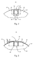
- the z. B. from a can be made of inexpensive unalloyed C22 steel is advantageously a corrosion-resistant protective layer 33 is applied, wherein the protective layer 33 z. B.
- an in A coating which can be applied by a high-speed flame spraying method on one Base of nickel or iron-austenite-cobalt or one in a flame spraying process can be coated coating of titanium oxide.
- This protective layer 33 can also wholly or partially directed to the lateral surface 07 of the bale 02 face 34 of the Cover profile body 04. After the application of the protective layer 33, the entire coated lateral surface 07 of the bale 02 preferably over-turned or ground, whereby the end face 34 of the profile body 04 in whole or in part by the Protective layer 33 is exposed again and a continuous, smooth transition from Profile body 04 to the lateral surface 07 of the bale 02 is ensured.
- the rotating body 01 occurs on the bale 02 applied elevator 03 only with corrosion-resistant surfaces in contact because both the lateral surface 07 of the Bale 02 and the profile body 04 each at least at the contact surfaces with the Elevator 03 are formed corrosion resistant.
- a third embodiment of the rotary body 01 is shown, in which on a surface 29 of a main body 28 of the bale 02 a cover 36th is applied.
- the main body 28 together with its surface 29 of a for Corrosion prone, inexpensive material, eg. B. from a non-alloyed C22 steel consist.
- the cover 36 preferably consists of a corrosion resistant material, eg. B. an alloyed, corrosion-resistant steel and is cohesively applied to the surface 29 of the body 28, preferably welded, in particular by electron beam welding or by Laser welding. These preferred welding methods allow it because of their Depth effect that through the cover 36, the radial material thickness, d. H.
- Welding zones 32 which are shown in simplified form in FIGS. 4 to 6 by lines, are along the circumference of the bale 02 or its base body 28 preferably equidistant trained.
- the tensioning channel 06 which preferably runs in the direction of the length of the bale 02, can - as shown in Fig. 4 - either directly into the main body 28th be incorporated or in the manner previously described in connection with FIG Be formed connection with a profile body 04, wherein the profile body 04 advantageously cohesively, preferably by application of a Welding process, in particular by electron beam welding or by Laser welding, or non-detachably connected by a bond to the base body 28 is.
- the Cover 36 at all points functionally required a slot-shaped opening eleventh to the clamping channel 06, wherein this opening 11 is inserted into the cover 36, is preferably milled, preferably after the cover 36 on the Surface 29 of the body 28 has been applied.
- the slot-shaped opening 11 is thus introduced at least as part of a holding device in the cover 36, wherein with the holding device an attachable on the surface 29 elevator 03 can be held.
- An example of a holding device the Fig. 1, which is why for Details of the holding device is referred to the description in this regard.
- the Slot width S of the opening 11 is in the range of a few millimeters, preferably at most 5 mm, in particular 1 mm to 3 mm (Fig. 1).
- the opening 11 may be extend over the entire length of the bale 02 or only in sections of this length.
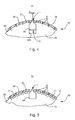
- Figs. 4 and 5 show a particular embodiment the introduced into the main body 28 groove 31, in which a profile body 04 is introduced.
- the groove 31 shown in Figs. 4 and 5 has in the main body 28 a Undercut.
- Such a shape of the groove 31 may, for. B. with a T-shaped Milling cutters are introduced into the main body 28.
- the advantage of the undercut is that a z. B. in the axial direction of the rotating body 01 in the Base 28 inserted profile body 04 by the undercut in the radial Direction of the rotation body 01 against unintentional release from the groove 31st is secured.
- the Fig. 4 can be removed that the bale 02 on its lateral surface 07 final cover 36 has an opening 11 with one compared to the width W31 of Groove 31 smaller slot width S has.
- the ratio of the width W31 of the groove 31 to the slot width S of the opening 11 is preferably between 5: 1 and 15: 1.
- the Slit-shaped opening 11 can, as already mentioned, introduced into the cover 36 are after the cover 36 on the surface 29 of the body 28th has been applied.
- This opening 11 z. B. by milling the in Connection with the Fig. 1 described front edge 18 with the from this edge 18 at the angle ⁇ to the clamping channel 06 extending wall 12 and the rear Edge 19 with the extending approximately perpendicular to the clamping channel 06 towards wall 13 formed or formed on the opening 11.
- Embodiment of this opening 11 is made to the description of FIG. 1.
- a cooling channel 37 may be introduced, which then from the covered on the surface 29 of the body 28 applied cover 36 becomes.
- Flow channels 37 are provided, which preferably equidistant from each other are and the z. B. have a rectangular cross-section.
- Such a design Flow channels 37 can preferably be milled into the main body 28, z. B. with a side milling cutter.
- the flow channels 37 are for temperature control of the lateral surface 07 preferably of a liquid heat transfer medium can be flowed through, for. As of water or an oil. It is advantageous, the flow channels 37 at least partially, d. H. at contact points with the main body 28 lined with a plastic, in particular to the Flow channels 37 flowing through the heat transfer medium relative to the main body 28 thermally isolate. Characterized in that the flow channels 37 in this embodiment of the rotating body 01 can be arranged very close to its lateral surface 07, can a very efficient tempering be realized, especially if also the Cover 36 thin-walled, d. H. only a few millimeters, preferably at most 10 mm is highly trained. As shown in FIG.
- both at least one clamping channel 06 and at least one Flow channel 37 or more flow channels 37 may be formed, which preferably parallel to each other and in the direction of the length of the bale 02 or its Base body 28 extend.
- multiple flow channels 37 is between adjacent flow channels 37 preferably each a weld zone 32nd educated.
- Also between a clamping channel 06 and an adjacent Flow channel 37 is preferably a weld zone 32 is formed. It is advantageous the weld zones 32 along the circumference of the bale 02 to arrange equidistant.
- Welding processes with very narrow heating zones have the advantage that despite this heat feeding manufacturing process of the rotating body 01 practically remains distortion-free. Even in the flow channels 37 mounted linings Plastic are preferred by the heat input in the proposed Welding process not deformed.
- the cover 36 is preferably formed as a tubular hollow cylinder and can be pushed onto the base 28 for its mounting.
- the cover 36 may also be cup-shaped, in particular multi-part, wherein a plurality of arcuate segments in the direction of the circumference on the surface 29 of the Main body 28 are applied.
- the cover 36 preferably from a corrosion-resistant and advantageously also from a wear-resistant material is made, for the main body 28 of the rotating body 01, the z. B. from a cheaper unalloyed and non-corrosion resistant material consists, produced in a manufacturing technology favorable way a noble lateral surface 07 become.
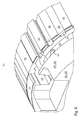
- FIG. 6 shows a part of the rotation body 01 in a perspective view.
- Axial to the length of the body of revolution 01 are on the surface 07; 29 of its bales 02 or main body 28 at least one clamping channel 06 and more preferably equidistant spaced flow channels 37 as z.
- the profile body 04 whose Construction depth less than the substantially radially in the bale 02 or body 28 extending depth of the respective grooves is formed, is preferably positively inserted respectively in one of the grooves and cohesively, in particular by Application of the electron welding method, with the bale 02 or main body 28th connected.
- the grooves formed as flow channels 37 are in the operating state of the rotating body 01 flows through a heat transfer medium and are from Profile body 04 to the surface 07; 29 of the bale 02 or body 28 hermetically closed, whereas the clamping channel 06 with a holding device, such as by way of example shown in Figure 1, equipped and the surface 07; 29 of the bale 02 or Main body 28 at least in part with a z. B.
- At least some Flow channels 37 are z. B. by a on the circumference of the bale 02 or body 28 formed groove 43 preferably near a front side of the rotating body 01st connected to each other, this groove 43 also preferably by a Profile body 04 to the surface 07; 29 of the bale 02 or body 28 hermetically is completed, but this profile body 04 is preferably cylindrical or cup-shaped or ring segment-shaped.
- this on the circumference of Bale 02 or main body 28 formed groove 43 may have one or more Radial holes 44 open as inlet or outlet for the heat transfer medium.
- the Surface 07; 29 of the bale 02 or body 28 After inserting and securing the profile body 04 in the respective grooves is the Surface 07; 29 of the bale 02 or body 28 preferably over-turned and / or ground and then protected against corrosion. Also, the Wear resistance of the surface 07; 29 of the bale 02 or body 28 z. B. by applying a protective layer (as already described for Fig. 3) improved become.
- the Corrosion resistance and wear resistance of the surface 29 of the body 28 preferably be improved by a lateral surface 07 of the Rotational body 01 forming, z. B. tubular cover 36 of a preferably corrosion resistant and wear resistant material on the surface 29 of the Basic body 28 z. B. deferred and z. B.
Landscapes
- Engineering & Computer Science (AREA)
- Mechanical Engineering (AREA)
- Optics & Photonics (AREA)
- Physics & Mathematics (AREA)
- Supply, Installation And Extraction Of Printed Sheets Or Plates (AREA)
- Treatment Of Fiber Materials (AREA)
- Rolls And Other Rotary Bodies (AREA)
- Welding Or Cutting Using Electron Beams (AREA)
- Coating By Spraying Or Casting (AREA)
- Storage Of Harvested Produce (AREA)
- Pressure Welding/Diffusion-Bonding (AREA)
- Application Of Or Painting With Fluid Materials (AREA)
- Ropes Or Cables (AREA)
- Transition And Organic Metals Composition Catalysts For Addition Polymerization (AREA)
- Printing Methods (AREA)
- Perforating, Stamping-Out Or Severing By Means Other Than Cutting (AREA)
- Coating Apparatus (AREA)
- Rotary Presses (AREA)
Abstract
Description
- Fig. 1
- einen in den Ballen des Rotationskörpers eingebrachten Profilkörper mit einem in ihm verlaufenden Spannkanal;
- Fig. 2
- einen Rotationskörper mit einem in den Ballen eingeschweißten Profilkörper;
- Fig. 3
- einen Rotationskörper mit einem in den Ballen eingeschweißten Profilkörper und mit einer auf dem Ballen aufgetragenen Schutzschicht;
- Fig. 4
- einen Rotationskörper mit einer auf dem Grundkörper aufgebrachten Abdeckung;
- Fig. 5
- einen Rotationskörper mit einer auf dem Grundkörper aufgebrachten Abdeckung und mit im Grundkörper zusätzlich zum Spannkanal ausgebildeten Strömungskanälen;
- Fig. 6
- eine perspektivische Ansicht eines Rotationskörpers mit im Ballen bzw. im Grundkörper ausgebildeten Strömungskanälen und mindestens einem Spannkanal, wobei die Strömungskanäle und der Spannkanal an der Mantelfläche des Ballens bzw. an der Oberfläche des Grundkörpers jeweils von einem Profilkörper abgedeckt sind.
- 01
- Rotationskörper, Zylinder, Walze, Formzylinder, Übertragungszylinder
- 02
- Ballen
- 03
- Aufzug, Druckform, Gummidrucktuch
- 04
- Profilkörper
- 05
- -
- 06
- Spannkanal
- 07
- Mantelfläche, Oberfläche
- 08
- Schenkel
- 09
- Schenkel
- 10
- -
- 11
- Öffnung
- 12
- Wandung
- 13
- Wandung
- 14
- Boden
- 15
- -
- 16
- vorlaufendes Ende
- 17
- nachlaufendes Ende
- 18
- vordere Kante
- 19
- hintere Kante
- 20
- -
- 21
- Nut
- 22
- Haltemittel, Leiste; Hebel
- 23
- erstes Ende
- 24
- zweites Ende
- 25
- -
- 26
- Feder
- 27
- Stellmittel, Schlauch
- 28
- Grundkörper
- 29
- Oberfläche (28)
- 30
- -
- 31
- Nut
- 32
- Schweißzone
- 33
- Schutzschicht (02)
- 34
- Stirnseite (04)
- 35
- -
- 36
- Abdeckung
- 37
- Strömungskanal, Kühlkanal
- 38
- Außenkörper
- 39
- Stirnseite
- 40
- -
- 41
- Zone
- 42
- Zone
- 43
- Nut
- 44
- Radialbohrung
- 45
- -
- 46
- Steg
- a
- Überstand (04)
- B
- Breite (21)
- D
- Dicke (22)
- P
- Produktionsrichtung (01)
- S
- Schlitzweite (11)
- t
- Tiefe (06)
- T
- Tangente
- W31
- Weite (31)
- α
- Öffnungswinkel
- β
- Öffnungswinkel
Claims (19)
- Rotationskörper (01) einer Druckmaschine mit einem Ballen (02) mit einem Profilkörper (04), wobei der Profilkörper (04) in einer an einer Mantelfläche (07) des Ballens (02) ausgebildeten Nut (31) eingesetzt und an in Richtung des Umfangs des Ballens (02) voneinander beabstandeten Fügeflächen mit dem Ballen (02) verschweißt ist, wobei der Profilkörper (04) die Nut (31) an der Mantelfläche (07) zumindest teilweise abdeckt, dadurch gekennzeichnet, dass eine Bautiefe des Profilkörpers (04) geringer als eine sich im Wesentlichen radial in den Ballen (02) erstreckende Tiefe der Nut (31) ausgebildet ist.
- Rotationskörper (01) nach Anspruch 1, dadurch gekennzeichnet, dass die Nut (31) als ein von einem Wärmeträgermedium durchströmter Strömungskanal (37) ausgebildet ist und dass der Profilkörper (04) die Nut (31) zur Mantelfläche (07) verschließt.
- Rotationskörper (01) nach Anspruch 1, dadurch gekennzeichnet, dass in der Nut (31) mindestens ein Haltemittel (22) zum Halten eines Aufzugs (03) auf der Mantelfläche (07) des Ballens (02) angeordnet ist und der die Nut (31) abdeckende Profilkörper (04) eine die Nut (31) zur Mantelfläche (07) teilweise öffnende schlitzförmige Öffnung (11) aufweist.
- Rotationskörper (01) nach Anspruch 9 oder 12, dadurch gekennzeichnet, dass sich die Nut (31) in axialer Richtung des Rotationskörpers (01) erstreckt.
- Rotationskörper (01) nach Anspruch 1, dadurch gekennzeichnet, dass sich die Nut (31) zumindest teilweise in Umfangsrichtung des Rotationskörpers (01) erstreckt.
- Rotationskörper (01) nach Anspruch 5, dadurch gekennzeichnet, dass die sich in Umfangsrichtung des Rotationskörpers (01) erstreckende Nut (31) als ein mehrere in axialer Richtung des Rotationskörpers (01) verlaufende Strömungskanäle (37) miteinander verbindender Strömungskanal (37) ausgebildet ist.
- Rotationskörper (01) nach Anspruch 1, dadurch gekennzeichnet, dass der Profilkörper (04) als ein Formteil ausgebildet ist.
- Rotationskörper (01) nach Anspruch 1, dadurch gekennzeichnet, dass der Profilkörper (04) in axialer Richtung des Rotationskörpers (01) leistenförmig ausgebildet ist.
- Rotationskörper (01) nach Anspruch 1, dadurch gekennzeichnet, dass in axialer Richtung des Rotationskörpers (01) mehrere Profilkörper (04) vorgesehen sind.
- Rotationskörper (01) nach Anspruch 1, dadurch gekennzeichnet, dass der Profilkörper (04) aus einem korrosionsbeständigen Werkstoff besteht.
- Rotationskörper (01) nach Anspruch 10, dadurch gekennzeichnet, dass der Profilkörper (04) aus einem Edelstahl besteht.
- Rotationskörper (01) nach Anspruch 1, dadurch gekennzeichnet, dass zumindest ein der Mantelfläche (07) naher Teil zumindest einer der Fügeflächen zwischen dem Ballen (02) und dem Profilkörper (04) glattwandig und in einem Schnitt quer zur axialen Richtung des Rotationskörpers (01) ungekrümmt ausgebildet ist.
- Rotationskörper (01) nach Anspruch 1, dadurch gekennzeichnet, dass die Nut (31) einen Spannkanal (06) mit einem runden oder einem rechteckigen Querschnitt ausbildet.
- Rotationskörper (01) nach Anspruch 1, dadurch gekennzeichnet, dass der Ballen (02) eine die Mantelfläche (07) des Rotationskörpers (01) bildende, die Oberfläche (29) eines Grundkörpers (28) abdeckende Abdeckung (36) aufweist, wobei die einen Spannkanal (06) oder einen Strömungskanal (37) bildenden Nuten im Grundkörper (28) ausgebildet und an der Oberfläche (29) des Grundkörpers (28) jeweils von einem in der jeweiligen Nut angeordneten Profilkörper (04) zumindest teilweise abgedeckt sind.
- Rotationskörper (01) nach Anspruch 1, dadurch gekennzeichnet, dass der Profilkörper (04) mittels Elektronenstrahlschweißen verschweißt ist.
- Rotationskörper (01) nach Anspruch 1, dadurch gekennzeichnet, dass der Profilkörper (04) anstatt durch Schweißen durch Hartlöten im Vakuum mit dem Grundkörper (28) verbunden ist.
- Rotationskörper (01) nach Anspruch 1, dadurch gekennzeichnet, dass der Ballen (02) aus einem für Korrosion anfälligen Werkstoff besteht.
- Rotationskörper (01) nach Anspruch 1, dadurch gekennzeichnet, dass die Mantelfläche (07) des Ballens (02) mit einer korrosionsfesten Schutzschicht (33) überzogen ist.
- Rotationskörper (01) nach Anspruch 18, dadurch gekennzeichnet, dass die Schutzschicht (33) ganz oder zumindest teilweise eine zur Mantelfläche (07) gerichtete Stirnseite (34) des Profilkörpers (04) abdeckt.
Applications Claiming Priority (3)
| Application Number | Priority Date | Filing Date | Title |
|---|---|---|---|
| DE10250684 | 2002-10-31 | ||
| DE10250684A DE10250684B3 (de) | 2002-10-31 | 2002-10-31 | Verfahren zur Herstellung eines Rotationskörpers und Rotationskörper einer Druckmaschine |
| EP03776817A EP1556223B1 (de) | 2002-10-31 | 2003-10-23 | Verfahren zur herstellung eines rotationskörpers |
Related Parent Applications (1)
| Application Number | Title | Priority Date | Filing Date |
|---|---|---|---|
| EP03776817A Division EP1556223B1 (de) | 2002-10-31 | 2003-10-23 | Verfahren zur herstellung eines rotationskörpers |
Publications (3)
| Publication Number | Publication Date |
|---|---|
| EP1574333A2 true EP1574333A2 (de) | 2005-09-14 |
| EP1574333A3 EP1574333A3 (de) | 2007-09-19 |
| EP1574333B1 EP1574333B1 (de) | 2009-12-09 |
Family
ID=31969759
Family Applications (2)
| Application Number | Title | Priority Date | Filing Date |
|---|---|---|---|
| EP03776817A Expired - Lifetime EP1556223B1 (de) | 2002-10-31 | 2003-10-23 | Verfahren zur herstellung eines rotationskörpers |
| EP05103123A Expired - Lifetime EP1574333B1 (de) | 2002-10-31 | 2003-10-23 | Rotationskörper einer Druckmaschine |
Family Applications Before (1)
| Application Number | Title | Priority Date | Filing Date |
|---|---|---|---|
| EP03776817A Expired - Lifetime EP1556223B1 (de) | 2002-10-31 | 2003-10-23 | Verfahren zur herstellung eines rotationskörpers |
Country Status (8)
| Country | Link |
|---|---|
| US (1) | US7766806B2 (de) |
| EP (2) | EP1556223B1 (de) |
| JP (2) | JP4320301B2 (de) |
| CN (1) | CN100484760C (de) |
| AT (2) | ATE451239T1 (de) |
| AU (1) | AU2003286107A1 (de) |
| DE (3) | DE10250684B3 (de) |
| WO (1) | WO2004039591A1 (de) |
Families Citing this family (11)
| Publication number | Priority date | Publication date | Assignee | Title |
|---|---|---|---|---|
| DE102004020694A1 (de) * | 2004-04-28 | 2005-11-24 | Heidelberger Druckmaschinen Ag | Vorrichtung zum Klemmen und Halten einer Druckplatte auf einer Druckplatte auf einer Belichtungstrommel |
| DE102004034049A1 (de) | 2004-07-13 | 2006-02-09 | Man Roland Druckmaschinen Ag | Formzylinder einer Rollenrotationsdruckmaschine |
| EP1637326A2 (de) * | 2004-09-16 | 2006-03-22 | Koenig & Bauer Aktiengesellschaft | Offsetdruckwerk mit einem elastischen Aufzug auf einem Übertragungszylinder |
| DE102004056388B3 (de) * | 2004-09-17 | 2006-04-13 | Koenig & Bauer Ag | Druckwerk einer Offsetdruckmaschine mit mindestens einem Formzylinder, einem Übertragungszylinder und einem Gegendruckzylinder |
| DE102005004556B3 (de) * | 2005-02-01 | 2006-06-14 | Koenig & Bauer Ag | Vorrichtung und Verfahren zur Herstellung von Kantenformen, vorzugsweise Radien an Spannkanälen von Rotationszylindern |
| DE102006017222A1 (de) * | 2005-06-28 | 2007-01-04 | Koenig & Bauer Ag | Zylinder einer Rotationsdruckmaschine mit mindestens einem sich in Axialrichtung dieses Zylinders unter dessen Mantelfläche erstreckenden Kanal |
| DE102007014323B3 (de) * | 2007-03-26 | 2008-03-06 | Koenig & Bauer Aktiengesellschaft | System bestehend aus einem Formzylinder und zumindest einer Zuführeinrichtung für auf dem Formzylinder anzuordnende Druckformen |
| US8176845B2 (en) * | 2006-09-01 | 2012-05-15 | Koenig & Bauer Aktiengesellschaft | Form cylinder of a printing press comprising a plurality of sections in series on its circumferential surface in its axial direction, and printing couple comprising such form cylinder |
| DE102009047674A1 (de) * | 2009-12-08 | 2011-06-09 | Manroland Ag | Druckwerk einer Druckmaschine und Verfahren zum Wechseln mindestens einer Druckplatte an einem solchen Druckwerk |
| DE102010001471B4 (de) | 2010-02-02 | 2020-01-23 | Koenig & Bauer Ag | Zylinder einer Druckmaschine und ein Verfahren zum Umrüsten eines Zylinders für eine Druckmaschine |
| JP5843435B2 (ja) * | 2010-10-18 | 2016-01-13 | 三菱重工印刷紙工機械株式会社 | 印刷胴、印刷ユニット、印刷機並びに印刷胴の製造方法 |
Family Cites Families (41)
| Publication number | Priority date | Publication date | Assignee | Title |
|---|---|---|---|---|
| DD53706A (de) * | ||||
| DE57859C (de) | E. MÜLLER in Amöneburg b. Biebrich a. Rhein | Verschlufs an Traghaken für Kleidungsstücke u. dergl | ||
| DE53706C (de) | F. NAU-MANN in Cöthen, Wallstr. 24 | Rotirende Schaukel | ||
| CH422831A (de) | 1963-09-06 | 1966-10-31 | Maschf Augsburg Nuernberg Ag | Farbwalze für Druckmaschinen |
| US3359899A (en) * | 1965-02-01 | 1967-12-26 | Cottrell Company | Spring tensioned wrap-around plate cylinder clamping arrangement |
| DD66630A1 (de) * | 1967-06-15 | 1969-05-05 | Herbert Doliner | Zylinder für Druckmaschinen |
| US3715981A (en) * | 1970-06-29 | 1973-02-13 | Hamilton Tool Co | Fluid actuator and lock for printing plate cylinders |
| US3893394A (en) * | 1973-03-28 | 1975-07-08 | Wood Industries Inc | Blanket cylinder slot arrangement |
| DE3110982A1 (de) * | 1981-03-20 | 1982-10-07 | M.A.N.- Roland Druckmaschinen AG, 6050 Offenbach | Plattenzylinder mit einer plattenbefestigungsvorrichtung |
| DE3345369A1 (de) * | 1983-12-15 | 1985-06-27 | M.A.N.- Roland Druckmaschinen AG, 6050 Offenbach | Einrichtung zur befestigung einer druckplatte am plattenzylinder einer druckmaschine |
| DE3702032A1 (de) * | 1987-01-24 | 1988-08-04 | Basf Ag | Vorrichtung zum spannen von druckplatten |
| DE3731779A1 (de) * | 1987-09-22 | 1989-03-30 | Koenig & Bauer Ag | Vorrichtung zum aufspannen von biegsamen druckplatten auf formzylinder von rotationsdruckmaschinen |
| DE3738568A1 (de) * | 1987-11-13 | 1989-05-24 | Basf Ag | Vorrichtung zum spannen von druckplatten |
| JPH04130839A (ja) | 1990-09-21 | 1992-05-01 | Nec Corp | 電子メールのキーワード検索方式 |
| US5357863A (en) * | 1991-11-15 | 1994-10-25 | Day International, Inc. | Printing blanket for use with a printing cylinder to achieve a narrow gap lock-up |
| DE4210778C2 (de) * | 1992-04-01 | 1994-03-31 | Roland Man Druckmasch | Sicherungsvorrichtung für Spannschienen zum Spannen von Gummitüchern |
| DE9317726U1 (de) * | 1992-12-24 | 1994-02-03 | Koenig & Bauer AG, 97080 Würzburg | Spindel |
| DE4244077C2 (de) * | 1992-12-24 | 1995-06-08 | Koenig & Bauer Ag | Vorrichtung zum Aufspannen von biegsamen Druckplatten auf einen Formzylinder einer Rotationsdruckmaschine |
| GB9301570D0 (en) * | 1993-01-27 | 1993-03-17 | Lin Pac Containers Int | Printing cylinder assembly |
| DE4315996C1 (de) * | 1993-05-13 | 1994-08-04 | Roland Man Druckmasch | Registereinrichtung für eine hülsenförmige Offset-Druckform |
| DE4319167C2 (de) * | 1993-06-09 | 1995-04-27 | Roland Man Druckmasch | Vorrichtung zum Befestigen einer biegsamen Druckplatte |
| DE4326251C2 (de) * | 1993-08-05 | 1997-08-28 | Koenig & Bauer Albert Ag | Gummi-/Drucktuchzylinder |
| DE4326250C2 (de) * | 1993-08-05 | 1996-05-15 | Koenig & Bauer Albert Ag | Spannvorrichtung in einer Rotationsdruckmaschine |
| DE9408328U1 (de) | 1994-05-20 | 1994-07-21 | Maschinenfabrik Goebel Gmbh, 64293 Darmstadt | Formzylinder |
| FR2727350B1 (fr) * | 1994-11-24 | 1997-02-14 | Heidelberg Harris Sa | Dispositif de fixation d'une forme d'impression souple |
| JP3122330B2 (ja) | 1995-04-20 | 2001-01-09 | 三菱重工業株式会社 | ブランケット胴 |
| FR2737149B1 (fr) * | 1995-07-25 | 1997-10-17 | Heidelberg Harris Sa | Dispositif de fixation d'une plaque d'impression sur un cylindre porte-plaque |
| JPH09216333A (ja) | 1996-02-14 | 1997-08-19 | Komori Corp | 印刷機の印刷シリンダー |
| DE19611642C2 (de) * | 1996-03-25 | 2002-07-18 | Roland Man Druckmasch | Vorrichtung zum Befestigen einer Bespannung auf einem Druckwerkzylinder |
| JPH1120131A (ja) * | 1997-07-03 | 1999-01-26 | Ryobi Ltd | 印刷機の刷版咥え装置 |
| DE19924784C2 (de) * | 1999-05-29 | 2001-05-31 | Koenig & Bauer Ag | Vorrichtung zum Befestigen von biegsamen Platten auf einem Zylinder einer Rotationsdruckmaschine mit Drehrichtungsumkehr |
| DE19924786B4 (de) * | 1999-05-29 | 2004-11-04 | Koenig & Bauer Ag | Vorrichtung zum Befestigen einer biegsamen Platte auf einem Zylinder einer Rotationsdruckmaschine |
| JP3884957B2 (ja) * | 1999-10-08 | 2007-02-21 | ケーニツヒ ウント バウエル アクチエンゲゼルシヤフト | 輪転印刷機の胴 |
| DE10112761A1 (de) * | 2000-04-13 | 2001-10-18 | Heidelberger Druckmasch Ag | Verfahren zum Gebrauch einer Druckplatte |
| DE10058996C1 (de) * | 2000-11-28 | 2002-06-13 | Koenig & Bauer Ag | Vorrichtung zur Befestigung eines Aufzuges |
| DE10218474A1 (de) * | 2002-04-25 | 2003-11-20 | Koenig & Bauer Ag | Vorrichtungen zum Befestigen von mindestens einem Aufzug auf einem Zylinder einer Rotationsdruckmaschine und ein Druckwerk mit dieser Vorrichtung |
| DE10236867B3 (de) * | 2002-08-12 | 2004-03-25 | Koenig & Bauer Ag | Vorrichtung zum Halten mindestens eines Aufzugs auf einem Zylinder einer Rotationsdruckmaschine |
| FR2844743B1 (fr) * | 2002-09-19 | 2004-12-17 | Goss Systemes Graphiques Nante | Ensemble comprenant une unite de blanchet et un cylindre a dispositif de fixation de blanchet, cylindre, unite de blanchet et presse offset correspondants |
| DE102004042342B4 (de) * | 2004-09-01 | 2008-02-14 | Maschinenfabrik Wifag | Spanneinrichtung für einen Spannkanal eines Zylinderkörpers, Druckformzylinder und Verfahren zur Herstellung |
| KR100723413B1 (ko) | 2005-11-25 | 2007-05-30 | 삼성전자주식회사 | 데이터 기록 및 읽기용 멀티 프로브와 그 동작 방법 |
| DE102007054935A1 (de) * | 2007-11-17 | 2009-05-20 | Manroland Ag | Druckmaschinenzylinder |
-
2002
- 2002-10-31 DE DE10250684A patent/DE10250684B3/de not_active Expired - Fee Related
-
2003
- 2003-10-23 AT AT03776817T patent/ATE451239T1/de not_active IP Right Cessation
- 2003-10-23 JP JP2004547415A patent/JP4320301B2/ja not_active Expired - Fee Related
- 2003-10-23 AU AU2003286107A patent/AU2003286107A1/en not_active Abandoned
- 2003-10-23 EP EP03776817A patent/EP1556223B1/de not_active Expired - Lifetime
- 2003-10-23 EP EP05103123A patent/EP1574333B1/de not_active Expired - Lifetime
- 2003-10-23 WO PCT/DE2003/003529 patent/WO2004039591A1/de not_active Ceased
- 2003-10-23 CN CNB2003801081133A patent/CN100484760C/zh not_active Expired - Fee Related
- 2003-10-23 DE DE50312220T patent/DE50312220D1/de not_active Expired - Lifetime
- 2003-10-23 DE DE50312214T patent/DE50312214D1/de not_active Expired - Lifetime
- 2003-10-23 AT AT05103123T patent/ATE451234T1/de not_active IP Right Cessation
- 2003-10-23 US US10/532,866 patent/US7766806B2/en not_active Expired - Fee Related
-
2009
- 2009-02-18 JP JP2009035463A patent/JP5021686B2/ja not_active Expired - Fee Related
Non-Patent Citations (1)
| Title |
|---|
| None |
Also Published As
| Publication number | Publication date |
|---|---|
| EP1574333B1 (de) | 2009-12-09 |
| JP4320301B2 (ja) | 2009-08-26 |
| DE50312214D1 (de) | 2010-01-21 |
| EP1556223B1 (de) | 2009-12-09 |
| JP5021686B2 (ja) | 2012-09-12 |
| AU2003286107A1 (en) | 2004-05-25 |
| US20060150410A1 (en) | 2006-07-13 |
| CN1732085A (zh) | 2006-02-08 |
| JP2006504551A (ja) | 2006-02-09 |
| CN100484760C (zh) | 2009-05-06 |
| EP1574333A3 (de) | 2007-09-19 |
| JP2009101711A (ja) | 2009-05-14 |
| DE50312220D1 (de) | 2010-01-21 |
| WO2004039591A1 (de) | 2004-05-13 |
| ATE451234T1 (de) | 2009-12-15 |
| ATE451239T1 (de) | 2009-12-15 |
| DE10250684B3 (de) | 2004-04-01 |
| EP1556223A1 (de) | 2005-07-27 |
| US7766806B2 (en) | 2010-08-03 |
Similar Documents
| Publication | Publication Date | Title |
|---|---|---|
| EP1554207B1 (de) | Falzapparat | |
| EP1337401B1 (de) | Zylinder einer rotationsdruckmaschine mit einer vorrichtung zur befestigung eines aufzuges | |
| EP2603340B1 (de) | Werkzeughalter | |
| EP1574333B1 (de) | Rotationskörper einer Druckmaschine | |
| DE2610200C3 (de) | Beschlag zum lösbaren Verbinden zweier Bauteile, insbesondere von plattenförmigen Bauteilen für Möbel | |
| WO2005123269A1 (de) | Rakelvorrichtung | |
| DE3507929A1 (de) | Messerzylinder zum bearbeiten von bahnfoermigem gut | |
| EP0803606A2 (de) | Durchbiegungsausgleichswalze | |
| DE10262010B4 (de) | Verfahren zur Herstellung eines Rotationskörpers einer Druckmaschine | |
| EP1569798B1 (de) | Rotationskörper einer druckmaschine und verfahren zu dessen herstellung | |
| DE102004054997B4 (de) | Zylinder einer Druckmaschine mit mindestens einem Spannkanal | |
| DE10250706B3 (de) | Rotationskörper einer Druckmaschine | |
| DE10255707B4 (de) | Rotationskörper einer Druckmaschine mit mindestens einem Hohlraum | |
| DE102004001397A1 (de) | Zylinder einer Druckmaschine mit mindestens einem Spannkanal und ein Verfahren zur Herstellung eines Zylinders | |
| DE69508346T2 (de) | Farbzuführvorrichtung für eine Schablonendruckmaschine | |
| DE19950643A1 (de) | Gummizylinderhülse, insbesondere für Offset-Rollenrotationsdruckmaschinen | |
| DE102004001398B4 (de) | Verfahren zur Herstellung einer Öffnung an der Mantelfläche eines Zylinders einer Druckmaschine und Zylinder | |
| DE69611998T2 (de) | Stange eines gepäckträgers und verfahren zur herstellung | |
| EP2377686B1 (de) | Hülse zur Montage auf einen Druckmaschinenzylinder | |
| DE4447179A1 (de) | Gummituchzylinder für Offsetdruck | |
| EP1528983A1 (de) | Vorrichtungen zum halten mindestens eines aufzugs auf einem zylinder einer rotationsdruckmaschine und ein verfahren zur montage dieser vorrichtungen | |
| EP0671497A2 (de) | Walze, insbesondere für Textilbehandlungmaschinen | |
| EP1685287B1 (de) | Vorrichtung an einer von aussen nach innen durchströmten siebtrommel | |
| DE102006027142B3 (de) | Drucktucheinheit für einen Drucktuchzylinder einer Rotationsdruckmaschine | |
| DE102004049514B4 (de) | Druckeinheit mit wenigstens einem Formzylinder und wenigstens einer Farbauftragswalze |
Legal Events
| Date | Code | Title | Description |
|---|---|---|---|
| PUAI | Public reference made under article 153(3) epc to a published international application that has entered the european phase |
Free format text: ORIGINAL CODE: 0009012 |
|
| AC | Divisional application: reference to earlier application |
Ref document number: 1556223 Country of ref document: EP Kind code of ref document: P |
|
| AK | Designated contracting states |
Kind code of ref document: A2 Designated state(s): AT BE BG CH CY CZ DE DK EE ES FI FR GB GR HU IE IT LI LU MC NL PT RO SE SI SK TR |
|
| AX | Request for extension of the european patent |
Extension state: AL LT LV MK |
|
| PUAL | Search report despatched |
Free format text: ORIGINAL CODE: 0009013 |
|
| AK | Designated contracting states |
Kind code of ref document: A3 Designated state(s): AT BE BG CH CY CZ DE DK EE ES FI FR GB GR HU IE IT LI LU MC NL PT RO SE SI SK TR |
|
| AX | Request for extension of the european patent |
Extension state: AL LT LV MK |
|
| RIC1 | Information provided on ipc code assigned before grant |
Ipc: B41F 13/08 20060101AFI20050727BHEP Ipc: B41F 13/10 20060101ALI20070816BHEP Ipc: B41F 13/193 20060101ALI20070816BHEP |
|
| 17P | Request for examination filed |
Effective date: 20070910 |
|
| AKX | Designation fees paid |
Designated state(s): AT BE BG CH CY CZ DE DK EE ES FI FR GB GR HU IE IT LI LU MC NL PT RO SE SI SK TR |
|
| GRAP | Despatch of communication of intention to grant a patent |
Free format text: ORIGINAL CODE: EPIDOSNIGR1 |
|
| GRAS | Grant fee paid |
Free format text: ORIGINAL CODE: EPIDOSNIGR3 |
|
| GRAA | (expected) grant |
Free format text: ORIGINAL CODE: 0009210 |
|
| RIN1 | Information on inventor provided before grant (corrected) |
Inventor name: SCHAEFER, KARL Inventor name: FELGENHAUER, WOLFGANG Inventor name: BECKER, MARTIN Inventor name: SCHNEIDER, GEORG |
|
| AC | Divisional application: reference to earlier application |
Ref document number: 1556223 Country of ref document: EP Kind code of ref document: P |
|
| AK | Designated contracting states |
Kind code of ref document: B1 Designated state(s): AT BE BG CH CY CZ DE DK EE ES FI FR GB GR HU IE IT LI LU MC NL PT RO SE SI SK TR |
|
| REG | Reference to a national code |
Ref country code: GB Ref legal event code: FG4D Free format text: NOT ENGLISH |
|
| REG | Reference to a national code |
Ref country code: CH Ref legal event code: EP |
|
| REG | Reference to a national code |
Ref country code: IE Ref legal event code: FG4D |
|
| REF | Corresponds to: |
Ref document number: 50312220 Country of ref document: DE Date of ref document: 20100121 Kind code of ref document: P |
|
| REG | Reference to a national code |
Ref country code: NL Ref legal event code: VDEP Effective date: 20091209 |
|
| PG25 | Lapsed in a contracting state [announced via postgrant information from national office to epo] |
Ref country code: SE Free format text: LAPSE BECAUSE OF FAILURE TO SUBMIT A TRANSLATION OF THE DESCRIPTION OR TO PAY THE FEE WITHIN THE PRESCRIBED TIME-LIMIT Effective date: 20091209 Ref country code: FI Free format text: LAPSE BECAUSE OF FAILURE TO SUBMIT A TRANSLATION OF THE DESCRIPTION OR TO PAY THE FEE WITHIN THE PRESCRIBED TIME-LIMIT Effective date: 20091209 |
|
| PG25 | Lapsed in a contracting state [announced via postgrant information from national office to epo] |
Ref country code: SI Free format text: LAPSE BECAUSE OF FAILURE TO SUBMIT A TRANSLATION OF THE DESCRIPTION OR TO PAY THE FEE WITHIN THE PRESCRIBED TIME-LIMIT Effective date: 20091209 |
|
| REG | Reference to a national code |
Ref country code: IE Ref legal event code: FD4D |
|
| PG25 | Lapsed in a contracting state [announced via postgrant information from national office to epo] |
Ref country code: EE Free format text: LAPSE BECAUSE OF FAILURE TO SUBMIT A TRANSLATION OF THE DESCRIPTION OR TO PAY THE FEE WITHIN THE PRESCRIBED TIME-LIMIT Effective date: 20091209 Ref country code: RO Free format text: LAPSE BECAUSE OF FAILURE TO SUBMIT A TRANSLATION OF THE DESCRIPTION OR TO PAY THE FEE WITHIN THE PRESCRIBED TIME-LIMIT Effective date: 20091209 Ref country code: PT Free format text: LAPSE BECAUSE OF FAILURE TO SUBMIT A TRANSLATION OF THE DESCRIPTION OR TO PAY THE FEE WITHIN THE PRESCRIBED TIME-LIMIT Effective date: 20100409 Ref country code: NL Free format text: LAPSE BECAUSE OF FAILURE TO SUBMIT A TRANSLATION OF THE DESCRIPTION OR TO PAY THE FEE WITHIN THE PRESCRIBED TIME-LIMIT Effective date: 20091209 Ref country code: IE Free format text: LAPSE BECAUSE OF FAILURE TO SUBMIT A TRANSLATION OF THE DESCRIPTION OR TO PAY THE FEE WITHIN THE PRESCRIBED TIME-LIMIT Effective date: 20091209 Ref country code: ES Free format text: LAPSE BECAUSE OF FAILURE TO SUBMIT A TRANSLATION OF THE DESCRIPTION OR TO PAY THE FEE WITHIN THE PRESCRIBED TIME-LIMIT Effective date: 20100320 Ref country code: BG Free format text: LAPSE BECAUSE OF FAILURE TO SUBMIT A TRANSLATION OF THE DESCRIPTION OR TO PAY THE FEE WITHIN THE PRESCRIBED TIME-LIMIT Effective date: 20100309 |
|
| PG25 | Lapsed in a contracting state [announced via postgrant information from national office to epo] |
Ref country code: CZ Free format text: LAPSE BECAUSE OF FAILURE TO SUBMIT A TRANSLATION OF THE DESCRIPTION OR TO PAY THE FEE WITHIN THE PRESCRIBED TIME-LIMIT Effective date: 20091209 Ref country code: SK Free format text: LAPSE BECAUSE OF FAILURE TO SUBMIT A TRANSLATION OF THE DESCRIPTION OR TO PAY THE FEE WITHIN THE PRESCRIBED TIME-LIMIT Effective date: 20091209 |
|
| PLBE | No opposition filed within time limit |
Free format text: ORIGINAL CODE: 0009261 |
|
| STAA | Information on the status of an ep patent application or granted ep patent |
Free format text: STATUS: NO OPPOSITION FILED WITHIN TIME LIMIT |
|
| PG25 | Lapsed in a contracting state [announced via postgrant information from national office to epo] |
Ref country code: CY Free format text: LAPSE BECAUSE OF FAILURE TO SUBMIT A TRANSLATION OF THE DESCRIPTION OR TO PAY THE FEE WITHIN THE PRESCRIBED TIME-LIMIT Effective date: 20091209 Ref country code: GR Free format text: LAPSE BECAUSE OF FAILURE TO SUBMIT A TRANSLATION OF THE DESCRIPTION OR TO PAY THE FEE WITHIN THE PRESCRIBED TIME-LIMIT Effective date: 20100310 |
|
| 26N | No opposition filed |
Effective date: 20100910 |
|
| PG25 | Lapsed in a contracting state [announced via postgrant information from national office to epo] |
Ref country code: DK Free format text: LAPSE BECAUSE OF FAILURE TO SUBMIT A TRANSLATION OF THE DESCRIPTION OR TO PAY THE FEE WITHIN THE PRESCRIBED TIME-LIMIT Effective date: 20091209 |
|
| BERE | Be: lapsed |
Owner name: KOENIG & BAUER A.G. Effective date: 20101031 |
|
| PG25 | Lapsed in a contracting state [announced via postgrant information from national office to epo] |
Ref country code: MC Free format text: LAPSE BECAUSE OF NON-PAYMENT OF DUE FEES Effective date: 20101031 |
|
| PG25 | Lapsed in a contracting state [announced via postgrant information from national office to epo] |
Ref country code: BE Free format text: LAPSE BECAUSE OF NON-PAYMENT OF DUE FEES Effective date: 20101031 |
|
| REG | Reference to a national code |
Ref country code: AT Ref legal event code: MM01 Ref document number: 451234 Country of ref document: AT Kind code of ref document: T Effective date: 20101023 |
|
| PG25 | Lapsed in a contracting state [announced via postgrant information from national office to epo] |
Ref country code: AT Free format text: LAPSE BECAUSE OF NON-PAYMENT OF DUE FEES Effective date: 20101023 |
|
| PG25 | Lapsed in a contracting state [announced via postgrant information from national office to epo] |
Ref country code: LU Free format text: LAPSE BECAUSE OF NON-PAYMENT OF DUE FEES Effective date: 20101023 Ref country code: HU Free format text: LAPSE BECAUSE OF FAILURE TO SUBMIT A TRANSLATION OF THE DESCRIPTION OR TO PAY THE FEE WITHIN THE PRESCRIBED TIME-LIMIT Effective date: 20100610 |
|
| PG25 | Lapsed in a contracting state [announced via postgrant information from national office to epo] |
Ref country code: TR Free format text: LAPSE BECAUSE OF FAILURE TO SUBMIT A TRANSLATION OF THE DESCRIPTION OR TO PAY THE FEE WITHIN THE PRESCRIBED TIME-LIMIT Effective date: 20091209 |
|
| PGFP | Annual fee paid to national office [announced via postgrant information from national office to epo] |
Ref country code: CH Payment date: 20121025 Year of fee payment: 10 |
|
| PGFP | Annual fee paid to national office [announced via postgrant information from national office to epo] |
Ref country code: IT Payment date: 20121022 Year of fee payment: 10 |
|
| REG | Reference to a national code |
Ref country code: CH Ref legal event code: PL |
|
| PG25 | Lapsed in a contracting state [announced via postgrant information from national office to epo] |
Ref country code: LI Free format text: LAPSE BECAUSE OF NON-PAYMENT OF DUE FEES Effective date: 20131031 Ref country code: CH Free format text: LAPSE BECAUSE OF NON-PAYMENT OF DUE FEES Effective date: 20131031 |
|
| PG25 | Lapsed in a contracting state [announced via postgrant information from national office to epo] |
Ref country code: IT Free format text: LAPSE BECAUSE OF NON-PAYMENT OF DUE FEES Effective date: 20131023 |
|
| REG | Reference to a national code |
Ref country code: DE Ref legal event code: R081 Ref document number: 50312220 Country of ref document: DE Owner name: KOENIG & BAUER AG, DE Free format text: FORMER OWNER: KOENIG & BAUER AKTIENGESELLSCHAFT, 97080 WUERZBURG, DE |
|
| REG | Reference to a national code |
Ref country code: FR Ref legal event code: PLFP Year of fee payment: 13 |
|
| REG | Reference to a national code |
Ref country code: FR Ref legal event code: PLFP Year of fee payment: 14 |
|
| REG | Reference to a national code |
Ref country code: FR Ref legal event code: PLFP Year of fee payment: 15 |
|
| REG | Reference to a national code |
Ref country code: FR Ref legal event code: CA Effective date: 20170922 Ref country code: FR Ref legal event code: CD Owner name: KOENIG & BAUER AG, DE Effective date: 20170922 |
|
| REG | Reference to a national code |
Ref country code: FR Ref legal event code: PLFP Year of fee payment: 16 |
|
| PGFP | Annual fee paid to national office [announced via postgrant information from national office to epo] |
Ref country code: GB Payment date: 20181024 Year of fee payment: 16 Ref country code: FR Payment date: 20181026 Year of fee payment: 16 |
|
| PGFP | Annual fee paid to national office [announced via postgrant information from national office to epo] |
Ref country code: DE Payment date: 20191108 Year of fee payment: 17 |
|
| GBPC | Gb: european patent ceased through non-payment of renewal fee |
Effective date: 20191023 |
|
| PG25 | Lapsed in a contracting state [announced via postgrant information from national office to epo] |
Ref country code: GB Free format text: LAPSE BECAUSE OF NON-PAYMENT OF DUE FEES Effective date: 20191023 Ref country code: FR Free format text: LAPSE BECAUSE OF NON-PAYMENT OF DUE FEES Effective date: 20191031 |
|
| REG | Reference to a national code |
Ref country code: DE Ref legal event code: R119 Ref document number: 50312220 Country of ref document: DE |
|
| PG25 | Lapsed in a contracting state [announced via postgrant information from national office to epo] |
Ref country code: DE Free format text: LAPSE BECAUSE OF NON-PAYMENT OF DUE FEES Effective date: 20210501 |