EP1557582B1 - Stossdämpfungskörper für fahrzeuge - Google Patents
Stossdämpfungskörper für fahrzeuge Download PDFInfo
- Publication number
- EP1557582B1 EP1557582B1 EP03809840A EP03809840A EP1557582B1 EP 1557582 B1 EP1557582 B1 EP 1557582B1 EP 03809840 A EP03809840 A EP 03809840A EP 03809840 A EP03809840 A EP 03809840A EP 1557582 B1 EP1557582 B1 EP 1557582B1
- Authority
- EP
- European Patent Office
- Prior art keywords
- ribs
- recessed
- vehicle
- wall
- absorbing member
- Prior art date
- Legal status (The legal status is an assumption and is not a legal conclusion. Google has not performed a legal analysis and makes no representation as to the accuracy of the status listed.)
- Expired - Lifetime
Links
Images


Classifications
-
- B—PERFORMING OPERATIONS; TRANSPORTING
- B60—VEHICLES IN GENERAL
- B60R—VEHICLES, VEHICLE FITTINGS, OR VEHICLE PARTS, NOT OTHERWISE PROVIDED FOR
- B60R19/00—Wheel guards; Radiator guards, e.g. grilles; Obstruction removers; Fittings damping bouncing force in collisions
- B60R19/02—Bumpers, i.e. impact receiving or absorbing members for protecting vehicles or fending off blows from other vehicles or objects
- B60R19/18—Bumpers, i.e. impact receiving or absorbing members for protecting vehicles or fending off blows from other vehicles or objects characterised by the cross-section; Means within the bumper to absorb impact
-
- B—PERFORMING OPERATIONS; TRANSPORTING
- B60—VEHICLES IN GENERAL
- B60R—VEHICLES, VEHICLE FITTINGS, OR VEHICLE PARTS, NOT OTHERWISE PROVIDED FOR
- B60R21/00—Arrangements or fittings on vehicles for protecting or preventing injuries to occupants or pedestrians in case of accidents or other traffic risks
- B60R21/02—Occupant safety arrangements or fittings, e.g. crash pads
- B60R21/04—Padded linings for the vehicle interior ; Energy absorbing structures associated with padded or non-padded linings
- B60R21/0428—Padded linings for the vehicle interior ; Energy absorbing structures associated with padded or non-padded linings associated with the side doors or panels, e.g. displaced towards the occupants in case of a side collision
-
- F—MECHANICAL ENGINEERING; LIGHTING; HEATING; WEAPONS; BLASTING
- F16—ENGINEERING ELEMENTS AND UNITS; GENERAL MEASURES FOR PRODUCING AND MAINTAINING EFFECTIVE FUNCTIONING OF MACHINES OR INSTALLATIONS; THERMAL INSULATION IN GENERAL
- F16F—SPRINGS; SHOCK-ABSORBERS; MEANS FOR DAMPING VIBRATION
- F16F7/00—Vibration-dampers; Shock-absorbers
- F16F7/12—Vibration-dampers; Shock-absorbers using plastic deformation of members
- F16F7/121—Vibration-dampers; Shock-absorbers using plastic deformation of members the members having a cellular, e.g. honeycomb, structure
-
- F—MECHANICAL ENGINEERING; LIGHTING; HEATING; WEAPONS; BLASTING
- F16—ENGINEERING ELEMENTS AND UNITS; GENERAL MEASURES FOR PRODUCING AND MAINTAINING EFFECTIVE FUNCTIONING OF MACHINES OR INSTALLATIONS; THERMAL INSULATION IN GENERAL
- F16F—SPRINGS; SHOCK-ABSORBERS; MEANS FOR DAMPING VIBRATION
- F16F9/00—Springs, vibration-dampers, shock-absorbers, or similarly-constructed movement-dampers using a fluid or the equivalent as damping medium
- F16F9/02—Springs, vibration-dampers, shock-absorbers, or similarly-constructed movement-dampers using a fluid or the equivalent as damping medium using gas only or vacuum
- F16F9/04—Springs, vibration-dampers, shock-absorbers, or similarly-constructed movement-dampers using a fluid or the equivalent as damping medium using gas only or vacuum in a chamber with a flexible wall
- F16F9/0472—Springs, vibration-dampers, shock-absorbers, or similarly-constructed movement-dampers using a fluid or the equivalent as damping medium using gas only or vacuum in a chamber with a flexible wall characterised by comprising a damping device
- F16F9/0481—Springs, vibration-dampers, shock-absorbers, or similarly-constructed movement-dampers using a fluid or the equivalent as damping medium using gas only or vacuum in a chamber with a flexible wall characterised by comprising a damping device provided in an opening to the exterior atmosphere
-
- B—PERFORMING OPERATIONS; TRANSPORTING
- B29—WORKING OF PLASTICS; WORKING OF SUBSTANCES IN A PLASTIC STATE IN GENERAL
- B29C—SHAPING OR JOINING OF PLASTICS; SHAPING OF MATERIAL IN A PLASTIC STATE, NOT OTHERWISE PROVIDED FOR; AFTER-TREATMENT OF THE SHAPED PRODUCTS, e.g. REPAIRING
- B29C49/00—Blow-moulding, i.e. blowing a preform or parison to a desired shape within a mould; Apparatus therefor
- B29C49/42—Component parts, details or accessories; Auxiliary operations
- B29C49/48—Moulds
- B29C49/4802—Moulds with means for locally compressing part(s) of the parison in the main blowing cavity
- B29C2049/4805—Moulds with means for locally compressing part(s) of the parison in the main blowing cavity by closing the mould halves
-
- B—PERFORMING OPERATIONS; TRANSPORTING
- B29—WORKING OF PLASTICS; WORKING OF SUBSTANCES IN A PLASTIC STATE IN GENERAL
- B29C—SHAPING OR JOINING OF PLASTICS; SHAPING OF MATERIAL IN A PLASTIC STATE, NOT OTHERWISE PROVIDED FOR; AFTER-TREATMENT OF THE SHAPED PRODUCTS, e.g. REPAIRING
- B29C49/00—Blow-moulding, i.e. blowing a preform or parison to a desired shape within a mould; Apparatus therefor
- B29C49/02—Combined blow-moulding and manufacture of the preform or the parison
- B29C49/04—Extrusion blow-moulding
-
- B—PERFORMING OPERATIONS; TRANSPORTING
- B29—WORKING OF PLASTICS; WORKING OF SUBSTANCES IN A PLASTIC STATE IN GENERAL
- B29C—SHAPING OR JOINING OF PLASTICS; SHAPING OF MATERIAL IN A PLASTIC STATE, NOT OTHERWISE PROVIDED FOR; AFTER-TREATMENT OF THE SHAPED PRODUCTS, e.g. REPAIRING
- B29C49/00—Blow-moulding, i.e. blowing a preform or parison to a desired shape within a mould; Apparatus therefor
- B29C49/42—Component parts, details or accessories; Auxiliary operations
- B29C49/48—Moulds
- B29C49/4802—Moulds with means for locally compressing part(s) of the parison in the main blowing cavity
- B29C49/4812—Moulds with means for locally compressing part(s) of the parison in the main blowing cavity and welding opposite wall parts of the parisons or preforms to each other
-
- B—PERFORMING OPERATIONS; TRANSPORTING
- B29—WORKING OF PLASTICS; WORKING OF SUBSTANCES IN A PLASTIC STATE IN GENERAL
- B29K—INDEXING SCHEME ASSOCIATED WITH SUBCLASSES B29B, B29C OR B29D, RELATING TO MOULDING MATERIALS OR TO MATERIALS FOR MOULDS, REINFORCEMENTS, FILLERS OR PREFORMED PARTS, e.g. INSERTS
- B29K2023/00—Use of polyalkenes or derivatives thereof as moulding material
- B29K2023/04—Polymers of ethylene
- B29K2023/06—PE, i.e. polyethylene
-
- B—PERFORMING OPERATIONS; TRANSPORTING
- B29—WORKING OF PLASTICS; WORKING OF SUBSTANCES IN A PLASTIC STATE IN GENERAL
- B29K—INDEXING SCHEME ASSOCIATED WITH SUBCLASSES B29B, B29C OR B29D, RELATING TO MOULDING MATERIALS OR TO MATERIALS FOR MOULDS, REINFORCEMENTS, FILLERS OR PREFORMED PARTS, e.g. INSERTS
- B29K2023/00—Use of polyalkenes or derivatives thereof as moulding material
- B29K2023/10—Polymers of propylene
- B29K2023/12—PP, i.e. polypropylene
-
- B—PERFORMING OPERATIONS; TRANSPORTING
- B29—WORKING OF PLASTICS; WORKING OF SUBSTANCES IN A PLASTIC STATE IN GENERAL
- B29K—INDEXING SCHEME ASSOCIATED WITH SUBCLASSES B29B, B29C OR B29D, RELATING TO MOULDING MATERIALS OR TO MATERIALS FOR MOULDS, REINFORCEMENTS, FILLERS OR PREFORMED PARTS, e.g. INSERTS
- B29K2025/00—Use of polymers of vinyl-aromatic compounds or derivatives thereof as moulding material
-
- B—PERFORMING OPERATIONS; TRANSPORTING
- B29—WORKING OF PLASTICS; WORKING OF SUBSTANCES IN A PLASTIC STATE IN GENERAL
- B29K—INDEXING SCHEME ASSOCIATED WITH SUBCLASSES B29B, B29C OR B29D, RELATING TO MOULDING MATERIALS OR TO MATERIALS FOR MOULDS, REINFORCEMENTS, FILLERS OR PREFORMED PARTS, e.g. INSERTS
- B29K2055/00—Use of specific polymers obtained by polymerisation reactions only involving carbon-to-carbon unsaturated bonds, not provided for in a single one of main groups B29K2023/00 - B29K2049/00, e.g. having a vinyl group, as moulding material
- B29K2055/02—ABS polymers, i.e. acrylonitrile-butadiene-styrene polymers
-
- B—PERFORMING OPERATIONS; TRANSPORTING
- B29—WORKING OF PLASTICS; WORKING OF SUBSTANCES IN A PLASTIC STATE IN GENERAL
- B29K—INDEXING SCHEME ASSOCIATED WITH SUBCLASSES B29B, B29C OR B29D, RELATING TO MOULDING MATERIALS OR TO MATERIALS FOR MOULDS, REINFORCEMENTS, FILLERS OR PREFORMED PARTS, e.g. INSERTS
- B29K2067/00—Use of polyesters or derivatives thereof, as moulding material
-
- B—PERFORMING OPERATIONS; TRANSPORTING
- B29—WORKING OF PLASTICS; WORKING OF SUBSTANCES IN A PLASTIC STATE IN GENERAL
- B29K—INDEXING SCHEME ASSOCIATED WITH SUBCLASSES B29B, B29C OR B29D, RELATING TO MOULDING MATERIALS OR TO MATERIALS FOR MOULDS, REINFORCEMENTS, FILLERS OR PREFORMED PARTS, e.g. INSERTS
- B29K2069/00—Use of PC, i.e. polycarbonates or derivatives thereof, as moulding material
-
- B—PERFORMING OPERATIONS; TRANSPORTING
- B29—WORKING OF PLASTICS; WORKING OF SUBSTANCES IN A PLASTIC STATE IN GENERAL
- B29K—INDEXING SCHEME ASSOCIATED WITH SUBCLASSES B29B, B29C OR B29D, RELATING TO MOULDING MATERIALS OR TO MATERIALS FOR MOULDS, REINFORCEMENTS, FILLERS OR PREFORMED PARTS, e.g. INSERTS
- B29K2995/00—Properties of moulding materials, reinforcements, fillers, preformed parts or moulds
- B29K2995/0037—Other properties
- B29K2995/0089—Impact strength or toughness
-
- B—PERFORMING OPERATIONS; TRANSPORTING
- B29—WORKING OF PLASTICS; WORKING OF SUBSTANCES IN A PLASTIC STATE IN GENERAL
- B29L—INDEXING SCHEME ASSOCIATED WITH SUBCLASS B29C, RELATING TO PARTICULAR ARTICLES
- B29L2031/00—Other particular articles
- B29L2031/30—Vehicles, e.g. ships or aircraft, or body parts thereof
- B29L2031/3005—Body finishings
- B29L2031/3008—Instrument panels
-
- B—PERFORMING OPERATIONS; TRANSPORTING
- B29—WORKING OF PLASTICS; WORKING OF SUBSTANCES IN A PLASTIC STATE IN GENERAL
- B29L—INDEXING SCHEME ASSOCIATED WITH SUBCLASS B29C, RELATING TO PARTICULAR ARTICLES
- B29L2031/00—Other particular articles
- B29L2031/30—Vehicles, e.g. ships or aircraft, or body parts thereof
- B29L2031/3005—Body finishings
- B29L2031/3011—Roof linings
-
- B—PERFORMING OPERATIONS; TRANSPORTING
- B29—WORKING OF PLASTICS; WORKING OF SUBSTANCES IN A PLASTIC STATE IN GENERAL
- B29L—INDEXING SCHEME ASSOCIATED WITH SUBCLASS B29C, RELATING TO PARTICULAR ARTICLES
- B29L2031/00—Other particular articles
- B29L2031/30—Vehicles, e.g. ships or aircraft, or body parts thereof
- B29L2031/3005—Body finishings
- B29L2031/3014—Door linings
-
- B—PERFORMING OPERATIONS; TRANSPORTING
- B29—WORKING OF PLASTICS; WORKING OF SUBSTANCES IN A PLASTIC STATE IN GENERAL
- B29L—INDEXING SCHEME ASSOCIATED WITH SUBCLASS B29C, RELATING TO PARTICULAR ARTICLES
- B29L2031/00—Other particular articles
- B29L2031/30—Vehicles, e.g. ships or aircraft, or body parts thereof
- B29L2031/3005—Body finishings
- B29L2031/302—Trim strips
-
- B—PERFORMING OPERATIONS; TRANSPORTING
- B29—WORKING OF PLASTICS; WORKING OF SUBSTANCES IN A PLASTIC STATE IN GENERAL
- B29L—INDEXING SCHEME ASSOCIATED WITH SUBCLASS B29C, RELATING TO PARTICULAR ARTICLES
- B29L2031/00—Other particular articles
- B29L2031/30—Vehicles, e.g. ships or aircraft, or body parts thereof
- B29L2031/3005—Body finishings
- B29L2031/3023—Head-rests
-
- B—PERFORMING OPERATIONS; TRANSPORTING
- B29—WORKING OF PLASTICS; WORKING OF SUBSTANCES IN A PLASTIC STATE IN GENERAL
- B29L—INDEXING SCHEME ASSOCIATED WITH SUBCLASS B29C, RELATING TO PARTICULAR ARTICLES
- B29L2031/00—Other particular articles
- B29L2031/30—Vehicles, e.g. ships or aircraft, or body parts thereof
- B29L2031/3005—Body finishings
- B29L2031/3026—Arm-rests
-
- B—PERFORMING OPERATIONS; TRANSPORTING
- B29—WORKING OF PLASTICS; WORKING OF SUBSTANCES IN A PLASTIC STATE IN GENERAL
- B29L—INDEXING SCHEME ASSOCIATED WITH SUBCLASS B29C, RELATING TO PARTICULAR ARTICLES
- B29L2031/00—Other particular articles
- B29L2031/30—Vehicles, e.g. ships or aircraft, or body parts thereof
- B29L2031/3044—Bumpers
-
- B—PERFORMING OPERATIONS; TRANSPORTING
- B29—WORKING OF PLASTICS; WORKING OF SUBSTANCES IN A PLASTIC STATE IN GENERAL
- B29L—INDEXING SCHEME ASSOCIATED WITH SUBCLASS B29C, RELATING TO PARTICULAR ARTICLES
- B29L2031/00—Other particular articles
- B29L2031/712—Containers; Packaging elements or accessories, Packages
- B29L2031/7138—Shock absorbing
-
- B—PERFORMING OPERATIONS; TRANSPORTING
- B60—VEHICLES IN GENERAL
- B60R—VEHICLES, VEHICLE FITTINGS, OR VEHICLE PARTS, NOT OTHERWISE PROVIDED FOR
- B60R19/00—Wheel guards; Radiator guards, e.g. grilles; Obstruction removers; Fittings damping bouncing force in collisions
- B60R19/02—Bumpers, i.e. impact receiving or absorbing members for protecting vehicles or fending off blows from other vehicles or objects
- B60R19/18—Bumpers, i.e. impact receiving or absorbing members for protecting vehicles or fending off blows from other vehicles or objects characterised by the cross-section; Means within the bumper to absorb impact
- B60R2019/186—Additional energy absorbing means supported on bumber beams, e.g. cellular structures or material
- B60R2019/1866—Cellular structures
-
- B—PERFORMING OPERATIONS; TRANSPORTING
- B60—VEHICLES IN GENERAL
- B60R—VEHICLES, VEHICLE FITTINGS, OR VEHICLE PARTS, NOT OTHERWISE PROVIDED FOR
- B60R19/00—Wheel guards; Radiator guards, e.g. grilles; Obstruction removers; Fittings damping bouncing force in collisions
- B60R19/02—Bumpers, i.e. impact receiving or absorbing members for protecting vehicles or fending off blows from other vehicles or objects
- B60R19/18—Bumpers, i.e. impact receiving or absorbing members for protecting vehicles or fending off blows from other vehicles or objects characterised by the cross-section; Means within the bumper to absorb impact
- B60R2019/186—Additional energy absorbing means supported on bumber beams, e.g. cellular structures or material
- B60R2019/188—Blow molded structures
-
- B—PERFORMING OPERATIONS; TRANSPORTING
- B60—VEHICLES IN GENERAL
- B60R—VEHICLES, VEHICLE FITTINGS, OR VEHICLE PARTS, NOT OTHERWISE PROVIDED FOR
- B60R21/00—Arrangements or fittings on vehicles for protecting or preventing injuries to occupants or pedestrians in case of accidents or other traffic risks
- B60R21/02—Occupant safety arrangements or fittings, e.g. crash pads
- B60R21/04—Padded linings for the vehicle interior ; Energy absorbing structures associated with padded or non-padded linings
- B60R2021/0414—Padded linings for the vehicle interior ; Energy absorbing structures associated with padded or non-padded linings using energy absorbing ribs
-
- B—PERFORMING OPERATIONS; TRANSPORTING
- B60—VEHICLES IN GENERAL
- B60R—VEHICLES, VEHICLE FITTINGS, OR VEHICLE PARTS, NOT OTHERWISE PROVIDED FOR
- B60R21/00—Arrangements or fittings on vehicles for protecting or preventing injuries to occupants or pedestrians in case of accidents or other traffic risks
- B60R21/02—Occupant safety arrangements or fittings, e.g. crash pads
- B60R21/04—Padded linings for the vehicle interior ; Energy absorbing structures associated with padded or non-padded linings
- B60R2021/0435—Padded linings for the vehicle interior ; Energy absorbing structures associated with padded or non-padded linings associated with the side or roof pillars
-
- F—MECHANICAL ENGINEERING; LIGHTING; HEATING; WEAPONS; BLASTING
- F16—ENGINEERING ELEMENTS AND UNITS; GENERAL MEASURES FOR PRODUCING AND MAINTAINING EFFECTIVE FUNCTIONING OF MACHINES OR INSTALLATIONS; THERMAL INSULATION IN GENERAL
- F16F—SPRINGS; SHOCK-ABSORBERS; MEANS FOR DAMPING VIBRATION
- F16F2230/00—Purpose; Design features
- F16F2230/0047—Measuring, indicating
Definitions
- the present invention relates to a member for absorbing an impact or the energy therefrom, provided inside a vehicle structural member such as a door, a door trim, a body side panel, a roof panel, a pillar, and a bumper, for absorbing the impact from the inside such as the collision of a passenger against the inner wall of the vehicle structural member or the impact from the outside such as the collision with another vehicle.
- a vehicle structural member such as a door, a door trim, a body side panel, a roof panel, a pillar, and a bumper, for absorbing the impact from the inside such as the collision of a passenger against the inner wall of the vehicle structural member or the impact from the outside such as the collision with another vehicle.
- Japanese Patent No. 3,313,999 discloses an energy absorbing component with a hollow double wall structure, produced by blow molding of thermoplastics, forming recessed ribs from the front surface wall and the rear surface wall with the top end parts thereof bonded with each other so as to be integrated for improving the impact absorbing property
- JP-A Japanese Patent Application Laid Open
- EP 1172260 Kyoraku Co Ltd, describes an automobile bumper core comprising a surface wall and an opposing rear wall, with a pair of opposing side walls. A plurality of ribs forming a plurality of hollow portions connect the surface wall and the rear wall.
- This kind of an energy absorbing member is designed to be provided inside a vehicle structural member such as a door and a body side panel. It has been found that a sufficient shock absorbing property is not obtained by merely linking a plurality of the recessed ribs integrally as shown in the official gazette of Japanese Patent Application Laid Open (JP-A) No. 2002-187508 .
- the energy absorbing member for a vehicle as disclosed in the official gazette of Japanese Patent No. 3,313,999 produced by forming recessed ribs from the front surface wall and the rear surface wall with the top end parts thereof bonded with each other so as to be integrated, it is pointed out that although the shock absorbing property with respect to the stress by the impact is high, in the case the stress by the impact is applied continuously, the recessed ribs buckle so that the impact absorbing property is deteriorated remarkably so that the intended shock absorbing property is not obtained.
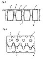
- the welded surface produced by forming recessed ribs from the front surface wall and the rear surface wall and welding the top end parts with each other in the blow molding process is formed by pressuring a parison in a molten state by a mold, the resin in the molten state is pushed out to the outer circumference of the bonding part so as to generate puddle as shown in FIG. 11 .
- the marks a', b' denote a recessed rib, c' a bonding part, and d' a resin puddle swelling to the outside of the bonding part c'.
- a notch part is formed or the thickness of the recessed rib becomes uneven so that the shock absorbing performance of the energy absorbing member is lowered, and thus a desired shock absorbing effect cannot be obtained.
- an object of the present invention is to provide an energy absorbing member for a vehicle made of thermoplastics, capable of providing the excellent shock absorbing property, formed integrally by blow molding, having a hollow part, and a plurality of pairs of recessed ribs provided by denting a first wall and a second wall facing with each other, each toward the other side, and with the top end parts bonding with each other, wherein the recessed ribs are formed at a specific height and a specific interlocking rib is formed for integrally linking the a plurality of the recessed ribs, moreover, the pairs of the recessed ribs are formed by denting the first wall and second wall toward the other side with the top end parts thereof provided adjacently, and furthermore, a certain swelling part is formed preliminarily at the bonding part of the recessed ribs according to the parison pressuring operation.
- a hollow energy-absorbing member for use in the passenger compartment of a vehicle, the member being formed by blow molding of thermoplastics and comprising first and second walls defining a hollow space, a plurality of first recessed frusto-conical ribs integrally moulded with the first wall and extending towards the second wall, each first recessed frusto-conical rib being fused at a welded surface with a second recessed frusto-conical rib integrally moulded with the second wall and extending therefrom wherein said first and second frusto-conical recessed ribs are symmetrically disposed about said welded surface, the average distance from the first wall to said welded surface is 15.0 to 45.0 mm and the average distance from the second wall to said welded surface is 15.0 to 45.0 mm, each of said fused pair of frusto-conical recessed ribs being configured to crush for absorbing an impact from inside the vehicle, and wherein the member further comprises an interlocking rib
- Another embodiment of the present invention provides the energy absorbing member for a vehicle wherein the recessed ribs are disposed on a plurality of virtual straight lines 'c', the lines 'c' being oriented at an angle of about approximately 30 to 60° from line 'd', the line 'd' being a line along a row of the fused pairs of recessed ribs, the interlocking ribs being formed along at least one line 'c'.
- Still another embodiment of the present invention provides the energy absorbing member for a vehicle wherein the interlocking ribs are formed such that a total length of all the interlocking ribs is in a range of 10 to 60% with respect to a total length of all the lines 'c'.
- Even another embodiment of the present invention provides the energy absorbing member for a vehicle wherein the interlocking ribs are a recessed groove having the depth of b(mm), and the width of 2.0 to 5.0(mm).
- the energy absorbing member for a vehicle may further comprise a swelling part having the thickness of 0.5 to 6.0(mm) disposed in a part of the welded surface of the recessed rib end.
- the swelling part may be formed in a hollow shape.
- the swelling part may have a stepwise part projecting having the height of 0.5 to 1.5(mm) from the welded surface.
- Even still another embodiment of the present invention provides the energy absorbing member for a vehicle further comprising at least one unfused pair of recessed ribs having an interval of 5.0 to 18.0(mm) on average disposed between said first and second recessed rib ends.
- An even still further embodiment of the present invention provides the energy absorbing member for a vehicle wherein the fused pairs of recessed ribs comprise 50 to 80% of a total number of a sum of said fused and unfused pairs of recessed ribs.
- a still yet another embodiment of the present invention provides the energy absorbing member for a vehicle wherein the first unfused recessed rib end has a surface chosen from the group of surfaces consisting of a concave surface and a convex surface and said second unfused recessed rib end has a surface of the group not chosen by said first recessed rib.
- a still further embodiment of the present invention provides the energy absorbing member for a vehicle, wherein the recessed ribs having the fused recessed rib ends being integrally fused to the second wall at a welded surface further comprising a hollow swelling part having 0.5 to 6.0 mm thickness is formed in a part of the welded surface.
- Still another embodiment of the present invention provides the energy absorbing member for a vehicle further comprising at least one unfused recessed rib comprising an unfused recessed rib end, and an interval of 5.0 to 18.0 mm on average disposed between the unfused recessed rib end and the second wall.
- a still further embodiment of the present invention provides the energy absorbing member for a vehicle, wherein the fused recessed ribs comprise 50 to 80% of a total number comprising the sum of the fused and unfused recessed ribs.
- the reference numeral 1 denotes an energy absorbing member for a vehicle.
- the energy absorbing member for a vehicle 1 comprised of a thermoplastic resin. It is molded integrally by blow molding, and comprises a hollow part 2, and a plurality of recessed ribs 5, 6 formed by denting both a first wall 3 and a second wall 4 facing with each other, with the top end parts of the first and the second recessed ribs 5, 6 contacted with each other so as to provide a welded surface 7.
- the height from the first wall 3 to the welded surface 7 of the first recessed ribs 5 is formed to 15.0 to 45.0 mm
- the height from the second wall 4 to the welded surface 7 of the second recessed ribs 6 is formed to 15.0 to 45.0 mm.
- the energy absorbing member for a vehicle 1 comprises an interlocking rib 8 for integrally linking a plurality of adjacent recessed ribs 5.
- the interlocking rib 8 is formed on a virtual straight lines c.
- the virtual straight lines are positioned with the angle ⁇ formed with respect to the horizontal line d in a range of 30 to 60°.
- the ratio of the adjacent recessed ribs 5 formed on the virtual straight line with the interlocking ribs 8 formed is 10% to 60%.
- the depth of interlocking ribs 8 is formed in a range of 3.0 ⁇ b ⁇ ⁇ (a/0.5) where "a” is the thickness (mm) of the energy absorbing member 1, and “b” is the depth (mm) of the interlocking ribs.
- the interlocking ribs 8 are a recessed groove having the depth "b" of 3.0 to 15.0 mm, and the width of 2.0 to 5.0mm.
- the interlocking ribs 8 need to have the depth "b" (mm) thereof in a range of 3.0 ⁇ b ⁇ ⁇ (a/0.5) with respect to the thickness a of the main body.
- they are a recessed groove having the depth of 3.0 to 15.0 mm, and the width of 2.0 to 5.0 mm.
- the interlocking ribs 8 are formed such that the total length of all the interlocking ribs is in a range of 10 to 60% with respect to the total length of all the segments virtual lines on both walls from edge to edge. In particular, it is preferable that they are formed only in one of the first wall 3 and the second wall 4, with the ratio of 25%.
- the interlocking ribs 8 are disposed only in the first wall 3, out of the 38 recessed ribs 5, 6 formed in the first wall 3 and the second wall 4 on the virtual straight line c, with the virtual straight line disposed in a range of 30 to 60° of the angle ⁇ with respect to the horizontal line d so as to link the adjacent first recessed ribs 5 with each other only in one inclination direction for 50% of those on the virtual lines. That is, out of the 56 interlocking ribs formable by the calculation, 14 interlocking ribs are formed such that the interlocking ribs 8 are formed by a 25% ratio of the total of the first and second recessed ribs 5, 6 formed on the virtual straight lines. According to an energy absorbing member shown in FIG. 6 , by the same calculation, the interlocking ribs are formed by a 14.3% ratio.
- the depth b of the interlocking ribs 8 is less than 3 mm, the strength needed for constantly maintaining the posture of the recessed ribs 5 is insufficient so as to generate sideways toppling. Moreover, in the case the depth b of the interlocking ribs 8 is larger than the value of the square root of the two times of the thickness a of the energy absorbing member for a vehicle 1, the interlocking ribs 8 are contacted with the facing wall before providing full performance in the process of crushing the first and second recessed ribs 5, 6 at the time of collision so that the desired energy absorbing performance cannot be obtained.
- the interlocking ribs 8 for linking a plurality of the recessed ribs 5 is open or closed such as illustrated in the embodiment shown in FIGS. 7 and 8 .
- the closed interlocking rib 8 so-called inner rib, is formed hidden inside the hollow part 2.
- the inner rib is produced by temporarily forming a groove-like rib from the first wall 3 toward the hollow part 2 direction at the time of blow molding, and integrating into a plate-like rib by the blow pressure.
- the desired energy absorbing performance can be obtained by accordingly providing the interlocking rib 8 as the inner rib.
- FIGS. 9 to 11 A cross-sectional enlarged view of a pair of the recessed ribs is shown in FIGS. 9 to 11 .
- a swelling part 9 is formed integrally, with a hollow part 10 formed in the swelling part 9.
- the swelling part 9 formed on the welded surface 7 of the first and second recessed ribs 5, 6 may be formed as a stepwise fashion 17 with both end parts of the welded surface 7 projecting as shown in FIG. 10 .
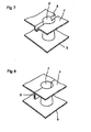
- FIGS. 17 and 18 show a blow molding step for forming the swelling part 9.
- the reference numerals 11, 11 denote a pair of split mold halves, 12, 12 denote cavities, and 13, 13 denote recessed rib forming parts.
- One of the recessed rib forming parts, 13, 13 has a swelling part forming member 14.
- the reference numeral 15 denotes a parison, and 16 an extrusion head.
- the parison 15 As shown in FIG. 17 , by disposing the parison 15 between the pair of the split mold halves 11, 11, closing the mold as shown in FIG. 18 , and blowing a pressurized fluid into the parison 15 for blow molding, the pressed resin flows into the swelling part forming part 14 so as to form the swelling part 9 on the welded surface 7 to be formed by being pressed by the top end surfaces of the recessed rib forming parts 13, 13.
- the waste of the resin to the outer circumference of the welded surface 7 can be prevented according to the influx to the swelling part forming part 14 of the flowing resin pressed by the top end surfaces of the recessed rib forming parts 13, 13, the resin puddle is not generated on the outer circumference of the welded surface 7 so that the thickness irregularity is not generated in the welded surface 7 as well.
- the stepwise parts 17 shown in FIG. 10 can be formed.
- the swelling part 9 projecting stepwise from the welded surface toward the first wall 3 or the second wall 4, with the height thereof in a range of 0.5 to 6.0 mm in the recessed rib 20 axis direction, generation of the resin puddle on the outer circumference of the bonding part can be prevented preferably. Furthermore, by forming the hollow part 10 in the swelling part 9, the thickness of the welded surface 7 can be formed evenly so that an energy absorbing member having the stable energy absorbing property can be formed.
- the energy absorbing member for a vehicle 1 comprises at least one pair of recessed ribs 20 having a welded surface 7 with the top end parts of the first recessed rib 5 and second side rib 6 welded and integrated, and at least one pair of recessed ribs 19 having an interval 18 of 5.0 to 18.0 mm on average with the top end parts of the first recessed rib and the second recessed rib adjacent with each other.
- the recessed ribs 20 having the welded surface 7, the fused ribs are about approximately 50 to 80% with respect to the total number of the recessed ribs.
- some ribs are configured such that the rib from the first wall is separated from its corresponding rib from the second wall by an interval. Such a configuration generally occurs in about approximately 50 to 20% of the ribs in a component.
- the facing interval of the top end parts of the recessed ribs 19 having the interval with the top end parts provided adjacently is preferably 5.0 to 18.0 mm on average.
- one of the pair of the recessed ribs 19 having the interval 18 with the top end parts provided adjacently has the top end part formed as a concave surface part 21, and the other one has the top end part formed as a convex surface part 22, respectively.
- the top end parts by forming the top end parts accordingly, in the state with the recessed ribs 5, 6 deformed by receiving the impact so as to have the top end parts thereof contacted with each other, displacement with each other can be prevented so that the energy absorbing property of the energy absorbing member for a vehicle 1 can further be improved.
- the concave and convex surfaces of the recessed ribs 5, 6 may be provided in any mating fashion.
- the energy absorbing member for a vehicle 1 according to the invention is blow molded as shown in FIGS. 15 and 16 .
- the reference numerals 11, 11 are a pair of split mold halves.
- the split mold halves 11, 11 are provided with recessed rib forming parts 13, 13 for forming the recessed ribs 5, 6.
- the reference numeral 15 denotes a parison, and 16 an extrusion head.
- thermoplastic resin for providing the energy absorbing member for a vehicle 1 according to the invention a resin having large mechanical strength and high degree of rigidity can be used.
- a resin having large mechanical strength and high degree of rigidity examples thereof include a polyolefin resin such as a high density polyethylene resin and a polypropylene resin, a styrene resin such as a polystyrene resin, an acrylonitrile-butadiene-styrene copolymer (ABS resin), an acrylonitrile-styrene resin (AS resin) and an acrylonitrile-acrylic rubber-styrene copolymer (AAS resin), a polyester resin such as a polyethylene terephthalate, a polycarbonate resin, a polyamide resin, a polyphenylene ether resin (PPO resin), and a blended composite thereof.
- a polyolefin resin such as a high density polyethylene resin and a polypropylene resin
- ABS resin acrylon
- the energy absorbing member for a vehicle 1 according to the invention is provided inside a vehicle structural member such as a door of, a door trim, a body side panel, a roof panel, a pillar, or the like.
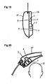
- FIG. 19 shows an embodiment of providing the energy absorbing member for a vehicle 1 according to the invention inside a door trim 24 of a door 23
- FIG. 20 shows an embodiment of providing the same inside a rear pillar 25 of an automobile.
- the mark A denotes the head of a passenger.
- FIG. 21 illustrates an energy absorbing member for a vehicle 1 according to one embodiment of the present invention which comprises the recessed rib 5 provided by denting the first wall 3 toward the facing second wall 4.
- FIG. 22 shows an enlarged cross-sectional view taken on the line C-C of FIG. 21 , which illustrates an energy absorbing member 1 according to one embodiment of the present invention.
- the impact absorbing member for a vehicle according to the invention can be used preferably as a member for absorbing the impact of the collision, or the like by being disposed inside a vehicle structural member such as a door, a door trim, a body side panel, a roof panel, a pillar, a seat, and an instrument panel of an automobile, or the like.
- a vehicle structural member such as a door, a door trim, a body side panel, a roof panel, a pillar, a seat, and an instrument panel of an automobile, or the like.
Claims (6)
- Hohles Stossdämpfungselement (1) zur Verwendung im Insassenraum eines Fahrzeugs, wobei das Element durch Blasformen eines Thermoplasten geformt ist und eine erste (3) und eine zweite Wand (4) umfasst, welche einen Hohlraum (2) begrenzen, eine Vielzahl erster ausgesparter kegelstumpfförmiger Rippen (5), die integral mit der ersten Wand (3) ausgebildet sind und sich in Richtung der zweiten Wand (4) erstrecken, wobei jede erste ausgesparte kegelstumpfförmige Rippe (5) an einer Schweißfläche (7) mit einer zweiten ausgesparten kegelstumpfförmigen Rippe (6) verschweißt ist, die integral mit der zweiten Wand (4) ausgebildet ist und sich von dieser erstreckt, wobei die ersten (5) und zweiten (6) kegelstumpfförmigen ausgesparten Rippen symmetrisch um die Schweißfläche (7) angeordnet sind, der durchschnittliche Abstand von der ersten Wand (3) zu der Schweißfläche (7) 15,0 bis 45,0 mm beträgt und der durchschnittliche Abstand von der zweiten Wand (4) zu der Schweißfläche (7) 15,0 bis 45,0 mm beträgt, jedes der verschweißten Paare kegelstumpfförmiger ausgesparter Rippen (5, 6) eindrückbar ist, um einem Stoß von innerhalb des Fahrzeugs aufzunehmen, und wobei das Element (1) weiterhin eine Verbindungsrippe (8) an der ersten Wand (3) oder der zweiten Wand (4) aufweist, die integral mit zumindest zwei benachbarten der ersten ausgesparten kegelstumpfförmigen Rippen (5) oder der zweiten ausgesparten kegelstumpfförmigen Rippen (6) gekoppelt ist;
dadurch gekennzeichnet, dass die Verbindungsrippe (8) eine Tiefe von b mm innerhalb eines Bereichs von 3,0 ≤ b ≤ √(a/0,5) aufweist, wobei a mm der Abstand zwischen der ersten (3) und zweiten Wand (4) ist. - Hohles Stossdämpfungselement (1) nach Anspruch 1, bei dem die ausgesparten kegelstumpfförmigen Rippen (5, 6) auf einer Vielzahl virtueller gerader Linien (c) angeordnet sind, wobei die virtuelle gerade Linie mit einem Winkel von etwa 30° bis 60° zu einer horizontalen Linie, die eine Linie entlang einer Reihe der verschweißten Paare kegelstumpfförmiger ausgesparter Rippen (5, 6) ist, angestellt ist, wobei die Verbindungsrippen entlang zumindest einer virtuellen geraden Linie (c) geformt sind.
- Hohles Stossdämpfungselement (1) nach Anspruch 2, bei dem die Verbindungsrippen (8) so geformt sind, dass die gesamte Länge aller Verbindungsrippen (8) in einem Bereich von 10 bis 60% der gesamten Länge aller virtuellen Linien liegt.
- Hohles Stossdämpfungselement (1) nach Anspruch 1, 2 oder 3, bei dem die Verbindungsrippen (8) eine ausgesparte Nut mit einer Tiefe von b mm und einer Breite von 2,0 bis 5,0 mm sind.
- Fahrzeug, das in seinem Insassenraum ein hohles Stossdämpfungselement nach einem der vorgenannten Ansprüche aufweist, wobei das Element positioniert ist, um einen Stoß zwischen der Hüfte oder Brust eines Insassen und einer Fahrzeugtürverkleidung aufzunehmen.
- Fahrzeug, das in seinem Insassenraum ein hohles Stossdämpfungselement nach einem der Ansprüche 1 bis 4 aufweist, wobei das Element positioniert ist, um einen Stoß zwischen dem Kopf eines Insassen und einer Dachverkleidung oder einem Dachstützholm aufzunehmen.
Applications Claiming Priority (29)
| Application Number | Priority Date | Filing Date | Title |
|---|---|---|---|
| JP2002319161A JP2004149075A (ja) | 2002-10-31 | 2002-10-31 | 車両用衝撃吸収体 |
| JP2002319163 | 2002-10-31 | ||
| JP2002319160 | 2002-10-31 | ||
| JP2002319163A JP4181630B2 (ja) | 2002-10-31 | 2002-10-31 | 車両用衝撃吸収体 |
| JP2002319161 | 2002-10-31 | ||
| JP2002319162A JP4229676B2 (ja) | 2002-10-31 | 2002-10-31 | 車両用衝撃吸収体 |
| JP2002319160A JP2004149074A (ja) | 2002-10-31 | 2002-10-31 | 車両用衝撃吸収体 |
| JP2002319162 | 2002-10-31 | ||
| JP2003025254A JP2004232827A (ja) | 2003-01-31 | 2003-01-31 | 車両用衝撃吸収体 |
| JP2003025257 | 2003-01-31 | ||
| JP2003025255 | 2003-01-31 | ||
| JP2003025257A JP2004231144A (ja) | 2003-01-31 | 2003-01-31 | 車両用衝撃吸収体 |
| JP2003025258 | 2003-01-31 | ||
| JP2003025256 | 2003-01-31 | ||
| JP2003025254 | 2003-01-31 | ||
| JP2003025256A JP2004231143A (ja) | 2003-01-31 | 2003-01-31 | 車両用衝撃吸収体 |
| JP2003025258A JP2004231145A (ja) | 2003-01-31 | 2003-01-31 | 車両用衝撃吸収体 |
| JP2003025255A JP4220795B2 (ja) | 2003-01-31 | 2003-01-31 | 車両用衝撃吸収体 |
| JP2003054857 | 2003-02-28 | ||
| JP2003054858A JP2004262343A (ja) | 2003-02-28 | 2003-02-28 | 車両用衝撃吸収体 |
| JP2003054857 | 2003-02-28 | ||
| JP2003054858 | 2003-02-28 | ||
| JP2003054856A JP4181631B2 (ja) | 2003-02-28 | 2003-02-28 | 車両用衝撃吸収体 |
| JP2003054856 | 2003-02-28 | ||
| JP2003097349 | 2003-03-31 | ||
| JP2003097349A JP4271476B2 (ja) | 2003-02-28 | 2003-03-31 | 車両用衝撃吸収体 |
| JP2003135249 | 2003-05-14 | ||
| JP2003135249 | 2003-05-14 | ||
| PCT/JP2003/010011 WO2004040161A1 (ja) | 2002-10-31 | 2003-08-06 | 車両用衝撃吸収体 |
Publications (3)
| Publication Number | Publication Date |
|---|---|
| EP1557582A1 EP1557582A1 (de) | 2005-07-27 |
| EP1557582A4 EP1557582A4 (de) | 2006-05-24 |
| EP1557582B1 true EP1557582B1 (de) | 2012-02-29 |
Family
ID=32234569
Family Applications (2)
| Application Number | Title | Priority Date | Filing Date |
|---|---|---|---|
| EP03809842A Expired - Lifetime EP1557583B1 (de) | 2002-10-31 | 2003-08-06 | Stossdämpfer für fahrzeug |
| EP03809840A Expired - Lifetime EP1557582B1 (de) | 2002-10-31 | 2003-08-06 | Stossdämpfungskörper für fahrzeuge |
Family Applications Before (1)
| Application Number | Title | Priority Date | Filing Date |
|---|---|---|---|
| EP03809842A Expired - Lifetime EP1557583B1 (de) | 2002-10-31 | 2003-08-06 | Stossdämpfer für fahrzeug |
Country Status (6)
| Country | Link |
|---|---|
| US (6) | US7111713B2 (de) |
| EP (2) | EP1557583B1 (de) |
| AT (2) | ATE475031T1 (de) |
| AU (3) | AU2003254828A1 (de) |
| CA (2) | CA2504485C (de) |
| WO (3) | WO2004040161A1 (de) |
Families Citing this family (44)
| Publication number | Priority date | Publication date | Assignee | Title |
|---|---|---|---|---|
| WO2004040161A1 (ja) * | 2002-10-31 | 2004-05-13 | Kyoraku Co., Ltd. | 車両用衝撃吸収体 |
| JP4280153B2 (ja) * | 2003-11-28 | 2009-06-17 | キョーラク株式会社 | 車両用衝撃吸収体 |
| US7338038B2 (en) * | 2004-03-12 | 2008-03-04 | Dow Global Technologies, Inc. | Impact absorption structure |
| EP1607272B1 (de) * | 2004-06-16 | 2008-08-13 | Jacob Composite GmbH | Bauteil zur Energieaufnahme bei einem Aufprall |
| JP4531468B2 (ja) * | 2004-07-14 | 2010-08-25 | 小島プレス工業株式会社 | 車両用衝撃吸収構造体及びその取付構造 |
| JP4598468B2 (ja) * | 2004-09-30 | 2010-12-15 | キョーラク株式会社 | 車両用衝撃吸収体 |
| US7168880B2 (en) | 2004-11-17 | 2007-01-30 | Battelle Memorial Institute | Impact attenuator system |
| FR2883348B1 (fr) * | 2005-03-21 | 2007-04-27 | Faurecia Interieur Ind Snc | Piece injectee, ensemble d'absorption d'energie a entretoise et procede de fabrication d'un tel ensemble |
| US20060257332A1 (en) * | 2005-05-13 | 2006-11-16 | Pierro Francesco D | Anticaries compositions containing phaseolamin |
| US7866540B2 (en) * | 2005-05-24 | 2011-01-11 | Cox Leonard R | Shock and vibration absorbing device and method |
| US7625036B2 (en) * | 2006-04-04 | 2009-12-01 | Oakwood Energy Management, Inc. | Multi-sectional modular energy absorber and method for configuring same |
| JP4227153B2 (ja) * | 2006-06-20 | 2009-02-18 | 小島プレス工業株式会社 | 車両用衝撃吸収構造体 |
| JP5076790B2 (ja) * | 2006-12-20 | 2012-11-21 | パナソニック株式会社 | 衝撃保護装置 |
| JP5357004B2 (ja) * | 2007-02-28 | 2013-12-04 | キョーラク株式会社 | 車両用衝撃吸収体 |
| US8262051B2 (en) * | 2007-08-23 | 2012-09-11 | Raytheon Company | Z-leg shock isolator |
| CA2721238C (en) * | 2008-03-17 | 2015-10-06 | Battelle Memorial Institute | Rebound control material |
| US7874611B2 (en) * | 2008-04-03 | 2011-01-25 | GM Global Technology Operations LLC | Scalable two-piece reinforcement and method for producing same |
| US20100207443A1 (en) * | 2009-02-19 | 2010-08-19 | Faurecia Automotive Seating, Inc. | Vehicle seat cushion with inflatable air bladder |
| US9644699B2 (en) * | 2009-03-30 | 2017-05-09 | Oakwood Energy Management, Inc. | Energy absorber with anti-BSR accessory |
| AU2014277803A1 (en) * | 2009-04-07 | 2015-02-05 | Valmont Highway Technology Limited | Energy Absorption Device |
| EP2417299A4 (de) * | 2009-04-07 | 2015-03-04 | Valmont Highway Technology Ltd | Energieabsorbierende vorrichtung |
| FR2949250B1 (fr) * | 2009-08-24 | 2012-01-06 | Aliaxis R & D Sas | Pont amortissant |
| CN102712275B (zh) | 2009-12-02 | 2015-11-25 | 佛吉亚汽车座椅有限责任公司 | 具有可充气支撑装置的车辆座椅靠垫 |
| WO2011149049A1 (ja) | 2010-05-28 | 2011-12-01 | キョーラク株式会社 | 衝撃吸収体及び衝撃吸収体の製造方法 |
| JP5700210B2 (ja) * | 2011-03-15 | 2015-04-15 | キョーラク株式会社 | 車両用衝撃エネルギー吸収体およびその成形方法 |
| CN103562015B (zh) * | 2011-04-05 | 2016-08-24 | 京洛株式会社 | 冲击吸收体 |
| CN104334911B (zh) * | 2012-04-05 | 2019-04-30 | 京洛株式会社 | 膝垫构件 |
| WO2013187490A1 (ja) | 2012-06-14 | 2013-12-19 | 株式会社ニフコ | 荷重伝達部材及び自動車用ドアへの荷重伝達部材取付構造 |
| JP5966666B2 (ja) * | 2012-06-26 | 2016-08-10 | キョーラク株式会社 | 衝撃エネルギー吸収体 |
| US9403498B2 (en) | 2013-03-20 | 2016-08-02 | Shiloh Industries, Inc. | Energy absorbing assembly for vehicle |
| US9522646B2 (en) * | 2013-03-28 | 2016-12-20 | Kyoraku Co., Ltd. | Knee bolster |
| DE102013105155B4 (de) * | 2013-05-21 | 2024-04-18 | Dr. Ing. H.C. F. Porsche Aktiengesellschaft | Deformationselement |
| JP6390063B2 (ja) * | 2013-09-26 | 2018-09-19 | キョーラク株式会社 | 衝撃吸収体 |
| US9415708B2 (en) | 2014-02-18 | 2016-08-16 | Oakwood Energy Management, Inc. | Conformable energy absorber |
| JP6156291B2 (ja) * | 2014-09-01 | 2017-07-05 | トヨタ自動車株式会社 | 車両用ドア構造 |
| JP6477060B2 (ja) * | 2015-03-11 | 2019-03-06 | キョーラク株式会社 | ニーボルスター |
| US10647283B2 (en) * | 2015-11-27 | 2020-05-12 | Kyoraku Co., Ltd. | Shock absorber |
| US9994137B2 (en) * | 2016-02-16 | 2018-06-12 | Ford Global Technologies, Llc | Deformable armrest having a patterned array of channels |
| US10788091B2 (en) | 2017-08-22 | 2020-09-29 | Oakwood Energy Management, Inc. | Mass-optimized force attenuation system and method |
| US10286821B1 (en) | 2017-10-24 | 2019-05-14 | Ford Global Technologies, Llc | Armrest core, armrest incorporating that armrest core and method of manufacturing that armrest assembly |
| US11585102B2 (en) | 2018-11-07 | 2023-02-21 | Viconic Sporting Llc | Load distribution and absorption underpayment system |
| US10982451B2 (en) | 2018-11-07 | 2021-04-20 | Viconic Sporting Llc | Progressive stage load distribution and absorption underlayment system |
| DE112019006085T5 (de) * | 2018-12-06 | 2021-08-19 | Gentherm Incorporated | Nachgiebiges plenum mit versteifungsmerkmalen |
| US11318869B2 (en) * | 2018-12-06 | 2022-05-03 | Gentherm Incorporated | Single piece plenum |
Family Cites Families (51)
| Publication number | Priority date | Publication date | Assignee | Title |
|---|---|---|---|---|
| US2434641A (en) * | 1946-02-20 | 1948-01-20 | Henry L Burns | Resilient seat cushion |
| IT963692B (it) * | 1972-08-03 | 1974-01-21 | Montedison Spa | Poliesteri antiurto |
| US3933387A (en) * | 1975-03-10 | 1976-01-20 | General Motors Corporation | Thermoformed plastic energy absorber for vehicles |
| US4375108A (en) * | 1981-01-28 | 1983-03-01 | The Regents Of The University Of Michigan | Energy-absorbing insert for protective headgear |
| JPH0649480Y2 (ja) * | 1985-01-12 | 1994-12-14 | 池田物産株式会社 | 合成樹脂製の中空板体 |
| JPS6271425U (de) * | 1985-10-24 | 1987-05-07 | ||
| US4901486A (en) * | 1987-03-06 | 1990-02-20 | Kajima Corporation | Elasto-plastic damper |
| US4894352A (en) * | 1988-10-26 | 1990-01-16 | Texas Instruments Inc. | Deposition of silicon-containing films using organosilicon compounds and nitrogen trifluoride |
| DE68907880T2 (de) * | 1988-12-24 | 1993-11-04 | Minoru Sangyo | Stossstange aus kunststoff. |
| US4895352A (en) * | 1989-01-09 | 1990-01-23 | Simmons Company | Mattress or cushion spring array |
| US4925224A (en) * | 1989-03-06 | 1990-05-15 | Romeo-Rim, Inc. | Energy absorbing vehicle bumper |
| JPH031925A (ja) * | 1989-05-30 | 1991-01-08 | Kyoraku Co Ltd | リブ付き中空パネルおよびその製造方法 |
| JP2777832B2 (ja) * | 1989-12-28 | 1998-07-23 | 東海興業株式会社 | 車輌用モールデイングおよびその製造方法 |
| JPH04293959A (ja) * | 1991-03-25 | 1992-10-19 | Nippon Petrochem Co Ltd | 熱可塑性樹脂組成物 |
| US5367016A (en) * | 1991-11-28 | 1994-11-22 | Kanegafuchi Chemical Industry Co., Ltd. | Reinforced resin composition |
| US5251414A (en) * | 1992-03-16 | 1993-10-12 | Duke Darryl A | Energy absorbing composite and reinforcing core |
| JP3363534B2 (ja) * | 1993-07-23 | 2003-01-08 | 株式会社イノアックコーポレーション | 自動車用緩衝内装材およびその製法 |
| JP3052766B2 (ja) * | 1994-02-22 | 2000-06-19 | トヨタ自動車株式会社 | 自動車の内装材による衝撃エネルギ吸収構造 |
| US5934730A (en) * | 1994-07-01 | 1999-08-10 | Nissan Motor Co., Ltd | Energy absorbing door panel |
| US5636866A (en) * | 1994-09-21 | 1997-06-10 | Kojima Press Industry Co., Ltd. | Shock absorbing structure for motor vehicle |
| WO1996016564A1 (en) * | 1994-12-02 | 1996-06-06 | Nike International Ltd. | Cushioning device for a footwear sole and method for making the same |
| JP2945859B2 (ja) * | 1995-10-23 | 1999-09-06 | 株式会社イノアックコーポレーション | 車両側部内装部材 |
| JP3186563B2 (ja) * | 1996-01-31 | 2001-07-11 | トヨタ自動車株式会社 | 衝撃エネルギー吸収部材 |
| US6085878A (en) * | 1996-12-13 | 2000-07-11 | Toyo Boseki Kabushiki Kaisha | Impact absorber made of resin |
| WO1998036943A1 (en) * | 1997-02-21 | 1998-08-27 | Lear Corporation | Structural headliner |
| JP3313999B2 (ja) * | 1997-03-13 | 2002-08-12 | キョーラク株式会社 | 車両用衝撃吸収体 |
| JPH1182587A (ja) * | 1997-09-04 | 1999-03-26 | Nippon Plast Co Ltd | 衝撃緩衝部材 |
| US6551450B1 (en) * | 1997-10-10 | 2003-04-22 | D2Rm Corp. | Unique air and sonic massaging apparatus |
| US6029962A (en) * | 1997-10-24 | 2000-02-29 | Retama Technology Corporation | Shock absorbing component and construction method |
| US6199942B1 (en) * | 1998-02-04 | 2001-03-13 | Oakwood Energy Management, Inc. | Modular energy absorbing assembly |
| US6182732B1 (en) * | 1998-03-03 | 2001-02-06 | Nordson Corporation | Apparatus for the manufacture of nonwoven webs and laminates including means to move the spinning assembly |
| US6000738A (en) * | 1998-03-13 | 1999-12-14 | Chrysler Corporation | Force-absorbing vehicle bumper |
| US6082792A (en) * | 1998-05-07 | 2000-07-04 | General Electric Company | Vehicle bumper |
| JPH11348699A (ja) * | 1998-06-12 | 1999-12-21 | Toyota Motor Corp | 車両用内装部品の衝撃吸収構造 |
| US6086145A (en) * | 1998-07-16 | 2000-07-11 | Textron Automotive Company Inc. | Blow molded headliner |
| JP4383529B2 (ja) * | 1998-09-30 | 2009-12-16 | キョーラク株式会社 | 車両における衝撃吸收構造 |
| JP2000170814A (ja) * | 1998-09-30 | 2000-06-23 | Mazda Motor Corp | 衝撃吸収構造 |
| JP2000177518A (ja) * | 1998-12-16 | 2000-06-27 | Kasai Kogyo Co Ltd | 車両用側面衝突対応パッド構造 |
| JP2001030754A (ja) * | 1999-07-15 | 2001-02-06 | Idemitsu Petrochem Co Ltd | 自動車用ドア内側部材 |
| US6234526B1 (en) | 1999-09-27 | 2001-05-22 | Daimlerchrysler Corporation | Head impact protection using fluid viscosity |
| JP4427849B2 (ja) * | 1999-11-25 | 2010-03-10 | 株式会社カネカ | 耐衝撃性に優れた車両用内装材 |
| US6385864B1 (en) * | 2000-03-16 | 2002-05-14 | Nike, Inc. | Footwear bladder with controlled flex tensile member |
| US6406079B2 (en) * | 2000-07-14 | 2002-06-18 | Kyoraku Co., Ltd. | Automobile bumper core |
| JP4584444B2 (ja) * | 2000-12-19 | 2010-11-24 | キョーラク株式会社 | 自動車の衝撃吸収部材 |
| JP2002120681A (ja) * | 2000-08-07 | 2002-04-23 | Kanegafuchi Chem Ind Co Ltd | 車両用内装部材 |
| FR2815100B1 (fr) * | 2000-10-09 | 2003-04-18 | Sai Automotive Allibert Ind | Dispositif d'absorption d'energie lors d'un choc, et portiere de vehicule automobile comprenant un tel dispositif |
| JP2002201322A (ja) | 2000-12-28 | 2002-07-19 | Idemitsu Petrochem Co Ltd | ポリプロピレン樹脂組成物 |
| US6588557B2 (en) | 2001-04-04 | 2003-07-08 | Daimlerchrysler Corporation | Blow molded (HIC) formation with energy buffers |
| JP4360050B2 (ja) | 2001-06-11 | 2009-11-11 | 三菱自動車工業株式会社 | 衝撃吸収装置 |
| WO2004040161A1 (ja) * | 2002-10-31 | 2004-05-13 | Kyoraku Co., Ltd. | 車両用衝撃吸収体 |
| US6698819B1 (en) | 2002-12-10 | 2004-03-02 | Lear Corporation | Pneumatic pressure molded impact countermeasure |
-
2003
- 2003-08-06 WO PCT/JP2003/010011 patent/WO2004040161A1/ja active Application Filing
- 2003-08-06 AU AU2003254828A patent/AU2003254828A1/en not_active Abandoned
- 2003-08-06 AU AU2003257809A patent/AU2003257809A1/en not_active Abandoned
- 2003-08-06 AT AT03809842T patent/ATE475031T1/de not_active IP Right Cessation
- 2003-08-06 WO PCT/JP2003/010012 patent/WO2004040162A1/ja active Application Filing
- 2003-08-06 EP EP03809842A patent/EP1557583B1/de not_active Expired - Lifetime
- 2003-08-06 WO PCT/JP2003/010013 patent/WO2004040163A1/ja active Application Filing
- 2003-08-06 CA CA2504485A patent/CA2504485C/en not_active Expired - Lifetime
- 2003-08-06 CA CA2504490A patent/CA2504490C/en not_active Expired - Fee Related
- 2003-08-06 EP EP03809840A patent/EP1557582B1/de not_active Expired - Lifetime
- 2003-08-06 AU AU2003254829A patent/AU2003254829A1/en not_active Abandoned
- 2003-08-06 AT AT03809840T patent/ATE547647T1/de active
- 2003-10-31 US US10/698,706 patent/US7111713B2/en not_active Expired - Lifetime
- 2003-10-31 US US10/698,537 patent/US20040129518A1/en not_active Abandoned
- 2003-10-31 US US10/698,314 patent/US7143876B2/en not_active Expired - Lifetime
-
2005
- 2005-05-17 US US11/130,616 patent/US7306080B2/en active Active
- 2005-11-28 US US11/287,984 patent/US7178647B2/en not_active Expired - Lifetime
-
2006
- 2006-05-08 US US11/430,287 patent/US7306081B2/en not_active Expired - Lifetime
Also Published As
| Publication number | Publication date |
|---|---|
| US20040129518A1 (en) | 2004-07-08 |
| ATE475031T1 (de) | 2010-08-15 |
| US20060076202A1 (en) | 2006-04-13 |
| US20040124572A1 (en) | 2004-07-01 |
| WO2004040162A1 (ja) | 2004-05-13 |
| EP1557583A4 (de) | 2006-07-12 |
| US20050230204A1 (en) | 2005-10-20 |
| ATE547647T1 (de) | 2012-03-15 |
| US20060220290A1 (en) | 2006-10-05 |
| US7143876B2 (en) | 2006-12-05 |
| US7306081B2 (en) | 2007-12-11 |
| US7111713B2 (en) | 2006-09-26 |
| CA2504490A1 (en) | 2004-05-13 |
| WO2004040163A1 (ja) | 2004-05-13 |
| AU2003254829A1 (en) | 2004-05-25 |
| AU2003257809A1 (en) | 2004-05-25 |
| US7178647B2 (en) | 2007-02-20 |
| EP1557582A1 (de) | 2005-07-27 |
| AU2003254828A1 (en) | 2004-05-25 |
| EP1557582A4 (de) | 2006-05-24 |
| EP1557583A1 (de) | 2005-07-27 |
| CA2504485A1 (en) | 2004-05-13 |
| EP1557583B1 (de) | 2010-07-21 |
| CA2504490C (en) | 2011-05-03 |
| US7306080B2 (en) | 2007-12-11 |
| WO2004040161A1 (ja) | 2004-05-13 |
| US20040195064A1 (en) | 2004-10-07 |
| CA2504485C (en) | 2011-03-22 |
Similar Documents
| Publication | Publication Date | Title |
|---|---|---|
| EP1557582B1 (de) | Stossdämpfungskörper für fahrzeuge | |
| US7618082B2 (en) | Vehicle shock absorber | |
| US8016344B2 (en) | Vehicle impact absorbing member | |
| EP1623880B1 (de) | Stossdämpfer für ein auto | |
| EP1172260A2 (de) | Fahrzeugstossstange | |
| US8443950B2 (en) | Shock absorber for vehicle | |
| US5658027A (en) | Blow molded vehicle bumper system in method | |
| JP4584444B2 (ja) | 自動車の衝撃吸収部材 | |
| CN100398361C (zh) | 车辆用冲击吸收体 | |
| JP4559200B2 (ja) | 衝撃吸収体 | |
| JP4271476B2 (ja) | 車両用衝撃吸収体 | |
| JP4206127B2 (ja) | 車両用衝撃吸収体 | |
| JP4772847B2 (ja) | 車両用衝撃吸収体 | |
| JP4662331B2 (ja) | 車両用衝撃吸収体 | |
| JP3578818B2 (ja) | 自動車用ドアトリム | |
| JP4229676B2 (ja) | 車両用衝撃吸収体 | |
| JP2005132303A (ja) | 車両用衝撃吸収体 | |
| JP2004262343A (ja) | 車両用衝撃吸収体 | |
| JP2004231143A (ja) | 車両用衝撃吸収体 |
Legal Events
| Date | Code | Title | Description |
|---|---|---|---|
| PUAI | Public reference made under article 153(3) epc to a published international application that has entered the european phase |
Free format text: ORIGINAL CODE: 0009012 |
|
| 17P | Request for examination filed |
Effective date: 20050428 |
|
| AK | Designated contracting states |
Kind code of ref document: A1 Designated state(s): AT BE BG CH CY CZ DE DK EE ES FI FR GB GR HU IE IT LI LU MC NL PT RO SE SI SK TR |
|
| RIC1 | Information provided on ipc code assigned before grant |
Ipc: 7B 29C 49/48 B Ipc: 7B 60R 19/18 B Ipc: 7B 29C 49/04 B Ipc: 7B 60R 21/04 B Ipc: 7F 16F 7/00 A |
|
| A4 | Supplementary search report drawn up and despatched |
Effective date: 20060406 |
|
| 17Q | First examination report despatched |
Effective date: 20060823 |
|
| GRAP | Despatch of communication of intention to grant a patent |
Free format text: ORIGINAL CODE: EPIDOSNIGR1 |
|
| GRAS | Grant fee paid |
Free format text: ORIGINAL CODE: EPIDOSNIGR3 |
|
| GRAA | (expected) grant |
Free format text: ORIGINAL CODE: 0009210 |
|
| AK | Designated contracting states |
Kind code of ref document: B1 Designated state(s): AT BE BG CH CY CZ DE DK EE ES FI FR GB GR HU IE IT LI LU MC NL PT RO SE SI SK TR |
|
| REG | Reference to a national code |
Ref country code: GB Ref legal event code: FG4D Ref country code: CH Ref legal event code: EP |
|
| REG | Reference to a national code |
Ref country code: AT Ref legal event code: REF Ref document number: 547647 Country of ref document: AT Kind code of ref document: T Effective date: 20120315 |
|
| REG | Reference to a national code |
Ref country code: IE Ref legal event code: FG4D |
|
| REG | Reference to a national code |
Ref country code: DE Ref legal event code: R082 Ref document number: 60340168 Country of ref document: DE Representative=s name: BECK & ROESSIG - EUROPEAN PATENT ATTORNEYS, DE |
|
| REG | Reference to a national code |
Ref country code: DE Ref legal event code: R096 Ref document number: 60340168 Country of ref document: DE Effective date: 20120426 |
|
| REG | Reference to a national code |
Ref country code: NL Ref legal event code: VDEP Effective date: 20120229 |
|
| PG25 | Lapsed in a contracting state [announced via postgrant information from national office to epo] |
Ref country code: NL Free format text: LAPSE BECAUSE OF FAILURE TO SUBMIT A TRANSLATION OF THE DESCRIPTION OR TO PAY THE FEE WITHIN THE PRESCRIBED TIME-LIMIT Effective date: 20120229 |
|
| PG25 | Lapsed in a contracting state [announced via postgrant information from national office to epo] |
Ref country code: BE Free format text: LAPSE BECAUSE OF FAILURE TO SUBMIT A TRANSLATION OF THE DESCRIPTION OR TO PAY THE FEE WITHIN THE PRESCRIBED TIME-LIMIT Effective date: 20120229 Ref country code: GR Free format text: LAPSE BECAUSE OF FAILURE TO SUBMIT A TRANSLATION OF THE DESCRIPTION OR TO PAY THE FEE WITHIN THE PRESCRIBED TIME-LIMIT Effective date: 20120530 Ref country code: FI Free format text: LAPSE BECAUSE OF FAILURE TO SUBMIT A TRANSLATION OF THE DESCRIPTION OR TO PAY THE FEE WITHIN THE PRESCRIBED TIME-LIMIT Effective date: 20120229 Ref country code: PT Free format text: LAPSE BECAUSE OF FAILURE TO SUBMIT A TRANSLATION OF THE DESCRIPTION OR TO PAY THE FEE WITHIN THE PRESCRIBED TIME-LIMIT Effective date: 20120629 |
|
| REG | Reference to a national code |
Ref country code: AT Ref legal event code: MK05 Ref document number: 547647 Country of ref document: AT Kind code of ref document: T Effective date: 20120229 |
|
| PG25 | Lapsed in a contracting state [announced via postgrant information from national office to epo] |
Ref country code: CY Free format text: LAPSE BECAUSE OF FAILURE TO SUBMIT A TRANSLATION OF THE DESCRIPTION OR TO PAY THE FEE WITHIN THE PRESCRIBED TIME-LIMIT Effective date: 20120229 |
|
| PG25 | Lapsed in a contracting state [announced via postgrant information from national office to epo] |
Ref country code: CZ Free format text: LAPSE BECAUSE OF FAILURE TO SUBMIT A TRANSLATION OF THE DESCRIPTION OR TO PAY THE FEE WITHIN THE PRESCRIBED TIME-LIMIT Effective date: 20120229 Ref country code: SI Free format text: LAPSE BECAUSE OF FAILURE TO SUBMIT A TRANSLATION OF THE DESCRIPTION OR TO PAY THE FEE WITHIN THE PRESCRIBED TIME-LIMIT Effective date: 20120229 Ref country code: RO Free format text: LAPSE BECAUSE OF FAILURE TO SUBMIT A TRANSLATION OF THE DESCRIPTION OR TO PAY THE FEE WITHIN THE PRESCRIBED TIME-LIMIT Effective date: 20120229 Ref country code: DK Free format text: LAPSE BECAUSE OF FAILURE TO SUBMIT A TRANSLATION OF THE DESCRIPTION OR TO PAY THE FEE WITHIN THE PRESCRIBED TIME-LIMIT Effective date: 20120229 Ref country code: EE Free format text: LAPSE BECAUSE OF FAILURE TO SUBMIT A TRANSLATION OF THE DESCRIPTION OR TO PAY THE FEE WITHIN THE PRESCRIBED TIME-LIMIT Effective date: 20120229 Ref country code: SE Free format text: LAPSE BECAUSE OF FAILURE TO SUBMIT A TRANSLATION OF THE DESCRIPTION OR TO PAY THE FEE WITHIN THE PRESCRIBED TIME-LIMIT Effective date: 20120229 |
|
| PG25 | Lapsed in a contracting state [announced via postgrant information from national office to epo] |
Ref country code: IT Free format text: LAPSE BECAUSE OF FAILURE TO SUBMIT A TRANSLATION OF THE DESCRIPTION OR TO PAY THE FEE WITHIN THE PRESCRIBED TIME-LIMIT Effective date: 20120229 Ref country code: SK Free format text: LAPSE BECAUSE OF FAILURE TO SUBMIT A TRANSLATION OF THE DESCRIPTION OR TO PAY THE FEE WITHIN THE PRESCRIBED TIME-LIMIT Effective date: 20120229 |
|
| PLBE | No opposition filed within time limit |
Free format text: ORIGINAL CODE: 0009261 |
|
| STAA | Information on the status of an ep patent application or granted ep patent |
Free format text: STATUS: NO OPPOSITION FILED WITHIN TIME LIMIT |
|
| PG25 | Lapsed in a contracting state [announced via postgrant information from national office to epo] |
Ref country code: AT Free format text: LAPSE BECAUSE OF FAILURE TO SUBMIT A TRANSLATION OF THE DESCRIPTION OR TO PAY THE FEE WITHIN THE PRESCRIBED TIME-LIMIT Effective date: 20120229 |
|
| 26N | No opposition filed |
Effective date: 20121130 |
|
| REG | Reference to a national code |
Ref country code: DE Ref legal event code: R097 Ref document number: 60340168 Country of ref document: DE Effective date: 20121130 Ref country code: CH Ref legal event code: PL |
|
| PG25 | Lapsed in a contracting state [announced via postgrant information from national office to epo] |
Ref country code: MC Free format text: LAPSE BECAUSE OF NON-PAYMENT OF DUE FEES Effective date: 20120831 |
|
| PG25 | Lapsed in a contracting state [announced via postgrant information from national office to epo] |
Ref country code: CH Free format text: LAPSE BECAUSE OF NON-PAYMENT OF DUE FEES Effective date: 20120831 Ref country code: ES Free format text: LAPSE BECAUSE OF FAILURE TO SUBMIT A TRANSLATION OF THE DESCRIPTION OR TO PAY THE FEE WITHIN THE PRESCRIBED TIME-LIMIT Effective date: 20120609 Ref country code: LI Free format text: LAPSE BECAUSE OF NON-PAYMENT OF DUE FEES Effective date: 20120831 |
|
| REG | Reference to a national code |
Ref country code: IE Ref legal event code: MM4A |
|
| PG25 | Lapsed in a contracting state [announced via postgrant information from national office to epo] |
Ref country code: BG Free format text: LAPSE BECAUSE OF FAILURE TO SUBMIT A TRANSLATION OF THE DESCRIPTION OR TO PAY THE FEE WITHIN THE PRESCRIBED TIME-LIMIT Effective date: 20120529 Ref country code: IE Free format text: LAPSE BECAUSE OF NON-PAYMENT OF DUE FEES Effective date: 20120806 |
|
| PG25 | Lapsed in a contracting state [announced via postgrant information from national office to epo] |
Ref country code: TR Free format text: LAPSE BECAUSE OF FAILURE TO SUBMIT A TRANSLATION OF THE DESCRIPTION OR TO PAY THE FEE WITHIN THE PRESCRIBED TIME-LIMIT Effective date: 20120229 |
|
| PG25 | Lapsed in a contracting state [announced via postgrant information from national office to epo] |
Ref country code: LU Free format text: LAPSE BECAUSE OF NON-PAYMENT OF DUE FEES Effective date: 20120806 |
|
| PG25 | Lapsed in a contracting state [announced via postgrant information from national office to epo] |
Ref country code: HU Free format text: LAPSE BECAUSE OF FAILURE TO SUBMIT A TRANSLATION OF THE DESCRIPTION OR TO PAY THE FEE WITHIN THE PRESCRIBED TIME-LIMIT Effective date: 20030806 |
|
| REG | Reference to a national code |
Ref country code: FR Ref legal event code: PLFP Year of fee payment: 14 |
|
| REG | Reference to a national code |
Ref country code: FR Ref legal event code: PLFP Year of fee payment: 15 |
|
| REG | Reference to a national code |
Ref country code: FR Ref legal event code: PLFP Year of fee payment: 16 |
|
| PGFP | Annual fee paid to national office [announced via postgrant information from national office to epo] |
Ref country code: GB Payment date: 20220822 Year of fee payment: 20 Ref country code: DE Payment date: 20220620 Year of fee payment: 20 |
|
| PGFP | Annual fee paid to national office [announced via postgrant information from national office to epo] |
Ref country code: FR Payment date: 20220823 Year of fee payment: 20 |
|
| REG | Reference to a national code |
Ref country code: DE Ref legal event code: R071 Ref document number: 60340168 Country of ref document: DE |
|
| REG | Reference to a national code |
Ref country code: GB Ref legal event code: PE20 Expiry date: 20230805 |
|
| PG25 | Lapsed in a contracting state [announced via postgrant information from national office to epo] |
Ref country code: GB Free format text: LAPSE BECAUSE OF EXPIRATION OF PROTECTION Effective date: 20230805 |