EP1508364B1 - Agitation mixer, pasteurizer, and cleaning device - Google Patents
Agitation mixer, pasteurizer, and cleaning device Download PDFInfo
- Publication number
- EP1508364B1 EP1508364B1 EP04018361A EP04018361A EP1508364B1 EP 1508364 B1 EP1508364 B1 EP 1508364B1 EP 04018361 A EP04018361 A EP 04018361A EP 04018361 A EP04018361 A EP 04018361A EP 1508364 B1 EP1508364 B1 EP 1508364B1
- Authority
- EP
- European Patent Office
- Prior art keywords
- steam
- casing
- agitation
- agitation mixer
- raw material
- Prior art date
- Legal status (The legal status is an assumption and is not a legal conclusion. Google has not performed a legal analysis and makes no representation as to the accuracy of the status listed.)
- Expired - Lifetime
Links
- 238000013019 agitation Methods 0.000 title claims description 69
- 238000004140 cleaning Methods 0.000 title claims description 11
- 239000000843 powder Substances 0.000 claims description 43
- 239000002994 raw material Substances 0.000 claims description 33
- 239000000463 material Substances 0.000 claims description 32
- 239000012530 fluid Substances 0.000 claims description 18
- 150000001298 alcohols Chemical class 0.000 claims description 16
- 239000002904 solvent Substances 0.000 claims description 15
- 239000007788 liquid Substances 0.000 claims description 10
- 230000001105 regulatory effect Effects 0.000 claims description 7
- 230000004927 fusion Effects 0.000 claims description 6
- 238000010438 heat treatment Methods 0.000 claims description 6
- XLYOFNOQVPJJNP-UHFFFAOYSA-N water Chemical compound O XLYOFNOQVPJJNP-UHFFFAOYSA-N 0.000 claims description 6
- 238000006243 chemical reaction Methods 0.000 claims description 4
- 239000003960 organic solvent Substances 0.000 claims description 4
- 238000005192 partition Methods 0.000 claims description 4
- 239000007787 solid Substances 0.000 claims description 2
- 239000004372 Polyvinyl alcohol Substances 0.000 description 46
- 229920002451 polyvinyl alcohol Polymers 0.000 description 46
- 239000000243 solution Substances 0.000 description 17
- 239000000126 substance Substances 0.000 description 17
- 238000004090 dissolution Methods 0.000 description 12
- 238000002156 mixing Methods 0.000 description 8
- 239000011347 resin Substances 0.000 description 8
- 229920005989 resin Polymers 0.000 description 8
- 238000002347 injection Methods 0.000 description 7
- 239000007924 injection Substances 0.000 description 7
- 239000012528 membrane Substances 0.000 description 6
- 238000000034 method Methods 0.000 description 6
- 230000001965 increasing effect Effects 0.000 description 5
- 230000015572 biosynthetic process Effects 0.000 description 3
- 239000000919 ceramic Substances 0.000 description 3
- 238000001914 filtration Methods 0.000 description 3
- 239000012535 impurity Substances 0.000 description 3
- 238000002844 melting Methods 0.000 description 3
- 239000003595 mist Substances 0.000 description 3
- 229920005597 polymer membrane Polymers 0.000 description 3
- 238000001223 reverse osmosis Methods 0.000 description 3
- 229910001220 stainless steel Inorganic materials 0.000 description 3
- 239000010935 stainless steel Substances 0.000 description 3
- IMROMDMJAWUWLK-UHFFFAOYSA-N Ethenol Chemical class OC=C IMROMDMJAWUWLK-UHFFFAOYSA-N 0.000 description 2
- 239000007864 aqueous solution Substances 0.000 description 2
- 238000001816 cooling Methods 0.000 description 2
- 239000004615 ingredient Substances 0.000 description 2
- 239000000178 monomer Substances 0.000 description 2
- ISWSIDIOOBJBQZ-UHFFFAOYSA-N Phenol Chemical compound OC1=CC=CC=C1 ISWSIDIOOBJBQZ-UHFFFAOYSA-N 0.000 description 1
- 230000000844 anti-bacterial effect Effects 0.000 description 1
- 238000007664 blowing Methods 0.000 description 1
- 239000003795 chemical substances by application Substances 0.000 description 1
- 230000001276 controlling effect Effects 0.000 description 1
- 230000001419 dependent effect Effects 0.000 description 1
- 230000000881 depressing effect Effects 0.000 description 1
- 230000000994 depressogenic effect Effects 0.000 description 1
- 238000009826 distribution Methods 0.000 description 1
- 230000002708 enhancing effect Effects 0.000 description 1
- 238000004519 manufacturing process Methods 0.000 description 1
- 230000008018 melting Effects 0.000 description 1
- 239000002480 mineral oil Substances 0.000 description 1
- 235000010446 mineral oil Nutrition 0.000 description 1
- 238000009928 pasteurization Methods 0.000 description 1
- 238000006116 polymerization reaction Methods 0.000 description 1
- 230000000379 polymerizing effect Effects 0.000 description 1
- 230000009257 reactivity Effects 0.000 description 1
- 238000010992 reflux Methods 0.000 description 1
- 230000001954 sterilising effect Effects 0.000 description 1
- 238000004659 sterilization and disinfection Methods 0.000 description 1
Images

Classifications
-
- A—HUMAN NECESSITIES
- A61—MEDICAL OR VETERINARY SCIENCE; HYGIENE
- A61L—METHODS OR APPARATUS FOR STERILISING MATERIALS OR OBJECTS IN GENERAL; DISINFECTION, STERILISATION OR DEODORISATION OF AIR; CHEMICAL ASPECTS OF BANDAGES, DRESSINGS, ABSORBENT PADS OR SURGICAL ARTICLES; MATERIALS FOR BANDAGES, DRESSINGS, ABSORBENT PADS OR SURGICAL ARTICLES
- A61L2/00—Methods or apparatus for disinfecting or sterilising materials or objects other than foodstuffs or contact lenses; Accessories therefor
- A61L2/02—Methods or apparatus for disinfecting or sterilising materials or objects other than foodstuffs or contact lenses; Accessories therefor using physical phenomena
- A61L2/04—Heat
- A61L2/06—Hot gas
- A61L2/07—Steam
-
- B—PERFORMING OPERATIONS; TRANSPORTING
- B01—PHYSICAL OR CHEMICAL PROCESSES OR APPARATUS IN GENERAL
- B01F—MIXING, e.g. DISSOLVING, EMULSIFYING OR DISPERSING
- B01F23/00—Mixing according to the phases to be mixed, e.g. dispersing or emulsifying
- B01F23/20—Mixing gases with liquids
- B01F23/23—Mixing gases with liquids by introducing gases into liquid media, e.g. for producing aerated liquids
-
- B—PERFORMING OPERATIONS; TRANSPORTING
- B01—PHYSICAL OR CHEMICAL PROCESSES OR APPARATUS IN GENERAL
- B01F—MIXING, e.g. DISSOLVING, EMULSIFYING OR DISPERSING
- B01F31/00—Mixers with shaking, oscillating, or vibrating mechanisms
- B01F31/44—Mixers with shaking, oscillating, or vibrating mechanisms with stirrers performing an oscillatory, vibratory or shaking movement
- B01F31/441—Mixers with shaking, oscillating, or vibrating mechanisms with stirrers performing an oscillatory, vibratory or shaking movement performing a rectilinear reciprocating movement
-
- B—PERFORMING OPERATIONS; TRANSPORTING
- B01—PHYSICAL OR CHEMICAL PROCESSES OR APPARATUS IN GENERAL
- B01F—MIXING, e.g. DISSOLVING, EMULSIFYING OR DISPERSING
- B01F31/00—Mixers with shaking, oscillating, or vibrating mechanisms
- B01F31/57—Mixers with shaking, oscillating, or vibrating mechanisms for material continuously moving therethrough
-
- B—PERFORMING OPERATIONS; TRANSPORTING
- B01—PHYSICAL OR CHEMICAL PROCESSES OR APPARATUS IN GENERAL
- B01J—CHEMICAL OR PHYSICAL PROCESSES, e.g. CATALYSIS OR COLLOID CHEMISTRY; THEIR RELEVANT APPARATUS
- B01J19/00—Chemical, physical or physico-chemical processes in general; Their relevant apparatus
- B01J19/18—Stationary reactors having moving elements inside
- B01J19/1806—Stationary reactors having moving elements inside resulting in a turbulent flow of the reactants, such as in centrifugal-type reactors, or having a high Reynolds-number
-
- B—PERFORMING OPERATIONS; TRANSPORTING
- B01—PHYSICAL OR CHEMICAL PROCESSES OR APPARATUS IN GENERAL
- B01J—CHEMICAL OR PHYSICAL PROCESSES, e.g. CATALYSIS OR COLLOID CHEMISTRY; THEIR RELEVANT APPARATUS
- B01J2219/00—Chemical, physical or physico-chemical processes in general; Their relevant apparatus
- B01J2219/00761—Details of the reactor
- B01J2219/00763—Baffles
- B01J2219/00765—Baffles attached to the reactor wall
- B01J2219/00777—Baffles attached to the reactor wall horizontal
-
- B—PERFORMING OPERATIONS; TRANSPORTING
- B01—PHYSICAL OR CHEMICAL PROCESSES OR APPARATUS IN GENERAL
- B01J—CHEMICAL OR PHYSICAL PROCESSES, e.g. CATALYSIS OR COLLOID CHEMISTRY; THEIR RELEVANT APPARATUS
- B01J2219/00—Chemical, physical or physico-chemical processes in general; Their relevant apparatus
- B01J2219/00761—Details of the reactor
- B01J2219/00763—Baffles
- B01J2219/00779—Baffles attached to the stirring means
Definitions
- the present invention relates to an agitation mixer in which a raw material is heat-fused or enhanced in fluidity using steam, and relates to a pasteurizer and a cleaning device using steam.
- a solvent used for dissolution is supplied into a tank with an agitator in advance or concurrently with feeding of the powder, and then mixed with the powder.
- the aqueous solution of vinyl alcohol series resin is produced by injecting steam into the wet cake of hydrated polyvinyl alcohol series resin in the dissolver canister (for example, a tank) having the impeller blade as described above, a lengthy period of time is spent for dissolution of the hydrated polyvinyl alcohol series resin.
- GB-A-689 974 discloses a mixing device for mixing, or contacting, two immiscible or partially miscible fluids.
- the mixing device comprises a casing which is provided with a plurality of section plates dividing the casing into a plurality of contacting stages. Each stage is divided into a mixing zone and a settling zone. Rigidly mounted in each settling zone are baffles to provide a lengthened settling path. Each mixing zone is provided with at least one plate centrally mounted on a vertically movable shaft. Perforations are formed in the plates to facilitate the mixing.
- the casing is also provided with inlets and outlets.
- the two fluids to be mixed together may be a solvent, such as phenol, and a mineral oil, or a liquid and a gas. The fluids are urged into the casing with a specific feed rate, using pressure to introduce the fluids into the casing.
- FR-A-1 302 176 discloses a mixing device which comprises a casing with an inlet and an outlet, and a shaft having equidistantly spaced impeller blades which reciprocate inside the casing.
- the blades are perforated and comprise heating or cooling channels.
- the cooling or heating agent is introduced into the blades via a channel inside the shaft.
- a pasteurizer capable of short-time pasteurisation and short-time sterilization and comprising the feature combination of claim 6
- a cleaning device capable of short-time cleaning and comprising the feature combination of claim 8.
- features of the agitation mixer and the pasteurizer are the subject of dependent claims 2 to 5 and 7.
- An agitation mixer, pasteurizer, and cleaning device of this invention have the following characteristics.
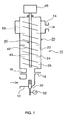
- An agitation mixer 10 comprises a casing 20 in which a flow channel allowing the passage of fluid is formed inside, an agitator body 40 consisting of a shaft 43 installed inside the casing 20 and connected to a vibration source 46 and impeller blades 42 attached to the circumference of the shaft 43, a material inlet 12 placed on the lowermost part of the casing 20 to feed a raw material into the inside of the casing 20, and a steam feeder 30 for injecting steam into the inside of the casing 20.
- the casing 20 is constructed by a plurality of pipes 22 vertically connected end to end and partition plates 24 inserted in between at each junction of the pipes 22. Further, in the casing 20, agitation chambers 26 separated by the partition plates 24 are formed.
- the steam feeder 30 is placed in the proximity of the material inlet 12, and a pressure gage 32 for measuring injection pressure of steam is attached to the steam feeder 30.
- Other material inlets 16 and 18 are also provided in the vicinity of the material inlet 12 to feed second and third materials.
- An outlet 14 for draining out a treated material when treatment of the raw material is completed is mounted to the uppermost part of the casing 20.
- the material inlet 12 is placed on the lower part of the casing 20 and the outlet 14 is placed on the upper part of the casing 20 in this embodiment, the locations of the inlet 12 and the outlet 14 are not limited to those described above and may be interchanged in a vertical direction.
- treatment is used in a broader sense including dissolution, heating, heat-fusion, heat-melting, fluidity enhancement, reactivity improvement (for example, improvement in reaction rate).
- a filter 50 is placed so as to surround the agitator body 40 in one agitation chamber 26 to which the outlet 14 is mounted.
- the filter 50 even if untreated substances (for example, agglomerates or lumps) of a raw material are present in the casing 20, the untreated substances are filtered out so that only treated material can be delivered from the outlet 14.
- the untreated substances (for example, agglomerates or lumps) of the raw material are agitated again in the agitation mixer 10.
- a filtering member made of stainless steel or a ceramic having a mesh size in the order of microns (fine mesh), a reverse osmosis membrane, a polymer membrane (nanofilter membrane), etc. may be used for the filter 50.
- PVA powder polyvinyl alcohol resin powder
- the PVA powder is fed from the material inlet 12 into the casing 20 in which the agitator body 40 driven by the vibration source 46 is vibrating up and down, whereas steam is injected from the steam feeder 30 concurrently with feeding of the PVA powder.
- the amount of steam injected from the steam feeder 30 may preferably be specified to a volume necessary for a desired high concentration of a solution and allowing the PVA powder inside the casing 20 to reach a temperature sufficient for dissolving the PVA powder.
- the PVA powder can be dissolved in a shorter time even though the amount of steam is not increased. For example, by raising the injection pressure, the steam which causes the PVA powder to dissolve can be set to a substantially higher temperature than the temperature set at normal pressure.
- the PVA powder is entrained and upwardly transported by steam through the agitation chambers 26, and then dissolved by heat. As a result of heat dissolution, the PVA powder is transformed into a high concentration of a PVA solution, which is filtered by the filter 50, and finally drained out from the outlet 14.
- the time elapsed from feeding of the PVA powder to formation of a high concentration of the PVA solution is approximately 15 seconds.
- the agitation mixer can significantly shorten the time required for the treatment compared with a conventional steam feeding device for injecting steam into a tank with impeller blades.
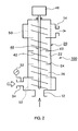
- FIG. 2 another structure of the agitation mixer according to a second embodiment of this invention will be discussed below.
- components similar to those described in the previous embodiment are identified by the same reference numerals and their description is not repeated.
- An agitation mixer 100 comprises the casing 20 in which a flow channel allowing the passage of fluid is formed inside, the agitator body 40 consisting of the shaft 43 installed inside the casing 20 and connected to the vibration source 46 and impeller blades 42 attached to the circumference of the shaft 43, the material inlet 12 placed on the lowermost part of the casing 20 to feed a raw material into the inside of the casing 20, and a steam inlet 34 from which steam is injected into the inside of the casing 20.
- the steam inlet 34 is mounted to the lowest stage of the casing 20, and a filter 52 is placed so as to surround the agitator body 40 in one agitation chamber 26 to which the steam inlet 34 is mounted. In this manner, steam is fed to the inside of the casing 20 through the filter 52 in the form of a uniform mist having a desired size converted by the filter 52.
- the pressure gage 32 for measuring injection pressure of steam is attached to the steam inlet 34.
- the outlet 14 from which a treated material is ejected when treatment of the raw material is completed is mounted to the uppermost part of the casing 20.
- the material inlet 12 is placed on the lower part of the casing 20 and the outlet 14 is placed on the upper part of the casing 20 in this embodiment, the locations of the inlet 12 and the outlet 14 are not limited to those described above and may be interchanged in a vertical direction as described above.
- the filter 50 is also placed so as to surround the agitator body 40 in one agitation chamber 26 to which the outlet 14 is mounted.
- the filter 50 even if untreated substances (for example, agglomerates or lumps) of a raw material are present in the casing 20, the untreated substances are filtered out so that only treated material can be delivered from the outlet 14.
- the untreated substances (for example, agglomerates or lumps) of the raw material are agitated again in the agitation mixer 100.
- a filtering member made of stainless steel or a ceramic having a mesh size in the order of microns (fine mesh), a reverse osmosis membrane, a polymer membrane (nanofilter membrane), etc. may be used for the filters 50 and 52.
- the PVA powder is fed from the material inlet 12 into the casing 20 in which the agitator body 40 driven by the vibration source 46 is vibrating up and down, whereas steam is injected from the steam inlet 34 concurrently with feeding of the PVA powder.
- the steam is converted into the uniform mist passing through the filter 52 and fed into the inside of the casing 20 in the form of the uniform mist.
- the amount of steam injected from the steam inlet 34 may preferably be specified to a volume necessary for a desired high concentration of the solution and allowing the PVA powder inside the casing 20 to reach a temperature sufficient for dissolving the PVA powder. Further, by regulating the injection pressure of steam continuously measured by the pressure gage 32, the PVA powder can be dissolved in a shorter time even though the amount of steam is not increased.
- the PVA powder is entrained and upwardly transported by steam through the agitation chambers 26, and dissolved by heat. As a result of heat dissolution, the PVA powder is transformed into a high concentration of a uniform PVA solution, which is filtered by the filter 50 and finally delivered out from the outlet 14.
- the time elapsed from feeding of the PVA powder to formation of a high concentration of the PVA solution is approximately 15 seconds.
- the agitation mixer can significantly shorten the time required for the treatment compared with the above-described conventional device.
- An agitation mixer 200 comprises the casing 20 in which a flow channel allowing the passage of fluid is formed inside, the agitator body 40 consisting of the shaft 43 installed inside the casing 20 and connected to the vibration source 46 and impeller blades 42 attached to the circumference of the shaft 43, and the material inlet 12 placed on the lower part of the casing 20 to feed a raw material into the inside of the casing 20.
- a steam inlet 36a, 36b, 36c, or 36d is mounted to each of the agitation chambers 26 in the casing 20 to individually inject steam into the agitation chambers 26.
- Pressure gages 32a, 32b, 32c, and 32d for measuring injection pressure of steam are attached to the steam inlets 36a, 36b, 36c, and 36d, respectively.
- the outlet 14 from which a treated material is ejected when treatment of the raw material is completed is mounted to the uppermost part of the casing 20.
- the material inlet 12 is placed on the lower part of the casing 20 and the outlet 14 is placed on the upper part of the casing 20 in this embodiment, the locations of the inlet 12 and the outlet 14 are not limited to those described above and may be interchanged in a vertical direction as described above.
- the filter 50 is placed so as to surround the agitator body 40 in one agitation chamber 26 to which the outlet 14 is mounted.
- the filter 50 even if untreated substances (for example, agglomerates or lumps) of a raw material are present in the casing 20, the untreated substances are filtered out so that only treated material can be delivered from the outlet 14.
- the untreated substances (for example, agglomerates or lumps) of the raw material may be agitated again in the agitation mixer 200.
- a filtering member made of stainless steel or a ceramic having a mesh size in the order of microns (fine mesh), a reverse osmosis membrane, a polymer membrane (nanofilter membrane), etc. may be used for the filter 50 as in the case of the previous embodiments.
- the PVA powder is fed from the material inlet 12 into the casing 20 in which the agitator body 40 driven by the vibration source 46 is vibrating up and down, whereas steam is injected from the steam inlets 36a, 36b, 36c, and 36d concurrently with feeding of the PVA powder.
- the amounts of steam injected from the steam inlets 36a, 36b, 36c, and 36d may preferably be specified, as in the case with the previous embodiments, to a volume necessary for a desired high concentration of the PVA solution and allowing the PVA powder inside the casing 20 to reach a temperature sufficient for dissolving the PVA powder.
- the amounts of steam fed from the steam inlets 36a, 36b, 36c, and 36d may be equal to each other, or may differ from each other. Further, by regulating the injection pressures of steam continuously measured by the pressure gages 32a, 32b, 32c, and 32d, the PVA powder can be dissolved in a shorter time even though the total amount of steam is not increased.
- the PVA powder is entrained and upwardly transported by steam fed from the steam inlets 36a, 36b, 36c, and 36d mounted to the agitation chambers 26, and dissolved by heat.
- the PVA powder is transformed into a high concentration of a uniform PVA solution, which is filtered by the filter 50 and finally delivered out from the outlet 14.
- the entire internal space of the casing 20 is evenly maintained at a constant temperature by the steam injected from the steam inlets 36a, 36b, 36c, and 36d separately mounted to each of the agitation chambers 26, the above-described time elapsed from feeding of the PVA powder to formation of a high concentration of the PVA solution can be shortened further from the 15 seconds indicated in the previous embodiments.
- the steam inlet is provided to every one of the agitation chambers 26, provision of the steam inlet is not limited to this manner.
- the steam inlet may be mounted to alternate agitation chambers 26 or mounted only to a lower set of the successive agitation chambers.
- the ingredient of the steam may be made of, but not limited to, water vapor.
- a solvent suitably compatible with a powder may be selected as appropriate for use in the steam, and two or more solvents may be utilized in combination.
- dissolving a powder was taken as an example of application in the above description regarding Embodiments 1 to 3.
- application of this invention is not limited to the example, and taking a liquid or a fluid as the raw material, the viscosity of the raw material may be depressed to enhance the fluidity thereof.
- the fluidity of the liquid or the fluid may be controlled by injecting steam into the inside of the casing 20 to increase an internal temperature of the casing 20. After reaching desired fluidity, the liquid or the fluid may be ejected from the outlet 14.
- the agitation mixer according to any one of Embodiments 1 to 3 may be used for heat fusion or heat melting of a powder using steam.
- agitation mixers described in the above embodiments and illustrated in Figs. 1 to 3 can be used as a pasteurizer or a cleaning device.
- a subject material to be pasteurized is fed into the inside of the casing 20 from the material inlet 12, and water vapor or vapor of alcohols is injected as steam from the steam feeder 30 (shown in Fig. 1), the steam inlet 34 (shown in Fig. 2), or a set of the steam inlets 36a, 36b, 36c, and 36d (shown in Fig. 3).
- the subject material to be pasteurized is pasteurized or sterilized in each of the agitation chambers 26 by heat of the steam or, if the steam is made of alcohols, by bactericidal action of alcohols in addition to heat of the steam while moving upward, and collected from the outlet 14 as a pasteurized material. It is preferable to appropriately select the mesh size of the filter 50 according to a grain size of the subject material to be pasteurized.
- a subject material to be cleaned is exposed to the heat of steam, or, if the steam is made of alcohols, brought into contact with the alcohols as well as being exposed to the heat of steam.
- impurities occurring on the surface or in the inside of the subject material to be cleaned are vaporized by the heat of steam, or cleaned by the alcohols as well as, in some cases, being azeotroped with the alcohols when the steam consists of alcohols.
- the subject material to be cleaned is delivered upward while being isolated form the impurities in the casing 20, and the isolated subject matter and the impurities are finally collected at different times from the outlet 14.
- the agitation mixer of this invention may be applied to uses for dissolving a powder in a small amount of a solvent, for heat-fusing or heat-melting a powder, for depressing the viscosity of a liquid or a fluid to enhance the fluidity thereof, and for increasing the rate or the efficiency of reaction of a liquid or a fluid.
- the agitation mixer of this invention may be used for removing unreacted monomers remaining after polymerizing monomers and a solvent used for polymerization through azeotropy using steam.
Landscapes
- Chemical & Material Sciences (AREA)
- Chemical Kinetics & Catalysis (AREA)
- Health & Medical Sciences (AREA)
- Animal Behavior & Ethology (AREA)
- General Health & Medical Sciences (AREA)
- Public Health (AREA)
- Veterinary Medicine (AREA)
- Life Sciences & Earth Sciences (AREA)
- Organic Chemistry (AREA)
- Epidemiology (AREA)
- Accessories For Mixers (AREA)
- Cleaning By Liquid Or Steam (AREA)
- Apparatus For Disinfection Or Sterilisation (AREA)
- Mixers With Rotating Receptacles And Mixers With Vibration Mechanisms (AREA)
Applications Claiming Priority (2)
| Application Number | Priority Date | Filing Date | Title |
|---|---|---|---|
| JP2003292785A JP4588305B2 (ja) | 2003-08-13 | 2003-08-13 | 撹拌混合装置および殺菌装置および洗浄装置 |
| JP2003292785 | 2003-08-13 |
Publications (2)
| Publication Number | Publication Date |
|---|---|
| EP1508364A1 EP1508364A1 (en) | 2005-02-23 |
| EP1508364B1 true EP1508364B1 (en) | 2006-10-04 |
Family
ID=34056203
Family Applications (1)
| Application Number | Title | Priority Date | Filing Date |
|---|---|---|---|
| EP04018361A Expired - Lifetime EP1508364B1 (en) | 2003-08-13 | 2004-08-03 | Agitation mixer, pasteurizer, and cleaning device |
Country Status (5)
| Country | Link |
|---|---|
| US (1) | US7350961B2 (enExample) |
| EP (1) | EP1508364B1 (enExample) |
| JP (1) | JP4588305B2 (enExample) |
| BR (1) | BRPI0403224A (enExample) |
| DE (1) | DE602004002635T2 (enExample) |
Families Citing this family (33)
| Publication number | Priority date | Publication date | Assignee | Title |
|---|---|---|---|---|
| US7090391B2 (en) * | 2002-09-25 | 2006-08-15 | Reika Kogyo Kabushiki Kaisha | Apparatus and method for mixing by agitation in a multichambered mixing apparatus including a pre-agitation mixing chamber |
| WO2004082817A1 (de) * | 2003-03-21 | 2004-09-30 | Ifac Gmbh & Co. Kg | Vorrichtung und verfahren zur kontinuierlichen herstellung von emulsionen oder dispersionen |
| JP4588305B2 (ja) * | 2003-08-13 | 2010-12-01 | 冷化工業株式会社 | 撹拌混合装置および殺菌装置および洗浄装置 |
| KR101248672B1 (ko) * | 2004-09-15 | 2013-03-28 | 가부시끼가이샤 구레하 | 고액 접촉을 위한 장치 및 방법 |
| JP2006187756A (ja) * | 2004-12-07 | 2006-07-20 | Reika Kogyo Kk | 撹拌混合装置 |
| WO2006110023A1 (en) * | 2005-04-11 | 2006-10-19 | Broockeville Corporation N.V. | A two-component mixing and dispensing device |
| JP4759760B2 (ja) * | 2005-07-22 | 2011-08-31 | 本多電子株式会社 | 微細霧化粒子洗浄装置 |
| US8123394B2 (en) * | 2005-10-17 | 2012-02-28 | Evonik Degussa Gmbh | Mixer for liquid colorants and method for mixing liquid colorants |
| GB0523245D0 (en) * | 2005-11-15 | 2005-12-21 | Nitech Solutions Ltd | Improved apparatus and method for applying oscillatory motion |
| JP4817973B2 (ja) * | 2006-06-05 | 2011-11-16 | 冷化工業株式会社 | 原料撹拌混合システム |
| ATE518634T1 (de) * | 2007-09-27 | 2011-08-15 | Sulzer Chemtech Ag | Vorrichtung zur erzeugung einer reaktionsfähigen fliessfähigen mischung und deren verwendung |
| CN102019284B (zh) * | 2011-01-07 | 2012-05-23 | 天津环泽塑皿加工有限责任公司 | 非医疗废物自动清洗机 |
| CN103157401A (zh) * | 2013-03-29 | 2013-06-19 | 北京中衡国通能源科技有限责任公司 | 振动激荡式混合装置 |
| JP6138582B2 (ja) * | 2013-05-23 | 2017-05-31 | 冷化工業株式会社 | 粉液混合分散システム |
| CN103585648B (zh) | 2013-10-15 | 2016-04-20 | 英孚伦斯亚洲有限公司 | 自动旋转高压灭菌器及具有连续操作阶段的处理方法 |
| JP6312306B2 (ja) * | 2014-02-03 | 2018-04-18 | ライオン株式会社 | 混合装置の洗浄方法 |
| JP6834960B2 (ja) * | 2015-08-26 | 2021-02-24 | 株式会社サタケ | 過熱蒸気殺菌装置 |
| CN105664762B (zh) * | 2016-01-26 | 2018-05-01 | 佛山市高明鸿源纸业有限公司 | 一种用于双胶纸表面施胶的熬制设备 |
| CN105797670A (zh) * | 2016-05-26 | 2016-07-27 | 安庆盛峰化工股份有限公司 | 一种邻苯二甲酸二异丁酯中和、水洗、脱醇一体化反应釜 |
| CN106076225A (zh) * | 2016-08-16 | 2016-11-09 | 安庆钰龙橡塑机械制造有限公司 | 具有调节功能与振动功能的可移动智能搪玻璃反应容器 |
| CN106076234A (zh) * | 2016-08-16 | 2016-11-09 | 安庆钰龙橡塑机械制造有限公司 | 一种具有调节功能的搪玻璃反应罐 |
| CN106215831A (zh) * | 2016-08-16 | 2016-12-14 | 安庆钰龙橡塑机械制造有限公司 | 一种具有振动功能的可移动智能搪玻璃反应容器 |
| CN106076226A (zh) * | 2016-08-16 | 2016-11-09 | 安庆钰龙橡塑机械制造有限公司 | 一种具有振动功能与调节功能的可移动搪玻璃反应罐 |
| CN106215829A (zh) * | 2016-08-16 | 2016-12-14 | 安庆钰龙橡塑机械制造有限公司 | 一种具有调节功能与振动功能的智能搪玻璃反应容器 |
| KR101890879B1 (ko) | 2017-01-25 | 2018-08-22 | 주식회사 리노셈 | 의료기기용 세척기 |
| CN111212664A (zh) * | 2017-10-16 | 2020-05-29 | 菲德克控股股份有限公司 | 粉末灭菌方法以及粉末灭菌设备 |
| CN108787602B (zh) * | 2018-06-02 | 2021-01-15 | 江门市新会区泰盛石场有限公司 | 一种采矿用叶片传送式矿石杂质去除设备 |
| CN109965227B (zh) * | 2018-12-25 | 2022-04-26 | 宿州市百年传奇食品有限公司 | 一种鸡丝脆骨无菌混滚装置及方法 |
| CN112169614A (zh) * | 2020-08-11 | 2021-01-05 | 盐城工学院 | 一种用于碳纤维复合型材料生产的原料混合装置 |
| CN113083077A (zh) * | 2021-04-23 | 2021-07-09 | 海欣食品股份有限公司 | 一种自动化鱼浆生产处理装置 |
| CN113083078A (zh) * | 2021-04-23 | 2021-07-09 | 海欣食品股份有限公司 | 一种鱼浆加工处理设备 |
| CN113244825A (zh) * | 2021-06-18 | 2021-08-13 | 山东奥扬新能源科技股份有限公司 | 一种瓶体生产用胶液原料混合机 |
| CN114011352A (zh) * | 2021-11-05 | 2022-02-08 | 华大化学(安徽)有限公司 | 湿法合成聚氨酯树脂的高温汽蒸装置 |
Family Cites Families (69)
| Publication number | Priority date | Publication date | Assignee | Title |
|---|---|---|---|---|
| USRE26257E (en) * | 1967-08-29 | Method of cooking grain in a closed system | ||
| DE970926C (de) * | 1948-02-05 | 1958-11-13 | Mueller Hans | Vorrichtung zum Mischen, Ruehren usw. von Fluessigkeiten |
| US2667407A (en) * | 1949-02-11 | 1954-01-26 | Standard Oil Dev Co | Liquid-liquid contact method and apparatus |
| GB689974A (en) | 1949-02-11 | 1953-04-08 | Standard Oil Dev Co | Improvements in or relating to apparatus for contacting of liquids with liquids or gases |
| US2681798A (en) * | 1950-04-11 | 1954-06-22 | Muller Hans | Device for mixing, stirring, emulsifying, and pumping, and the acceleration of chemical and physical reactions by vibration |
| US2604386A (en) * | 1950-12-19 | 1952-07-22 | Clayton Manufacturing Co | Detergent dissolving apparatus |
| GB876070A (en) * | 1957-05-20 | 1961-08-30 | Hoffmann La Roche | An improved countercurrent extraction apparatus |
| FR1195160A (fr) | 1957-05-20 | 1959-11-16 | Hoffmann La Roche | Dispositif pour l'extraction de liquides |
| GB994789A (en) * | 1960-10-01 | 1965-06-10 | Basf Ag | Process and apparatus for the continuous polymerisation of ethylenically unsaturatedpolymerisable compounds |
| NL269692A (enExample) | 1961-09-29 | |||
| DE1243144B (de) * | 1962-08-20 | 1967-06-29 | Dr Ludwig Ziehl | Extraktionskolonne zur Fluessig-Fluessig-Extraktion |
| US3855368A (en) * | 1972-04-26 | 1974-12-17 | Ceskoslovenska Akademie Ved | Apparatus for bringing fluid phases into mutual contact |
| US4128052A (en) * | 1975-02-05 | 1978-12-05 | Gebrueder Buehler Ag | Apparatus for moistening whole grains |
| US4099267A (en) * | 1977-04-04 | 1978-07-04 | Woodrow King | Apparatus for mixing granular fertilizer and/or lawn treatment liquid in water |
| US4259021A (en) * | 1978-04-19 | 1981-03-31 | Paul R. Goudy, Jr. | Fluid mixing apparatus and method |
| US4205094A (en) * | 1978-05-03 | 1980-05-27 | The Procter & Gamble Company | Texturizing and steam deflavoring soy protein with high-speed turbine mixing |
| US4737349A (en) * | 1985-11-01 | 1988-04-12 | Ciba-Geigy Corporation | Tubular reactor for heterogeneous reactions |
| JPS62125836A (ja) * | 1985-11-22 | 1987-06-08 | Reika Kogyo Kk | ミキサ装置 |
| JPH0243933A (ja) * | 1988-08-03 | 1990-02-14 | Reika Kogyo Kk | 攪拌装置 |
| JPS6344927A (ja) * | 1986-08-12 | 1988-02-25 | Reika Kogyo Kk | ミキサ装置 |
| US4983045A (en) * | 1985-11-22 | 1991-01-08 | Reica Corporation | Mixer |
| DE3628012A1 (de) * | 1986-08-19 | 1988-02-25 | Avgust Vasilevic Osipov | Verfahren und vorrichtung zum durchmischen eines heterogenen mediums |
| JPS63319030A (ja) * | 1987-06-22 | 1988-12-27 | Reika Kogyo Kk | エジエクタ |
| JPH01231929A (ja) * | 1988-03-11 | 1989-09-18 | Reika Kogyo Kk | 攪拌装置 |
| JP2815394B2 (ja) * | 1989-05-02 | 1998-10-27 | 冷化工業株式会社 | 混合装置の製造方法および混合装置 |
| JPH03157129A (ja) * | 1989-11-16 | 1991-07-05 | Mita Ind Co Ltd | 分散装置 |
| JP3179086B2 (ja) * | 1990-03-07 | 2001-06-25 | 冷化工業株式会社 | 混合装置 |
| DE4106998C2 (de) * | 1990-03-07 | 1997-08-14 | Reica Corp | Mischvorrichtung |
| DE4037957C2 (de) * | 1990-11-29 | 1996-06-27 | Bliesener Dieter | Homogenisiervorrichtung |
| US5375926A (en) * | 1992-09-14 | 1994-12-27 | Nihon Techno Kabushiki Kaisha | Apparatus for mixing and dispensing fluid by flutter of vibrating vanes |
| JPH0751557A (ja) * | 1993-08-18 | 1995-02-28 | Reika Kogyo Kk | 撹拌混合装置 |
| JPH07286149A (ja) * | 1994-04-19 | 1995-10-31 | Mitsubishi Heavy Ind Ltd | 製糊装置 |
| JPH08103607A (ja) * | 1994-10-06 | 1996-04-23 | Reika Kogyo Kk | 濾過装置 |
| US5829873A (en) * | 1995-12-14 | 1998-11-03 | King; Woodrow | Apparatus for mixing granular fertilizer and/or lawn treatment liquid in water |
| EP0780056A1 (en) * | 1995-12-22 | 1997-06-25 | Societe Des Produits Nestle S.A. | Apparatus and method for treating a fluid product |
| EP0813900A1 (en) * | 1996-03-28 | 1997-12-29 | Union Carbide Chemicals & Plastics Technology Corporation | Continuous, squeeze flow mixing process |
| JP3559660B2 (ja) * | 1996-10-11 | 2004-09-02 | 良平 林 | 連続加熱装置 |
| US5983045A (en) * | 1996-11-14 | 1999-11-09 | Canon Kabushiki Kaisha | Image forming apparatus for forming plural toner images on photosensitive member and for transferring toner images onto transfer material collectively |
| JP3860883B2 (ja) * | 1997-05-30 | 2006-12-20 | 冷化工業株式会社 | 熱交換器 |
| JP3921600B2 (ja) * | 1997-08-25 | 2007-05-30 | 冷化工業株式会社 | 撹拌混合装置 |
| DE19749315A1 (de) * | 1997-11-07 | 1999-05-12 | Emtec Magnetics Gmbh | Verfahren zur Herstellung einer Magnetdispersion für Magnetaufzeichnungsträger und damit hergestellter Magnetaufzeichnungsträger |
| JPH11169697A (ja) * | 1997-12-12 | 1999-06-29 | Reika Kogyo Kk | エマルション製造装置及びエマルションの製造方法 |
| JPH11226377A (ja) * | 1998-02-17 | 1999-08-24 | Reika Kogyo Kk | 撹拌混合装置 |
| US6655826B1 (en) * | 1998-02-25 | 2003-12-02 | Eliseo Alfredo Bonilla Leanos | Device for the treatment of liquids by mechanical vibration |
| JP2000051675A (ja) * | 1998-08-12 | 2000-02-22 | Reika Kogyo Kk | 撹拌混合装置及びこれを用いた撹拌混合方法 |
| JP2000176270A (ja) * | 1998-12-17 | 2000-06-27 | Mitsubishi Electric Corp | 撹拌混合や流体搬送等を行う振動装置 |
| JP2000246131A (ja) * | 1998-12-29 | 2000-09-12 | Reika Kogyo Kk | 振動型分散粉砕装置 |
| JP3854006B2 (ja) * | 1999-05-07 | 2006-12-06 | 日本テクノ株式会社 | 流体の振動流動撹拌装置 |
| JP2001046850A (ja) * | 1999-08-16 | 2001-02-20 | Reika Kogyo Kk | 攪拌混合装置 |
| JP4290819B2 (ja) * | 1999-09-14 | 2009-07-08 | 株式会社イーテック | アスファルト乳化物及びその製造方法 |
| JP2001103947A (ja) * | 1999-10-05 | 2001-04-17 | Shinmei Seisakusho:Kk | 家畜飼料の殺菌、乾燥冷却装置 |
| JP4278245B2 (ja) * | 1999-10-12 | 2009-06-10 | 冷化工業株式会社 | 攪拌重合装置 |
| US6214400B1 (en) * | 1999-10-14 | 2001-04-10 | Lyco Manufacturing Inc. | Method for processing food product |
| JP2001239140A (ja) * | 1999-12-22 | 2001-09-04 | Reika Kogyo Kk | 反応攪拌装置、反応分画濾過装置及び分画方法、生成方法、濾過方法 |
| JP2001269153A (ja) * | 2000-03-24 | 2001-10-02 | Shinmei Seisakusho:Kk | 家畜飼料の低圧殺菌方法と低圧殺菌装置 |
| US6605252B2 (en) * | 2000-05-02 | 2003-08-12 | Japan Techno Co., Ltd. | Vibrationally stirring apparatus for sterilization, sterilizing apparatus and sterilizing method |
| JP4226766B2 (ja) | 2000-08-21 | 2009-02-18 | 日本合成化学工業株式会社 | ポリビニルアルコール系フィルムの製造方法 |
| JP3699642B2 (ja) * | 2000-08-21 | 2005-09-28 | 日本合成化学工業株式会社 | ポリビニルアルコール系樹脂水溶液の製造方法 |
| JP3976220B2 (ja) | 2000-08-21 | 2007-09-12 | 日本合成化学工業株式会社 | 偏光膜用ポリビニルアルコール系フィルム |
| JP3677441B2 (ja) | 2000-08-21 | 2005-08-03 | 日本合成化学工業株式会社 | ポリビニルアルコール系フィルムの製造方法 |
| JP2003001083A (ja) * | 2001-06-22 | 2003-01-07 | Reika Kogyo Kk | 振動型攪拌混合装置の液振動防止構造 |
| JP2003047833A (ja) * | 2001-08-07 | 2003-02-18 | Reika Kogyo Kk | 振動型攪拌混合装置 |
| CA2628036C (en) * | 2001-10-16 | 2012-05-15 | Merlin Plastics Alberta Inc. | Label release and separation system |
| US7090391B2 (en) * | 2002-09-25 | 2006-08-15 | Reika Kogyo Kabushiki Kaisha | Apparatus and method for mixing by agitation in a multichambered mixing apparatus including a pre-agitation mixing chamber |
| JP2004290837A (ja) * | 2003-03-27 | 2004-10-21 | Toray Ind Inc | 無機粉末含有ペーストの製造方法 |
| JP4588305B2 (ja) * | 2003-08-13 | 2010-12-01 | 冷化工業株式会社 | 撹拌混合装置および殺菌装置および洗浄装置 |
| JP2005103340A (ja) * | 2003-09-26 | 2005-04-21 | Reika Kogyo Kk | 振動型攪拌混合装置の圧力変化防止構造 |
| US7331702B2 (en) * | 2003-10-31 | 2008-02-19 | Reika Kogyo Kabushiki Kaisha | Agitation mixer |
| JP2006187756A (ja) * | 2004-12-07 | 2006-07-20 | Reika Kogyo Kk | 撹拌混合装置 |
-
2003
- 2003-08-13 JP JP2003292785A patent/JP4588305B2/ja not_active Expired - Fee Related
-
2004
- 2004-07-23 US US10/896,929 patent/US7350961B2/en not_active Expired - Fee Related
- 2004-08-03 DE DE602004002635T patent/DE602004002635T2/de not_active Expired - Lifetime
- 2004-08-03 EP EP04018361A patent/EP1508364B1/en not_active Expired - Lifetime
- 2004-08-12 BR BR0403224-1A patent/BRPI0403224A/pt not_active Application Discontinuation
Also Published As
| Publication number | Publication date |
|---|---|
| DE602004002635D1 (de) | 2006-11-16 |
| US7350961B2 (en) | 2008-04-01 |
| BRPI0403224A (pt) | 2005-08-30 |
| US20050037119A1 (en) | 2005-02-17 |
| DE602004002635T2 (de) | 2007-08-16 |
| EP1508364A1 (en) | 2005-02-23 |
| JP4588305B2 (ja) | 2010-12-01 |
| JP2005058916A (ja) | 2005-03-10 |
Similar Documents
| Publication | Publication Date | Title |
|---|---|---|
| EP1508364B1 (en) | Agitation mixer, pasteurizer, and cleaning device | |
| EP1527812B1 (en) | Agitation mixer | |
| CN101511465B (zh) | 超声液体处理室和连续流动混合系统 | |
| JP2001239140A (ja) | 反応攪拌装置、反応分画濾過装置及び分画方法、生成方法、濾過方法 | |
| KR20100039232A (ko) | 연속적 다중상 반응과 분리를 위한 시스템 및 방법 | |
| TW201105625A (en) | Process for preparing α, β-unsaturated C10-aldehydes | |
| KR970058572A (ko) | 이산화탄소의 초임계 유동물을 이용한 액상 식료품 또는 액상 의약품 가공 방법 및 시스템 | |
| KR20100017806A (ko) | 미세유체 자발적 진동 혼합기 및 장치 및 이를 이용하는 방법 | |
| GB2597397A (en) | Apparatus and method for support removal | |
| JP2004230272A (ja) | 攪拌混合装置 | |
| JP2007038058A (ja) | 液体処理装置および液体供給方法 | |
| Devos et al. | Characterization of a modular microfluidic section for seeded nucleation in multiphase flow | |
| KR100631468B1 (ko) | 초음파 진동으로 액체를 처리하는 방법 및 장치 | |
| SE462287B (sv) | Foerfarande och anlaeggning foer framstaellning av hoegutbytesmassor ur lignocellulosamateial | |
| KR101010643B1 (ko) | 수처리용 약품 혼합공급장치 | |
| RU2158174C1 (ru) | Установка для приготовления многокомпонентных жидкофазных смесей | |
| KR19980086878A (ko) | 처리용기 및 그 용기내에서 실시되는 공정 | |
| RU2053006C1 (ru) | Экстрактор для системы твердое тело - жидкость | |
| US20230256357A1 (en) | Device for solid/liquid extraction by radial ultrasonic irradiation, and associated extraction method | |
| SU745050A1 (ru) | Кавитационный реактор | |
| RU2463100C1 (ru) | Способ проведения реакций и реактор для его осуществления | |
| SU716576A1 (ru) | Ультразвуковое устройство дл обработки суспензий и эмульсий | |
| JP4121274B2 (ja) | マイクロカプセル又は微粒子の半連続製造装置 | |
| CN114082209A (zh) | 一种负压蒸馏苯肼分离提纯设备及方法 | |
| JPH10174862A (ja) | 連続反応装置 |
Legal Events
| Date | Code | Title | Description |
|---|---|---|---|
| PUAI | Public reference made under article 153(3) epc to a published international application that has entered the european phase |
Free format text: ORIGINAL CODE: 0009012 |
|
| AK | Designated contracting states |
Kind code of ref document: A1 Designated state(s): AT BE BG CH CY CZ DE DK EE ES FI FR GB GR HU IE IT LI LU MC NL PL PT RO SE SI SK TR |
|
| AX | Request for extension of the european patent |
Extension state: AL HR LT LV MK |
|
| 17P | Request for examination filed |
Effective date: 20050613 |
|
| GRAP | Despatch of communication of intention to grant a patent |
Free format text: ORIGINAL CODE: EPIDOSNIGR1 |
|
| AKX | Designation fees paid |
Designated state(s): DE FR GB |
|
| GRAS | Grant fee paid |
Free format text: ORIGINAL CODE: EPIDOSNIGR3 |
|
| GRAA | (expected) grant |
Free format text: ORIGINAL CODE: 0009210 |
|
| AK | Designated contracting states |
Kind code of ref document: B1 Designated state(s): DE FR GB |
|
| REG | Reference to a national code |
Ref country code: GB Ref legal event code: FG4D |
|
| REF | Corresponds to: |
Ref document number: 602004002635 Country of ref document: DE Date of ref document: 20061116 Kind code of ref document: P |
|
| ET | Fr: translation filed | ||
| PLBE | No opposition filed within time limit |
Free format text: ORIGINAL CODE: 0009261 |
|
| STAA | Information on the status of an ep patent application or granted ep patent |
Free format text: STATUS: NO OPPOSITION FILED WITHIN TIME LIMIT |
|
| 26N | No opposition filed |
Effective date: 20070705 |
|
| PGFP | Annual fee paid to national office [announced via postgrant information from national office to epo] |
Ref country code: GB Payment date: 20100811 Year of fee payment: 7 |
|
| PGFP | Annual fee paid to national office [announced via postgrant information from national office to epo] |
Ref country code: FR Payment date: 20110826 Year of fee payment: 8 |
|
| GBPC | Gb: european patent ceased through non-payment of renewal fee |
Effective date: 20110803 |
|
| PG25 | Lapsed in a contracting state [announced via postgrant information from national office to epo] |
Ref country code: GB Free format text: LAPSE BECAUSE OF NON-PAYMENT OF DUE FEES Effective date: 20110803 |
|
| REG | Reference to a national code |
Ref country code: FR Ref legal event code: ST Effective date: 20130430 |
|
| PG25 | Lapsed in a contracting state [announced via postgrant information from national office to epo] |
Ref country code: FR Free format text: LAPSE BECAUSE OF NON-PAYMENT OF DUE FEES Effective date: 20120831 |
|
| PGFP | Annual fee paid to national office [announced via postgrant information from national office to epo] |
Ref country code: DE Payment date: 20140822 Year of fee payment: 11 |
|
| REG | Reference to a national code |
Ref country code: DE Ref legal event code: R119 Ref document number: 602004002635 Country of ref document: DE |
|
| PG25 | Lapsed in a contracting state [announced via postgrant information from national office to epo] |
Ref country code: DE Free format text: LAPSE BECAUSE OF NON-PAYMENT OF DUE FEES Effective date: 20160301 |