EP1469701B1 - Microstructures en relief - Google Patents
Microstructures en relief Download PDFInfo
- Publication number
- EP1469701B1 EP1469701B1 EP04076015A EP04076015A EP1469701B1 EP 1469701 B1 EP1469701 B1 EP 1469701B1 EP 04076015 A EP04076015 A EP 04076015A EP 04076015 A EP04076015 A EP 04076015A EP 1469701 B1 EP1469701 B1 EP 1469701B1
- Authority
- EP
- European Patent Office
- Prior art keywords
- sidewall
- diaphragm
- transducer
- raised microstructure
- raised
- Prior art date
- Legal status (The legal status is an assumption and is not a legal conclusion. Google has not performed a legal analysis and makes no representation as to the accuracy of the status listed.)
- Expired - Lifetime
Links
Images


Classifications
-
- H—ELECTRICITY
- H04—ELECTRIC COMMUNICATION TECHNIQUE
- H04R—LOUDSPEAKERS, MICROPHONES, GRAMOPHONE PICK-UPS OR LIKE ACOUSTIC ELECTROMECHANICAL TRANSDUCERS; DEAF-AID SETS; PUBLIC ADDRESS SYSTEMS
- H04R19/00—Electrostatic transducers
- H04R19/04—Microphones
-
- H—ELECTRICITY
- H04—ELECTRIC COMMUNICATION TECHNIQUE
- H04R—LOUDSPEAKERS, MICROPHONES, GRAMOPHONE PICK-UPS OR LIKE ACOUSTIC ELECTROMECHANICAL TRANSDUCERS; DEAF-AID SETS; PUBLIC ADDRESS SYSTEMS
- H04R19/00—Electrostatic transducers
- H04R19/005—Electrostatic transducers using semiconductor materials
-
- H—ELECTRICITY
- H04—ELECTRIC COMMUNICATION TECHNIQUE
- H04R—LOUDSPEAKERS, MICROPHONES, GRAMOPHONE PICK-UPS OR LIKE ACOUSTIC ELECTROMECHANICAL TRANSDUCERS; DEAF-AID SETS; PUBLIC ADDRESS SYSTEMS
- H04R31/00—Apparatus or processes specially adapted for the manufacture of transducers or diaphragms therefor
- H04R31/006—Interconnection of transducer parts
Definitions
- the goal is to create a stiff element at a precise position relative to the diaphragm.
- One method to achieve this is to form the backplate using a silicon nitride thin film deposited over a shaped silicon oxide sacrificial layer which serves to establish the desired separation. This sacrificial layer is later removed through well known etch processes, leaving the raised backplate. Intrinsic tensile stress in the silicon nitride backplate will cause it to deflect out of position. Compressive stress is always avoided as it causes the structure to buckle.
- the object of the present invention is to solve these and other problems.
- the conducting diaphragm 12 is electrically insulated from the substrate 30 by a dielectric layer 31.
- a conducting electrode 42 is attached to the non-conductive perforated member 40.
- the perforated member contains a number of openings 21 through which a sacrificial layer (not shown) between the diaphragm and perforated member is etched during fabrication to form the air gap 20 and which later serve to reduce the acoustic damping of the air in the air gap to provide sufficient bandwidth of the transducer.
- a number of openings are also made in the diaphragm 12 and the perforated member 40 to form a leakage path 14 which together with the compliance of the back chamber (not shown), on which the transducer will be mounted, forms a high-pass filter resulting in a roll-off frequency low enough not to impede the acoustic function of the transducer and high enough to remove the influence of barometric pressure variations.
- the openings 14 are defined by photo lithographic methods and can therefore be tightly controlled, leading to a well defined low frequency behavior of the transducer.
- the attachment of the perforated member 40 along the perimeter 43 can be varied to reduce the curvature of the perforated member due to intrinsic internal bending moments.
- the perimeter can be a continuous curved surface ( FIGS. 1-3 ) or discontinuous, such as corrugated ( FIG. 4 ).
- a discontinuous perimeter 43 provides additional rigidity of the perforated member 40 thereby reducing the curvature due to intrinsic bending moments in the perforated member 40 .
- the transducer 50 includes a conductive diaphragm 12 and a perforated member 40 supported by a substrate 30 and separated by an air gap 20 .
- the diaphragm 12 is attached to the substrate through a number of springs 11 , which serve to mechanically decouple the diaphragm from the substrate, thereby relieving any intrinsic stress in the diaphragm. Moreover, the diaphragm is released for stress in the substrate and device package.
- the conducting diaphragm 12 is electrically insulated from the substrate 30 by a dielectric layer 31 .
- a conducting electrode 42 is attached to the non-conductive perforated member 40 .
- the perforated member contains a number of openings 21 through which a sacrificial layer (not shown) between the diaphragm 12 and the perforated member is etched during fabrication to form the air gap 20 and which later serves to reduce the acoustic damping of the air in the air gap to provide sufficient bandwidth of the transducer.
- a number of openings are made in the support structure 41 to form a leakage path 14 ( FIG.
- an electrical potential is applied between the conductive diaphragm 12 and the electrode 42 on the perforated member.
- the electrical potential and associated charging of the conductors produces an electrostatic attraction force between the diaphragm and the perforated member.
- the free diaphragm 12 moves toward the perforated member 40 until it rests upon the support structure 41 , which sets the initial operating point of the transducer with a well defined air gap 20 and acoustic leakage through path 14 .
- a pressure difference appears across the diaphragm 12 causing it to deflect towards or away from the perforated member 40 .
- the deflection of the diaphragm 12 causes a change of the electrical field, and consequently capacitance, between the diaphragm 12 and the perforated member 40 .
- the electrical capacitance of the transducer is modulated by the acoustical energy.
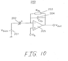
- the amplifier supplies a mirror charge on output side of the feedback capacitor to remove the offset, resulting in a change of output voltage "Vout.”
- the charge gain in this circuit is set by the ratio between the initial transducer capacitance and the capacitance of the feedback capacitor.
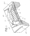
- the raised microstructure 110 comprises a generally circular thin-film plate or backplate 112 supported by a sidewall 114 .
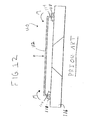
- FIG. 15 shows a plan view of the assembly of FIG. 13 with a surface of the sidewall 114 of the present invention shown in phantom. It can be seen that the sidewall 114 of the present invention as shown in FIGS. 13-15 is ribbed, forming a plurality of periodic ridges 120 and grooves 122. In the preferred embodiment, the ridges 120 and grooves 122 are parallel and equally spaced, forming a corrugated structure. Furthermore, the preferred embodiment utilizes ridges 120 and grooves 122 of a squared cross section. The effect of corrugating the side wall in this manner is to create segments 124 of the sidewall 114 that are radial, as is the intrinsic tension T of the plate 112.
- the sidewall 114 By making portions of the sidewall 114 radial, as is the tension T , the sidewall 114 is stiffened. It has been found that the sidewall 114 of the prior art, which is tangential to plate 112 , is easily bent as compared to the radial segments 124 of the present invention.
- FIGS. 13-15 Other geometries than that shown in FIGS. 13-15 of the corrugations or ridges 120 and grooves 122 can be imagined and used effectively to increase the sidewall's 114 ability to resist moment M and the geometry depicted in the FIGS. 13-15 is not intended to limit the scope of the present invention.
- a generally annular geometry, generally triangular geometry or any combination or variation of these geometries or others could be utilized for the ridges 122 and grooves 124 .
- the corrugations are radial and hence the sidewalls 114 are parallel to the tension in the backplate 112 .
- the sacrificial material is etched in such a way that the sidewalls 114 are sloped with respect to the substrate to allow good step coverage as the thin film backplate 112 is deposited.
Claims (8)
- - Microstructure en relief (110) destinée à être utilisée dans un dispositif à base de silicium, la microstructure en relief (110) comprenant : une plaque en feuille mince (112), généralement plane, ayant une périphérie ; et une paroi latérale (114), caractérisée par le fait que la paroi latérale (114) est à nervures et comprend une pluralité de crêtes (120) et rainures (122), les crêtes et rainures (120, 122) s'étendant sensiblement sur toute la périphérie et étant en outre disposées sensiblement perpendiculairement à une bordure de la plaque en feuille mince (112) définie par la périphérie, la paroi latérale à nervures (114) étant disposée pour supporter la plaque en feuille mince (112), généralement plane, le long de la périphérie ; et par le fait que les différentes crêtes et rainures (120, 122) de la paroi latérale à nervures (114) forment au moins une nervure, et dans laquelle au moins une nervure renforce la paroi latérale à nervures (114).
- - Microstructure en relief selon la revendication 1, dans laquelle les crêtes et rainures (120, 122) de la paroi latérale à nervures (114) sont parallèles et espacées de manière égale pour former une paroi latérale cannelée.
- - Microstructure en relief selon la revendication 1, dans laquelle la nervure (120) a une section transversale généralement arquée.
- - Microstructure en relief selon la revendication 1, dans laquelle la nervure (120) a une section transversale généralement triangulaire.
- - Microstructure en relief selon la revendication 1, dans laquelle la nervure (120) a une section transversale généralement rectangulaire.
- - Microstructure en relief selon la revendication 1, dans laquelle la plaque en feuille mince (112) comprend une plaque d'un transducteur capacitif à base de silicium.
- - Microstructure en relief selon la revendication 1, dans laquelle la plaque en feuille mince (112) comprend une plaque arrière rigide d'un microphone à base de silicium.
- - Microstructure en relief selon la revendication 1, dans laquelle la paroi latérale (114) enferme sensiblement complètement la zone au-dessous de la plaque en feuille mince (112).
Applications Claiming Priority (5)
| Application Number | Priority Date | Filing Date | Title |
|---|---|---|---|
| US910110 | 1978-05-30 | ||
| US63740100A | 2000-08-11 | 2000-08-11 | |
| US637401 | 2000-08-11 | ||
| US09/910,110 US6987859B2 (en) | 2001-07-20 | 2001-07-20 | Raised microstructure of silicon based device |
| EP01959715A EP1310136B1 (fr) | 2000-08-11 | 2001-08-10 | Transducteur a bande large miniature |
Related Parent Applications (1)
| Application Number | Title | Priority Date | Filing Date |
|---|---|---|---|
| EP01959715A Division EP1310136B1 (fr) | 2000-08-11 | 2001-08-10 | Transducteur a bande large miniature |
Publications (3)
| Publication Number | Publication Date |
|---|---|
| EP1469701A2 EP1469701A2 (fr) | 2004-10-20 |
| EP1469701A3 EP1469701A3 (fr) | 2005-11-16 |
| EP1469701B1 true EP1469701B1 (fr) | 2008-04-16 |
Family
ID=27092826
Family Applications (2)
| Application Number | Title | Priority Date | Filing Date |
|---|---|---|---|
| EP04076015A Expired - Lifetime EP1469701B1 (fr) | 2000-08-11 | 2001-08-10 | Microstructures en relief |
| EP01959715A Expired - Lifetime EP1310136B1 (fr) | 2000-08-11 | 2001-08-10 | Transducteur a bande large miniature |
Family Applications After (1)
| Application Number | Title | Priority Date | Filing Date |
|---|---|---|---|
| EP01959715A Expired - Lifetime EP1310136B1 (fr) | 2000-08-11 | 2001-08-10 | Transducteur a bande large miniature |
Country Status (9)
| Country | Link |
|---|---|
| EP (2) | EP1469701B1 (fr) |
| JP (3) | JP4338395B2 (fr) |
| KR (1) | KR100571967B1 (fr) |
| CN (2) | CN1498513B (fr) |
| AT (2) | ATE321429T1 (fr) |
| AU (1) | AU2001281241A1 (fr) |
| DE (2) | DE60118208T2 (fr) |
| DK (2) | DK1469701T3 (fr) |
| WO (1) | WO2002015636A2 (fr) |
Cited By (4)
| Publication number | Priority date | Publication date | Assignee | Title |
|---|---|---|---|---|
| US9779716B2 (en) | 2015-12-30 | 2017-10-03 | Knowles Electronics, Llc | Occlusion reduction and active noise reduction based on seal quality |
| US9812149B2 (en) | 2016-01-28 | 2017-11-07 | Knowles Electronics, Llc | Methods and systems for providing consistency in noise reduction during speech and non-speech periods |
| US9830930B2 (en) | 2015-12-30 | 2017-11-28 | Knowles Electronics, Llc | Voice-enhanced awareness mode |
| US9961443B2 (en) | 2015-09-14 | 2018-05-01 | Knowles Electronics, Llc | Microphone signal fusion |
Families Citing this family (115)
| Publication number | Priority date | Publication date | Assignee | Title |
|---|---|---|---|---|
| US6535460B2 (en) | 2000-08-11 | 2003-03-18 | Knowles Electronics, Llc | Miniature broadband acoustic transducer |
| US6987859B2 (en) | 2001-07-20 | 2006-01-17 | Knowles Electronics, Llc. | Raised microstructure of silicon based device |
| US7434305B2 (en) | 2000-11-28 | 2008-10-14 | Knowles Electronics, Llc. | Method of manufacturing a microphone |
| US7166910B2 (en) | 2000-11-28 | 2007-01-23 | Knowles Electronics Llc | Miniature silicon condenser microphone |
| US7439616B2 (en) | 2000-11-28 | 2008-10-21 | Knowles Electronics, Llc | Miniature silicon condenser microphone |
| US8629005B1 (en) | 2000-11-28 | 2014-01-14 | Knowles Electronics, Llc | Methods of manufacture of bottom port surface mount silicon condenser microphone packages |
| US6859542B2 (en) | 2001-05-31 | 2005-02-22 | Sonion Lyngby A/S | Method of providing a hydrophobic layer and a condenser microphone having such a layer |
| US7023066B2 (en) | 2001-11-20 | 2006-04-04 | Knowles Electronics, Llc. | Silicon microphone |
| KR100437681B1 (ko) * | 2002-04-15 | 2004-06-30 | 부전전자부품 주식회사 | 지향성 마이크로폰 |
| DE10238523B4 (de) | 2002-08-22 | 2014-10-02 | Epcos Ag | Verkapseltes elektronisches Bauelement und Verfahren zur Herstellung |
| US6781231B2 (en) | 2002-09-10 | 2004-08-24 | Knowles Electronics Llc | Microelectromechanical system package with environmental and interference shield |
| JP2004356707A (ja) * | 2003-05-27 | 2004-12-16 | Hosiden Corp | 音響検出機構 |
| US7030536B2 (en) * | 2003-12-29 | 2006-04-18 | General Electric Company | Micromachined ultrasonic transducer cells having compliant support structure |
| JP4201723B2 (ja) * | 2004-02-13 | 2008-12-24 | 東京エレクトロン株式会社 | 容量検知型センサ素子 |
| DE102004020204A1 (de) | 2004-04-22 | 2005-11-10 | Epcos Ag | Verkapseltes elektrisches Bauelement und Verfahren zur Herstellung |
| US7346178B2 (en) * | 2004-10-29 | 2008-03-18 | Silicon Matrix Pte. Ltd. | Backplateless silicon microphone |
| US7329933B2 (en) | 2004-10-29 | 2008-02-12 | Silicon Matrix Pte. Ltd. | Silicon microphone with softly constrained diaphragm |
| JP4539450B2 (ja) | 2004-11-04 | 2010-09-08 | オムロン株式会社 | 容量型振動センサ及びその製造方法 |
| KR100685092B1 (ko) * | 2005-03-14 | 2007-02-22 | 주식회사 케이이씨 | Mems 공정을 이용한 마이크로폰 및 그 제조 방법 |
| US7825484B2 (en) | 2005-04-25 | 2010-11-02 | Analog Devices, Inc. | Micromachined microphone and multisensor and method for producing same |
| US7449356B2 (en) | 2005-04-25 | 2008-11-11 | Analog Devices, Inc. | Process of forming a microphone using support member |
| US7885423B2 (en) | 2005-04-25 | 2011-02-08 | Analog Devices, Inc. | Support apparatus for microphone diaphragm |
| SG127754A1 (en) | 2005-05-16 | 2006-12-29 | Sensfab Pte Ltd | Silicon microphone |
| DE102005031601B4 (de) * | 2005-07-06 | 2016-03-03 | Robert Bosch Gmbh | Kapazitives, mikromechanisches Mikrofon |
| US8351632B2 (en) | 2005-08-23 | 2013-01-08 | Analog Devices, Inc. | Noise mitigating microphone system and method |
| KR20080009735A (ko) | 2005-09-09 | 2008-01-29 | 야마하 가부시키가이샤 | 캐패시터 마이크로폰 |
| KR100765149B1 (ko) * | 2005-10-05 | 2007-10-15 | 전자부품연구원 | 초소형 음향 감지 장치 및 그 제조 방법 |
| KR100785803B1 (ko) * | 2005-12-07 | 2007-12-13 | 한국전자통신연구원 | 판 스프링 구조를 갖는 초소형 마이크로 폰, 스피커 및이를 이용한 음성 인식/합성장치 |
| DE102006001493B4 (de) * | 2006-01-11 | 2007-10-18 | Austriamicrosystems Ag | MEMS-Sensor und Verfahren zur Herstellung |
| CN101371614A (zh) * | 2006-01-20 | 2009-02-18 | 模拟设备公司 | 用于电容式传声器隔膜的支撑设备 |
| JP4811035B2 (ja) * | 2006-01-31 | 2011-11-09 | パナソニック電工株式会社 | 音響センサ |
| JP4737721B2 (ja) * | 2006-03-10 | 2011-08-03 | ヤマハ株式会社 | コンデンサマイクロホン |
| JP2007228345A (ja) * | 2006-02-24 | 2007-09-06 | Yamaha Corp | コンデンサマイクロホン |
| JP4737720B2 (ja) * | 2006-03-06 | 2011-08-03 | ヤマハ株式会社 | ダイヤフラム及びその製造方法並びにそのダイヤフラムを有するコンデンサマイクロホン及びその製造方法 |
| JP4737719B2 (ja) * | 2006-02-24 | 2011-08-03 | ヤマハ株式会社 | コンデンサマイクロホン |
| JP2007267049A (ja) * | 2006-03-29 | 2007-10-11 | Yamaha Corp | コンデンサマイクロホン |
| JP4605470B2 (ja) * | 2006-03-31 | 2011-01-05 | ヤマハ株式会社 | コンデンサマイクロホン |
| GB0605576D0 (en) * | 2006-03-20 | 2006-04-26 | Oligon Ltd | MEMS device |
| TW200746869A (en) | 2006-03-29 | 2007-12-16 | Yamaha Corp | Condenser microphone |
| JP4605544B2 (ja) * | 2006-03-29 | 2011-01-05 | ヤマハ株式会社 | コンデンサマイクロホン |
| WO2008014324A2 (fr) | 2006-07-25 | 2008-01-31 | Analog Devices, Inc. | Système à microphones multiples |
| JP4567643B2 (ja) * | 2006-08-24 | 2010-10-20 | パナソニック株式会社 | コンデンサ及びその製造方法 |
| CN101141832B (zh) * | 2006-09-06 | 2011-04-20 | 歌尔声学股份有限公司 | 单膜电容式传声器芯片 |
| JP2010506532A (ja) * | 2006-10-11 | 2010-02-25 | メムス テクノロジー ビーエイチディー | 極低圧力センサーおよびその製造方法 |
| JP4144640B2 (ja) | 2006-10-13 | 2008-09-03 | オムロン株式会社 | 振動センサの製造方法 |
| US7894622B2 (en) | 2006-10-13 | 2011-02-22 | Merry Electronics Co., Ltd. | Microphone |
| EP1931173B1 (fr) * | 2006-12-06 | 2011-07-20 | Electronics and Telecommunications Research Institute | Microphone condensateur doté d'un diaphragme d'articulation en flexion et son procédé de fabrication |
| CN101584226B (zh) | 2007-01-17 | 2013-08-21 | 美国亚德诺半导体公司 | 带有压力释放的麦克风 |
| JP5034692B2 (ja) * | 2007-06-04 | 2012-09-26 | オムロン株式会社 | 音響センサ |
| JP5029147B2 (ja) * | 2007-06-04 | 2012-09-19 | オムロン株式会社 | 音響センサ |
| JP5412031B2 (ja) * | 2007-07-24 | 2014-02-12 | ローム株式会社 | Memsセンサ |
| GB2453104B (en) | 2007-09-19 | 2012-04-25 | Wolfson Microelectronics Plc | Mems device and process |
| GB2453105B (en) | 2007-09-19 | 2011-01-12 | Wolfson Microelectronics Plc | MEMS device and process |
| GB2452941B (en) * | 2007-09-19 | 2012-04-11 | Wolfson Microelectronics Plc | Mems device and process |
| US20090136064A1 (en) | 2007-09-28 | 2009-05-28 | Yamaha Corporation | Vibration transducer and manufacturing method therefor |
| JP2009089100A (ja) * | 2007-09-28 | 2009-04-23 | Yamaha Corp | 振動トランスデューサ |
| US8045733B2 (en) * | 2007-10-05 | 2011-10-25 | Shandong Gettop Acoustic Co., Ltd. | Silicon microphone with enhanced impact proof structure using bonding wires |
| KR100932754B1 (ko) * | 2007-12-12 | 2009-12-21 | 에스텍 주식회사 | 다기능 스피커 |
| US7888754B2 (en) | 2007-12-28 | 2011-02-15 | Yamaha Corporation | MEMS transducer |
| KR101113366B1 (ko) * | 2008-02-20 | 2012-03-02 | 오므론 가부시키가이샤 | 정전 용량형 진동 센서 |
| JP5332373B2 (ja) | 2008-07-25 | 2013-11-06 | オムロン株式会社 | 静電容量型振動センサ |
| JP4419103B1 (ja) | 2008-08-27 | 2010-02-24 | オムロン株式会社 | 静電容量型振動センサ |
| JP2010074523A (ja) * | 2008-09-18 | 2010-04-02 | Rohm Co Ltd | 犠牲層のエッチング方法、memsデバイスの製造方法およびmemsデバイス |
| JP2010155306A (ja) | 2008-12-26 | 2010-07-15 | Panasonic Corp | Memsデバイス及びその製造方法 |
| GB2467848B (en) * | 2009-02-13 | 2011-01-12 | Wolfson Microelectronics Plc | MEMS device and process |
| US8363860B2 (en) | 2009-03-26 | 2013-01-29 | Analog Devices, Inc. | MEMS microphone with spring suspended backplate |
| EP2239961A1 (fr) * | 2009-04-06 | 2010-10-13 | Nxp B.V. | Plaque arrière pour microphone |
| DE102009026682A1 (de) * | 2009-06-03 | 2010-12-09 | Robert Bosch Gmbh | Bauelement mit einer mikromechanischen Mikrofonstruktur und Verfahren zu dessen Herstellung |
| JP5513813B2 (ja) * | 2009-08-31 | 2014-06-04 | 新日本無線株式会社 | Memsマイクロフォンおよびその製造方法 |
| CN102056061A (zh) * | 2009-10-29 | 2011-05-11 | 苏州敏芯微电子技术有限公司 | 电容式微型硅麦克风及其制造方法 |
| DE102010000666A1 (de) * | 2010-01-05 | 2011-07-07 | Robert Bosch GmbH, 70469 | Bauelement mit einer mikromechanischen Mikrofonstruktur und Verfahren zu dessen Herstellung |
| CN102223591B (zh) * | 2010-04-19 | 2015-04-01 | 联华电子股份有限公司 | 微机电系统麦克风的晶片级封装结构及其制造方法 |
| JP4947220B2 (ja) | 2010-05-13 | 2012-06-06 | オムロン株式会社 | 音響センサ及びマイクロフォン |
| JP5402823B2 (ja) | 2010-05-13 | 2014-01-29 | オムロン株式会社 | 音響センサ |
| JP5400708B2 (ja) | 2010-05-27 | 2014-01-29 | オムロン株式会社 | 音響センサ、音響トランスデューサ、該音響トランスデューサを利用したマイクロフォン、および音響トランスデューサの製造方法 |
| JP2012070120A (ja) * | 2010-09-22 | 2012-04-05 | Panasonic Corp | センサ |
| CN102740203A (zh) * | 2011-04-06 | 2012-10-17 | 美律实业股份有限公司 | 结合式微机电麦克风及其制造方法 |
| US20120328132A1 (en) * | 2011-06-27 | 2012-12-27 | Yunlong Wang | Perforated Miniature Silicon Microphone |
| EP2774390A4 (fr) | 2011-11-04 | 2015-07-22 | Knowles Electronics Llc | Membrane diélectrique intégrée en vue de servir de barrière dans un dispositif acoustique, et procédé pour sa fabrication |
| JP5177309B1 (ja) * | 2012-01-31 | 2013-04-03 | オムロン株式会社 | 静電容量型センサ |
| US9078063B2 (en) | 2012-08-10 | 2015-07-07 | Knowles Electronics, Llc | Microphone assembly with barrier to prevent contaminant infiltration |
| DE102012215251A1 (de) * | 2012-08-28 | 2013-03-21 | Robert Bosch Gmbh | MEMS-Bauelement |
| JP5987572B2 (ja) | 2012-09-11 | 2016-09-07 | オムロン株式会社 | 音響トランスデューサ |
| JP5991475B2 (ja) | 2012-09-14 | 2016-09-14 | オムロン株式会社 | 音響トランスデューサ |
| CN102873020B (zh) * | 2012-10-12 | 2015-05-06 | 北京七星华创电子股份有限公司 | 兆声波换能器的连接盖 |
| KR101496817B1 (ko) * | 2013-08-09 | 2015-02-27 | 삼성전기주식회사 | 음향 변환기 |
| JP6179300B2 (ja) | 2013-09-13 | 2017-08-16 | オムロン株式会社 | 音響トランスデューサ、およびマイクロホン |
| JP6345926B2 (ja) * | 2013-10-07 | 2018-06-20 | 新日本無線株式会社 | Mems素子およびその製造方法 |
| US20150162523A1 (en) | 2013-12-06 | 2015-06-11 | Murata Manufacturing Co., Ltd. | Piezoelectric device |
| DE102014202009A1 (de) * | 2014-02-05 | 2015-08-06 | Robert Bosch Gmbh | Verfahren und Mittel zum Regeln der elektrischen Vorspannung am Messkondensator eines MEMS-Sensorelements |
| US20150296306A1 (en) * | 2014-04-10 | 2015-10-15 | Knowles Electronics, Llc. | Mems motors having insulated substrates |
| CN105359553A (zh) | 2014-06-27 | 2016-02-24 | 歌尔声学股份有限公司 | 具有悬挂式振膜的硅麦克风和具有该硅麦克风的系统 |
| CN105323687A (zh) * | 2014-07-14 | 2016-02-10 | 北京卓锐微技术有限公司 | 一种多晶硅层上设置有突起的硅电容麦克风及其制备方法 |
| CN104105041B (zh) * | 2014-07-31 | 2019-01-04 | 歌尔股份有限公司 | 硅基mems麦克风及其制作方法 |
| US9743191B2 (en) | 2014-10-13 | 2017-08-22 | Knowles Electronics, Llc | Acoustic apparatus with diaphragm supported at a discrete number of locations |
| US9872116B2 (en) | 2014-11-24 | 2018-01-16 | Knowles Electronics, Llc | Apparatus and method for detecting earphone removal and insertion |
| US9794661B2 (en) | 2015-08-07 | 2017-10-17 | Knowles Electronics, Llc | Ingress protection for reducing particle infiltration into acoustic chamber of a MEMS microphone package |
| US9859879B2 (en) | 2015-09-11 | 2018-01-02 | Knowles Electronics, Llc | Method and apparatus to clip incoming signals in opposing directions when in an off state |
| CN106841396B (zh) * | 2015-12-03 | 2019-05-28 | 中国科学院上海微系统与信息技术研究所 | 硅基电容式声发射传感器及其制备方法 |
| KR101807071B1 (ko) | 2016-10-06 | 2017-12-08 | 현대자동차 주식회사 | 마이크로폰 및 그 제조 방법 |
| KR101807069B1 (ko) * | 2016-10-21 | 2017-12-08 | 현대자동차 주식회사 | 마이크로폰 및 그 제조방법 |
| JP6930101B2 (ja) * | 2016-12-12 | 2021-09-01 | オムロン株式会社 | 音響センサ及び静電容量型トランスデューサ |
| KR102322258B1 (ko) * | 2017-05-19 | 2021-11-04 | 현대자동차 주식회사 | 마이크로폰 및 그 제조 방법 |
| DE102017217151B3 (de) | 2017-09-27 | 2019-01-03 | Robert Bosch Gmbh | Mikromechanischer Sensor |
| JP7067891B2 (ja) | 2017-10-18 | 2022-05-16 | Mmiセミコンダクター株式会社 | トランスデューサ |
| DE112019004970T5 (de) | 2018-10-05 | 2021-06-24 | Knowles Electronics, Llc | Mikrofonvorrichtung mit Eindringschutz |
| WO2020072904A1 (fr) * | 2018-10-05 | 2020-04-09 | Knowles Electronics, Llc | Transducteurs acoustiques à zone basse pression et diaphragmes comprenant une conformité améliorée |
| DE112019004979T5 (de) | 2018-10-05 | 2021-06-17 | Knowles Electronics, Llc | Verfahren zur Herstellung von MEMS-Membranen, die Wellungen umfassen |
| CN110657880B (zh) * | 2019-09-19 | 2022-05-03 | 天津大学 | 一种基于共振空气腔的新型水听器 |
| CN111405444B (zh) * | 2020-03-20 | 2022-01-25 | 西人马联合测控(泉州)科技有限公司 | 一种振膜带孔的电容式麦克风及其制造方法 |
| US11528546B2 (en) | 2021-04-05 | 2022-12-13 | Knowles Electronics, Llc | Sealed vacuum MEMS die |
| US11540048B2 (en) | 2021-04-16 | 2022-12-27 | Knowles Electronics, Llc | Reduced noise MEMS device with force feedback |
| US11649161B2 (en) | 2021-07-26 | 2023-05-16 | Knowles Electronics, Llc | Diaphragm assembly with non-uniform pillar distribution |
| US11772961B2 (en) | 2021-08-26 | 2023-10-03 | Knowles Electronics, Llc | MEMS device with perimeter barometric relief pierce |
| US11780726B2 (en) | 2021-11-03 | 2023-10-10 | Knowles Electronics, Llc | Dual-diaphragm assembly having center constraint |
Family Cites Families (10)
| Publication number | Priority date | Publication date | Assignee | Title |
|---|---|---|---|---|
| US4360955A (en) * | 1978-05-08 | 1982-11-30 | Barry Block | Method of making a capacitive force transducer |
| JPS5938621A (ja) * | 1982-08-27 | 1984-03-02 | Nissan Motor Co Ltd | 振動分析装置 |
| JPS6055655A (ja) * | 1983-09-07 | 1985-03-30 | Nissan Motor Co Ltd | 梁構造体を有する半導体装置 |
| JPS61105861A (ja) * | 1985-06-05 | 1986-05-23 | Nissan Motor Co Ltd | 梁構造体を有する半導体装置 |
| JPH0726887B2 (ja) * | 1986-05-31 | 1995-03-29 | 株式会社堀場製作所 | コンデンサマイクロフオン型検出器用ダイアフラム |
| NL8702589A (nl) * | 1987-10-30 | 1989-05-16 | Microtel Bv | Elektro-akoestische transducent van de als elektreet aangeduide soort, en een werkwijze voor het vervaardigen van een dergelijke transducent. |
| JPH05172843A (ja) * | 1991-12-25 | 1993-07-13 | Omron Corp | 半導体加速度センサ |
| EP0561566B1 (fr) * | 1992-03-18 | 1999-07-28 | Knowles Electronics, Inc. | Microphone à condensateur à l'état solide |
| US5452268A (en) * | 1994-08-12 | 1995-09-19 | The Charles Stark Draper Laboratory, Inc. | Acoustic transducer with improved low frequency response |
| JP3472493B2 (ja) * | 1998-11-30 | 2003-12-02 | ホシデン株式会社 | 半導体エレクトレットコンデンサーマイクロホン |
-
2001
- 2001-08-10 DK DK04076015T patent/DK1469701T3/da active
- 2001-08-10 EP EP04076015A patent/EP1469701B1/fr not_active Expired - Lifetime
- 2001-08-10 DK DK01959715T patent/DK1310136T3/da active
- 2001-08-10 WO PCT/US2001/025184 patent/WO2002015636A2/fr active IP Right Grant
- 2001-08-10 EP EP01959715A patent/EP1310136B1/fr not_active Expired - Lifetime
- 2001-08-10 DE DE60118208T patent/DE60118208T2/de not_active Expired - Lifetime
- 2001-08-10 KR KR1020037002017A patent/KR100571967B1/ko not_active IP Right Cessation
- 2001-08-10 AT AT01959715T patent/ATE321429T1/de not_active IP Right Cessation
- 2001-08-10 DE DE60133679T patent/DE60133679T2/de not_active Expired - Lifetime
- 2001-08-10 CN CN018140300A patent/CN1498513B/zh not_active Expired - Lifetime
- 2001-08-10 AT AT04076015T patent/ATE392790T1/de not_active IP Right Cessation
- 2001-08-10 CN CN2010102062254A patent/CN101867858B/zh not_active Expired - Lifetime
- 2001-08-10 AU AU2001281241A patent/AU2001281241A1/en not_active Abandoned
- 2001-08-10 JP JP2002519372A patent/JP4338395B2/ja not_active Expired - Fee Related
-
2006
- 2006-11-06 JP JP2006300831A patent/JP2007116721A/ja active Pending
-
2009
- 2009-04-01 JP JP2009088945A patent/JP5049312B2/ja not_active Expired - Fee Related
Cited By (4)
| Publication number | Priority date | Publication date | Assignee | Title |
|---|---|---|---|---|
| US9961443B2 (en) | 2015-09-14 | 2018-05-01 | Knowles Electronics, Llc | Microphone signal fusion |
| US9779716B2 (en) | 2015-12-30 | 2017-10-03 | Knowles Electronics, Llc | Occlusion reduction and active noise reduction based on seal quality |
| US9830930B2 (en) | 2015-12-30 | 2017-11-28 | Knowles Electronics, Llc | Voice-enhanced awareness mode |
| US9812149B2 (en) | 2016-01-28 | 2017-11-07 | Knowles Electronics, Llc | Methods and systems for providing consistency in noise reduction during speech and non-speech periods |
Also Published As
| Publication number | Publication date |
|---|---|
| ATE392790T1 (de) | 2008-05-15 |
| JP2004506394A (ja) | 2004-02-26 |
| KR100571967B1 (ko) | 2006-04-18 |
| DE60118208T2 (de) | 2007-04-12 |
| DE60118208D1 (de) | 2006-05-11 |
| CN101867858B (zh) | 2012-02-22 |
| JP2007116721A (ja) | 2007-05-10 |
| JP2009153203A (ja) | 2009-07-09 |
| WO2002015636A3 (fr) | 2002-10-24 |
| EP1310136B1 (fr) | 2006-03-22 |
| CN101867858A (zh) | 2010-10-20 |
| CN1498513B (zh) | 2010-07-14 |
| DK1469701T3 (da) | 2008-08-18 |
| WO2002015636A2 (fr) | 2002-02-21 |
| EP1469701A3 (fr) | 2005-11-16 |
| DE60133679D1 (de) | 2008-05-29 |
| EP1310136A2 (fr) | 2003-05-14 |
| AU2001281241A1 (en) | 2002-02-25 |
| JP5049312B2 (ja) | 2012-10-17 |
| DE60133679T2 (de) | 2009-06-10 |
| CN1498513A (zh) | 2004-05-19 |
| EP1469701A2 (fr) | 2004-10-20 |
| KR20030033026A (ko) | 2003-04-26 |
| ATE321429T1 (de) | 2006-04-15 |
| DK1310136T3 (da) | 2006-07-31 |
| JP4338395B2 (ja) | 2009-10-07 |
Similar Documents
| Publication | Publication Date | Title |
|---|---|---|
| EP1469701B1 (fr) | Microstructures en relief | |
| US6535460B2 (en) | Miniature broadband acoustic transducer | |
| US6987859B2 (en) | Raised microstructure of silicon based device | |
| US8644528B2 (en) | Microfabricated microphone | |
| JP3556676B2 (ja) | 小型シリコンコンデンサマイクロフォン | |
| US9516421B1 (en) | Acoustic sensing apparatus and method of manufacturing the same | |
| US20080247573A1 (en) | Miniature capacitive acoustic sensor with stress-relieved actively clamped diaphragm | |
| KR101887537B1 (ko) | 어쿠스틱 센서 및 그 제조방법 | |
| US11496820B2 (en) | MEMS device with quadrilateral trench and insert | |
| TW201808783A (zh) | Mems裝置與製程 | |
| CN111263282B (zh) | 电容式传声器及其制作方法 | |
| KR101816253B1 (ko) | 음성전달장치 및 그 제조방법 | |
| KR102035242B1 (ko) | 음향전달장치 및 그 제조방법 | |
| JP2008022501A (ja) | コンデンサマイクロホン及びその製造方法 | |
| US20190062146A1 (en) | Mems devices and processes | |
| US20210314718A1 (en) | Process of fabricating lateral mode capacitive microphone including a capacitor plate with sandwich structure | |
| KR102350898B1 (ko) | 멤스 전극 형성 방법 | |
| US10993044B2 (en) | MEMS device with continuous looped insert and trench | |
| US20230312335A1 (en) | Mems transducer | |
| KR20230125678A (ko) | 콘덴서 마이크로폰 | |
| GB2563090A (en) | MEMS devices and processes |
Legal Events
| Date | Code | Title | Description |
|---|---|---|---|
| PUAI | Public reference made under article 153(3) epc to a published international application that has entered the european phase |
Free format text: ORIGINAL CODE: 0009012 |
|
| 17P | Request for examination filed |
Effective date: 20040420 |
|
| AC | Divisional application: reference to earlier application |
Ref document number: 1310136 Country of ref document: EP Kind code of ref document: P |
|
| AK | Designated contracting states |
Kind code of ref document: A2 Designated state(s): AT BE CH CY DE DK ES FI FR GB GR IE IT LI LU MC NL PT SE TR |
|
| PUAL | Search report despatched |
Free format text: ORIGINAL CODE: 0009013 |
|
| AK | Designated contracting states |
Kind code of ref document: A3 Designated state(s): AT BE CH CY DE DK ES FI FR GB GR IE IT LI LU MC NL PT SE TR |
|
| AKX | Designation fees paid |
Designated state(s): AT BE CH CY DE DK ES FI FR GB GR IE IT LI LU MC NL PT SE TR |
|
| 17Q | First examination report despatched |
Effective date: 20060706 |
|
| GRAP | Despatch of communication of intention to grant a patent |
Free format text: ORIGINAL CODE: EPIDOSNIGR1 |
|
| GRAS | Grant fee paid |
Free format text: ORIGINAL CODE: EPIDOSNIGR3 |
|
| GRAA | (expected) grant |
Free format text: ORIGINAL CODE: 0009210 |
|
| AC | Divisional application: reference to earlier application |
Ref document number: 1310136 Country of ref document: EP Kind code of ref document: P |
|
| AK | Designated contracting states |
Kind code of ref document: B1 Designated state(s): AT BE CH CY DE DK ES FI FR GB GR IE IT LI LU MC NL PT SE TR |
|
| REG | Reference to a national code |
Ref country code: CH Ref legal event code: EP |
|
| REG | Reference to a national code |
Ref country code: IE Ref legal event code: FG4D |
|
| REF | Corresponds to: |
Ref document number: 60133679 Country of ref document: DE Date of ref document: 20080529 Kind code of ref document: P |
|
| REG | Reference to a national code |
Ref country code: DK Ref legal event code: T3 |
|
| NLR4 | Nl: receipt of corrected translation in the netherlands language at the initiative of the proprietor of the patent | ||
| PG25 | Lapsed in a contracting state [announced via postgrant information from national office to epo] |
Ref country code: PT Free format text: LAPSE BECAUSE OF FAILURE TO SUBMIT A TRANSLATION OF THE DESCRIPTION OR TO PAY THE FEE WITHIN THE PRESCRIBED TIME-LIMIT Effective date: 20080916 Ref country code: FI Free format text: LAPSE BECAUSE OF FAILURE TO SUBMIT A TRANSLATION OF THE DESCRIPTION OR TO PAY THE FEE WITHIN THE PRESCRIBED TIME-LIMIT Effective date: 20080416 Ref country code: ES Free format text: LAPSE BECAUSE OF FAILURE TO SUBMIT A TRANSLATION OF THE DESCRIPTION OR TO PAY THE FEE WITHIN THE PRESCRIBED TIME-LIMIT Effective date: 20080727 |
|
| PG25 | Lapsed in a contracting state [announced via postgrant information from national office to epo] |
Ref country code: AT Free format text: LAPSE BECAUSE OF FAILURE TO SUBMIT A TRANSLATION OF THE DESCRIPTION OR TO PAY THE FEE WITHIN THE PRESCRIBED TIME-LIMIT Effective date: 20080416 |
|
| PG25 | Lapsed in a contracting state [announced via postgrant information from national office to epo] |
Ref country code: SE Free format text: LAPSE BECAUSE OF FAILURE TO SUBMIT A TRANSLATION OF THE DESCRIPTION OR TO PAY THE FEE WITHIN THE PRESCRIBED TIME-LIMIT Effective date: 20080716 |
|
| PLBE | No opposition filed within time limit |
Free format text: ORIGINAL CODE: 0009261 |
|
| STAA | Information on the status of an ep patent application or granted ep patent |
Free format text: STATUS: NO OPPOSITION FILED WITHIN TIME LIMIT |
|
| EN | Fr: translation not filed | ||
| PG25 | Lapsed in a contracting state [announced via postgrant information from national office to epo] |
Ref country code: BE Free format text: LAPSE BECAUSE OF FAILURE TO SUBMIT A TRANSLATION OF THE DESCRIPTION OR TO PAY THE FEE WITHIN THE PRESCRIBED TIME-LIMIT Effective date: 20080416 |
|
| 26N | No opposition filed |
Effective date: 20090119 |
|
| PG25 | Lapsed in a contracting state [announced via postgrant information from national office to epo] |
Ref country code: MC Free format text: LAPSE BECAUSE OF NON-PAYMENT OF DUE FEES Effective date: 20080831 |
|
| REG | Reference to a national code |
Ref country code: CH Ref legal event code: PL |
|
| PG25 | Lapsed in a contracting state [announced via postgrant information from national office to epo] |
Ref country code: LI Free format text: LAPSE BECAUSE OF NON-PAYMENT OF DUE FEES Effective date: 20080831 Ref country code: CH Free format text: LAPSE BECAUSE OF NON-PAYMENT OF DUE FEES Effective date: 20080831 |
|
| PG25 | Lapsed in a contracting state [announced via postgrant information from national office to epo] |
Ref country code: IE Free format text: LAPSE BECAUSE OF NON-PAYMENT OF DUE FEES Effective date: 20080811 |
|
| PG25 | Lapsed in a contracting state [announced via postgrant information from national office to epo] |
Ref country code: IT Free format text: LAPSE BECAUSE OF FAILURE TO SUBMIT A TRANSLATION OF THE DESCRIPTION OR TO PAY THE FEE WITHIN THE PRESCRIBED TIME-LIMIT Effective date: 20080416 |
|
| PG25 | Lapsed in a contracting state [announced via postgrant information from national office to epo] |
Ref country code: CY Free format text: LAPSE BECAUSE OF FAILURE TO SUBMIT A TRANSLATION OF THE DESCRIPTION OR TO PAY THE FEE WITHIN THE PRESCRIBED TIME-LIMIT Effective date: 20080416 |
|
| PG25 | Lapsed in a contracting state [announced via postgrant information from national office to epo] |
Ref country code: LU Free format text: LAPSE BECAUSE OF NON-PAYMENT OF DUE FEES Effective date: 20080810 |
|
| PG25 | Lapsed in a contracting state [announced via postgrant information from national office to epo] |
Ref country code: TR Free format text: LAPSE BECAUSE OF FAILURE TO SUBMIT A TRANSLATION OF THE DESCRIPTION OR TO PAY THE FEE WITHIN THE PRESCRIBED TIME-LIMIT Effective date: 20080416 |
|
| PG25 | Lapsed in a contracting state [announced via postgrant information from national office to epo] |
Ref country code: GR Free format text: LAPSE BECAUSE OF FAILURE TO SUBMIT A TRANSLATION OF THE DESCRIPTION OR TO PAY THE FEE WITHIN THE PRESCRIBED TIME-LIMIT Effective date: 20080717 |
|
| PGFP | Annual fee paid to national office [announced via postgrant information from national office to epo] |
Ref country code: GB Payment date: 20110825 Year of fee payment: 11 |
|
| PG25 | Lapsed in a contracting state [announced via postgrant information from national office to epo] |
Ref country code: FR Free format text: LAPSE BECAUSE OF FAILURE TO SUBMIT A TRANSLATION OF THE DESCRIPTION OR TO PAY THE FEE WITHIN THE PRESCRIBED TIME-LIMIT Effective date: 20090227 |
|
| GBPC | Gb: european patent ceased through non-payment of renewal fee |
Effective date: 20120810 |
|
| PG25 | Lapsed in a contracting state [announced via postgrant information from national office to epo] |
Ref country code: GB Free format text: LAPSE BECAUSE OF NON-PAYMENT OF DUE FEES Effective date: 20120810 |
|
| PGFP | Annual fee paid to national office [announced via postgrant information from national office to epo] |
Ref country code: NL Payment date: 20150826 Year of fee payment: 15 |
|
| PGFP | Annual fee paid to national office [announced via postgrant information from national office to epo] |
Ref country code: DK Payment date: 20150825 Year of fee payment: 15 |
|
| REG | Reference to a national code |
Ref country code: DK Ref legal event code: EBP Effective date: 20160831 |
|
| REG | Reference to a national code |
Ref country code: NL Ref legal event code: MM Effective date: 20160901 |
|
| PG25 | Lapsed in a contracting state [announced via postgrant information from national office to epo] |
Ref country code: NL Free format text: LAPSE BECAUSE OF NON-PAYMENT OF DUE FEES Effective date: 20160901 |
|
| PG25 | Lapsed in a contracting state [announced via postgrant information from national office to epo] |
Ref country code: DK Free format text: LAPSE BECAUSE OF NON-PAYMENT OF DUE FEES Effective date: 20160831 |
|
| PGFP | Annual fee paid to national office [announced via postgrant information from national office to epo] |
Ref country code: DE Payment date: 20201029 Year of fee payment: 20 |
|
| REG | Reference to a national code |
Ref country code: DE Ref legal event code: R071 Ref document number: 60133679 Country of ref document: DE |