EP1363057A2 - Elektromagnetventil - Google Patents
Elektromagnetventil Download PDFInfo
- Publication number
- EP1363057A2 EP1363057A2 EP03009865A EP03009865A EP1363057A2 EP 1363057 A2 EP1363057 A2 EP 1363057A2 EP 03009865 A EP03009865 A EP 03009865A EP 03009865 A EP03009865 A EP 03009865A EP 1363057 A2 EP1363057 A2 EP 1363057A2
- Authority
- EP
- European Patent Office
- Prior art keywords
- valve
- movable
- seat member
- valve seat
- core
- Prior art date
- Legal status (The legal status is an assumption and is not a legal conclusion. Google has not performed a legal analysis and makes no representation as to the accuracy of the status listed.)
- Granted
Links
Images


Classifications
-
- F—MECHANICAL ENGINEERING; LIGHTING; HEATING; WEAPONS; BLASTING
- F16—ENGINEERING ELEMENTS AND UNITS; GENERAL MEASURES FOR PRODUCING AND MAINTAINING EFFECTIVE FUNCTIONING OF MACHINES OR INSTALLATIONS; THERMAL INSULATION IN GENERAL
- F16K—VALVES; TAPS; COCKS; ACTUATING-FLOATS; DEVICES FOR VENTING OR AERATING
- F16K31/00—Actuating devices; Operating means; Releasing devices
- F16K31/02—Actuating devices; Operating means; Releasing devices electric; magnetic
- F16K31/06—Actuating devices; Operating means; Releasing devices electric; magnetic using a magnet, e.g. diaphragm valves, cutting off by means of a liquid
- F16K31/0644—One-way valve
- F16K31/0655—Lift valves
-
- B—PERFORMING OPERATIONS; TRANSPORTING
- B60—VEHICLES IN GENERAL
- B60T—VEHICLE BRAKE CONTROL SYSTEMS OR PARTS THEREOF; BRAKE CONTROL SYSTEMS OR PARTS THEREOF, IN GENERAL; ARRANGEMENT OF BRAKING ELEMENTS ON VEHICLES IN GENERAL; PORTABLE DEVICES FOR PREVENTING UNWANTED MOVEMENT OF VEHICLES; VEHICLE MODIFICATIONS TO FACILITATE COOLING OF BRAKES
- B60T8/00—Arrangements for adjusting wheel-braking force to meet varying vehicular or ground-surface conditions, e.g. limiting or varying distribution of braking force
- B60T8/32—Arrangements for adjusting wheel-braking force to meet varying vehicular or ground-surface conditions, e.g. limiting or varying distribution of braking force responsive to a speed condition, e.g. acceleration or deceleration
- B60T8/34—Arrangements for adjusting wheel-braking force to meet varying vehicular or ground-surface conditions, e.g. limiting or varying distribution of braking force responsive to a speed condition, e.g. acceleration or deceleration having a fluid pressure regulator responsive to a speed condition
- B60T8/36—Arrangements for adjusting wheel-braking force to meet varying vehicular or ground-surface conditions, e.g. limiting or varying distribution of braking force responsive to a speed condition, e.g. acceleration or deceleration having a fluid pressure regulator responsive to a speed condition including a pilot valve responding to an electromagnetic force
- B60T8/3615—Electromagnetic valves specially adapted for anti-lock brake and traction control systems
- B60T8/363—Electromagnetic valves specially adapted for anti-lock brake and traction control systems in hydraulic systems
-
- B—PERFORMING OPERATIONS; TRANSPORTING
- B60—VEHICLES IN GENERAL
- B60T—VEHICLE BRAKE CONTROL SYSTEMS OR PARTS THEREOF; BRAKE CONTROL SYSTEMS OR PARTS THEREOF, IN GENERAL; ARRANGEMENT OF BRAKING ELEMENTS ON VEHICLES IN GENERAL; PORTABLE DEVICES FOR PREVENTING UNWANTED MOVEMENT OF VEHICLES; VEHICLE MODIFICATIONS TO FACILITATE COOLING OF BRAKES
- B60T8/00—Arrangements for adjusting wheel-braking force to meet varying vehicular or ground-surface conditions, e.g. limiting or varying distribution of braking force
- B60T8/32—Arrangements for adjusting wheel-braking force to meet varying vehicular or ground-surface conditions, e.g. limiting or varying distribution of braking force responsive to a speed condition, e.g. acceleration or deceleration
- B60T8/34—Arrangements for adjusting wheel-braking force to meet varying vehicular or ground-surface conditions, e.g. limiting or varying distribution of braking force responsive to a speed condition, e.g. acceleration or deceleration having a fluid pressure regulator responsive to a speed condition
- B60T8/48—Arrangements for adjusting wheel-braking force to meet varying vehicular or ground-surface conditions, e.g. limiting or varying distribution of braking force responsive to a speed condition, e.g. acceleration or deceleration having a fluid pressure regulator responsive to a speed condition connecting the brake actuator to an alternative or additional source of fluid pressure, e.g. traction control systems
- B60T8/4809—Traction control, stability control, using both the wheel brakes and other automatic braking systems
- B60T8/4827—Traction control, stability control, using both the wheel brakes and other automatic braking systems in hydraulic brake systems
- B60T8/4863—Traction control, stability control, using both the wheel brakes and other automatic braking systems in hydraulic brake systems closed systems
- B60T8/4872—Traction control, stability control, using both the wheel brakes and other automatic braking systems in hydraulic brake systems closed systems pump-back systems
- B60T8/4881—Traction control, stability control, using both the wheel brakes and other automatic braking systems in hydraulic brake systems closed systems pump-back systems having priming means
-
- F—MECHANICAL ENGINEERING; LIGHTING; HEATING; WEAPONS; BLASTING
- F16—ENGINEERING ELEMENTS AND UNITS; GENERAL MEASURES FOR PRODUCING AND MAINTAINING EFFECTIVE FUNCTIONING OF MACHINES OR INSTALLATIONS; THERMAL INSULATION IN GENERAL
- F16K—VALVES; TAPS; COCKS; ACTUATING-FLOATS; DEVICES FOR VENTING OR AERATING
- F16K31/00—Actuating devices; Operating means; Releasing devices
- F16K31/02—Actuating devices; Operating means; Releasing devices electric; magnetic
- F16K31/06—Actuating devices; Operating means; Releasing devices electric; magnetic using a magnet, e.g. diaphragm valves, cutting off by means of a liquid
- F16K31/0644—One-way valve
- F16K31/0655—Lift valves
- F16K31/0665—Lift valves with valve member being at least partially ball-shaped
Definitions
- the present invention relates to an electromagnetic valve and, in particular, to an improvement in an electromagnetic valve of a normally closed type structured such that, when it is open with a coil energized, the area of a flow passage can be varied according as the fluid pressure of an inlet port is high or low.
- an electromagnetic valve of this type is already known in, for example, the following JP-A-2000-219118 .
- JP-A-2000-219118 between a master cylinder and the suction port of a pump, there is interposed an electromagnetic valve and, when the electromagnetic valve is opened with a coil energized, in case where no liquid pressure is output from the master cylinder, first and second valve mechanisms are opened to thereby increase the flow passage area and, in case where the liquid pressure is output from the master cylinder, the second valve mechanism is closed but the first valve mechanism is opened to thereby reduce the flow passage area.
- movable seat members which respectively constitute part of the first and second valve mechanisms, are structured so as to be movable with respect to each other in the axial direction thereof in the range where they are restricted with respect to a movable core; and, in case where the axial lines of the movable seat members are inclined with respect to the movable core and second valve, in the case of the above-mentioned conventional structure, there is a possibility that either the sitting seal performance between the first valve part and first valve seat or the sitting seal performance between the second valve part and second valve seat can be impaired.
- the present invention aims at eliminating the above drawbacks found in the conventional electromagnetic valve. Accordingly, it is an object of the present invention to provide an electromagnetic valve which can prevent the axial lines of the movable seat members from inclining to thereby be able to positively maintain both of the sitting seal performance between the first valve part and first valve seat or the sitting seal performance between the second valve part and second valve seat.
- an electromagnetic valve having: a cylindrical-shaped valve housing including an outlet port in one end thereof and an inlet port in the side wall of the axial-direction middle portion thereof; a fixing core to be fixed to the valve housing so as to close the other end of the valve housing in a fluid-tight manner; a movable core stored in the valve housing so as to be opposed to the fixing core; a first return spring applying a spring force for moving the movable core so as to apart from the fixing core; a coil applying an electromagnetic force for attracting the movable core toward the fixing core in energized condition; and, first and second valve mechanisms respectively interposed between the inlet port and outlet port, the first valve mechanism including a movable seat member disposed opposed to the movable core on the opposite side of the fixing core so as to be moved in the axial direction thereof with respect to the movable core in a limited range, a second return spring for pushing the movable seat member to the
- the movable seat member is guided by the guide part, which can be slidably fitted into the second valve hole, in such a manner that it is prevented from inclining with respect to the axial lines of the movable core and second valve seat, thereby being able to prevent the axial line of the movable seat member from inclining, which makes it possible to maintain positively not only the sitting seal performance between the first valve part and first valve seat but also the sitting seal performance between the second valve part and second valve seat.
- an annular-shaped vacuum pressure chamber which is situated between the second valve seat and annular-shaped passage while the second valve part is seated on the second valve seat, is formed between the inner surface of the second valve hole and the outer surface of the movable seat member in such a manner that pressure receive area thereof facing the movable seat member on the second valve seat side is set larger than pressure receive area thereof facing the movable seat member on the annular-shaped passage side; and, in the movable seat member, there is formed a communication hole for allowing the annular-shaped vacuum pressure chamber to communicate with the intermediate portion of the first valve hole.
- a state, in which the first valve mechanism is open and the second valve mechanism is closed can be maintained more positively. That is, the state, where the first valve mechanism is open and the second valve mechanism is closed, is maintained due to generation of a fluid pressure force which, due to a pressure difference between the fluid pressure on the valve chamber side and the fluid pressure on the outlet port side lower than the fluid pressure on the valve chamber side, presses the movable seat member toward the side where the second valve part can be seated on the second valve seat; but, in case where a pressure difference. between the fluid pressure on the valve chamber and the fluid pressure on the outlet port side is small, there is a possibility that the closed state of the second valve mechanism cannot be maintained.
- Figs. 1 to 5 respectively show a first embodiment of an electromagnetic valve according to the present invention.
- Fig. 1 is a circuit diagram of a brake fluid pressure circuit for use in a vehicle brake apparatus
- Fig. 2 is a longitudinal section view of a suction valve serving as an electromagnetic valve according to the present embodiment, showing its open state
- Fig. 3 is an enlarged view of the main portions of Fig. 2
- Fig. 4 is a section view corresponding to Fig. 2, showing a state in which a second valve mechanism is open
- Fig. 5 is a longitudinal section view corresponding to Fig. 2, showing a state in which a first valve mechanism is open.
- a master cylinder M of a tandem type includes first and second output ports 1A, 1B which generate abrake fluid pressure according to a stepping force tobe applied to a brake pedal P by a vehicle driver; and, a brake fluid pressure control apparatus 4 is interposed between a left front wheel brake 2A, a right rear wheel brake 2B, a right front wheel brake 2C, a left rear wheel brake 2D, and first and second output liquid pressure passages 3A, 3B individually connected to the first and second output ports 1A, 1B.
- the brake fluid pressure control apparatus 4 comprises: cut valves 5A, 5B which are electromagnetic valves each of a normally open type respectively connected to the first and second output liquid pressure passages 3A, 3B; inlet valves 6A, 6B which are electromagnetic valves of a normally open type respectively interposed between one cut valve 5A and left front wheel brake 2A and right rear wheel brake 2B; inlet valves 6C, 6D which are electromagnetic valves of a normally open type respectively interposed between the other cut valves 5B and right front wheel brake 2C and left rear wheel brake 2D; check valves 7A - 7D respectively connected in parallel to the inlet valves 6A - 6D; first and second reservoirs 8A, 8B respectively corresponding to the first and second output liquid pressure passages 3A, 3B individually; outlet valves 9A, 9B which are electromagnetic valves of a normally closed type respectively interposed between the first reservoir 8A and left front wheel brake 2A and right rear wheel brake 2B; outlet valves 9C, 9D which are electromagnetic valves of a normally closed
- the suction valves 12A, 12B are respectively connected between the first and second pumps 10A, 10B and check valves 15A, 15B, while the outlet valves 9A - 9D are respectively connected between the check valves 15A, 15B and first and second reservoirs 8A, 8B.
- liquid pressure passages 20A, 20B which are connected to the pumps 10A, 10B through the orifices 14A, 14B and dampers 13A, 13B, and output liquid pressure passages 3A, 3B, there are interposed the cut valves 5A, 5B, one-way valves 18A, 18B and relief valves 19A, 19B, while the relief valves 19A, 19B can be opened as the liquid pressure of the liquid pressure passages 20A, 20B exceeds a given value .
- the thus-structured brake fluid pressure control apparatus 4 in a normal brake state in which there is no possibility that the respective wheels can be locked, connects the master cylinder M to the wheel brakes 2A - 2D and also cut off the connection between the wheel brakes 2A - 2D and reservoirs 8A, 8B. That is, the cut valves 5A, 5B are deenergized and opened and the suction valves 12A, 12B are deenergized and opened.
- the respective inlet valves 6A- 6D are deenergized and opened and the respective output valves 9A - 9D are also deenergized and opened, while the brake fluid pressure output from the first output port 1A of the master cylinder M is applied to the left front and right rear wheel brakes 2A, 2B through the cut valve 5A and inlet valves 6A, 6B. Also, the brake fluid pressure output from the second output port 1B of the master cylinder M is applied to the right front and left rear wheel brakes 2C, 2D through the cut valve 5B and inlet valves 6C, 6D.
- the brake fluid pressure control apparatus 4 cuts off the connection between the master cylinder M and wheel brakes 2A - 2D and allows the wheel brakes 2A - 2D and reservoirs 8A, 8B to communicate with each other, in the portion that corresponds to the wheel going to be locked. That is, in the inlet valves 6A- 6D, the inlet valve corresponding to the wheel going to be locked is energized and closed and, at the same time, one of the outlet valves 9A - 9D corresponding to the wheel going to be locked is energized and opened. Due to this, part of the brake fluid pressure of the wheel going to be locked is absorbed by the first reservoir 8A or second reservoir 8B, thereby reducing the brake fluid pressure of the wheel going to be locked.
- the brake fluid pressure control apparatus 4 cuts off the wheel brakes 2A - 2D from the master cylinder M and reservoirs 8A, 8B. That is, the inlet valves 6A - 6D are energized and closed and, at the same time, the outlet valves 9A - 9D are deenergized and closed. Further, when increasing the brake fluid pressure, the inlet valves 6A - 6D are deenergized and opened and, at the same time, the outlet valves 9A - 9D are deenergized and closed.
- the electric motor 11 is rotated and operated and, with the operation of the electric motor 11, the first and second pumps 10A, 10B are driven; and, therefore, the brake fluid absorbed by the first and second reservoirs 8A, 8B is sucked into the first and second pumps 10A, 10B and is then returned through the first and second dampers 13A, 13B to the first and second output liquid pressure passages 3A, 3B.
- Such return of the brake fluid can prevent an increase in the stepping amount of the brake pedal P due to the absorption of the brake fluid by the first and second reservoirs 8A, 8B.
- the pulsations of the jet-out pressures of the first and second pumps 10A, 10B are restricted due to the actions of the first and second dampers 13A, 13B and first and second orifices 14A, 14B, which eliminates a fear that the operation feeling of the brake pedal P can be impaired.
- the brake fluid pressure control apparatus 4 in addition to the above-mentioned anti-lock brake control, in a non-brake operation state, drives the first and second pumps 10A, 10B using the electric motor 11 and also opens and closes the cut valves 5A, 5B, thereby being able to carry out vehicle stability control and traction control.
- the pressure sensor 16 is used to detect whether the liquid pressure is output from the master cylinder M or not, that is, whether the brake pedal P is stepped down or not; and thus, the pressure sensor 16 can be used for the above-mentioned vehicle stability control and traction control as well as for control of the number of rotations of the electric motor 11 according to the output liquid pressure of the master cylinder M.
- the cut valves 5A, 5B are energized and closed and also the suction valves 12A, 12B are energized and opened; and, further, due to the operation of the electric motor 11, the first and second pumps 10A, 10B are driven and, of the inlet valves 6A - 6D, other inlet valves than the inlet valves corresponding to the wheel to be braked are energized and closed.
- the two pumps 10A, 10B suck the brake fluid of the master cylinder M from the first and second output ports 1A, 1B through the first and second output liquid pressure passages 3A, 3B and suction valves 12A, 12B, and supply the brake fluid to the selected one of the wheel brakes 2A - 2D through the opened one of the inlet valves 6A - 6D; and, in this case, since the cut valves 5A, 5B are closed, the brake fluid is prevented from flowing backward to the master cylinder M side.
- suction valves 12A, 12B are structured according to the present invention and the details of which will be described below. However, since the two suction valves 12A, 12B are the same in structure, description will be given below of only the details of the structure of one suction valve 12A and thus the description of the other suction valve 12B is omitted here.
- the suction valve 12A comprises the following composing parts: that is, a small-thickness cylindrical-shaped valve housing 22 including an outlet port 27 in one end thereof and a plurality of inlet ports 28, 28, --- in the side wall of the axial-direction middle portion thereof; a fixing core 23 to be fixed to the housing 22 so as to close the other end of the valve housing 22 in a liquid-tight manner; a movable core 24 to be stored in the valve housing 22 in such a manner that it is disposed opposed to the fixing core 23; a first return spring 25 capable of applying a spring force for moving the movable core 24 apart from the fixing core 23; a coil 26, when energized, capable of applying an electromagnetic force for attracting the movable core 24 to the fixing core 23 side; and, first and second valve mechanisms 29, 30 respectively interposed between the outlet port 27 and inlet ports 28, 28.
- a tapered increased-diameter portion 22b which includes a stepped portion 22a on the axial-direction other end side thereof and is expanded outwardly in the radius direction of the valve housing 22.
- This increased-diameter portion 22b is structured such that the diameter thereof decreases gradually as the portion 22b approaches the axial-direction one end side of the valve housing 22 and it includes a plurality of steps, for example, three steps; and, in the middle portion of the increased-diameter portion 22b, there are formed the above-mentioned plurality of inlet ports 28, 28, ---.
- the one end side of the valve housing 22 is to be inserted into and fixed to a base member 31; and, in the base member 31, there is formed a mounting hole 32 into which the one-end side of the valve housing 22 including the stepped portion 22a and increased-diameter portion 22b can be inserted.
- This mounting hole 32 comprises a small-diameter hole portion 32a, a medium-diameter hole portion 32b larger in diameter than the small-diameter portion 32a, and a large-diameter hole portion 32c larger in diameter than the medium-diameter portion 32b, while these three hole portions are coaxial with one another and are continuously connected with one another in the above order starting from the axial-direction one end side of the mounting hole 32.
- the small-diameter hole portion 32a has a diameter which allows the small-diameter hole portion 32a to be fitted with the one-end portion of the valve housing 22 shifted from the increased-diameter portion 22b, while the other end of the large-diameter hole portion 32c is opened up in the outer surface of the base member 31.
- valve housing 22 On the outer periphery of the valve housing 22, there is mounted a ring-shaped hold member 33 in such a manner that it is contacted and engaged with the other ends of the stepped portion 22a and increased-diameter portion 22b.
- a snap ring 34 to be mounted on the near-to-outer-end inner surface of the large-diameter hole portion 32a of the mounting hole 32 is contacted and engaged with the hold member 33, the valve housing 22 can be prevented against removal from the mounting hole 32 and can be inserted into and fixed to the base member 31.
- annular-shaped passage 35 which communicates with the inlet ports 28, 28, ---; and, in the base member 31, there is formed a passage 36 which allows the annular-shaped passage 35 to communicate with the first output liquid pressure passage 3A. Also, in the base member 31, there is formed a passage 37 which is coaxially connected with the small-diameter hole portion 32a of the mounting hole 32 in such a manner that it communicates with the outlet port 27 of the valve housing 22, while the passage 37 is connected to the suction side of the first pump 10A.
- the diameter of the O ring 38 to be elastically contacted with the inner-end side inner surface of the mounting hole 32 is set smaller than the diameter of the O ring 39 to be elastically contacted with the outer-end side inner surface of the mounting hole 32, when inserting and assembling the valve housing 22 into the mounting hole 32, the O ring 38 can be prevented from being damaged when it is contacted with the inner surface of the mounting hole 32; and, there can be reduced the force that is necessary to insert and assemble the valve housing 22 into the mounting hole 32, thereby being able to facilitate the inserting and assembling operations of the valve housing 22.
- a filter 40 which allows the inlet ports 28, 28, --- to communicate with the annular-shaped passage 35.
- the fixing core 23 is welded to the other end portion of the valve housing 22 in a liquid tight manner by laser welding or the like.
- the portion of the valve housing 22 projecting from the base member 31 and fixing core 23 are to be inserted into a bobbin 41, while the coil 26 is wound on the bobbin 41.
- a coil case 42 made of magnetic material for covering the bobbin 41 and coil 26 is magnetically connected to the fixing core 23.
- the first valve mechanism 29 is composed of a movable seat member 44 movable in the axial direction with respect to the movable core 24 in a limited range and disposed opposed to the movable core 24 on the opposite side of the fixing core 23, a second return spring 45 for energizing the movable seat member 44 in a direction where the movable seat member 44 moves apart from the movable core 24, a spherical-shaped first valve part 46 disposed on the movable core 24 within a valve chamber 43 so formed in the interior of the valve housing 22 as to communicate with the inlet ports 28, 28, ---, a first valve seat 47 formed in the movable seat member 44 so as to allow the first valve part 46 to be seated thereon, and a first valve hole 48 formed in the movable seat member 44 in such a manner that one end thereof communicates with the outlet port 27 and the other end thereof is opened in the central portion of the first valve seat 47.
- a cylindrical-shaped guide cylinder 49 which is disposed within the valve chamber 43 and, in the guide cylinder 49, there are formed a plurality of communication holes 50, 50, --- which are used to prevent the valve chamber 43 from being divided into sub-sections.
- the end portion of the movable seat member 44 on the movable core 24 side is inserted into the guide cylinder 49 in such a manner that it can be moved in the axial direction; and, to one end of the guide cylinder 49, there is formed an engaging flange 49a which can be contacted and engaged with the movable seat member 44 from the opposite side to thereby restrict the maximum distance between the movable core 24 and movable seat member 44. That is, the movable seat member 44 is disposed opposed to the movable core 24 in such a manner that the axial-direction moving range thereof with respect to the movable core 24 is restricted by the guide cylinder 49.
- a communication groove 51 which allows a space between the movable core 24 and fixing core 23 to communicate with the valve chamber 43.
- the second valve mechanism 30 is composed of a valve seat member 52 which forms the valve chamber 43 between the movable core 24 and itself and is fitted with and fixed to the one-end side of the valve housing 22, a second valve seat 53 situated coaxially with the first valve seat 47 and disposed on the valve seat member 52 so as to face the valve chamber 43, a second valve hole 54 formed in the valve seat member 52 in such a manner that it is larger in diameter than the first valve hole 48, communicates with the outlet port 27 and is opened up in the central portion of the second valve seat 53, and a second valve part 55 disposed on the outer periphery of the movable seat member 44 in such a manner that it can be seated on the second valve seat 53.
- the valve seat member 52 is formed in a cylindrical shape in which the second valve hole 54 larger in diameter than the first valve hole 48 is formed over the axial-direction entire length of the valve seat member 52; and, the valve seat member 52 can be fitted into and fixed to one end portion of the valve housing 22 by pressure insertion or the like.
- the second valve seat 53 is disposed on the end face of the valve seat member 52 on the valve chamber 43 side, while the second valve part 55 is disposed on the outer periphery of the middle portion of the movable seat member 44.
- a cylindrical-shaped guide part 57 so as to be integral with the movable seat member 44; and, the guide part 57 can be slidably fitted into the second valve hole 54 .
- annular-shaped passage 58 which, when the second valve part 55 is seated on the second valve seat 53, is cut off from the valve chamber 43 but, when the second valve part 55 is not seated on the second valve seat 53, is allowed to communicate with the valve chamber 43.
- the movable core 24 is attracted toward the fixing core 23 side. Due to this, the movable seat member 44 contacted and engaged with the engaging flange 49a of the guide cylinder 49 is also attracted toward the fixing core 23 side, so that not only the first valve part 46 is separated from the first valve seat 47 and thus the first valve mechanism 29 is opened but also the second valve part 55 is separated from the second valve seat 53 and thus the second valve mechanism 30 is opened, thereby allowing the master cylinder M and first pump 10A to communicate with each other.
- the flow passage area between the inlet ports 28, 28, --- and outlet port 27 is relatively large and, therefore, a relatively large quantity of brake fluid is sucked from the master cylinder M into the first pump 10A.
- the movable core 24 is attracted toward the fixing core 23 side; however, due to the liquid pressure that is applied to the valve chamber 43 from the master cylinder M, the liquid pressure pressing the second valve part 55 of the movable seat member 44 against the second valve seat 53 is larger than the electromagnetic force which attracts the movable core 24 toward the fixing core 23 side.
- the second valve part 55 is seated on the second valve seat 53 to thereby close the second valve mechanism 30, whereas the first valve part 46 is separated from the first valve seat 47 due to the spring force of the second return spring 45 and the electromagnetic attracting force of the coil 26, thereby opening the first valve mechanism 29. Therefore, the flow passage area between the inlet ports 28, 28, --- and outlet port 27 is relatively small, so that the brake fluid to be supplied from the master cylinder M to the first pump 10A is reduced.
- a suction valve that is, an electromagnetic valve according to the present invention.
- the cylindrical-shaped guide part 57 which forms such annular-shaped passage 58 between the inner surface of the second valve hole 54 and itself that, when the second valve part 55 is seated on the second valve seat 53, is cut off from the valve chamber 43 but, when the second valve part 55 is separated from the second valve seat 53, is allowed to communicate with the valve chamber 43 and is slidably fitted into the second valve hole 54; and, in the guide part 57, there are formed the above-mentioned plurality of communication passages 59, --- which allow the annular-shaped passage 58 to communicate with the interior of the guide part 57.
- the movable seat member 44 is guided by the guide part 57, which can be slidably fitted into the second valve hole 54, in such amanner that it is prevented from inclining with respect to the axial lines of the movable core 24 and second valve seat 53.
- the axial line of the movable seat member 44 can be prevented from inclining, which in turn can maintain positively the sitting seal performance between the first valve part 46 and first valve seat 47 as well as the sitting seal performance between the second valve part 55 and second valve seat 53.
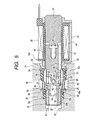
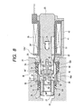
- Figs. 6 to 9 respectively show a second embodiment of a suction valve serving as an electromagnetic valve according to the present invention.
- Fig. 6 is a longitudinal section view of a suction valve, showing a state in which a suction valve is closed
- Fig. 7 is an enlarged view of the main portions of Fig. 6
- Fig. 8 is a section view of the suction valve corresponding to Fig. 6, showing a state in which a second valve mechanism is opened
- Fig. 9 is a longitudinal section view thereof corresponding to Fig. 6, showing a state in which a first valve mechanism is opened.
- a suction valve 12A' comprises a valve housing 22, a fixing core 23 to be fixed to the valve housing 22, a movable core 24' to be stored into the valve housing 22 in such a manner that it is disposed opposed to the fixing core 23, a first return spring 25 capable of applying a spring force for moving the movable core 24' apart from the fixing core 23, a coil 26, when energized, capable of applying an electromagnetic force for attracting the movable core 24' toward the fixing core 23 side, and first and second valve mechanisms 29', 30' to be interposed between the outlet port 27 of the valve housing 22 and inlet ports 28, 28, ---.
- the first valve mechanism 29' is composed of a movable seat member 44' which can be moved in the axial direction with respect to the movable core 24' in a limited range and is disposed opposed to the movable core 24' on the opposite of the fixing core 23, a second return spring 45 for energizing the movable seat member 44' in a direction where the movable seat member 44' is moved apart from the movable core 24', a rod-shaped first valve part 46' to be fixed to the movable core 24' by pressure insertion within a valve chamber 43 so formed within the valve housing 22 as to be in communication with the inlet ports 28, 28, ---, a first valve seat 47' formed in the movable seat member 44' in such a manner that the first valve part 46' can be seated on the first valve seat 47', and a first valve hole 48' formed in the movable seat member 44' in such a manner that one end of the valve hole 48' communicates with the outlet port 27 and the other end thereof is opened in the central portion of the
- a guide cylinder 49 which includes not only a plurality of communication holes 50, 50, --- but also an engaging flange 49a to be contactable and engageable with the movable seat member 44' from the opposite side of the movable core 24' so as to restrict the maximum distance between the movable core 24' and movable seat member 44'.
- the second valve mechanism 30' is composed of: a valve seat member 52 which forms the valve chamber 43 between the movable core 24' and itself and can be fitted with and fixed to the one-end side of the valve housing 22; a second valve seat 53 disposed on the valve seat member 52 in such a manner that it is coaxial with the first valve seat 47' and faces the valve chamber 43; a second valve hole 54 formed in the valve seat member 52 in such a manner that it is larger in diameter than the first valve hole 48', communicates with the outlet port 27 and is opened in the central portion of the second valve seat 53; and, a second valve part 55' disposed on the outer periphery of the movable seat member 44 in such a manner that it can be seated on the second valve seat 53.
- a cylindrical-shaped guide part 57' which can be slidably fitted into the second valve hole 54.
- annular-shaped passage 58' which, when the second valve part 55' is seated on the second valve seat 53, is cut off from the valve chamber 43 and, when the second valve part 55' is separated from the second valve seat 53, is allowed to communicate with the valve chamber 43; and, there are also. formed a plurality of communication passages 59' , --- which allow the annular-shaped passage 58' to communicate with the interior of the guide part 57.
- annular-shaped negative chamber 61 which, when the second valve part 55' is seated on the second valve seat 53, is situated between the second valve seat 53 and annular-shaped passage 58'; and, the pressure receive area A1 of the movable seat member 44', where the movable seat member 44'faces the annular-shaped vacuum pressure chamber 61 on the second valve seat 53 side, is set larger than the pressure receive area A2 thereof where it is faces the annular-shaped vacuum pressure chamber 61 on the annular-shaped passage 58' side.
- the movable core 24' is attracted to the fixing core 23 side. Due to this, the movable seat member 44', which is contacted and engaged with the engaging flange 49a of the guide cylinder 49, is also attracted to the fixing core 23 side. As a result of this, the first valve part 46' is separated from the first valve seat 47' to thereby open the first valve mechanism 29' and also the second valve part 55' is separated from the second valve seat 53 to thereby open the second valve mechanism 30', which allows the master cylinder M and first pump 10A to communicate with each other. In this state, the flow passage area between the inlet ports 28, 28, --- and outlet port 27 is relatively large and, therefore, a relatively large quantity of brake fluid is sucked from the master cylinder M to the first pump 10A.
- the movable core 24' is attracted toward the fixing core 23 side.
- the liquid pressure which presses the second valve part 55' of the movable seat member 44' against the second valve seat 53, is larger than the electromagnetic force that attracts the movable core 24' toward the fixing core 23 side.
- the second valve part 55' is seated on the second valve seat 53 to thereby close the second valve mechanism 30' but, due to the spring force of the second return spring 45 and the electromagnetic suction force of the coil 26, the first valve part 46' is separated from the first valve seat 47' to thereby open the first valve mechanism 29' . Therefore, the flow passage area between the inlet ports 28, 28, --- and outlet port 27 is relatively small, which reduces the quantity of the brake fluid to be supplied to the first pump 10A from the master cylinder M.
- the state, in which the first valve mechanism 29' is open and the second valve mechanism 30' is closed, can be maintained by the liquid pressure that is generated due to the pressure difference between the liquid pressure on the valve chamber 43 side and the liquid pressure on the outlet port 27 side smaller than the former liquid pressure to press the movable seat member 44' to the side where the second valve part 55' can be seated on the second valve seat 53.
- the sucking quantity of the brake fluid to the first pump 10A is relatively small, the above pressure difference is small, thereby raising a possibility that the valve closed state of the second valve mechanism 30' cannot be maintained.
- the annular-shaped vacuum pressure chamber 61 which is situated between the second valve seat 53 and annular-shaped passage 58' in a state where the second valve mechanism 30' is open, that is, in a state where the second valve part 55' is seated on the second valve seat 53, is formed between the inner surface of the second valve hole 54 and the outer surface of the movable seat member 44' in such a manner that the pressure receive area A1 where th movable seat member 44' faces the annular-shaped vacuum pressure chamber 61 on the second valve seat 53 side is larger than the pressure receive area A2 where the movable seat member 44' faces the annular-shaped vacuum pressure chamber 61 on the annular-shaped passage 58' side; and, in the movable seat member 44', there are formed the plurality of communication holed 62, --- which allow the annular-shaped vacuum pressure chamber 61 to communicate with the intermediate portion of the first valve hole 48'.
- the axial line of the movable seat member is prevented from inclining to thereby be able to maintain positively not only the sitting seal performance between the first valve part and first valve seat but also the sitting seal performance between the second valve part and second valve seat.
- a state, in which the first valve mechanism is open and the second valve mechanism is closed can be maintained more positively.
Applications Claiming Priority (4)
| Application Number | Priority Date | Filing Date | Title |
|---|---|---|---|
| JP2002140261 | 2002-05-15 | ||
| JP2002140261 | 2002-05-15 | ||
| JP2003105416A JP3819867B2 (ja) | 2002-05-15 | 2003-04-09 | 電磁弁 |
| JP2003105416 | 2003-04-09 |
Publications (3)
| Publication Number | Publication Date |
|---|---|
| EP1363057A2 true EP1363057A2 (de) | 2003-11-19 |
| EP1363057A3 EP1363057A3 (de) | 2004-01-02 |
| EP1363057B1 EP1363057B1 (de) | 2007-12-19 |
Family
ID=29272398
Family Applications (1)
| Application Number | Title | Priority Date | Filing Date |
|---|---|---|---|
| EP03009865A Expired - Fee Related EP1363057B1 (de) | 2002-05-15 | 2003-05-14 | Elektromagnetventil |
Country Status (4)
| Country | Link |
|---|---|
| US (1) | US6755390B2 (de) |
| EP (1) | EP1363057B1 (de) |
| JP (1) | JP3819867B2 (de) |
| DE (1) | DE60318151T2 (de) |
Cited By (8)
| Publication number | Priority date | Publication date | Assignee | Title |
|---|---|---|---|---|
| WO2007065776A1 (de) * | 2005-12-08 | 2007-06-14 | Robert Bosch Gmbh | Zweistufiges ventil zum steuern von fluiden |
| ES2326762A1 (es) * | 2005-09-19 | 2009-10-19 | Robert Bosch Gmbh | Instalacion de freno de vehiculo con una valvula. |
| WO2010029358A3 (en) * | 2008-09-09 | 2010-06-10 | Artemis Intelligent Power Limited | Valve assemblies |
| EP2338750A1 (de) * | 2009-12-22 | 2011-06-29 | Robert Bosch GmbH | Magnetventil sowie Fahrerassistenzeinrichtung |
| DE102008014099B4 (de) * | 2007-03-27 | 2012-08-23 | Mando Corp. | Ventil für ein Antiblockierbremssystem |
| CN104265973A (zh) * | 2014-08-10 | 2015-01-07 | 安徽省宁国新鼎汽车零部件有限公司 | 一种直动式电磁开关阀 |
| EP2942248A3 (de) * | 2014-03-28 | 2016-06-08 | Nissin Kogyo Co., Ltd. | Hydraulikbremsdruckerzeugungsvorrichtung |
| EP3246218A1 (de) * | 2010-02-03 | 2017-11-22 | Kelsey-Hayes Company | Elektromagnetventil |
Families Citing this family (37)
| Publication number | Priority date | Publication date | Assignee | Title |
|---|---|---|---|---|
| DE10252231A1 (de) * | 2002-04-26 | 2003-11-06 | Continental Teves Ag & Co Ohg | Elektromagnetventil, insbesondere für schlupfgeregelte Kraftfahrzeugbremsanlagen |
| JP2004340325A (ja) * | 2003-05-19 | 2004-12-02 | Hitachi Unisia Automotive Ltd | 電磁弁 |
| JP4010982B2 (ja) * | 2003-06-03 | 2007-11-21 | 日信工業株式会社 | 電磁弁 |
| JP4330943B2 (ja) * | 2003-06-30 | 2009-09-16 | 株式会社ジェイテクト | 水素ガス用高圧バルブ及び水素ガス用減圧装置 |
| JP2005030523A (ja) * | 2003-07-09 | 2005-02-03 | Nissin Kogyo Co Ltd | 電磁弁 |
| KR100978086B1 (ko) | 2004-12-10 | 2010-08-26 | 주식회사 만도 | 전자제어식 셔틀 밸브 |
| US7198249B2 (en) * | 2005-06-22 | 2007-04-03 | Continental Teves, Inc. | Electromagnetic shuttle valve |
| JP4744459B2 (ja) * | 2007-02-14 | 2011-08-10 | 日信工業株式会社 | 常開型電磁弁 |
| US20080197313A1 (en) * | 2007-02-16 | 2008-08-21 | Delphi Technologies, Inc. | Single piece actuator housing |
| US20080252140A1 (en) * | 2007-04-12 | 2008-10-16 | Mando Corporation | Valve for anti-lock brake system |
| DE102007031981B4 (de) * | 2007-07-10 | 2023-01-12 | Robert Bosch Gmbh | Magnetventil |
| EP2233806A1 (de) * | 2007-12-19 | 2010-09-29 | Toyooki Kogyo Co., Ltd. | Magnetvorsteuerventil zum öffnen und schliessen |
| JP2010223364A (ja) * | 2009-03-24 | 2010-10-07 | Hitachi Automotive Systems Ltd | 電磁弁 |
| JP5471734B2 (ja) * | 2009-06-03 | 2014-04-16 | トヨタ自動車株式会社 | 電磁弁 |
| DE102009046822A1 (de) * | 2009-11-18 | 2011-05-19 | Robert Bosch Gmbh | Schaltventil mit einem in einem Gehäuse bewegbaren Ventilelement |
| DE102010010187B4 (de) | 2010-03-03 | 2012-07-26 | Pierburg Gmbh | Elektromagnetventil |
| JP5409686B2 (ja) * | 2011-03-31 | 2014-02-05 | 日信工業株式会社 | 常開型電磁弁 |
| DE102011076556A1 (de) * | 2011-05-26 | 2012-11-29 | Continental Teves Ag & Co. Ohg | Elektromagnetventil, insbesondere für schlupfgeregelte Kraftfahrzeugbremsanlagen |
| KR101294674B1 (ko) * | 2011-11-02 | 2013-08-09 | 주식회사 만도 | 브레이크 시스템용 솔레노이드 밸브 |
| JP5644757B2 (ja) * | 2011-12-28 | 2014-12-24 | 株式会社日本自動車部品総合研究所 | 圧力制御装置 |
| CN103185164B (zh) * | 2011-12-31 | 2014-12-17 | 丹佛斯(天津)有限公司 | 电磁阀 |
| JP6156916B2 (ja) * | 2012-03-30 | 2017-07-05 | オートリブ日信ブレーキシステムジャパン株式会社 | 車両用ブレーキ液圧制御装置 |
| JP5773075B2 (ja) * | 2012-06-12 | 2015-09-02 | トヨタ自動車株式会社 | 常閉型電磁弁 |
| US9113591B2 (en) | 2012-06-18 | 2015-08-25 | Raven Industries, Inc. | Implement for adjustably metering an agricultural field input according to different frame sections |
| JP5733581B2 (ja) * | 2012-11-27 | 2015-06-10 | 株式会社デンソー | 高圧流体用電磁弁装置 |
| US11160204B2 (en) | 2013-03-15 | 2021-11-02 | Raven Industries, Inc. | Localized product injection system for an agricultural sprayer |
| US20150034180A1 (en) * | 2013-08-02 | 2015-02-05 | Continental Automotive Systems, Inc. | Tank pressure control solenoid with passive tank vacuum relief |
| DE102013223103A1 (de) * | 2013-09-23 | 2015-04-09 | Robert Bosch Gmbh | Ventil, insbesondere Magnetventil |
| US9945492B2 (en) * | 2013-10-15 | 2018-04-17 | Continental Automotive Systems, Inc. | Normally high solenoid assembly |
| US10173236B2 (en) | 2013-10-17 | 2019-01-08 | Raven Industries, Inc. | Nozzle control system and method |
| WO2015058091A1 (en) | 2013-10-17 | 2015-04-23 | Preheim John | Nozzle control system and method |
| CN104315229B (zh) * | 2014-10-20 | 2016-09-14 | 宁波市鄞州通力液压电器厂 | 电磁阀用电磁铁 |
| DE102015220358A1 (de) * | 2015-10-20 | 2017-04-20 | Continental Teves Ag & Co. Ohg | Elektromagnetventil |
| US11318923B2 (en) * | 2016-03-30 | 2022-05-03 | Autoliv Nissin Brake Systems Japan Co., Ltd. | Solenoid valve, vehicle brake hydraulic pressure control apparatus and solenoid valve fabrication method |
| DE102017209582A1 (de) * | 2016-09-23 | 2018-03-29 | Continental Teves Ag & Co. Ohg | Elektromagnetventil, insbesondere für schlupfgeregelte Kraftfahrzeugbremsanlagen |
| US11612160B2 (en) | 2019-10-04 | 2023-03-28 | Raven Industries, Inc. | Valve control system and method |
| CN114738495B (zh) * | 2021-01-08 | 2023-05-16 | 浙江盾安人工环境股份有限公司 | 电磁阀 |
Citations (1)
| Publication number | Priority date | Publication date | Assignee | Title |
|---|---|---|---|---|
| JP2000219118A (ja) | 1998-10-30 | 2000-08-08 | Kelsey Hayes Co | 車両ブレ―キ・システム用の流体圧制御ユニツト及びソレノイド供給弁 |
Family Cites Families (8)
| Publication number | Priority date | Publication date | Assignee | Title |
|---|---|---|---|---|
| JP3365151B2 (ja) * | 1994-08-05 | 2003-01-08 | アイシン精機株式会社 | 電磁弁 |
| JPH09508338A (ja) * | 1994-11-24 | 1997-08-26 | ローベルト ボツシユ ゲゼルシヤフト ミツト ベシユレンクテル ハフツング | 電磁的に制御可能な弁装置 |
| DE19529363A1 (de) * | 1995-08-10 | 1997-02-13 | Bosch Gmbh Robert | Steuerbares Ventil |
| DE19530899C2 (de) * | 1995-08-23 | 2003-08-21 | Bosch Gmbh Robert | Magnetventil, insbesondere für eine schlupfgeregelte, hydraulische Bremsanlage für Kraftfahrzeuge |
| JP3551221B2 (ja) * | 1996-09-10 | 2004-08-04 | 日清紡績株式会社 | 液圧ブレーキ装置における液圧制御弁装置 |
| DE19855667A1 (de) | 1997-12-05 | 1999-08-26 | Denso Corp | Magnetventil und Bremssystem mit einem Magnetventil |
| DE19757475C2 (de) * | 1997-12-23 | 1999-10-14 | Danfoss As | Servogesteuertes Magnetventil |
| US6435210B1 (en) * | 1998-03-31 | 2002-08-20 | Continental Teves Ag & Co. Ohg | Electromagnetic valve |
-
2003
- 2003-04-09 JP JP2003105416A patent/JP3819867B2/ja not_active Expired - Fee Related
- 2003-05-13 US US10/436,207 patent/US6755390B2/en not_active Expired - Lifetime
- 2003-05-14 EP EP03009865A patent/EP1363057B1/de not_active Expired - Fee Related
- 2003-05-14 DE DE60318151T patent/DE60318151T2/de not_active Expired - Lifetime
Patent Citations (1)
| Publication number | Priority date | Publication date | Assignee | Title |
|---|---|---|---|---|
| JP2000219118A (ja) | 1998-10-30 | 2000-08-08 | Kelsey Hayes Co | 車両ブレ―キ・システム用の流体圧制御ユニツト及びソレノイド供給弁 |
Cited By (16)
| Publication number | Priority date | Publication date | Assignee | Title |
|---|---|---|---|---|
| ES2326762A1 (es) * | 2005-09-19 | 2009-10-19 | Robert Bosch Gmbh | Instalacion de freno de vehiculo con una valvula. |
| DE102005058526B4 (de) | 2005-12-08 | 2019-06-19 | Robert Bosch Gmbh | Zweistufiges Ventil zum Steuern von Fluiden |
| CN101326392B (zh) * | 2005-12-08 | 2011-03-16 | 罗伯特·博世有限公司 | 用于控制流体的两级阀门 |
| US7954511B2 (en) | 2005-12-08 | 2011-06-07 | Robert Bosch Gmbh | Two-stage valve for controlling fluids |
| WO2007065776A1 (de) * | 2005-12-08 | 2007-06-14 | Robert Bosch Gmbh | Zweistufiges ventil zum steuern von fluiden |
| US8281802B2 (en) | 2007-03-27 | 2012-10-09 | Mando Corporation | Valve for anti-lock brake system |
| DE102008014099B4 (de) * | 2007-03-27 | 2012-08-23 | Mando Corp. | Ventil für ein Antiblockierbremssystem |
| US8602381B2 (en) | 2008-09-09 | 2013-12-10 | Artemis Intelligent Power Limited | Valve assemblies |
| US8602382B2 (en) | 2008-09-09 | 2013-12-10 | Artemis Intelligent Power Limited | Valve assemblies |
| WO2010029358A3 (en) * | 2008-09-09 | 2010-06-10 | Artemis Intelligent Power Limited | Valve assemblies |
| EP2338750A1 (de) * | 2009-12-22 | 2011-06-29 | Robert Bosch GmbH | Magnetventil sowie Fahrerassistenzeinrichtung |
| EP3246218A1 (de) * | 2010-02-03 | 2017-11-22 | Kelsey-Hayes Company | Elektromagnetventil |
| EP2942248A3 (de) * | 2014-03-28 | 2016-06-08 | Nissin Kogyo Co., Ltd. | Hydraulikbremsdruckerzeugungsvorrichtung |
| US9457784B2 (en) | 2014-03-28 | 2016-10-04 | Autoliv Nissin Brake Systems Japan Co., Ltd. | Brake hydraulic pressure generating device |
| CN104265973A (zh) * | 2014-08-10 | 2015-01-07 | 安徽省宁国新鼎汽车零部件有限公司 | 一种直动式电磁开关阀 |
| CN104265973B (zh) * | 2014-08-10 | 2016-09-14 | 安徽省宁国新鼎汽车零部件有限公司 | 一种直动式电磁开关阀 |
Also Published As
| Publication number | Publication date |
|---|---|
| JP3819867B2 (ja) | 2006-09-13 |
| US6755390B2 (en) | 2004-06-29 |
| EP1363057A3 (de) | 2004-01-02 |
| DE60318151D1 (de) | 2008-01-31 |
| DE60318151T2 (de) | 2008-12-04 |
| JP2004044783A (ja) | 2004-02-12 |
| EP1363057B1 (de) | 2007-12-19 |
| US20030213928A1 (en) | 2003-11-20 |
Similar Documents
| Publication | Publication Date | Title |
|---|---|---|
| EP1363057B1 (de) | Elektromagnetventil | |
| EP2022690B1 (de) | Fahrzeugbremsvorrichtung und behälter dafür | |
| JP2004155236A (ja) | 車両用液圧ブレーキ装置 | |
| US7144091B2 (en) | Brake apparatus with orifices for restricting brake fluid pressure pulsation | |
| US20160312912A1 (en) | Electromagnetic valve and brake unit | |
| EP0968894B1 (de) | Elektromagnetventil mit Druckbegrenzungsfunktion | |
| JPH11301442A (ja) | 車両用液圧ブレーキ装置 | |
| JP5957635B2 (ja) | ブレーキ液圧制御用のアクチュエータ | |
| JP4199253B2 (ja) | 電磁弁 | |
| JP4104482B2 (ja) | ブレーキ液圧制御装置用電磁弁 | |
| CN113056401B (zh) | 车辆用的制动系统的液压控制单元 | |
| JP3759470B2 (ja) | 電磁弁 | |
| JP3069991B2 (ja) | 車両のブレーキ液圧制御装置 | |
| JPH1053116A (ja) | 車輪ブレーキ液圧制御装置 | |
| JP5006243B2 (ja) | ブレーキ制御装置 | |
| JPH1067311A (ja) | 車輪ブレーキ液圧制御装置 | |
| JP2000043701A (ja) | 車両のブレーキ液圧制御装置 | |
| JP3819866B2 (ja) | 常閉型電磁弁 | |
| JP2001260841A (ja) | 電磁弁およびブレーキ装置 | |
| JP2000043699A (ja) | 車両のブレーキ液圧制御装置 | |
| JP2003042329A (ja) | 流体圧制御装置 | |
| JP2006182095A (ja) | ブレーキ液圧制御装置 | |
| JP2000006786A (ja) | 車両用ブレーキ液圧制御装置 | |
| JP3819803B2 (ja) | 電磁弁 | |
| JP3901361B2 (ja) | 車両のブレーキ液圧制御装置 |
Legal Events
| Date | Code | Title | Description |
|---|---|---|---|
| PUAI | Public reference made under article 153(3) epc to a published international application that has entered the european phase |
Free format text: ORIGINAL CODE: 0009012 |
|
| PUAL | Search report despatched |
Free format text: ORIGINAL CODE: 0009013 |
|
| AK | Designated contracting states |
Kind code of ref document: A2 Designated state(s): AT BE BG CH CY CZ DE DK EE ES FI FR GB GR HU IE IT LI LU MC NL PT RO SE SI SK TR |
|
| AX | Request for extension of the european patent |
Extension state: AL LT LV MK |
|
| AK | Designated contracting states |
Kind code of ref document: A3 Designated state(s): AT BE BG CH CY CZ DE DK EE ES FI FR GB GR HU IE IT LI LU MC NL PT RO SE SI SK TR |
|
| AX | Request for extension of the european patent |
Extension state: AL LT LV MK |
|
| RIC1 | Information provided on ipc code assigned before grant |
Ipc: 7B 60T 8/50 B Ipc: 7F 16K 31/06 A Ipc: 7B 60T 8/36 B |
|
| 17P | Request for examination filed |
Effective date: 20040317 |
|
| AKX | Designation fees paid |
Designated state(s): DE |
|
| 17Q | First examination report despatched |
Effective date: 20041005 |
|
| GRAP | Despatch of communication of intention to grant a patent |
Free format text: ORIGINAL CODE: EPIDOSNIGR1 |
|
| GRAS | Grant fee paid |
Free format text: ORIGINAL CODE: EPIDOSNIGR3 |
|
| GRAA | (expected) grant |
Free format text: ORIGINAL CODE: 0009210 |
|
| AK | Designated contracting states |
Kind code of ref document: B1 Designated state(s): DE |
|
| REF | Corresponds to: |
Ref document number: 60318151 Country of ref document: DE Date of ref document: 20080131 Kind code of ref document: P |
|
| PLBE | No opposition filed within time limit |
Free format text: ORIGINAL CODE: 0009261 |
|
| STAA | Information on the status of an ep patent application or granted ep patent |
Free format text: STATUS: NO OPPOSITION FILED WITHIN TIME LIMIT |
|
| 26N | No opposition filed |
Effective date: 20080922 |
|
| REG | Reference to a national code |
Ref country code: DE Ref legal event code: R082 Ref document number: 60318151 Country of ref document: DE Representative=s name: HOFFMANN - EITLE PATENT- UND RECHTSANWAELTE PA, DE Ref country code: DE Ref legal event code: R081 Ref document number: 60318151 Country of ref document: DE Owner name: AUTOLIV NISSIN BRAKE SYSTEMS JAPAN CO., LTD., , JP Free format text: FORMER OWNER: NISSIN KOGYO CO., LTD., UEDA, NAGANO, JP |
|
| PGFP | Annual fee paid to national office [announced via postgrant information from national office to epo] |
Ref country code: DE Payment date: 20190430 Year of fee payment: 17 |
|
| REG | Reference to a national code |
Ref country code: DE Ref legal event code: R119 Ref document number: 60318151 Country of ref document: DE |
|
| PG25 | Lapsed in a contracting state [announced via postgrant information from national office to epo] |
Ref country code: DE Free format text: LAPSE BECAUSE OF NON-PAYMENT OF DUE FEES Effective date: 20201201 |