EP1311771B1 - Radantriebseinheit - Google Patents
Radantriebseinheit Download PDFInfo
- Publication number
- EP1311771B1 EP1311771B1 EP01956907A EP01956907A EP1311771B1 EP 1311771 B1 EP1311771 B1 EP 1311771B1 EP 01956907 A EP01956907 A EP 01956907A EP 01956907 A EP01956907 A EP 01956907A EP 1311771 B1 EP1311771 B1 EP 1311771B1
- Authority
- EP
- European Patent Office
- Prior art keywords
- hub
- spline
- constant velocity
- velocity joint
- peripheral surface
- Prior art date
- Legal status (The legal status is an assumption and is not a legal conclusion. Google has not performed a legal analysis and makes no representation as to the accuracy of the status listed.)
- Expired - Lifetime
Links
Images

Classifications
-
- B—PERFORMING OPERATIONS; TRANSPORTING
- B60—VEHICLES IN GENERAL
- B60B—VEHICLE WHEELS; CASTORS; AXLES FOR WHEELS OR CASTORS; INCREASING WHEEL ADHESION
- B60B27/00—Hubs
- B60B27/0078—Hubs characterised by the fixation of bearings
- B60B27/0084—Hubs characterised by the fixation of bearings caulking to fix inner race
-
- F—MECHANICAL ENGINEERING; LIGHTING; HEATING; WEAPONS; BLASTING
- F16—ENGINEERING ELEMENTS AND UNITS; GENERAL MEASURES FOR PRODUCING AND MAINTAINING EFFECTIVE FUNCTIONING OF MACHINES OR INSTALLATIONS; THERMAL INSULATION IN GENERAL
- F16C—SHAFTS; FLEXIBLE SHAFTS; ELEMENTS OR CRANKSHAFT MECHANISMS; ROTARY BODIES OTHER THAN GEARING ELEMENTS; BEARINGS
- F16C19/00—Bearings with rolling contact, for exclusively rotary movement
- F16C19/02—Bearings with rolling contact, for exclusively rotary movement with bearing balls essentially of the same size in one or more circular rows
- F16C19/14—Bearings with rolling contact, for exclusively rotary movement with bearing balls essentially of the same size in one or more circular rows for both radial and axial load
- F16C19/18—Bearings with rolling contact, for exclusively rotary movement with bearing balls essentially of the same size in one or more circular rows for both radial and axial load with two or more rows of balls
-
- B—PERFORMING OPERATIONS; TRANSPORTING
- B60—VEHICLES IN GENERAL
- B60B—VEHICLE WHEELS; CASTORS; AXLES FOR WHEELS OR CASTORS; INCREASING WHEEL ADHESION
- B60B27/00—Hubs
-
- B—PERFORMING OPERATIONS; TRANSPORTING
- B60—VEHICLES IN GENERAL
- B60B—VEHICLE WHEELS; CASTORS; AXLES FOR WHEELS OR CASTORS; INCREASING WHEEL ADHESION
- B60B27/00—Hubs
- B60B27/0005—Hubs with ball bearings
-
- B—PERFORMING OPERATIONS; TRANSPORTING
- B60—VEHICLES IN GENERAL
- B60B—VEHICLE WHEELS; CASTORS; AXLES FOR WHEELS OR CASTORS; INCREASING WHEEL ADHESION
- B60B27/00—Hubs
- B60B27/0015—Hubs for driven wheels
- B60B27/0021—Hubs for driven wheels characterised by torque transmission means from drive axle
- B60B27/0026—Hubs for driven wheels characterised by torque transmission means from drive axle of the radial type, e.g. splined key
-
- B—PERFORMING OPERATIONS; TRANSPORTING
- B60—VEHICLES IN GENERAL
- B60B—VEHICLE WHEELS; CASTORS; AXLES FOR WHEELS OR CASTORS; INCREASING WHEEL ADHESION
- B60B27/00—Hubs
- B60B27/0015—Hubs for driven wheels
- B60B27/0036—Hubs for driven wheels comprising homokinetic joints
- B60B27/0042—Hubs for driven wheels comprising homokinetic joints characterised by the fixation of the homokinetic joint to the hub
-
- B—PERFORMING OPERATIONS; TRANSPORTING
- B60—VEHICLES IN GENERAL
- B60B—VEHICLE WHEELS; CASTORS; AXLES FOR WHEELS OR CASTORS; INCREASING WHEEL ADHESION
- B60B27/00—Hubs
- B60B27/0094—Hubs one or more of the bearing races are formed by the hub
-
- F—MECHANICAL ENGINEERING; LIGHTING; HEATING; WEAPONS; BLASTING
- F16—ENGINEERING ELEMENTS AND UNITS; GENERAL MEASURES FOR PRODUCING AND MAINTAINING EFFECTIVE FUNCTIONING OF MACHINES OR INSTALLATIONS; THERMAL INSULATION IN GENERAL
- F16C—SHAFTS; FLEXIBLE SHAFTS; ELEMENTS OR CRANKSHAFT MECHANISMS; ROTARY BODIES OTHER THAN GEARING ELEMENTS; BEARINGS
- F16C19/00—Bearings with rolling contact, for exclusively rotary movement
- F16C19/02—Bearings with rolling contact, for exclusively rotary movement with bearing balls essentially of the same size in one or more circular rows
- F16C19/14—Bearings with rolling contact, for exclusively rotary movement with bearing balls essentially of the same size in one or more circular rows for both radial and axial load
- F16C19/18—Bearings with rolling contact, for exclusively rotary movement with bearing balls essentially of the same size in one or more circular rows for both radial and axial load with two or more rows of balls
- F16C19/181—Bearings with rolling contact, for exclusively rotary movement with bearing balls essentially of the same size in one or more circular rows for both radial and axial load with two or more rows of balls with angular contact
- F16C19/183—Bearings with rolling contact, for exclusively rotary movement with bearing balls essentially of the same size in one or more circular rows for both radial and axial load with two or more rows of balls with angular contact with two rows at opposite angles
- F16C19/184—Bearings with rolling contact, for exclusively rotary movement with bearing balls essentially of the same size in one or more circular rows for both radial and axial load with two or more rows of balls with angular contact with two rows at opposite angles in O-arrangement
- F16C19/186—Bearings with rolling contact, for exclusively rotary movement with bearing balls essentially of the same size in one or more circular rows for both radial and axial load with two or more rows of balls with angular contact with two rows at opposite angles in O-arrangement with three raceways provided integrally on parts other than race rings, e.g. third generation hubs
-
- F—MECHANICAL ENGINEERING; LIGHTING; HEATING; WEAPONS; BLASTING
- F16—ENGINEERING ELEMENTS AND UNITS; GENERAL MEASURES FOR PRODUCING AND MAINTAINING EFFECTIVE FUNCTIONING OF MACHINES OR INSTALLATIONS; THERMAL INSULATION IN GENERAL
- F16C—SHAFTS; FLEXIBLE SHAFTS; ELEMENTS OR CRANKSHAFT MECHANISMS; ROTARY BODIES OTHER THAN GEARING ELEMENTS; BEARINGS
- F16C33/00—Parts of bearings; Special methods for making bearings or parts thereof
- F16C33/30—Parts of ball or roller bearings
- F16C33/58—Raceways; Race rings
- F16C33/64—Special methods of manufacture
-
- F—MECHANICAL ENGINEERING; LIGHTING; HEATING; WEAPONS; BLASTING
- F16—ENGINEERING ELEMENTS AND UNITS; GENERAL MEASURES FOR PRODUCING AND MAINTAINING EFFECTIVE FUNCTIONING OF MACHINES OR INSTALLATIONS; THERMAL INSULATION IN GENERAL
- F16C—SHAFTS; FLEXIBLE SHAFTS; ELEMENTS OR CRANKSHAFT MECHANISMS; ROTARY BODIES OTHER THAN GEARING ELEMENTS; BEARINGS
- F16C35/00—Rigid support of bearing units; Housings, e.g. caps, covers
- F16C35/04—Rigid support of bearing units; Housings, e.g. caps, covers in the case of ball or roller bearings
- F16C35/06—Mounting or dismounting of ball or roller bearings; Fixing them onto shaft or in housing
- F16C35/063—Fixing them on the shaft
- F16C35/0635—Fixing them on the shaft the bore of the inner ring being of special non-cylindrical shape which co-operates with a complementary shape on the shaft, e.g. teeth, polygonal sections
-
- F—MECHANICAL ENGINEERING; LIGHTING; HEATING; WEAPONS; BLASTING
- F16—ENGINEERING ELEMENTS AND UNITS; GENERAL MEASURES FOR PRODUCING AND MAINTAINING EFFECTIVE FUNCTIONING OF MACHINES OR INSTALLATIONS; THERMAL INSULATION IN GENERAL
- F16D—COUPLINGS FOR TRANSMITTING ROTATION; CLUTCHES; BRAKES
- F16D3/00—Yielding couplings, i.e. with means permitting movement between the connected parts during the drive
- F16D3/16—Universal joints in which flexibility is produced by means of pivots or sliding or rolling connecting parts
- F16D3/20—Universal joints in which flexibility is produced by means of pivots or sliding or rolling connecting parts one coupling part entering a sleeve of the other coupling part and connected thereto by sliding or rolling members
- F16D3/22—Universal joints in which flexibility is produced by means of pivots or sliding or rolling connecting parts one coupling part entering a sleeve of the other coupling part and connected thereto by sliding or rolling members the rolling members being balls, rollers, or the like, guided in grooves or sockets in both coupling parts
- F16D3/223—Universal joints in which flexibility is produced by means of pivots or sliding or rolling connecting parts one coupling part entering a sleeve of the other coupling part and connected thereto by sliding or rolling members the rolling members being balls, rollers, or the like, guided in grooves or sockets in both coupling parts the rolling members being guided in grooves in both coupling parts
-
- F—MECHANICAL ENGINEERING; LIGHTING; HEATING; WEAPONS; BLASTING
- F16—ENGINEERING ELEMENTS AND UNITS; GENERAL MEASURES FOR PRODUCING AND MAINTAINING EFFECTIVE FUNCTIONING OF MACHINES OR INSTALLATIONS; THERMAL INSULATION IN GENERAL
- F16C—SHAFTS; FLEXIBLE SHAFTS; ELEMENTS OR CRANKSHAFT MECHANISMS; ROTARY BODIES OTHER THAN GEARING ELEMENTS; BEARINGS
- F16C2226/00—Joining parts; Fastening; Assembling or mounting parts
- F16C2226/50—Positive connections
-
- F—MECHANICAL ENGINEERING; LIGHTING; HEATING; WEAPONS; BLASTING
- F16—ENGINEERING ELEMENTS AND UNITS; GENERAL MEASURES FOR PRODUCING AND MAINTAINING EFFECTIVE FUNCTIONING OF MACHINES OR INSTALLATIONS; THERMAL INSULATION IN GENERAL
- F16C—SHAFTS; FLEXIBLE SHAFTS; ELEMENTS OR CRANKSHAFT MECHANISMS; ROTARY BODIES OTHER THAN GEARING ELEMENTS; BEARINGS
- F16C2240/00—Specified values or numerical ranges of parameters; Relations between them
- F16C2240/40—Linear dimensions, e.g. length, radius, thickness, gap
- F16C2240/42—Groove sizes
-
- F—MECHANICAL ENGINEERING; LIGHTING; HEATING; WEAPONS; BLASTING
- F16—ENGINEERING ELEMENTS AND UNITS; GENERAL MEASURES FOR PRODUCING AND MAINTAINING EFFECTIVE FUNCTIONING OF MACHINES OR INSTALLATIONS; THERMAL INSULATION IN GENERAL
- F16C—SHAFTS; FLEXIBLE SHAFTS; ELEMENTS OR CRANKSHAFT MECHANISMS; ROTARY BODIES OTHER THAN GEARING ELEMENTS; BEARINGS
- F16C2326/00—Articles relating to transporting
- F16C2326/01—Parts of vehicles in general
- F16C2326/02—Wheel hubs or castors
-
- F—MECHANICAL ENGINEERING; LIGHTING; HEATING; WEAPONS; BLASTING
- F16—ENGINEERING ELEMENTS AND UNITS; GENERAL MEASURES FOR PRODUCING AND MAINTAINING EFFECTIVE FUNCTIONING OF MACHINES OR INSTALLATIONS; THERMAL INSULATION IN GENERAL
- F16D—COUPLINGS FOR TRANSMITTING ROTATION; CLUTCHES; BRAKES
- F16D3/00—Yielding couplings, i.e. with means permitting movement between the connected parts during the drive
- F16D3/16—Universal joints in which flexibility is produced by means of pivots or sliding or rolling connecting parts
- F16D3/20—Universal joints in which flexibility is produced by means of pivots or sliding or rolling connecting parts one coupling part entering a sleeve of the other coupling part and connected thereto by sliding or rolling members
- F16D3/22—Universal joints in which flexibility is produced by means of pivots or sliding or rolling connecting parts one coupling part entering a sleeve of the other coupling part and connected thereto by sliding or rolling members the rolling members being balls, rollers, or the like, guided in grooves or sockets in both coupling parts
- F16D3/223—Universal joints in which flexibility is produced by means of pivots or sliding or rolling connecting parts one coupling part entering a sleeve of the other coupling part and connected thereto by sliding or rolling members the rolling members being balls, rollers, or the like, guided in grooves or sockets in both coupling parts the rolling members being guided in grooves in both coupling parts
- F16D2003/22326—Attachments to the outer joint member, i.e. attachments to the exterior of the outer joint member or to the shaft of the outer joint member
-
- F—MECHANICAL ENGINEERING; LIGHTING; HEATING; WEAPONS; BLASTING
- F16—ENGINEERING ELEMENTS AND UNITS; GENERAL MEASURES FOR PRODUCING AND MAINTAINING EFFECTIVE FUNCTIONING OF MACHINES OR INSTALLATIONS; THERMAL INSULATION IN GENERAL
- F16D—COUPLINGS FOR TRANSMITTING ROTATION; CLUTCHES; BRAKES
- F16D2250/00—Manufacturing; Assembly
-
- F—MECHANICAL ENGINEERING; LIGHTING; HEATING; WEAPONS; BLASTING
- F16—ENGINEERING ELEMENTS AND UNITS; GENERAL MEASURES FOR PRODUCING AND MAINTAINING EFFECTIVE FUNCTIONING OF MACHINES OR INSTALLATIONS; THERMAL INSULATION IN GENERAL
- F16D—COUPLINGS FOR TRANSMITTING ROTATION; CLUTCHES; BRAKES
- F16D2300/00—Special features for couplings or clutches
- F16D2300/10—Surface characteristics; Details related to material surfaces
-
- Y—GENERAL TAGGING OF NEW TECHNOLOGICAL DEVELOPMENTS; GENERAL TAGGING OF CROSS-SECTIONAL TECHNOLOGIES SPANNING OVER SEVERAL SECTIONS OF THE IPC; TECHNICAL SUBJECTS COVERED BY FORMER USPC CROSS-REFERENCE ART COLLECTIONS [XRACs] AND DIGESTS
- Y02—TECHNOLOGIES OR APPLICATIONS FOR MITIGATION OR ADAPTATION AGAINST CLIMATE CHANGE
- Y02T—CLIMATE CHANGE MITIGATION TECHNOLOGIES RELATED TO TRANSPORTATION
- Y02T10/00—Road transport of goods or passengers
- Y02T10/80—Technologies aiming to reduce greenhouse gasses emissions common to all road transportation technologies
- Y02T10/86—Optimisation of rolling resistance, e.g. weight reduction
-
- Y—GENERAL TAGGING OF NEW TECHNOLOGICAL DEVELOPMENTS; GENERAL TAGGING OF CROSS-SECTIONAL TECHNOLOGIES SPANNING OVER SEVERAL SECTIONS OF THE IPC; TECHNICAL SUBJECTS COVERED BY FORMER USPC CROSS-REFERENCE ART COLLECTIONS [XRACs] AND DIGESTS
- Y10—TECHNICAL SUBJECTS COVERED BY FORMER USPC
- Y10S—TECHNICAL SUBJECTS COVERED BY FORMER USPC CROSS-REFERENCE ART COLLECTIONS [XRACs] AND DIGESTS
- Y10S464/00—Rotary shafts, gudgeons, housings, and flexible couplings for rotary shafts
- Y10S464/904—Homokinetic coupling
- Y10S464/906—Torque transmitted via radially spaced balls
Definitions
- the present invention relates to a wheel drive unit which is a combination of a wheel support rolling bearing unit, a constant velocity joint unit and a snap ring, and is used for rotatably supporting with respect to a suspension unit, a driven wheel ⁇ the front wheel of a FF vehicle (front engine, front drive wheel) the rear wheel of both a FR vehicle (front engine, rear drive wheel) and a RR vehicle (rear engine, rear drive wheel) and all wheels of a 4WD vehicle (four drive wheel) ⁇ supported on an independent suspension type suspension, and for rotationally driving the driven wheel.
- FF vehicle front engine, front drive wheel
- FR vehicle front engine, rear drive wheel
- RR vehicle rear engine, rear drive wheel
- FIG. 6 shows a typical bearing unit 3 for wheel drive wherein a rolling bearing unit 1 for wheel support and a constant velocity joint 2 are combined together for this kind of purpose.
- This rolling bearing unit for wheel support 1 is formed by rotatably supporting a hub 5 and an inner ring 6 on the inner diameter side of an outer ring 4 via a plurality of rolling elements 7.
- the outer ring 4 when connectingly secured to a knuckle 9 (refer to FIG. 7 mentioned below) constituting a suspension unit by means of a first flange 8 provided on the outer peripheral face thereof, does not rotate even at the time of use.
- a double row of outer ring raceways 10 is provided on the inner peripheral face of the outer ring 4, and the hub 5 and the inner ring 6 are rotatably supported on the inner diameter side, concentric with the outer ring 4.
- the hub 5 is provided with a second flange 11 for supporting the wheel, on a portion near an outer end (the end which is on the outside in a widthwise direction of the vehicle when fitted to the vehicle, namely, the left hand side of each figure including FIG. 6) of the outer peripheral face.
- the first inner ring raceway 12 is formed on a central portion of the outer peripheral face of the hub 5.
- an inner ring 6 with a second inner ring raceway 14 formed on an outer peripheral face thereof is externally secured to a small diameter step 13 formed on an inner end (the end which is on the middle side in a widthwise direction of the vehicle when fitted to the vehicle, namely the right hand side of each figure.).
- a spline bore 15 is provided, so that the hub 5 is formed in a hollow cylindrical shape.
- the constant velocity joint 2 has an outer ring 16 for constant velocity joint, an inner ring 17 for constant velocity joint and a spline shaft 18.
- the outer ring 16 for constant velocity joint and the spline shaft 18 constitute a drive member 19. That is, the spline shaft 18 is provided on an outer end of the drive member 19 and is freely engaged with the spline bore 15, and the outer ring 16 for constant velocity joint is provided on an inner end of the drive member 19.
- At a plurality of places on the inner peripheral face of the outer ring 16 for constant velocity joint around the circumferential direction are respectively formed outside engaging grooves 20 at right angles to the circumferential direction.
- a second spline bore 21 is formed at right angles to the circumferential direction in a center portion, and on the outer peripheral face, inside engaging grooves 22 are formed at right angles to the circumferential direction in portions coinciding with the outside engaging grooves 20.
- balls 23 are provided between each of the inside engaging grooves 22 and each of the outside engaging grooves 20 so as to be freely rotatable along each engaging groove 22 and 20, with the balls 23 being retained in a cage 24.
- portions between pairs of circumferentially adjacent outside engaging grooves 20 constitute cage guide faces 25.
- Each cage guide face 25 is positioned on a single spherical surface with a displacement center of the constant velocity joint 2 as the center thereof.
- this is similar to the case of a well know Rzeppa type or Birfield type constant velocity joint, and since this has no relevance to the gist of the present invention, detailed description is omitted.
- the spline shaft 18 is inserted into the spline bore 15 of the hub 5 from the inner side towards the outer side. Then a nut 27 is screwed onto an external thread portion 26 provided on an outer end portion of the spline shaft 18 projecting from an outer end face of the hub 5, and then by tightening, these are connected and secured together.
- a nut 27 is screwed onto an external thread portion 26 provided on an outer end portion of the spline shaft 18 projecting from an outer end face of the hub 5, and then by tightening, these are connected and secured together.
- the inner end face of the inner ring 6 is abutted against the outer end face of the outer ring 16 for constant velocity joint, there is no displacement of the inner ring 6 in a direction to come off from the small diameter step portion 13.
- an appropriate pre-load is applied to each of the rolling elements 7.
- a male spline portion 29 provided on an outer end of a drive shaft 28 is spline engaged with a second spline bore 21 provided in a central portion of the inner ring 17 for constant velocity joint.
- a snap ring 37 which is stoppingly engaged in an engaging groove 30 formed around the whole periphery in the outer peripheral face at the outer end of the male spline portion 29, is engaged with an engaging step portion 32 formed in an opening rim at the outer end of the second spline bore 21, thereby preventing the male spline portion 29 from coming out from the second spline bore 21.
- the inner end of the drive shaft 28 is connectingly secured to the center of a trunnion 34 (refer to FIG. 1 showing a first example of an embodiment of the present invention) of a tripod type constant velocity joint 33 provided on an output shaft of a differential gear.
- the weight is increased because the rolling bearing unit 1 for wheel support and the constant velocity joint 2 are connectingly secured based on the threaded and tightened engagement between the male thread portion 29 and the nut 27. That is, providing the external thread portion 26 on the spline shaft 18 of the constant velocity joint 2 requires lengthening of the spline shaft 18, and the nut 27 also becomes necessary. Therefore the axial dimension and the weight of the bearing unit 3 for wheel drive are increased by the male thread portion 26 and the nut 27.
- FIG. 7 a bearing unit 3a for wheel drive that enables shortening of the axial dimension and a reduction in weight, by connectingly securing the rolling bearing unit for wheel support and the constant velocity joint by a relatively simple construction.
- a hub 5 is rotatably supported on the inside of an outer ring 4 secured to a knuckle 9, by rolling elements 7 arranged in a double row.
- a spline shaft 18 of a drive member 19a is spline engaged with a spline bore 15 formed in a central portion of the hub 5.
- An engaging portion 35 is formed in an outer end surface of the spline shaft 18 for engaging with a tool for drawing the spline shaft 18 into the spline bore 15. Furthermore, the spline shaft 18 is prevented from coming off from the hub 5 by a snap ring 31 which is stoppingly engaged in an engaging groove 36 formed in an outer peripheral face of the spline shaft 18 at a portion close to its tip end (outer end). In this condition, an resilient ring 34 is resiliently compressed between the hub 5 and the outer ring 16 for constant velocity joint of the drive member 19a, thereby effecting play prevention of the spline shaft 18 and the hub 5. In the case of the second example of this kind of conventional construction, to the extent that connection of the rolling bearing unit 1a for wheel support and the constant velocity joint 2a is performed by the snap ring 31, an overall smaller size and lighter weight for the bearing unit 3a for wheel drive is achieved.
- a rolling bearing unit 1b for wheel support constituting the bearing unit 3b for wheel drive has a hollow hub 5a such that a constant velocity joint outer ring 16a constituting a constant velocity joint 2b corresponding to the drive member described in the claims, is connected to an inner end of the hollow hub 5a via a spacer 38.
- an inner diameter side female spline portion 39 is formed on the inner peripheral surface of the spacer 38, and an outer diameter side male spline portion 40 corresponding to the first spline portion described in the claims is formed on the outer peripheral surface of the spacer 38.
- This spacer 38 is assembled on an outer peripheral face at the inner end of the hub 5a, with an inner diameter side male spline portion 41 formed on an outer peripheral surface thereof in spline engagement without play with the inner diameter side female spline portion 39.
- an outer diameter side female spline portion 43 corresponding to the second spline portion described in the claims, which is formed on the inner peripheral face at the outer end of the outer ring 16a for constant velocity joint is spline engaged with an outer diameter side male spline portion 40. That is, the outer diameter side female spline portion 43 is formed in an inner peripheral face at the outer end of the outer ring 16a for constant velocity joint. Moreover, as mentioned above, the outer diameter side female spline portion 43 is spline engaged with the outer diameter side male spline portion 40 formed on the outer peripheral surface of the spacer 38.
- a snap ring 31a spans between the outer diameter side female spline portion 43 and the outer diameter side male spline portion 40 which are spline engaged with each other as described above, so that the outer ring 16a for constant velocity joint cannot separate from the spacer 38. That is, the snap ring 31a is formed in a semi-circle annular shape and made to span between an inside engaging groove 44 corresponding to a first connecting portion described in the claims, which is formed around the whole periphery in the outer peripheral surface of the spacer 38, and an outside engaging groove 45 corresponding to a second connecting portion described in the claims, which is formed around the whole periphery in the inner peripheral surface at the outer end of the outer ring 16a for constant velocity joint. Hence the outer ring 16a for constant velocity joint and the spacer 38 cannot be displaced from each other in the axial direction.
- the spline shaft 18 can be omitted from the second example of the conventional construction shown in FIG. 7, and to that extent, the cost and weight can be further reduced.
- the present invention was invented taking this situation into consideration, in order to optimize the properties of each constituent element so as to ensure durability of the wheel drive unit.
- the present invention provides a wheel drive unit as defined by claim 4 and, in particular, as defined by claim 1, i.e. comprising a rolling bearing unit for vehicle wheel, a constant velocity joint unit and a snap ring, the constant velocity joint unit comprising a first constant velocity joint having an output portion and a input portion connected to an output portion of a differential gear, a transmission shaft having an output end and an input end connected to the output portion of the first constant velocity joint, and a second constant velocity joint having an output portion and an input portion connected to the output end of the transmission shaft, the rolling bearing unit for vehicle wheel comprising an outer ring having an inner peripheral surface formed with outer ring raceways and being not rotatable during use, a hollow hub having an outer peripheral surface formed with an flange for supporting a vehicle wheel near the outer end thereof, with a first inner ring raceway at the middle portion thereof, and with a small diameter stepped portion formed near the inner end thereof, an inner ring having an outer peripheral surface formed with a second inner ring raceway and fitted onto the small diameter
- the wheel drive unit of the present invention comprises a rolling bearing unit for wheel support, a constant velocity joint unit and a snap ring.
- the constant velocity joint unit has a first constant velocity joint for connecting an input portion thereof to an output portion of a differential gear, a transmission shaft with an input side end portion thereof connected to an output portion of the first constant velocity joint, and a second constant velocity joint with an input portion thereof to an output side end portion of the transmission shaft connected.
- the rolling bearing unit for wheel support has an outer ring, a hollow hub, rolling elements and a first spline portion.
- the outer ring has a double row of outer ring raceways on an inner peripheral face thereof and does not rotate at the time of use.
- the hub is provided with a flange for supporting a vehicle wheel, on a part near an outer end of an outer peripheral face thereof, and a first inner ring raceway on a central portion thereof.
- An inner ring with a second inner ring raceway formed on an outer peripheral face thereof is externally secured to a small diameter step portion formed on a part of the outer peripheral face near the inner end thereof, and the coming off of the inner ring from the small diameter step portion is prevented by a crimped portion formed by plastic deformation of the inner end portion in a radially outward direction.
- the rolling elements are respectively provided severally so as to be freely rotatable between each of the outer ring raceways and each of the first and second inner ring raceways.
- the first spline portion is provided on the hub or on a part of a peripheral face of a member connectingly secured to the hub.
- the second constant velocity joint incorporates a drive member with a second spline portion for spline engagement with the first spine portion provided on an outer end peripheral face thereof, and an inner end portion serving as a constant velocity joint outer ring constituting the second constant velocity joint.
- the snap ring spans between a first engaging portion provided on the hub or a part of the periphery of a member connectingly secured to the hub, and a second engaging portion provided on a peripheral face at the outer end of the drive member, thereby preventing the separation of the connection between the first spline portion and the second spline portion.
- the properties of each constituent element can be such as to correspond optimally to the stress etc. applied to each member, the durability can be sufficiently ensured.
- the rolling fatigue life of this first inner ring raceway portion is improved. Furthermore, because the stepped face portion existing at the innermost end of the small diameter step portion is quench-hardened, the thrust load which this stepped face portion bears can be made sufficiently large. Accordingly, when the crimped portion is formed on the inner end portion of the hub in a condition with the outer end face of the inner ring abutted against the stepped face portion, so that the inner ring is secured to the hub, there is no plastic deformation of the stepped face portion. As a result, by clamping the inner ring with the crimped portion an appropriate pre-load can be applied to each rolling element.
- the inner peripheral face of the hub positioned on the inner diameter side of the quench-hardened portion corresponding to the small diameter step portion, is not quench-hardened, and therefore there is no quench-hardened portion penetrating from the inner peripheral face of the hub to the outer peripheral face thereof. Therefore, the existence of a partially brittle portion in the hub is prevented. Hence damage such as cracking occurring in the hub during the process of quench-hardening of the hub, or lowering of the shock resistance of the hub can be prevented.
- the portion of the hub to be crimped is not quench-hardened, when forming the crimped portion in order to connectingly secure the inner ring to the hub, damage such as cracking does not occur at this crimped portion, and a high quality crimped portion can thus be formed. Furthermore, at one portion of the peripheral face of at least one of the hub or a member connectingly secured to the hub, and the drive member, which is formed with the engaging groove being the first connecting portion or the second connecting portion, is not quench-hardened. Therefore, damage such as cracking due to heat treatment does not occur in the portion where the abovementioned engaging groove is formed and where distortion can easily occur with heat treatment.
- the rolling fatigue life of the outer engaging groove portion is improved with the quench-hardening of the outer engaging groove portion. Furthermore, of the inner peripheral face of the outer ring for constant velocity joint, since the cage guide face portion existing between the circumferentially adjacent outer engaging groove pairs is quench-hardened, the wear resistance and seizure resistance of the cage guide face portion which rubbingly contacts with the outer peripheral face of the cage constituting the constant velocity joint can be improved.
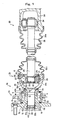
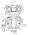
- FIG. 1 to FIG. 3 show a first example of an embodiment of the present invention corresponding to claims of the invention.
- a characteristic of the present invention is the point that with a construction enabling easy connection of a rolling bearing unit 1c for wheel support constituting a drive unit for vehicle wheel, to a constant velocity joint 2c, being a second constant velocity joint described in the claims, the reliability and durability of the rolling bearing unit 1c for wheel support and the constant velocity joint 2c is ensured.
- Part of the basic construction of a bearing unit for wheel drive formed by combining the rolling bearing unit 1c for wheel support and the constant velocity joint 2c has many portions common to some of the conventional constructions shown in the FIG. 6 to FIG. 8. Therefore, equivalent portions are denoted by the like reference symbols, and repeated explanation is omitted or made briefly.
- a description centered on the different points between the characteristic portions of the present invention and those of the aforementioned conventional construction.
- a hub 5b constituting the rolling bearing unit 1c for wheel support is prepared to an approximate shape by hot forging a material such as S53CG, and is then processed to a desired shape and properties by subjecting to machining, induction hardening, grinding and superfinishing.
- machining, induction hardening, grinding and superfinishing Regard the part subjected to induction hardening, this will be explained in detail later, but of the surface of the hub 5b, the surface hardness of the portion subjected to this induction hardening is H R C 58 ⁇ 64, and the effective thickness of the hardened layer is around 1.5 ⁇ 3 mm.
- This inner ring 6 is prepared to an approximate shape by hot forging a material such as SUJ2, and then processed to a desired shape and properties by subjecting to machining, dip quenching, grinding and superfinishing.
- the hardness is H R C60 ⁇ 64.
- a crimped portion 42a is formed on an inner end portion of the hub 5b.
- an engaging groove 47 corresponding to the second connecting portion described in the claims, is formed around the entire periphery in the outer peripheral face at the outer end of the spline shaft 18 constituting the drive member 19b incorporated into the constant velocity joint 2c.
- the drive member 19b including the spline shaft 18 is prepared to an approximate shape by hot forging a material such as S55CG, and is then processed to a desired shape and properties by subjecting to machining, induction hardening, grinding and superfinishing.
- the surface hardness of the portion subjected to this induction hardening is H R C 58 ⁇ 64.
- the effective thickness of the hardened layer this differs depending on location, but is around 2 ⁇ 7.5 mm.
- the thickness is around 2 ⁇ 4 mm.
- the outer peripheral face portion of the spline shaft 18 is not subjected to grinding and hence has a thickness of around 5 ⁇ 7.5 mm.
- the snap ring 31b is formed by bending into a semi-circle annular shape a material with a circular cross-section such as SWPA and SWPB, and in a free state has resilience in the direction for expanding the diameter. Moreover, the hardness is H R C 48 ⁇ 54.
- this snap ring 31b are, as mentioned below, fixed by design so that the allowable stress is not exceeded when passing through the spline bore 15 in order to assemble the bearing unit 3c for wheel drive, and at the time of use.
- the diameter of the cross-section of the snap ring 31b can be increased as the pitch circle diameter of the spline is increased.
- the pitch circle diameter is 24 mm
- the diameter of the cross-section is made 1.4 mm.
- the pitch circle diameter is 30 mm
- the diameter of the cross-section is made 1.7 mm.
- FIG. 3 shows one example of the dimensions of the installation portion for the case where the diameter of this cross-section is 1.7 mm.
- the diameter of the cross-section is not limited to 1.7 mm, and can be appropriately set within a range of for example 1.7 ⁇ 2.5 mm.
- the part nearer the outer end opening than the engaging step portion 32a is formed with no female spline teeth and with a simple cylindrical surface. That is, the central bore of the hub 5b is divided into the spline bore 15 and a simple circular bore 48 with a larger diameter than the spline bore 15, with the engaging step portion 32a as a the border therebetween. Furthermore, the snap ring 31b is fitted into the engaging groove 47 prior to insertion of the spline shaft 18 into the spline bore 15. When the spline shaft 18 is inserted into the spline bore 15, the snap ring 31b passes through inside the spline bore 15 with the diameter resiliently contracted. Then, in the condition with the snap ring 31b matching with the engaging step portion 32a, the diameter thereof is resiliently restored, and similarly to above, the snap ring 31b is spanned between the engaging step portion 32a and the engaging groove 47.
- a seal ring 51 is externally fitted to an outer peripheral face of a shoulder 50 formed on a base end of the outer ring 16b for constant velocity joint constituting the drive member 19b.
- This seal ring 51 in a condition externally secured to the shoulder 50, is resiliently compressed between the inside face of the crimped portion 42a and the outside face of the outer ring 16b for constant velocity joint, thus closing off a gap between the crimped portion 42a and the outer ring 16b for constant velocity joint.
- a proviso is that the interference of the seal lip of the seal ring 51 in a condition with the size of the gap 53 a maximum, is greater than the settling amount of the seal ring 51 with use over a long period. The reason for this is in order to maintain the resilient compression condition of the seal ring 51 between the inside face of the crimped portion 42a and the outer end face of the outer ring 16b for constant velocity joint, even in the case where the seal ring 51 has settled.
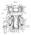
- the portion shown by a diagonal grid hatching in FIG. 2 on a part of the surface of the hub 5b and drive member 19b is quench-hardened by induction quench-hardening.
- the intermediate portion excluding the axially opposite ends is quench-hardened.
- the quench- hardened portion related to the outer peripheral face of this hub 5b describing from the outside, the base end portion of the second flange 11 for supporting the wheel on this hub 5b is quench-hardened.
- This portion is hardened in order to improve the bending rigidity of the second flange 11, and so that the second flange 11 does not bendingly deform in spite of the moment applied from the vehicle wheel at the time of traveling, and at the same time to suppress wear accompanying sliding of a seal lip constituting a seal ring 54 which is secured to the outer end of an outer ring 4.
- first inner ring raceway 12 and a stepped face 46 existing at the innermost end of the small diameter step portion 13 and abutted against the outer end face of the inner ring 6 is quench-hardened.
- the portion of first inner ring raceway 12 is quench-hardened to improve the rolling fatigue life of the portion of first inner ring raceway 12.
- the portion of the stepped face 46 existing at the innermost end of the small diameter step portion 13 is quench-hardened to sufficiently increase the thrust load that this portion of the stepped face 46 can bear.
- the engaging step portion 32a and the portion near the engaging step portion 32a is hardened by induction quench-hardening.
- the induction quench-hardening of these portions is performed in order to prevent plastic deformation in the case where the engaging step portion 32a is strongly pressed by the snap ring 31b, and to reliably prevent the engagement between the engaging step portion 32a and the snap ring 31b from being separated from each other.
- the quench-hardened layer of the portion of engaging step portion 32a and the quench-hardened layer of the portion of stepped face 46 are not connected to each other.
- the quench-hardened layer does not penetrate through both the inner and the outer peripheral faces of the hub 5b.
- the shock resistance (tenacity) of the hub 5b can be ensured.
- the engaging step portion provided on the inner peripheral face of the hub and the stepped face provided on the outer peripheral face are adjacent to each other, when the quench-hardened layer is formed in the engaging step portion, there is the possibility for the quench-hardened layer to penetrate through both the inner and outer peripheral faces of the hub. In such a case, it becomes difficult to ensure the shock resistance of the hub. Therefore, no quench-hardened layer is formed in the engaging step portion (no quench-hardening is conducted).
- the outer peripheral face from the base end to the middle portion of the spline shaft 18 is quench-hardened. Further, in the example shown in the figure, a portion of the outer end face abutted against the inner diameter side half of the seal ring 51 of the outer ring 16b for constant velocity joint is also quench-hardened.
- the base end of the spline shaft 18 is quench-hardened to ensure the fatigue strength of this base end with respect to the bending moment repeatedly applied to the spline shaft 18 at the time of traveling.
- the middle portion of the spline shaft 18 is quench-hardened to suppress plastic deformation and wear of a male spline portion 29 formed on the outer peripheral face of the spline shaft 18.
- the outer end face of the outer ring 16b for constant velocity joint is quench-hardened to suppress deformation of the bearing face of the seal ring 51 and thus ensure the seal performance due to the seal ring 51. Furthermore, in the example shown in the figure, because the outer end portion of the outer ring 16b for constant velocity joint is made thin in order to lighten the outer ring 16b for constant velocity joint, this portion is also quench-hardened for strength retention of this portion.
- the portions of each outside engaging groove 20 and the cage guide face 25 existing between each pair of the circumferentially adjacent outside engaging grooves 20 are quench-hardened.
- the portion of outside engaging groove 20 are quench-hardened in order to improve the rolling fatigue life of the portion of outside engaging groove 20.
- the portion of cage guide face 25 is quench-hardened in order to improve the wear resistance and seizure resistance of the portion of cage guide face 25 which comes rubbingly in contact with the outer peripheral face of the cage 24 constituting the constant velocity joint 2c. Consequently, the portion of the inner peripheral face of the outer ring 16b for constant velocity joint where the outside engaging grooves 20 and the cage guide faces 25 are formed, is quench-hardened around the entire periphery.
- the inner peripheral face of the hub 5b excluding the portion corresponding to the engaging step portion 32a, is not quench-hardened.
- the portion positioned on the inner diameter side of the quench-hardened portion corresponding to the small diameter step portion 13 is not quench-hardened.
- the quench-hardened portion does not penetrate through from the inner peripheral face of the hub 5b to the outer peripheral face thereof.
- the quench-hardened layer at this portion may penetrate through from the inner peripheral face of the hub 5b to the outer peripheral face thereof.
- the quench-hardened layer although being difficult to deform, is brittle with poor toughness, and is easily broken due to the impact load. Therefore, it is not desirable for the quench-hardened layer to penetrate through the inner and outer peripheral faces of the hub 5b.
- the partial existence of brittle portions is prevented, so that it is possible to prevent the occurrence of damage such as cracking in the hub 5b or a drop in impact resistance of the hub 5b accompanying the quench-hardening process for the hub 5b.
- the cylindrical portion for forming the crimped portion 42a is not quench-hardened but is left as it is so as to form a high quality crimped portion 42a without the occurrence of damage such as cracking in the crimped portion 42a, when forming the crimped portion 42a in order to connectingly secure the inner ring 6 to the hub 5b.
- the portion at the tip end of the spline shaft 18 in which the engaging groove 47 is formed is not quench-hardened but is left as it is so as to prevent damage such as cracks developing from small notches, due to heat treatment.
- the wheel drive unit of the present example is formed by combining the bearing unit 3c for wheel drive constructed as mentioned above, with a drive shaft 28, as shown in FIG. 1, and a constant velocity joint 33 of the tripod type, being the first constant velocity joint described in the claims. That is, a male spline portion 29 provided on the outer end of the drive shaft 28 is spline engaged with the second spline bore 21 provided at the center of the inner ring 17 for constant velocity joint constituting the bearing unit 3c for wheel drive.
- the snap ring 37 stoppingly engaged in the engaging groove 30 formed around the whole periphery of the outer peripheral face at the outer end of the male spline portion 29, is connected to the engaging step portion 32 formed on the opening rim at the outer end of the second spline bore 21, thereby preventing the male spline portion 29 from coming out from the second spline bore 21.
- the inner end of the drive shaft 28 is connectingly secured to the center of the trunnion 34 of the constant velocity joint 33 provided on the output shaft of the differential gear.
- the inner end of the drive shaft 28 is connected to the center of the trunnion 34 constituting the constant velocity joint 33 provided on the end of the output shaft of the differential gear (not shown in the figure). Furthermore, a pair of boots 56a and 56b for preventing grease leaks and preventing the ingress of foreign matter are respectively secured between the outer peripheral faces at the intermediate portion of the drive shaft 28 and the peripheral face at the outer end of the housing 55 constituting the constant velocity joint 33 and the peripheral face at the inner end of the outer ring 16b for constant velocity joint. Each of these boots 56a and 56b is formed in an overall cylindrical shape with the intermediate portion formed in a bellows shape.
- connection between the rolling bearing unit 1c for wheel support and the constant velocity joint 2c which constitute the wheel drive bearing unit 3c is performed by the snap ring 31b. Therefore, simplification of the assembly operation is devised in a similar manner to the case of the beforementioned second example of the conventional construction shown in FIG. 7.
- the wheel drive unit of the present invention because as mentioned before, each constituent element of the bearing unit 3c for wheel drive is regulated for optimum properties, the durability of the bearing unit 3c for wheel drive can be ensured.
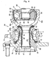
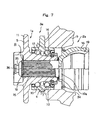
- FIG. 4 shows a second example of an embodiment of the present invention.
- a radially wide stepped face 57 is formed on an opening rim at the outer end of a spline bore 15 at an intermediate part of a hub 5c constituting a wheel drive bearing unit 3d.
- This stepped face 57 corresponds to the first engaging portion described in the claims.
- a snap ring 31c is provided to have the inner periphery thereof stoppingly engaged in an engaging groove 47 being the second engaging portion, formed in a tip end of a spline shaft 18, and the half on the outer diameter side of the snap ring 31c is engaged with the stepped face 57, thereby preventing the spline shaft 18 from coming out from the spline bore 15.
- a radially wide ring in a semi-circle annular shape with a discontinuous portion provided at one circumferential location is used for the snap ring 31c. Therefore, the contact area of the snap ring 31c and the stepped face 57 is large so that the contact face pressure can be reduced. Consequently, in the case of the present example, even if this stepped face 57 is not quench-hardened in particular, plastic deformation of the stepped face 57 can be prevented.
- the construction and operation of other parts is substantially the same as for the case of the first example.
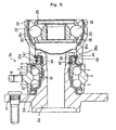
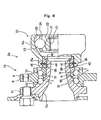
- FIG. 5 shows a third example of an embodiment of the present invention.
- This example shows the case where the present invention is applied to the construction of the third example of the conventional construction shown in FIG. 8.
- An outer ring 16c for constant velocity joint constituting a constant velocity joint 2d, and corresponding to the drive member described in the claims, is connected to an inner end of a hollow hub 5d constituting a bearing unit 3e for wheel drive, via a spacer 38a serving as a connecting member.
- the inner peripheral face formed with a female spline portion 39 on the inner diameter side is quench-hardened along the entire axial length
- the outer peripheral face formed with a male spline portion 40 on the outer diameter side corresponding to the first spline portion described in the claims, excluding an inside engaging groove 44 corresponding to the first engaging portion described in the claims is quench-hardened.
- the female spline portion 43 on the outer diameter side corresponding to the second spline, formed on the inner peripheral face at the outer end of the constant velocity joint outer ring 16c corresponding to the drive member described in the claims, excluding an outside engaging groove 45 corresponding to the second engaging portion is also quench-hardened.
- both of the spline portions may be parallel splines constructed from spline teeth having axially parallel side faces, or may be tapered splines constructed from spline teeth where each of the spline teeth has side faces slightly inclined in mutually opposite directions with respect to the axial direction.
- these may be twisted splines where only the female spline portion is a parallel spline, and opposite side faces of the spline portions constituting the male spline are slightly inclined in the same direction with respect to the axial direction.
- the portions such as the engaging groove formed in the member provided with the male spline is not quench-hardened, and is left as they are. That is, all or part of the male spline portion formed in the member provided with the male spline portion, is quench-hardened, but in any case, the portions such the engaging groove are left as they are.
- the female spline portion it is optional as to whether or not this is quench-hardened, and in the case where this is quench-hardened, the range over which this is quench-hardened can be freely selected.
- the connecting installation portion such as the engaging step portion provided on the inner peripheral face of the member provided with the female spline portion, where damage such as cracking due to heat treatment does not develop easily compared to the engaging groove.
- the engaging step portion and the like are also not quench-hardened.
- the engaging step portion and the like may or may not be quench-hardened.
- the engaging step portion and the like may be subjected to quench-hardening treatment, or only this engaging step portion and the like may be not subjected to quench-hardening treatment.
- the quench-hardening of the outer ring 4 constituting the rolling bearing unit for wheel support because this is similar to the case of the conventional construction, diagrams and explanation of the quench-hardened portions are omitted.
- the surface roughness of both of the male and female spline portions this can be established by design, but, for example, regarding the male spline, by making it with a rolling process, the surface roughness can be regulated to around 3.2S. Furthermore, regarding the female spline portion, by making it with a broach process, the surface roughness can be regulated to around Ra 6.3.
- the present invention is constructed and operates as described above, thus enabling a wheel drive unit with superior durability to be realized at a low cost.
Landscapes
- Engineering & Computer Science (AREA)
- Mechanical Engineering (AREA)
- General Engineering & Computer Science (AREA)
- Manufacturing & Machinery (AREA)
- Rolling Contact Bearings (AREA)
- Braking Arrangements (AREA)
- Mounting Of Bearings Or Others (AREA)
- Vehicle Body Suspensions (AREA)
Claims (4)
- Rad-Antriebseinheit umfassend eine Wälzlagereinheit für ein Fahrzeugrad, eine Gleichlauf-Gelenkeinheit und einen Einschnappring,
wobei die Gleichlauf-Gelenkeinheit ein erstes Gleichlaufgelenk mit einem Abtriebsabschnitt und einem an einem Abtriebsabschnitt eines Differentialgetriebes angeschlossenen Antriebsabschnitt, eine Übertragungswelle mit einem Abtriebsende und einem Antriebsende, welche an dem Abtriebsabschnitt des ersten Gleichlaufgelenks angeschlossen ist, und ein zweites Gleichlaufgelenk mit einem Abtriebsabschnitt und einem an dem Abtriebsende der Übertragungswelle angeschlossenen Antriebsabschnitt umfasst,
wobei die Wälzlagereinheit für ein Fahrzeugrad einen Außenring mit einer inneren Umfangsoberfläche, welche mit Außenringlaufflächen ausgebildet ist und während der Verwendung nicht drehbar ist, eine hohle Nabe mit einer äußeren Umfangsoberfläche, welche mit einem Flansch zum Tragen eines Fahrzeugrades in der Nähe eines äußeren Endes desselben ausgebildet ist, mit einer ersten Innenringlauffläche an einem mittleren Abschnitt desselben, und mit einem gestuften Abschnitt kleinen Durchmessers, welcher nahe des inneren Endes desselben ausgebildet ist, einem Innenring mit einer äußeren Umfangsoberfläche, welcher mit einer zweiten Innenringlauffläche ausgebildet ist und auf den gestuften Abschnitt kleinen Durchmessers der Nabe aufgepasst ist, wobei das innere Ende der Nabe radial nach außen plastisch deformiert ist, um einen gequetschten Abschnitt auszubilden, um zu verhindern, dass der Innenring aus dem Abschnitt kleinen Durchmessers heraustritt, eine Mehrzahl von Wälzelementen, welche drehbar zwischen jedem der Außenringlaufflächen und der ersten und zweiten Innenringlaufflächen vorgesehen sind, und einen ersten Verzahnungsabschnitt, welcher auf einem Umfangsoberflächenabschnitt der Nabe oder eines fest an der Nabe angeschlossenen Elements vorgesehen ist, umfasst, wobei,
das zweite Gleichlaufgelenk ein Antriebselement mit einer Umfangsoberfläche an dem äußeren Ende desselben umfasst, welches mit einem zweiten Verzahnungsabschnitt in Verzahnungseingriffsbeziehung mit dem ersten Verzahnungsabschnitt ausgebildet ist, und einen Außenring für das Gleichlaufgelenk an dem inneren Ende desselben umfasst, um das zweite Gleichlaufgelenk zu bilden,
ein erster Eingriffsabschnitt auf einem Umfangsoberflächenabschnitt der Nabe oder eines fest mit der Nabe verbundenen Elements vorgesehen ist,
ein zweiter Eingriffsabschnitt auf der Umfangsoberfläche an dem Außenende des Antriebselements vorgesehen ist,
der Einschnappring zwischen den ersten Eingriffsabschnitt und den zweiten Eingriffsabschnitt eingespannt ist, um zu verhindern, dass der erste Verzahnungsabschnitt und der zweite Verzahnungsabschnitt außer Eingriff treten,
der gestufte Abschnitt kleineren Durchmessers der Nabe einen gestuften Oberflächenabschnitt an dem innersten Ende desselben aufweist,
der Innenring eine innere Endoberfläche aufweist, welche an dem gestuften Oberflächenabschnitt anliegt,
auf der äußeren Umfangsoberfläche der Nabe zumindest die erste innere Ringlauffläche und der gestufte Oberflächenabschnitt abschreckgehärtet sind,
auf der inneren Umfangsoberfläche der Nabe zumindest ein auf der inneren Durchmesserseite des abschreckgehärteten gestuften Oberflächenabschnitts befindlicher Abschnitt und der gequetschte Abschnitt nicht abschreckgehärtet sind,
zumindest eines, ausgewählt aus der Nabe oder dem fest mit der Nabe verbundenen Element, und dem Antriebselement einen Umfangsabschnitt aufweist, welcher mit einer Eingriffsnut für die ersten und zweiten Eingriffsabschnitte ausgebildet ist und nicht abschreckgehärtet ist,
der Außenring des zweiten Gleichlaufgelenks mit Außenseiten-Eingriffsnutabschnitten auf der inneren Umfangsoberfläche desselben mit Käfig-Führungsabschnitten ausgebildet ist, welche alle zwischen einem in Umfangsrichtung benachbarten Paar der Käfig-Führungsabschnitte vorliegen, und wobei
auf der inneren Umfangsoberfläche des Außenrings des zweiten Gleichlaufgelenks zumindest die Außenseiten-Eingriffsnutabschnitte und die Käfig-Führungsabschnitte abschreckgehärtet sind. - Rad-Antriebseinheit nach Anspruch 1, wobei der erste Verzahnungsabschnitt ein Innenverzahnungsabschnitt ist, welcher auf der inneren Umfangsoberfläche der Nabe ausgebildet ist, der zweite Verzahnungsabschnitt ein Außenverzahnungsabschnitt ist, welcher auf der Außenumfangsoberfläche der Verzahnungswelle ausgebildet ist, welche das Außenende des Antriebselements bildet, wobei der erste Eingriffsabschnitt ein Eingriffs-Stufenabschnitt ist, welcher auf der Innenumfangsoberfläche der Nabe nahe des Außenendes desselben ausgebildet ist, der zweite Eingriffsabschnitt eine Eingriffsnut ist, welche auf der Außenumfangsoberfläche der Verzahnungswelle an dem äußeren Ende desselben ausgebildet ist, und die Verzahnungswelle ein Basisende mit einer abschreckgehärteten äußeren Umfangsoberfläche aufweist.
- Rad-Antriebseinheit nach Anspruch 1, wobei ein Abstandshalter mit dem Innenring einstückig ausgebildet ist oder von dem Innenring getrennt ausgebildet ist, fest auf das innere Ende der Nabe aufgepasst ist, und durch den gequetschten Abschnitt zurückgehalten wird, wobei der erste Verzahnungsabschnitt ein Außenverzahnungsabschnitt ist, welcher auf einer Außenumfangsoberfläche des Abstandshalters ausgebildet ist, der zweite Verzahnungsabschnitt ein Innenverzahnungsabschnitt ist, welcher auf einer Innenumfangsoberfläche an dem äußeren Ende des Antriebselements vorgesehen ist, welches in allgemein im Wesentlichen zylindrischer Form ausgebildet ist, der erste Eingriffsabschnitt eine radial innere Eingriffsnut ist, welche auf der äußeren Umfangsoberfläche des Abstandshalters ausgebildet ist, und der zweite Eingriffsabschnitt eine radial äußere Eingriffsnut ist, welche auf der inneren Umfangsoberfläche an dem äußeren Endes des Antriebselements ausgebildet ist.
- Rad-Antriebseinheit umfassend eine Wälzlagereinheit zum Tragen eines Rades und ein Gleichlaufgelenks, wobei die Wälzlagereinheit eine Nabe umfasst, wobei die Nabe einen Eingriffsabschnitt aufweist, das Gleichlaufgelenk einen Eingriffsabschnitt aufweist, die Nabe an dem Gleichlaufgelenk über die Eingriffsabschnitte mittels eines Einschnapprings angeschlossen ist, und wobei einer der Eingriffsabschnitte mit einer Nut ausgebildet ist, welche nicht abschreckgehärtet ist, und der andere der Eingriffsabschnitte abschreckgehärtet ist.
Applications Claiming Priority (3)
| Application Number | Priority Date | Filing Date | Title |
|---|---|---|---|
| JP2000251317A JP4193344B2 (ja) | 2000-08-22 | 2000-08-22 | 車輪用駆動ユニット |
| JP2000251317 | 2000-08-22 | ||
| PCT/JP2001/007045 WO2002016156A2 (en) | 2000-08-22 | 2001-08-15 | Wheel drive unit |
Publications (2)
| Publication Number | Publication Date |
|---|---|
| EP1311771A2 EP1311771A2 (de) | 2003-05-21 |
| EP1311771B1 true EP1311771B1 (de) | 2005-11-02 |
Family
ID=18740736
Family Applications (1)
| Application Number | Title | Priority Date | Filing Date |
|---|---|---|---|
| EP01956907A Expired - Lifetime EP1311771B1 (de) | 2000-08-22 | 2001-08-15 | Radantriebseinheit |
Country Status (11)
| Country | Link |
|---|---|
| US (2) | US6800033B2 (de) |
| EP (1) | EP1311771B1 (de) |
| JP (1) | JP4193344B2 (de) |
| KR (1) | KR100863833B1 (de) |
| CN (1) | CN1177706C (de) |
| AT (1) | ATE308689T1 (de) |
| AU (1) | AU2001278743A1 (de) |
| BR (1) | BR0112783A (de) |
| CA (1) | CA2415820A1 (de) |
| DE (1) | DE60114642T2 (de) |
| WO (1) | WO2002016156A2 (de) |
Families Citing this family (57)
| Publication number | Priority date | Publication date | Assignee | Title |
|---|---|---|---|---|
| US6478682B1 (en) * | 1999-11-05 | 2002-11-12 | Ntn Corporation | Constant velocity universal joint |
| US6712707B2 (en) * | 2000-10-10 | 2004-03-30 | Ntn Corporation | Bearing device for driving wheel |
| EP2253483B1 (de) * | 2001-03-29 | 2012-07-04 | NTN Corporation | Lagervorrichtung für ein Antriebsrad |
| JP2001246905A (ja) * | 2001-04-04 | 2001-09-11 | Nsk Ltd | 車輪用駆動ユニット |
| ITTO20010849A1 (it) * | 2001-09-06 | 2003-03-06 | Skf Ind Spa | Dispositivo di tenuta per cuscinetti. |
| JP2003120703A (ja) * | 2001-10-16 | 2003-04-23 | Nsk Ltd | 回転検出装置付駆動輪用回転支持装置 |
| WO2003064184A1 (fr) * | 2002-01-30 | 2003-08-07 | Nsk Ltd. | Unite support pour roue de vehicule |
| JP4076818B2 (ja) | 2002-08-12 | 2008-04-16 | Ntn株式会社 | 等速自在継手 |
| JP4255312B2 (ja) * | 2003-05-19 | 2009-04-15 | Ntn株式会社 | 動力伝達シャフト |
| JP2004345543A (ja) * | 2003-05-23 | 2004-12-09 | Ntn Corp | 車輪用軸受装置 |
| US7025684B2 (en) * | 2003-05-28 | 2006-04-11 | Aircraft Gear Corporation | Universal joint |
| JP4063722B2 (ja) * | 2003-06-11 | 2008-03-19 | Ntn株式会社 | 車輪用軸受装置 |
| DE10338172B3 (de) * | 2003-08-20 | 2005-06-23 | Gkn Driveline Deutschland Gmbh | Radnaben-Drehgelenk-Anordnung |
| US6991380B2 (en) * | 2003-09-24 | 2006-01-31 | Visteon Global Technologies, Inc. | Wheelend assembly with detachable outboard joint |
| JP4716481B2 (ja) * | 2003-12-01 | 2011-07-06 | Ntn株式会社 | 車輪用軸受装置 |
| US7121632B2 (en) * | 2004-05-05 | 2006-10-17 | Gkn Driveline North Amercia, Inc. | Shaft and wheel hub retention assembly |
| JP4561238B2 (ja) * | 2004-08-25 | 2010-10-13 | 株式会社ジェイテクト | 車輪支持装置およびその製造方法 |
| EP1647418B1 (de) | 2004-10-13 | 2012-06-27 | Nsk Ltd. | Nabeneinheit mit Radträger und Lagerring, und Verfahren zur Herstellung der Nabeneinheit |
| DE502005005292D1 (de) * | 2005-01-03 | 2008-10-16 | Gkn Driveline Int Gmbh | Wellen-naben-verbindung mit sicherungssystem |
| JP4964417B2 (ja) * | 2005-01-28 | 2012-06-27 | Ntn株式会社 | 等速ジョイントのシャフト抜け防止構造 |
| JP2006258254A (ja) * | 2005-03-18 | 2006-09-28 | Ntn Corp | 等速ジョイントのシャフト抜け防止構造 |
| JP3970890B2 (ja) * | 2005-05-12 | 2007-09-05 | Ntn株式会社 | 車輪用軸受装置 |
| DE102005054283B4 (de) * | 2005-11-11 | 2009-07-02 | Gkn Driveline Deutschland Gmbh | Radnaben-Drehgelenk-Anordnung mit Stirnverzahnung |
| KR100842392B1 (ko) * | 2006-10-10 | 2008-07-01 | 주식회사 일진글로벌 | 토크를 측정할 수 있는 구동휠시스템 |
| US9404531B2 (en) * | 2007-02-23 | 2016-08-02 | Ntn Corporation | Bearing apparatus for wheel |
| WO2008114698A1 (ja) | 2007-03-22 | 2008-09-25 | Ntn Corporation | 車輪用軸受装置 |
| US7670059B2 (en) * | 2007-04-16 | 2010-03-02 | The Timken Company | Vehicle corner module |
| JP5184820B2 (ja) * | 2007-06-01 | 2013-04-17 | Ntn株式会社 | 車輪用軸受装置 |
| JP5202887B2 (ja) * | 2007-06-29 | 2013-06-05 | Ntn株式会社 | ステアリング用ジョイント |
| WO2009003502A1 (en) * | 2007-07-02 | 2009-01-08 | Ab Skf | A wheel bearing unit and a constant velocity joint |
| JP5301175B2 (ja) * | 2008-02-29 | 2013-09-25 | Ntn株式会社 | 駆動車輪用軸受装置 |
| DE112008002486B4 (de) * | 2007-09-12 | 2018-10-11 | Ntn Corp. | Lagerungsvorrichtung für Rad und Achsenmodul |
| JP2009121673A (ja) * | 2007-10-22 | 2009-06-04 | Ntn Corp | 等速自在継手 |
| WO2009096434A1 (ja) * | 2008-01-29 | 2009-08-06 | Nsk Ltd. | 外向フランジ部付金属製部材の製造方法 |
| DE102008006627B4 (de) * | 2008-01-29 | 2011-05-26 | Gkn Driveline International Gmbh | Differentialkorb aus Halbschalen und Verfahren zur Herstellung eines Differentialkorbs |
| JP5045461B2 (ja) | 2008-01-30 | 2012-10-10 | 株式会社ジェイテクト | 車両用ハブユニット |
| US8591118B2 (en) * | 2008-03-25 | 2013-11-26 | Ntn Corporation | Bearing device for driving wheel |
| DE112009000812B4 (de) | 2008-04-04 | 2024-03-07 | Ntn Corp. | Radlagerungsvorrichtung und Achsenmodul |
| EP2274526B1 (de) * | 2008-04-30 | 2019-01-23 | Dreco Energy Services Ltd. | Antriebswellenanordnung für einen bohrlochmotor |
| FR2931874B1 (fr) * | 2008-05-29 | 2010-06-25 | Snecma | Dispositif de blocage axial d'un palier de guidage d'arbre dans une turbomachine. |
| JP5623010B2 (ja) * | 2008-07-30 | 2014-11-12 | Ntn株式会社 | 等速自在継手 |
| DE102008050127A1 (de) * | 2008-10-06 | 2010-04-08 | Schaeffler Kg | Vorrichtung zur axialen Fixierung |
| CN102239337B (zh) * | 2008-12-02 | 2014-02-19 | Skf公司 | 轴承单元 |
| DE102009055657A1 (de) * | 2009-11-24 | 2011-05-26 | Schaeffler Technologies Gmbh & Co. Kg | Radlagereinheit mit funktionskombiniertem Wälznietbund |
| US8616779B2 (en) | 2010-11-29 | 2013-12-31 | Honda Motor Co., Ltd. | Shortened driveshaft stem |
| JP5766548B2 (ja) * | 2011-08-22 | 2015-08-19 | Ntn株式会社 | 等速自在継手およびその製造方法 |
| JP2014196819A (ja) * | 2013-03-29 | 2014-10-16 | トヨタ自動車株式会社 | スプライン嵌合構造 |
| FR3004994B1 (fr) * | 2013-04-30 | 2015-06-05 | Ntn Snr Roulements | Systeme d'entrainement en rotation d'une roue de vehicule automobile |
| US20150323040A1 (en) * | 2014-05-07 | 2015-11-12 | Schaeffler Technologies AG & Co. KG | Closed damper hub |
| JP6306458B2 (ja) * | 2014-07-15 | 2018-04-04 | Ntn株式会社 | 等速ジョイントのサポート軸受および等速ジョイントの外輪 |
| DE112017005539T5 (de) * | 2016-11-01 | 2019-07-25 | Dana Automotive Systems Group, Llc | Koppelanordnung mit gewinkelten befestigungslöchern |
| KR20180137766A (ko) * | 2017-06-19 | 2018-12-28 | 현대위아 주식회사 | 차량용 휠 구동 유닛 |
| KR20190125108A (ko) | 2018-04-27 | 2019-11-06 | 주식회사 일진글로벌 | 휠베어링 조립체 |
| KR102551832B1 (ko) * | 2018-12-20 | 2023-07-06 | 주식회사 일진글로벌 | 휠베어링 조립체 |
| US11905584B2 (en) * | 2020-01-08 | 2024-02-20 | GM Global Technology Operations LLC | Apparatus and process for localized patterned surface hardening for light-weight alloys to increase wear resistance under lubricated contact |
| WO2022146066A1 (ko) * | 2020-12-31 | 2022-07-07 | 주식회사 카펙발레오 | 하이브리드 구동 모듈 |
| CN113958612A (zh) * | 2021-10-29 | 2022-01-21 | 一汽奔腾轿车有限公司 | 一种扣装有减磨功能的盖状结构的轮毂轴承 |
Family Cites Families (21)
| Publication number | Priority date | Publication date | Assignee | Title |
|---|---|---|---|---|
| US4881842A (en) | 1988-10-17 | 1989-11-21 | General Motors Corporation | Wheel bearing assembly |
| JPH059583A (ja) | 1991-06-28 | 1993-01-19 | Ntn Corp | ステム部を強化した等速自在継手外輪 |
| JPH0814266A (ja) | 1994-06-30 | 1996-01-16 | Ntn Corp | 等速ジョイントの外輪 |
| DE19700313C2 (de) * | 1996-01-24 | 2003-02-20 | Gkn Automotive Gmbh | Radnaben-Gelenk-Einheit mit Zwischenring |
| US6193419B1 (en) * | 1996-01-24 | 2001-02-27 | Gkn Automotive Ag | Wheel hub/joint unit with intermediate ring |
| US5822859A (en) | 1996-10-07 | 1998-10-20 | General Motors Corporation | Bearing with integrally retained separable race |
| JPH10148216A (ja) | 1996-11-18 | 1998-06-02 | Ntn Corp | 等速自在継手 |
| IT1289780B1 (it) * | 1996-12-20 | 1998-10-16 | Skf Ind Spa | Gruppo mozzo-giunto omocinetico per una ruota motrice,particolarmente per un autoveicolo. |
| DE69831515T2 (de) * | 1997-01-17 | 2006-06-14 | Nsk Ltd | Lagereinheit für eine Fahrzeugradaufhängung |
| JP3622458B2 (ja) | 1997-08-28 | 2005-02-23 | 日本精工株式会社 | 車輪支持用転がり軸受ユニット |
| JPH10264605A (ja) | 1997-03-25 | 1998-10-06 | Skf Ind Spa | 車両駆動ホイールのハブを等速自在継手へ強固に接続するための方法及び装置 |
| JPH10264655A (ja) * | 1997-03-27 | 1998-10-06 | Toyoda Gosei Co Ltd | 自動車用ウエザストリップ |
| JP4408562B2 (ja) * | 1997-09-10 | 2010-02-03 | ジー・ケー・エヌ・ドライブライン・インターナショナル・ゲゼルシャフト・ミット・ベシュレンクテル・ハフツング | ばねリングによる部材の固定 |
| JP3932630B2 (ja) | 1997-09-16 | 2007-06-20 | 日本精工株式会社 | 車輪用転がり軸受ユニット |
| DE19751855C1 (de) * | 1997-11-22 | 1999-04-29 | Gkn Automotive Ag | Verbindungsanordnung an einer Gelenkwelle |
| JP3982093B2 (ja) * | 1998-02-16 | 2007-09-26 | 日本精工株式会社 | 車輪駆動用車軸ユニット |
| KR20000035349A (ko) * | 1998-11-11 | 2000-06-26 | 이토오 도요아키 | 자동차의 휠베어링 조립체 및 이를 제조하는 방법 |
| US6319337B1 (en) * | 1999-02-10 | 2001-11-20 | Ntn Corporation | Power transmission shaft |
| US6491440B1 (en) * | 1999-09-22 | 2002-12-10 | Ntn Corporation | Wheel bearing apparatus |
| JP2001171308A (ja) * | 1999-12-15 | 2001-06-26 | Ntn Corp | 駆動車輪用軸受装置 |
| US6648518B2 (en) * | 2001-02-08 | 2003-11-18 | Gkn Automotive, Inc. | Constant velocity joint assembly with retention member |
-
2000
- 2000-08-22 JP JP2000251317A patent/JP4193344B2/ja not_active Expired - Fee Related
-
2001
- 2001-08-15 WO PCT/JP2001/007045 patent/WO2002016156A2/en active IP Right Grant
- 2001-08-15 DE DE60114642T patent/DE60114642T2/de not_active Expired - Lifetime
- 2001-08-15 BR BR0112783-7A patent/BR0112783A/pt not_active IP Right Cessation
- 2001-08-15 AT AT01956907T patent/ATE308689T1/de not_active IP Right Cessation
- 2001-08-15 CN CNB018143539A patent/CN1177706C/zh not_active Expired - Fee Related
- 2001-08-15 AU AU2001278743A patent/AU2001278743A1/en not_active Abandoned
- 2001-08-15 CA CA002415820A patent/CA2415820A1/en not_active Abandoned
- 2001-08-15 KR KR1020037001118A patent/KR100863833B1/ko active IP Right Grant
- 2001-08-15 EP EP01956907A patent/EP1311771B1/de not_active Expired - Lifetime
- 2001-08-16 US US09/931,653 patent/US6800033B2/en not_active Expired - Lifetime
-
2002
- 2002-11-05 US US10/288,101 patent/US6749517B2/en not_active Expired - Lifetime
Also Published As
| Publication number | Publication date |
|---|---|
| CN1447883A (zh) | 2003-10-08 |
| CA2415820A1 (en) | 2002-02-28 |
| BR0112783A (pt) | 2003-07-01 |
| EP1311771A2 (de) | 2003-05-21 |
| US6749517B2 (en) | 2004-06-15 |
| KR20030026324A (ko) | 2003-03-31 |
| AU2001278743A1 (en) | 2002-03-04 |
| CN1177706C (zh) | 2004-12-01 |
| US6800033B2 (en) | 2004-10-05 |
| ATE308689T1 (de) | 2005-11-15 |
| WO2002016156A2 (en) | 2002-02-28 |
| DE60114642T2 (de) | 2006-08-10 |
| JP4193344B2 (ja) | 2008-12-10 |
| US20020072421A1 (en) | 2002-06-13 |
| DE60114642D1 (de) | 2005-12-08 |
| WO2002016156A3 (en) | 2002-05-30 |
| KR100863833B1 (ko) | 2008-10-15 |
| US20030060294A1 (en) | 2003-03-27 |
| JP2002061661A (ja) | 2002-02-28 |
Similar Documents
| Publication | Publication Date | Title |
|---|---|---|
| EP1311771B1 (de) | Radantriebseinheit | |
| KR100695720B1 (ko) | 차륜 구동용 베어링 유니트 | |
| JP2003097588A (ja) | 自動車駆動輪ハブユニット | |
| JP2002200902A (ja) | 車輪駆動用ユニットとその製造方法 | |
| JP2001171308A (ja) | 駆動車輪用軸受装置 | |
| JP2008230489A (ja) | 後輪用アクスルモジュール | |
| JP2002178706A (ja) | 車輪駆動用軸受ユニット | |
| JP2001113906A (ja) | 車輪駆動用軸受ユニット | |
| JP2010047057A (ja) | 車輪用軸受装置およびアクスルモジュール | |
| JP2007290591A (ja) | 駆動車輪用軸受装置 | |
| JP2004132552A (ja) | 車輪支持用転がり軸受ユニット | |
| JP3601537B2 (ja) | 車輪支持用転がり軸受ユニット | |
| JP4481969B2 (ja) | 駆動車軸用軸受装置 | |
| JP3736571B2 (ja) | 駆動輪用転がり軸受ユニット及び車輪用駆動ユニットの製造方法 | |
| JP2001191714A (ja) | 車輪駆動用軸受ユニット | |
| JP4715005B2 (ja) | 駆動輪用転がり軸受ユニット | |
| JP5301175B2 (ja) | 駆動車輪用軸受装置 | |
| JP2005219650A (ja) | 駆動車輪用軸受装置 | |
| JP2001080309A (ja) | 駆動車輪用軸受ユニット | |
| JP2001187505A (ja) | 車輪駆動用軸受ユニット | |
| JP2008032225A (ja) | 車輪軸受装置 | |
| JP2007091143A (ja) | 駆動車輪用軸受装置 | |
| JP2007331508A (ja) | 駆動車輪用軸受装置の製造方法 | |
| JP2002061663A (ja) | 車輪駆動用軸受ユニット | |
| JP2008068682A (ja) | 駆動車輪用軸受装置 |
Legal Events
| Date | Code | Title | Description |
|---|---|---|---|
| PUAI | Public reference made under article 153(3) epc to a published international application that has entered the european phase |
Free format text: ORIGINAL CODE: 0009012 |
|
| 17P | Request for examination filed |
Effective date: 20030204 |
|
| AK | Designated contracting states |
Designated state(s): AT BE CH CY DE DK ES FI FR GB GR IE IT LI LU MC NL PT SE TR |
|
| AX | Request for extension of the european patent |
Extension state: AL LT LV MK RO SI |
|
| GRAP | Despatch of communication of intention to grant a patent |
Free format text: ORIGINAL CODE: EPIDOSNIGR1 |
|
| RAP1 | Party data changed (applicant data changed or rights of an application transferred) |
Owner name: NSK LTD., |
|
| GRAS | Grant fee paid |
Free format text: ORIGINAL CODE: EPIDOSNIGR3 |
|
| GRAA | (expected) grant |
Free format text: ORIGINAL CODE: 0009210 |
|
| AK | Designated contracting states |
Kind code of ref document: B1 Designated state(s): AT BE CH CY DE DK ES FI FR GB GR IE IT LI LU MC NL PT SE TR |
|
| PG25 | Lapsed in a contracting state [announced via postgrant information from national office to epo] |
Ref country code: LI Free format text: LAPSE BECAUSE OF FAILURE TO SUBMIT A TRANSLATION OF THE DESCRIPTION OR TO PAY THE FEE WITHIN THE PRESCRIBED TIME-LIMIT Effective date: 20051102 Ref country code: FI Free format text: LAPSE BECAUSE OF FAILURE TO SUBMIT A TRANSLATION OF THE DESCRIPTION OR TO PAY THE FEE WITHIN THE PRESCRIBED TIME-LIMIT Effective date: 20051102 Ref country code: CH Free format text: LAPSE BECAUSE OF FAILURE TO SUBMIT A TRANSLATION OF THE DESCRIPTION OR TO PAY THE FEE WITHIN THE PRESCRIBED TIME-LIMIT Effective date: 20051102 Ref country code: BE Free format text: LAPSE BECAUSE OF FAILURE TO SUBMIT A TRANSLATION OF THE DESCRIPTION OR TO PAY THE FEE WITHIN THE PRESCRIBED TIME-LIMIT Effective date: 20051102 Ref country code: IT Free format text: LAPSE BECAUSE OF FAILURE TO SUBMIT A TRANSLATION OF THE DESCRIPTION OR TO PAY THE FEE WITHIN THE PRESCRIBED TIME-LIMIT;WARNING: LAPSES OF ITALIAN PATENTS WITH EFFECTIVE DATE BEFORE 2007 MAY HAVE OCCURRED AT ANY TIME BEFORE 2007. THE CORRECT EFFECTIVE DATE MAY BE DIFFERENT FROM THE ONE RECORDED. Effective date: 20051102 Ref country code: NL Free format text: LAPSE BECAUSE OF FAILURE TO SUBMIT A TRANSLATION OF THE DESCRIPTION OR TO PAY THE FEE WITHIN THE PRESCRIBED TIME-LIMIT Effective date: 20051102 Ref country code: AT Free format text: LAPSE BECAUSE OF FAILURE TO SUBMIT A TRANSLATION OF THE DESCRIPTION OR TO PAY THE FEE WITHIN THE PRESCRIBED TIME-LIMIT Effective date: 20051102 |
|
| REG | Reference to a national code |
Ref country code: GB Ref legal event code: FG4D |
|
| RIN1 | Information on inventor provided before grant (corrected) |
Inventor name: OUCHI, HIDEO |
|
| REG | Reference to a national code |
Ref country code: CH Ref legal event code: EP |
|
| REF | Corresponds to: |
Ref document number: 60114642 Country of ref document: DE Date of ref document: 20051208 Kind code of ref document: P |
|
| PG25 | Lapsed in a contracting state [announced via postgrant information from national office to epo] |
Ref country code: GR Free format text: LAPSE BECAUSE OF FAILURE TO SUBMIT A TRANSLATION OF THE DESCRIPTION OR TO PAY THE FEE WITHIN THE PRESCRIBED TIME-LIMIT Effective date: 20060202 Ref country code: DK Free format text: LAPSE BECAUSE OF FAILURE TO SUBMIT A TRANSLATION OF THE DESCRIPTION OR TO PAY THE FEE WITHIN THE PRESCRIBED TIME-LIMIT Effective date: 20060202 Ref country code: SE Free format text: LAPSE BECAUSE OF FAILURE TO SUBMIT A TRANSLATION OF THE DESCRIPTION OR TO PAY THE FEE WITHIN THE PRESCRIBED TIME-LIMIT Effective date: 20060202 |
|
| PG25 | Lapsed in a contracting state [announced via postgrant information from national office to epo] |
Ref country code: ES Free format text: LAPSE BECAUSE OF FAILURE TO SUBMIT A TRANSLATION OF THE DESCRIPTION OR TO PAY THE FEE WITHIN THE PRESCRIBED TIME-LIMIT Effective date: 20060213 |
|
| PG25 | Lapsed in a contracting state [announced via postgrant information from national office to epo] |
Ref country code: PT Free format text: LAPSE BECAUSE OF FAILURE TO SUBMIT A TRANSLATION OF THE DESCRIPTION OR TO PAY THE FEE WITHIN THE PRESCRIBED TIME-LIMIT Effective date: 20060403 |
|
| NLV1 | Nl: lapsed or annulled due to failure to fulfill the requirements of art. 29p and 29m of the patents act | ||
| REG | Reference to a national code |
Ref country code: CH Ref legal event code: PL |
|
| PG25 | Lapsed in a contracting state [announced via postgrant information from national office to epo] |
Ref country code: IE Free format text: LAPSE BECAUSE OF NON-PAYMENT OF DUE FEES Effective date: 20060815 |
|
| PG25 | Lapsed in a contracting state [announced via postgrant information from national office to epo] |
Ref country code: MC Free format text: LAPSE BECAUSE OF NON-PAYMENT OF DUE FEES Effective date: 20060831 |
|
| PLBE | No opposition filed within time limit |
Free format text: ORIGINAL CODE: 0009261 |
|
| STAA | Information on the status of an ep patent application or granted ep patent |
Free format text: STATUS: NO OPPOSITION FILED WITHIN TIME LIMIT |
|
| 26N | No opposition filed |
Effective date: 20060803 |
|
| EN | Fr: translation not filed | ||
| PG25 | Lapsed in a contracting state [announced via postgrant information from national office to epo] |
Ref country code: FR Free format text: LAPSE BECAUSE OF FAILURE TO SUBMIT A TRANSLATION OF THE DESCRIPTION OR TO PAY THE FEE WITHIN THE PRESCRIBED TIME-LIMIT Effective date: 20061222 |
|
| REG | Reference to a national code |
Ref country code: IE Ref legal event code: MM4A |
|
| PG25 | Lapsed in a contracting state [announced via postgrant information from national office to epo] |
Ref country code: TR Free format text: LAPSE BECAUSE OF FAILURE TO SUBMIT A TRANSLATION OF THE DESCRIPTION OR TO PAY THE FEE WITHIN THE PRESCRIBED TIME-LIMIT Effective date: 20051102 Ref country code: LU Free format text: LAPSE BECAUSE OF NON-PAYMENT OF DUE FEES Effective date: 20060815 |
|
| PG25 | Lapsed in a contracting state [announced via postgrant information from national office to epo] |
Ref country code: FR Free format text: LAPSE BECAUSE OF FAILURE TO SUBMIT A TRANSLATION OF THE DESCRIPTION OR TO PAY THE FEE WITHIN THE PRESCRIBED TIME-LIMIT Effective date: 20051102 Ref country code: CY Free format text: LAPSE BECAUSE OF FAILURE TO SUBMIT A TRANSLATION OF THE DESCRIPTION OR TO PAY THE FEE WITHIN THE PRESCRIBED TIME-LIMIT Effective date: 20051102 |
|
| PGFP | Annual fee paid to national office [announced via postgrant information from national office to epo] |
Ref country code: GB Payment date: 20080827 Year of fee payment: 8 |
|
| GBPC | Gb: european patent ceased through non-payment of renewal fee |
Effective date: 20090815 |
|
| PG25 | Lapsed in a contracting state [announced via postgrant information from national office to epo] |
Ref country code: GB Free format text: LAPSE BECAUSE OF NON-PAYMENT OF DUE FEES Effective date: 20090815 |
|
| PGFP | Annual fee paid to national office [announced via postgrant information from national office to epo] |
Ref country code: DE Payment date: 20190730 Year of fee payment: 19 |
|
| REG | Reference to a national code |
Ref country code: DE Ref legal event code: R119 Ref document number: 60114642 Country of ref document: DE |
|
| PG25 | Lapsed in a contracting state [announced via postgrant information from national office to epo] |
Ref country code: DE Free format text: LAPSE BECAUSE OF NON-PAYMENT OF DUE FEES Effective date: 20210302 |