US7670059B2 - Vehicle corner module - Google Patents
Vehicle corner module Download PDFInfo
- Publication number
- US7670059B2 US7670059B2 US11/751,373 US75137307A US7670059B2 US 7670059 B2 US7670059 B2 US 7670059B2 US 75137307 A US75137307 A US 75137307A US 7670059 B2 US7670059 B2 US 7670059B2
- Authority
- US
- United States
- Prior art keywords
- spindle
- hub
- inboard
- bell
- joint
- Prior art date
- Legal status (The legal status is an assumption and is not a legal conclusion. Google has not performed a legal analysis and makes no representation as to the accuracy of the status listed.)
- Active, expires
Links
Images


Classifications
-
- B—PERFORMING OPERATIONS; TRANSPORTING
- B60—VEHICLES IN GENERAL
- B60B—VEHICLE WHEELS; CASTORS; AXLES FOR WHEELS OR CASTORS; INCREASING WHEEL ADHESION
- B60B27/00—Hubs
- B60B27/001—Hubs with roller-bearings
Definitions
- This invention relates in general to corner modules for automotive vehicles and, more particularly, to a corner module that utilizes a wheel end of reduced size.
- Automobiles and light trucks of current manufacture contain many components that are acquired in packaged form from outside suppliers.
- the packaged components reduce the time required to assemble automotive vehicles and further improve the quality of the vehicles by eliminating critical adjustments from the assembly line.
- So-called “wheel ends” represent one type of packaged component that has facilitated the assembly of automotive vehicles.
- a wheel end together with other components to which the wheel end is connected form part of a so-called “corner module”.
- the typical wheel end has a housing that is bolted against a steering knuckle or other suspension upright, a hub provided with a flange to which a road wheel is attached and also a spindle that projects from the flange into the housing, and an antifriction bearing located between the housing and the hub spindle to enable the hub to rotate in the housing with minimal friction. If the road wheel propels the vehicle, the hub of the wheel end is coupled to an axle shaft through a constant velocity (CV) joint, which also forms part of the corner module.
- CV constant velocity
- the typical CV joint has a bell, which contains components for accommodating misalignment between the axle shaft and the hub, and also a stub shaft that projects through the hub.
- the stub shaft serves to clamp the CV joint to the hub and to transfer drive torque from the axle shaft to the hub.
- the stub shaft has an external spline that mates with an internal spline in the hub.
- the present invention eliminates the stub shaft of the CV joint from the torque transfer path and indeed changes the torque transfer path to a larger diameter.
- the stub shaft does not limit the size of the bearing and the wheel end of which the bearing is a part.
- the present invention resides in a corner module for an automotive vehicle.
- the module includes a wheel end of reduced size because it utilizes a tapered roller bearing between the spindle of its hub and its surrounding housing that attaches to a suspension upright.
- the module also includes a CV joint having a bell through which it drives the spindle at a relatively large diameter. The CV joint does not transfer torque to the hub spindle through a stub shaft and hence the diameter of the stub shaft, if present, may be quite small in keeping with the wheel end clamping requirements.
- FIG. 1 is a longitudinal sectional view of a corner module constructed in accordance with and embodying the present invention
- FIG. 2 is a fragmentary sectional view of a corner module showing a separate transfer ring for transferring torque from the CV joint to the hub of a wheel end forming part of the corner module.
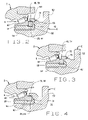
- FIG. 3 is a fragmentary sectional view showing a modified transfer ring
- FIG. 4 is a fragmentary sectional view showing a modified bearing cone through which torque is transferred from the CV joint to the hub;
- FIG. 5 is a fragmentary sectional view showing a modified CV joint and a modified coupler ring
- FIG. 6 is a fragmentary sectional view showing another modified CV joint without a stub shaft and a modified coupler ring.
- FIG. 7 is a fragmentary sectional view showing still another modified CV joint as well as a modified hub spindle.
- a corner module A for an automotive vehicle basically serves to support a corner of the vehicle on a road wheel B at that corner and to transfer drive torque to the road wheel B, so that the wheel B will propel the vehicle.
- the corner module A includes a suspension system component C, such as a steering knuckle or other suspension upright, and a wheel end D that couples the road wheel B to the suspension system component C to enable the wheel B rotate beyond the component C about an axis X while transferring both radial and thrust loads between the two.
- the corner module A includes a constant velocity (CV) joint E that transfers drive torque to the wheel end D which in turn transfers it to the road wheel B.
- CV constant velocity
- the wheel end D basically includes a housing 2 that is bolted to the suspension system component C, a hub 4 to which the road wheel B and CV joint E are attached, and an antifriction bearing 6 located between the housing 2 and the hub 4 to enable the latter to rotate with respect to the former about the axis X.
- the housing 2 has a generally cylindrical body 10 and a flange 12 that projects outwardly from the body 10 intermediate the ends of the body 10 .
- the inboard portion of the body 10 fits into the suspension system component C, while the flange 12 fits against the component C and receives bolts that secure the housing 2 to the component C.
- the hub 4 has a drive flange 14 that projects outwardly past the outboard end of the housing 2 and serves as a mount for the road wheel B and for a brake disk or drum as well. They are secured to the flange 14 with lug bolts 16 that project from the flange 14 .
- the hub 4 has a spindle 18 the projects axially into the housing 2 and a wheel pilot 20 that projects axially in the opposite direction to center the road wheel B on the hub 4 . Both the spindle 18 and pilot 20 are hollow. Indeed, the spindle 18 contains a through bore 22 that is generally uniform in diameter. It opens out of the outboard end of the hub within the pilot 20 .
- the spindle 18 where it merges with the flange 14 , has a shoulder 24 , while at its opposite end it is deformed outwardly in the provision of a formed end 26 that lies beyond the bearing 6 .
- the formed end 26 provides an abutment that is presented toward the shoulder 24 .
- U.S. Pat. Nos. 6,443,622 and 6,532,666 describe processes for upsetting the end of the spindle 18 to provide the formed end 26 and are incorporated herein by reference.
- the spindle 18 also has an external spline 28 that leads up to the formed end 26 .
- the bearing 6 enables the hub 4 to rotate relative to the housing 2 about the axis X. It includes outer raceways 30 that are presented inwardly toward the axis X and taper downwardly toward each other. They may be internal surfaces on the housing 2 itself.
- the bearing 6 also includes two inner races in the form of outboard and inboard cones 32 . Each cone 32 has a tapered raceway 34 that leads up to a thrust rib 36 at its large end, and the thrust rib 36 in turn leads out to a back face 38 that lies perpendicular to the axis X.
- the tapered raceway 34 of the outboard cone 32 is presented outwardly toward the outboard outer raceway 30 and is inclined in the same direction.
- the tapered raceway 34 of the inboard cone 32 is presented outwardly toward the inboard outer raceway 30 and is inclined in the same direction as that raceway 30 .
- the inboard cone 32 beyond the small end of its raceway 30 has an axially directed extension 40 that leads out to and abuts the corresponding end of the outboard cone 32 .
- the back face of the outboard cone 32 abuts the shoulder 24 where the hub flange 14 and spindle 18 merge.
- the back face 38 of the inboard cone 32 is presented toward, yet spaced from, the formed end 26 of the spindle 18 .
- a coupler ring 42 Captured between the back face 38 of the inboard cone 32 and the formed end 26 is a coupler ring 42 having an internal spline 44 that mates with the external spline 28 on the spindle 18 .
- the ring 42 also has an external spline 46 .
- the bearing 6 has rolling elements in the form of tapered rollers 48 arranged in outboard and inboard rows.
- the rollers 48 of outboard row lie between and contact the outboard raceways 30 and 32
- the rollers 48 of the inboard row lie between and contact the inboard raceways 30 and 32 .
- the geometry is such that the rollers 48 transfer radial loads between the housing 2 and hub spindle 18 and thrust loads in both axial directions as well.
- the rollers 48 of each row are on apex, meaning that the conical envelopes in which their tapered side faces lie and the conical envelopes in which the tapered raceways 30 and 32 that they contact lie have their apices at a common point along the axis X.
- the length of the axial extension 40 on the inboard cone 32 determines the setting for the bearing 6 , and preferably that setting is a slight preload, so that no internal clearances exist in the bearing 6 .
- the CV joint E transfers torque from an axle shaft (not shown) to the hub 4 of the wheel end A. It includes a bell 52 that lies beyond the inboard end of the wheel end A and a stub shaft 54 that projects from the bell 52 through the wheel end A.
- the bell 52 contains components that enable an axle shaft to transfer torque to the CV joint E while accommodating misalignment between the axle shaft and the axis X of the wheel end D.
- the bell 52 flares outwardly behind the formed end 26 at the inboard end of the spindle 18 to provide a shoulder 56 that abuts the end face of the formed end 26 on the hub spindle 18 .
- the bell 52 overlies the coupler ring 42 at the inboard end of the spindle 18 , and here it is provided with an internal spline 58 that mates with and engages the external spline 46 on the coupler ring 42 .
- torque that is applied to the CV joint E is transferred to the hub 4 of the wheel end D at the mating splines 46 and 58 and at the mating splines 44 and 28 .
- the stub shaft 54 projects from the bell 52 through the through bore 22 of the hub spindle 18 and out of the opposite end of the hub 4 , terminating within the wheel pilot 20 .
- it is provided with external threads 60 over which a nut 62 is threaded.
- the nut 62 is turned down against the outboard end face of the hub 18 , thus clamping the CV joint E and the hub 4 of the wheel end D together, with the shoulder 56 of the bell 52 bearing snugly against the formed end 26 on the hub spindle 18 .
- Other securing devices may be utilized to hold the hub 4 and CV joint E together.
- the diameter of the stub shaft and its spline represent limiting factors
- the diameter of the stub shaft 54 can be quite small, thus permitting use of a smaller tapered roller bearing 6 in the wheel end D.
- This derives from the removal of the torque transfer function from the stub shaft 54 and relocating it to the bell 52 of the CV joint E at a considerably greater diameter.
- the smaller tapered roller bearing 6 in comparison to more traditional bearings used in wheel ends, occupies less space, requires less bearing steel, and is lighter in weight. Yet it can accommodate the same or even greater radial and axial loads.
- the diameter of the stub shaft 54 can be reduced to that required to withstand the stresses caused by clamping the wheel end D to the CV joint E.
- This reduction in shaft diameter enables maximum radial downsizing of the inner and outer diameters on the hub spindle 18 as well as the size of the bearing 6 .
- the use of a tapered roller bearing enables the bearing size to be reduced substantially compared to other bearing types, such as ball bearing.
- the size reductions enable a considerable weight reduction of the corner module A which results in improved vehicle dynamics by lowering the unsprung mass of the vehicle.
- the torque may transfer through a transfer ring 64 that fits over the end of the bell 52 .
- the bell 52 at its end has an external spline 66 .
- the transfer ring 64 has an internal spline 68 that engages both the external spline 46 on the coupler ring 42 and the external spline 66 on the bell 52 .
- the transfer ring 64 is secured and thereby prevented from displacing axially by a weld 70 formed between its inboard end and the bell 52 .
- a modified transfer ring 72 ( FIG. 3 ) has an internal spline 74 that engages the external spline 46 on the coupler ring 42 , whereas the remainder of the internal surface on the ring 72 is cylindrical.
- the end of the bell 52 is likewise cylindrical, and here the ring 72 fits over the bell 52 .
- the ring 72 is attached firmly to the bell 52 through a weld 76 at the inboard end of the ring 72 .
- the CV joint E may transfer the torque applied to it to the bearing 6 which in turn transfers it to the hub spindle 18 .
- the bearing 6 is a modified inboard cone 80 ( FIG. 4 ) having an extended thrust rib 82 .
- the cone 80 also has an internal spline 84 that leads out to its back face 38 .
- the internal spline 84 engages the external spline 28 on the hub spindle 18 .
- the extended thrust rib 82 has an external spline 86 that engages the internal spline 58 in the bell 52 of the CV joint E, or the external spline 86 may be engaged by one of the transfer rings 64 or 72 fitted over the bell 52 .
- a slightly modified bell 90 ( FIG. 5 ) for the CV joint E has an external spline 92 .
- Drive torque transfers from the bell 90 to the hub spindle 18 through a modified transfer ring 94 that possesses an L-shaped configuration.
- the transfer ring 94 has a radial segment 96 that is clamped between the back face 38 of the inboard cone 32 and the formed end 26 and an axial segment 98 that projects from the radial segment 96 over the external spline 92 on the bell 90 .
- the radial segment 96 has an internal spline 100 that engages the external spline 28 on the hub spindle 18
- the axial segment 98 has an internal spline 102 that engages the external spline 92 on the bell 90 .
- the external spline 92 on the bell 90 of the CV joint E may have a slight helic angle so as to create an interference fit with the internal spline 102 on the axial segment 98 of the coupler ring 94 .
- the hub spindle 18 may be solid. That spindle 18 supports a slightly modified coupler ring 110 —one that is of somewhat extended length, but nevertheless has internal and external splines 112 and 114 , respectively.
- the internal spline 112 engages the external spline 28 on the hub spindle 18 .
- an annular groove 116 opens out of the coupler ring 110 midway between its ends.
- the coupler ring 110 has an elastomeric seal by 118 bonded to it at its inboard end, and it projects axially over the formed end 26 and at its end turns radially outwardly.
- the CV joint F includes a bell 120 provided with a reduced axially directed section 122 that forms the very end of the CV joint F.
- the CV joint F has no stub shaft.
- the end section 122 contains a cylindrical sealing surface 124 and an internal spline 126 to which the sealing surface 124 leads. It also has an annular groove 128 that opens inwardly out of the spline 126 .
- the end section 122 of the bell 120 fits over the coupler ring 110 that is around the hub spindle 18 , with the internal spline 126 on the end section 122 engaging the external spline 114 on the coupler ring 110 .
- the seal lip 118 bears against the internal sealing surface 124 on the end section 122 and establishes a generally static fluid barrier along the surface 124 .
- the end section 122 generally midway between the ends of its internal spline 112 has an annular groove 128 that opens inwardly.
- the two grooves 116 and 128 align and receive a cir-clip 130 that prevents the bell 120 from separating from the coupler ring 110 .
- the cir-clip 130 is split so that it can be expanded to pass over the external spline 114 on the coupler ring 110 while in the groove 130 of the end section 122 of the bell 120 .
- the groove 128 in the end section 122 is deep enough to accommodate the expansion.
- FIG. 7 Another CV joint G ( FIG. 7 ) couples to the hub 4 through the coupler ring 42 on the hub spindle 18 , but the hub spindle 18 is modified slightly in that it has an annular groove 140 that opens radially out of its formed end 26 .
- the CV joint G has a bell 142 and a reduced end section 144 that extends over the coupler ring 42 .
- the end section 144 contains an internal spline 146 that engages the external spline 46 on the coupler ring 42 .
- the end section 144 Within the spline 46 the end section 144 has an annular groove 148 that aligns with the groove 140 in the formed end 26 of the hub spindle 18 .
- the two grooves 140 and 148 receive a snap ring 150 that prevents the CV joint G from separating from the spindle 18 of the hub 4 .
- the snap ring 150 has a radial section 152 that spans the space between the formed end 26 of the spindle 18 and the end section 144 of the bell 142 , yet is received in the grooves 140 and 148 of both.
- the groove 148 in the end section 144 extends outwardly beyond the periphery of the radial section 152 a distance great enough to allow the radial section 152 to expand sufficiently to free itself of the groove 140 in the formed end 26 .
- the snap ring 150 is not continuous circumferentially, but is instead split so that it can expand against its natural bias and contract under that bias.
- the snap ring 150 also has an axial section 154 that projects axially away from the radial section 152 in the space between the end section 144 on the bell 142 and the formed end 26 on the hub spindle 18 .
- the snap ring 150 has a tail section 156 that turns radially inwardly from the end of the axial section 154 and is accessible at the inboard end of the through bore 22 that extends through the hub spindle 18 .
- the outer raceways 30 need not be surfaces in the housing 2 , but may instead be on separate outer races, called cups, fitted into the housing or on a single outer race called a double cup.
- the outboard cone 32 may be integrated into the spindle 18 , so that the outboard inner raceway 34 and the rib face at the large end of that raceway 34 are surfaces on the spindle 18 .
- the inboard cones 32 and 76 preferably should remain as a separate component to permit assembly of the bearing 6 and provide for adjustment of it.
Abstract
Description
Claims (6)
Priority Applications (1)
| Application Number | Priority Date | Filing Date | Title |
|---|---|---|---|
| US11/751,373 US7670059B2 (en) | 2007-04-16 | 2007-05-21 | Vehicle corner module |
Applications Claiming Priority (2)
| Application Number | Priority Date | Filing Date | Title |
|---|---|---|---|
| US91206007P | 2007-04-16 | 2007-04-16 | |
| US11/751,373 US7670059B2 (en) | 2007-04-16 | 2007-05-21 | Vehicle corner module |
Publications (2)
| Publication Number | Publication Date |
|---|---|
| US20080252030A1 US20080252030A1 (en) | 2008-10-16 |
| US7670059B2 true US7670059B2 (en) | 2010-03-02 |
Family
ID=39853019
Family Applications (1)
| Application Number | Title | Priority Date | Filing Date |
|---|---|---|---|
| US11/751,373 Active 2027-11-23 US7670059B2 (en) | 2007-04-16 | 2007-05-21 | Vehicle corner module |
Country Status (1)
| Country | Link |
|---|---|
| US (1) | US7670059B2 (en) |
Cited By (6)
| Publication number | Priority date | Publication date | Assignee | Title |
|---|---|---|---|---|
| US20080273824A1 (en) * | 2007-02-01 | 2008-11-06 | Jtekt Corporation | Bearing device for axle and fixing structure using the same |
| US20090252551A1 (en) * | 2008-03-28 | 2009-10-08 | Jtekt Corporation | Wheel bearing assembly, and manufacturing method thereof |
| US20100285890A1 (en) * | 2008-01-10 | 2010-11-11 | The Timken Company | Compact wheel end and corner module |
| US20110182541A1 (en) * | 2009-11-24 | 2011-07-28 | Schaeffler Technologies Gmbh & Co. Kg | Radlagereinheit mit funktionskombiniertem waelznietbund |
| US10300740B2 (en) | 2014-07-30 | 2019-05-28 | Honeywell International Inc. | Wheel hub bearing bore |
| US20230160427A1 (en) * | 2021-11-23 | 2023-05-25 | Schaeffler Technologies AG & Co. KG | Clamping configuration for wheel bearing assembly |
Families Citing this family (1)
| Publication number | Priority date | Publication date | Assignee | Title |
|---|---|---|---|---|
| US8353390B2 (en) * | 2010-03-10 | 2013-01-15 | GM Global Technology Operations LLC | Splash shield for brake corner assembly |
Citations (12)
| Publication number | Priority date | Publication date | Assignee | Title |
|---|---|---|---|---|
| GB2191267A (en) | 1986-05-30 | 1987-12-09 | Loehr & Bromkamp Gmbh | Hub assembly |
| US4893960A (en) | 1986-10-24 | 1990-01-16 | Lohr & Bromkamp Gmbh | Wheel Bearing/constant velocity joint unit |
| US5806936A (en) | 1995-09-18 | 1998-09-15 | Gkn Glaenzer Spicer | Drive-wheel hub for a motor vehicle |
| US6299360B1 (en) | 1999-08-25 | 2001-10-09 | The Timken Company | Hub assembly having a captured ring and process for assembling the same |
| US20020044706A1 (en) * | 2000-07-31 | 2002-04-18 | Shigeoki Kayama | Drive unit for wheel and assembly method for the same |
| US6601994B2 (en) | 2001-12-05 | 2003-08-05 | The Timken Company | Compact hub assembly |
| US6616340B2 (en) | 2001-11-28 | 2003-09-09 | The Timken Company | Hub assembly with driven hub |
| US6648518B2 (en) * | 2001-02-08 | 2003-11-18 | Gkn Automotive, Inc. | Constant velocity joint assembly with retention member |
| US6659650B2 (en) * | 2002-01-28 | 2003-12-09 | The Timken Company | Wheel bearing with improved cage |
| US6739978B2 (en) | 2001-09-28 | 2004-05-25 | The Timken Company | Wheel hub/joint unit with clamping and separating device |
| US6749517B2 (en) | 2000-08-22 | 2004-06-15 | Nsk Ltd. | Wheel drive unit |
| US6886987B2 (en) * | 2002-05-23 | 2005-05-03 | Skf Indunstrie S.P.A. | Hub-bearing assembly for a driving wheel of a vehicle, particularly a truck |
-
2007
- 2007-05-21 US US11/751,373 patent/US7670059B2/en active Active
Patent Citations (12)
| Publication number | Priority date | Publication date | Assignee | Title |
|---|---|---|---|---|
| GB2191267A (en) | 1986-05-30 | 1987-12-09 | Loehr & Bromkamp Gmbh | Hub assembly |
| US4893960A (en) | 1986-10-24 | 1990-01-16 | Lohr & Bromkamp Gmbh | Wheel Bearing/constant velocity joint unit |
| US5806936A (en) | 1995-09-18 | 1998-09-15 | Gkn Glaenzer Spicer | Drive-wheel hub for a motor vehicle |
| US6299360B1 (en) | 1999-08-25 | 2001-10-09 | The Timken Company | Hub assembly having a captured ring and process for assembling the same |
| US20020044706A1 (en) * | 2000-07-31 | 2002-04-18 | Shigeoki Kayama | Drive unit for wheel and assembly method for the same |
| US6749517B2 (en) | 2000-08-22 | 2004-06-15 | Nsk Ltd. | Wheel drive unit |
| US6648518B2 (en) * | 2001-02-08 | 2003-11-18 | Gkn Automotive, Inc. | Constant velocity joint assembly with retention member |
| US6739978B2 (en) | 2001-09-28 | 2004-05-25 | The Timken Company | Wheel hub/joint unit with clamping and separating device |
| US6616340B2 (en) | 2001-11-28 | 2003-09-09 | The Timken Company | Hub assembly with driven hub |
| US6601994B2 (en) | 2001-12-05 | 2003-08-05 | The Timken Company | Compact hub assembly |
| US6659650B2 (en) * | 2002-01-28 | 2003-12-09 | The Timken Company | Wheel bearing with improved cage |
| US6886987B2 (en) * | 2002-05-23 | 2005-05-03 | Skf Indunstrie S.P.A. | Hub-bearing assembly for a driving wheel of a vehicle, particularly a truck |
Cited By (10)
| Publication number | Priority date | Publication date | Assignee | Title |
|---|---|---|---|---|
| US20080273824A1 (en) * | 2007-02-01 | 2008-11-06 | Jtekt Corporation | Bearing device for axle and fixing structure using the same |
| US20100285890A1 (en) * | 2008-01-10 | 2010-11-11 | The Timken Company | Compact wheel end and corner module |
| US8465211B2 (en) | 2008-01-10 | 2013-06-18 | The Timken Company | Compact wheel end and corner module |
| US20090252551A1 (en) * | 2008-03-28 | 2009-10-08 | Jtekt Corporation | Wheel bearing assembly, and manufacturing method thereof |
| US8052332B2 (en) * | 2008-03-28 | 2011-11-08 | Jtekt Corporation | Wheel bearing assembly, and manufacturing method thereof |
| US20110182541A1 (en) * | 2009-11-24 | 2011-07-28 | Schaeffler Technologies Gmbh & Co. Kg | Radlagereinheit mit funktionskombiniertem waelznietbund |
| US8714830B2 (en) * | 2009-11-24 | 2014-05-06 | Schaeffler Technologies AG & Co. KG | Radlagereinheit mit funktionskombiniertem waelznietbund |
| US10300740B2 (en) | 2014-07-30 | 2019-05-28 | Honeywell International Inc. | Wheel hub bearing bore |
| US20230160427A1 (en) * | 2021-11-23 | 2023-05-25 | Schaeffler Technologies AG & Co. KG | Clamping configuration for wheel bearing assembly |
| US11879500B2 (en) * | 2021-11-23 | 2024-01-23 | Schaeffler Technologies AG & Co. KG | Clamping configuration for wheel bearing assembly |
Also Published As
| Publication number | Publication date |
|---|---|
| US20080252030A1 (en) | 2008-10-16 |
Similar Documents
| Publication | Publication Date | Title |
|---|---|---|
| US7670059B2 (en) | Vehicle corner module | |
| JP4557223B2 (en) | Drive wheel bearing device | |
| CN100554005C (en) | Wheel hub and connector unit | |
| US8465211B2 (en) | Compact wheel end and corner module | |
| EP2602123B1 (en) | An integrated hub-bearing assembly for the wheel of a motor vehicle | |
| WO2009023506A1 (en) | Solid rear axle for an automotive vehicle | |
| US20070098315A1 (en) | Bearing apparatus for a wheel of vehicle | |
| EP1125765A2 (en) | Apparatus for driving wheel of automobile | |
| US8186888B2 (en) | Wheel bearing and a bearing apparatus for a wheel of vehicle of semi-floating type having the wheel bearing | |
| US7699405B2 (en) | Vehicle wheel end assemblies and methods of assembly thereof | |
| US6102489A (en) | Wheel support arrangement for a vehicle drive axle | |
| US9493035B2 (en) | Flanged hub-bearing unit | |
| US8753018B2 (en) | Wheel end support bearing | |
| EP2957432B1 (en) | Hub-bearing having a light alloy rotor-hub | |
| US8714828B2 (en) | Wheel hub assembly with dual rows of rolling elements | |
| JP2010159011A (en) | Hub unit for supporting drive wheel | |
| US20130257005A1 (en) | Compact wheel end with coupler | |
| JP4150317B2 (en) | Wheel bearing device | |
| US20230063439A1 (en) | Motor vehicle wheel assembly | |
| JP2007162828A (en) | Wheel bearing device and axle module equipped therewith | |
| WO2008134415A1 (en) | Wheel end with double row bearing having dissimilar contact angles | |
| CN100469600C (en) | Wheel bearing and semi-floating type wheel bearing device having the same | |
| US20220324255A1 (en) | Wheel hub assembly with optimized raceways | |
| KR20200120564A (en) | Wheel bearing assembly | |
| JP2023108962A (en) | hub unit bearing |
Legal Events
| Date | Code | Title | Description |
|---|---|---|---|
| AS | Assignment |
Owner name: THE TIMKEN COMPANY, OHIO Free format text: ASSIGNMENT OF ASSIGNORS INTEREST;ASSIGNORS:GRADU, MIRCEA;DOUGHERTY, JOHN D.;HENSON, CHRISTOPHER W.;REEL/FRAME:019322/0164;SIGNING DATES FROM 20070503 TO 20070508 Owner name: THE TIMKEN COMPANY,OHIO Free format text: ASSIGNMENT OF ASSIGNORS INTEREST;ASSIGNORS:GRADU, MIRCEA;DOUGHERTY, JOHN D.;HENSON, CHRISTOPHER W.;SIGNING DATES FROM 20070503 TO 20070508;REEL/FRAME:019322/0164 |
|
| FEPP | Fee payment procedure |
Free format text: PAYOR NUMBER ASSIGNED (ORIGINAL EVENT CODE: ASPN); ENTITY STATUS OF PATENT OWNER: LARGE ENTITY |
|
| STCF | Information on status: patent grant |
Free format text: PATENTED CASE |
|
| FPAY | Fee payment |
Year of fee payment: 4 |
|
| FEPP | Fee payment procedure |
Free format text: PAYOR NUMBER ASSIGNED (ORIGINAL EVENT CODE: ASPN); ENTITY STATUS OF PATENT OWNER: LARGE ENTITY Free format text: PAYER NUMBER DE-ASSIGNED (ORIGINAL EVENT CODE: RMPN); ENTITY STATUS OF PATENT OWNER: LARGE ENTITY |
|
| MAFP | Maintenance fee payment |
Free format text: PAYMENT OF MAINTENANCE FEE, 8TH YEAR, LARGE ENTITY (ORIGINAL EVENT CODE: M1552) Year of fee payment: 8 |
|
| MAFP | Maintenance fee payment |
Free format text: PAYMENT OF MAINTENANCE FEE, 12TH YEAR, LARGE ENTITY (ORIGINAL EVENT CODE: M1553); ENTITY STATUS OF PATENT OWNER: LARGE ENTITY Year of fee payment: 12 |