EP1302389B1 - Heckteilaufbau eines Kraftfahrzeuges - Google Patents
Heckteilaufbau eines Kraftfahrzeuges Download PDFInfo
- Publication number
- EP1302389B1 EP1302389B1 EP02256451A EP02256451A EP1302389B1 EP 1302389 B1 EP1302389 B1 EP 1302389B1 EP 02256451 A EP02256451 A EP 02256451A EP 02256451 A EP02256451 A EP 02256451A EP 1302389 B1 EP1302389 B1 EP 1302389B1
- Authority
- EP
- European Patent Office
- Prior art keywords
- wall
- side member
- transversely
- rear side
- body structure
- Prior art date
- Legal status (The legal status is an assumption and is not a legal conclusion. Google has not performed a legal analysis and makes no representation as to the accuracy of the status listed.)
- Expired - Lifetime
Links
Images


Classifications
-
- B—PERFORMING OPERATIONS; TRANSPORTING
- B62—LAND VEHICLES FOR TRAVELLING OTHERWISE THAN ON RAILS
- B62D—MOTOR VEHICLES; TRAILERS
- B62D25/00—Superstructure or monocoque structure sub-units; Parts or details thereof not otherwise provided for
- B62D25/20—Floors or bottom sub-units
- B62D25/2009—Floors or bottom sub-units in connection with other superstructure subunits
- B62D25/2027—Floors or bottom sub-units in connection with other superstructure subunits the subunits being rear structures
Definitions
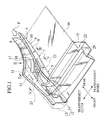
- a rear cross-member 19 extended in the vehicle transverse direction is connected to a front part of the protruded portion 15 of the side sill inner 4.
- This rear cross-member 19 has a section bent in a crank shape.
- the rear floor 16 and a cover portion 20 formed downward from its front end are connected to the rear cross-member 19 to form a closed section 21 along the vehicle transverse direction, thereby increasing vehicle body rigidity.
Landscapes
- Engineering & Computer Science (AREA)
- Chemical & Material Sciences (AREA)
- Combustion & Propulsion (AREA)
- Transportation (AREA)
- Mechanical Engineering (AREA)
- Body Structure For Vehicles (AREA)
Claims (6)
- Hintere Fahrzeugkarosseriestruktur, die Folgendes umfasst:einen hinteren Längsträger (4), der Folgendes einschließt:einen vorderen Abschnitt (5) vor einem hinteren Radkasten (1), der sich in einer Fahrzeuglängsrichtung erstreckt,einen mittleren Abschnitt (7), der sich hinter dem vorderen Abschnitt (5) um den hinteren Radkasten (1) erstreckt, undeinen hinteren Abschnitt (6), der sich hinter dem mittleren Abschnitt (7) erstreckt und eine sich in Längsrichtung erstreckende erste Wand (10) auf seiner in Querrichtung äußeren Seite hat,ein sich in Längsrichtung erstreckendes Seitenschwellerinneres (14), wobei ein hinterer Abschnitt desselben außerhalb des vorderen Abschnitts (5) des hinteren Längsträgers (4) in Querrichtung verbunden ist, undeinen hinteren Boden (16), der mit dem hinteren Längsträger (4) und dem Seitenschwellerinneren (14) verbunden ist,wobei das Seitenschwellerinnere (14) eine sich in Längsrichtung erstreckende zweite Wand (17) hat, die innerhalb der Breite des hinteren Längsträgers (4) aufgenommen wird, um einen unteren Abschnitt (8) des hinteren Längsträgers (4) mit dem hinteren Boden (16) zu verbinden, und
wobei die zweite Wand (17) mit der ersten Wand (10) verbunden ist, so dass die erste und die zweite Wand (10, 17) eine krummlinige Fläche darstellen, die sich in der Fahrzeuglängsrichtung erstreckt. - Hintere Fahrzeugkarosseriestruktur nach Anspruch 1,
wobei ein unterer Abschnitt (8) des hinteren Längsträgers (4) sich durchgehend über den vorderen Abschnitt (5), den mittleren Abschnitt (7) und den hinteren Abschnitt (6) erstreckt und eine dritte Wand (9) längs einer in Querrichtung inneren Seite desselben hat, im Wesentlichen parallel mit der krummlinigen Fläche der ersten und der zweiten Wand (10, 17), und
wobei die krummlinige Fläche der ersten und der zweiten Wand (10, 17), die dritte Wand (9), der untere Abschnitt (8) des hinteren Längsträgers (4) und der hintere Boden (16) zusammenwirken, um eine geschlossene Sektionsstruktur zu bilden, die sich in der Fahrzeuglängsrichtung erstreckt. - Hintere Fahrzeugkarosseriestruktur nach Anspruch 1,
wobei der mittlere Abschnitt (7) des hinteren Längsträgers (4) eine weitere Wand (11) hat, die durchgehend von einem vorderen Ende der ersten Wand (10) des hinteren Abschnitts (6) bis zu einem in Querrichtung äußeren hinteren Ende des vorderen Abschnitts (5) bereitgestellt wird, und
wobei die zweite Wand (17) des Seitenschwellerinneren (14) an ihrem hinteren Ende einen Flanschabschnitt (18) hat, der in der Nachbarschaft eines Übergangspunktes von der ersten Wand (10) zu der weiteren Wand (11) am hinteren Längsträger (4) befestigt ist, im Wesentlichen auf der gleichen Ebene wie die zweite Wand (17). - Hintere Fahrzeugkarosseriestruktur nach Anspruch 3, wobei das Seitenschwellerinnere (14) einen vorspringenden Abschnitt (15) einschließt, der von einer Hauptfläche desselben allmählich in Querrichtung nach innen vorspringt, während sie sich rückwärts annähert, aufgenommen innerhalb der Breite des hinteren Längsträgers (4), und eine in Querrichtung innere Seite des vorspringenden Abschnitts (15) die zweite Wand (17) darstellt.
- Hintere Fahrzeugkarosseriestruktur nach Anspruch 4, das ferner Folgendes umfasst:eine erste Verstärkung (22), die auf der in Querrichtung inneren Seite der zweiten Wand (17) des Seitenschwellerinneren (14) angeordnet und am unteren Abschnitt (8) des hinteren Längsträgers (4) befestigt ist, undeine zweite Verstärkung (23), die auf der in Querrichtung äußeren Seite der zweiten Wand (17) des Seitenschwellerinneren (14) angeordnet und an einem unteren Abschnitt des vorspringenden Abschnitts (15) befestigt ist,wobei die erste und die zweite Verstärkung (22, 23) auf gegenüberliegenden Seiten derselben Flansche (22a, 23a) haben, die an der zwischen denselben angeordneten zweiten Wand (17) zu befestigen sind.
- Hintere Fahrzeugkarosseriestruktur nach Anspruch 5, wobei:die erste Verstärkung (22) auf ihrer in Querrichtung inneren Seite den anderen Flansch (22b) hat, der an einer vierten Wand (9) des hinteren Längsträgers (4) zu befestigen ist, die sich in Längsrichtung längs einer in Querrichtung inneren Seite desselben erstreckt, unddie zweite Verstärkung (23) auf ihrer in Querrichtung äußeren Seite den anderen Flansch (23b) hat, der an der Hauptfläche des Seitenschwellerinneren (14) zu befestigen ist.
Applications Claiming Priority (2)
| Application Number | Priority Date | Filing Date | Title |
|---|---|---|---|
| JP2001317013 | 2001-10-15 | ||
| JP2001317013A JP3674571B2 (ja) | 2001-10-15 | 2001-10-15 | 車体後部構造 |
Publications (2)
| Publication Number | Publication Date |
|---|---|
| EP1302389A1 EP1302389A1 (de) | 2003-04-16 |
| EP1302389B1 true EP1302389B1 (de) | 2007-08-08 |
Family
ID=19134945
Family Applications (1)
| Application Number | Title | Priority Date | Filing Date |
|---|---|---|---|
| EP02256451A Expired - Lifetime EP1302389B1 (de) | 2001-10-15 | 2002-09-17 | Heckteilaufbau eines Kraftfahrzeuges |
Country Status (5)
| Country | Link |
|---|---|
| US (1) | US6672653B2 (de) |
| EP (1) | EP1302389B1 (de) |
| JP (1) | JP3674571B2 (de) |
| CN (2) | CN100465044C (de) |
| DE (1) | DE60221616T2 (de) |
Families Citing this family (27)
| Publication number | Priority date | Publication date | Assignee | Title |
|---|---|---|---|---|
| DE10060784B4 (de) * | 2000-12-07 | 2006-03-16 | Ise Innomotive Systems Europe Gmbh | Heckmodul für Personenkraftfahrzeuge |
| JP4168812B2 (ja) * | 2003-04-07 | 2008-10-22 | 三菱自動車工業株式会社 | 自動車の車体後部の結合構造 |
| JP4352769B2 (ja) * | 2003-06-11 | 2009-10-28 | マツダ株式会社 | 自動車の下部車体構造 |
| JP4421380B2 (ja) * | 2004-06-01 | 2010-02-24 | 本田技研工業株式会社 | 車体フレーム構造 |
| JP4413731B2 (ja) * | 2004-09-28 | 2010-02-10 | 本田技研工業株式会社 | サイドシルガーニッシュ |
| US7322640B2 (en) * | 2004-10-08 | 2008-01-29 | General Motors Corporation | Hydroformed and roll-formed cross sill assembly for vehicles and method of making same |
| JP4404036B2 (ja) * | 2005-09-21 | 2010-01-27 | トヨタ自動車株式会社 | 車両後部構造 |
| JP4815979B2 (ja) * | 2005-10-05 | 2011-11-16 | マツダ株式会社 | 自動車の下部車体構造 |
| JP4654917B2 (ja) * | 2006-01-12 | 2011-03-23 | 日産自動車株式会社 | 車体後部構造 |
| JP4838604B2 (ja) * | 2006-03-15 | 2011-12-14 | ダイハツ工業株式会社 | 車両のリヤサイドメンバー構造 |
| DE102007018167A1 (de) * | 2007-04-18 | 2008-10-23 | Dr. Ing. H.C. F. Porsche Aktiengesellschaft | Heckseitige Fahrzeugkarosseriestruktur |
| US7527327B2 (en) * | 2007-09-18 | 2009-05-05 | Ford Global Technologies, Llc | Rear vehicle subassembly having a towing hitch member |
| CN101835676A (zh) * | 2007-10-24 | 2010-09-15 | 丰田自动车株式会社 | 车体侧部构造 |
| US7997618B2 (en) * | 2008-11-27 | 2011-08-16 | GM Global Technology Operations LLC | Rear frame for a motor vehicle |
| CN101665124B (zh) * | 2009-09-24 | 2011-03-23 | 重庆长安汽车股份有限公司 | 汽车后地板边板 |
| US8696051B2 (en) * | 2010-12-22 | 2014-04-15 | Tesla Motors, Inc. | System for absorbing and distributing side impact energy utilizing a side sill assembly with a collapsible sill insert |
| US20120161472A1 (en) | 2010-12-22 | 2012-06-28 | Tesla Motors, Inc. | System for Absorbing and Distributing Side Impact Energy Utilizing an Integrated Battery Pack |
| JP5337184B2 (ja) * | 2011-03-04 | 2013-11-06 | 本田技研工業株式会社 | 自動車の車体後部構造 |
| WO2013018417A1 (ja) * | 2011-08-02 | 2013-02-07 | 本田技研工業株式会社 | 車体後部構造 |
| KR101326516B1 (ko) * | 2012-03-02 | 2013-11-08 | 기아자동차주식회사 | 차량용 리어사이드 멤버와 사이드 실 결합 장치 |
| KR101703586B1 (ko) * | 2015-02-09 | 2017-02-07 | 현대자동차 주식회사 | 차체의 지지 구조 |
| KR101724897B1 (ko) * | 2015-09-10 | 2017-04-07 | 현대자동차주식회사 | 리어 사이드 멤버 |
| FR3063709B1 (fr) * | 2017-03-07 | 2019-06-07 | Renault S.A.S | Structure de caisse de vehicule automobile. |
| JP7074039B2 (ja) | 2018-12-06 | 2022-05-24 | トヨタ自動車株式会社 | 車体構造 |
| RU190334U1 (ru) * | 2019-02-08 | 2019-06-26 | Публичное акционерное общество "АВТОВАЗ" | Конструкция задней части кузова автомобиля |
| CN121406886A (zh) | 2020-01-03 | 2026-01-27 | 特斯拉公司 | 从粘土矿物中选择性提取锂 |
| JP2023150062A (ja) * | 2022-03-31 | 2023-10-16 | 本田技研工業株式会社 | 車体の後部構造 |
Family Cites Families (14)
| Publication number | Priority date | Publication date | Assignee | Title |
|---|---|---|---|---|
| US3528699A (en) * | 1968-12-11 | 1970-09-15 | Budd Co | Vehicle body side sill to rear sill transition structure |
| JPS5863168U (ja) * | 1981-10-23 | 1983-04-27 | マツダ株式会社 | 自動車の車体構造 |
| JPS58128970A (ja) * | 1982-01-27 | 1983-08-01 | Mazda Motor Corp | 自動車の車体構造 |
| JPS58133967A (ja) * | 1982-02-04 | 1983-08-09 | Mazda Motor Corp | 自動車の後部車体構造 |
| US4669776A (en) * | 1985-03-19 | 1987-06-02 | Mazda Motor Corporation | Front body construction for motor vehicle |
| DE4020363C2 (de) * | 1990-06-27 | 2000-11-30 | Opel Adam Ag | Längsträger für Personenkraftwagen |
| JP2978546B2 (ja) * | 1990-09-20 | 1999-11-15 | マツダ株式会社 | 自動車の後部車体構造 |
| JP3179187B2 (ja) * | 1992-06-09 | 2001-06-25 | マツダ株式会社 | 自動車の車体構造 |
| JP3206424B2 (ja) * | 1996-03-25 | 2001-09-10 | トヨタ自動車株式会社 | 自動車の車体構造 |
| JPH10297541A (ja) * | 1997-04-23 | 1998-11-10 | Toyota Motor Corp | 車両のリヤアンダボデー構造 |
| DE19811781B4 (de) * | 1998-03-18 | 2004-01-29 | Daimlerchrysler Ag | Karosseriestruktur |
| JP3518397B2 (ja) | 1999-03-09 | 2004-04-12 | 日産自動車株式会社 | 車体構造 |
| JP2001247056A (ja) * | 2000-03-08 | 2001-09-11 | Nissan Motor Co Ltd | 車体後部構造 |
| JP2001317013A (ja) | 2000-05-10 | 2001-11-16 | Shimizu Corp | セグメント架設用移動足場 |
-
2001
- 2001-10-15 JP JP2001317013A patent/JP3674571B2/ja not_active Expired - Lifetime
-
2002
- 2002-09-17 EP EP02256451A patent/EP1302389B1/de not_active Expired - Lifetime
- 2002-09-17 DE DE60221616T patent/DE60221616T2/de not_active Expired - Lifetime
- 2002-10-11 CN CNB021468133A patent/CN100465044C/zh not_active Expired - Lifetime
- 2002-10-11 US US10/268,679 patent/US6672653B2/en not_active Expired - Lifetime
- 2002-10-11 CN CN02252369U patent/CN2590828Y/zh not_active Expired - Fee Related
Also Published As
| Publication number | Publication date |
|---|---|
| JP3674571B2 (ja) | 2005-07-20 |
| JP2003118644A (ja) | 2003-04-23 |
| DE60221616D1 (de) | 2007-09-20 |
| DE60221616T2 (de) | 2008-05-21 |
| US20030071490A1 (en) | 2003-04-17 |
| CN2590828Y (zh) | 2003-12-10 |
| CN100465044C (zh) | 2009-03-04 |
| CN1412062A (zh) | 2003-04-23 |
| US6672653B2 (en) | 2004-01-06 |
| EP1302389A1 (de) | 2003-04-16 |
Similar Documents
| Publication | Publication Date | Title |
|---|---|---|
| US6672653B2 (en) | Rear vehicle body structure | |
| EP1808362B1 (de) | Fahrzeugaufbau | |
| EP1555191B1 (de) | Aufprallenergieabsorbierende Struktur eines Fahrzeugrahmens | |
| US8075047B2 (en) | Automotive vehicle body structure | |
| US7641270B2 (en) | Car body frame member | |
| CN100460264C (zh) | 汽车侧梁及具有该侧梁的汽车 | |
| CN112109811B (zh) | 车身结构和包括该车身结构的车辆 | |
| JPH0820363A (ja) | 車体のサイドシル構造 | |
| CN102050151A (zh) | 车辆的前部车身结构 | |
| JP2006199132A (ja) | 車体下側部構造 | |
| JP3876279B2 (ja) | 自動車のピラー補強構造 | |
| US20200180703A1 (en) | Vehicle Body Structure | |
| JP2006297966A (ja) | 車体のフロア構造 | |
| JP2019137352A (ja) | 車体構造 | |
| JP2000095151A (ja) | 車両のロッカ部構造 | |
| JPH08119152A (ja) | 自動車の車体構造 | |
| EP1177968B1 (de) | Stossenergieabsorbierende Struktur für ein Kraftfahrzeug | |
| JP2004155393A (ja) | 車体前部構造 | |
| JPH08133131A (ja) | 車両用フロアのクロスメンバ構造 | |
| JPH09207824A (ja) | 車両の下部車体構造 | |
| JPH07232555A (ja) | ドアインパクトビーム取付構造 | |
| JPH11192977A (ja) | 自動車の車体フレーム補強構造 | |
| US7165805B2 (en) | Vehicle front body structure | |
| JP4304449B2 (ja) | 車両の前部車体構造 | |
| JP2001055163A (ja) | 車体構造 |
Legal Events
| Date | Code | Title | Description |
|---|---|---|---|
| PUAI | Public reference made under article 153(3) epc to a published international application that has entered the european phase |
Free format text: ORIGINAL CODE: 0009012 |
|
| 17P | Request for examination filed |
Effective date: 20021003 |
|
| AK | Designated contracting states |
Designated state(s): AT BE BG CH CY CZ DE DK EE ES FI FR GB GR IE IT LI LU MC NL PT SE SK TR |
|
| AX | Request for extension of the european patent |
Extension state: AL LT LV MK RO SI |
|
| RAP1 | Party data changed (applicant data changed or rights of an application transferred) |
Owner name: RENAULT S.A.S. Owner name: NISSAN MOTOR COMPANY, LIMITED |
|
| AKX | Designation fees paid |
Designated state(s): DE FR GB |
|
| GRAP | Despatch of communication of intention to grant a patent |
Free format text: ORIGINAL CODE: EPIDOSNIGR1 |
|
| GRAS | Grant fee paid |
Free format text: ORIGINAL CODE: EPIDOSNIGR3 |
|
| GRAA | (expected) grant |
Free format text: ORIGINAL CODE: 0009210 |
|
| AK | Designated contracting states |
Kind code of ref document: B1 Designated state(s): DE FR GB |
|
| REG | Reference to a national code |
Ref country code: GB Ref legal event code: FG4D |
|
| REF | Corresponds to: |
Ref document number: 60221616 Country of ref document: DE Date of ref document: 20070920 Kind code of ref document: P |
|
| ET | Fr: translation filed | ||
| PLBE | No opposition filed within time limit |
Free format text: ORIGINAL CODE: 0009261 |
|
| STAA | Information on the status of an ep patent application or granted ep patent |
Free format text: STATUS: NO OPPOSITION FILED WITHIN TIME LIMIT |
|
| 26N | No opposition filed |
Effective date: 20080509 |
|
| REG | Reference to a national code |
Ref country code: FR Ref legal event code: PLFP Year of fee payment: 15 |
|
| REG | Reference to a national code |
Ref country code: FR Ref legal event code: PLFP Year of fee payment: 16 |
|
| REG | Reference to a national code |
Ref country code: FR Ref legal event code: PLFP Year of fee payment: 17 |
|
| PGFP | Annual fee paid to national office [announced via postgrant information from national office to epo] |
Ref country code: FR Payment date: 20210812 Year of fee payment: 20 |
|
| PGFP | Annual fee paid to national office [announced via postgrant information from national office to epo] |
Ref country code: DE Payment date: 20210810 Year of fee payment: 20 Ref country code: GB Payment date: 20210811 Year of fee payment: 20 |
|
| REG | Reference to a national code |
Ref country code: DE Ref legal event code: R071 Ref document number: 60221616 Country of ref document: DE |
|
| REG | Reference to a national code |
Ref country code: GB Ref legal event code: PE20 Expiry date: 20220916 |
|
| PG25 | Lapsed in a contracting state [announced via postgrant information from national office to epo] |
Ref country code: GB Free format text: LAPSE BECAUSE OF EXPIRATION OF PROTECTION Effective date: 20220916 |