EP1285808A1 - Verfahren und Vorrichtung zur Fahrzeugsteuerung bzw.-regelung - Google Patents
Verfahren und Vorrichtung zur Fahrzeugsteuerung bzw.-regelung Download PDFInfo
- Publication number
- EP1285808A1 EP1285808A1 EP02020597A EP02020597A EP1285808A1 EP 1285808 A1 EP1285808 A1 EP 1285808A1 EP 02020597 A EP02020597 A EP 02020597A EP 02020597 A EP02020597 A EP 02020597A EP 1285808 A1 EP1285808 A1 EP 1285808A1
- Authority
- EP
- European Patent Office
- Prior art keywords
- vehicle
- speed
- acceleration
- distance
- signal
- Prior art date
- Legal status (The legal status is an assumption and is not a legal conclusion. Google has not performed a legal analysis and makes no representation as to the accuracy of the status listed.)
- Ceased
Links
- 238000000034 method Methods 0.000 title claims abstract description 163
- 230000001105 regulatory effect Effects 0.000 title claims abstract description 16
- 230000001276 controlling effect Effects 0.000 title claims abstract description 11
- 230000001133 acceleration Effects 0.000 claims abstract description 227
- 230000006870 function Effects 0.000 claims description 88
- 230000033228 biological regulation Effects 0.000 claims description 24
- 230000001419 dependent effect Effects 0.000 claims description 24
- 230000015654 memory Effects 0.000 claims description 24
- 230000007704 transition Effects 0.000 claims description 22
- 230000008569 process Effects 0.000 claims description 19
- 238000001914 filtration Methods 0.000 claims description 15
- 230000008859 change Effects 0.000 claims description 13
- 230000009467 reduction Effects 0.000 claims description 12
- 230000000694 effects Effects 0.000 claims description 11
- 238000012937 correction Methods 0.000 claims description 9
- 238000001514 detection method Methods 0.000 claims description 8
- 230000007423 decrease Effects 0.000 claims description 7
- 230000010354 integration Effects 0.000 claims description 6
- 230000003321 amplification Effects 0.000 claims description 5
- 238000012544 monitoring process Methods 0.000 claims description 5
- 238000003199 nucleic acid amplification method Methods 0.000 claims description 5
- 238000005259 measurement Methods 0.000 claims description 4
- 230000002123 temporal effect Effects 0.000 claims description 4
- 238000009499 grossing Methods 0.000 claims description 3
- 238000004088 simulation Methods 0.000 claims description 3
- 230000000295 complement effect Effects 0.000 claims description 2
- 238000013016 damping Methods 0.000 claims description 2
- 230000036962 time dependent Effects 0.000 claims description 2
- 230000007257 malfunction Effects 0.000 claims 2
- 230000003287 optical effect Effects 0.000 claims 1
- 238000004904 shortening Methods 0.000 claims 1
- 238000012546 transfer Methods 0.000 claims 1
- 230000002829 reductive effect Effects 0.000 description 11
- 230000006399 behavior Effects 0.000 description 9
- 238000004364 calculation method Methods 0.000 description 8
- 230000008901 benefit Effects 0.000 description 7
- 238000010586 diagram Methods 0.000 description 6
- 239000012530 fluid Substances 0.000 description 6
- 238000012545 processing Methods 0.000 description 5
- 238000001228 spectrum Methods 0.000 description 5
- 230000005540 biological transmission Effects 0.000 description 4
- 238000006243 chemical reaction Methods 0.000 description 4
- 230000003247 decreasing effect Effects 0.000 description 4
- 238000011161 development Methods 0.000 description 4
- 238000011156 evaluation Methods 0.000 description 4
- 230000004044 response Effects 0.000 description 4
- 238000003825 pressing Methods 0.000 description 3
- 239000000243 solution Substances 0.000 description 3
- 238000002604 ultrasonography Methods 0.000 description 3
- 239000002131 composite material Substances 0.000 description 2
- 230000006872 improvement Effects 0.000 description 2
- 238000011835 investigation Methods 0.000 description 2
- 238000007639 printing Methods 0.000 description 2
- 230000035484 reaction time Effects 0.000 description 2
- 230000002787 reinforcement Effects 0.000 description 2
- 238000005070 sampling Methods 0.000 description 2
- 230000002269 spontaneous effect Effects 0.000 description 2
- 230000009471 action Effects 0.000 description 1
- 230000003213 activating effect Effects 0.000 description 1
- 230000006978 adaptation Effects 0.000 description 1
- 238000013459 approach Methods 0.000 description 1
- 238000004422 calculation algorithm Methods 0.000 description 1
- 238000010276 construction Methods 0.000 description 1
- 230000036461 convulsion Effects 0.000 description 1
- 230000008878 coupling Effects 0.000 description 1
- 230000001934 delay Effects 0.000 description 1
- 238000009795 derivation Methods 0.000 description 1
- 238000009826 distribution Methods 0.000 description 1
- 238000005516 engineering process Methods 0.000 description 1
- 230000003203 everyday effect Effects 0.000 description 1
- 238000002347 injection Methods 0.000 description 1
- 239000007924 injection Substances 0.000 description 1
- 230000003993 interaction Effects 0.000 description 1
- 230000002452 interceptive effect Effects 0.000 description 1
- 230000007774 longterm Effects 0.000 description 1
- 230000007935 neutral effect Effects 0.000 description 1
- 230000036961 partial effect Effects 0.000 description 1
- 230000010363 phase shift Effects 0.000 description 1
- 238000012887 quadratic function Methods 0.000 description 1
- 230000002441 reversible effect Effects 0.000 description 1
- 230000003068 static effect Effects 0.000 description 1
- 238000011144 upstream manufacturing Methods 0.000 description 1
Images


Classifications
-
- B—PERFORMING OPERATIONS; TRANSPORTING
- B60—VEHICLES IN GENERAL
- B60R—VEHICLES, VEHICLE FITTINGS, OR VEHICLE PARTS, NOT OTHERWISE PROVIDED FOR
- B60R16/00—Electric or fluid circuits specially adapted for vehicles and not otherwise provided for; Arrangement of elements of electric or fluid circuits specially adapted for vehicles and not otherwise provided for
-
- B—PERFORMING OPERATIONS; TRANSPORTING
- B60—VEHICLES IN GENERAL
- B60W—CONJOINT CONTROL OF VEHICLE SUB-UNITS OF DIFFERENT TYPE OR DIFFERENT FUNCTION; CONTROL SYSTEMS SPECIALLY ADAPTED FOR HYBRID VEHICLES; ROAD VEHICLE DRIVE CONTROL SYSTEMS FOR PURPOSES NOT RELATED TO THE CONTROL OF A PARTICULAR SUB-UNIT
- B60W30/00—Purposes of road vehicle drive control systems not related to the control of a particular sub-unit, e.g. of systems using conjoint control of vehicle sub-units, or advanced driver assistance systems for ensuring comfort, stability and safety or drive control systems for propelling or retarding the vehicle
- B60W30/14—Adaptive cruise control
- B60W30/16—Control of distance between vehicles, e.g. keeping a distance to preceding vehicle
-
- B—PERFORMING OPERATIONS; TRANSPORTING
- B60—VEHICLES IN GENERAL
- B60K—ARRANGEMENT OR MOUNTING OF PROPULSION UNITS OR OF TRANSMISSIONS IN VEHICLES; ARRANGEMENT OR MOUNTING OF PLURAL DIVERSE PRIME-MOVERS IN VEHICLES; AUXILIARY DRIVES FOR VEHICLES; INSTRUMENTATION OR DASHBOARDS FOR VEHICLES; ARRANGEMENTS IN CONNECTION WITH COOLING, AIR INTAKE, GAS EXHAUST OR FUEL SUPPLY OF PROPULSION UNITS IN VEHICLES
- B60K31/00—Vehicle fittings, acting on a single sub-unit only, for automatically controlling vehicle speed, i.e. preventing speed from exceeding an arbitrarily established velocity or maintaining speed at a particular velocity, as selected by the vehicle operator
- B60K31/0008—Vehicle fittings, acting on a single sub-unit only, for automatically controlling vehicle speed, i.e. preventing speed from exceeding an arbitrarily established velocity or maintaining speed at a particular velocity, as selected by the vehicle operator including means for detecting potential obstacles in vehicle path
-
- B—PERFORMING OPERATIONS; TRANSPORTING
- B60—VEHICLES IN GENERAL
- B60K—ARRANGEMENT OR MOUNTING OF PROPULSION UNITS OR OF TRANSMISSIONS IN VEHICLES; ARRANGEMENT OR MOUNTING OF PLURAL DIVERSE PRIME-MOVERS IN VEHICLES; AUXILIARY DRIVES FOR VEHICLES; INSTRUMENTATION OR DASHBOARDS FOR VEHICLES; ARRANGEMENTS IN CONNECTION WITH COOLING, AIR INTAKE, GAS EXHAUST OR FUEL SUPPLY OF PROPULSION UNITS IN VEHICLES
- B60K31/00—Vehicle fittings, acting on a single sub-unit only, for automatically controlling vehicle speed, i.e. preventing speed from exceeding an arbitrarily established velocity or maintaining speed at a particular velocity, as selected by the vehicle operator
- B60K31/02—Vehicle fittings, acting on a single sub-unit only, for automatically controlling vehicle speed, i.e. preventing speed from exceeding an arbitrarily established velocity or maintaining speed at a particular velocity, as selected by the vehicle operator including electrically actuated servomechanism including an electric control system or a servomechanism in which the vehicle velocity affecting element is actuated electrically
- B60K31/04—Vehicle fittings, acting on a single sub-unit only, for automatically controlling vehicle speed, i.e. preventing speed from exceeding an arbitrarily established velocity or maintaining speed at a particular velocity, as selected by the vehicle operator including electrically actuated servomechanism including an electric control system or a servomechanism in which the vehicle velocity affecting element is actuated electrically and means for comparing one electrical quantity, e.g. voltage, pulse, waveform, flux, or the like, with another quantity of a like kind, which comparison means is involved in the development of an electrical signal which is fed into the controlling means
- B60K31/042—Vehicle fittings, acting on a single sub-unit only, for automatically controlling vehicle speed, i.e. preventing speed from exceeding an arbitrarily established velocity or maintaining speed at a particular velocity, as selected by the vehicle operator including electrically actuated servomechanism including an electric control system or a servomechanism in which the vehicle velocity affecting element is actuated electrically and means for comparing one electrical quantity, e.g. voltage, pulse, waveform, flux, or the like, with another quantity of a like kind, which comparison means is involved in the development of an electrical signal which is fed into the controlling means where at least one electrical quantity is set by the vehicle operator
- B60K31/045—Vehicle fittings, acting on a single sub-unit only, for automatically controlling vehicle speed, i.e. preventing speed from exceeding an arbitrarily established velocity or maintaining speed at a particular velocity, as selected by the vehicle operator including electrically actuated servomechanism including an electric control system or a servomechanism in which the vehicle velocity affecting element is actuated electrically and means for comparing one electrical quantity, e.g. voltage, pulse, waveform, flux, or the like, with another quantity of a like kind, which comparison means is involved in the development of an electrical signal which is fed into the controlling means where at least one electrical quantity is set by the vehicle operator in a memory, e.g. a capacitor
- B60K31/047—Vehicle fittings, acting on a single sub-unit only, for automatically controlling vehicle speed, i.e. preventing speed from exceeding an arbitrarily established velocity or maintaining speed at a particular velocity, as selected by the vehicle operator including electrically actuated servomechanism including an electric control system or a servomechanism in which the vehicle velocity affecting element is actuated electrically and means for comparing one electrical quantity, e.g. voltage, pulse, waveform, flux, or the like, with another quantity of a like kind, which comparison means is involved in the development of an electrical signal which is fed into the controlling means where at least one electrical quantity is set by the vehicle operator in a memory, e.g. a capacitor the memory being digital
-
- B—PERFORMING OPERATIONS; TRANSPORTING
- B60—VEHICLES IN GENERAL
- B60T—VEHICLE BRAKE CONTROL SYSTEMS OR PARTS THEREOF; BRAKE CONTROL SYSTEMS OR PARTS THEREOF, IN GENERAL; ARRANGEMENT OF BRAKING ELEMENTS ON VEHICLES IN GENERAL; PORTABLE DEVICES FOR PREVENTING UNWANTED MOVEMENT OF VEHICLES; VEHICLE MODIFICATIONS TO FACILITATE COOLING OF BRAKES
- B60T13/00—Transmitting braking action from initiating means to ultimate brake actuator with power assistance or drive; Brake systems incorporating such transmitting means, e.g. air-pressure brake systems
- B60T13/10—Transmitting braking action from initiating means to ultimate brake actuator with power assistance or drive; Brake systems incorporating such transmitting means, e.g. air-pressure brake systems with fluid assistance, drive, or release
- B60T13/66—Electrical control in fluid-pressure brake systems
-
- B—PERFORMING OPERATIONS; TRANSPORTING
- B60—VEHICLES IN GENERAL
- B60T—VEHICLE BRAKE CONTROL SYSTEMS OR PARTS THEREOF; BRAKE CONTROL SYSTEMS OR PARTS THEREOF, IN GENERAL; ARRANGEMENT OF BRAKING ELEMENTS ON VEHICLES IN GENERAL; PORTABLE DEVICES FOR PREVENTING UNWANTED MOVEMENT OF VEHICLES; VEHICLE MODIFICATIONS TO FACILITATE COOLING OF BRAKES
- B60T7/00—Brake-action initiating means
- B60T7/12—Brake-action initiating means for automatic initiation; for initiation not subject to will of driver or passenger
- B60T7/22—Brake-action initiating means for automatic initiation; for initiation not subject to will of driver or passenger initiated by contact of vehicle, e.g. bumper, with an external object, e.g. another vehicle, or by means of contactless obstacle detectors mounted on the vehicle
-
- B—PERFORMING OPERATIONS; TRANSPORTING
- B60—VEHICLES IN GENERAL
- B60T—VEHICLE BRAKE CONTROL SYSTEMS OR PARTS THEREOF; BRAKE CONTROL SYSTEMS OR PARTS THEREOF, IN GENERAL; ARRANGEMENT OF BRAKING ELEMENTS ON VEHICLES IN GENERAL; PORTABLE DEVICES FOR PREVENTING UNWANTED MOVEMENT OF VEHICLES; VEHICLE MODIFICATIONS TO FACILITATE COOLING OF BRAKES
- B60T8/00—Arrangements for adjusting wheel-braking force to meet varying vehicular or ground-surface conditions, e.g. limiting or varying distribution of braking force
- B60T8/17—Using electrical or electronic regulation means to control braking
- B60T8/172—Determining control parameters used in the regulation, e.g. by calculations involving measured or detected parameters
-
- B—PERFORMING OPERATIONS; TRANSPORTING
- B60—VEHICLES IN GENERAL
- B60T—VEHICLE BRAKE CONTROL SYSTEMS OR PARTS THEREOF; BRAKE CONTROL SYSTEMS OR PARTS THEREOF, IN GENERAL; ARRANGEMENT OF BRAKING ELEMENTS ON VEHICLES IN GENERAL; PORTABLE DEVICES FOR PREVENTING UNWANTED MOVEMENT OF VEHICLES; VEHICLE MODIFICATIONS TO FACILITATE COOLING OF BRAKES
- B60T8/00—Arrangements for adjusting wheel-braking force to meet varying vehicular or ground-surface conditions, e.g. limiting or varying distribution of braking force
- B60T8/32—Arrangements for adjusting wheel-braking force to meet varying vehicular or ground-surface conditions, e.g. limiting or varying distribution of braking force responsive to a speed condition, e.g. acceleration or deceleration
- B60T8/34—Arrangements for adjusting wheel-braking force to meet varying vehicular or ground-surface conditions, e.g. limiting or varying distribution of braking force responsive to a speed condition, e.g. acceleration or deceleration having a fluid pressure regulator responsive to a speed condition
- B60T8/36—Arrangements for adjusting wheel-braking force to meet varying vehicular or ground-surface conditions, e.g. limiting or varying distribution of braking force responsive to a speed condition, e.g. acceleration or deceleration having a fluid pressure regulator responsive to a speed condition including a pilot valve responding to an electromagnetic force
-
- B—PERFORMING OPERATIONS; TRANSPORTING
- B60—VEHICLES IN GENERAL
- B60T—VEHICLE BRAKE CONTROL SYSTEMS OR PARTS THEREOF; BRAKE CONTROL SYSTEMS OR PARTS THEREOF, IN GENERAL; ARRANGEMENT OF BRAKING ELEMENTS ON VEHICLES IN GENERAL; PORTABLE DEVICES FOR PREVENTING UNWANTED MOVEMENT OF VEHICLES; VEHICLE MODIFICATIONS TO FACILITATE COOLING OF BRAKES
- B60T8/00—Arrangements for adjusting wheel-braking force to meet varying vehicular or ground-surface conditions, e.g. limiting or varying distribution of braking force
- B60T8/32—Arrangements for adjusting wheel-braking force to meet varying vehicular or ground-surface conditions, e.g. limiting or varying distribution of braking force responsive to a speed condition, e.g. acceleration or deceleration
- B60T8/34—Arrangements for adjusting wheel-braking force to meet varying vehicular or ground-surface conditions, e.g. limiting or varying distribution of braking force responsive to a speed condition, e.g. acceleration or deceleration having a fluid pressure regulator responsive to a speed condition
- B60T8/48—Arrangements for adjusting wheel-braking force to meet varying vehicular or ground-surface conditions, e.g. limiting or varying distribution of braking force responsive to a speed condition, e.g. acceleration or deceleration having a fluid pressure regulator responsive to a speed condition connecting the brake actuator to an alternative or additional source of fluid pressure, e.g. traction control systems
-
- G—PHYSICS
- G08—SIGNALLING
- G08G—TRAFFIC CONTROL SYSTEMS
- G08G1/00—Traffic control systems for road vehicles
- G08G1/16—Anti-collision systems
- G08G1/166—Anti-collision systems for active traffic, e.g. moving vehicles, pedestrians, bikes
-
- B—PERFORMING OPERATIONS; TRANSPORTING
- B60—VEHICLES IN GENERAL
- B60T—VEHICLE BRAKE CONTROL SYSTEMS OR PARTS THEREOF; BRAKE CONTROL SYSTEMS OR PARTS THEREOF, IN GENERAL; ARRANGEMENT OF BRAKING ELEMENTS ON VEHICLES IN GENERAL; PORTABLE DEVICES FOR PREVENTING UNWANTED MOVEMENT OF VEHICLES; VEHICLE MODIFICATIONS TO FACILITATE COOLING OF BRAKES
- B60T2201/00—Particular use of vehicle brake systems; Special systems using also the brakes; Special software modules within the brake system controller
- B60T2201/02—Active or adaptive cruise control system; Distance control
-
- B—PERFORMING OPERATIONS; TRANSPORTING
- B60—VEHICLES IN GENERAL
- B60T—VEHICLE BRAKE CONTROL SYSTEMS OR PARTS THEREOF; BRAKE CONTROL SYSTEMS OR PARTS THEREOF, IN GENERAL; ARRANGEMENT OF BRAKING ELEMENTS ON VEHICLES IN GENERAL; PORTABLE DEVICES FOR PREVENTING UNWANTED MOVEMENT OF VEHICLES; VEHICLE MODIFICATIONS TO FACILITATE COOLING OF BRAKES
- B60T2230/00—Monitoring, detecting special vehicle behaviour; Counteracting thereof
- B60T2230/04—Jerk, soft-stop; Anti-jerk, reduction of pitch or nose-dive when braking
-
- B—PERFORMING OPERATIONS; TRANSPORTING
- B60—VEHICLES IN GENERAL
- B60T—VEHICLE BRAKE CONTROL SYSTEMS OR PARTS THEREOF; BRAKE CONTROL SYSTEMS OR PARTS THEREOF, IN GENERAL; ARRANGEMENT OF BRAKING ELEMENTS ON VEHICLES IN GENERAL; PORTABLE DEVICES FOR PREVENTING UNWANTED MOVEMENT OF VEHICLES; VEHICLE MODIFICATIONS TO FACILITATE COOLING OF BRAKES
- B60T2260/00—Interaction of vehicle brake system with other systems
- B60T2260/09—Complex systems; Conjoint control of two or more vehicle active control systems
-
- B—PERFORMING OPERATIONS; TRANSPORTING
- B60—VEHICLES IN GENERAL
- B60W—CONJOINT CONTROL OF VEHICLE SUB-UNITS OF DIFFERENT TYPE OR DIFFERENT FUNCTION; CONTROL SYSTEMS SPECIALLY ADAPTED FOR HYBRID VEHICLES; ROAD VEHICLE DRIVE CONTROL SYSTEMS FOR PURPOSES NOT RELATED TO THE CONTROL OF A PARTICULAR SUB-UNIT
- B60W50/00—Details of control systems for road vehicle drive control not related to the control of a particular sub-unit, e.g. process diagnostic or vehicle driver interfaces
- B60W2050/0001—Details of the control system
- B60W2050/0002—Automatic control, details of type of controller or control system architecture
- B60W2050/0012—Feedforward or open loop systems
-
- B—PERFORMING OPERATIONS; TRANSPORTING
- B60—VEHICLES IN GENERAL
- B60W—CONJOINT CONTROL OF VEHICLE SUB-UNITS OF DIFFERENT TYPE OR DIFFERENT FUNCTION; CONTROL SYSTEMS SPECIALLY ADAPTED FOR HYBRID VEHICLES; ROAD VEHICLE DRIVE CONTROL SYSTEMS FOR PURPOSES NOT RELATED TO THE CONTROL OF A PARTICULAR SUB-UNIT
- B60W50/00—Details of control systems for road vehicle drive control not related to the control of a particular sub-unit, e.g. process diagnostic or vehicle driver interfaces
- B60W2050/0001—Details of the control system
- B60W2050/0019—Control system elements or transfer functions
- B60W2050/0022—Gains, weighting coefficients or weighting functions
-
- B—PERFORMING OPERATIONS; TRANSPORTING
- B60—VEHICLES IN GENERAL
- B60W—CONJOINT CONTROL OF VEHICLE SUB-UNITS OF DIFFERENT TYPE OR DIFFERENT FUNCTION; CONTROL SYSTEMS SPECIALLY ADAPTED FOR HYBRID VEHICLES; ROAD VEHICLE DRIVE CONTROL SYSTEMS FOR PURPOSES NOT RELATED TO THE CONTROL OF A PARTICULAR SUB-UNIT
- B60W50/00—Details of control systems for road vehicle drive control not related to the control of a particular sub-unit, e.g. process diagnostic or vehicle driver interfaces
- B60W2050/0001—Details of the control system
- B60W2050/0019—Control system elements or transfer functions
- B60W2050/0028—Mathematical models, e.g. for simulation
- B60W2050/0031—Mathematical model of the vehicle
-
- B—PERFORMING OPERATIONS; TRANSPORTING
- B60—VEHICLES IN GENERAL
- B60W—CONJOINT CONTROL OF VEHICLE SUB-UNITS OF DIFFERENT TYPE OR DIFFERENT FUNCTION; CONTROL SYSTEMS SPECIALLY ADAPTED FOR HYBRID VEHICLES; ROAD VEHICLE DRIVE CONTROL SYSTEMS FOR PURPOSES NOT RELATED TO THE CONTROL OF A PARTICULAR SUB-UNIT
- B60W50/00—Details of control systems for road vehicle drive control not related to the control of a particular sub-unit, e.g. process diagnostic or vehicle driver interfaces
- B60W2050/0001—Details of the control system
- B60W2050/0043—Signal treatments, identification of variables or parameters, parameter estimation or state estimation
- B60W2050/0052—Filtering, filters
-
- B—PERFORMING OPERATIONS; TRANSPORTING
- B60—VEHICLES IN GENERAL
- B60W—CONJOINT CONTROL OF VEHICLE SUB-UNITS OF DIFFERENT TYPE OR DIFFERENT FUNCTION; CONTROL SYSTEMS SPECIALLY ADAPTED FOR HYBRID VEHICLES; ROAD VEHICLE DRIVE CONTROL SYSTEMS FOR PURPOSES NOT RELATED TO THE CONTROL OF A PARTICULAR SUB-UNIT
- B60W2510/00—Input parameters relating to a particular sub-units
- B60W2510/06—Combustion engines, Gas turbines
- B60W2510/0657—Engine torque
-
- B—PERFORMING OPERATIONS; TRANSPORTING
- B60—VEHICLES IN GENERAL
- B60W—CONJOINT CONTROL OF VEHICLE SUB-UNITS OF DIFFERENT TYPE OR DIFFERENT FUNCTION; CONTROL SYSTEMS SPECIALLY ADAPTED FOR HYBRID VEHICLES; ROAD VEHICLE DRIVE CONTROL SYSTEMS FOR PURPOSES NOT RELATED TO THE CONTROL OF A PARTICULAR SUB-UNIT
- B60W2510/00—Input parameters relating to a particular sub-units
- B60W2510/10—Change speed gearings
- B60W2510/1005—Transmission ratio engaged
-
- B—PERFORMING OPERATIONS; TRANSPORTING
- B60—VEHICLES IN GENERAL
- B60W—CONJOINT CONTROL OF VEHICLE SUB-UNITS OF DIFFERENT TYPE OR DIFFERENT FUNCTION; CONTROL SYSTEMS SPECIALLY ADAPTED FOR HYBRID VEHICLES; ROAD VEHICLE DRIVE CONTROL SYSTEMS FOR PURPOSES NOT RELATED TO THE CONTROL OF A PARTICULAR SUB-UNIT
- B60W2520/00—Input parameters relating to overall vehicle dynamics
- B60W2520/10—Longitudinal speed
- B60W2520/105—Longitudinal acceleration
-
- B—PERFORMING OPERATIONS; TRANSPORTING
- B60—VEHICLES IN GENERAL
- B60W—CONJOINT CONTROL OF VEHICLE SUB-UNITS OF DIFFERENT TYPE OR DIFFERENT FUNCTION; CONTROL SYSTEMS SPECIALLY ADAPTED FOR HYBRID VEHICLES; ROAD VEHICLE DRIVE CONTROL SYSTEMS FOR PURPOSES NOT RELATED TO THE CONTROL OF A PARTICULAR SUB-UNIT
- B60W2520/00—Input parameters relating to overall vehicle dynamics
- B60W2520/12—Lateral speed
- B60W2520/125—Lateral acceleration
-
- B—PERFORMING OPERATIONS; TRANSPORTING
- B60—VEHICLES IN GENERAL
- B60W—CONJOINT CONTROL OF VEHICLE SUB-UNITS OF DIFFERENT TYPE OR DIFFERENT FUNCTION; CONTROL SYSTEMS SPECIALLY ADAPTED FOR HYBRID VEHICLES; ROAD VEHICLE DRIVE CONTROL SYSTEMS FOR PURPOSES NOT RELATED TO THE CONTROL OF A PARTICULAR SUB-UNIT
- B60W2520/00—Input parameters relating to overall vehicle dynamics
- B60W2520/14—Yaw
-
- B—PERFORMING OPERATIONS; TRANSPORTING
- B60—VEHICLES IN GENERAL
- B60W—CONJOINT CONTROL OF VEHICLE SUB-UNITS OF DIFFERENT TYPE OR DIFFERENT FUNCTION; CONTROL SYSTEMS SPECIALLY ADAPTED FOR HYBRID VEHICLES; ROAD VEHICLE DRIVE CONTROL SYSTEMS FOR PURPOSES NOT RELATED TO THE CONTROL OF A PARTICULAR SUB-UNIT
- B60W2540/00—Input parameters relating to occupants
- B60W2540/12—Brake pedal position
-
- B—PERFORMING OPERATIONS; TRANSPORTING
- B60—VEHICLES IN GENERAL
- B60W—CONJOINT CONTROL OF VEHICLE SUB-UNITS OF DIFFERENT TYPE OR DIFFERENT FUNCTION; CONTROL SYSTEMS SPECIALLY ADAPTED FOR HYBRID VEHICLES; ROAD VEHICLE DRIVE CONTROL SYSTEMS FOR PURPOSES NOT RELATED TO THE CONTROL OF A PARTICULAR SUB-UNIT
- B60W2540/00—Input parameters relating to occupants
- B60W2540/18—Steering angle
-
- B—PERFORMING OPERATIONS; TRANSPORTING
- B60—VEHICLES IN GENERAL
- B60W—CONJOINT CONTROL OF VEHICLE SUB-UNITS OF DIFFERENT TYPE OR DIFFERENT FUNCTION; CONTROL SYSTEMS SPECIALLY ADAPTED FOR HYBRID VEHICLES; ROAD VEHICLE DRIVE CONTROL SYSTEMS FOR PURPOSES NOT RELATED TO THE CONTROL OF A PARTICULAR SUB-UNIT
- B60W2554/00—Input parameters relating to objects
- B60W2554/40—Dynamic objects, e.g. animals, windblown objects
- B60W2554/404—Characteristics
- B60W2554/4042—Longitudinal speed
-
- B—PERFORMING OPERATIONS; TRANSPORTING
- B60—VEHICLES IN GENERAL
- B60W—CONJOINT CONTROL OF VEHICLE SUB-UNITS OF DIFFERENT TYPE OR DIFFERENT FUNCTION; CONTROL SYSTEMS SPECIALLY ADAPTED FOR HYBRID VEHICLES; ROAD VEHICLE DRIVE CONTROL SYSTEMS FOR PURPOSES NOT RELATED TO THE CONTROL OF A PARTICULAR SUB-UNIT
- B60W2554/00—Input parameters relating to objects
- B60W2554/80—Spatial relation or speed relative to objects
- B60W2554/804—Relative longitudinal speed
-
- B—PERFORMING OPERATIONS; TRANSPORTING
- B60—VEHICLES IN GENERAL
- B60W—CONJOINT CONTROL OF VEHICLE SUB-UNITS OF DIFFERENT TYPE OR DIFFERENT FUNCTION; CONTROL SYSTEMS SPECIALLY ADAPTED FOR HYBRID VEHICLES; ROAD VEHICLE DRIVE CONTROL SYSTEMS FOR PURPOSES NOT RELATED TO THE CONTROL OF A PARTICULAR SUB-UNIT
- B60W2710/00—Output or target parameters relating to a particular sub-units
- B60W2710/10—Change speed gearings
- B60W2710/105—Output torque
-
- B—PERFORMING OPERATIONS; TRANSPORTING
- B60—VEHICLES IN GENERAL
- B60W—CONJOINT CONTROL OF VEHICLE SUB-UNITS OF DIFFERENT TYPE OR DIFFERENT FUNCTION; CONTROL SYSTEMS SPECIALLY ADAPTED FOR HYBRID VEHICLES; ROAD VEHICLE DRIVE CONTROL SYSTEMS FOR PURPOSES NOT RELATED TO THE CONTROL OF A PARTICULAR SUB-UNIT
- B60W2720/00—Output or target parameters relating to overall vehicle dynamics
- B60W2720/10—Longitudinal speed
- B60W2720/106—Longitudinal acceleration
-
- B—PERFORMING OPERATIONS; TRANSPORTING
- B60—VEHICLES IN GENERAL
- B60W—CONJOINT CONTROL OF VEHICLE SUB-UNITS OF DIFFERENT TYPE OR DIFFERENT FUNCTION; CONTROL SYSTEMS SPECIALLY ADAPTED FOR HYBRID VEHICLES; ROAD VEHICLE DRIVE CONTROL SYSTEMS FOR PURPOSES NOT RELATED TO THE CONTROL OF A PARTICULAR SUB-UNIT
- B60W2754/00—Output or target parameters relating to objects
- B60W2754/10—Spatial relation or speed relative to objects
- B60W2754/30—Longitudinal distance
-
- B—PERFORMING OPERATIONS; TRANSPORTING
- B60—VEHICLES IN GENERAL
- B60W—CONJOINT CONTROL OF VEHICLE SUB-UNITS OF DIFFERENT TYPE OR DIFFERENT FUNCTION; CONTROL SYSTEMS SPECIALLY ADAPTED FOR HYBRID VEHICLES; ROAD VEHICLE DRIVE CONTROL SYSTEMS FOR PURPOSES NOT RELATED TO THE CONTROL OF A PARTICULAR SUB-UNIT
- B60W30/00—Purposes of road vehicle drive control systems not related to the control of a particular sub-unit, e.g. of systems using conjoint control of vehicle sub-units, or advanced driver assistance systems for ensuring comfort, stability and safety or drive control systems for propelling or retarding the vehicle
- B60W30/08—Active safety systems predicting or avoiding probable or impending collision or attempting to minimise its consequences
- B60W30/09—Taking automatic action to avoid collision, e.g. braking and steering
-
- B—PERFORMING OPERATIONS; TRANSPORTING
- B60—VEHICLES IN GENERAL
- B60W—CONJOINT CONTROL OF VEHICLE SUB-UNITS OF DIFFERENT TYPE OR DIFFERENT FUNCTION; CONTROL SYSTEMS SPECIALLY ADAPTED FOR HYBRID VEHICLES; ROAD VEHICLE DRIVE CONTROL SYSTEMS FOR PURPOSES NOT RELATED TO THE CONTROL OF A PARTICULAR SUB-UNIT
- B60W50/00—Details of control systems for road vehicle drive control not related to the control of a particular sub-unit, e.g. process diagnostic or vehicle driver interfaces
- B60W50/08—Interaction between the driver and the control system
- B60W50/14—Means for informing the driver, warning the driver or prompting a driver intervention
Definitions
- the present application relates to improvements in Vehicle control or regulation.
- the in this application Aspects mentioned can be individually or together come together with each other. When used in combination there are special advantages.
- a first aspect of the present invention relates to a Method and device for controlling a Motor vehicle according to the preambles of claims 1 and 10.
- a well-known example of such coordination is that Interplay between driver request (accelerator pedal), cruise control and vehicle sequence control.
- the vehicle sequence control gives if necessary, the target speeds suitable for the cruise control before so that the vehicle sequence control her Can achieve the regulatory goal.
- This is the vehicle sequence control connected in series to the cruise control.
- the driver's request usually in the form of accelerator pedal actuation integrated into the system so that it automatically generated signals overwrites.
- the above system or method has the disadvantage that the dynamic behavior of the follow-up scheme no better than that of the cruise control. It has been shown that the dynamic Behavior is not enough.
- the object of this aspect of the invention is a method and to provide a device for vehicle control, with those suitable reference variables for vehicle control can be determined.
- control interventions do not use the detour speed controller but direct, comparable to that Driver intervention, braking and accelerating.
- Driver interventions change the longitudinal acceleration of the vehicle; the longitudinal acceleration is chosen as the controlled variable.
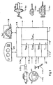
- 1 shows various sources for setpoint specifications.
- 1-17a-c designate various sensors, according to which target accelerations are generated.
- 1-17a denotes a distance sensor with which the distance to the vehicle in front is determined.
- a vehicle sequence control 11a determines a vehicle acceleration a sequence which is suitable for the vehicle sequence control .
- 1-17b symbolize buttons that are located on the steering wheel or a steering column switch with which the cruise control can be influenced.
- the keyboard can have keys for setting, increasing, decreasing or resuming a specific target speed.
- the cruise control 1-11b determines an acceleration a temp desired to achieve its control objective.
- pedals 1-17c (brake pedal and accelerator, possibly clutch), a driver can directly influence the vehicle as desired.
- a suitable control 1-11c determines an acceleration a pedal from these variables and from other operating conditions.
- Reference number 1-11d symbolizes further sources of intermediate acceleration values, for example a curve speed adjustment or a driving stability control.
- This acceleration a Lsoll is input to an acceleration controller 1-13, which actuates the various vehicle actuators such as brakes 1-14a and / or transmission 1-14b and / or motor 1-14c according to this requirement.
- the coordinator device 1-12 can have various configurations. In a simple case, the coordination device 1-12 is designed in such a way that it outputs the smallest of all the values entered to it as the setpoint a Lsoll to the acceleration controller 1-13. "The smallest value" is to be understood in the mathematical sense, ie taking the sign into account.
- the coordination device 1-12 can, however, also form a weighted average from the values received by it, it being possible for the weights to be adapted or shifted depending on the situation.
- the state variables in and around the vehicle are detected by sensors 1-16 and 1-17a-c. The values supplied by these sensors can be used to control the weighting or the selection of individual target acceleration values entered by the coordinator device 1-12.
- the individual components 1-11a-d generating setpoints lie and work functionally parallel to each other. This makes it possible to give the individual components different characteristics without such characteristics being blurred by subsequent components. For example, it is possible to set the cruise control to "soft", while the distance sequence control can be set to "immediate”.
- the coordinator device 1-12 can then, for example in the case of competing signals from cruise control 1-11b and vehicle sequence control 1-11a, select the acceleration a sequence output by the vehicle sequence control 1-11a and supply it to the acceleration controller 1-13 as acceleration a Lsoll without the "immediate” characteristic of the vehicle sequence control being blurred again by the "soft" characteristic of the cruise control 1-11b.
- the output result of the vehicle sequence control would be evaluated by the downstream cruise control and thus possibly washed out.
- the components 1-11a - 1-11d that generate the setpoints are not limited to the examples above.
- vehicle control can include other components are added, which generate individual target values. she can run in parallel to the other components that already exist be switched and coordinated by the Coordinator device 1-12 are included.
- control and security logic 1-18 monitors, which ensures the control process and appropriate measures if individual components fail like partial shutdown, full shutdown or similar grasps.
- a Adaptation of different characteristic curves to different driver classes about monitoring driver behavior, the Vehicle reaction and the environment is also possible.
- the control and safety logic 1-18 monitors also user interface 1-15 by using your appropriate Signals are supplied and received signals received from it become.
- Another aspect of the present invention relates to a Method and device for vehicle sequence control.
- Curve 3-10 shows the speed of a vehicle in front, curve 3-11 the speed of an immediately following vehicle.
- the starting point is now the steady state, in which the two vehicles drive one behind the other at constant speed v 0 . It is then assumed that the vehicle in front brakes at time t 1 and then continues at reduced speed v 1 . From time t 1, curve 3-10 thus shows a drop in speed from v 0 to v 1 . This results in a state that the speed of the following vehicle (curve 3-11) is higher than the speed of the preceding vehicle (curve 3-10) from time t 1 . In order to prevent the rearward collision, the following vehicle must also brake sooner or later. Now the following vehicle cannot immediately follow the speed change of the preceding vehicle.
- time t 4 Up to time t 4 , at which the speed of the following vehicle has adjusted to that of the preceding vehicle, the speed of the following vehicle is higher than that of the preceding vehicle. Therefore, the distance between the two vehicles decreases until time t 4 .
- the reduction in distance corresponds to the area (integral) between the two curves.
- the following vehicle is braked further. This is usually done by reducing the speed until the original distance or a distance corresponding to the new speed is restored between the two vehicles. In Fig. 9 this is assumed at time t 5 .
- ICC regulation Intelligent Cruise Control
- one ICC regulation has response times that lead to that there are distances between vehicles running behind one another decrease when the vehicle in front brakes. Such reductions in distance are achieved by braking of the following vehicle below the minimum speed of the vehicle in front, as referenced described in FIG.
- the object of this aspect of the invention is a method and to specify a device for driving speed control, with the effects of response or delay times be reduced or avoided.
- the controller 10 shows a distance controller. It receives input signals, that of a comparatively sophisticated one Sensors are supplied. Among other things, it receives signals the distance and relative speed of your own Vehicle from or in front of a vehicle in front Specify vehicle. The controller also knows its own Speed. The controller is designed, at least the above input signals control signals for the to produce your own vehicle. These control signals can Control signals include both acceleration as well as braking the vehicle. An acceleration of the vehicle can be achieved by the Distance controller outputs signals that, for example, the digitized Correspond to signals from an accelerator pedal. This Output signals are then from a subsequent engine control processed in a suitable manner. Just as direct are Control signals for the throttle valve conceivable, if necessary in connection with signals for the injection duration, to directly increase the speed. Via accelerator pedal and throttle signals can also be a decrease the vehicle speed are caused (engine brake). In addition, the ICC controller can output signals that an active braking of the vehicle by the Brake system is controlled directly or indirectly.
- Fig. 11 shows the case that the ICC control the speed of the following vehicle (Curve 3-31) regulates so that the braking of the vehicle in front Vehicle also braked with a time delay will, but the speed of the vehicle in front is not undercut.
- FIG. 11 shows the control aim of not letting the speed of the following vehicle drop below the speed of the preceding vehicle.
- the speed of the following vehicle (curve 3-31) is higher than the speed of the preceding vehicle (curve 3-30).
- the distance between the two vehicles thus decreases between the times mentioned.
- the reduction in distance corresponds to the integral over the relative speed.
- the reduction in distance is shown in the lower part of FIG. 11. In the upper part the reduction in distance corresponds figuratively to the area between curves 3-30 and 3-31, in the lower part the value is marked as - ⁇ .
- the distance between the two vehicles between t 9 and t 10 has decreased by this value - ⁇ .
- Fig. 11 shows the case in which the preceding vehicle accelerates again (time t 11 ).
- the ICC control can be designed such that it does not immediately follow the acceleration of the vehicle in front, but only with a time delay at time t 12 .
- the following vehicle is then accelerated until it has resumed the speed of the preceding vehicle at time t 13 .
- the distance is then preferably the same as before time t 9 .
- the time offset t 12 -t 11 between the driver's own acceleration and acceleration of the preceding vehicle is preferably as large as the time offset between the beginning of the braking of the preceding vehicle and the beginning of the braking of the following vehicle.
- the ICC control can be designed such that it specifies the target speed of the following vehicle so that it is slightly below the speed v 1 of the preceding vehicle. This somewhat reduced speed is preferably specified only after a certain period of time has elapsed after the lower constant speed v 1 (time t 10 ) has been reached. This reduced default speed is maintained until the desired distance between the vehicles for the speed v 1 is reached.
- the ICC control can also be designed in such a way that, in the event that braking of the vehicle in front is detected, it allows briefly comparatively smaller distances than in the stationary state between the two vehicles. This permitting of shorter distances can also be taken over for a period in which the vehicle in front has reached a constant lower speed after braking. In FIG. 11 that would be the speed v 1 from the time t 14 .
- the minimum distances permitted in the steady state or the minimum distances permitted in dynamic transition states can be speed-dependent and can be stored in tables or maps.
- the distance actually intended for steady-state conditions can be set by braking one's own vehicle slightly until the distance between the steady-state condition and, if applicable, the corresponding speed, between the both vehicles are set again. Then you can accelerate until the two vehicles have the same speed.
- the regulation described above can be made by a suitable programmed computer to be implemented using the above takes the input variables mentioned and also described Control signals delivers. Such systems are time-discretely sampled, the signal processing takes place digital.
- Another aspect of the present invention relates to a Method and device for generating a Vehicle speed indicating speed signal.
- control becomes an accurate speed signal needed. So far the speed signal either delivered directly from a sensor or one Output taken from an ABS control. Such signals are but heavily overlaid with noise, so that in some Applications, e.g. in ICC systems, not easily can be used.
- the object of this aspect of the invention is a method and to provide a device with which an accurate speed signal received with little delay can be.
- noise does not disturb the speed signal evenly distributed over the frequency range, but that there are individually distinguishable interference components.
- the inventors found that, on the one hand, parts that can be localized by a frequency band and, on the other hand, higher-frequency parts disturb the speed signal.
- Fig. 12 shows the spectrum of a speed signal, as is usually used for engine or vehicle control.
- Such disturbances have a significant influence on the accuracy or reliability of the vehicle control and must therefore be suppressed.
- FIG. 13 shows a block diagram of an embodiment according to the invention for suppressing disturbances in the speed signal.
- the disturbed input speed signal v E passes through a low-pass filter 4-20 and a band-stop filter 4-21. Both filters 4-20 and 4-21 need not be provided. One of the two may be sufficient, the connection in series, possibly in the reverse order, leading to very good results.
- the fact when filtering the input speed signal v E, the fact must be taken into account that the acceleration of the vehicle can lead to amounts of speed change in the disturbed input signal that are comparable in size or greater than disturbing ripple components in the signal. Such components must not simply be filtered out, otherwise the filtered signal would not reproduce the speed correctly or only with a time delay.
- FIG. 14 shows an embodiment of the low pass 4-20 according to the invention.
- it is a first-order low-pass filter PT 1 . It is formed by the gain K 30 and the integrator 1 / s 4-31.
- a gradient restriction 4-32 specifies the extent to which changes in the input speed signal v E can move.
- the gradient limitation is understood here and below to mean the limitation of the rise and fall speed of a signal. The problem arises here that during accelerations these changes can lie far above the level of ripples. Without further measures, the filter would cut off parts of the useful signal.
- Another PT 1 element 4-33 is therefore connected in parallel with the gradient limitation 4-32. The PT 1 element provides an offset which is added to output the gradient limitation 4-32. This ensures that the permitted ripple is carried along with the acceleration level present in each case.
- the corner frequency of the further PT 1 element 4-33 is preferably higher than that of the overall transmission of the low pass 4-20.
- the interference frequency is simulated on the one hand (serial integrators 4-43 and 4-44 and negative feedback 4-45).
- the simulated interference frequency ⁇ 0 is subtracted from the input speed signal v z at point 4-40. This subtraction produces the output speed signal v A , which is also fed back into the simulation of the interference frequency ⁇ 0 via blocks 4-41 and 4-42.
- the output speed signal v A is fed back into the simulation of the interference frequency ⁇ 0 in such a way that the signal is fed via adjustable gains K 1 and K 2 and is additionally fed in before the input of the series-connected integrators 4-43 and 4-44. In this way, the interfering frequency band is filtered out, the circuit according to FIG. 15 appears as a bandstop.
- the filtering of the raw signal v E proposed according to the invention produces a speed signal v A which is well suited for further processing. Higher frequency components are not filtered out indiscriminately. Such indiscriminate filtering would result in accelerations of the motor vehicle, which are represented as higher-frequency components in the frequency range of the speed signal, would be smoothed out in the speed signal and would thus deliver a poorly adapted signal or signal that slowly follows the actual conditions.
- the embodiment of the low-pass filter with gradient limitation 4-32 and offset feed 4-33 results in a non-linear filter with which acceleration levels permitted despite filtering out ripples are reliably or quickly mapped in the filtered signal.
- the corner frequency of the low-pass filter is constant and is determined in comparison with linear filters of different corner frequencies.
- the described bandstop filter according to the invention can be adapted to the prevailing conditions via the feedback of the output signal v A via the factors of K 1 and K 2.
- FIG. 16 shows the spectrum of a speed signal, that pass through a bandstop according to FIG. 13 or FIG. 15 Has. It is clearly recognizable that the disturbance at approx. 2 Hz is fixed.
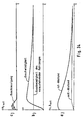
- FIG. 17 and 18 show the overview or in detail Output signal of the non-linear filter according to the invention compared to the output signal from the ABS control and compared to linear filters of different corner frequencies.
- Fig. 17 is a driving course with accelerating, braking and with a phase of uniform speed (Constant travel at about 7 seconds) over a period of about 25 seconds. As an enlarged section this driving course is the time segment in FIG maximum speed applied during the 25 seconds.
- the most noisy signal is the output signal an ABS regulation. This signal is that too Input signal for all additionally shown filters.
- Denoted by NL is the output signal of the invention non-linear filter shown. It is very much smoother than the ABS signal. Furthermore are for comparison the output signals of linear filters with different Cutoff frequencies (2 to 10 Hz) specified.
- the non-linear filter has a lower corner frequency (4 Hz) than some of the linear filters.
- the Loss of amplitude of the filter according to the invention is the same of a linear 8 Hz filter.
- the ripple of the invention non-linear filter is roughly the same as one linear 2 Hz filter comparable.
- Another aspect of the present invention relates to a Method and device for vehicle control. He relates in particular to vehicle control systems in which Target speeds are specified, which are then by a downstream control can be set. Such speed settings can for example by Cruise control takes place. Such cruise control can be comparatively be of a simple nature. They then consist of different ones Switches with which set speeds are set, increased, decreased, deleted or resumed can. Cruise control can also be combined with more complex ones Regulations are used. Such regulations are known as ICC (Intelligent Cruise Control). In such Regulations will not only speed the vehicle regulated according to driver requirements, but also according to Providing information, the sensors from the vehicle environment have recorded. Distance sensors would be a priority here to name the distance to possibly leading vehicles Determine vehicles. In addition there are sensors conceivable, for example, the road conditions check.
- ICC Intelligent Cruise Control
- the regulations described above work in accordance with the Driver will and according to information provided by Sensors inside or outside the vehicle can be detected. In many cases, they create a reference variable Set speed. Vehicle accelerations can also work just as well or distances to vehicles in front be specified as reference values. In any case it may be that these benchmarks for one Driving unpleasant operating conditions of the vehicle, for example to abrupt accelerations, sudden Braking or jerky driving of the vehicle. This can happen especially if there are sudden changes in the predetermined target speed. Such target speed changes are so far unrated in the Regulation added as a benchmark. So that The above-mentioned unpleasant driving conditions are not sufficient can be prevented well.
- the object of this aspect of the invention is a method and a device for vehicle control specify with which a comfortable and jerky driving becomes possible.
- the target speed jump is smoothed.
- the smoothing is carried out by a suitable device.
- the combination of the devices 5-10, 5-11 and 5-12 is shown by way of example in FIG. 19.
- the circuit shown is a low-pass filter.
- the device 5-11 can be a reinforcement. It is followed by an integrator 5-12.
- the output variable of the integrator in the example shown results in the PT 1- evaluated course of the entered target speed course. The sharp rise in the target speed is thereby mitigated and unpleasant driving conditions of the vehicle are avoided.
- a PT 1 link does not necessarily have to be provided as the low pass, but PT 2 links or general low passes can also be used.
- a further safeguard against unpleasant driving conditions can be achieved if a gradient restriction is introduced for the target speed.
- a gradient restriction can be introduced separately or in conjunction with the low pass described above (for example PT 1 or PT 2 element).
- the effect of the gradient restriction is first described with reference to FIG. 20.
- the gradient here is the change in the target speed per unit of time. Physically, this is an acceleration. 20 shows the strongest gradient shortly after the beginning of the rise of curve 5-21. It is symbolized by the tangent 5-22. Your slope corresponds to the gradient. The greater the jump in the target speed, the steeper the steepest rise in curve 5-21 will be. There may be situations in which the rise becomes too steep despite filtering. In the end, the same disadvantages then result as in the ideal jump of the target speed assumed at the beginning.
- the gradient - the slope of the tangent 5-22 - is limited to a certain value, which is not exceeded regardless of the size of the jump in the setpoint speed. In one embodiment, this can be done by a separate circuit. 19 shows a further embodiment. There the reinforcement 11 is provided with a restriction. The amplification thus has a characteristic similar to FIG. 21. The difference originating from the device 5-10 is thus only amplified up to a certain maximum value. Via integrator 5-12 and feedback, this leads to the desired gradient limitation being achieved.
- the gradient restriction can be for positive and negative Acceleration can be set differently by different Kinks in the characteristic of FIG. 21 can be set. It may also be desirable allow manipulation of the gradient constraint. If, for example, according to the driver's request - entered for example by pressing the acceleration button several times - strong acceleration desired higher gradients can be allowed, for example by only in this case the kinks in Fig. 21 pushed further away from the origin. Then they are steeper Increases of the specified target speed possible, and the vehicle accelerates faster. The driver, if caused by him, this change in the gradient restriction arises as a direct response to his actions represents.
- a function generator 5-15 receives the difference between the output of the low pass 5-10 - 5-12 and the actual vehicle speed.
- Function generator 5-15 thus receives a value that corresponds to the difference between the filtered target speed and the actual speed. As output, it delivers an acceleration that can be used as a reference variable in accordance with the function it represents. In contrast to FIG.
- FIG. 19 shows an embodiment in which in the adder 5-6 a feed forward portion for output of the function generator 5-15 is added using a filter 5-18 is generated from a signal between amplification 5-11 and integrator 5-12 was tapped.
- the characteristic of the filter 5-18 can have a gain as well as system characteristics be incorporated so that through use of the feed-forward part a very spontaneous reaction to the driver's specification while maintaining the comfortable Controller dynamics becomes possible.
- a device 5-19 Long-term observation of driver activities. For example can frequency, duration and size of accelerations and delays are detected. Such grasped Values can then be classified (for example, "quieter Driver "," sporty driver "). In accordance with this Individual parameters in the system can then be classified be modified.
- the device 5-19 can in the system of 19, for example, the gradient restriction 5-11 Feed-forward filter 5-18 or the function generator 5-15 influence.
- a setpoint speed specified, for example, by the function generator 5-15 can be limited to certain absolute values, for example -1.0 m / s 2 , +1.5 m / s 2 . If the driver briefly exceeds the speed set by the cruise control using the accelerator pedal, for example when overtaking a truck, the controller is switched to standby due to the driver intervention. After stepping over, i.e. after the overtaking process has ended, the vehicle brakes to the speed set by the cruise control. So that this braking does not become too strong, for example to avoid braking of the vehicle that has just been overhauled, the limitation of the acceleration specified by the function generator 5-15 can be reduced, for example to -0.7 m / s 2 , +1.0 m / s 2 . In general, such border changes can be made after driver interventions. If the requested acceleration is then below the set limit value, the original limit values, which are higher in terms of amount, can be reset.
- Another aspect of the invention relates to a method for "smooth" control of a hydraulically operated brake in the "sliding mode” method and a device for Performing this procedure.
- the object of this aspect of the invention is therefore a method and to provide a device with which the required Processor performance reduced to a low level can be.
- the method is characterized by outputting a pressure build-up signal and a pressure reduction signal to means for adjusting the braking pressure to the brake to achieve a target pressure P.
- the means for setting the brake pressure are two digitally switching valves which are connected to the pressure generator or the pressure reservoir, the unpressurized reservoir and the brake cylinder (recipient). One valve connects the pressure reservoir to the brake cylinder, the second valve connects the unpressurized reservoir to the brake cylinder.
- the required pressure in the consumer (recipient) is set by appropriately clocked opening and closing of the digitally switching valves.
- another embodiment is characterized in that the first valve can be dispensed with if the finite volume flow from the pressure generator through the supply lines is taken into account. Then the pressure reduction through the second valve (immediately before the unpressurized reservoir) only has to be permitted for a short time.
- a target volume flow Q to from the desired brake pressure P soll and a gauge pressure p measured at the valves corresponding actual pressure p is determined on a brake cylinder.
- the actual pressure p ist in the brake cylinder is determined by a pressure observer from the measured pressure p mess at the valves.
- the model on which the print observer is based is taken into account besides the pressure difference between measuring point and Brake u. a. the impedance of the feed lines on the Working fluid acts.
- the impedance and the pressure difference determine the volume flow through the supply lines, d. H. the volume flowing through the supply lines per unit of time.
- the volume flow can in particular be directly proportional on the impedance and otherwise on the root of the Depending on the pressure difference between the measuring point and the brake. at known volume over a period of time in the Brake cylinder has flowed, so the brake pressure is known.
- the brake pressure depends on z. B. square of that Volume of the brake cylinder.
- the root dependency of the volume flow from the pressure difference replaced a linear dependency
- the working point of the control loop must be chosen so that in both directions no major deviations occur. This is of course only possible over a limited working area.
- the signals for controlling the volume flow also be filtered before being output to the valves. This is done in a separate control loop, the above is virtually downstream.
- This type becomes the set volume flow and the actual volume flow Control signals for the digital valve or the digital valves according to the so-called sliding mode control principle generated. Both the pressure build-up signal and the pressure release signal are thus from the target volume flow and a the actual volume flow corresponding to the measuring pressure is determined.
- the time derivation of the actual volume flow be taken into account.
- the inertia of the Working fluids or the valve used In other words, the pressure itself is no longer regulated, but regulation takes place exclusively via the control of the Volume flow of the working fluid.
- a target pressure p target is entered for the brake system as a default.
- This first control circuit comprises a subtractor 6-1, a pressure regulator 6-2 and a pressure observer 6-3.
- the pressure observer 6-3 determines on the basis of a measured measuring pressure p mess in the hydraulic system 6-6 an actual pressure p which is subtracted from the target pressure p soll at the input of the control circuit, the difference then being processed by the pressure regulator.
- the pressure regulator also reports further states to the pressure observer with which the model of the pressure observer can be compared.
- the output of the pressure regulator is a signal corresponding to the flow rate Q, which must be produced to achieve the required braking pressure.
- This signal Q soll is converted by a volume flow controller 6-4 into control signals for one or more (not shown) digital valves 6-7 and 6-8 in the hydraulic system 6-6. The order and generation of these signals will be explained later in connection with FIGS. 26a and 27.
- the pressure observer 6-3 determined on the basis of the measured pressure in the hydraulic system 6-6 p measuring the actual pressure p.
- the pressure observer can also be a control loop.
- the control loop output is p is determined from the input variable p measured in negative feedback.
- a quantity p is subtracted from the measured pressure p mess in a subtractor 6-9 analogously to the structure of the first control loop in FIG. 23.
- the difference between these two signals is further converted by a first multiplication element 6-10, a first integrator element 6-11 and a first characteristic element 6-12 into an actual pressure p ist .
- Several independent models can be used as a basis; the model of the control loop in this embodiment is based on the image shown in FIG. 25. Both a value that corresponds to a pressure and a value that corresponds to a volume flow can serve as the actual output variable.
- the pressure of a (sub) system is preferably measured in the immediate vicinity of the central control devices.
- this has the disadvantage that changes in pressure due to influences by the pressure line are not detected.
- this can be countered with a model that takes known influences of the pressure lines into account and determines the values actually prevailing at the end of the line from the values measured at a central point.
- a model is based on the control elements 6-9 to 6-12 and is shown in FIG. 25.
- the properties of the supply line 6-13 for the working fluid are summarized as impedance D v 6-14.
- the supply lines end on the brake 6-15 in a brake cylinder (not shown), the volume of which is V.
- the measured pressure is recorded immediately behind a valve (not shown) for regulating the volume flow by a pressure sensor 6-16 and transmitted to the pressure observer 6-3.
- the brake pressure or actual pressure at the brakes p ist can be estimated from the current or current volume flow Q ist to the brake cylinder.
- the pressure regulator 6-2 itself needs as shown in Fig. 24 to be just a simple curve element that ever after entering a volume flow that is as already described above by a volume flow controller 6-4 in signals is implemented for digital valves 6-7 and 6-8.
- a "linearized" pressure observer can be used.
- Such a linearized pressure observer is shown in FIG. 26b, and for comparison in FIG. 26a a non-linear pressure observer, as in the embodiment according to FIG. 24.
- the structure in FIG. 26a is in principle the same as in FIG. 24 with the same Elements, namely subtractor 6-9, multiplier 6-10, integrator 6-11 and characteristic element 6-12, only that here, unlike in the embodiment described above, instead of the brake pressure p , a volume flow Q represents the output variable.
- the multiplier 6-10 has been replaced by a first proportional element 6-17 and the characteristic element 6-12 has been replaced by a second proportional element 6-18.
- the function of the pressure monitor 6-3 is identical in both cases.
- the output signal of the first control circuit in FIG. 23 with pressure regulator 6-1 and pressure observer 6-3 can be converted directly into control signals for the digital valves 6-7 and 6-8 by a volume regulator 6-4.
- a volume flow monitor 6-5 is used.
- the control loop, which is to the volume flow Q sets, is constructed as a negative feedback circuit whose input is the output of the first control circuit. (The output quantity must be a volume flow signal in this case.)
- a value Q ist is subtracted from the output signal of the first control circuit Q soll , which value was generated by the volume flow observer 6-5.
- the volume flow observer has this value based on the measured pressure p meas determined which already input value for the actual pressure p was due to the pressure observers.
- the general structure of this second control circuit for setting the switching signals for the digital valves 6-7 and 6-8 in the hydraulic system 6-6 is obvious to the person skilled in the art and need not be explained further here.
- the volume flow observer 6-5 is a first DT 1 element.
- the output signal corresponds to the actual flow rate Q, the target from the target volumetric flow Q, the output from the first control circuit in Fig. 23, is subtracted at the input of the control loop. This is shown in the right part of FIG. 27.
- the signal Q is present at the inverting input of the two subtractors 6-19 and 6-20.
- it is present at the input of a second or third DT 1 element, the output of which is inverted and is connected to the output of one of the subtractors 6-19 and 6-20, so that a composite signal s results in each case.
- This composite signal s is applied to a characteristic element 6-23 or 6-24.
- the characteristic element 6-23 or 6-24 outputs a valve control signal SO or SG for the two digital valves 6-7 and 6-8, which opens or closes them, depending on the input variable. So that there is no hydrodynamic or pneumatic short circuit, the characteristic curves in the characteristic curve members are selected so that simultaneous opening of the digital valves 6-7 and 6-8 is impossible. Specifically, this means that the zero crossing of the two characteristic curves in the characteristic elements 6-23 and 6-24 takes place at different sizes of the signal s and, over the entire range through which the signal s can pass, there results a switching behavior of the valves, which is a hysteresis like.
- the "sliding mode" control process takes place in this embodiment with high pressure hydraulics as follows.
- the quantity Q should increase and thus leads to a control error in the volume flow controller 6-4.
- This deviation is converted into a switch-on pulse for a digital valve 6-7, an SG valve, whereupon the current in the coil of the valve increases.
- the valve After overcoming the restoring forces and frictional forces, the valve begins to open and the measured pressure at the valve 6-7 increases. This also increases the current volume flow Q ist . If the control condition is fulfilled, ie the signal s in FIG. 27 falls back to zero, the valve is switched off and the current drops. As a result, the valve stops the opening movement, and the value Q is reduced again or at most increases very slowly.
- control signals s which in FIG. 27 are the input signals of the characteristic elements 6-23 and 6-24 are very output at high frequency if expression (1) is 0 will disappear. But if s> 0, the valves must 6-7 and 6-8 are switched so that pressure builds up stattindet. On the other hand, if s ⁇ 0, pressure must be reduced through the valves 6-7 and 6-8.
- a certain Quiet zone in the valve control between issuing a SO control signal and an SG control signal guaranteed - As already described above - the certainty that not both valves can be activated at the same time. on the other hand can also open both valves for a short time be achieved, which ensures that the ripple in the pressure build-up is minimized in the recipient.
- FIG. 28 The structure of the printing system in which the invention Pressure control is used is shown in Fig. 28.
- a pressure is built up by a pressure generator 6-25.
- the pressure generator is usually one Pump with a motor as a drive.
- the pressure cycle will by check valves 6-26 and 6-27 upstream or aligned downstream of the pressure generator 6-25 in one sense. Downstream from the pressure generator 6-25 and the First check valve 6-27 is the SG valve 6-7. Should pressure build up downstream of this valve 6-7 If the condition s> 0 is fulfilled, then this valve is controlled by the characteristic element 6-24, so that it opens.
- the pressure is immediately behind the valve 6-7 measured by the pressure sensor 6-16.
- a valve can be dispensed with.
- This embodiment is shown in Fig. 29. This is where the pressure generator works 6-25 constant against a pressure in the brake system while the SO valve 6-7 opens again and again, so that the pressure one does not exceed the specified value. For the rest is the operation of this embodiment is the same as that discussed above. Analogously, the pressure generator can also like the SG valve can be activated.
- the printing system can be used for any braking system and Brake distributions applied to the wheels of a vehicle become.
- Another aspect of the invention relates to a method and a device for the smoothest possible transition between two driving conditions.
- a method and device for jerky stopping an object is known from DE 34 34 793.
- Object the current speed and the current delay of the object is detected.
- a deceleration setpoint is calculated.
- the deceleration setpoint is compared to the current delay, and a corresponding difference signal is generated.
- the braking device is controlled so that the Differential signal becomes minimal and the current delay is adjusted to the deceleration setpoint.
- a "jerky Stop "is desired then a calculated deceleration setpoint output, the delay being proportional to a function of speeds.
- the Deceleration setpoint is approximately zero when the current one Speed goes to zero.
- the solution to the above problem is based on the calculation the transition accelerations by means of variation calculation.
- the result of the variation calculation is an algorithm the optimal course of time in the above sense of the Provides driving status during the transition phase. It can the duration of the transition phase a predetermined, constant Be worth or be a function of at least one of the above driving parameters.
- the actual state is defined by the current location, the current absolute speed, the current acceleration and the current driving parameters which define the driving state in a further reference system.
- the corresponding parameters are thus the distance (to the vehicle in front), the relative speed (in relation to the vehicle in front) and the relative acceleration (in relation to the vehicle in front).
- the target inventive acceleration is determined by the method according to the invention, which accelerates smoothly from the current driving state with the unsuitable distance changes into a target driving state with the desired distance.
- a time-dependent acceleration function defined over a predetermined time interval is determined in such a way that its integral is minimal over the square of its time derivative, the start and end states being defined.
- this would be, in particular, knowledge of the current distance to the vehicle in front and the definition of a target distance to the vehicle in front.
- Procedure will use the acceleration function that the above Minimum condition met, from a set of predefined functions selected, which limits the search space somewhat can be. This is of particular interest to the numerical evaluation of the cheapest acceleration function, because the functions to be searched are limited Storage must be accommodated. in this connection can then be used depending on the variation calculation Problem, for example, the number of functions to be searched on quadratic functions dependent on time be restricted. As a quadratic dependency, however may not lead to the desired goal, functions may also have to be taken into account, which depend cubically on time. In both cases the stored functions can be parametric from the specified transition time to reaching the target state and / or from the target distance and / or from the actual state and / or depend on the target state. Finally, the transition period still depend on driving parameters.
- the vehicle under consideration in which a device for implementing the method according to the invention for controlling the longitudinal movement of the vehicle is installed, travels the distance x (t) in time t.
- the distance s (t) to the vehicle in front is measured continuously. This is done using known distance sensors, such as radar or ultrasound or laser sensors. The distance measurement itself can then be carried out with a sequence of pulses which are emitted continuously by the sensor and are collected by a detector connected to the sensor.
- continuous signals can also be used, which are particularly useful if the changes are also to be recorded continuously. While this is only possible in pulse mode by measuring the time differences from pulse to pulse, ie discretely, the frequency shift of the signal due to the relative speed can be used for the continuous signal.
- the absolute value of the distance can only be determined with a continuous signal via triangulation or the like.
- the driving state defined by the above six-sector must therefore change to a driving state defined by the following six-sector:
- the transition must be such that the integral in the equation 90/1 becomes minimal. Specifically, that means that Square of the rucks is minimized. By squaring the the function to be integrated is independent of this whether the transition acceleration is a positive or negative acceleration. The means that if a solution to this problem with the constraint, given by the six servectors from above is found, so the problem with both Braking as well as when the vehicle gets faster. In addition, it must also be noted that the limits of integration for the calculation of the integral become. However, it is possible that these limits of integration be continuously adapted to the current driving condition. In other words, the transition time t can be practically free to get voted.
- this is the procedure to determine the optimal acceleration function if from an initial state with a predetermined distance, more predetermined Relative speed and predetermined relative acceleration as well as predetermined speed and predetermined Acceleration of the vehicle can be transferred should be in a final state with a predetermined target distance to the vehicle in front.
- this is a special one Problem, its mathematical treatment here, for example was reproduced.
- There may be other transition conditions such as the transition from a current speed to a target speed or target relative speed and a transition between an instantaneous acceleration and a target relative acceleration or target acceleration, their calculation essentially according to the same principles as described above.
- step 7-S1 This value in the memory represents the integral that is to be minimized is a - in step 7-S1 - fictitious function with which the functions selected in the following steps become.
- a function becomes one Functional space selected, processed below and to be compared with the above fictional function.
- the memory can be a number of Contain zeros of first degree polynomials, where then the desired function by multiplying the several First degree polynomials arise depending on the desired one highest potency of the function.
- the memory also exponential functions in the form of their decay coefficients include.
- the selected function is after time differentiated and then squared.
- step 7-S4 the function between the limits 0 and t e , ie the end of the transition phase, is finally integrated.
- t e is initially a fixed value. However, this can be adapted to the respective target speed and / or the respective target distance and / or the absolute speed and / or the current distance as required in the course of the method.
- step 7-S5 the value of this integral becomes the value compared in the memory from step S1. Is the value of the integral less than the value that is in the memory, so the method continues with step 7-S7, in which the function in the form of its parameters in a function memory is saved.
- This functional memory is built similar to the functional space in step 7-S2, only that this memory is only set up for one function.
- step 7-S7 it is checked whether the running parameter a predetermined value equal to the upper limit of the functions to be tested. This comparison takes place in step S6.
- step 7-S5 when comparing the immediate previously evaluated integrals with those stored in memory Value determined that the value stored in the memory is smaller than the integral value, the method also runs proceed immediately to step 7-S6, bypassing Step 7-S7.
- step 7-S6 If it is determined in step 7-S6 that the running parameter n has not yet reached the maximum value n max , the method jumps back to step 7-S2 and a new function is selected from the functional space by incrementing the running parameter n. If, however, it is found that the running parameter n is already equal to the maximum value n max , the function stored in the function memory is output as a result in step 7-S8. The process flow ends in step 7-S9, which follows step 7-S8.
- the optimal acceleration function represents, for example, a third degree polynomial, the coefficients of the polynomial being parametric from the predetermined transition time t e to reaching the desired state and / or from the current desired distance and / or depend on the current relative speed and / or the current relative acceleration and / or the current absolute speed and / or the current absolute acceleration.
- “currently” means the beginning of the transition phase.
- the independent quantity t can be set equal to the sampling time in digital processing for a discrete vehicle longitudinal controller, so that the optimum acceleration value for the coming sampling point in each case is obtained. If you want to use linear filters to determine the optimal change in acceleration, you can do this for a continuous vehicle longitudinal controller by replacing equation 7/9 with a series expansion and aborting it after the linear term.
- the device comprises a differentiating element for differentiating a selected function, the output of which is connected to the input of a square element for squaring the differentiated function. This square element multiplies the function by itself and then outputs it to the input of an integrator.
- the control device comprises a comparator for comparing the output value of the integrator with the numerical value stored in the memory and also for outputting the optimal acceleration function found.
- Another aspect of the invention relates to a method for distance control with virtual springs and dampers, thus with artificially generated dynamics in the process of raining a distance to a vehicle in front, and an apparatus for performing this method.
- the security system described there includes a distance sensor to determine the distance ahead Vehicles and a program-controlled computer for processing the signals from the distance sensor and output corresponding control commands.
- the ultrasonic distance sensor works on the runtime principle.
- the computer differentiates the measured value from the distance sensor according to the Time and activates a warning device or brakes it Vehicle off when the relative speed is so high and the distance becomes so small that without braking a collision is inevitable.
- Another example for such a security system is known from US 5 165 497.
- E-gas i.e. the electric controllable engine torque
- active brake an electrically operated brake
- the object of this aspect of the invention is therefore a method and to provide a device with which the undesired strong speed changes of the vehicle to avoid.
- the method is characterized by outputting a target sequence acceleration to achieve a desired distance A is a preceding vehicle, the abgNeill s, the relative velocity v rel and the absolute velocity v abs of the instantaneous distance.
- the instantaneous distance s here means the distance to the time at which the output of the target follow-on acceleration a Fsoll takes place.
- the target following acceleration a Fsoll is the sum of a first component f, which depends on the instantaneous distance s from a vehicle in front, and a second component g, which depends on the relative speed v rel compared to a vehicle in front.
- the target following acceleration a Fsoll is determined as the sum of three components.
- the first summand or the first component is a term that depends on the distance s. In particular, this distance-dependent term can be proportional to the second derivative of the distance over time, but it can also depend directly on the distance.
- the second summand or the second component depends on the relative speed v rel . In particular, the second summand is proportional to the relative speed.
- the third summand finally depends on the absolute speed, that is to say the speed of the following vehicle, that is to say the vehicle in which the system according to the invention is installed.
- a Fsoll is the acceleration specification or the target follow- up acceleration value
- a (s) a term dependent on the distance, which is in particular proportional to the second time derivative of the distance s between the (following) and the preceding vehicle
- v rel and v abs are those Relative or absolute speed of the (following) vehicle compared to the preceding vehicle or the road.
- the coefficients b and c are weighting factors.
- the simplest version is the dependency of the coefficients linear from the relative speed. It can also vary depending on the coefficient Dependence of the coefficients on the relative speed to get voted. This is particularly useful if if the weighting of the individual components or summands in the above equation (8/2) depend on the driving condition. In particular, it can be achieved that at small differential speeds of the "damper" between the two vehicles and at high differential speeds the "damper" between the vehicle and the road is determining for the target follow-up acceleration. The transition between the two cases can moreover when skillful Choice of the dependence of the coefficients on the Relative speed can be designed smoothly.
- Target following acceleration Due to the variable coefficients, the relationship between Target following acceleration and the relative or absolute speed no longer linear. This already applies to the very simple equation (8/2). In addition to the representation the target follow-up acceleration as a sum can, however of course find more complicated functions, other friction laws to achieve special effects based on what corresponds to non-linear springs and dampers.
- the procedure was numerically simulated and showed the expected Behavior: caused by the dead times between issue a target acceleration value without virtual springs and masses was calculated, and reaching the desired Acceleration of fanned vibrations in a column of vehicles were suppressed using the method according to the invention, there were no longer any regular deviations.
- FIG. 31 shows two vehicles 8-1 and 8-2 traveling in series, of which the rear vehicle 8-1 is the one in which the control according to the invention is installed.
- the two vehicles are connected to each other by a virtual spring 8-3 and a virtual damper 8-4.
- These two virtual coupling elements are adjustable so that the desired or desired distance between the two vehicles results, which is composed of a term dependent on the absolute speed and a so-called "offset" term A offset .
- the term dependent on the absolute speed can be represented as a product of a time and the absolute speed v abs .
- the time factor in the product is the time that would pass at the current absolute speed until the (following) vehicle 8-1 would collide with the stationary “preceding” vehicle (time to collision, T col ).
- the spring 8-4 acts in a certain way against the spring and thus prevents excessive deflections or vibration amplitudes of the system from two successive vehicles.
- the one output from the speed selector switch 8-6 Minimum distance d is given by the distance sensor 8-5 subtractor 8-7.
- the difference signal of the two distances from the subtractor 8-7 is the input variable of a spring characteristic element 8-9.
- this spring characteristic element 8-9 a first acceleration value corresponding to the input variable generated.
- the relationship between input variable and The output variable, i.e. the first acceleration value, is here usually non-linear.
- the spring characteristic element 8-9 is differentiated according to time Distance signal (in particular from a Doppler shift measurement can originate) from the distance sensor 8-5 to determine a second acceleration value used.
- time Distance signal in particular from a Doppler shift measurement can originate
- the time-derived signal used as the input variable of a damping characteristic element 8-8, that outputs a second acceleration value is also here. Also here is the relationship between input variable and output value usually non-linear.
- characteristic curves dependent on the absout speed are used in the method according to the invention; that is, the characteristic curve stored in each characteristic element depends parametrically on the current own absolute speed v abs .
- the two acceleration values are in an adder 8-10 added and then filtered and at their maximum Amplitude limited by a filter 8-11. This filtered and limited acceleration value corresponds to the Should result acceleration.
- the characteristic elements 8-8 and 8-9 are combined to form a characteristic element 8-12, so that with distance and relative speed from the distance sensor 8-5 as input variables from one quasi three-dimensional map, a corresponding value for the acceleration value can be read.
- the family of characteristic maps depends parametrically on the current absolute speed v abs of the vehicle.
- the embodiment according to FIG. 33 has the advantage that the adder 8-10 can be saved.
- 34 shows the course of important driving variables during the control phase.
- the target distance initially amount to 10 m. This target distance must be timed not constant, it depends essentially as already described depending on the current driving situation, in particular the speed of the vehicle in front, your own absolute speed etc.
- the speed can be set as shown in Fig. 34b is. It is assumed that the vehicle in front Vehicle 8-2 at a constant speed of 50 km / h drives. Now if the vehicle 8-1 is accelerated to reduce the distance to the vehicle in front 8-1, so changes as shown in part a of FIG Target distance depending on the absolute speed. Because the speed always depends on the current distance is tracked by the vehicle 8-2 in front, there are small fluctuations in the speed curve, which are a bit "higher frequency". These higher frequency parts in speed are then found in the acceleration signal in Fig. 34c again. They are clear there pronounced and show the reaction and tracking the target follow-up acceleration by the system according to the invention and procedures.
- Another aspect of the invention relates to an operating concept for a cruise control and in particular a Method for setting a target distance to a preceding one Vehicle through a distance controller, being the driver can modify the set distance. Moreover this aspect of the invention relates to a device to carry out the procedure.
- the target distance becomes too a preceding vehicle depending on the current one own speed determined.
- For distance control becomes a current distance to the vehicle in front Vehicle detected, an absolute speed detected, a first target distance from the current distance and the absolute speed betimmt.
- the Distance controller described there can be used for one of an engine driven first vehicle that is inserted into a Idle position for the engine preloaded power control element, a brake control element and a signal generator having.
- the signal generator generates to the distance of the leading second vehicle proportional first as well second control signals that fall below predetermined Clearances the power control and the brake control actuate. If the distance falls below a first dimension, the first actuator urges the power control element as the distance becomes smaller and smaller Spring force in the neutral position. If the distance falls below a second dimension, which is smaller than the first measure is and if the power element is around a the specified dimension is pushed into the idle position, the second actuator increasingly brakes the first vehicle with increasing distance. If the distance falls below a third dimension, which is smaller than the second Dimension is, so the signal generator to the second actuator third control signals for full braking of the first Vehicle and to a third actuator for resetting the power control to its idle position and to stop in its idle position.
- variable distance controllers are examined.
- this distance controller still under development currently with additional controls for the driver such as rotary knob or slider for entering the degree of undershoot of the safety distance experimented.
- This New controls have the disadvantage that it just "Additional" controls are, the function of which Driver must first understand.
- the object of this aspect of the invention is therefore a method and to provide a device with which the Driver can fall below the safety distance without the Distance controller must be switched off and without additional Controls are required.
- the method is characterized by the output of a second target distance A target when an accelerator pedal is pressed.
- warning signals are output acoustically and / or optically and / or haptically.
- the proposed measures will make it usable of the distance controller according to the invention better than that of Distance controller according to the state of the art, since it is used in all Driving situations, especially when there is a lot of traffic can stay on all the time and not how must be deactivated in the prior art if the Driver intends to stay below the safety distance.
- the behavior of the distance control according to the invention is transparent in that the operation of the Accelerator pedal leads to the fact that the own vehicle despite being switched on Distance control closer to the one in front as usual Vehicle approaches and when the accelerator pedal is released falls back again. The distance control always remains active and prevents a collision even with a reduced safety distance.
- Step 9-S1 i.e. activating the distance controller or the control device
- step 9-S2 the distance s recorded for a vehicle in front. This happens as is generally known with the help of a distance sensor, for example on the measurement of the ultrasound Laser or radar pulses or triangulation based on laser continuous wave signals.
- An absolute speed v abs of the vehicle is then detected in step 9-S3.
- the reference speed of an ABS system is preferably adopted for this purpose, but it can also be any other signal representing the speed of the vehicle, such as. B. the speedometer signal can be evaluated.
- step 9-S4 a first target distance A target is determined from the variables known up to this point, which depends on the absolute speed v abs .
- step 9-S5 it is determined that the driver is operating made an acceleration specification of the accelerator pedal has to fall below the first target distance would lead, this driver specification is recorded. This can the setting angle ⁇ of the accelerator pedal can be detected.
- step S7 a new 9-, second nominal distance A is determined 'and output.
- This new target distance A soll 'can depend on the setting angle ⁇ , for example linearly or via a previously stored characteristic curve.
- the second target distance is set in step 9-S8.
- step 9-S5 After the determination of the new target distance A soll ', the method jumps to the same point as after step 9-S5, where the method is continued if the driver has not made an acceleration specification.
- step 9-S9 checks in step 9-S9 whether the Distance control should be switched off. If this is the If so, the execution of the method jumps to the Address of step 9-S10 with which the method ends.
- step 9-S2 the method jumps back to step 9-S2 and moves on the detection of the current distance s to a vehicle in front Vehicle away. The others then close Procedural steps until the vehicle reaches its destination or the distance control is deactivated.
- Another aspect of the invention relates to a method for curve speed adjustment in a vehicle driving through a curve and a device for Performing this procedure.
- To the tasks of a comprehensive speed control also includes lowering the speed in the curve, if it is too high and there is a risk that Vehicle is carried out of the curve or at least the driving comfort for the occupants decreases.
- the object of this aspect of the invention is a method and a curve speed adjustment device specify.
- a vehicle In the process of automatically adjusting the curve speed a vehicle first becomes an absolute speed of the vehicle.
- the procedure takes effect go back to already known sizes and can be independent but also in particular together with a distance control and / or a speed control in one Vehicle can be installed and activated. This is all the more advantageous since all of the systems mentioned are partly based on access the same actuators and sensors, whereby the driving situations, in which to intervene and the intended ones Effects in the systems, however, are different.
- the method according to the invention for automatically adjusting the cornering speed of a vehicle is characterized by detecting a lateral acceleration of the vehicle.
- This lateral acceleration can either be measured directly with an acceleration sensor or determined from the yaw rate and vehicle speed, provided there is no transverse drift of at least one axle of the vehicle.
- the determined lateral acceleration is compared with a predetermined reference lateral acceleration and a corresponding speed correction signal is output.
- An intermediate acceleration value is determined on the basis of this speed correction signal, so that a transverse limit acceleration in the curve is not exceeded. This is done without the driver having to actively intervene. If the vehicle leaves the curve and drives straight again, the lateral acceleration drops to zero. A control intervention in the sense of a curve speed adjustment is then no longer necessary.
- the reference lateral acceleration with which the actual lateral acceleration is compared and which can correspond to the limit acceleration is between 2 and 3 m / s 2 for comfortable driving.
- the advantages of the method according to the invention are that in the curves the absolute speed of the vehicle the curve radius is adjusted and thus the lateral acceleration is kept in a comfortable range of values. This is the case for vehicles with built-in cruise control Advantage that the target speed can always be the value set for a straight line can be. The driver does not have to before and after everyone Turn off the cruise control function or reprogram the cruise control.
- the device according to the invention is a control device for automatic speed adjustment.
- the control device is characterized by means for detecting a lateral acceleration of the Vehicle and a comparison device for comparison the lateral acceleration with a reference lateral acceleration and for outputting a speed correction signal as Acceleration intermediate value.
- the start of the system is initially a Absolute speed of the vehicle determined. This happens usually via the vehicle speedometer, but can also be determined from the speed of the individual wheels, especially if the vehicle has an ABS control features.
- the lateral acceleration a transverse is determined in step 10-S1.
- the lateral acceleration is recorded directly via a suitably installed acceleration sensor. This directly measures an acceleration component acting on the vehicle and lying perpendicular to the longitudinal direction of the vehicle in the vehicle horizontal.
- Another way of determining the lateral acceleration is to measure the yaw rate (angular velocity around the vertical axis of the vehicle) and multiply it by the vehicle speed (the tangential speed in the curve).
- This second type of determination of the lateral acceleration has the advantage that a separate acceleration sensor can be saved, since a yaw rate sensor is already present in many vehicles.
- (vibration) gyroscopes are used as yaw rate sensors. If you want to save this sensor too, you can use the ABS control and determine the yaw rate from the speed of the wheels. Finally, the yaw rate can also be determined from an output signal from a steering wheel position sensor and the absolute vehicle speed.
- the detected or determined lateral acceleration is with the Limit acceleration value compared (step 10-S2). Out the comparison of these two variables results in a difference signal, that into a speed correction signal as Intermediate acceleration value is converted and output (Step 10-S3).
- step 10-S3 the method jumps after step 10-S3 back to step 10-S1 and drives along processing the subsequent steps 10-S1 to 10-S3 proceed as described above.
- the control device for implementing this method is shown in Fig. 37. It includes means 10-1 to Determine an absolute speed. To correct the Absolute speed when cornering is the invention Control device with means 10-2 for detection the lateral acceleration. It can be as already described above around different types of sensors act, namely a direct acceleration sensor or a combined speed and yaw rate sensor. These means for detecting the lateral acceleration output an acceleration value, which in a comparison device 10-3 compared to a reference value becomes. The reference value corresponds to an acceleration at which the cornering is still considered comfortable by the occupants is felt.
- the comparison signal is converted by the output device 10-4 derived a speed correction signal.
- This Speed correction signal goes as an intermediate acceleration value in the procedure for controlling or regulating the Vehicle.
Abstract
Description
- der vom Fahrer gesteuerte Geschwindigkeitsregler (Tempomat),
- eine Fahrzeugfolgeregelung, mit der Abstände zu vorausfahrenden Fahrzeugen überwacht und eingehalten bzw. eingestellt werden,
- Kurvendynamikregelungen, die auch auf die Geschwindigkeit bzw. Beschleunigung in Fahrtrichtung Einfluß nehmen,
- Motor/Getriebe-Regelungen, die einen Motor unter technisch/ökonomisch/ökologischen Gesichtspunkten regeln,
- Bremsenregelungen z. B. abstandsgestützter Bremsassistent, analoger Bremsassistent.
- Fig. 9
- ein Zeitdiagramm zur Erläuterung des Zustandekommens mens spontaner Staus,
- Fig. 10
- schematisch einen Abstandsregler, und
- Fig. 11
- Verläufe von Geschwindigkeiten und Abstand bei Regelung gemäß einer erfindungsgemäßen Ausführungsform.
- Plötzliche Sprünge in der vorgegebenen Sollgeschwindigkeit können in ihrem zeitlichen Verlauf geglättet werden.
- Zeitliche Änderungen der vorgegebenen Sollgeschwindigkeit können begrenzt werden. Der Gradient der Sollgeschwindigkeit ist dadurch begrenzt. Die Begrenzung kann abschnittweise oder über ein Kennfeld definiert sein und auch bestimmten Veränderungen unterliegen.
- Abhängig von der Differenz zwischen der wie oben gefilterten Sollgeschwindigkeit oder der ungefilterten Sollgeschwindigkeit und der tatsächlichen Fahrzeuggeschwindigkeit kann eine Beschleunigung als Führungsgröße vorgegeben werden.
- Über einen Feed-Forward-Zweig können bekannte Reaktionen des Systems vorweg ausgeglichen werden.
- Die obigen Maßnahmen können durch eine übergeordnete Regelung überwacht werden. Durch eine lernende Fahrzeugregelung können sie adaptiert werden.


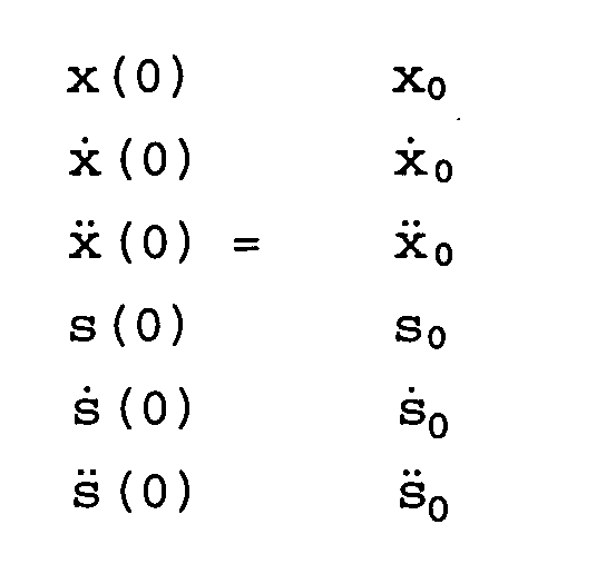
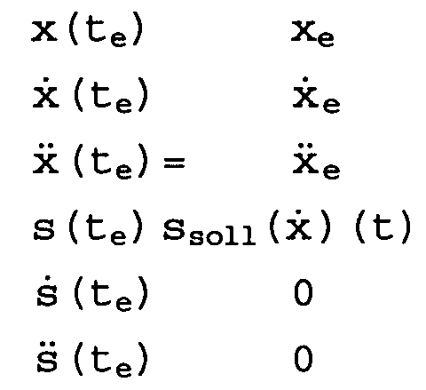


Dies erfolgt, ohne daß der Fahrer aktiv eingreifen muß. Verläßt das Fahrzeug die Kurve und fährt wieder geradeaus, so sinkt die Querbeschleunigung auf Null. Ein Regelungseingriff im Sinne einer Kurvengeschwindigkeitsanpassung ist dann nicht mehr erforderlich.
Fig. 36 der Ablauf einer Ausführungsform des erfindungsgemäßen Verfahrens dargestellt und in
Fig. 37 eine Ausführungsform einer erfindungsgemäßen Steuerung dargestellt.
Claims (113)
- Verfahren zum Steuern bzw. Regeln eines Kraftfahrzeugs, mit den Schritten:Erfassen einer Absolutgeschwindigkeit vabs des Kraftfahrzeugs sowie weiterer Fahrzeugzustandsgrößen, gekennzeichnet durch die Schritte:gleichzeitiges Ermitteln mehrerer Beschleunigungszwischenwerte für das Fahrzeug aus den ermittelten Fahrzeugzustandsgrößen,Ermitteln einer Sollängsbeschleunigung aLsoll nach Maßgabe der ermittelten Beschleunigungszwischenwerte, undRegeln der Fahrzeugaktoren nach Maßgabe der ermittelten Sollängsbeschleunigung.
- Verfahren nach Anspruch 1, dadurch gekennzeichnet, daß die Sollängsbeschleunigung aLsoll derart ermittelt wird, daß aus den Beschleunigungszwischenwerten der kleinste Wert ausgewählt wird.
- Verfahren nach Anspruch 1, dadurch gekennzeichnet, daß die Sollängsbeschleunigung aLsoll derart ermittelt wird, daß aus den Beschleunigungszwischenwerten ein gewichtetes Mittel gebildet wird.
- Verfahren nach Anspruch 3, dadurch gekennzeichnet, daß die Gewichtung der Beschleunigungwerte nach Maßgabe der erfaßten Fahrzeugzustandsgrößen abgeändert wird.
- Verfahren nach Anspruch 3 oder 4, dadurch gekennzeichnet, daß die zeitlichen Änderungen der Gewichtungen durch vorgegebene Zeitfunktionen geglättet werden.
- Verfahren nach einem der Ansprüche 1 bis 5, dadurch gekennzeichnet, daß mindestens ein Beschleunigungszwischenwert nach Maßgabe der Pedalstellungen erzeugt wird.
- Verfahren nach einem der Ansprüche 1 bis 6, dadurch gekennzeichnet, daß ein Beschleunigungszwischenwert nach Maßgabe einer Tempomateinstellung erzeugt wird.
- Verfahren nach einem der vorangehenden Ansprüche, dadurch gekennzeichnet, daß ein Beschleunigungszwischenwert durch eine Fahrzeugfolgeregelung erzeugt wird.
- Verfahren nach einem der vorangehenden Ansprüche, dadurch gekennzeichnet, daß die Funktion von Sensoren und/oder Bescheunigungsreglern durch einen Überwachungsrechner überwacht wird und Warnsignale ausgegeben werden, wenn eine Fehlfunktion festgestellt wird.
- Vorrichtung zum Steuern bzw. Regeln eines Kraftfahrzeugs, mitgekennzeichnet durchEinrichtungen (1-16, 1-17a - c) zum Erfassen der Absolutgeschwindigkeit des Kraftfahrzeugs sowie weiterer Fahrzeugszustandsgrößen,Einrichtungen (1-11a - d) zum gleichzeitigen Ermitteln mehrerer Beschleunigungszwischenwerte (aFolge, aTemp, aPedal),eine Koordinatoreinrichtung (1-12) zum Ermitteln einer Gesamtsollängsbeschleunigung aLsoll aus den Beschleunigungzwischenwerten (aFolge, aTemp, aPedal) undeinen Beschleunigungsregler (1-13), der die Fahrzeugaktoren (1-14a - c) nach Maßgabe der Gesamtsolllängsbeschleunigung (aLsoll) ansteuert.
- Vorrichtung nach Anspruch 10, dadurch gekennzeichnet, daß die Koordinatoreinrichtung (1-12) den kleinsten der ihr eingegebenen Beschleunigungwerte (aFolge, aTemp, aPedal) als Sollängsbeschleunigung (aLsoll) auswählt.
- Vorrichtung nach Anspruch 10, dadurch gekennzeichnet, daß die Koordinatoreinrichtung (1-12) aus den ihr eingegebenen Beschleunigungzwischenwerten (aFolge, aTemp, aPedal) ein gewichtetes Mittel bildet und dieses als Sollängsbeschleunigung (aLsoll) ausgibt.
- Vorrichtung nach Anspruch 12, dadurch gekennzeichnet, daß die Koordinatoreinrichtung (1-12) dazu ausgelegt ist, die Gewichtung der Beschleunigungzwischenwerte (aFolge, aTemp, aPedal) nach Maßgabe der erfaßten Zustandsgrößen zu ändern.
- Vorrichtung nach einem der Ansprüche 10 bis 13, dadurch gekennzeichnet, daß sie eine Einrichtung (1-11c) aufweist, die nach Maßgabe der durch den Fahrer eingestellten Pedalstellungen einen ersten Beschleunigungszwischenwert (aPedal) erzeugt.
- Vorrichtung nach einem der Ansprüche 10 bis 14, dadurch gekennzeichnet, daß sie einen Tempomaten (1-11b) umfaßt, der nach Maßgabe von über Schalter (1-17b) eingegebenen Befehlen einen weiteren Beschleunigungszwischenwert (aTemp) erzeugt.
- Vorrichtung nach Anspruch 14 oder 15, dadurch gekennzeichnet, daß sie einen Fahrzeugfolgeregler (1-11a) aufweist, der nach Maßgabe des Signals eines Abstandssensors (1-17a) einen weiteren Beschleunigungszwischenwert (aFolge) erzeugt.
- Vorrichtung nach einem der vorangehenden Ansprüche, dadurch gekennzeichnet, daß sie einen Speicher für Zeitfunktionen zum Glätten der zeitlichen Änderungen der Gewichtungen aufweist.
- Vorrichtung nach einem der vorangehenden Ansprüche, dadurch gekennzeichnet, daß sie einen Überwachungsrechner aufweist, der ein Fehlverhalten einzelner Sensoren und/oder Beschleunigungsregler erkennt und entsprechende Warnsignale ausgibt.
- Verfahren insbesondere nach Anspruch 1, mit den Schritten:dadurch gekennzeichnet, daß dann, wenn das Abbremsen eines vorausfahrenden Fahrzeugs erkannt wird, ein Beschleunigungszwischenwert für das eigene Fahrzeug ausgegeben wird, daß die Geschwindigkeit des vorausfahrenden Fahrzeugs nicht oder frühestens nach Ablauf einer vorbestimmten Zeitspanne nach Beginn der Verzögerung des vorausfahrenden Fahrzeugs oder nach Einnehmen einer konstanten langsameren Geschwindigkeit des vorausfahrenden Fahrzeugs unterschritten wird.Erfassen des Abstands und der Relativeschwindigkeit von bzw. gegenüber einem vorausfahrenden Fahrzeug, undErzeugen von Sollwertvorgaben für die Regelung des eigenen Fahrzeugs nach Maßgabe des erfaßten Abstands und der Relativgeschwindigkeit,
- Verfahren insbesondere nach Anspruch 1, mit den Schritten:dadurch gekennzeichnet, daß dann, wenn das Abbremsen eines vorausfahrenden Fahrzeugs erkannt wird, ein Beschleunigungezwischenwert ausgegeben wird, so daß die vorgegebenen Abstände über einen vorgegebenen Zeitraum geringer einstellbar sind als die für stationäre Zustände vorgegebenen Abstände, wobei der vorgegebene Zeitraum vom Abstand abhängt.Erfassen des Abstands zu einem vorausfahrenden Fahrzeug, undErzeugen von Sollwertvorgaben für die Regelung des eigenen Fahrzeugs nach Maßgabe des erfaßten Abstandsund der Relativgeschwindigkeit,
- Verfahren nach Anspruch 44, dadurch gekennzeichnet, daß auch für den Zustand stationärer Geschwindigkeit des vorausfahrenden Fahrzeugs nach Beendigung dessen Abbremsvorgangs für das eigene Fahrzeug für eine bestimmte Zeit ein geringerer Abstand zum vorausfahrenden Fahrzeug vorgegeben wird.
- Verfahren nach Anspruch 43, dadurch gekennzeichnet, daß nach Beginn des Abbremsens des vorausfahrenden Fahrzeugs der Abstand zu diesem überwacht wird und im Falle, daß ein bestimmter oder bestimmbarer Mindestabstand unterschritten wird, das eigene Fahrzeug verstärkt abgebremst wird.
- Vorrichtung insbesondere nach Anspruch 10 zur Fahrzeugfolgeregelung mitdadurch gekennzeichnet, daß die Regelung (3-23) umfaßt:einem Abstandssensor (3-21) zur Bestimmung des Abstands und der Relativgeschwindigkeit von bzw. gegenüber einem vorausfahrenden Fahrzeug,einem Geschwindigkeitssensor (3-22) zur Bestimmung der Geschwindigkeit des eigenen Fahrzeugs, undeiner Regelung (3-23) zur Erzeugung und Einstellung von Sollwerten für die Fahrzeugregelung nach Maßgabe der von den Sensoren (3-21, 3-22) gelieferten Werte,eine Einrichtung zum Erkennen des Abbremsens eines vorausfahrenden Fahrzeugs, undeine Einrichtung zum Vorgeben der Beschleunigungszwischenwerte des eigenen Fahrzeugs derart, daß die Geschwindigkeit des vorausfahrenden Fahrzeugs nicht oder frühestens nach Ablauf einer vorbestimmten Zeit nach Beginn der Verzögerung des vorausfahrenden Fahrzeugs oder nach Einnehmen einer konstanten langsameren Geschwindigkeit des vorausfahrenden Fahrzeugs unterschritten wird.
- Vorrichtung zur Fahrzeugfolgeregelung insbesondere nach Anspruch 10, mitdadurch gekennzeichnet, daß die Regelung (3-23) umfaßt:einem Abstandssensor (3-21) zur Bestimmung des Abstands und der Relativgeschwindigkeit von bzw. gegenüber einem vorausfahrenden Fahrzeug,einem Geschwindigkeitssensor (3-22) zur Bestimmung der Geschwindigkeit des eigenen Fahrzeugs, undeiner Regelung (3-23) zur Erzeugung und Einstellung von Sollwerten für die Fahrzeugregelung nach Maßgabe der von den Sensoren (3-21, 3-22) gelieferten Werte,eine Einrichtung zum Erkennen des Abbremsens eines vorausfahrenden Fahrzeugs, undeine Einrichtung zum Erzeugen von Abstandsvorgaben zwischen vorausfahrendem Fahrzeug und eigenem Fahrzeug derart, daß die vorgegebenen Abstände über einen vorgegebenen Zeitraum geringer einstellbar sind als die für stationäre Zustände vorgegebenen Abstände, wobei der vorgegebene Zeitraum vom Abstand abhängt.
- Vorrichtung nach Anspruch 48, dadurch gekennzeichnet, daß die Einrichtung zur Erzeugung von Abstandsvorgaben auch für den Zustand stationärer Geschwindigkeit des vorausfahrenden Fahrzeugs nach Beendigung dessen Abbremsvorgangs für eine bestimmte Zeit einen geringeren Abstand vorgibt.
- Vorrichtung nach Anspruch 47, dadurch gekennzeichnet, daß die Regelung (3-23) eine Einrichtung zum Überwachen des Abstands zum vorausfahrenden Fahrzeug aufweist, die im Falle, daß ein bestimmter oder bestimmbarer Mindestabstand unterschritten wird, Steuersignale zum verstärkten Abbremsen des eigenen Fahrzeugs ausgibt.
- Verfahren insbesondere nach Anspruch 1 zum Erzeugen eines eine Fahrzeuggeschwindigkeit angebenden Geschwindigkeitssignals, mit dem Schritt des Erzeugens eines Roh-Geschwindigkeitssignals VE, gekennzeichnet durch eine Tiefpaßfilterung des Roh-Geschwindigkeitssignals vE.
- Verfahren zum Erzeugen eines eine Fahrzeuggeschwindigkeit angebenden Geschwindigkeitssignals, insbesondere nach Anspruch 51, mit dem Schritt des Erzeugens eines Roh-Geschwindigkeitssignals vE, gekennzeichnet durch eine Bandsperrenfilterung des tiefpaßgefilterten Roh-Geschwindigkeitssignals vE bzw. ein Tiefpaßfiltern des bandsperrengefilterten Roh-Geschwindigkeitssignals vE.
- Verfahren nach Anspruch 51, gekennzeichnet durch Filterung mit einem Tiefpaß erster Ordnung.
- Verfahren nach Anspruch 53, dadurch gekennzeichnet, daß im Tiefpaß eine Gradientenbeschränkung vorgesehen ist.
- Verfahren nach einem der Ansprüche 51 bis 54, dadurch gekennzeichnet, daß die Filterkennlinie der Tiefpaßfilterung nach Maßgabe der Fahrzeugbeschleunigung oder einem entsprechenden Signal modifiziert wird.
- Verfahren nach Anspruch 52, bei dem die bandbegrenzte Störfrequenz nachgebildet und vom nichtbandgefilterten Signal subtrahiert wird.
- Verfahren nach Anspruch 56, dadurch gekennzeichnet, daß das nach der Subtraktion gewonnene Signal in die Nachbildung des Störfrequenzbands zurückgeführt wird.
- Verfahren nach Anspruch 52 oder 56 oder 57, dadurch gekennzeichnet, daß die Bandsperre einen Frequenzbereich von ca. 1 bis 4 Hz abdeckt.
- Verfahren nach Anspruch 51 oder 53 bis 55, dadurch gekennzeichnet, daß der Tiefpaß Frequenzen von 8 Hz und höher herausfiltert.
- Vorrichtung insbesondere nach Anspruch 10 zum Erzeugen eines eine Fahrzeuggeschwindigkeit angebenden Geschwindigkeitssignals, mit einer Einrichtung zum Erzeugen eines Roh-Geschwindigkeitssignals vE, gekennzeichnet durch einen Tiefpaßfilter (4-20, 4-30 - 4-34) zur Filterung des Roh-Geschwindigkeitssignals vE.
- Vorrichtung zum Erzeugen eines eine Fahrzeuggeschwindigkeit angebenden Geschwindigkeitssignals, insbesondere nach Anspruch 60, mit einer Einrichtung zum Erzeugen eines Roh-Geschwindigkeitssignals vE, gekennzeichnet durch einen Bandsperrenfilter (4-21, 4-40 - 4-46) zur Filterung des Roh-Geschwindigkeitssignals vE oder des tiefpaßgefilterten Roh-Geschwindigkeitssignals vE.
- Vorrichtung nach Anspruch 60, gekennzeichnet durch einen Tiefpaßfilter erster Ordnung.
- Vorrichtung nach Anspruch 62, dadurch gekennzeichnet, daß im Tiefpaß eine Gradientenbeschränkung (4-32) vorgesehen ist.
- Vorrichtung nach einem der Ansprüche 60 bis 63, gekennzeichnet durch eine Einrichtung (4-33), mit der die Filterkennlinie der Tiefpaßfilterung nach Maßgabe der Fahrzeugbeschleunigung oder einem entsprechenden Signal modifiziert wird.
- Vorrichtung nach Anspruch 61, gekennzeichnet durch eine Einrichtung (4-43 - 4-46) zum Nachbilden des durch den Bandsperrenfilter (4-21, 4-40 - 4-46) herauszufilternden Störfrequenzbands, und eine Einrichtung (4-40) zum Subtrahieren des nachgebildeten Signals vom Eingangssignal.
- Vorrichtung nach Anspruch 65, gekennzeichnet durch Einrichtungen (4-41, 4-42) zum Rückführen des Ausgangssignals in die Einrichtung (4-43 - 4-46) zur Nachbildung des Störfrequenzbands.
- Vorrichtung nach Anspruch 61 oder 65 oder 66, dadurch gekennzeichnet, daß der Bandsperrenfilter (4-21, 4-40 - 4-46) einen Frequenzbereich von ca. 1 bis 4 Hz abdeckt.
- Vorrichtung nach Anspruch 60 oder 62 bis 64, dadurch gekennzeichnet, daß der Tiefpaßfilter (4-20, 4-30 - 4-34) Frequenzen von 8 Hz und höher herausfiltert.
- Verfahren für die Fahrzeugregelung insbesondere nach Anspruch 1, gekennzeichnet durch einen Schritt des Tiefpaßfilterns des Sollgeschwindigkeitssignals VSoll.
- Verfahren für die Fahrzeugregelung, insbesondere nach Anspruch 69, mit einem Schritt des Bestimmens eines Sollgeschwindigkeitssignals VSoll, gekennzeichnet durch einen Schritt der Gradientenbegrenzung des Sollgeschwindigkeitssignals VSoll.
- Verfahren für die Fahrzeugregelung, insbesondere nach Anspruch 69 oder 70, mit einem Schritt des Bestimmens eines Sollgeschwindigkeitssignals Vsoll, gekennzeichnet durch einen Schritt des Bildens der Differenz Δv zwischen Sollgeschwindigkeitssignals vsoll und tatsächlicher Geschwindigkeit vRef, und einen Schritt des Ermittelns eines Beschleunigungszwischenwertes azwi nach Maßgabe der Differenz Δv.
- Verfahren für die Fahrzeugregelung, insbesondere nach einem der Ansprüche 69 bis 71, mit einem Schritt des Bestimmens eines Sollgeschwindigkeitssignals vsoll, gekennzeichnet durch einen Schritt des Ermittelns eines Beschleunigungszwischenwertes azwi und einen Schritt des Addierens von asoll und eines nach Maßgabe des Sollgeschwindigkeitssignals vsoll ermittelten Feed-Forward-Anteils.
- Verfahren nach einem der Ansprüche 69 bis 72, dadurch gekennzeichnet, daß die Fahreraktivitäten wie Beschleunigungsdauer, Beschleunigungsgröße und Beschleunigungshäufigkeit beobachtet werden und lernend zur Modifizierung von Tiefpaßcharakreristika, Gradientenbegrenzung, Sollbeschleunigungskennlinie oder Feed-Forward-Kennlinie verwendet werden.
- Verfahren nach Anspruch 69, dadurch gekennzeichnet, daß eine Tiefpaßfilterung erster Ordnung vorgenommen wird, die aus einer Verstärkung, einer Integration und einer gegenkoppelnden Rückführung besteht.
- Verfahren nach Anspruch 74, dadurch gekennzeichnet, daß zum Zwecke der Gradientenbegrenzung die Verstärkung begrenzt ist.
- Verfahren nach Anspruch 71, dadurch gekennzeichnet, daß der Beschleunigungszwischenwert nach Maßgabe der Differenz zwischen tiefpaßgefilterter Sollgeschwindigkeitsvorgabe und Istgeschwindigkeit des Fahrzeugs ermittelt wird.
- Verfahren nach Anspruch 72, 74 und 76, dadurch gekennzeichnet, daß der Feed-Forward-Anteil nach Maßgabe des im Tiefpaß vorliegenden verstärkten Signals ermittelt und zum Beschleunigungszwischenwert addiert wird.
- Verfahren nach Anspruch 71 oder 76, dadurch gekennzeichnet, daß der Beschleunigungszwischenwert auf vorgegebene Werte begrenzt wird, wobei die Begrenzungen situativ veränderbar sein können.
- Vorrichtung für die Fahrzeugregelung insbesondere nach Anspruch 10, mit einer Einrichtung zur Ermittlung eines Sollgeschwindigkeitssignals VSoll, gekennzeichnet durch einen Tiefpaßfilter (5-10, 5-11, 5-12) für das Sollgeschwindigkeitssignal vSoll.
- Vorrichtung für die Fahrzeugregelung, insbesondere nach Anspruch 79, mit einer Einrichtung zur Ermittlung eines Sollgeschwindigkeitssignals VSoll, gekennzeichnet durch eine Einrichtung (5-11) zur Begrenzung des Gradienten des Sollgeschwindigkeitssignals vSoll.
- Vorrichtung für die Fahrzeugregelung, insbesondere nach Anspruch 79 oder 80, mit einer Einrichtung zur Ermittlung eines Sollgeschwindigkeitssignals VSoll, gekennzeichnet durch eine Vorrichtung (5-13) zum Bilden der Differenz Δv zwischen Sollgeschwindigkeitssignal vSoll und tatsächlicher Geschwindigkeit vRef, und einer Einrichtung (5-15) zum Ermitteln eines Beschleunigungszwischenwertes nach Maßgabe der Differenz Δv.
- Vorrichtung für die Fahrzeugregelung, insbesondere nach einem der Ansprüche 79 bis 81, mit einer Einrichtung zur Ermittlung eines Sollgeschwindigkeitssignals Vsoll, gekennzeichnet durch eine Einrichtung (5-15) zur Ermittlung eines Beschleunigungszwischenwertes, eine Einrichtung (5-18) zum Ermitteln eines Feed-Forward-Anteils in Abhängigkeit vom Sollgeschwindigkeitssignal vSoll, und eine Einrichtung (5-16) zum Addieren von Beschleunigungszwischenwert und Feed-Forward-Anteil.
- Vorrichtung nach einem der Ansprüche 79 bis 82, gekennzeichnet durch eine Einrichtung, die die Fahreraktivitäten wie Beschleunigungsdauer, Beschleunigungsgröße und Beschleunigungshäufigkeit beobachtet und lernend zur Modifizierung von Tiefpaßcharakteristika, Gradientenbegrenzung, Sollbeschleunigungskennlinie oder Feed-Forward-Kennlinie verwendet.
- Vorrichtung nach Anspruch 79, gekennzeichnet durch einen Tiefpaß erster Ordnung (5-10 - 5-12), der aus einer Verstärkung (5-11), einer Integration (5-12) und einer gegenkoppelnden Rückführung (5-10) besteht.
- Vorrichtung nach Anspruch 84, dadurch gekennzeichnet, daß zum Zwecke der Gradientenbegrenzung die Verstärkung (5-11) begrenzt ist.
- Vorrichtung nach Anspruch 81, dadurch gekennzeichnet, daß der Beschleunigungszwischenwert nach Maßgabe der Differenz zwischen tiefpaßgefilterter Sollgeschwindigkeitsvorgabe und Istgeschwindigkeit des Fahrzeugs ermittelt wird.
- Vorrichtung nach Anspruch 82, 84 und 86, dadurch gekennzeichnet, daß die Einrichtung (5-18) zur Erzeugung des Feed-Forward-Anteils das Signal am Ausgang der Verstärkung (5-11) abgreift, und daß der Feed-Forward-Anteil zum Ausgangssignal der Einrichtung (5-15) addiert wird.
- Vorrichtung nach Anspruch 81, gekennzeichnet durch eine Einrichtung (5-17) zur Begrenzung des Beschleunigungszwischenwertes, wobei die Grenzwerte der Einrichtung (5-17) veränderbar sein können.
- Verfahren insbesondere nach Anspruch 1 zum Erzeugen eines Bremssolldrucks Psoll mit den Schritten:gekennzeichnet durch Ausgeben eines Druckaufbausignals und eines Druckabbausignals an Mittel (6-7, 6-8) zum Einstellen des Bremssolldrucks Psoll.Erfassen eines Bremsmessdrucks pmess,
- Verfahren nach Anspruch 89, gekennzeichnet durch Bestimmen eines Sollvolumenstroms Qsoll aus dem Bremssolldruck Psoll und einem einem Meßdruck pmess entsprechenden Istdruck pist an mindestens einem Bremszylinder.
- Verfahren nach Anspruch 90, gekennzeichnet durch Bestimmen des Istdrucks pist aus einer hydraulischen Impedanz Dv und dem Meßdruck pmess.
- Verfahren nach Anspruch 90 oder 91, gekennzeichnet durch Bestimmen des Druckaufbausignals und des Druckabbausignals aus dem Sollvolumenstrom Qsoll und einem dem Meßdruck pmess entsprechenden Istvolumenstrom Qist.
- Verfahren nach Anspruch 92, gekennzeichnet durch Bestimmen des Druckaufbausignals und des Druckabbausignals aus dem Sollvolumenstrom Qsoll, einem dem Meßdruck pmess entsprechenden Istvolumenstrom Qist und der zeitlichen Ableitung des Istvolumenstroms Qist.
- Verfahren nach einem der Ansprüch 90 bis 93, gekennzeichnet durch Bestimmen des Istvolumenstroms Qist aus der hydraulischen Impedanz Dv und einer Differenz u zwischen dem Meßdruck pmess und dem Istdruck pist.
- Verfahren nach einem der Ansprüche 89 bis 94, dadurch gekennzeichnet, daß das Druckaufbausignal und das Druckabbausignal zueinander komplementär sind.
- Steuerungsvorrichtung insbesondere nach Anspruch 10 zum Erzeugen eines Bremssolldrucks psoll, die eine Vorrichtung zum Erfassen eines Bremssolldrucks und Mittel (6-7, 6-8) zum Einstellen des Bremsdrucks umfaßt, gekennzeichnet durch eine Ausgabevorrichtung zum Ausgeben eines Druckaufbausignals und eines Druckabbausignals an die Mittel zum Einstellen des Bremsdrucks, wobei das Druckaufbausignal und das Druckabbausignal so gewählt sind, daß ein Bremssolldruck Psoll erreicht wird.
- Steuerungsvorrichtung nach Anspruch 96, gekennzeichnet durch eine Druckregelungsvorrichtung mit einem Druckregler (6-2) und einem Druckbeobachter (6-3) zum Bestimmen eines Sollvolumenstroms Qsoll aus dem Bremssolldruck Psoll und einem einem Meßdruck pmess entsprechenden Istdruck pist an einem Bremszylinder.
- Steuerungsvorrichtung nach Anspruch 97, dadurch gekennzeichnet, daß der Druckbeobachter (6-3) und/oder Volumenstrombeobachter (6-5) ein Multiplikatorglied (6-10), einen Integrator (6-11) und ein Kennlinienglied (6-12) umfaßt.
- Steuerungsvorrichtung nach Anspruch 97, dadurch gekennzeichnet, daß der Druckbeobachter (6-3) und/oder Volumenstrombeobachter (6-5) ein erstes Proportionalglied (6-17), einen Integrator (6-11) und ein zweites Proportionalglied (6-18) umfaßt.
- Steuerungsvorrichtung nach einem der Ansprüche 97 bis 99, gekennzeichnet durch einen Volumenstromregler (6-4) zum Umsetzen der Druckaufbau- und Druckabbausignale in Steuersignale (s) für die Mittel (6-7, 6-8) und einen Volumenstrombeobachter (6-5) zum Ermitteln eines dem Meßdruck pmess entsprechenden Istvolumenstroms Qist, der dem Sollvolumenstrom Qsoll gegengekoppelt wird, zwischen der Druckregelungsvorrichtung und der Hydraulik (6-6).
- Steuervorrichtung nach Anspruch 100, dadurch gekennzeichnet, daß der Volumenstrombeobachter (6-5) ein DT1-Glied ist und der Volumenstromregler (6-4) ein drittes Subtrahierglied (6-19) zum Abzug des Ausgangssignals des Volumenstrombeobachters (6-5) von dem Ausgangssignal der Druckregelung, ein viertes Subtrahierglied (6-20) zum Abzug des Ausgangssignals des Volumenstrombeobachters (6-5) von dem Ausgangssignal der Druckregelung zum Erzeugen eines Zwischensignals (s) und ein zweites und ein drittes Kennlinienglied (6-23, 6-24) zum Erzeugen eines Steuersignals für die Mittel (6-7, 6-8) zum Einstellen des Bremsdrucks umfaßt.
- Steuervorrichtung nach Anspruch 101, dadurch gekennzeichnet, daß der Volumenstromregler (6-4) ein erstes und ein zweites DT1-Glied (6-21, 6-22) umfaßt, an deren Eingang jeweils das Ausgangssignal von dem Volumenstrombeobachter (6-5) anliegt und deren Ausgang jeweils von dem Ausgang des dritten bzw. vierten Subtrahierer (6-19, 6-20) abgezogen wird.
- Steuerungsvorrichtung nach einem der Ansprüche 96 bis 102, dadurch gekennzeichnet, daß die Mittel (6-7, 6-8) zum Einstellen des Bremsdrucks ein stromlos geschlossenes Ventil (6-7) oder einen Druckerzeuger (6-25) umfassen.
- Steuervorrichtung nach einem der Ansprüche 96 bis 103 dadurch gekennzeichnet, daß die Mittel (6-7, 6-8) zum Einstellen des Bremsdrucks ein stromlos offenes Ventil (6-8) und/oder einen Druckerzeuger (6-25) umfassen.
- Verfahren insbesondere nach Anspruch 1 zum ruckarmen Überführen der Fahrzeuglängsbewegung aus einem ersten Fahrzustand in einen zweiten Fahrzustand mit den Schritten:Erfassen eines erstenFahrzeugzustandes gekennzeichnet durch Ausgeben einer Sollängsbschleunigung aLsoll zum Erreichen eines Sollzustandes mit einem Sollabstand, einer Sollrelativgeschwindigkeit und einer Sollrelativbeschleunigung aus einem Istzustand mit einem Abstand, einer Absolutgeschwindigkeit und einer Absolutbeschleunigung in einem vorgegebenen Zeitintervall te als eine zeitabhängige Beschleunigungsfunktion, deren Integral über das Quadrat ihrer zeitlichen Ableitung unter der Randbedigung, daß Anfangs- und Endzustand definiert sind, minimal ist.
- Verfahren nach Anspruch 105, dadurch gekennzeichnet, daß die Beschleunigungsfunktion unter mehreren Funktionen ausgewählt wird, die vorab in einem Speicher abgespeichert wurden.
- Verfahren nach Anspruch 106, dadurch gekennzeichnet, daß die abgespeicherten Funktionen mindestens eine quadratisch von der Zeit abhängige Funktion umfassen.
- Verfahren nach einem der Ansprüche 106 bis 107, dadurch gekennzeichnet, daß die abgespeicherten Funktionen mindestens eine kubisch von der Zeit abhängige Funktion umfassen.
- Verfahren nach Anspruch 106, dadurch gekennzeichnet, daß die abgespeicherten Funktionen mindestens eine exponentiell von der Zeit abhängige Funktion umfassen.
- Verfahren nach einem der Ansprüche 106 bis 109, dadurch gekennzeichnet, daß die abgespeicherten Beschleunigungsfunktionen parametrisch von der vorgegebenen Übergangszeit te zum Erreichen des Sollzustandes und/oder vom Sollabstand Asoll und/oder von der momentanen Absolutgeschwindigkeit und/oder der momentanen Beschleunigung und/oder der momentanen Relativgeschwindigkeit und/oder der momentanen Relativbeschleunigung abhängen.
- Verfahren nach einem der Ansprüche 105 bis 110, dadurch gekennzeichnet, daß das vorgegebene Zeitintervall te eine von Sollgeschwindigkeit und/oder Sollabstand und/oder Absolutgeschwindigkeit und/oder Abstand abhängige Funktion ist.
- Steuerungsvorrichtung insbesondere nach Anspruch 10 zum Überführen einer Fahrzeuglängsbewegung von einem ersten Fahrzustand in einen zweiten Fahrzustand mit:einer Recheneinheit,Fahrzustandssensoren für das Erfassen von vorgegebenen Größen eines ersten Fahrzustandes als Eingangsgrößen für die Recheneinheit,Stellgliedern zum Umsetzen von Ausgangsgrößen der Recheneinheit in Steuersignale zum Erreichen eines zweiten Fahrzustands, gekennzeichnet durcheinen ersten Speicher zum Abspeichern eines numerischen Wertes,mehrere Funktionsspeicher zum Abspeichern von jeweils wenigstens einem Funktionsparameter,einen Funktionsspeicher zum Abspeichern von mehreren Funktionsparametern,einen Differenzierglied zum Differenzieren einer Funktion, einen Quadrierglied zum Quadrieren der differenzierten Funktion,einen Integrator zum Integrieren der differenzierten und quadrierten Funktion undeinen Vergleicher zum Vergleichen eines Ausgangswertes des Integrators mit dem numerischen Wert in dem Speicher und zum Ausgeben einer Funktion.
- Steuerungsvorrichtung nach Anspruch 112, dadurch gekennzeichnet, daß die mehreren Funktionsspeicher zum Abspeichern von jeweils wenigstens einem Funktionsparameter umfassen:mehrere Funktionsspeicher zum Abspeichern von jeweils einem Funktionsparameter undein Multiplikatorglied zum Multiplizieren von mehreren Funktionen miteinander.
- Verfahren insbesondere nach Anspruch 1, das umfaßt:gekennzeichnet durch Ausgeben einer Sollfolgebeschleunigung (aFsoll) zum Erreichen des Sollabstandes (Asoll) zu einem vorausfahrenden Fahrzeug, die von dem Abstand (s), der Relativgeschwindigkeit (vrel) und der Absolutgeschwindigkeit (vabs) abhängig ist.Erfassen eines Abstandes (s) zu einem vorausfahrenden Fahrzeug (8-2),Erfassen einer Relativgeschwindigkeit (vrel) gegenüber dem vorausfahrenden Fahrzeug (8-2),Ermitteln eines Sollabstandes Asoll zu dem vorausfahrenden Fahrzeug (8-2),
- Verfahren nach Anspruch 114, gekennzeichnet durch Ermitteln der Sollfolgebeschleunigung (aFsoll) aus einer ersten Komponente, die linear von dem Abstand (s) abhängt, einer zweiten Komponente, die quasi-linear von der Relativgeschwindigkeit (vrel) abhängt, und einer dritten Komponente, die linear von der Absolutgeschwindigkeit (vabs) abhängt, wobei mindestens zwei der drei Proportionalitätsfaktoren nicht-linear von der Relativgeschwindigkeit (vrel) abhängen.
- Verfahren nach Anspruch 115, dadurch gekennzeichnet, daß die zweite Komponente der Sollfolgebeschleunigung (aFsoll) bei kleinen Relativgeschwindigkeiten (vrel) und/oder Absolutgeschwindigkeiten (Vabs) größer als die dritte Komponente der Sollfolgebeschleunigung (aFsoll) und bei großen Relativgeschwindigkeiten (vrel) und/oder Absolutgeschwindigkeiten (vabs) kleiner als die dritte Komponente der Sollfolgebschleunigung (aFsoll) ist.
- Verfahren nach einem der Ansprüche 114 bis 115, dadurch gekennzeichnet, daß die Sollfolgebeschleunigung (aFsoll) einen vorgegebenen Grenzwert nicht überschreitet.
- Steuerungsvorrichtung insbesondere nach Anspruch 10 mit:gekennzeichnet durch eine Recheneinheit (8-7 - 8-10) zur Ausgabe einer Sollfolgebeschleunigung (aFsoll), die von dem Abstand (s) , der Relativgeschwindigkeit (vrel) und der Absolutgeschwindigkeit (vabs) abhängig ist.Abstandssensor (8-5) zum Erfassen eines Abstandes (s) zu einem vorausfahrenden Fahrzeuges (8-2),
- Steuerungsvorrichtung nach Anspruch 118, dadurch gekennzeichnet, daß die Recheneinheit ein Dämpfungskennlinienglied (8-8) zur Ausgabe einer ersten Komponente, die von dem Abstand (s) abhängt, und ein Federkennlinienglied (8-9) zur Ausgabe einer zweiten Komponente, die von der Relativgeschwindigkeit (vrel) abhängt, wobei beide Komponenten außerdem von der Absolutgeschwindigkeit (vabs) abhängen, sowie einen Addierer (8-10) zum Addieren der ersten und der zweiten Komponente und Ausgabe eines Beschleunigungswertes umfaßt.
- Steuerungsvorrichtung nach Anspruch 118, dadurch gekennzeichnet, daß die Recheneinheit ein Kennfeldglied (8-12) zur Ausgabe eines Beschleunigungswertes, der von dem Abstand (s) und von der Relativgeschwindigkeit (vrel) abhängt, umfaßt, wobei der Beschleunigungswert außerdem von der Absolutgeschwindigkeit (vabs) abhängt.
- Steuerungsvervorrichtung nach einem der Ansprüche 118 bis 120, gekennzeichnet durch ein Filter (8-11) zum Glätten und zum Begrenzen des Beschleunigungswertes.
- Verfahren insbesondere nach Anspruch 1 mit den Schritten:gekennzeichnet durch Ausgeben (9-S7, 9-S8) eines zweiten Sollabstandes (Asoll') bei Betätigen des Fahrpedals, Einstellen (9-S8) des zweiten Sollabstands (Asoll').Erfassen (9-S2) eines momentanen Abstandes (s) zu dem vorausfahrenden Fahrzeug,Erfassen (9-S3) einer Absolutgeschwindigkeit (vabs), Bestimmen (9-S4) des Sollabstandes (Asoll) aus der Absolutgeschwindigkeit (vabs),Einstellen (9-S6) des Sollabstands (Asoll),
- Verfahren nach Anspruch 122, dadurch gekennzeichnet, daß der zweite Sollabstand (Asoll) gegenüber dem ersten Sollabstand entsprechend der Stellung des Fahrpedals (ϕ) verkürzt ist.
- Verfahren nach Anspruch 123, dadurch gekennzeichnet, daß die Verkürzung des ersten zum zweiten Sollabstand (Asoll) nicht-linear von der Stellung (ϕ) des Fahrpedals abhängt.
- Verfahren nach Anspruch 123, dadurch gekennzeichnet, daß je nach Größe des zweiten Sollabstands ein optisches und/oder akustisches und/oder haptisches Warnsignal ausgegeben wird.
- Steuerungsvorrichtung insbesondere nach Anspruch 10 mit
einem Abstandssensor zum Erfassen eines Abstandes (s) zu dem vorausfahrenden Fahrzeug,
einer Rechnereinheit zum Bestimmen des Sollabstandes (Asoll) aus der Absolutgeschwindigkeit (vabs), gekennzeichnet durch
eine Steuereinrichtung zum Einstellen eines Sollabstands (Asoll),
eine Vorrichtung zum Ausgeben eines zweiten Sollabstandes (Asoll') bei Betätigen des Fahrpedals an die Steuereinrichtung. - Verfahren zum Steuern bzw. Regeln eines Fahrzeugs insbesondere nach Anspruch 1, gekennzeichnet durch Ermitteln (10-S1) einer Querbeschleunigung (aQ) des Fahrzeugs,
Vergleichen (10-S2) der Querbeschleunigung (aQ) mit einer Referenzquerbeschleunigung (aQRef)und Ausgeben (10-S3) eines Geschwindigkeitskorrektursignals als Beschleunigungszwischenwert (azwi). - Verfahren nach Anspruch 127, dadurch gekennzeichnet, daß die Grenzquerbeschleunigung (aQGrenz) zwischen 2 und 3 m/s2 liegt.
- Verfahren nach Anspruch 126 oder 127, dadurch gekennzeichnet, daß das Geschwindigkeitskorrektursignal ein Änderungssignal für eine Tempomatsollgeschwindigkeit ist.
- Verfahren nach einem der Ansprüche 126 bis 128, gekennzeichnet durch Bestimmen der Querbeschleunigung (aQ) aus einer Gierrate und der Absolutgeschwindigkeit (vabs) des Fahrzeugs.
- Verfahren nach Anspruch 130, dadurch gekennzeichnet, daß die Gierrate aus mehreren Raddrehzahlen bestimmt wird.
- Verfahren nach Anspruch 130, dadurch gekennzeichnet, daß die Gierrate aus einem Ausgangssignal von einem Lenkradstellungssensor sowie der Absolutgeschwindigkeit bestimmt wird.
- Verfahren nach Anspruch 130, dadurch gekennzeichnet, daß die Gierrate aus einem Ausgangssignal von einem Gierratensensor bestimmt wird.
- Steuerungsvorrichtung insbesondere nach Anspruch 10 zur Durchführung des Verfahrens nach Anspruch 127, gekennzeichnet durch
Mittel (10-2) zum Erfassen einer Querbeschleunigung (aQ) des Fahrzeugs,
eine Vergleichsvorrichtung (10-3) zum Vergleichen der Querbeschleunigung mit einer Referenzquerbeschleunigung und
eine Ausgabevorrichtung (10-4) zum Ausgeben eines Geschwindigkeitskorrektursignals als Beschleunigungszwischenwert (azwi). - Steuerungsvorrichtung nach Anspruch 134, dadurch gekennzeichnet, daß die Mittel (10-2) zum Erfassen der Querbeschleunigung einen Gierratensensor zum Erfassen der Gierrate des Fahrzeugs umfassen.
- Steuerungsvorrichtung nach Anspruch 134, dadurch gekennzeichnet, daß die Mittel (10-2) zum Erfassen einer Querbeschleunigung den Rädern des zugeordnete Drehzahlsensoren umfassen.
- Steuerungsvorrichtung nach Anspruch 134 dadurch gekennzeichnet, daß die Mittel (10-2) zum Erfassen der Querbeschleunigung einen Lenkradstellungssensor umfassen.
Applications Claiming Priority (3)
| Application Number | Priority Date | Filing Date | Title |
|---|---|---|---|
| DE19654769A DE19654769A1 (de) | 1996-12-30 | 1996-12-30 | Verfahren und Vorrichtung zur Fahrzeugsteuerung bzw. -regelung |
| DE19654769 | 1996-12-30 | ||
| EP97954454A EP0946377B1 (de) | 1996-12-30 | 1997-12-22 | Verfahren und vorrichtung zur fahrzeugsteuerung bzw. -regelung |
Related Parent Applications (1)
| Application Number | Title | Priority Date | Filing Date |
|---|---|---|---|
| EP97954454A Division EP0946377B1 (de) | 1996-12-30 | 1997-12-22 | Verfahren und vorrichtung zur fahrzeugsteuerung bzw. -regelung |
Publications (1)
| Publication Number | Publication Date |
|---|---|
| EP1285808A1 true EP1285808A1 (de) | 2003-02-26 |
Family
ID=7816430
Family Applications (2)
| Application Number | Title | Priority Date | Filing Date |
|---|---|---|---|
| EP97954454A Expired - Lifetime EP0946377B1 (de) | 1996-12-30 | 1997-12-22 | Verfahren und vorrichtung zur fahrzeugsteuerung bzw. -regelung |
| EP02020597A Ceased EP1285808A1 (de) | 1996-12-30 | 1997-12-22 | Verfahren und Vorrichtung zur Fahrzeugsteuerung bzw.-regelung |
Family Applications Before (1)
| Application Number | Title | Priority Date | Filing Date |
|---|---|---|---|
| EP97954454A Expired - Lifetime EP0946377B1 (de) | 1996-12-30 | 1997-12-22 | Verfahren und vorrichtung zur fahrzeugsteuerung bzw. -regelung |
Country Status (4)
| Country | Link |
|---|---|
| EP (2) | EP0946377B1 (de) |
| KR (1) | KR20000062431A (de) |
| DE (2) | DE19654769A1 (de) |
| WO (1) | WO1998029279A2 (de) |
Cited By (3)
| Publication number | Priority date | Publication date | Assignee | Title |
|---|---|---|---|---|
| WO2009122262A1 (en) | 2008-04-01 | 2009-10-08 | Toyota Jidosha Kabushiki Kaisha | Following distance control device and following distance control method |
| DE102004013655B4 (de) * | 2003-04-03 | 2013-08-14 | Honda Motor Co., Ltd. | Fahrtregelvorrichtung für ein Fahrzeug |
| DE102009008302B4 (de) | 2008-06-11 | 2022-10-06 | Volkswagen Ag | Verfahren und Vorrichtung zur integrierten Quer- und Längsführung eines Kraftfahrzeugs |
Families Citing this family (67)
| Publication number | Priority date | Publication date | Assignee | Title |
|---|---|---|---|---|
| DE19704890B4 (de) * | 1997-02-10 | 2010-07-22 | Continental Teves Ag & Co. Ohg | Verfahren und Vorrichtung zum Ermitteln der Relativgeschwindigkeit eines Fahrzeugs |
| DE19704854A1 (de) | 1997-02-10 | 1998-08-13 | Itt Mfg Enterprises Inc | Verfahren und Vorrichtung zur Regelung der Längsdynamik eines Fahrzeugs |
| DE19719476A1 (de) * | 1997-05-07 | 1998-11-12 | Man Nutzfahrzeuge Ag | Bedienhebel und Bedienmanagement für einen abstandsgeregelten Fahrgeschwindigkeitsregler |
| DE19806119A1 (de) * | 1998-02-14 | 1999-08-19 | Bayerische Motoren Werke Ag | Bremsregelungsanlage in Kraftfahrzeugen |
| DE19806687A1 (de) * | 1998-02-18 | 1999-08-26 | Daimler Chrysler Ag | Verfahren zur Verhinderung einer Kollision eines Fahrzeugs mit einem vor dem Fahrzeug angeordneten Hindernis und Bremsvorrichtung |
| DE19936586B4 (de) * | 1998-08-04 | 2015-04-09 | Denso Corporation | Vorrichtung und Verfahren zum Steuern eines Soll-Abstands und eines Warnabstands zwischen zwei sich bewegenden Fahrzeugen und Datenträger zum Speichern des Steuerverfahrens |
| JP3661495B2 (ja) | 1998-08-26 | 2005-06-15 | 日産自動車株式会社 | 先行車追従制御装置 |
| GB9818960D0 (en) * | 1998-09-02 | 1998-10-21 | Rover Group | A vehicle |
| JP2000108860A (ja) * | 1998-10-06 | 2000-04-18 | Toyota Motor Corp | ブレーキ制御装置 |
| WO2000061412A1 (de) * | 1999-04-12 | 2000-10-19 | Continental Teves Ag & Co. Ohg | Verfahren zur fahrzeugsteuerung |
| DE10021436B4 (de) * | 1999-05-04 | 2009-12-10 | Continental Teves Ag & Co. Ohg | Verfahren und Einrichtung zum Ermitteln einer Stellgröße eines Ventils und Verfahren und Einrichtung zum Ermitteln einer die Bewegungsgeschwindigkeit eines Aktuators eines Ventils wiedergebenden Größe |
| DE19937475A1 (de) * | 1999-08-07 | 2001-02-08 | Continental Teves Ag & Co Ohg | Vorrichtung und Verfahren zum Steuern einer hydraulischen Bremsanlage |
| DE19937818A1 (de) * | 1999-08-11 | 2001-02-15 | Continental Teves Ag & Co Ohg | Verfahren und Vorrichtung zum Steuern einer Fahrzeugbremsanlage |
| DE19947313B4 (de) * | 1999-10-01 | 2016-10-27 | Volkswagen Ag | Vorrichtung zur Begrenzung der Geschwindigkeit eines Fahrzeuges, insbesondere eines Landfahrzeuges |
| DE10021135B4 (de) * | 2000-04-29 | 2007-08-30 | Bayerische Motoren Werke Ag | Verfahren und Vorrichtung zur Regelung einer vorgegebenen Soll-Verzögerung eines Kraftfahrzeugs |
| DE10031849B4 (de) * | 2000-07-04 | 2014-05-15 | Robert Bosch Gmbh | Vorrichtung und Verfahren zur Stabilisierung eines Fahrzeuges |
| US6634722B1 (en) | 2001-07-31 | 2003-10-21 | Kelsey-Hayes Company | Vehicle braking system with proportional poppet valve pressure control strategy |
| US8121770B2 (en) | 2001-07-31 | 2012-02-21 | Kelsey-Hayes Company | Boundary adaptation scheme for spool valve pressure control |
| JP4489333B2 (ja) * | 2001-09-26 | 2010-06-23 | 日産自動車株式会社 | 車両の駆動力制御装置 |
| US6517172B1 (en) * | 2001-11-08 | 2003-02-11 | Ford Global Technologies, Inc. | Driver augmented autonomous braking system |
| DE10155204A1 (de) * | 2001-11-09 | 2003-05-22 | Bosch Gmbh Robert | Verfahren und Vorrichtung zur Fahrzeugsteuerung |
| SE0104245D0 (sv) | 2001-12-17 | 2001-12-17 | Scania Cv Abp | A method for a vehicle |
| FR2834562B1 (fr) * | 2002-01-08 | 2004-03-12 | Renault | Procede et dispositif d'estimation de l'acceleration laterale d'un vehicule automobile |
| DE10201160A1 (de) | 2002-01-15 | 2003-07-24 | Bosch Gmbh Robert | Verfahren und Vorrichtung zur Steuerung der Fahrgeschwindigkeit eines Fahrzeugs |
| DE10210572A1 (de) * | 2002-03-11 | 2003-10-02 | Delphi Tech Inc | Verfahren zur Regelung der Geschwindigkeit eines Kraftfahrzeugs |
| FR2838396B1 (fr) * | 2002-04-15 | 2004-07-02 | Renault Sa | Systeme de freinage pour vehicule automobile |
| US6856877B2 (en) * | 2002-05-29 | 2005-02-15 | Ford Global Technologies, Llc | Integration of active assist and vehicle dynamics control and method |
| DE10225891A1 (de) * | 2002-06-11 | 2003-12-24 | Bosch Gmbh Robert | Verfahren und Vorrichtung zur Einstellung einer gewünschten Längsverzögerung oder Längsbeschleunigung |
| US7155341B2 (en) * | 2002-06-21 | 2006-12-26 | Nissan Motor Co., Ltd. | System and method for informing vehicle environment |
| DE10231360A1 (de) * | 2002-07-11 | 2004-01-22 | Robert Bosch Gmbh | Verfahren zur Regelung der Geschwindigkeit eines Fahrzeugs |
| DE10251038A1 (de) | 2002-11-02 | 2004-05-19 | Robert Bosch Gmbh | Fahrzeugführungssystem |
| GB0300974D0 (en) * | 2003-01-16 | 2003-02-19 | Ford Global Tech Inc | Adaptive cruise control apparatus |
| DE10311191B4 (de) * | 2003-03-12 | 2014-10-16 | Robert Bosch Gmbh | Verfahren und Vorrichtung zur Geschwindigkeitsregelung eines Kraftfahrzeugs |
| DE10321158A1 (de) * | 2003-05-12 | 2004-12-02 | Robert Bosch Gmbh | Verfahren und Einrichtung zum ruckfreien Anhalten eines Fahrzeugs |
| DE10326562B4 (de) * | 2003-06-12 | 2013-11-07 | Robert Bosch Gmbh | Vorrichtung zur Längsführung eines Kraftfahrzeugs |
| DE10332669B4 (de) * | 2003-07-18 | 2009-03-26 | Adam Opel Ag | Brems- und Traktionssystem für Kraftfahrzeuge |
| EP1687172A1 (de) * | 2003-11-14 | 2006-08-09 | Continental Teves AG & Co. oHG | Verfahren zur verbesserung einer folge- und abstandsregelung |
| DE102004041072B4 (de) | 2003-12-19 | 2019-03-21 | Fka Forschungsgesellschaft Kraftfahrwesen Mit Beschränkter Haftung, Aachen | Verfahren zur Fahrzeugsteuerung |
| JP4543910B2 (ja) | 2004-01-29 | 2010-09-15 | トヨタ自動車株式会社 | 車輌の減速度制御装置 |
| JP4246084B2 (ja) * | 2004-02-17 | 2009-04-02 | 日産自動車株式会社 | 車両用走行制御装置 |
| DE102004012908A1 (de) * | 2004-03-17 | 2005-10-06 | Daimlerchrysler Ag | Vorrichtung mit einer Einheit zum Regeln einer Fahrgeschwindigkeit |
| DE102004062504A1 (de) * | 2004-12-24 | 2006-07-06 | Daimlerchrysler Ag | Verfahren und System zum Betreiben eines Kraftfahrzeugs |
| DE102005036924A1 (de) * | 2005-08-05 | 2007-02-08 | Bayerische Motoren Werke Ag | Fahrerassistenzsystem für ein Kraftfahrzeug |
| DE102006024427A1 (de) * | 2006-05-24 | 2007-11-29 | Siemens Ag | Verfahren und Vorrichtung zur Steuerung einer elektronischen Bremse eines Fahrzeugs |
| FR2893295B1 (fr) * | 2005-11-17 | 2009-04-24 | Peugeot Citroen Automobiles Sa | Systeme de controle destine a piloter la vitesse d'un vehicule automobile. |
| DE102005060820B4 (de) | 2005-12-20 | 2022-05-19 | Zf Cv Systems Hannover Gmbh | Verfahren zur Unterstützung eines Führens eines Fahrzeuges |
| DE102006022806A1 (de) * | 2006-05-16 | 2007-11-22 | Robert Bosch Gmbh | Regelung des Bremsdrucks mittels eines Druckbegrenzungsventils II |
| JP2009051310A (ja) * | 2007-08-24 | 2009-03-12 | Advics:Kk | 車両走行制御装置 |
| JP5353211B2 (ja) * | 2008-12-02 | 2013-11-27 | 株式会社アドヴィックス | 走行制御装置 |
| JP5152003B2 (ja) * | 2009-01-19 | 2013-02-27 | 株式会社アドヴィックス | 前後加速度制御装置 |
| US8099221B2 (en) | 2009-05-06 | 2012-01-17 | GM Global Technology Operations LLC | Method and system for controlling an engine and transmission using a dual request closed loop request |
| DE102009024036A1 (de) * | 2009-06-05 | 2010-12-09 | Continental Teves Ag & Co. Ohg | Verfahren zur Antriebsschlupfregelung eines Kraftfahrzeugs und Antriebsschlupfregelsystem |
| DE102011012096A1 (de) * | 2011-02-23 | 2012-08-23 | GM Global Technology Operations LLC (n. d. Ges. d. Staates Delaware) | Verfahren zum Betreiben eines Fahrerassistenzsystems eines Kraftfahrzeugs und Fahrerassistenzsystems |
| DE102011012541A1 (de) * | 2011-02-26 | 2012-08-30 | Conti Temic Microelectronic Gmbh | Verfahren zur Längsregelung eines Fahrzeugs |
| DE102011109842B4 (de) * | 2011-08-09 | 2021-09-16 | Robert Bosch Gmbh | Verfahren zum Betreiben einer Fahrerassistenzeinrichtung sowie Fahrerassistenzeinrichtung |
| JP5406395B1 (ja) | 2013-03-28 | 2014-02-05 | 富士重工業株式会社 | 車両用制御装置 |
| DE102013011623A1 (de) * | 2013-07-12 | 2015-01-15 | Wabco Gmbh | Verfahren und Vorrichtung zur automatischen Regelung einer Längsdynamik eines Kraftfahrzeugs |
| JP2018069743A (ja) * | 2015-02-26 | 2018-05-10 | ヤマハ発動機株式会社 | 駆動トルク制御装置、駆動源ユニットおよび車両 |
| DE102015208219A1 (de) * | 2015-05-04 | 2016-11-10 | Continental Teves Ag & Co. Ohg | Kooperative Längsregelung für ein Fahrzeug |
| DE102016214747A1 (de) * | 2016-08-09 | 2018-02-15 | Volkswagen Aktiengesellschaft | Zentraler Längsdynamik-Momentkoordinator und Kraftfahrzeugsteuerung |
| DE102017217804A1 (de) * | 2017-10-06 | 2019-04-11 | Bayerische Motoren Werke Aktiengesellschaft | Vorrichtung und verfahren zur ermittlung einer tachometerkennlinie eines fahrzeugs, system zur regelung der geschwindigkeit eines fahrzeugs sowie fahrzeug |
| DE102018218968B4 (de) * | 2018-11-07 | 2022-11-10 | Audi Ag | Verfahren zur Längsdynamikregelung eines Kraftfahrzeugs |
| US11126178B2 (en) | 2019-01-18 | 2021-09-21 | Zoox, Inc. | Vehicle control |
| EP3828051B1 (de) * | 2019-11-29 | 2022-10-05 | Robert Bosch GmbH | Verbesserung der fahrzeugdynamik durch vorhersage der längsbeschleunigung |
| DE102019220118A1 (de) * | 2019-12-19 | 2021-06-24 | Continental Automotive Gmbh | Verfahren zur Bestimmung der Fahrtrichtung eines Fahrzeugs |
| JP7338520B2 (ja) * | 2020-03-11 | 2023-09-05 | 株式会社ジェイテクト | 操舵制御装置 |
| CN115551754A (zh) * | 2020-05-15 | 2022-12-30 | 日产自动车株式会社 | 车辆控制方法以及车辆控制装置 |
Citations (36)
| Publication number | Priority date | Publication date | Assignee | Title |
|---|---|---|---|---|
| GB2002617A (en) * | 1977-08-12 | 1979-02-21 | Ericsson Telefon Ab L M | Pulse doppler radar |
| US4316173A (en) * | 1979-06-15 | 1982-02-16 | Hitachi, Ltd | Doppler radar vehicle speed sensing system including means for checking system operation based on the detection of low frequency Doppler frequency components |
| US4468740A (en) * | 1982-01-11 | 1984-08-28 | Robert Bosch Gmbh | Vehicle wheel anti-skid or anti brake-lock system |
| US4495913A (en) * | 1983-03-15 | 1985-01-29 | Dana Corporation | Ignition current sensor for an electronic speed control system |
| EP0226803A2 (de) * | 1985-12-21 | 1987-07-01 | Robert Bosch Gmbh | Druckmittelbetätigte, insbesondere pneumatische, Bremsanlage für Fahrzeuge |
| US4706195A (en) * | 1984-06-15 | 1987-11-10 | Nippon Soken, Inc. | Speed control system for a motor vehicle |
| US4713665A (en) * | 1984-05-14 | 1987-12-15 | Deere & Company | Ground speed sensor |
| US4833612A (en) * | 1986-04-01 | 1989-05-23 | Mazda Motor Corporation | Constant speed control for a motor vehicle |
| US4844557A (en) * | 1987-06-02 | 1989-07-04 | Alfred Teves Gmbh | Circuit configuration for brake systems with anti-lock control and/or traction slip control |
| EP0429646A1 (de) * | 1988-05-20 | 1991-06-05 | Mitsubishi Jidosha Kogyo Kabushiki Kaisha | System zur steuerung eines fahrzeugmotors |
| US5029090A (en) * | 1988-06-08 | 1991-07-02 | Daimler-Benz Ag | Method and device for controlling propulsion in motor vehicles |
| EP0441961A1 (de) * | 1988-11-14 | 1991-08-21 | Mitsubishi Jidosha Kogyo Kabushiki Kaisha | Steuereinheit eines fahrzeugmotors |
| US5048631A (en) * | 1988-06-16 | 1991-09-17 | Nissan Motor Company, Limited | System and method for automatically controlling vehicle speed to cruise speed |
| EP0484995A2 (de) * | 1990-11-05 | 1992-05-13 | General Motors Corporation | Verfahren zur Steuerung der Geschwindigkeit eines Fahrzeugs |
| US5166881A (en) * | 1990-01-17 | 1992-11-24 | Mitsubishi Denki K.K. | Following control apparatus for an automotive vehicle |
| US5189619A (en) * | 1989-09-05 | 1993-02-23 | Toyota Jidosha Kabushiki Kaisha | AI-based adaptive vehicle control system |
| DE4129580A1 (de) * | 1991-09-06 | 1993-03-11 | Alfred Prof Dr Ing Marganitz | Vorrichtung und verfahren zur beruehrungslosen ermittlung der bewegungsgroessen von fahrzeugen mittels des doppler-effektes |
| US5197562A (en) * | 1990-04-28 | 1993-03-30 | Aisin Seiki K.K. | Vehicle cruising control device |
| DE4240557A1 (en) * | 1991-12-02 | 1993-06-03 | Koyo Seiko Co | Safety system for car - has steering angle, speed and cross-acceleration sensors with alarm activated by discriminator if speed in curves is dangerous |
| EP0548881A2 (de) * | 1991-12-20 | 1993-06-30 | Sumitomo Electric Industries, Limited | Blockierschutzregeleinrichtung |
| EP0612641A1 (de) * | 1993-02-20 | 1994-08-31 | Lucas Industries Public Limited Company | Methode und Vorrichtung zur Reisegeschwindigkeits-Steuerung |
| US5375060A (en) * | 1992-03-20 | 1994-12-20 | Daimler-Benz Ag | Method for controlling the distance between moving motor vehicles |
| DE4422982A1 (de) * | 1993-06-30 | 1995-01-12 | Mazda Motor | Antriebssteuersystem für ein Kraftfahrzeug |
| US5394954A (en) * | 1992-04-09 | 1995-03-07 | Toyota Jidosha Kabushiki Kaisha | Engine control apparatus |
| US5396426A (en) * | 1992-08-26 | 1995-03-07 | Nippondenso Co., Ltd. | Constant speed traveling apparatus for vehicle with inter-vehicle distance adjustment function |
| US5400864A (en) * | 1992-01-14 | 1995-03-28 | Robert Bosch Gmbh | Method and apparatus for controlling the speed of a vehicle and its spacing from a preceding vehicle |
| DE4340921A1 (de) * | 1993-12-01 | 1995-06-08 | Bosch Gmbh Robert | Fahrdynamikregelsystem |
| EP0661188A1 (de) * | 1993-12-30 | 1995-07-05 | MAGNETI MARELLI S.p.A. | Steuerungssystem zur automatischen Fahrgeschwindigkeitsregelung in einem Kraftfahrzeug |
| DE4409909A1 (de) * | 1994-03-23 | 1995-09-28 | Teves Gmbh Alfred | Schaltungsanordnung für eine Bremsanlage mit elektronischer Regelung |
| US5479349A (en) * | 1991-12-12 | 1995-12-26 | Mitsubishi Denki Kabushiki Kaisha | Cruise control apparatus for a vehicle using a control quantity to actuate the throttle and a control quantity integrator to actuate the gear change determiner |
| DE4443219C1 (de) * | 1994-12-05 | 1996-05-15 | Daimler Benz Ag | Tempomat-Fahrgeschwindigkeitsregeleinrichtung mit regelschwingungsbeeinflussenden Mitteln |
| US5529139A (en) * | 1993-03-03 | 1996-06-25 | Nippondenso Co., Ltd. | Vehicle speed control system |
| EP0720928A2 (de) * | 1994-12-13 | 1996-07-10 | Lucas Industries Public Limited Company | Gerät und Verfahren zur Steuerung der Reisegeschwindigkeit |
| EP0729860A2 (de) * | 1995-03-01 | 1996-09-04 | Eaton VORAD Technologies, L.L.C. | System und Verfahren für eine intelligente Reisegeschwindigkeits-Steuerung unter Benützung von Standard-Motorsteuerungsmoden |
| DE19509492A1 (de) * | 1995-03-16 | 1996-09-19 | Daimler Benz Ag | Verfahren und Vorrichtung zur Geschwindigkeitsbegrenzung eines Kraftfahrzeuges |
| FR2732651A1 (fr) * | 1995-04-07 | 1996-10-11 | Renault | Procede et dispositif de regulation de l'acceleration longitudinale d'un vehicule routier |
Family Cites Families (18)
| Publication number | Priority date | Publication date | Assignee | Title |
|---|---|---|---|---|
| DE2839478A1 (de) * | 1978-09-11 | 1980-03-20 | Vdo Schindling | Einrichtung zum regeln der fahrgeschwindigkeit eines kraftfahrzeugs |
| DE3606797C2 (de) * | 1986-03-01 | 2000-11-23 | Bosch Gmbh Robert | Vorrichtung und Verfahren zur Steuerung, insbesondere zur Begrenzung, der Fahrgeschwindigkeit eines Straßenfahrzeuges |
| DE3701331A1 (de) * | 1987-01-19 | 1988-07-28 | Vdo Schindling | System zur regelung der geschwindigkeit eines kraftfahrzeugs |
| JPH0455156A (ja) * | 1990-06-21 | 1992-02-21 | Mazda Motor Corp | 車両のトラクション制御装置 |
| US5165497A (en) * | 1991-02-26 | 1992-11-24 | Chi C Y | Automatic safety driving distance control device for a vehicle |
| DE4312595A1 (de) * | 1992-09-23 | 1994-03-24 | Werner Laukien | Kraftfahrzeug mit Sicherheitssystem |
| DE4236004A1 (de) * | 1992-10-24 | 1994-04-28 | Bosch Gmbh Robert | Antriebsschlupfregelsystem |
| US5587908A (en) * | 1992-12-22 | 1996-12-24 | Mitsubishi Denki Kabushiki Kaisha | Distance measurement device and vehicle velocity control device for maintaining inter-vehicular distance |
| US5450324A (en) * | 1993-01-07 | 1995-09-12 | Ford Motor Company | Electric vehicle regenerative antiskid braking and traction control system |
| DE4302925C2 (de) * | 1993-02-03 | 1998-09-24 | Bosch Gmbh Robert | Verfahren und Vorrichtung zur Fehlermeldung bei Fahrzeugen |
| JPH06229279A (ja) * | 1993-02-04 | 1994-08-16 | Fuji Heavy Ind Ltd | 自律走行用スロットル装置 |
| DE4418085C2 (de) * | 1993-05-21 | 1999-09-09 | Toyota Motor Co Ltd | Sicherheitseinrichtung für ein Fahrzeug |
| DE19502954B4 (de) * | 1994-02-05 | 2011-06-16 | Volkswagen Ag | Verfahren zur Geschwindigkeitsregelung eines Kraftfahrzeuges |
| US5431241A (en) * | 1994-05-31 | 1995-07-11 | Zexel-Gleason Usa, Inc. | Hybrid traction control system |
| JP3571370B2 (ja) * | 1994-06-27 | 2004-09-29 | 富士重工業株式会社 | 車両の駆動力制御装置 |
| JP3612745B2 (ja) * | 1994-09-20 | 2005-01-19 | 株式会社デンソー | 車両用運動特性制御装置 |
| DE4437678B4 (de) * | 1994-10-21 | 2007-07-05 | Conti Temic Microelectronic Gmbh | Verfahren zur Abstandsregelung von Kraftfahrzeugen |
| DE19514023A1 (de) * | 1995-04-13 | 1996-10-17 | Daimler Benz Ag | Verfahren und Vorrichtung zur Geschwindigkeits- und Abstandsregelung für ein Kraftfahrzeug |
-
1996
- 1996-12-30 DE DE19654769A patent/DE19654769A1/de not_active Ceased
-
1997
- 1997-12-22 DE DE59710353T patent/DE59710353D1/de not_active Expired - Lifetime
- 1997-12-22 KR KR1019997006531A patent/KR20000062431A/ko not_active Application Discontinuation
- 1997-12-22 WO PCT/EP1997/007238 patent/WO1998029279A2/de active IP Right Grant
- 1997-12-22 EP EP97954454A patent/EP0946377B1/de not_active Expired - Lifetime
- 1997-12-22 EP EP02020597A patent/EP1285808A1/de not_active Ceased
Patent Citations (36)
| Publication number | Priority date | Publication date | Assignee | Title |
|---|---|---|---|---|
| GB2002617A (en) * | 1977-08-12 | 1979-02-21 | Ericsson Telefon Ab L M | Pulse doppler radar |
| US4316173A (en) * | 1979-06-15 | 1982-02-16 | Hitachi, Ltd | Doppler radar vehicle speed sensing system including means for checking system operation based on the detection of low frequency Doppler frequency components |
| US4468740A (en) * | 1982-01-11 | 1984-08-28 | Robert Bosch Gmbh | Vehicle wheel anti-skid or anti brake-lock system |
| US4495913A (en) * | 1983-03-15 | 1985-01-29 | Dana Corporation | Ignition current sensor for an electronic speed control system |
| US4713665A (en) * | 1984-05-14 | 1987-12-15 | Deere & Company | Ground speed sensor |
| US4706195A (en) * | 1984-06-15 | 1987-11-10 | Nippon Soken, Inc. | Speed control system for a motor vehicle |
| EP0226803A2 (de) * | 1985-12-21 | 1987-07-01 | Robert Bosch Gmbh | Druckmittelbetätigte, insbesondere pneumatische, Bremsanlage für Fahrzeuge |
| US4833612A (en) * | 1986-04-01 | 1989-05-23 | Mazda Motor Corporation | Constant speed control for a motor vehicle |
| US4844557A (en) * | 1987-06-02 | 1989-07-04 | Alfred Teves Gmbh | Circuit configuration for brake systems with anti-lock control and/or traction slip control |
| EP0429646A1 (de) * | 1988-05-20 | 1991-06-05 | Mitsubishi Jidosha Kogyo Kabushiki Kaisha | System zur steuerung eines fahrzeugmotors |
| US5029090A (en) * | 1988-06-08 | 1991-07-02 | Daimler-Benz Ag | Method and device for controlling propulsion in motor vehicles |
| US5048631A (en) * | 1988-06-16 | 1991-09-17 | Nissan Motor Company, Limited | System and method for automatically controlling vehicle speed to cruise speed |
| EP0441961A1 (de) * | 1988-11-14 | 1991-08-21 | Mitsubishi Jidosha Kogyo Kabushiki Kaisha | Steuereinheit eines fahrzeugmotors |
| US5189619A (en) * | 1989-09-05 | 1993-02-23 | Toyota Jidosha Kabushiki Kaisha | AI-based adaptive vehicle control system |
| US5166881A (en) * | 1990-01-17 | 1992-11-24 | Mitsubishi Denki K.K. | Following control apparatus for an automotive vehicle |
| US5197562A (en) * | 1990-04-28 | 1993-03-30 | Aisin Seiki K.K. | Vehicle cruising control device |
| EP0484995A2 (de) * | 1990-11-05 | 1992-05-13 | General Motors Corporation | Verfahren zur Steuerung der Geschwindigkeit eines Fahrzeugs |
| DE4129580A1 (de) * | 1991-09-06 | 1993-03-11 | Alfred Prof Dr Ing Marganitz | Vorrichtung und verfahren zur beruehrungslosen ermittlung der bewegungsgroessen von fahrzeugen mittels des doppler-effektes |
| DE4240557A1 (en) * | 1991-12-02 | 1993-06-03 | Koyo Seiko Co | Safety system for car - has steering angle, speed and cross-acceleration sensors with alarm activated by discriminator if speed in curves is dangerous |
| US5479349A (en) * | 1991-12-12 | 1995-12-26 | Mitsubishi Denki Kabushiki Kaisha | Cruise control apparatus for a vehicle using a control quantity to actuate the throttle and a control quantity integrator to actuate the gear change determiner |
| EP0548881A2 (de) * | 1991-12-20 | 1993-06-30 | Sumitomo Electric Industries, Limited | Blockierschutzregeleinrichtung |
| US5400864A (en) * | 1992-01-14 | 1995-03-28 | Robert Bosch Gmbh | Method and apparatus for controlling the speed of a vehicle and its spacing from a preceding vehicle |
| US5375060A (en) * | 1992-03-20 | 1994-12-20 | Daimler-Benz Ag | Method for controlling the distance between moving motor vehicles |
| US5394954A (en) * | 1992-04-09 | 1995-03-07 | Toyota Jidosha Kabushiki Kaisha | Engine control apparatus |
| US5396426A (en) * | 1992-08-26 | 1995-03-07 | Nippondenso Co., Ltd. | Constant speed traveling apparatus for vehicle with inter-vehicle distance adjustment function |
| EP0612641A1 (de) * | 1993-02-20 | 1994-08-31 | Lucas Industries Public Limited Company | Methode und Vorrichtung zur Reisegeschwindigkeits-Steuerung |
| US5529139A (en) * | 1993-03-03 | 1996-06-25 | Nippondenso Co., Ltd. | Vehicle speed control system |
| DE4422982A1 (de) * | 1993-06-30 | 1995-01-12 | Mazda Motor | Antriebssteuersystem für ein Kraftfahrzeug |
| DE4340921A1 (de) * | 1993-12-01 | 1995-06-08 | Bosch Gmbh Robert | Fahrdynamikregelsystem |
| EP0661188A1 (de) * | 1993-12-30 | 1995-07-05 | MAGNETI MARELLI S.p.A. | Steuerungssystem zur automatischen Fahrgeschwindigkeitsregelung in einem Kraftfahrzeug |
| DE4409909A1 (de) * | 1994-03-23 | 1995-09-28 | Teves Gmbh Alfred | Schaltungsanordnung für eine Bremsanlage mit elektronischer Regelung |
| DE4443219C1 (de) * | 1994-12-05 | 1996-05-15 | Daimler Benz Ag | Tempomat-Fahrgeschwindigkeitsregeleinrichtung mit regelschwingungsbeeinflussenden Mitteln |
| EP0720928A2 (de) * | 1994-12-13 | 1996-07-10 | Lucas Industries Public Limited Company | Gerät und Verfahren zur Steuerung der Reisegeschwindigkeit |
| EP0729860A2 (de) * | 1995-03-01 | 1996-09-04 | Eaton VORAD Technologies, L.L.C. | System und Verfahren für eine intelligente Reisegeschwindigkeits-Steuerung unter Benützung von Standard-Motorsteuerungsmoden |
| DE19509492A1 (de) * | 1995-03-16 | 1996-09-19 | Daimler Benz Ag | Verfahren und Vorrichtung zur Geschwindigkeitsbegrenzung eines Kraftfahrzeuges |
| FR2732651A1 (fr) * | 1995-04-07 | 1996-10-11 | Renault | Procede et dispositif de regulation de l'acceleration longitudinale d'un vehicule routier |
Cited By (5)
| Publication number | Priority date | Publication date | Assignee | Title |
|---|---|---|---|---|
| DE102004013655B4 (de) * | 2003-04-03 | 2013-08-14 | Honda Motor Co., Ltd. | Fahrtregelvorrichtung für ein Fahrzeug |
| WO2009122262A1 (en) | 2008-04-01 | 2009-10-08 | Toyota Jidosha Kabushiki Kaisha | Following distance control device and following distance control method |
| US8359150B2 (en) | 2008-04-01 | 2013-01-22 | Toyota Jidosha Kabushiki Kaisha | Following distance control device and following distance control method |
| CN101998913B (zh) * | 2008-04-01 | 2013-05-01 | 丰田自动车株式会社 | 追随距离控制装置和追随距离控制方法 |
| DE102009008302B4 (de) | 2008-06-11 | 2022-10-06 | Volkswagen Ag | Verfahren und Vorrichtung zur integrierten Quer- und Längsführung eines Kraftfahrzeugs |
Also Published As
| Publication number | Publication date |
|---|---|
| DE19654769A1 (de) | 1998-07-02 |
| KR20000062431A (ko) | 2000-10-25 |
| DE59710353D1 (de) | 2003-07-31 |
| EP0946377A2 (de) | 1999-10-06 |
| WO1998029279A2 (de) | 1998-07-09 |
| EP0946377B1 (de) | 2003-06-25 |
| WO1998029279A3 (de) | 1999-02-18 |
Similar Documents
| Publication | Publication Date | Title |
|---|---|---|
| EP1285808A1 (de) | Verfahren und Vorrichtung zur Fahrzeugsteuerung bzw.-regelung | |
| DE60034077T2 (de) | Abstandsbezogenes Fahrgeschwindigkeitsregelsystem | |
| EP1912843B1 (de) | Fahrerassistenzsystem für ein kraftfahrzeug | |
| DE60016500T2 (de) | Abstandsbezogenes Fahrgeschwindigkeitsregelsystem | |
| DE102007009860B4 (de) | Verfahren und Vorrichtung zur Geschwindigkeitsregelung bei Gefällefahrt | |
| DE19632337C2 (de) | Verfahren und Einrichtung zur Regelung der Längsdynamik eines Kraftfahrzeuges | |
| DE19919888B4 (de) | Vorrichtung und Verfahren zur automatischen Steuerung einer Fahrzeuggeschwindigkeit | |
| DE19814186B4 (de) | Fahrzeugverfolgung-Steuervorrichtung | |
| DE102016119142A1 (de) | Geschwindigkeitsbegrenzungskomfortverbesserung | |
| DE60218418T2 (de) | System und Verfahren zur Fahrhilfe | |
| EP1812272B1 (de) | Verfahren zur automatischen steuerung und/oder regelung einer bewegung eines fahrzeugs während eines einparkvorgangs und automatisches einparksystem | |
| EP0278232B1 (de) | Verfahren zur Beeinflussung der Fahrgeschwindigkeit eines Kraftfahrzeugs und Einrichtung zur Durchführung des Verfahrens | |
| DE19620929A1 (de) | Längsregelsystem für Kraftfahrzeuge mit haptischem Gaspedal | |
| DE102004008888A1 (de) | Fahrzeug-Steuersystem | |
| DE102009014747A1 (de) | Verfahren zur Ansteuerung von den Wankwinkel eines Kraftfahrzeugs beeinflussenden Aktoren | |
| DE102007023928A1 (de) | Technik zum Anfahren eines Kraftfahrzeugs auf einer abschüssigen Fahrstrecke | |
| DE102008023100A1 (de) | Steuervorrichtung und -verfahren für den Fahrzeugzwischenabstand | |
| DE102010055373A1 (de) | Verfahren zur Regelung einer Längsdynamik eines Kraftfahrzeugs und Kraftfahrzeug, in dem das Verfahren angewendet wird | |
| EP3016814B1 (de) | Verfahren, steuerung und system zur steuerung eines fahrpedals mit kraftrückwirkung als assistenzsystem zur abstands- oder geschwindigkeitsregelung im strassenverkehr | |
| WO2015003767A1 (de) | Verfahren und vorrichtung zur automatischen regelung einer längsdynamik eines kraftfahrzeugs | |
| DE19961720C2 (de) | Verfahren und Vorrichtung zur Geschwindigkeitsregelung eines Kraftfahrzeugs | |
| DE102006048835A1 (de) | Verfahren zur Regelung der Gierrate eines Kraftfahrzeugs | |
| DE102004040456B4 (de) | Beschleunigungsbasiertes Geschwindigkeitsregelungssystem | |
| WO2010139574A1 (de) | Verfahren zur antriebsschlupfregelung eines kraftfahrzeugs und antriebsschlupfregelsystem | |
| DE10241059A1 (de) | Verfahren und Vorrichtung zur Begrenzung der Geschwindigkeit eines Fahrzeugs |
Legal Events
| Date | Code | Title | Description |
|---|---|---|---|
| PUAI | Public reference made under article 153(3) epc to a published international application that has entered the european phase |
Free format text: ORIGINAL CODE: 0009012 |
|
| AC | Divisional application: reference to earlier application |
Ref document number: 0946377 Country of ref document: EP Kind code of ref document: P |
|
| AK | Designated contracting states |
Kind code of ref document: A1 Designated state(s): DE FR GB IT Designated state(s): DE FR GB IT |
|
| 17P | Request for examination filed |
Effective date: 20030826 |
|
| AKX | Designation fees paid |
Designated state(s): DE FR GB IT |
|
| 17Q | First examination report despatched |
Effective date: 20031210 |
|
| APBN | Date of receipt of notice of appeal recorded |
Free format text: ORIGINAL CODE: EPIDOSNNOA2E |
|
| APBR | Date of receipt of statement of grounds of appeal recorded |
Free format text: ORIGINAL CODE: EPIDOSNNOA3E |
|
| APAF | Appeal reference modified |
Free format text: ORIGINAL CODE: EPIDOSCREFNE |
|
| APBT | Appeal procedure closed |
Free format text: ORIGINAL CODE: EPIDOSNNOA9E |
|
| STAA | Information on the status of an ep patent application or granted ep patent |
Free format text: STATUS: THE APPLICATION HAS BEEN REFUSED |
|
| 18R | Application refused |
Effective date: 20100209 |