EP1232963A1 - Nadelverpackung - Google Patents
Nadelverpackung Download PDFInfo
- Publication number
- EP1232963A1 EP1232963A1 EP01129467A EP01129467A EP1232963A1 EP 1232963 A1 EP1232963 A1 EP 1232963A1 EP 01129467 A EP01129467 A EP 01129467A EP 01129467 A EP01129467 A EP 01129467A EP 1232963 A1 EP1232963 A1 EP 1232963A1
- Authority
- EP
- European Patent Office
- Prior art keywords
- section
- receiving
- packaging according
- packaging
- cover
- Prior art date
- Legal status (The legal status is an assumption and is not a legal conclusion. Google has not performed a legal analysis and makes no representation as to the accuracy of the status listed.)
- Granted
Links
- 238000004806 packaging method and process Methods 0.000 claims abstract description 88
- 238000009958 sewing Methods 0.000 claims description 36
- 239000006260 foam Substances 0.000 description 7
- 230000000694 effects Effects 0.000 description 4
- 238000004519 manufacturing process Methods 0.000 description 4
- 210000003813 thumb Anatomy 0.000 description 4
- 239000000853 adhesive Substances 0.000 description 2
- 230000001070 adhesive effect Effects 0.000 description 2
- 238000005192 partition Methods 0.000 description 2
- 210000002105 tongue Anatomy 0.000 description 2
- 230000004308 accommodation Effects 0.000 description 1
- 230000015572 biosynthetic process Effects 0.000 description 1
- 239000000428 dust Substances 0.000 description 1
- 238000002347 injection Methods 0.000 description 1
- 239000007924 injection Substances 0.000 description 1
- 238000001746 injection moulding Methods 0.000 description 1
- 239000000463 material Substances 0.000 description 1
- 125000006850 spacer group Chemical group 0.000 description 1
Images


Classifications
-
- B—PERFORMING OPERATIONS; TRANSPORTING
- B65—CONVEYING; PACKING; STORING; HANDLING THIN OR FILAMENTARY MATERIAL
- B65D—CONTAINERS FOR STORAGE OR TRANSPORT OF ARTICLES OR MATERIALS, e.g. BAGS, BARRELS, BOTTLES, BOXES, CANS, CARTONS, CRATES, DRUMS, JARS, TANKS, HOPPERS, FORWARDING CONTAINERS; ACCESSORIES, CLOSURES, OR FITTINGS THEREFOR; PACKAGING ELEMENTS; PACKAGES
- B65D85/00—Containers, packaging elements or packages, specially adapted for particular articles or materials
- B65D85/20—Containers, packaging elements or packages, specially adapted for particular articles or materials for incompressible or rigid rod-shaped or tubular articles
- B65D85/24—Containers, packaging elements or packages, specially adapted for particular articles or materials for incompressible or rigid rod-shaped or tubular articles for needles, nails or like elongate small articles
Definitions
- the invention relates in particular to packaging for sewing machine needles or similar objects.
- Sewing machine needles or comparable elongated or otherwise shaped, for example curved curved Small parts are often for transportation and sale in To accommodate packaging that is an orderly removal enable the relevant parts. This is particularly so the case with sewing machine needles, which in large numbers are given to sewing machine operators. On the part of the The machine operator then wishes to use the needles usually from appropriate packaging if required can be removed individually to determine the needles supply. Any needles left in the packaging must be removed be kept safe. This means the packaging must be easy to open and close and that the needles or other elongated small parts are easily accessible in the packaging and individually this must be removed. Another requirement can arise on the part of the needle manufacturers, if they manufacture different types of needles.
- DE 196 46 845 C1 is for sewing machine needles intended packaging known as flat, rectangular envelope with several parallel to each other Locking tongues is formed.
- the locking tongues can be opened individually, which means only one or a few needles can be removed from the packaging in which case the others are kept safe stay. Even if all the shutters are open, the needle ends are more or less easily accessible the recording part.
- the packaging according to the invention has a receiving section and a lid portion that are each movably mounted.
- the receiving section and the cover section by releasable connecting means connected to each other. In connected condition is that enclosed by the packaging Recording room closed - the one in the packaging sewing needles or other elongated objects are held securely and cannot fall out.
- the releasable lanyard is used to open the packaging solved so that the movable receiving portion and the movable lid portion from each other can be pivoted away.
- the receiving section and the cover section thus give the needle shafts or the ends are otherwise stored in the receiving space elongated parts free on both sides, making them special are easily accessible. You can do particularly well gripped and pulled out of the packaging. This applies to both elongated and elongated Parts (straight sewing machine needles) or curved ones elongated parts (special curved sewing machine needles).
- the type of sewing machine packaging with a movably mounted receiving section and an oppositely arranged movably mounted cover section also opens up the possibility the elongated objects (sewing machine needles) in the Recording space, for example by a foam strip or other resilient means without rattling set.
- the elongated objects can be under Overcoming the clamping effect generated in this way from the receiving space be pulled out. Still the elongated ones Objects even when the packaging is open in the Recording room, i.e. in the packaging, kept captive. This is for both straight and curved Sewing machine needles advantageous. It can be compared to packaging of the same size of a different design is considerably more Sewing machine needles are housed in the packaging.
- the sewing machine needles can be used without a spacer adjacent to each other, touching each other in the recording room be accommodated.
- the handling of the packaging is compared to known other packaging in particular improved that sewing machine needles after opening the packaging so far from the remaining packaging stand out that they are gripped from two sides and out the packaging can be pulled out. additionally enables the packaging according to the invention, the needles as mentioned above by appropriate means against accidental Secure falling out in the recording room.
- the receiving section and the lid section each by a hinge means with the receiving part or with connected to the cover part, wherein the hinge means to each other Define parallel swivel axes.
- the hinges are preferably film hinges educated.
- the cover part with the receiving part be connected via a film hinge.
- the entire envelope, which is both the receiving part as well as the cover part in one piece, for example be formed as an injection molded part.
- the film hinges also effect a seal of the Receiving space in the hinge area against intrusion of dust or moisture.
- the packaging can be trapezoidal or plan view rectangular or, if necessary, to the shape of the packaged Items to be adjusted. It will be rectangular Preferred form. Close to the bottom section side walls here on opposite edges at that from the bottom essentially perpendicular looming. For connecting the cover part to the base part are preferably the side walls with a fastener Mistake. It serves as such a locking means that through on the inside of the side walls trained locking grooves and a corresponding locking rib be formed on the side edges of the cover part can. Such a locking device combines several advantages. It places the lid part almost along its entire length firmly and thus prevents the same from bulging.
- this concept opens up a simple one Possibility of an orderly from individual packaging To produce stacks.
- the side walls protrude from the cover part can use the packaging on its bottom be provided with corresponding open-edge grooves that the upper side wall section of an identical one Can take packaging.
- the individual packs can be used for connection in the stack be provided with further locking means, for example in the form of openings in the bottom part and corresponding Locking pin on the cover part.
- the packaging has a rigid, non-opening and a movable section that opens can be.
- the rigid part of the packaging is through the areas of the receiving part and the cover part are formed, which are firmly locked together.
- the other Part of the movably mounted receiving section and the lid portion formed.
- the packaging should be in overall condition be stiff. This is supported by an abutment, preferably on each side of the packaging (to the Sidewalls) a support of at least the receiving section in such a way that the Swivel angle of the receiving section is limited. It has been shown that such an abutment Packaging gives considerable stability.
- the abutment is preferably designed such that it also as a tensioning device for the cover part acts. This can be achieved by using the abutment has corresponding wedge surfaces with the Abutments interact with the adjacent side wall and the cover part at least slightly in the longitudinal direction tension when it snaps into place with the receiving part becomes.
- the movably mounted receiving section is then supported on the abutments with the cover part are connected.
- the movable lid section shows then a locking tab on the receiving section overlaps, the packaging is stiff overall when it closed is. This results from the fact that the receiving section not pivoted beyond an extreme position can be, at which it rests on the abutment. It cannot swing in the opposite direction either because this is at its free end by the Receiving section with a tab overlapping Lid part is prevented.
- the tab and the abutment form a bracket between which the receiving section is held unmovable.
- the cover section is preferably with a Provide recessed grip. This allows one-handed operation, i.e. opening and closing the packaging alone with one hand. This comes from handling the packaging significantly counter.
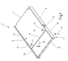
- FIG. 1 is illustrated in FIG. 1, which is used to manufacture sewing needles 2, 3, such as they are exemplified in Figure 7.
- the sewing needle 2 is straight, while the sewing needle 3 elongated, but curved in the shape of an arc is. Both types of needles can be in the package 1 according to Figure 1 and 1a are packed and shipped according to Figure 7.
- the packaging 1 according to FIG. 1 has one from FIG 4 apparent envelope 4 on the plastic for example manufactured in an injection molding process is.
- the receiving body 4 includes a receiving part 5 and a cover part 6, which are connected to one another via a film hinge 7 are connected.
- the film hinge is replaced by a linear area of significantly reduced material thickness (Wall thickness) formed, which covers almost the entire Width of the cover part 6 and the receiving part 5 extends.
- the receiving part 5 has a flat rectangular Floor section 8 on. From two opposite each other Edges 9, 10 of the bottom section 8 extend Side walls 11, 12 perpendicularly away.
- the bottom part 5 is in a movable receiving section 14 and one fixed receiving section 15 divided. For that are the Side walls 11, 12 in the area of a film hinge 16 interrupted by the bottom portion 8 of the Edge 9 extends to edge 10.
- the side walls 11, 12 are designed so that they are in the range of Film hinge 16 have a gap when the movable Receiving section 14 is aligned so that the entire bottom section 8 is kept level (i.e. stretched) is.
- the cover part 6 is essentially one rectangular rigid section formed by a Film hinge 17 in a fixed cover section 18 and dividing a movable lid section 19 is.
- the cover section 18 extends from the Film hinge 7 up to the film hinge 17 and points thereby a length that is greater than the length of the Receiving section 15 by the distance of the film hinge 7 be defined by the film hinge 16 can.
- the cover section 18 is provided with the receiving portion 15 to be connected.
- the side wall 11 has a locking groove 21 which parallel to the edge 9 near the top free Edge of the side wall 11 extends.
- the locking groove 21 runs on the inside of the side wall 11, starting from from the film hinge 7 to that of the film hinge 16 existing gap in the side wall 11.
- the formation of the locking groove 21 is in particular from Figure 5 can be seen.
- the cover section 18 on the receiving section 15 is the cover section 18 on his off the film hinge 7 provided extending edge with a locking rib 22, which has a cross section matching the locking groove 21.
- the locking groove 21 has a prismatic one Cross section and the locking rib 22 a triangular Cross section on.
- the side wall 12 provided that it is part of the receiving section 15 is. This is also the case here existing edge of the cover section 18 with a Provide locking rib. So that the locking device is the Side wall 12 is a mirror image of the locking device of the Sidewall 11 formed.
- the cover section 18 is in one in the closed state of the packaging 1, the film hinge 16 overlapping area on both sides each provided with a projection 25, 26, which is in each case in the gap in the side wall 11 or 12 extends into and an abutment for the receiving portion 14 forms.
- the projections 25, 26 are mirror images trained to each other, so that the following Description of the projection 26 accordingly for the Projection 25 applies.
- the projection 26 is trapezoidal in side view educated. It points to the film hinge 7 facing it Side an inclined surface 27, the corresponding one Sloping surface 28 on the end face of the side wall 12 is assigned.
- the inclined surfaces 27, 28 act as shown in Figure 3, as wedge surfaces. When merging run from cover part 6 and receiving part 5 the inclined surfaces 27, 28 against each other, whereby a firm contact of the projection 25, 26 on the side wall 11, 12 is reached and thereby the cover part 6 at least something is clamped away from the film hinge 7.
- Essential is that the projection 25, 26 without play on the relevant side wall 11, 12 abuts.
- the projections 25, 26 correspond in shape largely the respective gap in the side wall 11, 12.
- the side wall sections 11a, 12a of the receiving section 14 have on their projections 25, 26 facing End faces also inclined surfaces 29, that if the bottom 8 of the receiving part 5 is level, i.e. straight, is held on the corresponding wedge or Sloping surfaces of the projections 25, 26 abut.
- the receiving section 14 can indeed as in FIG. 3 illustrated, away from the cover part 6, but not beyond the extended position to the cover part 6 be folded up.
- the projections 25, 26 thus form Abutment for the receiving section 14. The latter is particularly evident from Figure 2.
- a connecting means is provided, which is formed by a latching device 31.
- a connecting means is formed by a latching device 31.
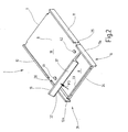
- the Snap tab overlaps at the free end of the Bottom 8 of the receiving portion 14 from the side wall portion 11a extending to the side wall portion 12a Footbridge 33. This is on its packaging 1 pointing side, as illustrated in Figure 2, with a locking recess 34 provided, one on the locking tab 32 trained rib-like latch 35 assigned is. This can be seen in Figure 4.
- the recess 34 is formed by a groove, into which the locking lug 35 under the spring action of the locking tab 32 can snap.
- a support step 36 provided that are parallel to the locking tab 32 over the inside of the cover section 19 extends. In the engaged state when the latch 35 the support step 36 is located in the latching recess 34 on the web 33.
- the latching tab 32 preferably with a recessed grip 37 Mistake.
- the locking tab 32 is on its side facing away from the packaging 1 is concave arched.
- Other grip aids such as knobs, Projections or the like are also possible.
- the packaging 1 described so far is stackable.
- the side walls 11, 12 are like FIG. 5 for the Sidewall 11 illustrates formed so that it protrude beyond the cover part 6.
- the locking groove 21 is in one such a distance from the upper edge of the side wall 11, that the side wall is at least a fraction protrudes a millimeter over the cover part 6.
- an open-edge stacking groove 38 is formed. This is designed to fit the top free edge of the relevant side walls 11, 12 of a similar packaging can record.
- FIG and 2 emerges on the cover section 18 locking pins or locking knobs 41, 42 provided, which correspond Locking openings 43, 44 (FIG. 4) in the bottom 8 assigned.
- the locking openings 43, 44 and the locking knobs 41, 42 are matched to one another so that corresponding Hold packages 1 together if the Locking knobs 41, 42 inserted into the locking openings 43, 44 are.
- a modified embodiment of the packaging 1 is illustrated as packaging 1a in Figures 6 and 7.
- the packaging 1 or 1a is handled as follows:
- the one illustrated in FIG. 4 is first used for the production Envelope 4 generated.
- the cover part 6 by snapping the locking ribs 22nd in the locking grooves 21 connected to the receiving part 5. This creates an enclosed receiving space 48
- the receiving space 48 is used to store the sewing needles 2 or 3 as illustrated in Figure 7.
- the sewing needles 2 or 3 can be used for the first one Closing (erecting) of the enveloping body 4 in the receiving space 48 can be introduced. To do this, the concerned elongated objects, for example the sewing needle 2 or the sewing needle 3, inserted into the receiving part 5. After the cover part 6 has completely locked in place with the Receiving part 5 are the sewing needles 2 or 3 in the receiving space 48 held.
- the sewing needles 2, 3 should be free of play in the receiving space 48 can be accommodated, an additional spring element such as a foam strip in the Recording space 48 are inserted. This is done by first sewing needles 2 or 3 into the receiving space 48 inserted and then a corresponding foam strip is placed on the sewing needles 2, 3. With the closing the cover part 6 and latching with the receiving part 5 the lid part 6 clamps the foam strips and the Sewing needles 2 and 3 in the receiving space 48 against the floor 8 firm.
- an additional spring element such as a foam strip in the Recording space 48 are inserted. This is done by first sewing needles 2 or 3 into the receiving space 48 inserted and then a corresponding foam strip is placed on the sewing needles 2, 3. With the closing the cover part 6 and latching with the receiving part 5 the lid part 6 clamps the foam strips and the Sewing needles 2 and 3 in the receiving space 48 against the floor 8 firm.
- the locking ribs 22 and locking grooves 21 hold the cover part 6 securely on the receiving part 5 and prevent bulging or Popping open of the package 1 under the effect of Foam strip.
- the packaging 1 can be loaded, by first closing it and then from the front forth by the receiving portion 14th and the cover section 19 is thus pivoted away from one another be that the receiving space 48 one-sided is open.
- the enveloping body 4 be completely closed by using the cover part 6 the receiving part 5 on the side walls 11, 12, and the Cover section 19 with the receiving section 14 is locked by means of the locking tab 32 (Fig. 1).
- the Packaging 1 is stable (stiff) in this state. Becomes a pressure on the receiving portion towards Exercised arrow F1 find the side sections 11a, 12a on the projections 25, 26 a fixed abutment and prevent any noteworthy deformation of the packaging 1. However, there is a force on the cover section 19 exercised in the direction of arrow F2, which prevents the Receiving section 14 overlapping latch tab 32 a Pivotal movement of the cover portion 19 and the receiving portion 14 unit formed. This in particular because the cover section 19 is measured from the film hinge 17 to the locking tab 32, shorter is as the receiving portion 14 measured from that Film hinge 17 up to the web 33.
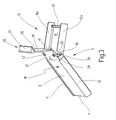
- the Receiving section 14 as illustrated in Figure 3 be pivoted away from the cover portion 19. This can happen with a thumb retraction.
- the protruding needles 2, 3 inside the receiving space 48 now with their ends out of the receiving space 48. she are easy to grasp and remove.
- the packaging 1 or 1a can be closed again in a simple manner, by the receiving portion 14 and the lid portion 19 (or 19a and 19b) moved towards each other again until the locking tab 32 is locked with the web 33.
- the packaging 1 is practical in this way Open and close as often as you like.
- a packaging 1 for packaging and ready elongated objects such as sewing needles 2, 3, has a receiving part 5 and a cover part 6, the are held together. Both the receiving part 5 and the cover part 6 also have at their respective head ends a formed as a flap section 14, 19, the towards and away from each other and the can be locked together. If the two flaps 14, 19 swung away from each other, they give out of the recording room 48 protruding ends of the sewing needles 2, 3 free, see above that they are easily pulled out of the receiving space 48 can be. This enables the sewing needles 2, 3, for example, in the receiving space 48 to back up.
Landscapes
- Engineering & Computer Science (AREA)
- Mechanical Engineering (AREA)
- Packaging Of Annular Or Rod-Shaped Articles, Wearing Apparel, Cassettes, Or The Like (AREA)
- Packages (AREA)
- Closures For Containers (AREA)
- Containers Having Bodies Formed In One Piece (AREA)
- Infusion, Injection, And Reservoir Apparatuses (AREA)
- Details Of Rigid Or Semi-Rigid Containers (AREA)
Abstract
Description
- Figur 1
- die erfindungsgemäße Verpackung in geschlossenem Zustand in perspektivischer Darstellung,
- Figur 2
- die Verpackung nach Figur 1 mit geöffnetem Deckelteilabschnitt in perspektivischer Darstellung,
- Figur 3
- die vollständig geöffnete Verpackung nach den Figuren 1 und 2 in perspektivischer Darstellung,
- Figur 4
- die Verpackung nach den Figuren 1 bis 3 nach der Herstellung ihres Hüllkörpers vor dem Verrasten des Deckelteils mit dem Aufnahmeteil in perspektivischer Darstellung,
- Figur 5
- die Verpackung nach Figur 4 in einer ausschnittsweisen perspektivischen Darstellung in einem anderen Maßstab,
- Figur 6
- eine abgewandelte Ausführungsform der erfindungsgemäßen Verpackung, teilweise geöffnet, in perspektivischer Darstellung und
- Figur 7
- die Verpackung nach Figur 6 vollständig geöffnet mit zwei beispielhaft dargestellten länglichen Nähnadeln in perspektivischer Darstellung.
- 1
- Verpackung
- 2, 3
- Nähnadel
- 4
- Hüllkörper
- 5
- Aufnahmeteil
- 6
- Deckelteil
- 7
- Filmscharnier
- 8
- Bodenabschnitt
- 9, 10
- Kanten
- 11, 12
- Seitenwände
- 14, 15
- Aufnahmeteilabschnitt
- 16, 17
- Filmscharniere
- 18, 19
- Deckelteilabschnitt
- 21
- Rastnut
- 22
- Rastrippe
- 25, 26
- Vorsprung
- 27
- Schrägfläche
- 28
- Schrägfläche
- 29
- Schrägfläche
- 31
- Rasteinrichtung
- 32
- Rastlasche
- 33
- Steg
- 34
- Rastausnehmung
- 35
- Rastnase
- 36
- Abstützstufe
- 37
- Griffmulde
- 38
- Stapelnut
- 41, 42
- Rastnöppen
- 43, 44
- Rastöffnungen
- 46
- Schlitz
- 48
- Aufnahmeraum
Claims (17)
- Verpackung (1), insbesondere für Nähmaschinennadeln (2, 3) oder dergleichen Gegenstände,wobei das Aufnahmeteil (5) einen beweglich gelagerten Aufnahmeteilabschnitt (14) aufweist,mit einem flachen Aufnahmeteil (5), das einen Aufnahmeraum (48) für die länglichen Gegenstände (2, 3) wenigstens einseitig begrenzt,mit einem flachen Deckelteil (6), in einem Abstand zu dem Aufnahmeteil (5) gehalten und mit diesem verbunden ist und das den Aufnahmeraum (48) an der dem Aufnahmeteil (5) gegenüberliegenden Seite begrenzt,
wobei das Deckelteil (6) einen beweglich gelagerten Deckelteilabschnitt (19) aufweist, und
wobei der Aufnahmeteilabschnitt (14) und der Deckelteilabschnitt (19) miteinander durch ein lösbares Verbindungsmittel (31) verbunden sind. - Verpackung nach Anspruch 1, dadurch gekennzeichnet, dass der Aufnahmeteilabschnitt (14) durch ein Scharniermittel (16) mit dem verbleibenden Aufnahmeteilabschnitt (15) verbunden ist, dass der Deckelteilabschnitt (19) durch ein Scharniermittel (17) mit dem verbleibenden Deckelteilabschnitt (18) verbunden ist und dass die Scharniermittel (16, 17) Schwenkachsen festlegen, die zueinander parallel ausgerichtet sind.
- Verpackung nach Anspruch 2, dadurch gekennzeichnet, dass die Scharniermittel (16, 17) als Filmscharniere ausgebildet sind.
- Verpackung nach Anspruch 1, dadurch gekennzeichnet, dass das Aufnahmeteil (5) einen flachen rechteckigen Bodenabschnitt (8) aufweist, der an zwei einander gegenüberliegenden, zueinander parallelen Kanten (9, 10) mit Seitenwänden (11, 12) versehen ist.
- Verpackung nach Anspruch 4, dadurch gekennzeichnet, dass an den Seitenwänden (11, 12) Mittel (21, 22) zur Befestigung des Deckelteils (6) an dem Aufnahmeteil (5) vorgesehen sind.
- Verpackung nach Anspruch 4, dadurch gekennzeichnet, dass die Seitenwände (11, 12) das Deckelteil (6) überragend ausgebildet sind und dass an der Kante (9, 10), bei der die Seitenwand (11, 12) mit dem Bodenabschnitt (8) des Aufnahmeteils (5) verbunden ist, eine Stapelnut (38) angeordnet ist.
- Verpackung nach Anspruch 5, dadurch gekennzeichnet, dass die Mittel (21, 22) Rastmittel sind.
- Verpackung nach Anspruch 1, dadurch gekennzeichnet, dass das Aufnahmeteil (5) und das Deckelteil (6) über ein Filmscharnier (7) miteinander verbunden sind.
- Verpackung nach Anspruch 1, dadurch gekennzeichnet, dass an dem Deckelteil (6) ein Widerlager (25, 26) für den Aufnahmeteilabschnitt (14) zur Begrenzung des Schwenkwinkels desselben vorgesehen ist.
- Verpackung nach Anspruch 9, dadurch gekennzeichnet, dass das Widerlager (25, 26) als Spanneinrichtung für das Deckelteil (6) ausgebildet ist.
- Verpackung nach Anspruch 4 und 10, dadurch gekennzeichnet, dass das Widerlager (25, 26) durch einen Vorsprung gebildet ist, der mit Keilflächen (28, 29) der Seitenwände (11, 12) zusammenwirkt.
- Verpackung nach Anspruch 9, dadurch gekennzeichnet, dass der Aufnahmeteilabschnitt (14) Seitenwandabschnitte (11a, 12a) aufweist, die mit dem Widerlager (25, 26) zusammenwirken, um sich an diesem abzustützen.
- Verpackung nach Anspruch 1, dadurch gekennzeichnet, dass der Aufnahmeraum (48) ungeteilt ausgebildet ist.
- Verpackung nach Anspruch 1, dadurch gekennzeichnet, dass an dem Deckelteilabschnitt (19) eine Rastlasche (32) aufweist, die dem Aufnahmeteilabschnitt (14) übergreifend ausgebildet ist.
- Verpackung nach Anspruch 1, dadurch gekennzeichnet, dass die Rastlasche (32) mit einer Griffmulde (37) versehen ist.
- Verpackung nach Anspruch 1, dadurch gekennzeichnet, dass der Deckelteilabschnitt (19) und/oder der Aufnahmeteilabschnitt (14) ungeteilt ausgebildet ist.
- Verpackung nach Anspruch 1, dadurch gekennzeichnet, dass die Gegenstände (2, 3) in dem Aufnahmeraum (48) reibschlüssig gesichert sind.
Applications Claiming Priority (2)
| Application Number | Priority Date | Filing Date | Title |
|---|---|---|---|
| DE10103130A DE10103130B4 (de) | 2001-01-24 | 2001-01-24 | Nadelverpackung |
| DE10103130 | 2001-01-24 |
Publications (2)
| Publication Number | Publication Date |
|---|---|
| EP1232963A1 true EP1232963A1 (de) | 2002-08-21 |
| EP1232963B1 EP1232963B1 (de) | 2006-02-15 |
Family
ID=7671592
Family Applications (2)
| Application Number | Title | Priority Date | Filing Date |
|---|---|---|---|
| EP01129467A Expired - Lifetime EP1232963B1 (de) | 2001-01-24 | 2001-12-11 | Nadelverpackung |
| EP02711777A Expired - Lifetime EP1353862B1 (de) | 2001-01-24 | 2002-01-23 | Nadelverpackung |
Family Applications After (1)
| Application Number | Title | Priority Date | Filing Date |
|---|---|---|---|
| EP02711777A Expired - Lifetime EP1353862B1 (de) | 2001-01-24 | 2002-01-23 | Nadelverpackung |
Country Status (7)
| Country | Link |
|---|---|
| US (2) | US6983847B2 (de) |
| EP (2) | EP1232963B1 (de) |
| JP (2) | JP3657560B2 (de) |
| AT (1) | ATE317814T1 (de) |
| DE (3) | DE10103130B4 (de) |
| ES (2) | ES2257376T3 (de) |
| WO (1) | WO2002059016A1 (de) |
Cited By (1)
| Publication number | Priority date | Publication date | Assignee | Title |
|---|---|---|---|---|
| EP2671821A1 (de) * | 2012-06-08 | 2013-12-11 | Groz-Beckert KG | Verpackung zur geordneten, ausgerichteten Aufbewahrung von Gegenständen und Verfahren zu deren Herstellung |
Families Citing this family (13)
| Publication number | Priority date | Publication date | Assignee | Title |
|---|---|---|---|---|
| DE10103130B4 (de) * | 2001-01-24 | 2005-12-15 | Groz-Beckert Kg | Nadelverpackung |
| US7243794B2 (en) * | 2004-07-30 | 2007-07-17 | Ta Ching Wang | Tattoo needle case with needle head protection arrangement |
| US7500562B2 (en) * | 2004-10-04 | 2009-03-10 | Nuclear Consultant Group, Inc. | Needle assembly holding tray |
| US20070012711A1 (en) * | 2005-07-18 | 2007-01-18 | Kutsch John H | Container for consumer article |
| DE102005036329A1 (de) * | 2005-07-29 | 2007-02-01 | Groz-Beckert Kg | Filznadelverpackung |
| US7571813B2 (en) * | 2005-10-05 | 2009-08-11 | Eveready Battery Company, Inc. | Fold back top package |
| WO2007091153A1 (en) * | 2006-02-08 | 2007-08-16 | Ricardo Sheath Oxford Steyn | Packaging container for a needle assembly |
| EP2123574B1 (de) | 2008-05-21 | 2010-11-03 | Groz-Beckert KG | Filznadelverpackung |
| JP5503881B2 (ja) * | 2009-02-27 | 2014-05-28 | 凸版印刷株式会社 | 防虫剤容器 |
| US8696540B2 (en) * | 2011-04-05 | 2014-04-15 | Best Medical International, Inc. | Apparatus and method to shield radiation needles |
| CN104291023B (zh) * | 2014-02-20 | 2018-02-23 | 沈益民 | 一次性加膜针灸针及其包装技术 |
| KR101747750B1 (ko) | 2017-01-23 | 2017-06-19 | 주식회사 다나메디컬 | 한방침 포장 구조 |
| KR102060011B1 (ko) * | 2019-02-28 | 2019-12-27 | 양판정 | 한방침 포장방법 및 그 한방침 |
Citations (4)
| Publication number | Priority date | Publication date | Assignee | Title |
|---|---|---|---|---|
| CH547744A (de) * | 1971-11-11 | 1974-04-11 | Morrall Ltd Abel | Verpackung fuer laengliche spitze gegenstaende, insbesondere fuer nadeln. |
| US3967730A (en) * | 1975-01-18 | 1976-07-06 | Techform, Inc. | Cigarette package |
| US5067611A (en) * | 1989-06-21 | 1991-11-26 | William Prym-Werke Gmbh & Co. Kg | Blister pack for storage of needles and the like |
| DE19646845C1 (de) | 1996-11-13 | 1998-02-12 | Groz Beckert Kg | Verpackung, insbesondere für Nähmaschinennadeln oder dergleichen längliche Gegenstände |
Family Cites Families (13)
| Publication number | Priority date | Publication date | Assignee | Title |
|---|---|---|---|---|
| GB1407399A (en) | 1971-11-11 | 1975-09-24 | Morrall Ltd Abel | Holders for needles pins and like articles |
| FR2174357A5 (de) * | 1972-02-29 | 1973-10-12 | Torrington Co | |
| JPS5715194Y2 (de) * | 1978-03-23 | 1982-03-29 | ||
| US4243141A (en) * | 1979-11-08 | 1981-01-06 | Bankoku Needle Manufacturing Company Ltd. | Needle pack |
| DE8511117U1 (de) * | 1985-04-16 | 1985-10-31 | Rösler, Peter, 7988 Wangen | Behälter mit einem Einsatzkörper zum Festlegen von länglichen Gegenständen |
| US5024323A (en) * | 1989-09-25 | 1991-06-18 | Bernard Bolton | Suture extender and needle guard |
| DE9115479U1 (de) * | 1991-12-13 | 1992-02-13 | William Prym-Werke GmbH & Co KG, 5190 Stolberg | Verkaufspackung für Nähnadeln o.dgl. |
| DE9307034U1 (de) * | 1993-05-08 | 1993-07-15 | Joh. Moritz Rump & Partner GmbH & Co. KG, 5990 Altena | Verkaufspackung für Handarbeitsnadeln, wie Stricknadeln |
| US5566822A (en) * | 1993-12-09 | 1996-10-22 | United States Surgical Corporation | Suture retainer |
| US6076669A (en) * | 1998-09-08 | 2000-06-20 | Hand Tool Design Corporation | Tool display rack |
| US6371300B1 (en) * | 1999-10-15 | 2002-04-16 | Toyo Chemical Co., Ltd. | Optical disc case |
| JP2001233368A (ja) * | 1999-12-17 | 2001-08-28 | Sony Corp | 収納ケース |
| DE10103130B4 (de) * | 2001-01-24 | 2005-12-15 | Groz-Beckert Kg | Nadelverpackung |
-
2001
- 2001-01-24 DE DE10103130A patent/DE10103130B4/de not_active Expired - Fee Related
- 2001-12-11 EP EP01129467A patent/EP1232963B1/de not_active Expired - Lifetime
- 2001-12-11 AT AT01129467T patent/ATE317814T1/de active
- 2001-12-11 DE DE50108950T patent/DE50108950D1/de not_active Expired - Lifetime
- 2001-12-11 ES ES01129467T patent/ES2257376T3/es not_active Expired - Lifetime
-
2002
- 2002-01-23 US US10/343,965 patent/US6983847B2/en not_active Expired - Lifetime
- 2002-01-23 JP JP2002014329A patent/JP3657560B2/ja not_active Expired - Fee Related
- 2002-01-23 WO PCT/DE2002/000220 patent/WO2002059016A1/de not_active Ceased
- 2002-01-23 EP EP02711777A patent/EP1353862B1/de not_active Expired - Lifetime
- 2002-01-23 JP JP2002559324A patent/JP3945701B2/ja not_active Expired - Lifetime
- 2002-01-23 DE DE50203618T patent/DE50203618D1/de not_active Expired - Lifetime
- 2002-01-23 ES ES02711777T patent/ES2244757T3/es not_active Expired - Lifetime
- 2002-04-15 US US10/121,576 patent/US6619476B2/en not_active Expired - Lifetime
Patent Citations (4)
| Publication number | Priority date | Publication date | Assignee | Title |
|---|---|---|---|---|
| CH547744A (de) * | 1971-11-11 | 1974-04-11 | Morrall Ltd Abel | Verpackung fuer laengliche spitze gegenstaende, insbesondere fuer nadeln. |
| US3967730A (en) * | 1975-01-18 | 1976-07-06 | Techform, Inc. | Cigarette package |
| US5067611A (en) * | 1989-06-21 | 1991-11-26 | William Prym-Werke Gmbh & Co. Kg | Blister pack for storage of needles and the like |
| DE19646845C1 (de) | 1996-11-13 | 1998-02-12 | Groz Beckert Kg | Verpackung, insbesondere für Nähmaschinennadeln oder dergleichen längliche Gegenstände |
Cited By (1)
| Publication number | Priority date | Publication date | Assignee | Title |
|---|---|---|---|---|
| EP2671821A1 (de) * | 2012-06-08 | 2013-12-11 | Groz-Beckert KG | Verpackung zur geordneten, ausgerichteten Aufbewahrung von Gegenständen und Verfahren zu deren Herstellung |
Also Published As
| Publication number | Publication date |
|---|---|
| DE50108950D1 (de) | 2006-04-20 |
| EP1353862A1 (de) | 2003-10-22 |
| JP2002234585A (ja) | 2002-08-20 |
| DE50203618D1 (de) | 2005-08-18 |
| ES2244757T3 (es) | 2005-12-16 |
| US6983847B2 (en) | 2006-01-10 |
| EP1232963B1 (de) | 2006-02-15 |
| JP2004517012A (ja) | 2004-06-10 |
| EP1353862B1 (de) | 2005-07-13 |
| WO2002059016A1 (de) | 2002-08-01 |
| ES2257376T3 (es) | 2006-08-01 |
| US6619476B2 (en) | 2003-09-16 |
| JP3945701B2 (ja) | 2007-07-18 |
| JP3657560B2 (ja) | 2005-06-08 |
| US20030127349A1 (en) | 2003-07-10 |
| DE10103130A1 (de) | 2002-08-08 |
| DE10103130B4 (de) | 2005-12-15 |
| ATE317814T1 (de) | 2006-03-15 |
| US20020112978A1 (en) | 2002-08-22 |
Similar Documents
| Publication | Publication Date | Title |
|---|---|---|
| DE2511240C2 (de) | Einstückiger, aus Kunststoff bestehender Binder für Kabel und dergleichen | |
| EP0194481B1 (de) | Behälter zur Aufbewahrung und Beförderung von Siliciumscheiben | |
| DE2427105C3 (de) | Behälter für Magnetbandkassetten | |
| DE2558849C2 (de) | Behälter | |
| DE3201487C2 (de) | ||
| EP1232963B1 (de) | Nadelverpackung | |
| DE69017051T2 (de) | System zum lagern. | |
| DE69305694T2 (de) | Mit einem Schiebeverschluss versehener Behälter | |
| DE7019006U (de) | Zum oeffnen und wiederverschliessen geeignete durchsichtige verpackung. | |
| DE69935270T2 (de) | Band-Verpackungssystem und Einrichtung zu dessen Zusammensetzung und Zerlegung | |
| DE9403713U1 (de) | Faltbare Verpackung für Waren | |
| EP0568729A2 (de) | Diskettenbox | |
| EP0842868B1 (de) | Verpackung, insbesondere für Nähmaschinennadeln oder dergleichen längliche Gegenstände | |
| DE3530632A1 (de) | Abheftvorrichtung fuer blattlagen | |
| DE112021008090T5 (de) | Kordelstopper | |
| DE3926062C2 (de) | ||
| EP2671821B1 (de) | Verpackung zur geordneten, ausgerichteten Aufbewahrung von Gegenständen und Verfahren zu deren Herstellung | |
| DE2220274C3 (de) | Karton zum Verpacken von Eiern u.dgl. | |
| CH413715A (de) | Verschlusszuschnitt zur Herstellung einer Verbindung zwischen sich überlappenden Teilen einer aus Band, Draht oder dergl. bestehenden Umschnürung | |
| EP0665170A1 (de) | Deckel für einen Behälter | |
| DE1814348A1 (de) | Ladekasten | |
| DE19536879A1 (de) | Aufbewahrungsbox zur Archivierung eines Daten- oder Tonträgers | |
| DE69203520T2 (de) | Ordner für Bögen mit Staubschutztasche. | |
| EP0257322A1 (de) | Vorrichtung zur Befestigung eines Beschlags an einem Anschlaggut | |
| DE19854097A1 (de) | Verpackungskarton |
Legal Events
| Date | Code | Title | Description |
|---|---|---|---|
| PUAI | Public reference made under article 153(3) epc to a published international application that has entered the european phase |
Free format text: ORIGINAL CODE: 0009012 |
|
| AK | Designated contracting states |
Kind code of ref document: A1 Designated state(s): AT BE CH CY DE DK ES FI FR GB GR IE IT LI LU MC NL PT SE TR |
|
| AX | Request for extension of the european patent |
Free format text: AL;LT;LV;MK;RO;SI |
|
| 17P | Request for examination filed |
Effective date: 20030122 |
|
| AKX | Designation fees paid |
Designated state(s): AT DE ES FR GB IT |
|
| 17Q | First examination report despatched |
Effective date: 20030902 |
|
| GRAP | Despatch of communication of intention to grant a patent |
Free format text: ORIGINAL CODE: EPIDOSNIGR1 |
|
| GRAS | Grant fee paid |
Free format text: ORIGINAL CODE: EPIDOSNIGR3 |
|
| GRAA | (expected) grant |
Free format text: ORIGINAL CODE: 0009210 |
|
| AK | Designated contracting states |
Kind code of ref document: B1 Designated state(s): AT DE ES FR GB IT |
|
| REG | Reference to a national code |
Ref country code: GB Ref legal event code: FG4D Free format text: NOT ENGLISH |
|
| GBT | Gb: translation of ep patent filed (gb section 77(6)(a)/1977) |
Effective date: 20060215 |
|
| REF | Corresponds to: |
Ref document number: 50108950 Country of ref document: DE Date of ref document: 20060420 Kind code of ref document: P |
|
| REG | Reference to a national code |
Ref country code: ES Ref legal event code: FG2A Ref document number: 2257376 Country of ref document: ES Kind code of ref document: T3 |
|
| ET | Fr: translation filed | ||
| PLBE | No opposition filed within time limit |
Free format text: ORIGINAL CODE: 0009261 |
|
| STAA | Information on the status of an ep patent application or granted ep patent |
Free format text: STATUS: NO OPPOSITION FILED WITHIN TIME LIMIT |
|
| 26N | No opposition filed |
Effective date: 20061116 |
|
| PGFP | Annual fee paid to national office [announced via postgrant information from national office to epo] |
Ref country code: AT Payment date: 20101214 Year of fee payment: 10 |
|
| REG | Reference to a national code |
Ref country code: AT Ref legal event code: MM01 Ref document number: 317814 Country of ref document: AT Kind code of ref document: T Effective date: 20121211 |
|
| PG25 | Lapsed in a contracting state [announced via postgrant information from national office to epo] |
Ref country code: AT Free format text: LAPSE BECAUSE OF NON-PAYMENT OF DUE FEES Effective date: 20121211 |
|
| REG | Reference to a national code |
Ref country code: FR Ref legal event code: PLFP Year of fee payment: 15 |
|
| PGFP | Annual fee paid to national office [announced via postgrant information from national office to epo] |
Ref country code: FR Payment date: 20151123 Year of fee payment: 15 Ref country code: ES Payment date: 20151127 Year of fee payment: 15 |
|
| REG | Reference to a national code |
Ref country code: FR Ref legal event code: ST Effective date: 20170831 |
|
| PG25 | Lapsed in a contracting state [announced via postgrant information from national office to epo] |
Ref country code: FR Free format text: LAPSE BECAUSE OF NON-PAYMENT OF DUE FEES Effective date: 20170102 |
|
| PG25 | Lapsed in a contracting state [announced via postgrant information from national office to epo] |
Ref country code: ES Free format text: LAPSE BECAUSE OF FAILURE TO SUBMIT A TRANSLATION OF THE DESCRIPTION OR TO PAY THE FEE WITHIN THE PRESCRIBED TIME-LIMIT Effective date: 20060215 |
|
| REG | Reference to a national code |
Ref country code: ES Ref legal event code: FD2A Effective date: 20180627 |
|
| PG25 | Lapsed in a contracting state [announced via postgrant information from national office to epo] |
Ref country code: ES Free format text: LAPSE BECAUSE OF FAILURE TO SUBMIT A TRANSLATION OF THE DESCRIPTION OR TO PAY THE FEE WITHIN THE PRESCRIBED TIME-LIMIT Effective date: 20161212 |
|
| PGFP | Annual fee paid to national office [announced via postgrant information from national office to epo] |
Ref country code: GB Payment date: 20181205 Year of fee payment: 18 |
|
| PGFP | Annual fee paid to national office [announced via postgrant information from national office to epo] |
Ref country code: DE Payment date: 20181231 Year of fee payment: 18 Ref country code: IT Payment date: 20181220 Year of fee payment: 18 |
|
| REG | Reference to a national code |
Ref country code: DE Ref legal event code: R119 Ref document number: 50108950 Country of ref document: DE |
|
| GBPC | Gb: european patent ceased through non-payment of renewal fee |
Effective date: 20191211 |
|
| PG25 | Lapsed in a contracting state [announced via postgrant information from national office to epo] |
Ref country code: GB Free format text: LAPSE BECAUSE OF NON-PAYMENT OF DUE FEES Effective date: 20191211 Ref country code: DE Free format text: LAPSE BECAUSE OF NON-PAYMENT OF DUE FEES Effective date: 20200701 Ref country code: IT Free format text: LAPSE BECAUSE OF NON-PAYMENT OF DUE FEES Effective date: 20191211 |