EP1043774B1 - Semiconductor integrated circuit - Google Patents
Semiconductor integrated circuit Download PDFInfo
- Publication number
- EP1043774B1 EP1043774B1 EP98961441A EP98961441A EP1043774B1 EP 1043774 B1 EP1043774 B1 EP 1043774B1 EP 98961441 A EP98961441 A EP 98961441A EP 98961441 A EP98961441 A EP 98961441A EP 1043774 B1 EP1043774 B1 EP 1043774B1
- Authority
- EP
- European Patent Office
- Prior art keywords
- circuit
- voltage
- supply
- substrate
- power
- Prior art date
- Legal status (The legal status is an assumption and is not a legal conclusion. Google has not performed a legal analysis and makes no representation as to the accuracy of the status listed.)
- Expired - Lifetime
Links
Images


Classifications
-
- H—ELECTRICITY
- H01—ELECTRIC ELEMENTS
- H01L—SEMICONDUCTOR DEVICES NOT COVERED BY CLASS H10
- H01L27/00—Devices consisting of a plurality of semiconductor or other solid-state components formed in or on a common substrate
- H01L27/02—Devices consisting of a plurality of semiconductor or other solid-state components formed in or on a common substrate including semiconductor components specially adapted for rectifying, oscillating, amplifying or switching and having at least one potential-jump barrier or surface barrier; including integrated passive circuit elements with at least one potential-jump barrier or surface barrier
- H01L27/04—Devices consisting of a plurality of semiconductor or other solid-state components formed in or on a common substrate including semiconductor components specially adapted for rectifying, oscillating, amplifying or switching and having at least one potential-jump barrier or surface barrier; including integrated passive circuit elements with at least one potential-jump barrier or surface barrier the substrate being a semiconductor body
-
- H—ELECTRICITY
- H01—ELECTRIC ELEMENTS
- H01L—SEMICONDUCTOR DEVICES NOT COVERED BY CLASS H10
- H01L27/00—Devices consisting of a plurality of semiconductor or other solid-state components formed in or on a common substrate
- H01L27/02—Devices consisting of a plurality of semiconductor or other solid-state components formed in or on a common substrate including semiconductor components specially adapted for rectifying, oscillating, amplifying or switching and having at least one potential-jump barrier or surface barrier; including integrated passive circuit elements with at least one potential-jump barrier or surface barrier
- H01L27/0203—Particular design considerations for integrated circuits
- H01L27/0207—Geometrical layout of the components, e.g. computer aided design; custom LSI, semi-custom LSI, standard cell technique
-
- G—PHYSICS
- G11—INFORMATION STORAGE
- G11C—STATIC STORES
- G11C5/00—Details of stores covered by group G11C11/00
- G11C5/14—Power supply arrangements, e.g. power down, chip selection or deselection, layout of wirings or power grids, or multiple supply levels
-
- G—PHYSICS
- G11—INFORMATION STORAGE
- G11C—STATIC STORES
- G11C5/00—Details of stores covered by group G11C11/00
- G11C5/14—Power supply arrangements, e.g. power down, chip selection or deselection, layout of wirings or power grids, or multiple supply levels
- G11C5/145—Applications of charge pumps; Boosted voltage circuits; Clamp circuits therefor
- G11C5/146—Substrate bias generators
-
- G—PHYSICS
- G11—INFORMATION STORAGE
- G11C—STATIC STORES
- G11C5/00—Details of stores covered by group G11C11/00
- G11C5/14—Power supply arrangements, e.g. power down, chip selection or deselection, layout of wirings or power grids, or multiple supply levels
- G11C5/147—Voltage reference generators, voltage or current regulators; Internally lowered supply levels; Compensation for voltage drops
-
- H—ELECTRICITY
- H01—ELECTRIC ELEMENTS
- H01L—SEMICONDUCTOR DEVICES NOT COVERED BY CLASS H10
- H01L27/00—Devices consisting of a plurality of semiconductor or other solid-state components formed in or on a common substrate
- H01L27/02—Devices consisting of a plurality of semiconductor or other solid-state components formed in or on a common substrate including semiconductor components specially adapted for rectifying, oscillating, amplifying or switching and having at least one potential-jump barrier or surface barrier; including integrated passive circuit elements with at least one potential-jump barrier or surface barrier
- H01L27/04—Devices consisting of a plurality of semiconductor or other solid-state components formed in or on a common substrate including semiconductor components specially adapted for rectifying, oscillating, amplifying or switching and having at least one potential-jump barrier or surface barrier; including integrated passive circuit elements with at least one potential-jump barrier or surface barrier the substrate being a semiconductor body
- H01L27/08—Devices consisting of a plurality of semiconductor or other solid-state components formed in or on a common substrate including semiconductor components specially adapted for rectifying, oscillating, amplifying or switching and having at least one potential-jump barrier or surface barrier; including integrated passive circuit elements with at least one potential-jump barrier or surface barrier the substrate being a semiconductor body including only semiconductor components of a single kind
- H01L27/085—Devices consisting of a plurality of semiconductor or other solid-state components formed in or on a common substrate including semiconductor components specially adapted for rectifying, oscillating, amplifying or switching and having at least one potential-jump barrier or surface barrier; including integrated passive circuit elements with at least one potential-jump barrier or surface barrier the substrate being a semiconductor body including only semiconductor components of a single kind including field-effect components only
- H01L27/088—Devices consisting of a plurality of semiconductor or other solid-state components formed in or on a common substrate including semiconductor components specially adapted for rectifying, oscillating, amplifying or switching and having at least one potential-jump barrier or surface barrier; including integrated passive circuit elements with at least one potential-jump barrier or surface barrier the substrate being a semiconductor body including only semiconductor components of a single kind including field-effect components only the components being field-effect transistors with insulated gate
- H01L27/092—Devices consisting of a plurality of semiconductor or other solid-state components formed in or on a common substrate including semiconductor components specially adapted for rectifying, oscillating, amplifying or switching and having at least one potential-jump barrier or surface barrier; including integrated passive circuit elements with at least one potential-jump barrier or surface barrier the substrate being a semiconductor body including only semiconductor components of a single kind including field-effect components only the components being field-effect transistors with insulated gate complementary MIS field-effect transistors
- H01L27/0928—Devices consisting of a plurality of semiconductor or other solid-state components formed in or on a common substrate including semiconductor components specially adapted for rectifying, oscillating, amplifying or switching and having at least one potential-jump barrier or surface barrier; including integrated passive circuit elements with at least one potential-jump barrier or surface barrier the substrate being a semiconductor body including only semiconductor components of a single kind including field-effect components only the components being field-effect transistors with insulated gate complementary MIS field-effect transistors comprising both N- and P- wells in the substrate, e.g. twin-tub
-
- H—ELECTRICITY
- H01—ELECTRIC ELEMENTS
- H01L—SEMICONDUCTOR DEVICES NOT COVERED BY CLASS H10
- H01L27/00—Devices consisting of a plurality of semiconductor or other solid-state components formed in or on a common substrate
- H01L27/02—Devices consisting of a plurality of semiconductor or other solid-state components formed in or on a common substrate including semiconductor components specially adapted for rectifying, oscillating, amplifying or switching and having at least one potential-jump barrier or surface barrier; including integrated passive circuit elements with at least one potential-jump barrier or surface barrier
- H01L27/04—Devices consisting of a plurality of semiconductor or other solid-state components formed in or on a common substrate including semiconductor components specially adapted for rectifying, oscillating, amplifying or switching and having at least one potential-jump barrier or surface barrier; including integrated passive circuit elements with at least one potential-jump barrier or surface barrier the substrate being a semiconductor body
- H01L27/10—Devices consisting of a plurality of semiconductor or other solid-state components formed in or on a common substrate including semiconductor components specially adapted for rectifying, oscillating, amplifying or switching and having at least one potential-jump barrier or surface barrier; including integrated passive circuit elements with at least one potential-jump barrier or surface barrier the substrate being a semiconductor body including a plurality of individual components in a repetitive configuration
- H01L27/118—Masterslice integrated circuits
- H01L27/11803—Masterslice integrated circuits using field effect technology
- H01L27/11807—CMOS gate arrays
-
- H—ELECTRICITY
- H03—ELECTRONIC CIRCUITRY
- H03K—PULSE TECHNIQUE
- H03K19/00—Logic circuits, i.e. having at least two inputs acting on one output; Inverting circuits
- H03K19/0008—Arrangements for reducing power consumption
- H03K19/0016—Arrangements for reducing power consumption by using a control or a clock signal, e.g. in order to apply power supply
-
- H—ELECTRICITY
- H01—ELECTRIC ELEMENTS
- H01L—SEMICONDUCTOR DEVICES NOT COVERED BY CLASS H10
- H01L2924/00—Indexing scheme for arrangements or methods for connecting or disconnecting semiconductor or solid-state bodies as covered by H01L24/00
- H01L2924/0001—Technical content checked by a classifier
- H01L2924/0002—Not covered by any one of groups H01L24/00, H01L24/00 and H01L2224/00
Definitions
- the present invention relates to a semiconductor IC unit, more particularly to a semiconductor IC unit provided with both fast operation and low power consumption properties.
- CMOS integrated circuits are used widely to form a semiconductor IC unit such as a microprocessor, etc.
- a CMOS IC consumes an electric power in two ways; dynamic power consumption and static power consumption.
- the dynamic power consumption is caused by charging and discharging at a switching time and the static power consumption is caused by a subthreshold leakage current.
- the dynamic power consumption consumes a large current in proportion to the square of a supply voltage VDD, so the supply voltage should be lowered to save the power consumption of the object CMOS IC effectively. In recent years, the supply voltage is thus getting lower and lower to cope with such an object.
- some of the power-saving microprocessors available at present are provided with a power management feature and its processor is provided with a plurality of operation modes, so that supply of the clock to an active unit is stopped at its standby time according to the set operation mode.
- CMOS circuit drops at a low supply voltage.
- the threshold voltage of the MOS transistor must be lowered in conjunction with the drop of the supply voltage. If a threshold voltage is lowered, however, the subthreshold leakage current increases extremely. And, as the supply voltage is getting lower, the static power consumption increases more remarkably due to the subthreshold leakage current, which has not been so much conventionally. This is why it is now urgently required to realize a semiconductor IC unit such as a microprocessor, which can satisfy both fast operation and low power consumption properties.
- the substrate bias is set to the power source potential for PMOS (P-channel MOS transistors) and the ground potential for NMOS (N-channel MOS transistors) in the active state when the object CMOS circuit is required for a fast operation.
- the substrate bias is set to a potential higher than the supply voltage for PMOS and lower than the supply voltage for NMOS (hereafter, this operation will often be referred to as "applying a bias voltage to a substrate").
- US 5 659 517 discloses a semiconductor memory device as indicated in the preamble of claim 1.
- MOS transistors Q1 and Q2 conduct in response to an operation cycle definding signal and connect electrically a main power source line and a sub power source line.
- Q1 is coupled between the main power source line and the sub power source line, and
- Q2 is coupled between the sub ground line and the main ground line.
- JP 08-249882A discloses a semiconductor integrated circuit in which a substrate voltage detection circuit, an oscillation circuit and a voltage generation circuit are provided to supply a specified substrate back biassing voltage to the substrate.
- EP 0573009A1 discloses a semiconductor device in which the substrate bias generating circuit is controlled via an I/O-circuit. The bias supplied to the substrate and the p-type well region is varied in accordance with the operation mode of the main circuit.
- the substrate bias In order to materialize a semiconductor IC unit such as a microprocessor, etc., which can satisfy both fast operation and lower power consumption properties, the substrate bias must be controlled as described above for each CMOS circuit so that the threshold voltage of the MOS transistors is lowered when the semiconductor IC unit is active and raised when the semiconductor IC unit stands by, thereby reducing the subthreshold leakage current.
- the present invention has proposed the following means mainly.
- the output of the negative voltage generating circuit is connected to a pad.
- the negative voltage generating circuit must be checked for if a preset voltage level is reached as its output signal.
- the negative voltage generating circuit should be provided with a terminal from which the signal is output as it is.
- a plurality of substrate MOS transistors are provided in the main circuit used for controlling the substrate bias.
- the substrate driving MOS transistors are used to drive the substrate bias when the semiconductor IC unit is active. This is because the impedance must be lowered to fix the substrate potential and suppress the variance of the transistor threshold level when the IC circuit is active, thereby enabling the respective circuits in the main circuit to operate.
- the driving power of the semiconductor IC unit increases in the active state more than in the standby state.
- the driving power should thus be 5 times.
- it should be 10 times that in the standby state.
- each circuit becomes unstable when the substrate bias is switched over.
- the gate control signal used for controlling the gate voltage of a substrate driving MOS transistor is wired so that the control signal, after being connected to the substrate driving MOS transistor, is returned to the substrate bias controlling circuit and the potential of the returned signal is used by the substrate bias controlling circuit to detect that the main circuit substrate bias is stabilized.
- the semiconductor IC unit is provided with a power-on resetting circuit.
- the power-on resetting circuit detects that the main circuit is powered.
- the semiconductor IC unit is kept in the active state so that each substrate driving MOS transistor drives the substrate bias shallowly for a fixed time after the main circuit is powered.
- the substrate bias controlling circuit controls the output impedance of the gate control signal so as to become larger than the impedance to be set after the semiconductor IC unit enters the active state completely.
- the semiconductor IC unit is also provided with a negative voltage generating circuit.
- the substrate bias controlling circuit controls the output impedance of the negative voltage generating circuit in the standby state so as to be smaller than the output impedance in the active state.
- the main circuit comprises a plurality of cells. Those cells compose a power-supply net, which is powered by the first metal levels. Another power-supply net is formed with the second wiring layers, which are orthogonal to the first metal levels. And, a switch cell is disposed at each intersection point of the power-supply nets formed with the first and second wiring layers. The power-supply nets of the first and second wiring layers are connected to each other in the switch cells. A substrate driving MOS transistor described above is disposed in each of those switch cells.
- the substrate bias supply line of a MOS transistor composing one of the above cells is formed with the first metal levels, which are in parallel to the power-supply net formed with the first metal levels, as well as by the second wiring layers in parallel to the power-supply net formed with the second wiring layers.
- the substrate bias supply line formed with the first metal levels is connected to the substrate bias supply line formed with the second wiring layers in each of the switch cells, thereby the gate control signal for controlling the gate voltage of each substrate drive MOS transistor is supplied by the second wiring layers above the switch cell, in parallel to the power-supply net formed by the second wiring layers.
- the gate control signal is then connected to the gate terminal of the substrate drive MOS transistor in a switch cell described above.
- the semiconductor IC unit of the present invention is defined by claim 1. It comprises a main circuit composed of at least one transistor; a substrate bias controlling circuit used for controlling a voltage to be applied to each transistor substrate; and a standby controlling circuit used for switching between at least two states; active and standby.
- the substrate bias controlling circuit In the active state, the substrate bias controlling circuit is controlled to increase the subthreshold leakage current flowing in the main circuit.
- the standby state the bias controlling circuit is controlled to decrease the subthreshold leakage current.
- the semiconductor IC circuit is also provided with a negative voltage generating circuit, which is incorporated in the substrate bias controlling circuit, as well as a terminal for outputting a negative voltage generated from the negative voltage generating circuit to external.
- the semiconductor IC unit is provided with a semiconductor chip having output pads, and a package incorporating the semiconductor chip in itself and having external pins, wherein one of the output pads is used as a terminal, which is not connected to any external pin.
- the semiconductor IC unit is provided with a main circuit composed of at least one MOS transistor, a substrate bias controlling circuit used for controlling a voltage applied to the substrate of the MOS transistor, a standby controlling circuit used for switching the semiconductor IC unit between at least two states of active and standby.
- the active state allows much subthreshold leakage current to flow in the main circuit and the standby state allows less subthreshold leakage current to flow in the main circuit.
- the semiconductor IC unit thus controls the substrate bias shallowly in the active state and deeply in the standby state, so that the power for driving the substrate bias shallowly in the active state becomes 10 times or over larger than the power for driving the substrate bias deeply in the standby state.
- the substrate bias When the substrate bias is controlled deeply, it should preferably be avoided to operate the main circuit composed of transistors whose substrate is applied a bias voltage respectively.
- a bias voltage When a bias voltage is applied to the substrate of a transistor, the substrate impedance is high. If a MOS transistor is activated, therefore, the substrate potential is easily changed. Consequently, the MOS transistor will probably malfunction in such a case.
- At least two MOS transistors are used for driving the substrate bias shallowly in the active state. Those MOS transistors are disposed at a distance of 20 ⁇ m or over from each other. The gate potential of each of the substrate driving MOS transistors is controlled by the substrate bias controlling circuit.
- the gate control signal used for controlling the gate voltage of the substrate driving MOS transistors is returned to the substrate bias controlling circuit after it is connected to the gate of each of the substrate driving MOS transistors. After this, according to the potential of the returned signal, the substrate bias controlling circuit can detect that the substrate bias applied to the main circuit is stabilized.
- the threshold voltage of the substrate driving MOS transistors should be set larger than the threshold level of the MOS transistors composing the main circuit.
- the semiconductor IC unit is provided with an I/O circuit used for interfacing with external, at least one of the MOS transistors composing the I/O circuit should preferably be coated with an oxidization film thicker than the oxidization film of the MOS transistors composing the main circuit.
- the withstand voltage should preferably be set high at portions to which a high voltage is applied.
- the semiconductor IC unit is further provided with a power-on resetting circuit used for detecting that the main circuit is powered.
- the active state is kept for a fixed time after the main circuit is powered. In the active state, each substrate MOS transistor drives the substrate bias shallowly.
- the semiconductor IC unit is provided with two supply voltages; the first (VDDQ) and the second (VDD).
- the first supply voltage has its absolute value larger than that of the second supply voltage, which is 2V or under.
- the second supply voltage (VDD) is supplied to the main circuit (LOG) and the first supply voltage (VDDQ) is supplied to both substrate bias controlling circuit (VBC) and standby controlling circuit (VBCC).
- VBC substrate bias controlling circuit
- VBCC standby controlling circuit
- the first supply voltage is applied earlier than the second supply voltage.
- the substrate bias controlling circuit controls so as to keep the main circuit in the active state for a fixed time after the substrate bias controlling circuit is applied the second supply voltage.
- the output impedance of the gate control signal of the substrate driving MOS transistors in a process in which the state is shifted from standby to active is set higher than that after the state is already set in the active state, it becomes possible to adjust the speed for shifting the state from standby to active so as to suppress the inrush current low in the shifting process.
- the output impedance of the gate control signal of the substrate driving MOS transistors in a process in which the state is shifted from standby to active is set higher than that after the state is already set in the active state, it becomes possible to adjust the speed for shifting the state from standby to active so as to suppress the inrush current low in the shifting process. It also becomes possible to detect by the returned signal that the main circuit is already set in the active state.
- the semiconductor IC unit is provided with a negative voltage generating circuit, so that the substrate bias controlling circuit can control the output impedance of the negative voltage generating circuit in the standby state lower than that in the active state.
- the negative voltage generating circuit is provided with the first and second charging pump circuits, so that the substrate bias controlling circuit uses the first charging pump circuit in the standby state and the second charging pump circuit in the active state thereby to generate a negative voltage respectively.
- the pumping capacitor of the first charging pump is set smaller than that of the second charging pump circuit.
- the negative voltage generating circuit is provided with at least a charging pump circuit, a comparator, the first reference voltage circuit used for generating a potential of a half of the second supply voltage one, and the second reference voltage circuit used for generating an intermediate potential between the first and third supply voltages.
- the comparator compares the voltage output from the first reference voltage circuit with the voltage output from the second reference voltage generating circuit thereby controlling at least one of the charging pumps to stabilize the third supply voltage.
- the first and second reference voltage generating circuits are composed respectively of a serial circuit in which same type conductor MOS transistors are connected serially. In each of the conductor MOS transistors, the substrate terminal is connected to the source terminal and the gate terminal is connected to the drain terminal.
- Each of the first and second reference voltage generating circuits can be selected so as to operate a plurality of MOS transistors in a saturation area. It may also be composed so as to have Schmitt characteristics.
- the main circuit is composed of a plurality of cells.
- a power-supply net for those cells is powered by the first metal levels.
- Another power-supply net is formed with the second wiring layer above those first metal levels so as to be orthogonal to those first metal levels.
- a switch cell is disposed at each intersection point of the power-supply nets formed with the first and second wiring layers, so that both power-supply nets formed with the first and second wiring layers are connected to each other in such the switch cells.
- a substrate driving MOS transistor is disposed in each of those switch cells.
- a switch cell may also be composed so as to dispose a decoupling capacitor between a power source and a ground.
- a power-supply net formed with the fourth wiring layers which are in parallel to the power-supply net formed with the second wiring layers.
- the power-supply nets formed with the second and fourth wiring layers may be connected to each other outside those switch cells.
- the power-supply net is connected to the power-supply net formed with the fourth wiring layers in switch cells.
- a power source mesh formed with the power-supply nets of the fourth and fifth wiring layers may be rougher than the power source mesh formed with the power-supply nets formed with the first and second wiring layers.
- the fourth and fifth wiring layers may be thicker than any of the first and second wiring layers.
- the substrate bias supply lines of the MOS transistors composing cells respectively may be formed with the first metal levels in parallel to the power-supply net formed with the first metal levels, as well as in parallel to the power-supply net formed with the second wiring layers.
- the substrate bias supply lines formed with the first metal levels may be connected to the substrate bias supply lines formed with the second wiring layers in switch cells.
- the gate control signal used for controlling the gate voltage of each of the substrate driving MOS transistors may be supplied by the second wiring layers formed above switch cells, which are disposed in parallel to the power-supply net formed with the second wiring layers and connected to the gate terminal of each of the substrate driving MOS transistors in a switch cell.
- the substrate bias supply lines wired by the second wiring layers above the switch cells and the gate control may be disposed between the power-supply nets wired by the second wiring layers above switch cells.
- the semiconductor IC unit of the present invention is also provided with a data path circuit.
- the data flowing direction of the data path circuit may be in parallel to the power-supply net wired by the first metal levels used for a plurality of cells.
- the substrate bias can be set so as to raise the threshold level of at least one MOS transistor when the semiconductor IC unit of the present invention is selected.
- the first pumping capacitor, the first P-channel transistor, and the first N-channel transistor are used for pumping the electric charge of the first pumping capacitor when the output of the oscillating circuit is 'H' and the second pumping capacitor, the second P-channel transistor, and the second N-channel transistor are used for pumping the electric charge of the second pumping capacitor when the output of the oscillating circuit is 'L'.
- the semiconductor IC unit is provided with a main circuit (LOG) including transistors composed on a semiconductor substrate respectively and a substrate bias controlling circuit (VBC) used for controlling a voltage to be applied to each substrate.
- the main circuit is provided with switch transistors (MN1 and MP1) used for controlling a voltage to be applied to each substrate and receives control signals output from the substrate bias controlling circuit through the gate of each of the switch transistors.
- the control signals may be composed so as to be returned to the substrate bias controlling circuit.
- Each switch transistor is disposed in a rectangular switch cell and each of other transistors is disposed in a rectangular standard cell.
- a switch cell and a standard cell should preferably be disposed side by side in terms of the layout.
- the power sources (VSS and VDD) used for driving the transistors (MN2 and MP2) in the main circuit, as well as the power sources (vbp and vbn) of the substrate bias supplied from the substrate bias controlling circuit should preferably be wired so as to cross both switch cells and standard cells vertically in the direction those cells are disposed.
- the threshold level of the switch transistors should preferably be larger than that of other transistors in terms of the transistor resistance.
- the switch transistors (MN1 and MP1) should preferably be inserted between the driving power sources (VSS and VDD) for the transistors in the main circuit and the power sources (vbp and vbn) of the substrate bias supplied from the substrate bias controlling circuit in terms of the layout.
- each transistor can be connected to the driving power sources (VSS and VDD) and the transistor substrate potential can be connected to the substrate bias power sources (vbp and vbn).
- the substrate bias controlling circuit can detect that control signals (vbp and vbn), after they are output, have been returned via the main circuit as control signals (vbpr and vbnr), then have reached a predetermined voltage. Then, the substrate bias controlling circuit can generate a detection signal (vbbenbr), thereby stabilizing the operation of the main circuit.
- Fig. 1 shows a block diagram of a semiconductor IC unit 100 that uses a substrate bias controlling circuit of the present invention.
- VBC is a substrate bias controlling circuit.
- LOG is the main circuit whose substrate bias is controlled.
- the LOG is composed of logic circuits and memory circuits.
- VBCC is a standby controlling circuit used to control the substrate bias controlling circuit.
- I/O is an I/O circuit used to interface between the semiconductor IC unit 100 and external. Wirings between circuit blocks, which are not needed specially for substrate controlling, are omitted here.
- 109a and 109b are substrate driving circuits.
- the semiconductor IC unit is provided with three types of power sources indicated as VDDQ, VDD, and VWELL.
- VSS and VSSQ are ground potentials used for VDD and VDDQ.
- VDDQ and VSSQ are power sources used for the I/O circuit.
- VDD and VSS are power sources used for the main circuit.
- VWELL is a power source used for the substrate bias controlling circuit VBC.
- VDD and VSS are also supplied to the substrate bias controlling circuit VBC.
- the substrate bias controlling circuit VBC incorporates a negative voltage generating circuit in it, generating a negative voltage VSUB which is inverse in polarity from VDDQ.
- VSUB -1.5V.
- 101, 102, 103, and 104 are pads of the semiconductor IC unit.
- the pad 102 is supplied 3.3V from VWELL, the pad 103 is supplied 1.8V from VDD, and the pad 104 is supplied 0V from VSS (ground) respectively.
- 101 is a VSUB pad, but it is used to output a negative voltage generated from inside the substrate bias controlling circuit.
- the voltage of the pad 101 can be monitored to detect errors of the negative voltage generating circuit provided in the substrate bias controlling circuit VBC when in a wafer test of the semiconductor IC unit 100.
- pads 102 to 104 are bonded to external pins of the semiconductor IC unit 100, but the pad 101 is not bonded to any outer pin. With this testing method, the number of external pins can be saved.
- vbbenb is a signal used for starting substrate bias controlling and vbbenbr is a signal indicating that the substrate bias is now being controlled.
- reset is a RESET signal connected to the RESET signal of the semiconductor IC unit.
- vbp is a PMOS substrate bias line
- vbn is an NMOS substrate bias line
- cbp is a PMOS substrate control line
- cbn is an NMOS substrate control line
- cbpr is a PMOS substrate control return line
- cbnr is an NMOS substrate control return line.
- the substrate control return lines cbpr and cbnr are used for signals returned after both cbp and cbn signals pass through the main circuit.
- both drive voltages cbp and cbn appear in cbpr and cbnr after a delay. (See Fig. 2 to be shown later.)
- To each of the substrate driving circuits 109a and 109b are connected cbp, vbp, cbn, and vbn respectively.
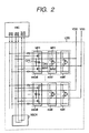
- Fig.2 shows how 6 substrate bias control lines (vbp to cbnr) are connected in the main circuit LOG.
- VBCR is a return cell.
- the PMOS substrate control line cbp is connected to the PMOS substrate control return line cbpr, as well as the NMOS substrate control line cbn is connected to the NMOS substrate control return line cbnr.
- ncell is a standard cell.
- every ncell is shown as a CMOS inverter composed of PMOS MP2 and NMOS MN2 to simplify the description.
- every ncell may be more complicated in structure like a cell composed of a NAND gate, a latch, etc. independently of others.
- the substrate potential of each MOS transistor is connected to vbp for PMOS and vbn for NMOS respectively. Those MOS transistors are composing an ncell respectively as shown in Fig.2.
- swcell is a switch cell composed of substrate driving circuits (equivalent to 109a and 109b shown in Fig.1) composed of PMOS MP1 and NMOS MN1, as well as decoupling capacitors CP1 and CP2 respectively.
- the gate is connected to cbp
- the drain is connected to VBP
- the source is connected to VDD. Consequently, when the cbp voltage is lower than VDD-Vthp (Vthp: an absolute value of the MP1 threshold voltage), MP1 is activated and vbp is driven into the VDD potential (1.8V).
- the gate, drain, and source of the MN1 are connected to cbn, VBN, and VSS (0V) respectively. Consequently, when the cbn voltage is higher than Vthn (Vthn: an absolute value of the MN1 threshold voltage), the MN1 is activated and the vbn is driven into the VSS potential (0V).
- Vthn an absolute value of the MN1 threshold voltage
- ncell is disposed more than one. So does swcell.
- the number of ncells can be increased to integrate complicated circuits in the main circuit LOG.
- the number of swcells can also be increased to drive the MP1 and MN1 into a lower impedance respectively when they are activated, as well as vbp and vbn can be driven into VDD and VSS.
- another decoupling capacitor can also be incorporated in a space cell independently of the above one.
- a space cell means a cell inserted in a space reserved for a wiring area, for example, when standard cells are to be disposed side by side. If a decoupling capacitor is incorporated in such a space cell, the total capacity of the decoupling capacitors on the whole chip is increased, thereby reducing the power source noise more significantly. Since a space cell is a free space provided just in a wiring layer originally, the space is not increased even when a capacitor is inserted there.
- Both MP1 and MN1 in a swcell must be set to a threshold value higher than that of a MOS transistor in an ncell.
- the reason is as follows; although the MOS transistor substrate potential (connected to vbp or vbn) in an ncell is independent of the source potential, the substrate potentials of both MP1 and MN1 in the swcell are always the same as the drain potential, thereby no substrate bias effect is expected. A subthreshold leakage current thus flows in the semiconductor IC unit.
- Fig.3 shows an embodiment for the I/O circuit.
- the I/O circuit inputs and outputs signals to and from the chip via an input/output terminal PAD. If SEL is 'L', the PAD functions as an input terminal. If SEL is 'H', the PAD functions as an output terminal.
- LC1 is a level converting circuit used to convert a VDD amplitude signal to a VDDQ amplitude signal. The VDDQ amplitude is larger than the VDD amplitude. Consequently, a thick oxidization film transistor is provided between the level converting cell LC1 and the input/output terminal PAD. The thick oxidization film transistor is driven by VDDQ.
- SEL is set to 'L' thereby to pull up the PULL using a PMOS pull-up transistor. This is done only when the PULL must be pulled up. The PMOS is also a thick oxidization film transistor.
- a VDDQ amplitude signal entered from external, is converted to a VDD amplitude signal using an inverter composed of 110P and 110N. Consequently, these two transistors handle signals whose levels are not changed yet. Thus, they must be thick oxidization film transistors.
- a resistor 111R, diodes 111D1 and 111D2, and a transistor 111 are input protecting circuits.
- the diodes 111D1, 111D2 may be MOS transistors.
- the transistors in each of these input protecting circuits are thick oxidization film transistors.
- a higher threshold level voltage can thus be set for thick oxidization film transistors described above, since the transistors do not require so fast switching speed and handle a voltage higher than the VDD.
- the threshold level voltage can be set higher than that of the transistors used for ncell. Consequently, it is possible to suppress the subthreshold current low when such a thick oxidization film transistor is off.
- Such thick oxidization film transistors can be used for MP1 and MN1 composing a switch swcell shown in Fig.2 respectively. No additional complicated process is needed for MP1 and MN1.
- Fig.4 shows an internal configuration of the substrate bias controlling circuit VBC.
- This controlling circuit comprises 4 circuit blocks.
- VBC 80 is supplied powers VDD and VSS
- VBC 30 is supplied powers VWELL and VSS
- VBC 85 is supplied powers VDD and VSUB and VSUBGEN is supplied VWELL, VDD, and VSS.
- VBC 80 is powered by 1.8V. Consequently, the signal lines from VBC 80 to VBC 30 and VBC 85 use a dual rail signal (a balance signal paired by a positive logic signal and a negative logic signal) respectively. Each signal level is changed (converting a 1.8V amplitude signal to a 3.3V amplitude signal) in both VBC 30 and VBC 85.
- the VBC 80 is an interface circuit block used for interfacing between signals cbpr, cbnr, vbbenb, and reset entered from an external part of the substrate bias controlling circuit and VBC 30 and/or VBC 85.
- the VBC 30 is a circuit block for controlling the PMOS substrate bias
- the VBC 85 is a circuit block for controlling the NMOS substrate bias
- the VSUBGEN is a negative voltage generating circuit block.
- Fig. 5 shows examples of operation waveforms.
- the main circuit power VDD is activated after the I/O circuit power VDDQ and the substrate bias controlling circuit VBC power VWELL are activated. Consequently, the negative voltage generating circuit block VSUBGEN is started thereby to generate the negative voltage VSUB.
- the d_reset signal is asserted for a fixed time. And, if this signal is asserted such way, the substrate bias controlling circuit transfers to the state with the highest priority in which the substrate biases of the main circuit are not applied. In other word, the substrate bias controlling circuit transfers to the active state.
- a bias voltage to a substrate such way means changing the substrate bias to the VDD potential for PMOS and to the VSS potential for NMOS. And, not applying a bias voltage to a substrate means changing the substrate bias to a potential higher than the VDD potential for PMOS and a potential lower than the VSS potential for NMOS.
- vbp 1.8V
- vbn 0V
- cbp 0V
- the substrate bias is controlled by the vbbenb signal. If the vbbenb signal is 3.3V, the standby state is set so that a bias voltage is applied to the object substrate. If the vbbenb signal is 0V, the active state is set so that no bias voltage is applied to the object substrate.
- the signal is set to 3.3V after a certain time (after the return signals cbpr and cbnr of the cbp or cbn is returned).
- vbbenbr functions as a return signal of the vbbenb such way.
- the substrate potential is decided by the potentials of both cbp and cbn, it is also possible to detect the substrate potential state by monitoring the vbbenbr obtained from the potentials of both cbp and cbn.
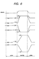
- Fig.6 shows operation waveforms of the substrate bias controlling circuit in another embodiment, all of which are different from those shown in Fig.5.
- the controlling circuit becomes complicated a little more in configuration, but such a complicated controlling circuit enables a larger voltage to be applied to both source and gate terminals of the MP1 and MN2 shown in Fig. 2 respectively in the active state. Both vbp and vbn can thus be driven into a lower impedance.
- the cbp and the cbn equivalent to the gate control signal becomes larger in amplitude than the gate breakdown voltage of the substrate driving transistors MP1 and MN1.
- each circuit block will be assumed as a circuit generating the waveform shown in Fig.4.
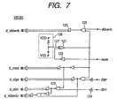
- Fig.7 shows a circuit diagram of the VBC 80.
- Numeral 120 is a 2-input NAND
- 121 is a 2-input AND provided with Schmitt characteristics
- 122 is an inverter
- 123 is a NOR
- 124 is a buffer provided with Schmitt characteristics
- 125 is a buffer provided with a differential output.
- 126 is a power-on resetting circuit, whose output 127 is charged to 1.8V from 0V step by step after the power source VDD is activated. Consequently, the 2-input AND 121 outputs 0V for a fixed time, then outputs 1.8V.
- the d_reset signal is thus asserted by this output for a fixed time as shown in Fig.5 when the power source VDD is activated.
- the power-on resetting circuit 126 shown in Fig.7 is simply composed of resistors and capacitors, the circuit 126 can also be composed in another way if it is possible to detect stabilized power source VDD.
- the signals d_vbbenb, d_cbpr, and d_cbnr are obtained by converting the signals vbbenb, cbpr, and cbnr to dual rail signals respectively. Those dual rail signals are used to activate the substrate controlling when the power-on state is reset.
- the d_vbbenbr which is a dual rail signal used to generate the vbbenbr shown in Fig.5, is generated from cbpr and cbnr.
- Fig. 8 is a circuit diagram of the VBC 30.
- Numeral 130 is a level converting circuit used to generate 3.3V-amplitude signals 133 (VWELL to VSS) from 1.8V-amplitude dual rail signals (VDD to VSS) of both d_vbbenb and d_reset signals.
- a signal 133 enters 'L' in the active state or when the power-on signal is reset.
- Numeral 131 is also a level converting circuit used to generate 3.3V-amplitude signals 134 (VWELL to VSS) from 1. 8V-amplitude dual rail signals (VDD to VSS) of both d_cbpr and d reset signals.
- a signal 134 becomes 0V when the signal cbpr is 0V or when the power-on signal is reset. If a signal 133 becomes 0V in level, the signal vbp enters the high impedance state and both cbp and cbpenbr become 0V. If the signal cbp becomes 0V, the MP1 in every swcell in the main circuit is activated and the signal vbp is driven into 1.8V.
- Numeral 132 is also a level converting circuit used to output the signal d_vbbenbr from the VBC 80 shown in Fig. 7 as a 3.3V-amplitude signal vbbenbr.
- Fig.9 shows how the signal level of cbp is changed.
- the output impedance of the cbp is changed in two steps.
- the cbp is driven by the inverter 135 controlled by a signal 133. If both signals 133 and 134 are 0V, the NMOS 136 is activated, thereby the cbp is driven.
- the gate width of the NMOS 136 is set more wider than that of the NMOS in the inverter 135. If the semiconductor IC unit enters the active state and the signal 133 becomes 0V, then the inverter 135 drives the cbp into 0V.
- the cbp is wired in the whole main circuit and it is provided with a large load capacity, the cbp is driven into 0V slowly. This shift of the cbp is detected according to a shift of the signal cbpr, which is a return signal of the cbp. The signal d_cbpr is thus changed in level. Consequently, the signal 134 is driven into 0V and the NMOS 136 is activated. Consequently, the cbp is driven into 0V at a low impedance. Such way, the cbp is driven at a low impedance in the active state and less affected by anoise caused by an operation of the main circuit.
- the MP1 in every swcell in the main circuit is activated. If the cbp is driven into 0V slowly as shown in Fig.8(B), however, the MP1 in every swcell can be protected significantly from a simultaneous switching noise.
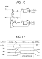
- Fig.10 shows a circuit diagram of the VBC 85.
- 140 is a level converting circuit used to generate 3.3V-amplitude signals 142 (VDD to VSUB) from 1.8V-amplitude dual rail signals (VDD to VSS) of both d_vbbenb and d_reset signals.
- a signal 142 becomes 1.8V in the active state or when the power-on signal is reset.
- 141 is also a level converting circuit used to generate 3.3V-amplitude signals 143 (VDD to VSUB) from 1. 8V-amplitude dual rail signals (VDD to VSS) of both d_cbnr and d_reset signals.
- a signal 143 becomes 1.8V when the signal cbnr is 1.8V or when the power-on signal is reset. If a signal 142 is driven into 1.8V, the signal vbn enters the high impedance state and the signal cbn is driven into 1.8V. If the signal cbn is driven into 1.8V, the MN1 in every swcell in the main circuit is activated. The signal vbn is thus driven into 0V.
- Fig.11 shows how the cbn is shifted.
- the output impedance of the cbn is changed in two steps just like the cbp.
- the cbn is driven by the inverter 144 controlled by the signal 143.
- the PMOS 145 is activated, thereby it is also driven by the PMOS 145.
- the gate width of the PMOS 145 is set larger than the gate width of the PMOS in the inverter 144. If the semiconductor IC unit is shifted into the active state and the signal 142 is driven into 1.8V, the inverter 144 drives the cbn into 0V.
- the cbn is wired in the whole main circuit and its load capacity is large. Therefore, the cbn is driven into 0V slowly. This shift is detected according to a shift of the return signal cbnr of the cbn, thereby the signal d_cbnr is changed in level. This drives the signal 143 into 1.8V and the PMOS 145 is activated. Consequently, the cbn is driven into 1.8V at a low impedance.
- the semiconductor IC unit is active, the cbn is driven at a low impedance just like the cbp, thereby the semiconductor IC unit can be protected effectively from noise caused by the operation of the main circuit.
- the MN1 in every swell in the main circuit is activated. If the cbn is driven into 1.8V slowly as shown in Fig.11, however, the simultaneous switching noise of the MN1 can be reduced in every swell.
- the substrate driving impedance is smaller in the active state in which no bias voltage is applied to each substrate (the substrate is driven by every swell) than in the standby state in which a bias voltage is applied to each substrate (the substrate is driven by VBC). Consequently, if the semiconductor IC unit is shifted into the active state when it is powered as described above, it is possible to avoid problems of an increase of a current, owing to unstableness of the substrate potential, that goes through power sources at a power-on time, as well as a latch-up problem. In addition, although the substrate noise is increased by the operation of the main circuit in the active state, the noise can be reduced thereby preventing the main circuit from problems such as malfunction, latch-up, etc., if the substrate driving impedance is suppressed low.
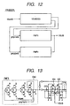
- Fig.12 shows an internal configuration of the negative voltage generating circuit VSUBGEN.
- the circuit is composed of three circuit blocks.
- VSUBSEN is a substrate bias sensing circuit
- PMP1 is a charging pump circuit 1
- PMP2 is a charging pump circuit 2.
- PMP1 is started when the signal pmp1enb is asserted and PMP2 is started when the signal pmp2enb is asserted.
- the pumping capacity makes a difference between PMP1 and PMP2.
- PMP1 has a pumping capacity larger than that of PMP2.
- the signal vbpenb choose to use between PMP1 or PMP2.
- PMP2 is used in the active state and PMP1 is used in the standby state.
- the VSUB potential is used only in the substrate bias controlling circuit when the semiconductor IC unit is in the active state. Thus, so much current does not flows into the VSUB. Consequently, the PMP2, whose pumping capacity is small, is used. In the standby state, the VSUB potential is supplied to the whole main circuit. Such a current as a junction current, etc. thus flows into the VSUB. Consequently, the PMP1, whose pumping capacity is large, is used.
- Fig.13 shows a circuit diagram of the charging pump 1 PMP1 of the present invention.
- OSC is a ring oscillator, which ocillates to charge the VSUB to a negative voltage only when the signal pmplenb is asserted.
- Fig.14 shows a circuit diagram of a charging pump obtained by adding PMOSs 162 and 163 to a charging pump circuit described in "VLSI memory (p266)" written by Kiyoo Ito and published by Baifukan.
- the charging pump charges the VSUB using PMOSs 160 and 162 twice during one cycle oscillation of the ring oscillator.
- NMOSs 164 and 165 are further added to the charging pump as shown in Fig.13. Consequently, the VSUB is less affected by the threshold levels of both PMOSs 160 and 161, so that the VSUB can function satisfactorily even at a low voltage operation.
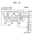
- Fig.15 shows a circuit diagram of the substrate bias sensing circuit VSUBSEN.
- the circuit is composed so that about 1V is applied to between the source and drain of each NMOS transistor, as well as the gate is set long. Consequently, it becomes possible to suppress the continuous current from VDD to VSS or from VWELL to VSUB low.
- the circuit since the circuit is operated in a saturation area, the circuit can obtain VREF or V1 insensitively to a variance. Furthermore, the present invention uses NMOS transistors, not PMOS transistors. NMOS transistors are excellent in saturation characteristics more than PMOS transistors. The circuit can thus obtain VREF or V1 insensitively to a variance among NMOS transistors even when only about 1V is applied to between source and drain.
- AMP1, AMP2, and AMP3 are differential amplifiers, which are combined to compose a differential amplifier.
- the differential amplifier composed of AMP1, AMP2, and AMP3 receives VREF and V1, and when in at VREF ⁇ V1, pmp1enb or pmp2en is asserted. Consequently, VSUB is charged to a negative voltage. When in VREF>V1, pmp1enb or pmp2enb is negated. Since VSUB causes a leakage current toward VSS, VWELL, and VDD, if both pmp1enb and pmp2enb are negated, VSUB is discharged to a positive potential.
- a feed-back path is formed between AMP1 and AMP2.
- the differential amplifier composed of AMP1, AMP2, and AMP3 is thus provided with hysteresis characteristics.
- the operation current of the differential amplifier is changed within AMP1 to AMP3 between when vbpenb is asserted and when it is negated.
- the standby state when vbp is asserted the vbn of the main circuit is connected to the VSUB.
- the level of the VSUB is thus changed slowly. Since no fast operation is needed between AMP1 and AMP3, the operation current can be limited so that the power consumption is reduced in a process from AMP1 to AMP3.
- the active state when the vbp is negated only the substrate bias controlling circuit VBC is connected to the VSUB. This means that a comparatively small capacity is connected to the VSUB.
- Fig. 16 shows a layout of both ncells and swcells.
- the swcells are disposed continuously in the vertical (Y) direction. Both swcells and ncells are aligned in height.
- the swcells are disposed at variable pitches L within a certain value. Of course, those cells can be disposed at equal pitches, but varying the pitches would increase the freedom of the layout. In any way, the pitch L can be decided considering the following items.
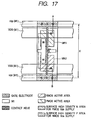
- Fig.17 shows an internal layout of an ncell.
- an inverter is taken as an example.
- the vbp, the vbn, the VDD, and the VSS are powered by the first layer metallic wiring consisting of four lines disposed in parallel (hereafter, to be described as M1).
- the vbp and the vbn are also powered by the surface high density layer respectively.
- H is a cell height, indicating a basic repetition unit in the vertical (Y) direction.
- the ncells are disposed in the vertical (Y) direction so as to be mirror images of each other with reference to this height. Consequently, both vbp and vbn can be shared by ncells adjacent at vertical positions, reducing the ncell area.
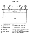
- Fig.18 shows a cross sectional view of Fig.17 at the A-B line.
- N-well is an N-well used for forming MP2 and P-well is a P-well for forming MN2.
- Deep-N is an N-well disposed deeper than N-well and P-well. In other words, the ncell has a 3-layer well structure.
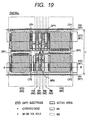
- Fig.19 shows an internal layout of an swcell.
- H is a cell height just as in the case of the ncell.
- the vbp, the vbn, the VDD, and the VSS are powered by M1 in the same way as those of the ncell.
- the swcells are disposed continuously in the vertical (Y) direction. Horizontally, those cells are disposed at pitches restricted within a certain value. With such a disposition, it becomes possible to make wiring of power reinforcing lines at the swcell places.
- the second layer metallic lines disposed in parallel in the vertical direction are two power reinforcing lines.
- the power reinforcing lines VDD and VSS at both ends are effective to protect the four substrate bias control lines from external noise.
- MP1 is formed with 6 separated transistors.
- the gate, drain, and source of each transistor in the MP1 are connected to cbp, vbp, and VDD respectively.
- MN1 is formed with 3 separated transistors.
- the gate, drain, and source of each transistor in the MN1 are connected to cbn, vbn, and VSS respectively.
- Each of the decoupling capacitors CP1 and CP2 is divided into two transistors.
- the transistors of both CP1 and Cp2 are positioned at both ends of the MP1 and MN1 respectively.
- the capacity of each of CP1 and CP2 is generated using a MOS gate capacity.
- the ratio of the decoupling capacitors CP1 and CP2 to those of MP1 and MN1 is not limited specially. In an extreme example, one or both of the decoupling capacitors CP1 and CP2 are omissible. Power noise can be reduced with a decoupling capacitor if its size is increased. On the other hand, if MP1 and MN1 are increased in size, the substrate bias can be connected to a power source at a lower impedance when the microprocessor is in the normal state so as to be protected more effectively from noise, as well as from a latch-up trouble.
- VIA holes formed between the VDD lines of M1 and M2, as well as the VIA holes formed between the VSS lines of M1 and M2 are omitted here to simplify the description.
- a VIA hole can be formed at each intersection point of the wiring.
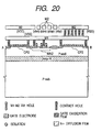
- Fig.20 shows a cross sectional view of Fig.19 at the A-B line.
- P-well is a P-well for forming the MN1
- Deep-N is an N-well disposed deeper than the P-well.
- the swcell thus comes to have a so-called 3-layer well structure.
- VIA holes which are omitted in Fig. 19, are illustrated actually between the VSS lines of both M1 and M2.
- a thick oxidization film transistor is used for MN2 so as to raise the threshold level.
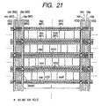
- Fig.21 shows a concrete example for how to wire the power lines VDD and VSS, as well as substrate bias control lines vbp, vbn, cbp, and cbn.
- the layout of power lines shown in Fig.21 is obtained by adding the above lines to the layout shown in Fig.16.
- VDD, VSS, vbp, and vbn are wired with M1 in parallel to each other.
- the vbp is shared by two cells disposed vertically with the vbp therebetween.
- two VDD lines are laid in parallel above and under of those two cells.
- the vbn is also shared by two cells disposed vertically with the vbn therebetween.
- two VSS lines are laid in parallel above and under those two cells.
- both VDD and VSS lines can be thicker than vbp and vbn lines.
- VDD, VSS, vbp, vbn, cbp, and cbn wired with M2 are disposed on the swcells in the vertical (Y) direction.
- VDD, VSS, vbp, and vbn are connected to each other like a mesh at intersection points of M1 and M2.
- Fig.22 shows how power sources VDD and VSS are reinforced.
- the power source lines VDD and VSS formed with the fourth and fifth metallic wiring layers (M4 and M5) are wired like a mesh in accordance with the basic repetition unit shown in Fig.21.
- VDD and VSS formed with M2 which are wired in the vertical (Y) direction, are wired both VDD and VSS formed with M4. And, in order to connect those VDD and VSS to each other, the third metallic wiring layer (M3) is needed. If those VDD and VSS are connected at every swcell, the M3 is wired vertically. This will arise a problem that no M3 path is formed in the horizontal (X) direction, however.
- M2 and M4 power lines are connected every three swcells shown as swcell2 or swcell3. With this connection, M3 wiring paths can be secured in the horizontal (X) direction.
- the M5 power line is wired only on every 6 swcells shown as swcell3.
- the M5 power line is thus connected to the M4 line at each swcell3, which is an intersection point of M5 and M4.
- the fine pitch power source meshes of M1 and M2 are reinforced by the rough pitch power source meshes of M4 and M5, thereby to lower the impedance of each of the VDD and VSS power source lines.
- each of the M4 power source lines in the vertical direction is wired at every swcell, the line may also be wired roughly every two or three swcells. Although the impedance of each of the power source lines increases, this wiring method makes it possible to secure M4 paths in the vertical direction.
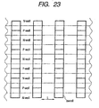
- Fig.23 shows the relationship between swcells and wells disposed as shown in Fig. 22.
- P-wells and N-wells are disposed alternately like belts so that two ncells share one well.
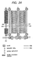
- Fig.24 shows a layout of both memory circuit swcells and power source lines.
- word lines are disposed actually in the horizontal (X) direction and bit lines are disposed actually in the vertical (Y) direction respectively.
- the memory mat power source lines wired horizontally in the memory cells are reinforced by the power lines 200, 201, and 202 provided at both ends thereof.
- Numeral 203 is a power line for supplying an electric power to each of word drivers and decoders.
- 204 is a power line for supplying an electric power to each sense amplifier.
- Cells swcell are disposed for each of the power lines 200 to 204 as shown in Fig.24.
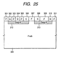
- Fig.25 shows a cross sectional view of a semiconductor IC unit of the present invention.
- the Ns shown as 302, 304, 306, 308, and 310 are the same as an N-well respectively used to form a PMOS transistor.
- the Ps shown as 301, 303, 305, 307, 309, and 311 are the same as a P-well respectively used to form an NMOS transistor.
- the Deep-Ns shown as 312 and 313 are N-wells formed at deeper positions than Ns and Ps.
- the semiconductor IC unit has a "triple well structure".
- the Deep-Ns 312 and 313 are separated electrically by a p-substrate 310 and a P-well 307. Consequently, the substrate potential of the MOS transistors A formed on 302, 304, 306, 308, and 310 can be decided independently of the substrate potential of the MOS transistors B formed on 301, 303, 305, 307, 309, and 311, and vice versa. In addition, the noise, etc. generated from the MOS transistors A can be suppressed so as to effectively protect the MOS transistors B from its influence.
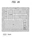
- Fig.26 shows the Deep-N structure of the semiconductor IC unit of the present invention.
- CPG is a clock controller and it includes analog circuits such as a PLL (Phase Locked Loop), etc.
- TLB is an address converter and CACHE is a cache memory.
- CPU is a central processing unit
- FPU is a floating-point arithmetic unit
- LOG1 is a random logic 1
- LOG2 is a random logic 2
- PAD is an I/O unit.
- Each circuit block is formed such way on a Deep-N different from others.
- Fig.27 shows a guard band disposed between Deep-Ns.
- a guard band gband1 is thus disposed between the Deep-Ns as shown in Fig.27.
- Fig. 28 shows a cross sectional view of the guard band shown in Fig.27.
- a P-well 307 provided between Deep-Ns is then grounded to the VSS potential through the P+ diffusion layer 314. This makes it possible to further reduce the transmission of a noise between the Deep-Ns.
- the substrate noise generated in a MOS transistor on the P-well 305 is transmitted to the Deep-N 312 due to a capacitive coupling, since the impedance of the Deep-N 312 is not so low.
- the p-substrate is fixed to the ground potential by a guard band at a low impedance.
- the noise, when appearing on the p-substrate, is thus reduced. Such way, it is suppressed effectively for the noise generated from the MOS transistors formed on 302, 304, 306, 308, and 310 to be transmitted to the MOS transistors formed on 301, 303, 305, 307, 309, and 311.
- Fig.29 shows layout images of both cbp and cbpr on a semiconductor IC unit and the position of the return cell VBCR shown in Fig.2.
- the description of both cbn and cbnr will be omitted here, since it is the same as that of both cbp and cbpr.
- the vbp and the vbn are wired like a mesh, since swcells are disposed side by side as shown in Fig.21. However, the cbp and the cbn are not wired like a mesh; they are wired like stripes.
- Fig.29 shows swcells disposed and connected so as to shunt the stripe-like wiring.
- a return cell is used to return entered cbp and cbn to the substrate bias controlling circuit VBC as cbpr and cbnr.
- a return cell is thus disposed so that cbpr is returned at a later timing than the arrival of the cbp of the swcell whose transmission time for cbpr is the latest among the swcells.
- such a return cell should be disposed farthest from the substrate bias controlling circuit VBC.
- the potential to be applied to the substrate bias is 1.8V or 0.0V in the active state and 3. 3V or -1.5V in the standby state.
- the potential value can be varied freely.
- a proper potential can be applied to the substrate bias thereby to adjust the variance of the threshold level of the MOS transistors.
- the main circuit can also be divided into a plurality of circuit blocks, so that each of those circuit blocks is provided with a controlling circuit such as VBC 30, VBC 85, etc., thereby each circuit block is provided with active and standby states.
- Each circuit block can thus be controlled so that other idle circuit blocks are set in the standby state. Consequently, power consumption can be controlled for the semiconductor IC unit of the present invention more effectively in detail.
- the threshold level of the MOS transistors is set low in the active operation mode and high in the standby operation mode of the semiconductor IC unit respectively.
- the bias voltage to be spplied to the substrate can be set so that a high threshold level is assumed for an IDDQ test as described in 1996 IEEE SPECTRUM (pp.66-71).
- the substrate should be applied a larger substrate potential for an IDDQ test than the substrate potential applied in the standby mode.
- PMOSFET should be applied a higher potential than that in the standby mode
- NMOSFET should be applied a lower potential than that in the standby mode. This enables to reduce the subthreshold leakage current that flows at an IDDQ test, improving the accuracy of trouble locating.
- the VWELL potential is increased, for example, from 3.3V to 4.0V and the VSUB potential is lowered from -1.5V to -2.2V for an IDDQ test.
- a proper measure should be taken to prevent a through-current from flowing in an object circuit even the VWELL potential is set differently from the VDDQ potential.
- all the signals to be transmitted to the substrate bias controlling circuit must be level-downed in the VBC 80, then their potential must be converted to the VWELL or VSUM potential before use.
- the obj ect circuit should be provided with a buffer used for such a voltage to realize the above operation
- the substrate structure is composed of 3 well layers.
- the structure can be varied, for example, to a so-called twin-tab 2-well structure or an SOI (Silicon on insulator) structure.
- M1 supplies a substrate bias power in cells.
- This structure can be varied, however.
- such a power can also be supplied from a diffusion layer or a silicide-transformed diffusion layer as described in 1997 Symposium on VLSI circuits Digest of Technical Papers, pp.95-96.
- VBC Substrate bias controlling circuit
- LOG Main circuit
- VBCC Stand-by controlling circuit
- I/O I/O circuit
- vbbenb Substrate bias controlling start signal
- vbbenbr Substrate bias controlling-now signal
- vbp PMOS substrate bias line
- vbn NMOS substrate bias line
- cbp PMOS substrate controlling line
- cbn NMOS substrate controlling line
- cbpr PMOS substrate control return line
- cbnr NMOS substrate control return line
- AMP1 and AMP2 Differential amplifier
- AMP3 Schmitt input differential amplifier
- VBCR Return cell
- swcell Switch cell
- ncell Standard cell
- P-sub P-substrate
- PLL Phase locked loop
- CPG Clock controller
- TLB Address transformer
- CHCHE Address transformer
- CHCHE Address transformer
- CHCHE Address transformer
- CHCHE Address transformer
- CHCHE Address transformer
- CHCHE Address transformer
- the present invention can provide a semiconductor IC unit, such as a microprocessor, etc., which can satisfy the following requirements with respect to fast operation and lower power consumption properties:
Applications Claiming Priority (3)
| Application Number | Priority Date | Filing Date | Title |
|---|---|---|---|
| JP35927197A JP4109340B2 (ja) | 1997-12-26 | 1997-12-26 | 半導体集積回路装置 |
| JP35927197 | 1997-12-26 | ||
| PCT/JP1998/005770 WO1999034445A1 (en) | 1997-12-26 | 1998-12-21 | Semiconductor integrated circuit |
Publications (3)
| Publication Number | Publication Date |
|---|---|
| EP1043774A1 EP1043774A1 (en) | 2000-10-11 |
| EP1043774A4 EP1043774A4 (en) | 2002-01-02 |
| EP1043774B1 true EP1043774B1 (en) | 2004-07-07 |
Family
ID=18463648
Family Applications (1)
| Application Number | Title | Priority Date | Filing Date |
|---|---|---|---|
| EP98961441A Expired - Lifetime EP1043774B1 (en) | 1997-12-26 | 1998-12-21 | Semiconductor integrated circuit |
Country Status (9)
| Country | Link |
|---|---|
| US (8) | US6483374B1 (ja) |
| EP (1) | EP1043774B1 (ja) |
| JP (1) | JP4109340B2 (ja) |
| KR (1) | KR100625153B1 (ja) |
| CN (1) | CN1195324C (ja) |
| DE (1) | DE69824972T2 (ja) |
| MY (1) | MY118314A (ja) |
| TW (1) | TW426988B (ja) |
| WO (1) | WO1999034445A1 (ja) |
Families Citing this family (84)
| Publication number | Priority date | Publication date | Assignee | Title |
|---|---|---|---|---|
| JP4109340B2 (ja) * | 1997-12-26 | 2008-07-02 | 株式会社ルネサステクノロジ | 半導体集積回路装置 |
| TW453032B (en) * | 1998-09-09 | 2001-09-01 | Hitachi Ltd | Semiconductor integrated circuit apparatus |
| JP2009123235A (ja) * | 2000-06-16 | 2009-06-04 | Renesas Technology Corp | 半導体集積回路装置 |
| JPWO2002029893A1 (ja) * | 2000-10-03 | 2004-02-19 | 株式会社ルネサステクノロジ | 半導体装置 |
| JP2002313937A (ja) * | 2001-04-16 | 2002-10-25 | Sony Corp | 集積回路装置 |
| US7112978B1 (en) | 2002-04-16 | 2006-09-26 | Transmeta Corporation | Frequency specific closed loop feedback control of integrated circuits |
| US7941675B2 (en) * | 2002-12-31 | 2011-05-10 | Burr James B | Adaptive power control |
| US6734472B2 (en) | 2002-04-25 | 2004-05-11 | Synplicity, Inc. | Power and ground shield mesh to remove both capacitive and inductive signal coupling effects of routing in integrated circuit device |
| JP4401621B2 (ja) * | 2002-05-07 | 2010-01-20 | 株式会社日立製作所 | 半導体集積回路装置 |
| US6933744B2 (en) * | 2002-06-11 | 2005-08-23 | The Regents Of The University Of Michigan | Low-leakage integrated circuits and dynamic logic circuits |
| US6864539B2 (en) * | 2002-07-19 | 2005-03-08 | Semiconductor Technology Academic Research Center | Semiconductor integrated circuit device having body biasing circuit for generating forward well bias voltage of suitable level by using simple circuitry |
| US7739624B2 (en) | 2002-07-29 | 2010-06-15 | Synopsys, Inc. | Methods and apparatuses to generate a shielding mesh for integrated circuit devices |
| US7943436B2 (en) | 2002-07-29 | 2011-05-17 | Synopsys, Inc. | Integrated circuit devices and methods and apparatuses for designing integrated circuit devices |
| JP2004152975A (ja) * | 2002-10-30 | 2004-05-27 | Renesas Technology Corp | 半導体装置の製造方法および半導体装置 |
| US7053692B2 (en) * | 2002-12-19 | 2006-05-30 | United Memories, Inc. | Powergate control using boosted and negative voltages |
| US7228242B2 (en) | 2002-12-31 | 2007-06-05 | Transmeta Corporation | Adaptive power control based on pre package characterization of integrated circuits |
| US7953990B2 (en) | 2002-12-31 | 2011-05-31 | Stewart Thomas E | Adaptive power control based on post package characterization of integrated circuits |
| JP4708716B2 (ja) * | 2003-02-27 | 2011-06-22 | ルネサスエレクトロニクス株式会社 | 半導体集積回路装置、半導体集積回路装置の設計方法 |
| JP4342833B2 (ja) | 2003-05-16 | 2009-10-14 | Necエレクトロニクス株式会社 | 容量セルと半導体装置及びその製造方法 |
| US7219324B1 (en) * | 2003-06-02 | 2007-05-15 | Virage Logic Corporation | Various methods and apparatuses to route multiple power rails to a cell |
| US7250807B1 (en) * | 2003-06-05 | 2007-07-31 | National Semiconductor Corporation | Threshold scaling circuit that minimizes leakage current |
| JP2005109179A (ja) * | 2003-09-30 | 2005-04-21 | National Institute Of Advanced Industrial & Technology | 高速低消費電力論理装置 |
| US7649402B1 (en) | 2003-12-23 | 2010-01-19 | Tien-Min Chen | Feedback-controlled body-bias voltage source |
| US7692477B1 (en) | 2003-12-23 | 2010-04-06 | Tien-Min Chen | Precise control component for a substrate potential regulation circuit |
| US7012461B1 (en) | 2003-12-23 | 2006-03-14 | Transmeta Corporation | Stabilization component for a substrate potential regulation circuit |
| US7129771B1 (en) * | 2003-12-23 | 2006-10-31 | Transmeta Corporation | Servo loop for well bias voltage source |
| US7026843B1 (en) * | 2004-01-16 | 2006-04-11 | Spansion Llc | Flexible cascode amplifier circuit with high gain for flash memory cells |
| US7033883B2 (en) * | 2004-06-04 | 2006-04-25 | Faraday Technology Corp. | Placement method for decoupling capacitors |
| CN101006644B (zh) * | 2004-06-15 | 2010-08-25 | Nxp股份有限公司 | 用于集成电路的电源的自适应控制 |
| US7774625B1 (en) | 2004-06-22 | 2010-08-10 | Eric Chien-Li Sheng | Adaptive voltage control by accessing information stored within and specific to a microprocessor |
| US7562233B1 (en) | 2004-06-22 | 2009-07-14 | Transmeta Corporation | Adaptive control of operating and body bias voltages |
| US7319357B2 (en) * | 2004-08-24 | 2008-01-15 | Texas Instruments Incorporated | System for controlling switch transistor performance |
| JP2006173492A (ja) * | 2004-12-17 | 2006-06-29 | Matsushita Electric Ind Co Ltd | 半導体装置 |
| JP2006217540A (ja) * | 2005-02-07 | 2006-08-17 | Fujitsu Ltd | 半導体集積回路および半導体集積回路の制御方法 |
| EP1882307B1 (en) * | 2005-05-13 | 2013-07-31 | MOSAID Technologies Incorporated | Integrated circuit with sleep signal bus formed by cell abutment of logic cells |
| JP2007027314A (ja) * | 2005-07-14 | 2007-02-01 | Nec Electronics Corp | 半導体集積回路装置 |
| JP2007148952A (ja) * | 2005-11-30 | 2007-06-14 | Renesas Technology Corp | 半導体集積回路 |
| US20070152745A1 (en) * | 2005-12-30 | 2007-07-05 | Taiwan Semiconductor Manufacturing Co., Ltd. | System and method for reducing leakage current of an integrated circuit |
| JP2007201236A (ja) * | 2006-01-27 | 2007-08-09 | Renesas Technology Corp | 半導体集積回路 |
| JP5092263B2 (ja) * | 2006-03-31 | 2012-12-05 | 富士通セミコンダクター株式会社 | デカップリングコンデンサ及び半導体集積回路装置 |
| JP2008103569A (ja) * | 2006-10-19 | 2008-05-01 | Nec Electronics Corp | 半導体装置 |
| US7989849B2 (en) * | 2006-11-15 | 2011-08-02 | Synopsys, Inc. | Apparatuses and methods for efficient power rail structures for cell libraries |
| US7532078B2 (en) * | 2007-02-09 | 2009-05-12 | International Business Machines Corporation | Scannable virtual rail method and ring oscillator circuit for measuring variations in device characteristics |
| JP2008205271A (ja) * | 2007-02-21 | 2008-09-04 | Matsushita Electric Ind Co Ltd | 半導体保護回路およびその製造方法、半導体保護回路の動作方法 |
| JP5307427B2 (ja) * | 2007-04-05 | 2013-10-02 | ルネサスエレクトロニクス株式会社 | 半導体装置 |
| CN101689150B (zh) | 2007-06-20 | 2011-11-30 | 富士通株式会社 | 信息处理装置及控制方法 |
| JP5142686B2 (ja) * | 2007-11-30 | 2013-02-13 | ルネサスエレクトロニクス株式会社 | 半導体集積回路 |
| US8189376B2 (en) * | 2008-02-08 | 2012-05-29 | Micron Technology, Inc. | Integrated circuit having memory cells including gate material having high work function, and method of manufacturing same |
| US7880533B2 (en) * | 2008-03-25 | 2011-02-01 | Analog Devices, Inc. | Bandgap voltage reference circuit |
| US7683697B2 (en) * | 2008-05-30 | 2010-03-23 | Freescale Semiconductor, Inc. | Circuitry and method for buffering a power mode control signal |
| EP2319043B1 (en) * | 2008-07-21 | 2018-08-15 | Sato Holdings Corporation | A device having data storage |
| JP5486172B2 (ja) | 2008-08-07 | 2014-05-07 | ルネサスエレクトロニクス株式会社 | 半導体記憶装置 |
| US7812662B2 (en) * | 2008-10-07 | 2010-10-12 | Via Technologies, Inc. | System and method for adjusting supply voltage levels to reduce sub-threshold leakage |
| KR101211683B1 (ko) * | 2008-12-31 | 2012-12-12 | 에스케이하이닉스 주식회사 | 반도체 집적회로 |
| JP2010283269A (ja) * | 2009-06-08 | 2010-12-16 | Renesas Electronics Corp | 半導体装置 |
| JP5529450B2 (ja) * | 2009-07-15 | 2014-06-25 | スパンション エルエルシー | ボディバイアス制御回路及びボディバイアス制御方法 |
| US8385036B2 (en) * | 2009-10-07 | 2013-02-26 | Intersil Americas Inc. | System and method for negative voltage protection |
| KR101046275B1 (ko) * | 2010-03-29 | 2011-07-04 | 주식회사 하이닉스반도체 | 파워 메쉬 구조를 갖는 반도체 메모리 장치 |
| JP5540910B2 (ja) * | 2010-06-08 | 2014-07-02 | 富士通セミコンダクター株式会社 | 集積回路、集積回路設計装置及び集積回路設計方法 |
| DE112011102644B4 (de) * | 2010-08-06 | 2019-12-05 | Semiconductor Energy Laboratory Co., Ltd. | Integrierte Halbleiterschaltung |
| JP5614333B2 (ja) * | 2011-03-01 | 2014-10-29 | 富士通セミコンダクター株式会社 | 半導体装置 |
| CN102215007B (zh) * | 2011-05-27 | 2013-11-20 | 唐险峰 | 功率控制电路板 |
| JP5782919B2 (ja) * | 2011-08-25 | 2015-09-24 | サンケン電気株式会社 | 半導体装置 |
| US8810283B2 (en) * | 2012-05-22 | 2014-08-19 | Analog Devices, Inc. | CMOS transistor linearization method |
| KR102100708B1 (ko) * | 2013-08-30 | 2020-04-16 | 에스케이하이닉스 주식회사 | 반도체 메모리 장치 |
| KR102136228B1 (ko) * | 2013-12-13 | 2020-07-21 | 에스케이하이닉스 주식회사 | 차동 시그널링을 지원하는 송/수신기 및 이를 포함하는 반도체 송/수신 시스템 |
| US9557755B2 (en) * | 2014-06-13 | 2017-01-31 | Gn Resound A/S | Interface circuit for a hearing aid and method |
| JP5866415B2 (ja) * | 2014-06-30 | 2016-02-17 | ルネサスエレクトロニクス株式会社 | 半導体集積回路装置 |
| US9842182B2 (en) | 2014-10-01 | 2017-12-12 | Samsung Electronics Co., Ltd. | Method and system for designing semiconductor device |
| JP2016092536A (ja) * | 2014-10-31 | 2016-05-23 | ルネサスエレクトロニクス株式会社 | 半導体装置 |
| KR20170044411A (ko) * | 2015-10-15 | 2017-04-25 | 에스케이하이닉스 주식회사 | 반도체장치 |
| US10250247B2 (en) | 2016-02-10 | 2019-04-02 | Semiconductor Energy Laboratory Co., Ltd. | Semiconductor device, electronic component, and electronic device |
| US10236875B2 (en) | 2016-04-15 | 2019-03-19 | Semiconductor Energy Laboratory Co., Ltd. | Semiconductor device and method for operating the semiconductor device |
| MX2019000912A (es) | 2016-07-22 | 2019-09-27 | Nantenergy Inc | Sistema de gestion de humedad y dioxido de carbono de celdas electroquimicas. |
| DE102016125404A1 (de) * | 2016-12-15 | 2018-06-21 | Taiwan Semiconductor Manufacturing Co. Ltd. | Dual-rail-speicher, speichermakro und zugehöriges hybrides stromversorgungsverfahren |
| US10944396B2 (en) | 2017-03-03 | 2021-03-09 | Semiconductor Energy Laboratory Co., Ltd. | Semiconductor device and method for driving the semiconductor device |
| KR102542173B1 (ko) | 2017-05-31 | 2023-06-09 | 가부시키가이샤 한도오따이 에네루기 켄큐쇼 | 비교 회로, 반도체 장치, 전자 부품, 및 전자 기기 |
| WO2018233833A1 (en) | 2017-06-22 | 2018-12-27 | Abb Schweiz Ag | METHOD OF OPERATING AN ELECTRIC ARC OVEN, ELECTRONIC POWER CONVERTER, AND ELECTRIC ARC OVEN SYSTEM |
| JP7228389B2 (ja) | 2019-01-23 | 2023-02-24 | ルネサスエレクトロニクス株式会社 | 半導体装置および半導体システム |
| EP3966887A1 (en) | 2019-05-10 | 2022-03-16 | NantEnergy, Inc. | Nested annular metal-air cell and systems containing same |
| US11139017B2 (en) * | 2019-11-12 | 2021-10-05 | Taiwan Semiconductor Manufacturing Company, Ltd. | Self-activated bias generator |
| US11567551B2 (en) | 2020-07-28 | 2023-01-31 | Rohde & Schwarz Gmbh & Co. Kg | Adaptive power supply |
| CN115497521B (zh) * | 2022-11-08 | 2023-02-17 | 长鑫存储技术有限公司 | 一种供电电路、存储器和电子设备 |
| CN116027842B (zh) * | 2023-03-24 | 2023-06-23 | 长鑫存储技术有限公司 | 功率控制电路、存储器及电子设备 |
Family Cites Families (36)
| Publication number | Priority date | Publication date | Assignee | Title |
|---|---|---|---|---|
| JPS6020550A (ja) * | 1983-07-15 | 1985-02-01 | Hitachi Ltd | 半導体集積回路装置 |
| US4628215A (en) * | 1984-09-17 | 1986-12-09 | Texas Instruments Incorporated | Drive circuit for substrate pump |
| JPH0198254A (ja) * | 1987-10-09 | 1989-04-17 | Nec Corp | Mos型半導体装置 |
| JP2552534B2 (ja) * | 1988-06-17 | 1996-11-13 | 三洋電機株式会社 | 基板バイアス電圧発生回路 |
| JPH02154446A (ja) * | 1988-12-06 | 1990-06-13 | Matsushita Electron Corp | 半導体装置の自動設計方法 |
| JP2841917B2 (ja) * | 1991-05-23 | 1998-12-24 | 松下電器産業株式会社 | 基板電位発生回路 |
| JP2805991B2 (ja) * | 1990-06-25 | 1998-09-30 | ソニー株式会社 | 基板バイアス発生回路 |
| JPH04345059A (ja) | 1991-05-22 | 1992-12-01 | Toshiba Corp | 面実装型半導体部品 |
| JPH05190670A (ja) | 1992-01-16 | 1993-07-30 | Toshiba Corp | 半導体集積回路装置 |
| JPH05190672A (ja) * | 1992-01-17 | 1993-07-30 | Hitachi Ltd | 半導体装置及びそのレイアウト方式 |
| JP3253389B2 (ja) * | 1992-03-31 | 2002-02-04 | 株式会社東芝 | 半導体集積回路装置 |
| US5461338A (en) * | 1992-04-17 | 1995-10-24 | Nec Corporation | Semiconductor integrated circuit incorporated with substrate bias control circuit |
| JP3503961B2 (ja) | 1992-06-02 | 2004-03-08 | 株式会社東芝 | 半導体装置 |
| JPH076581A (ja) * | 1992-11-10 | 1995-01-10 | Texas Instr Inc <Ti> | 基板バイアス・ポンプ装置 |
| US5811990A (en) * | 1993-10-15 | 1998-09-22 | Micron Technology, Inc. | Voltage pump and a level translator circuit |
| KR0169157B1 (ko) * | 1993-11-29 | 1999-02-01 | 기다오까 다까시 | 반도체 회로 및 mos-dram |
| JPH07254685A (ja) | 1994-03-16 | 1995-10-03 | Toshiba Corp | 半導体記憶装置 |
| JP2822881B2 (ja) * | 1994-03-30 | 1998-11-11 | 日本電気株式会社 | 半導体集積回路装置 |
| JP3645593B2 (ja) * | 1994-09-09 | 2005-05-11 | 株式会社ルネサステクノロジ | 半導体集積回路装置 |
| JP3175521B2 (ja) | 1995-01-27 | 2001-06-11 | 日本電気株式会社 | シリコン・オン・インシュレータ半導体装置及びバイアス電圧発生回路 |
| JPH08249882A (ja) * | 1995-03-15 | 1996-09-27 | Nec Corp | 半導体集積回路 |
| US6259310B1 (en) * | 1995-05-23 | 2001-07-10 | Texas Instruments Incorporated | Apparatus and method for a variable negative substrate bias generator |
| DE69530773D1 (de) * | 1995-10-30 | 2003-06-18 | St Microelectronics Srl | Interface-Schaltung zum Steuern von elektronischen Schaltern mit Signalen erhöhter Spannung |
| EP0772282B1 (en) * | 1995-10-31 | 2000-03-15 | STMicroelectronics S.r.l. | Negative charge pump circuit for electrically erasable semiconductor memory devices |
| KR970028938A (ko) * | 1995-11-28 | 1997-06-26 | 김광호 | 외부 리셋 회로를 구비한 모뎀 장치 |
| JPH09293789A (ja) * | 1996-04-24 | 1997-11-11 | Mitsubishi Electric Corp | 半導体集積回路 |
| KR100223770B1 (ko) * | 1996-06-29 | 1999-10-15 | 김영환 | 반도체 장치의 문턱전압 제어회로 |
| US5786724A (en) * | 1996-12-17 | 1998-07-28 | Texas Instruments Incorporated | Control of body effect in MOS transistors by switching source-to-body bias |
| JP3732914B2 (ja) * | 1997-02-28 | 2006-01-11 | 株式会社ルネサステクノロジ | 半導体装置 |
| KR100273208B1 (ko) * | 1997-04-02 | 2000-12-15 | 김영환 | 반도체메모리장치의고효율전하펌프회로 |
| JP3814385B2 (ja) * | 1997-10-14 | 2006-08-30 | 株式会社ルネサステクノロジ | 半導体集積回路装置 |
| JP4109340B2 (ja) * | 1997-12-26 | 2008-07-02 | 株式会社ルネサステクノロジ | 半導体集積回路装置 |
| US6191615B1 (en) * | 1998-03-30 | 2001-02-20 | Nec Corporation | Logic circuit having reduced power consumption |
| JP4390304B2 (ja) * | 1998-05-26 | 2009-12-24 | 株式会社ルネサステクノロジ | 半導体集積回路装置 |
| TW453032B (en) * | 1998-09-09 | 2001-09-01 | Hitachi Ltd | Semiconductor integrated circuit apparatus |
| US6198340B1 (en) * | 1999-02-08 | 2001-03-06 | Etron Technology, Inc. | High efficiency CMOS pump circuit |
-
1997
- 1997-12-26 JP JP35927197A patent/JP4109340B2/ja not_active Expired - Lifetime
-
1998
- 1998-12-09 TW TW087120452A patent/TW426988B/zh not_active IP Right Cessation
- 1998-12-19 MY MYPI98005761A patent/MY118314A/en unknown
- 1998-12-21 CN CNB988126702A patent/CN1195324C/zh not_active Expired - Fee Related
- 1998-12-21 US US09/582,485 patent/US6483374B1/en not_active Expired - Lifetime
- 1998-12-21 WO PCT/JP1998/005770 patent/WO1999034445A1/ja active IP Right Grant
- 1998-12-21 KR KR1020007007127A patent/KR100625153B1/ko not_active IP Right Cessation
- 1998-12-21 DE DE69824972T patent/DE69824972T2/de not_active Expired - Lifetime
- 1998-12-21 EP EP98961441A patent/EP1043774B1/en not_active Expired - Lifetime
-
2000
- 2000-01-27 US US09/492,506 patent/US6337593B1/en not_active Expired - Lifetime
-
2002
- 2002-09-20 US US10/247,525 patent/US6600360B2/en not_active Expired - Lifetime
-
2003
- 2003-05-22 US US10/443,018 patent/US6707334B2/en not_active Expired - Lifetime
-
2004
- 2004-01-29 US US10/765,923 patent/US6987415B2/en not_active Expired - Lifetime
-
2005
- 2005-06-06 US US11/144,695 patent/US7046075B2/en not_active Expired - Lifetime
-
2006
- 2006-04-04 US US11/396,543 patent/US7321252B2/en not_active Expired - Fee Related
-
2007
- 2007-11-27 US US11/987,073 patent/US7598796B2/en not_active Expired - Fee Related
Also Published As
| Publication number | Publication date |
|---|---|
| US7598796B2 (en) | 2009-10-06 |
| DE69824972D1 (de) | 2004-08-12 |
| US20080136502A1 (en) | 2008-06-12 |
| KR20010033614A (ko) | 2001-04-25 |
| US6987415B2 (en) | 2006-01-17 |
| US6707334B2 (en) | 2004-03-16 |
| US6600360B2 (en) | 2003-07-29 |
| US6483374B1 (en) | 2002-11-19 |
| JPH11191611A (ja) | 1999-07-13 |
| US20060176101A1 (en) | 2006-08-10 |
| US7321252B2 (en) | 2008-01-22 |
| EP1043774A1 (en) | 2000-10-11 |
| US20040183585A1 (en) | 2004-09-23 |
| KR100625153B1 (ko) | 2006-09-20 |
| US20050218965A1 (en) | 2005-10-06 |
| JP4109340B2 (ja) | 2008-07-02 |
| DE69824972T2 (de) | 2005-07-14 |
| CN1283308A (zh) | 2001-02-07 |
| US7046075B2 (en) | 2006-05-16 |
| US20030206049A1 (en) | 2003-11-06 |
| MY118314A (en) | 2004-09-30 |
| US20030016076A1 (en) | 2003-01-23 |
| TW426988B (en) | 2001-03-21 |
| US6337593B1 (en) | 2002-01-08 |
| WO1999034445A1 (en) | 1999-07-08 |
| CN1195324C (zh) | 2005-03-30 |
| EP1043774A4 (en) | 2002-01-02 |
Similar Documents
| Publication | Publication Date | Title |
|---|---|---|
| EP1043774B1 (en) | Semiconductor integrated circuit | |
| US7514766B2 (en) | Semiconductor device | |
| JP3928837B2 (ja) | 半導体集積回路装置 | |
| US6046627A (en) | Semiconductor device capable of operating stably with reduced power consumption | |
| JP4401621B2 (ja) | 半導体集積回路装置 | |
| US20160365358A1 (en) | Semiconductor integrated circuit device | |
| Kim et al. | A multi-mode power gating structure for low-voltage deep-submicron CMOS ICs | |
| JP3990352B2 (ja) | 半導体集積回路装置 | |
| US5625280A (en) | Voltage regulator bypass circuit | |
| EP1012971A1 (en) | Forward body bias transistor circuits | |
| JP4803756B2 (ja) | 半導体集積回路装置 | |
| JP4106033B2 (ja) | 半導体集積回路装置 | |
| US7529071B2 (en) | Circuit for selectively bypassing a capacitive element | |
| US7589562B2 (en) | I/O cell capable of finely controlling drive strength | |
| US7248092B2 (en) | Clamp circuit device | |
| JP2007060722A (ja) | 半導体集積回路装置 | |
| KR100328446B1 (ko) | 플래쉬 메모리 소자의 정전기 방전 회로 | |
| JP2001060628A (ja) | 半導体集積回路装置 | |
| JP2004363842A (ja) | 半導体集積回路 |
Legal Events
| Date | Code | Title | Description |
|---|---|---|---|
| PUAI | Public reference made under article 153(3) epc to a published international application that has entered the european phase |
Free format text: ORIGINAL CODE: 0009012 |
|
| 17P | Request for examination filed |
Effective date: 20000717 |
|
| AK | Designated contracting states |
Kind code of ref document: A1 Designated state(s): DE FR GB IT |
|
| A4 | Supplementary search report drawn up and despatched |
Effective date: 20011108 |
|
| AK | Designated contracting states |
Kind code of ref document: A4 Designated state(s): DE FR GB IT |
|
| RIC1 | Information provided on ipc code assigned before grant |
Free format text: 7G 11C 5/14 A, 7G 11C 11/34 B, 7H 01L 27/04 B, 7G 11C 11/407 B |
|
| 17Q | First examination report despatched |
Effective date: 20020131 |
|
| GRAP | Despatch of communication of intention to grant a patent |
Free format text: ORIGINAL CODE: EPIDOSNIGR1 |
|
| GRAS | Grant fee paid |
Free format text: ORIGINAL CODE: EPIDOSNIGR3 |
|
| GRAA | (expected) grant |
Free format text: ORIGINAL CODE: 0009210 |
|
| AK | Designated contracting states |
Kind code of ref document: B1 Designated state(s): DE FR GB IT |
|
| PG25 | Lapsed in a contracting state [announced via postgrant information from national office to epo] |
Ref country code: IT Free format text: LAPSE BECAUSE OF FAILURE TO SUBMIT A TRANSLATION OF THE DESCRIPTION OR TO PAY THE FEE WITHIN THE PRESCRIBED TIME-LIMIT;WARNING: LAPSES OF ITALIAN PATENTS WITH EFFECTIVE DATE BEFORE 2007 MAY HAVE OCCURRED AT ANY TIME BEFORE 2007. THE CORRECT EFFECTIVE DATE MAY BE DIFFERENT FROM THE ONE RECORDED. Effective date: 20040707 |
|
| REG | Reference to a national code |
Ref country code: GB Ref legal event code: FG4D |
|
| REF | Corresponds to: |
Ref document number: 69824972 Country of ref document: DE Date of ref document: 20040812 Kind code of ref document: P |
|
| ET | Fr: translation filed | ||
| PLBE | No opposition filed within time limit |
Free format text: ORIGINAL CODE: 0009261 |
|
| STAA | Information on the status of an ep patent application or granted ep patent |
Free format text: STATUS: NO OPPOSITION FILED WITHIN TIME LIMIT |
|
| 26N | No opposition filed |
Effective date: 20050408 |
|
| REG | Reference to a national code |
Ref country code: FR Ref legal event code: TP |
|
| REG | Reference to a national code |
Ref country code: FR Ref legal event code: TP Owner name: RENESAS ELECTRONICS CORPORATION, JP Effective date: 20140324 Ref country code: FR Ref legal event code: CD Owner name: RENESAS ELECTRONICS CORPORATION, JP Effective date: 20140324 |
|
| REG | Reference to a national code |
Ref country code: DE Ref legal event code: R082 Ref document number: 69824972 Country of ref document: DE Representative=s name: BEETZ & PARTNER PATENT- UND RECHTSANWAELTE, DE |
|
| REG | Reference to a national code |
Ref country code: DE Ref legal event code: R082 Ref document number: 69824972 Country of ref document: DE Representative=s name: BEETZ & PARTNER MBB PATENT- UND RECHTSANWAELTE, DE Effective date: 20140911 Ref country code: DE Ref legal event code: R082 Ref document number: 69824972 Country of ref document: DE Representative=s name: BEETZ & PARTNER MBB PATENTANWAELTE, DE Effective date: 20140911 Ref country code: DE Ref legal event code: R082 Ref document number: 69824972 Country of ref document: DE Representative=s name: BEETZ & PARTNER PATENT- UND RECHTSANWAELTE, DE Effective date: 20140911 Ref country code: DE Ref legal event code: R081 Ref document number: 69824972 Country of ref document: DE Owner name: RENESAS ELECTRONICS CORPORATION, KAWASAKI-SHI, JP Free format text: FORMER OWNER: HITACHI, LTD., TOKYO, JP Effective date: 20140911 |
|
| PGFP | Annual fee paid to national office [announced via postgrant information from national office to epo] |
Ref country code: FR Payment date: 20141208 Year of fee payment: 17 |
|
| REG | Reference to a national code |
Ref country code: GB Ref legal event code: 732E Free format text: REGISTERED BETWEEN 20150326 AND 20150401 |
|
| REG | Reference to a national code |
Ref country code: FR Ref legal event code: ST Effective date: 20160831 |
|
| PG25 | Lapsed in a contracting state [announced via postgrant information from national office to epo] |
Ref country code: FR Free format text: LAPSE BECAUSE OF NON-PAYMENT OF DUE FEES Effective date: 20151231 |
|
| PGFP | Annual fee paid to national office [announced via postgrant information from national office to epo] |
Ref country code: DE Payment date: 20161213 Year of fee payment: 19 Ref country code: GB Payment date: 20161221 Year of fee payment: 19 |
|
| REG | Reference to a national code |
Ref country code: DE Ref legal event code: R119 Ref document number: 69824972 Country of ref document: DE |
|
| GBPC | Gb: european patent ceased through non-payment of renewal fee |
Effective date: 20171221 |
|
| PG25 | Lapsed in a contracting state [announced via postgrant information from national office to epo] |
Ref country code: DE Free format text: LAPSE BECAUSE OF NON-PAYMENT OF DUE FEES Effective date: 20180703 |
|
| PG25 | Lapsed in a contracting state [announced via postgrant information from national office to epo] |
Ref country code: GB Free format text: LAPSE BECAUSE OF NON-PAYMENT OF DUE FEES Effective date: 20171221 |