EP1016270B1 - Peripheral electronic device and system for controlling this device via a digital bus - Google Patents
Peripheral electronic device and system for controlling this device via a digital bus Download PDFInfo
- Publication number
- EP1016270B1 EP1016270B1 EP98946107A EP98946107A EP1016270B1 EP 1016270 B1 EP1016270 B1 EP 1016270B1 EP 98946107 A EP98946107 A EP 98946107A EP 98946107 A EP98946107 A EP 98946107A EP 1016270 B1 EP1016270 B1 EP 1016270B1
- Authority
- EP
- European Patent Office
- Prior art keywords
- peripheral device
- digital
- digital data
- bus
- menu
- Prior art date
- Legal status (The legal status is an assumption and is not a legal conclusion. Google has not performed a legal analysis and makes no representation as to the accuracy of the status listed.)
- Expired - Lifetime
Links
Images

Classifications
-
- H—ELECTRICITY
- H04—ELECTRIC COMMUNICATION TECHNIQUE
- H04L—TRANSMISSION OF DIGITAL INFORMATION, e.g. TELEGRAPHIC COMMUNICATION
- H04L12/00—Data switching networks
- H04L12/28—Data switching networks characterised by path configuration, e.g. LAN [Local Area Networks] or WAN [Wide Area Networks]
- H04L12/40—Bus networks
- H04L12/40052—High-speed IEEE 1394 serial bus
- H04L12/40058—Isochronous transmission
-
- H—ELECTRICITY
- H04—ELECTRIC COMMUNICATION TECHNIQUE
- H04N—PICTORIAL COMMUNICATION, e.g. TELEVISION
- H04N21/00—Selective content distribution, e.g. interactive television or video on demand [VOD]
- H04N21/40—Client devices specifically adapted for the reception of or interaction with content, e.g. set-top-box [STB]; Operations thereof
- H04N21/43—Processing of content or additional data, e.g. demultiplexing additional data from a digital video stream; Elementary client operations, e.g. monitoring of home network or synchronising decoder's clock; Client middleware
- H04N21/436—Interfacing a local distribution network, e.g. communicating with another STB or one or more peripheral devices inside the home
-
- G—PHYSICS
- G06—COMPUTING; CALCULATING OR COUNTING
- G06F—ELECTRIC DIGITAL DATA PROCESSING
- G06F13/00—Interconnection of, or transfer of information or other signals between, memories, input/output devices or central processing units
- G06F13/14—Handling requests for interconnection or transfer
- G06F13/20—Handling requests for interconnection or transfer for access to input/output bus
-
- H—ELECTRICITY
- H04—ELECTRIC COMMUNICATION TECHNIQUE
- H04L—TRANSMISSION OF DIGITAL INFORMATION, e.g. TELEGRAPHIC COMMUNICATION
- H04L12/00—Data switching networks
- H04L12/28—Data switching networks characterised by path configuration, e.g. LAN [Local Area Networks] or WAN [Wide Area Networks]
- H04L12/40—Bus networks
- H04L12/40052—High-speed IEEE 1394 serial bus
- H04L12/40065—Bandwidth and channel allocation
-
- H—ELECTRICITY
- H04—ELECTRIC COMMUNICATION TECHNIQUE
- H04L—TRANSMISSION OF DIGITAL INFORMATION, e.g. TELEGRAPHIC COMMUNICATION
- H04L12/00—Data switching networks
- H04L12/28—Data switching networks characterised by path configuration, e.g. LAN [Local Area Networks] or WAN [Wide Area Networks]
- H04L12/40—Bus networks
- H04L12/40052—High-speed IEEE 1394 serial bus
- H04L12/40117—Interconnection of audio or video/imaging devices
-
- H—ELECTRICITY
- H04—ELECTRIC COMMUNICATION TECHNIQUE
- H04N—PICTORIAL COMMUNICATION, e.g. TELEVISION
- H04N21/00—Selective content distribution, e.g. interactive television or video on demand [VOD]
- H04N21/40—Client devices specifically adapted for the reception of or interaction with content, e.g. set-top-box [STB]; Operations thereof
- H04N21/41—Structure of client; Structure of client peripherals
- H04N21/422—Input-only peripherals, i.e. input devices connected to specially adapted client devices, e.g. global positioning system [GPS]
- H04N21/42204—User interfaces specially adapted for controlling a client device through a remote control device; Remote control devices therefor
-
- H—ELECTRICITY
- H04—ELECTRIC COMMUNICATION TECHNIQUE
- H04N—PICTORIAL COMMUNICATION, e.g. TELEVISION
- H04N21/00—Selective content distribution, e.g. interactive television or video on demand [VOD]
- H04N21/40—Client devices specifically adapted for the reception of or interaction with content, e.g. set-top-box [STB]; Operations thereof
- H04N21/41—Structure of client; Structure of client peripherals
- H04N21/426—Internal components of the client ; Characteristics thereof
-
- H—ELECTRICITY
- H04—ELECTRIC COMMUNICATION TECHNIQUE
- H04N—PICTORIAL COMMUNICATION, e.g. TELEVISION
- H04N21/00—Selective content distribution, e.g. interactive television or video on demand [VOD]
- H04N21/40—Client devices specifically adapted for the reception of or interaction with content, e.g. set-top-box [STB]; Operations thereof
- H04N21/43—Processing of content or additional data, e.g. demultiplexing additional data from a digital video stream; Elementary client operations, e.g. monitoring of home network or synchronising decoder's clock; Client middleware
- H04N21/434—Disassembling of a multiplex stream, e.g. demultiplexing audio and video streams, extraction of additional data from a video stream; Remultiplexing of multiplex streams; Extraction or processing of SI; Disassembling of packetised elementary stream
-
- H—ELECTRICITY
- H04—ELECTRIC COMMUNICATION TECHNIQUE
- H04N—PICTORIAL COMMUNICATION, e.g. TELEVISION
- H04N21/00—Selective content distribution, e.g. interactive television or video on demand [VOD]
- H04N21/40—Client devices specifically adapted for the reception of or interaction with content, e.g. set-top-box [STB]; Operations thereof
- H04N21/43—Processing of content or additional data, e.g. demultiplexing additional data from a digital video stream; Elementary client operations, e.g. monitoring of home network or synchronising decoder's clock; Client middleware
- H04N21/436—Interfacing a local distribution network, e.g. communicating with another STB or one or more peripheral devices inside the home
- H04N21/43615—Interfacing a Home Network, e.g. for connecting the client to a plurality of peripherals
-
- H—ELECTRICITY
- H04—ELECTRIC COMMUNICATION TECHNIQUE
- H04N—PICTORIAL COMMUNICATION, e.g. TELEVISION
- H04N21/00—Selective content distribution, e.g. interactive television or video on demand [VOD]
- H04N21/40—Client devices specifically adapted for the reception of or interaction with content, e.g. set-top-box [STB]; Operations thereof
- H04N21/43—Processing of content or additional data, e.g. demultiplexing additional data from a digital video stream; Elementary client operations, e.g. monitoring of home network or synchronising decoder's clock; Client middleware
- H04N21/436—Interfacing a local distribution network, e.g. communicating with another STB or one or more peripheral devices inside the home
- H04N21/4363—Adapting the video or multiplex stream to a specific local network, e.g. a IEEE 1394 or Bluetooth® network
- H04N21/43632—Adapting the video or multiplex stream to a specific local network, e.g. a IEEE 1394 or Bluetooth® network involving a wired protocol, e.g. IEEE 1394
-
- H—ELECTRICITY
- H04—ELECTRIC COMMUNICATION TECHNIQUE
- H04N—PICTORIAL COMMUNICATION, e.g. TELEVISION
- H04N21/00—Selective content distribution, e.g. interactive television or video on demand [VOD]
- H04N21/40—Client devices specifically adapted for the reception of or interaction with content, e.g. set-top-box [STB]; Operations thereof
- H04N21/47—End-user applications
-
- H—ELECTRICITY
- H04—ELECTRIC COMMUNICATION TECHNIQUE
- H04N—PICTORIAL COMMUNICATION, e.g. TELEVISION
- H04N5/00—Details of television systems
- H04N5/76—Television signal recording
- H04N5/765—Interface circuits between an apparatus for recording and another apparatus
- H04N5/775—Interface circuits between an apparatus for recording and another apparatus between a recording apparatus and a television receiver
-
- H—ELECTRICITY
- H04—ELECTRIC COMMUNICATION TECHNIQUE
- H04N—PICTORIAL COMMUNICATION, e.g. TELEVISION
- H04N7/00—Television systems
- H04N7/16—Analogue secrecy systems; Analogue subscription systems
-
- G—PHYSICS
- G06—COMPUTING; CALCULATING OR COUNTING
- G06F—ELECTRIC DIGITAL DATA PROCESSING
- G06F3/00—Input arrangements for transferring data to be processed into a form capable of being handled by the computer; Output arrangements for transferring data from processing unit to output unit, e.g. interface arrangements
- G06F3/14—Digital output to display device ; Cooperation and interconnection of the display device with other functional units
Definitions
- the invention involves a system for controlling multiple electronic devices, such as consumer electronic devices or the like, via interconnections such as digital data buses. More particularly, this invention concerns an arrangement for managing the interoperability of such devices.
- a data bus can be utilized for interconnecting electronic devices such as television receivers, display devices, video-cassette recorders (VCR), direct broadcast satellite (DBS) receivers, and home control devices (e.g., a security system or a temperature control device). Communication using a data bus occurs in accordance with a bus protocol. Examples of bus protocols include the Consumer Electronics Bus (CE Bus), and the IEEE 1394 High Performance Serial Bus.
- CE Bus Consumer Electronics Bus
- IEEE 1394 High Performance Serial Bus IEEE 1394 High Performance Serial Bus.
- a bus protocol typically provides for communicating both control information and data.
- CEBus control information is communicated on a "control channel" having a protocol defined in Electronics Industries Association (EIA) specification IS-60.
- EIA Electronics Industries Association
- control information is generally passed using the serial bus' asynchronous services.
- Control information for a particular application can be defined using for example, CAL (Common Application Language) or AV/C.
- AV audio/video
- RC remote control
- the actual physical or direct link may be implemented with infrared (IR), ultrasound (US) or radio-frequency transmission (RF).
- IR infrared
- US ultrasound
- RF radio-frequency transmission
- the protocol between the peripheral device and the RC unit is device specific such that each device comes with its own RC unit.
- Each such peripheral device interprets the key presses it receives via its direct link and carries out the corresponding actions.
- These actions can include, but do not require, the activation of an on-screen display (OSD) mechanism on a controlling or display device (e.g., TV). More importantly, even when such an OSD mechanism is activated, it serves only as a visual feedback to the user.
- the actual control is driven by input on the RC unit and takes place even when the display device is off (i.e. OSD not visible to the user).
- OSD on-screen display
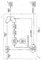
- FIG. 1 illustrates a present A/V system 10 having a VCR 12 and a display device 14 (e.g., television) that employs such a control methodology.
- Menus associated with controlling VCR 12 are generated by the VCR 12 and are provided to the display device 14 via the NTSC output of the VCR 12 as a composite video.
- DTV digital TV
- U.S. Pat. No. 5,608,730 discloses a bi-directional communication system, wherein a transmitting device can lock and unlock a receiving device. Audio/video data is transmitted on separate dedicated lines, which are not part of the D2B bus, for example, L1, L2, or L3, between devices. Control data for controlling the receiving device or data indicative of the status of the device is transmitted, preferably in conformance with D2B, via a separate bi-directional bus. A display device may display messages based on this data. A means to "lock" the receiving device is provided if the amount of data to be transmitted is greater than 16 bytes.
- U.S. Pat. Nos. 5,617,330 discloses an architecture that utilizes the D2B bus.
- the D2B bus is a control bus that is not designed to pass audio/video content.
- audio/video content would be transferred using typical analog connections that are not part of the D2B bus.
- this patent teaches a local communication system, wherein messages from more than one device may be simultaneously displayed. The audio and video signals are passed between the devices via a separate and unique path (see col. 2, lines 39-45).
- U.S. Pat. No. 5,499,018 also discloses an architecture that utilizes the D2B bus.
- this patent teaches a local communication system, wherein compound messages indicating the status of the system are compiled from more than one device using audio/video controller ("AVC") sub-devices to interrogate the device. That is, the AVC of each device is connected via a D2B bus and provides control and systematic interrogation of all the sub-devices within each device. Audio/video signals are passed between the devices via separate and unique paths, for example, A, F and L (see col. 2, lines 39-45).
- AVC audio/video controller
- U.S. Pat. No. 5,617,571 teaches a solution for turning off the power of an individual audio/video unit that is interconnected via a D2B bus. As noted above, in such an arrangement, the audio/video signals and control signals are passed between devices via separate buses (see Fig. 1).
- This patent application defines a minimal level of interoperability for exchanging audio/video (A/V) content and associated control between common consumer electronic (CE) devices.
- An interface based on the IEEE 1394 serial bus for the physical and link layers makes use of a control language such as CAL or AV/C for managing OSDs and connectivity issues.
- CAL or AV/C control language
- a video source is chosen on the display device and the user then interacts directly with the device to be controlled (i.e., peripheral device (e.g., VCR)) using the remote control.
- peripheral device e.g., VCR
- the invention defines transferring On Screen Displays (OSDs) (e.g., menus) from a peripheral device (such as a digital VCR or DVHS) to a controlling device (such as a digital television or DTV) using one of several formats such as (1) sending one frame of video either over the asynchronous using a push method or pull method triggered by a message from the peripheral device to the DTV or over an isochronous channel; (2) transfer a run-length-encoded version of the OSD; (3) transfer the actual information in an OSD bitmap format; ( 4) MPEG-I frame stills transported over the Isochronous link.
- OSDs On Screen Displays
- peripheral device would not use MPEG-I frames for menus since it is difficult to represent text using this method and it is expensive to encode pictures in real time.
- peripheral devices that want to supply an MPEG picture as a background for the menu would be able to do it.
- the Push method involves writing the menu of the peripheral device (i.e., the device to be controlled) directly into a bit buffer of the DTV which is available via the IEEE 1394 serial bus.
- the peripheral device can update the sections of the display that have changed, and let the DTV know when it is finished so that it can dump the updated menu in the Video RAM for display.
- a PULL method may be employed.
- OSD Management Messages and connection management messages will be defined as general structures that can be carried via AV/C or CAL. It should be noted however that these messages will be able to easily be carried by other means.
- a focus of the present invention is to enable the capability of carrying A/V information over a digital link and providing a means for an A/V device to display its menu or Graphical User Interface (GUI). Further, the present invention relies on a user-machine control paradigm as opposed to the machine-machine paradigm which has previously been commonly discussed with respect to IEEE 1394 and CEBus control.
- the present invention supports using IEC61883 for carrying A/V data across the isochronous channels and 61883 FCP may be used to encapsulate the CAL or AV/C command directly over IEEE 1394 serial bus and therefore allows for coexistence with other control languages.
- Many of the devices will use a registry table that is built during a discovery process which looks at information stored in each instrument's Self Describing Device Table (SDDT).
- SDDT may contain such information as a unique ID, node address; etc.
- the registry tables would be used by the DTV to build a menu to allow the user to set up connections between components (similar to the user selecting the composite input. for the source of their TV today).
- peripheral device displays its menu or GUI on the DTV and accepts commands directly. For example, little of a control language is required to be defined for basic interoperability and device models are not needed. Further, since inputs go directly to the peripheral device and the. OSD is defined as a form of basic video, the control is totally independent of the type of device being controlled thereby assuring long term interoperability.
- a control language is required to manage the network, OSD, and for optionally transporting universal commands across the bus.
- AV/C, CAL or any equivalent control language may be successfully employed in connection with practicing this invention.
- IEEE 1394 serial bus has been suggested for many applications within a Home Network environment. It is being discussed within Video Electronics Standards Association (VESA) for use as a "whole home network.” It is being built into the next generation PCs and will be used for many local peripherals including disc drives. It is also clear that this will be an important interface for digital A/V consumer electronic devices such as digital televisions and VCRs. Within the entertainment cluster composed of consumer electronic audio/video devices, there are many different levels of interface support at the application level.
- VESA Video Electronics Standards Association
- IEEE-1394 is a high speed, low cost digital serial bus 16 developed for use as a peripheral or back-plane bus. Some of the highlights of the bus include: Dynamic node address assignments, Data rates of 100, 200, and 400 Mbits/sec, Asynchronous and isochronous modes, fair bus arbitration, and consistency with ISO/IEC 13213.
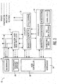
- Figure 3 illustrates the serial bus protocol for the IEEE 1394 serial bus as a set of three stacked layers.
- the physical layer 18 has physical signaling circuits and logic that are responsible for power-up initialization, arbitration, bus-reset sensing, and data signaling. Two shielded low-voltage differential signal pairs, plus a power pair are defined for the IEEE-1394 cable. Signaling is done by using Data-Strobe bit-level encoding which doubles jitter tolerance.
- Data is formatted into packets in the link layer 20.
- Two classes of data communication between devices are supported: asynchronous and isochronous.
- Asynchronous communication can be characterized as "allows acknowledgment,” while isochronous communication can be characterized as “always on time.”
- the asynchronous service will be used primarily for control and status messages while isochronous communication will be used for data streams such as MPEG video.
- the timely nature of isochronous communication is achieved by providing a cycle every 125 ⁇ sec. Isochronous cycles take priority over asynchronous communication.
- Asynchronous transfer can take place any time the bus is free. A minimum of 25 ⁇ sec out of every 125 ⁇ sec cycle is reserved for asynchronous data transfer.
- Isochronous transfer provides a real-time data transfer mechanism. An ongoing isochronous communication between one or more devices is referred to as a channel. The channel has to be established first, then the requesting device is guaranteed to have the requested amount of bus time every cycle.
- the transaction layer 22 defines a complete request-reply protocol to perform bus transactions. Although transaction layer 22 does not add any services for isochronous data transfer, it does provide a path for management of the resources needed for isochronous services. This is done through reads and writes to the control status register (CSR). Transaction layer 22 also defines a retry mechanism to handle situations where resources are busy and unable to respond. Asynchronous data is transferred between IEEE-1394 nodes utilizing one of three transactions; "read-data" for retrieving data from a different node, "write-data” for transferring data to a different node and “lock-data” for transferring data to a different node for processing and then the data is returned back to the original node.
- CSR control status register
- Serial bus management 24 describes the protocols, services, and operating procedures whereby one node is selected and may then exercise management level control over the operation of the remaining nodes on the bus.
- the bus manager 28 provides a number of services including; maintenance of the speed and topological map, and bus optimization.
- the isochronous resource manager provides facilities for allocation of isochronous bandwidth, allocation of channel numbers, and the selection of the cycle master.
- node controller 30 implements the CSRs required by all serial bus nodes and communicates with the physical 18, link 20, and transaction 22 layers and any application present in the device.
- Node controller 30 component as well as CSR and configuration ROM facilities are used to configure and manage the activities at an individual node.
- IRM Isochronous Resource Manager
- BM Bus Manager
- the IRM 26 provides the resources necessary for the serial bus to cooperatively allocate and de-allocate the isochronous resources, (channels and bandwidth), required for orderly isochronous operations.
- the IRM 26 provides a common location for the other nodes to check on availability of channels and bandwidth, and to register their new allocations.
- the IRM 26, whose location is known immediately upon completion of the self identify process, also provides a common location where serial bus nodes may determine the identity of the BM 28, if one is present.
- the BM 28, if present, provides management services to other nodes on the serial bus. These include activation of a cycle master, performance optimization, power management, speed management and topology management.
- FCP Functional Control Protocol
- IEEE-1394 asynchronous write packet for sending commands and responses.
- the IEEE-1394 asynchronous packet structure with FCP imbedded in the data field shown below.
- the Command/Transaction SET specifies the command set (e.g. AV/C, CAL).
- FCP frames are classified as command frames, and response frames.
- the command frame is written into a command register on a peripheral device and the response frame is written into a response register on a controller.
- the standard specifies two addresses for the command and the response.
- the structure of the isochronous packet in IEC-61883 is shown below.
- the packet header is composed of two quadlets of an IEEE-1394 isochronous packet. (A quadlet is defined as four 8-bit bytes.)
- the Common Isochronous Packet (CIP) header is placed at the beginning of the data field of an IEEE-1394 isochronous packet, immediately followed by the real time data.
- Data length is the data field length in bytes
- Tag indicates whether CIP exist (01) or not (00)
- Channel specifies the isochronous channel number
- Tcode 1010
- Sy is an application specific control field.
- SID is Source node_ID
- DBS is data block size in quadlets
- Fraction Number (FN) allow you to divide source packets for bus time utilization
- Quadlet Padding Count (QPC) indicates number of quadlets count
- SPH Source Packet Header
- rsv indicates reserved for future
- DBC Data Block Counter
- FMT indicates the format ID such as MPEG2, DVCR
- FDF Format Dependent field
- Plugs and plug control registers are special purpose CSR registers.
- CMP Connection Management. Procedures
- Isochronous data flows from one transmitting device to zero or more receiving devices by sending the data on one isochronous channel on the IEEE-1394 bus.
- Each isochronous data flow is transmitted to an isochronous channel through one output plug on the transmitting device and is received from the isochronous channel through one input plug on each of the receiving devices.
- oPCR output Plug Control Register
- oMPR output Master Plug Register
- oPCR output plug control register
- oMPR output master plug register
- iPCR input plug control register
- iMPR input master plug register
- the major steps involved in establishing a connection are allocation of IEEE 1394 resources (e.g. bandwidth) and setting channel, data-rate, overhead-ID and connection counter in oPCR and iPCR.
- IEEE 1394 resources e.g. bandwidth
- An isochronous data flow can be controlled by any device connected to the IEEE 1394 serial bus by modifying the corresponding plug control registers.
- Plug control registers can be modified by asynchronous transactions on IEEE 1394 serial bus, the preferred method of connection management is through the use of AV/C. It is fully within the scope of this invention that CAL may be utilized for connection management.
- CAL and AV/C are control languages that distinguish between logical and physical entities.
- a television i.e., a physical entity
- functional components i.e., logical entities
- Such control languages provide two main functions: Resource allocation and Control.
- Resource allocation is concerned with requesting, using and releasing Generic Network resources.
- Messages and control are transported by the FCP as defined in IEC-61883 and discussed above.
- CAL has adopted an object base methodology for its command syntax.
- An object contains and has sole access to.a set number of internal values known as instance variables (IV).
- Each object keeps an internal list of methods.
- a method is an action that an object takes as a result of receiving a message.
- a message consists of a method identifier followed by zero or more parameters.
- an object receives a method, it looks through its list of methods for one which matches the method identified in the message. If found, the method will be executed. The parameters supplied with the message determine the exact execution of the method.
- control languages is based on the assumption that all consumer electronic products have a hierarchical structure of common parts or functions. For example, CAL treats each product as a collection of one or more of these common parts called Contexts. These contexts are designed to allow access to product functionality in a uniform way.
- the context data structure is a software model defined in each device that models the operation of all device functions.
- a context consists of one or more objects grouped together to form a specific functional sub-unit of a device. Like an object, context is a model of a functional sub-unit. Devices are defined by one or more contexts. CAL has defined a large set of contexts to model various types of consumer electronic devices. Each context, regardless of what product it is in, operates the same way.
- Objects are defined by a set of IVs, for example the IVs for a binary switch object contain required and optional IVs.
- Required IVs include a variable (current_position) that indicates whether the switch is on or off and the default position (default_position) of the switch.
- Optional IVs include function_of_positions; reporting_conditions; dest_address; previous_value and report_header.
- IVs are just like variables in any software program and are supported in CAL as Boolean, Numeric, Character, and Data (array).
- the IVs in an object can be categorized into three general groups: support IVs, reporting IVs, and active IVs.
- the support IVs are usually read only variables that define the installation use of the object and operation of the active IVs.
- Active IVs of an object are the variables that are primarily set or read to operate the object.
- controller e.g., digital television
- target or peripheral device e.g., digital VCR
- A/V analog audio/video
- OSD on-screen display
- the present application defines a base level of interoperability between devices from different manufacturers at a minimal cost.
- the users have the capability to interact with the A/V devices interconnected via an IEEE 1394 serial bus in a manner to which they are accustomed (i.e. use of an RC unit possibly in connection with an OSD).
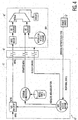
- Figure 4 defines such a system 10" for providing interoperability between digital A/V devices interconnected via an IEEE 1394 serial bus.
- interoperability is achieved by transferring the menu or GUI information directly from the peripheral device 12" (e.g., DVCR) to controlling device 14" (e.g., DTV) utilizing one of the below-defined methodologies.
- the menu is not transferred as a composite video stream which would require first passing the menu information through a MPEG encoder contained in the peripheral device.
- the menu is transferred via serial bus 16" to DTV 14" where the menu information is overlayed in DTV 14" with the decoded MPEG stream prior to being displayed.
- a "Pull" method to transfer the OSD information from the peripheral device or DVCR 12"to the display capable controlling device or DTV 14" may be used.
- the bulk of the OSD data is transferred from the peripheral device to a display device by asynchronous read requests issued by the display device. That is, the display device reads the OSD information from the memory of the peripheral device by making use of at least one block read transaction of IEEE 1394.
- the display device is informed of the location and size of the OSD data via a "trigger" command which is sent from the peripheral device to the display device when the peripheral device is ready to begin transferring data.
- the display device Since the OSD information on the peripheral device is updated in response to user entered data (such as from a remote controller 13), the display device is alerted of the availability of newly updated data. This can be achieved by sending a short message (i.e., "trigger") to the OSD object of the controlling device. It should be noted that such a message needs to inform the display device of the starting location as well as length of the OSD data to be read. The length is necessary since the application in the controlling device is going to make use of asynchronous read transactions of IEEE 1394.
- the controller may initiate multiple block read transactions until all the OSD information has been read.
- a field indicating the type of OSD data is useful. This is especially useful since in this case the same mechanism can also be used to trigger the OSD mechanism of a display device to display such things as error, warning and/or status messages.
- the differentiation of the type of OSD data is helpful for the display device and/or user to decide whether it really wants it to be displayed (for example a user watching a movie may want to ignore things such as status messages).
- the peripheral devices may indicate to the controller (i.e., display device) that it has OSD data ready to be transferred.
- An OSD Trigger message containing the starting offset address, length of the OSD data and the OSD_type information is sent to the controller. The format of one such a message is defined below. This information will be used to determine the number of read requests it need to generate.
- the display device would pull the menu by reading it from the peripheral devisee's bus mapped memory space. This message could be encapsulated in CAL or AV/C.
- OSD_data_type 8 bit field indicating the type of OSD data presented.
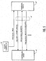
- a typical ordered flow may include the following messages, as illustrated in Figure 5.
- the peripheral device e.g:, digital VCR 12
- the peripheral device provides a message to the controller (e.g., digital television 14") which includes the starting location and the length of the OSD information corresponding to the appropriate menu.
- the controller sends a message to the peripheral device indicating a block read request.
- the peripheral device responds with a block read response and OSD data. This is repeated until the entire menu is transferred to the controller.
- An asynchronous push method which primarily uses IEEE 1394 asynchronous write transactions initiated by the peripheral device may be used to write the OSD data onto the controller.
- This approach allows a peripheral device to write its menu contents into a controller device. Since it is expected that the menus will be larger than the MTU (Maximum Transfer Unit) of the bus, a fragmentation header can be added.
- the menu transport layer should add this header. On the receiving side, this layer reassembles the menu and passes it to higher layers.
- a possible fragmentation header is defined below.
- the fragmentation header is one quadlet and contains a sequence number and the source of the fragment. Fragment sequence no (2) bytes Fragment source (node_id) (2) bytes
- An isochronous transport method provides for broadcasting the OSD data over one of the Isochronous channels provided by IEEE 1394. Bandwidth would need to be reserved and held as long as the peripheral is being controlled using the OSD. It would also be possible that there would not be enough bandwidth left for the reservation of the channel. This could create a situation where the user is not able to get the feedback they require.
- An Asynchronous Stream method would be similar to the Isochronous Stream method except that it would use an Asynchronous Stream to carry the OSD information.
- An Asynchronous Stream is essentially the same as an Isochronous Stream except that there is no bandwidth reservation and the stream is sent in the Asynchronous portion of the bus cycle.
- a peripheral device During operation through a direct link, a peripheral device simply receives inputs from its RC unit or front panel and carries out corresponding actions. However, there is a slight complication when, as a result of these actions, an OSD is supposed to be generated on a display device. Since in this case, the actions of the peripheral device were initiated through its own direct link, the peripheral device has no knowledge as to which node on the network to display its OSD. (The peripheral device constructs the OSD data (i.e., OSD blocks defined by a header) and stores it in its memory area.) Therefore a device which detects initiation of control through its direct link, can send OSD_info messages to each OSD capable device (i.e., devices which have implemented the OSD object).
- OSD data i.e., OSD blocks defined by a header
- the OSD_info message includes a field for OSD_data_type to indicate whether the OSD data presented to the display device is a warning message, error message, normal OSD data etc.
- OSD data can also be in a descriptive form such as HTML.
- HTML would be used only for describing how the OSD would look. HTML would not be used for control as it is for the Internet.
- the OSD module in the Display Device requests memory accesses starting at the memory location in the trigger message.
- the OSD Module reads the OSD Block 1.
- the data is received using IEEE 1394 read commands and transferred to the display memory area in the display device. This data is then stored in the Display device's internal memory in the format required by the Display device's OSD controller.
- the discovery process allows the controlling device to discover other devices in the network. This process is activated by a bus reset and serves to search and discover existing devices on the network.
- a bus reset may be caused by connecting/disconnecting a device, software initiated reset etc.
- This software module relies on some information stored on each device configuration ROM. This information is referred to as Self Description Device (SDD) and contains information such as Model #, Location of menu, URL, EUI Vendor ID etc.
- SDD Self Description Device
- the SDDT of a Display/Controller contains a pointer to an information block which contains information about the display capabilities of the device.
- the information block may include; type of display ( interlaced or progressive ), maximum bytes per line, true color capability, resolution modes supported ( full, 1 / 2, 1 / 3 ), maximum bits/pixel supported for palette mode ( 2, 4, 8 ), etc.
- Other methods of discovery can also be used to obtain this information, such as the Home Plug and Play as defined for CAL or the subunit descriptors defined for AV/C.
- the discovery manager reads the SDD information located in the ROM of each connected device. This information will be built into a registry table.
- Each device on the IEEE 1394 serial bus will have a registry table which will be used to keep track of other devices on the bus and their capabilities. For all devices on the bus, this device registry (registry table) will be constantly updated in the discovery process on bus resets.
- the Registry provides services to the application for mapping volatile characteristics like IEEE 1394 node_ID, IP address etc. to a non-volatile identification scheme used by the application.
- the application uses the non-volatile 64-bit EUI (Extended Unique Identifier) for identifying any node on IEEE 1394 serial bus.
- the services of Registry are used to map this 64-bit EUI to volatile IEEE 1394 node_ID or IP.
- the “Registry” module is a system service module.
- the “Registry” system module allows the communication between the nodes within the home network by abstracting their location inside the home network.
- the registry table is maintained by the Registry manager within each device and contains the information for each node to provide the service previously specified. This registry table is constantly updated by the Discovery manager on bus resets.
- Each row of the Registry Table can be as follows: 64-bit EUI 1394 node_ID IP address Manufac/ Model# Device Type
- the application can use the registry to determine the IEEE 1394 . address for any node on the home network based on the 64-bit EUI of that node.
- the registry will be built during the discovery process after a bus reset. Correlation to a stable identifier such as the EUI is important since node addresses can change during a bus reset.
Applications Claiming Priority (7)
| Application Number | Priority Date | Filing Date | Title |
|---|---|---|---|
| US71341 | 1979-05-02 | ||
| US5950797P | 1997-09-18 | 1997-09-18 | |
| US59507 | 1997-09-18 | ||
| US6678297P | 1997-11-25 | 1997-11-25 | |
| US66782 | 1997-11-25 | ||
| US7134198P | 1998-01-14 | 1998-01-14 | |
| PCT/US1998/019483 WO1999014945A1 (en) | 1997-09-18 | 1998-09-18 | Peripheral electronic device and system for controlling this device via a digital bus |
Publications (2)
| Publication Number | Publication Date |
|---|---|
| EP1016270A1 EP1016270A1 (en) | 2000-07-05 |
| EP1016270B1 true EP1016270B1 (en) | 2004-02-04 |
Family
ID=27369662
Family Applications (2)
| Application Number | Title | Priority Date | Filing Date |
|---|---|---|---|
| EP98946107A Expired - Lifetime EP1016270B1 (en) | 1997-09-18 | 1998-09-18 | Peripheral electronic device and system for controlling this device via a digital bus |
| EP98946123A Expired - Lifetime EP1016271B1 (en) | 1997-09-18 | 1998-09-18 | Digital television apparatus for controlling a peripheral device via a digital bus |
Family Applications After (1)
| Application Number | Title | Priority Date | Filing Date |
|---|---|---|---|
| EP98946123A Expired - Lifetime EP1016271B1 (en) | 1997-09-18 | 1998-09-18 | Digital television apparatus for controlling a peripheral device via a digital bus |
Country Status (8)
| Country | Link |
|---|---|
| US (1) | US6665020B1 (ja) |
| EP (2) | EP1016270B1 (ja) |
| JP (3) | JP4611516B2 (ja) |
| KR (2) | KR100560549B1 (ja) |
| CN (2) | CN1181677C (ja) |
| AU (2) | AU9319298A (ja) |
| DE (3) | DE69821503T2 (ja) |
| WO (2) | WO1999014945A1 (ja) |
Families Citing this family (82)
| Publication number | Priority date | Publication date | Assignee | Title |
|---|---|---|---|---|
| US7068920B1 (en) * | 1998-02-04 | 2006-06-27 | Thomson Licensing | Digital baseband interface for a DVD player |
| DE69941354D1 (de) * | 1998-02-04 | 2009-10-15 | Thomson Consumer Electronics | Digitale basisbandschnittstelle für ein dvd wiedergabegerät |
| CN1867068A (zh) | 1998-07-14 | 2006-11-22 | 联合视频制品公司 | 交互式电视节目导视系统及其方法 |
| JP2000156031A (ja) * | 1998-11-17 | 2000-06-06 | Sony Corp | 情報処理システム、情報処理装置、及び情報処理方法 |
| US6859799B1 (en) | 1998-11-30 | 2005-02-22 | Gemstar Development Corporation | Search engine for video and graphics |
| JP2001028763A (ja) * | 1999-04-29 | 2001-01-30 | Mitsubishi Electric Inf Technol Center America Inc | コントローラからビデオ表示ユニットに画像データを転送する方法、ビデオ表示ユニットアダプタ、ビデオ表示システム、並びにテレビ表示画面上への提示のために画像データをダブルバッファリングする方法 |
| US6775244B1 (en) | 1999-06-21 | 2004-08-10 | Intel Corporation | Gathering of device discovery information |
| US7032024B1 (en) * | 1999-07-29 | 2006-04-18 | Samsung Electronics Co., Ltd. | Connection management method for devices connected digital interface and command structure therefor |
| US7068674B1 (en) | 1999-08-23 | 2006-06-27 | Lg Electronics Inc. | Method of controlling connection between nodes in digital interface |
| JP2001086144A (ja) * | 1999-09-16 | 2001-03-30 | Sony Corp | ユニット接続設定方法およびユニット接続設定装置 |
| JP2001119767A (ja) | 1999-10-19 | 2001-04-27 | Sony Corp | 情報処理装置および方法、情報処理システム並びに記録媒体 |
| US6937599B1 (en) * | 1999-10-21 | 2005-08-30 | Matsushita Electric Industrial Co., Ltd. | Data source, data conversion device, inverse data conversion device, auxiliary data file generation device, reception method, medium and information aggregate |
| JP2001136185A (ja) * | 1999-11-09 | 2001-05-18 | Sony Corp | 伝送方法、伝送システム及び伝送制御装置 |
| DE19956815B4 (de) * | 1999-11-25 | 2006-06-14 | Benq Corp., Kweishan | Monitor in Verbindung mit einer Zeigevorrichtung zum Einstellen von Bildern auf einem Schirm |
| KR100383843B1 (ko) * | 1999-12-27 | 2003-05-14 | 엘지전자 주식회사 | 외부 연결기기에 대한 영상기기의 메뉴 원격제어방법 |
| KR100359842B1 (ko) * | 2000-03-08 | 2002-11-07 | 엘지전자 주식회사 | 오디오 메뉴 표시 방법 |
| KR20010097454A (ko) * | 2000-04-24 | 2001-11-08 | 윤종용 | 온 스크린 디스플레이 오브젝트 표시방법 및 표시장치 |
| JP2001325206A (ja) * | 2000-05-12 | 2001-11-22 | Canon Inc | 表示装置、表示システム及びコンピュータ読み取り可能な記憶媒体 |
| KR100694043B1 (ko) * | 2000-05-18 | 2007-03-12 | 삼성전자주식회사 | Av 시스템 및 그 기능 확장 모듈 |
| US7103906B1 (en) | 2000-09-29 | 2006-09-05 | International Business Machines Corporation | User controlled multi-device media-on-demand system |
| DE60135567D1 (de) | 2000-10-11 | 2008-10-09 | United Video Properties Inc | Systeme und verfahren zur bereitstellung von datenspeichern in servern in einem medien-auf-anfrage liefersystem |
| US6826699B1 (en) * | 2000-10-19 | 2004-11-30 | Sony Corporation | Method and apparatus for performing authentication and key exchange protocols with multiple sink devices |
| US7859601B2 (en) * | 2001-04-12 | 2010-12-28 | Sony Corporation | Signal processing device, housing rack, and connector |
| JP4104300B2 (ja) * | 2001-06-25 | 2008-06-18 | 三洋電機株式会社 | 複数機器制御システム |
| US7574723B2 (en) * | 2001-07-19 | 2009-08-11 | Macrovision Corporation | Home media network |
| US7292775B1 (en) | 2001-09-20 | 2007-11-06 | Keen Personal Media, Inc. | Communicating program identifiers from a digital video recorder (DVR) to a set top box (STB) independent of when the STB demodulates the associated program data |
| US7325244B2 (en) * | 2001-09-20 | 2008-01-29 | Keen Personal Media, Inc. | Displaying a program guide responsive to electronic program guide data and program recording indicators |
| US8931010B2 (en) | 2002-11-04 | 2015-01-06 | Rovi Solutions Corporation | Methods and apparatus for client aggregation of media in a networked media system |
| US8028093B2 (en) | 2002-12-11 | 2011-09-27 | Broadcom Corporation | Media processing system supporting adaptive digital media parameters based on end-user viewing capabilities |
| US7475243B2 (en) * | 2002-12-11 | 2009-01-06 | Broadcom Corporation | Preventing a non-head end based service provider from sending media to a media processing system |
| US9357256B2 (en) * | 2002-12-11 | 2016-05-31 | Broadcom Corporation | Third party media channel access in a media exchange network |
| US8495180B2 (en) * | 2002-12-11 | 2013-07-23 | Broadcom Corporation | Server architecture supporting a personal media exchange network |
| US7584359B2 (en) | 2002-12-11 | 2009-09-01 | Broadcom Corporation | Secure media peripheral association in a media exchange network |
| US7450501B2 (en) | 2002-12-11 | 2008-11-11 | Broadcom Corporation | Media processing system based on satellite set top box platform with telephony downstream and upstream data paths |
| US7493646B2 (en) | 2003-01-30 | 2009-02-17 | United Video Properties, Inc. | Interactive television systems with digital video recording and adjustable reminders |
| US7129855B2 (en) * | 2003-09-26 | 2006-10-31 | Openpeak Inc. | Device control system, method, and apparatus |
| US7213228B2 (en) | 2003-03-17 | 2007-05-01 | Macrovision Corporation | Methods and apparatus for implementing a remote application over a network |
| JP4623599B2 (ja) * | 2003-05-05 | 2011-02-02 | トムソン ライセンシング | 自動再生/自動一時停止機能を使用して外部デバイスを制御するための方法および装置 |
| WO2005004404A1 (en) * | 2003-07-03 | 2005-01-13 | Thomson Licensing | Method for controlling a network station in a network of a first type from a network station in a network of a second type, and connection unit for the connection of the networks of the first and second types |
| CN100423576C (zh) * | 2003-07-22 | 2008-10-01 | 威鲸资讯有限公司 | 一种可共用影音输出装置的系统 |
| US7579961B2 (en) * | 2003-09-26 | 2009-08-25 | Openpeak Inc. | Device control system, method, and apparatus |
| CN100536540C (zh) * | 2003-11-10 | 2009-09-02 | 汤姆森许可贸易公司 | 用于提供与网络中的设备相关联的内容信息的动态显示的方法和设备 |
| US7171506B2 (en) * | 2003-11-17 | 2007-01-30 | Sony Corporation | Plural interfaces in home network with first component having a first host bus width and second component having second bus width |
| CN100375512C (zh) * | 2004-02-27 | 2008-03-12 | 联想(北京)有限公司 | 一种音视频播放方法 |
| US8302134B2 (en) * | 2004-03-26 | 2012-10-30 | Sony Corporation | Systems and methods for television antenna operation |
| US8543723B2 (en) * | 2004-07-27 | 2013-09-24 | Sony Corporation | Home network system with transmission error recovery |
| KR100574463B1 (ko) * | 2004-08-05 | 2006-04-27 | 삼성전자주식회사 | Ieee 1394가 채용된 호스트장치 및 그의 제어방법 |
| US8086575B2 (en) | 2004-09-23 | 2011-12-27 | Rovi Solutions Corporation | Methods and apparatus for integrating disparate media formats in a networked media system |
| US20060098939A1 (en) * | 2004-11-09 | 2006-05-11 | Samsung Electronics Co., Ltd. | Combination system capable of controlling each device through a single OSD menu and method thereof |
| TWI248762B (en) * | 2004-11-10 | 2006-02-01 | Realtek Semiconductor Corp | Video processing device and method thereof |
| US7768388B2 (en) | 2005-01-05 | 2010-08-03 | Rovi Solutions Corporation | Methods and apparatus for providing notifications in a media system |
| KR100747853B1 (ko) * | 2005-07-01 | 2007-08-08 | 엘지전자 주식회사 | 영상표시기기의 언어설정 장치 및 방법 |
| US9467322B2 (en) | 2005-12-27 | 2016-10-11 | Rovi Solutions Corporation | Methods and apparatus for integrating media across a wide area network |
| US9681105B2 (en) | 2005-12-29 | 2017-06-13 | Rovi Guides, Inc. | Interactive media guidance system having multiple devices |
| US7929551B2 (en) | 2006-06-01 | 2011-04-19 | Rovi Solutions Corporation | Methods and apparatus for transferring media across a network using a network interface device |
| US9319741B2 (en) | 2006-09-07 | 2016-04-19 | Rateze Remote Mgmt Llc | Finding devices in an entertainment system |
| US8607281B2 (en) | 2006-09-07 | 2013-12-10 | Porto Vinci Ltd. Limited Liability Company | Control of data presentation in multiple zones using a wireless home entertainment hub |
| US8966545B2 (en) * | 2006-09-07 | 2015-02-24 | Porto Vinci Ltd. Limited Liability Company | Connecting a legacy device into a home entertainment system using a wireless home entertainment hub |
| US9233301B2 (en) * | 2006-09-07 | 2016-01-12 | Rateze Remote Mgmt Llc | Control of data presentation from multiple sources using a wireless home entertainment hub |
| US20080061578A1 (en) * | 2006-09-07 | 2008-03-13 | Technology, Patents & Licensing, Inc. | Data presentation in multiple zones using a wireless home entertainment hub |
| US8935733B2 (en) * | 2006-09-07 | 2015-01-13 | Porto Vinci Ltd. Limited Liability Company | Data presentation using a wireless home entertainment hub |
| US8005236B2 (en) | 2006-09-07 | 2011-08-23 | Porto Vinci Ltd. Limited Liability Company | Control of data presentation using a wireless home entertainment hub |
| US9386269B2 (en) * | 2006-09-07 | 2016-07-05 | Rateze Remote Mgmt Llc | Presentation of data on multiple display devices using a wireless hub |
| JP4957142B2 (ja) * | 2006-09-21 | 2012-06-20 | ソニー株式会社 | 再生装置、再生方法および再生プログラム |
| KR101320850B1 (ko) * | 2006-12-21 | 2013-10-21 | 삼성전자주식회사 | 제어소유권을 등록하여 외부기기를 제어하는 영상디스플레이 장치 및 그 제어방법 |
| US20090019492A1 (en) | 2007-07-11 | 2009-01-15 | United Video Properties, Inc. | Systems and methods for mirroring and transcoding media content |
| US20090182904A1 (en) * | 2008-01-10 | 2009-07-16 | Sony Corporation | System and Method for Providing Peripheral Device Functionality |
| US20110182278A1 (en) * | 2008-10-03 | 2011-07-28 | Leonard Tsai | Eui based remote database for dynamic device control |
| US10063934B2 (en) | 2008-11-25 | 2018-08-28 | Rovi Technologies Corporation | Reducing unicast session duration with restart TV |
| US20100245667A1 (en) * | 2009-03-24 | 2010-09-30 | Sony Corporation | Non-standalone tv pc |
| US9014546B2 (en) | 2009-09-23 | 2015-04-21 | Rovi Guides, Inc. | Systems and methods for automatically detecting users within detection regions of media devices |
| CN101854502B (zh) * | 2010-04-02 | 2013-04-17 | 深圳创维-Rgb电子有限公司 | 一种电视中的语言处理方法和系统 |
| CN102347928B (zh) * | 2010-07-29 | 2014-01-15 | 鸿富锦精密工业(深圳)有限公司 | 数字媒体设备及利用其实现关机设备内容共享的方法 |
| US9854318B2 (en) | 2011-06-06 | 2017-12-26 | Rovi Guides, Inc. | Systems and methods for sharing interactive media guidance information |
| US11295603B2 (en) * | 2011-10-28 | 2022-04-05 | Universal Electronics Inc. | System and method for optimized appliance control |
| US8805418B2 (en) | 2011-12-23 | 2014-08-12 | United Video Properties, Inc. | Methods and systems for performing actions based on location-based rules |
| KR101889927B1 (ko) * | 2012-05-22 | 2018-08-21 | 삼성전자주식회사 | 전자 장치, 전자 장치 및 중계 장치를 포함하는 시스템 및 그 제어 방법 |
| US9674563B2 (en) | 2013-11-04 | 2017-06-06 | Rovi Guides, Inc. | Systems and methods for recommending content |
| US9934180B2 (en) * | 2014-03-26 | 2018-04-03 | Pqj Corp | System and method for communicating with and for controlling of programmable apparatuses |
| CN104648879B (zh) * | 2015-01-23 | 2018-06-08 | 徐州德坤电气科技有限公司 | 一种基于数字总线的智能物流托载运输单元 |
| CN105472454A (zh) * | 2015-12-29 | 2016-04-06 | 惠州市伟乐科技股份有限公司 | 一种用于解码器的信号格式自动检测方法 |
| US9854654B2 (en) | 2016-02-03 | 2017-12-26 | Pqj Corp | System and method of control of a programmable lighting fixture with embedded memory |
Family Cites Families (40)
| Publication number | Priority date | Publication date | Assignee | Title |
|---|---|---|---|---|
| JPH0710117B2 (ja) * | 1989-12-20 | 1995-02-01 | 松下電器産業株式会社 | リモートコントロール方法 |
| GB9106113D0 (en) * | 1991-03-22 | 1991-05-08 | D2B Systems Co Ltd | Local communication bus system and apparatus for use in such a system |
| EP0510739B1 (en) * | 1991-03-22 | 1999-02-10 | D2B Systems Co. Ltd. | Local communication bus system and apparatuses for use in such a system |
| JPH0581736A (ja) * | 1991-08-02 | 1993-04-02 | Sony Corp | データ処理装置 |
| JPH0622108U (ja) * | 1992-08-28 | 1994-03-22 | 株式会社東海理化電機製作所 | 車両用負荷の遠隔制御用受信装置 |
| JP3272046B2 (ja) * | 1992-09-22 | 2002-04-08 | 三洋電機株式会社 | リモコン送信器、及び該リモコン送信器によって操作制御される操作対象機器、並びにそれらを用いたリモコンシステム |
| JP3158364B2 (ja) * | 1992-10-13 | 2001-04-23 | ソニー株式会社 | 電子機器 |
| JP3611588B2 (ja) * | 1992-12-21 | 2005-01-19 | ソニー株式会社 | 送信方法、受信方法、通信方法及び双方向バスシステム |
| JPH06245265A (ja) * | 1993-01-12 | 1994-09-02 | Sony Corp | Avシステムのシステムフィーチャー起動方法及び管理方法 |
| US5488357A (en) * | 1993-01-06 | 1996-01-30 | Sony Corporation | Remote controlling method and system feature starting method and controlling method for audio/visual system |
| JP3199084B2 (ja) * | 1993-01-06 | 2001-08-13 | ソニー株式会社 | Avシステムのリモートコントロール方法 |
| JPH0744474A (ja) * | 1993-07-30 | 1995-02-14 | Canon Inc | システム制御方式及び装置 |
| JPH0744477A (ja) * | 1993-07-30 | 1995-02-14 | Canon Inc | マルチメディア機器の制御システム |
| JPH0779411A (ja) * | 1993-09-06 | 1995-03-20 | Sony Corp | 画像信号再生方法および画像信号再生装置、ならびに 画像信号記録媒体 |
| GB9325299D0 (en) * | 1993-12-10 | 1994-02-16 | D2B Systems Co Ltd | Local communication system and station for use in as system |
| US5682599A (en) * | 1993-12-24 | 1997-10-28 | Sony Corporation | Two-way broadcasting and receiving system with time limit and/or limit data |
| US5635979A (en) * | 1994-05-27 | 1997-06-03 | Bell Atlantic | Dynamically programmable digital entertainment terminal using downloaded software to control broadband data operations |
| JP3201140B2 (ja) * | 1994-05-31 | 2001-08-20 | ソニー株式会社 | 電子機器装置 |
| JP3291926B2 (ja) * | 1994-07-07 | 2002-06-17 | ソニー株式会社 | 電子機器制御方式 |
| JPH0879847A (ja) * | 1994-09-05 | 1996-03-22 | Hitachi Ltd | 情報システム及び該システムを構成するav機器及びリモコン操作装置 |
| DE69633877T2 (de) * | 1995-07-28 | 2005-11-03 | Sony Corp. | Steuerung einer elektronischen Anlage |
| JP3809640B2 (ja) * | 1995-10-25 | 2006-08-16 | ソニー株式会社 | メディア・コンテンツ管理avシステム及びコントロールセンター |
| JP3870436B2 (ja) * | 1995-11-02 | 2007-01-17 | ソニー株式会社 | 情報信号記録機器及び通信方法 |
| JPH09149325A (ja) * | 1995-11-21 | 1997-06-06 | Sony Corp | グラフイック表示データ分散型avシステム |
| JP3669451B2 (ja) * | 1995-12-04 | 2005-07-06 | ソニー株式会社 | ディスプレイ装置 |
| JP4181645B2 (ja) * | 1996-02-29 | 2008-11-19 | 富士通株式会社 | データ処理装置 |
| US5787259A (en) * | 1996-03-29 | 1998-07-28 | Microsoft Corporation | Digital interconnects of a PC with consumer electronics devices |
| TW364083B (en) * | 1996-06-21 | 1999-07-11 | Sony Corp | A method and a system for providing devices monitoring and control with a topology map in a network |
| US5991842A (en) * | 1996-08-27 | 1999-11-23 | Canon Kabushiki Kaisha | Communication system for providing digital data transfer, electronic equipment for transferring data using the communication system, and an interface control device |
| JPH10145784A (ja) * | 1996-09-10 | 1998-05-29 | Sony Corp | データデコードシステム、データデコード方法、伝送方法、伝送装置、受信装置、および受信方法 |
| US5844623A (en) * | 1996-09-27 | 1998-12-01 | Sony Corporation | Television with integrated receiver decoder |
| JP3612696B2 (ja) * | 1996-12-18 | 2005-01-19 | ソニー株式会社 | 情報処理装置および方法、並びにリモートコントロールシステム |
| JP3501613B2 (ja) * | 1997-02-14 | 2004-03-02 | キヤノン株式会社 | データ通信システム、プリントシステム及びデータ通信装置 |
| US6313880B1 (en) * | 1997-04-03 | 2001-11-06 | Sony Corporation | Display with one or more display windows and placement dependent cursor and function control |
| JPH10285664A (ja) * | 1997-04-08 | 1998-10-23 | Kenwood Corp | Avシステム |
| KR100230281B1 (ko) * | 1997-04-14 | 1999-11-15 | 윤종용 | 프로그램 번호를 전송 및 수신하는 멀티미디어 시스템과 프로그램 번호 전송 및 수신방법 |
| US6003065A (en) * | 1997-04-24 | 1999-12-14 | Sun Microsystems, Inc. | Method and system for distributed processing of applications on host and peripheral devices |
| JPH10307765A (ja) * | 1997-05-09 | 1998-11-17 | Sony Corp | 送受信装置及び方法並びに通信制御装置及び方法 |
| US5936667A (en) * | 1997-05-13 | 1999-08-10 | Sony Corporation | System and method for testing and updating stored content of a remote transmitter for an entertainment system |
| US6421069B1 (en) * | 1997-07-31 | 2002-07-16 | Sony Corporation | Method and apparatus for including self-describing information within devices |
-
1998
- 1998-09-18 CN CNB98811304XA patent/CN1181677C/zh not_active Expired - Fee Related
- 1998-09-18 WO PCT/US1998/019483 patent/WO1999014945A1/en active IP Right Grant
- 1998-09-18 US US09/508,922 patent/US6665020B1/en not_active Expired - Lifetime
- 1998-09-18 DE DE69821503T patent/DE69821503T2/de not_active Expired - Lifetime
- 1998-09-18 DE DE69838078T patent/DE69838078T2/de not_active Expired - Lifetime
- 1998-09-18 EP EP98946107A patent/EP1016270B1/en not_active Expired - Lifetime
- 1998-09-18 KR KR1020007002887A patent/KR100560549B1/ko not_active IP Right Cessation
- 1998-09-18 CN CNB988113058A patent/CN1182710C/zh not_active Expired - Fee Related
- 1998-09-18 AU AU93192/98A patent/AU9319298A/en not_active Abandoned
- 1998-09-18 EP EP98946123A patent/EP1016271B1/en not_active Expired - Lifetime
- 1998-09-18 JP JP2000512352A patent/JP4611516B2/ja not_active Expired - Fee Related
- 1998-09-18 WO PCT/US1998/019631 patent/WO1999014946A1/en active IP Right Grant
- 1998-09-18 AU AU93206/98A patent/AU9320698A/en not_active Abandoned
- 1998-09-18 KR KR1020007002884A patent/KR100560548B1/ko not_active IP Right Cessation
- 1998-09-18 JP JP2000512353A patent/JP5036098B2/ja not_active Expired - Fee Related
- 1998-09-18 DE DE69819757T patent/DE69819757T2/de not_active Expired - Lifetime
-
2009
- 2009-12-11 JP JP2009281425A patent/JP2010081650A/ja active Pending
Also Published As
| Publication number | Publication date |
|---|---|
| EP1016271B1 (en) | 2003-11-12 |
| JP2001517036A (ja) | 2001-10-02 |
| CN1294816A (zh) | 2001-05-09 |
| DE69838078T2 (de) | 2007-11-22 |
| AU9319298A (en) | 1999-04-05 |
| DE69819757T2 (de) | 2004-04-22 |
| CN1294817A (zh) | 2001-05-09 |
| EP1016270A1 (en) | 2000-07-05 |
| DE69821503T2 (de) | 2005-01-05 |
| EP1016271A1 (en) | 2000-07-05 |
| KR100560548B1 (ko) | 2006-03-14 |
| KR100560549B1 (ko) | 2006-03-14 |
| US6665020B1 (en) | 2003-12-16 |
| KR20010024127A (ko) | 2001-03-26 |
| CN1181677C (zh) | 2004-12-22 |
| KR20010024130A (ko) | 2001-03-26 |
| DE69838078D1 (de) | 2007-08-23 |
| JP2010081650A (ja) | 2010-04-08 |
| CN1182710C (zh) | 2004-12-29 |
| AU9320698A (en) | 1999-04-05 |
| DE69821503D1 (de) | 2004-03-11 |
| JP4611516B2 (ja) | 2011-01-12 |
| JP2001520464A (ja) | 2001-10-30 |
| JP5036098B2 (ja) | 2012-09-26 |
| WO1999014946A1 (en) | 1999-03-25 |
| WO1999014945A1 (en) | 1999-03-25 |
| DE69819757D1 (de) | 2003-12-18 |
Similar Documents
| Publication | Publication Date | Title |
|---|---|---|
| EP1016270B1 (en) | Peripheral electronic device and system for controlling this device via a digital bus | |
| US7659940B2 (en) | Apparatus and method for improved device interoperability | |
| CA2340902C (en) | A method and system for electronic communication | |
| JP4663119B2 (ja) | 多重入力ビデオ処理装置の構成を自動的に判定する方法 | |
| JP2003110961A (ja) | 映像表示制御方法及び映像機器 | |
| EP1345424B1 (en) | Method for controlling a peripheral consumer electronic device | |
| KR100637615B1 (ko) | 정보 처리 방법, 정보 처리 시스템 및 정보 처리 장치 | |
| JP2000174782A (ja) | 機器制御装置及び機器被制御装置 | |
| MXPA00002741A (en) | Peripheral electronic device and system for controlling this device via a digital bus | |
| MXPA00002742A (en) | Digital television apparatus for controlling a peripheral device via a digital bus | |
| JP2001145175A (ja) | ネットワーク制御システム、及びネットワーク制御システムに用いるデバイス並びにコントローラ | |
| JP2003110561A (ja) | ホームネットワーク上のストリーム管理装置 | |
| KR20060095834A (ko) | Ieee 1394 프레임 구조 및 널 스트림 구간 검출 방법 |
Legal Events
| Date | Code | Title | Description |
|---|---|---|---|
| PUAI | Public reference made under article 153(3) epc to a published international application that has entered the european phase |
Free format text: ORIGINAL CODE: 0009012 |
|
| 17P | Request for examination filed |
Effective date: 20000317 |
|
| AK | Designated contracting states |
Kind code of ref document: A1 Designated state(s): DE FR GB IT |
|
| 17Q | First examination report despatched |
Effective date: 20001115 |
|
| GRAP | Despatch of communication of intention to grant a patent |
Free format text: ORIGINAL CODE: EPIDOSNIGR1 |
|
| GRAS | Grant fee paid |
Free format text: ORIGINAL CODE: EPIDOSNIGR3 |
|
| GRAA | (expected) grant |
Free format text: ORIGINAL CODE: 0009210 |
|
| AK | Designated contracting states |
Kind code of ref document: B1 Designated state(s): DE FR GB IT |
|
| REG | Reference to a national code |
Ref country code: GB Ref legal event code: FG4D |
|
| REF | Corresponds to: |
Ref document number: 69821503 Country of ref document: DE Date of ref document: 20040311 Kind code of ref document: P |
|
| ET | Fr: translation filed | ||
| PLBE | No opposition filed within time limit |
Free format text: ORIGINAL CODE: 0009261 |
|
| STAA | Information on the status of an ep patent application or granted ep patent |
Free format text: STATUS: NO OPPOSITION FILED WITHIN TIME LIMIT |
|
| 26N | No opposition filed |
Effective date: 20041105 |
|
| REG | Reference to a national code |
Ref country code: DE Ref legal event code: R082 Ref document number: 69821503 Country of ref document: DE Representative=s name: MANFRED ROSSMANITH, DE |
|
| REG | Reference to a national code |
Ref country code: DE Ref legal event code: R082 Ref document number: 69821503 Country of ref document: DE Representative=s name: ROSSMANITH, MANFRED, DIPL.-PHYS. DR.RER.NAT., DE Effective date: 20120724 Ref country code: DE Ref legal event code: R081 Ref document number: 69821503 Country of ref document: DE Owner name: THOMSON LICENSING, FR Free format text: FORMER OWNER: THOMSON CONSUMER ELECTRONICS, INC., INDIANAPOLIS, IND., US Effective date: 20120724 |
|
| REG | Reference to a national code |
Ref country code: FR Ref legal event code: PLFP Year of fee payment: 18 |
|
| REG | Reference to a national code |
Ref country code: FR Ref legal event code: PLFP Year of fee payment: 19 |
|
| PGFP | Annual fee paid to national office [announced via postgrant information from national office to epo] |
Ref country code: IT Payment date: 20160921 Year of fee payment: 19 Ref country code: DE Payment date: 20160921 Year of fee payment: 19 Ref country code: GB Payment date: 20160926 Year of fee payment: 19 |
|
| PGFP | Annual fee paid to national office [announced via postgrant information from national office to epo] |
Ref country code: FR Payment date: 20160929 Year of fee payment: 19 |
|
| REG | Reference to a national code |
Ref country code: DE Ref legal event code: R119 Ref document number: 69821503 Country of ref document: DE |
|
| GBPC | Gb: european patent ceased through non-payment of renewal fee |
Effective date: 20170918 |
|
| REG | Reference to a national code |
Ref country code: FR Ref legal event code: ST Effective date: 20180531 |
|
| PG25 | Lapsed in a contracting state [announced via postgrant information from national office to epo] |
Ref country code: GB Free format text: LAPSE BECAUSE OF NON-PAYMENT OF DUE FEES Effective date: 20170918 Ref country code: DE Free format text: LAPSE BECAUSE OF NON-PAYMENT OF DUE FEES Effective date: 20180404 |
|
| PG25 | Lapsed in a contracting state [announced via postgrant information from national office to epo] |
Ref country code: IT Free format text: LAPSE BECAUSE OF NON-PAYMENT OF DUE FEES Effective date: 20170918 Ref country code: FR Free format text: LAPSE BECAUSE OF NON-PAYMENT OF DUE FEES Effective date: 20171002 |