EP0985628A2 - Aufzug mit verstellbaren Geländernoberseiten - Google Patents
Aufzug mit verstellbaren Geländernoberseiten Download PDFInfo
- Publication number
- EP0985628A2 EP0985628A2 EP99116859A EP99116859A EP0985628A2 EP 0985628 A2 EP0985628 A2 EP 0985628A2 EP 99116859 A EP99116859 A EP 99116859A EP 99116859 A EP99116859 A EP 99116859A EP 0985628 A2 EP0985628 A2 EP 0985628A2
- Authority
- EP
- European Patent Office
- Prior art keywords
- railing
- elevator
- cage
- members
- recited
- Prior art date
- Legal status (The legal status is an assumption and is not a legal conclusion. Google has not performed a legal analysis and makes no representation as to the accuracy of the status listed.)
- Granted
Links
Images


Classifications
-
- B—PERFORMING OPERATIONS; TRANSPORTING
- B66—HOISTING; LIFTING; HAULING
- B66B—ELEVATORS; ESCALATORS OR MOVING WALKWAYS
- B66B11/00—Main component parts of lifts in, or associated with, buildings or other structures
-
- B—PERFORMING OPERATIONS; TRANSPORTING
- B66—HOISTING; LIFTING; HAULING
- B66B—ELEVATORS; ESCALATORS OR MOVING WALKWAYS
- B66B5/00—Applications of checking, fault-correcting, or safety devices in elevators
- B66B5/0043—Devices enhancing safety during maintenance
- B66B5/005—Safety of maintenance personnel
- B66B5/0081—Safety of maintenance personnel by preventing falling by means of safety fences or handrails, being operable or not, mounted on top of the elevator car
-
- B—PERFORMING OPERATIONS; TRANSPORTING
- B66—HOISTING; LIFTING; HAULING
- B66B—ELEVATORS; ESCALATORS OR MOVING WALKWAYS
- B66B11/00—Main component parts of lifts in, or associated with, buildings or other structures
- B66B11/02—Cages, i.e. cars
Definitions
- the present invention relates to an elevator with improved railings provided on an upper side of a passenger cage along the top edges thereof.
- elevators have been installed in a high rise building so that residents or the like can easily get to the desired upper or lower floors.
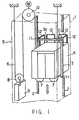
- the conventional elevator as shown in FIG. 1, is operated in an elevator shaft 1 extending vertically in the building, and includes a pair of guide rails 2 installed in the shaft 1, a cage 4 movably supported between the guide rails 2 via a cage frame 3, and a drive system 5 moving the cage 4 up and down.
- the drive system 5 is composed of cables (only one is shown) 6, two car sheaves 7, a counter weight sheave 8, a counter weight 9, and a hoisting machine 10 disposed in the upper part of the shaft 1 for driving the cables 6.
- the overhead measurements are determined by a distance between the highest object on the cage 4, that is guide shoes 11, and the lowest object on the ceiling part of the shaft 1, that is the ceiling of the shaft 1. Further, the distance from the highest object on the cage 4 to the lowest object on the ceiling of the shaft 1 can be affected by conditions of other components in the shaft 1 such as a stroke of a counter weight oil buffer (not shown), or a distance between the counter weight oil buffer and the counter weight 8.
- the railings 12 do not achieve the main object of ensuring the safety of the maintenance workers on the cage 4.
- the height Y of the railings 12 becomes higher, the overhead measurements become longer, and as a result, it becomes impossible to realize an elevator with small overhead measurements.
- one object of the present invention is to provide a novel elevator with small overhead measurements and which can ensure the safety of maintenance workers on the cage during an inspection by means of railings.
- a new and improved elevator including a cage configured to ascend and descend in an elevator shaft, and a railing member disposed on the cage along a top edge thereof and configured to be adjustable in height.
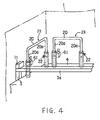
- FIG. 3 and FIG. 4 designate the same or corresponding parts throughout the several views.
- the railing members 23 are respectively formed in the shape of an inverted U and disposed at intervals on a cage 4 along the top side edges and the top back edge thereof.
- the railing member 23 disposed on the right side edge of the cage 4 is not shown, but only the railing members 23 disposed on the left side and the back side of the cage 4 are shown.
- the railing members 23 are installed on the upper surface of the cage 4 so as to expand and contract vertically.
- Each of the railing members 23 is composed of a pair of cylindrical pipes 21 standing on the cage 4 and a railing 20 having a pair of legs 20a movably inserted in the pipes 21 and extending from the upper ends thereof.
- the railing 20 is adjustable in height by inserting the legs 20a into the pipes 21 as shown in FIG. 3 and pulling the legs 20a out of the pipes 21 as shown in FIG. 4.
- the height of each pipe 21 is set such that the height Y of the railing 20 at the time the legs 20a are entirely inserted the pipes 21 becomes lower than the height X of the highest protruded object on the cage 4, typically the height of guide shoe 11, for example.
- the railing 20 is contracted to a position lower than the height X of the highest protruded object on the cage 4 at the time of normal operation of the elevator, and expanded to a higher position to ensure the safety of a maintenance worker at the time of inspection of the elevator.
- a lock device such as a bolt 22 heading to the inside of the pipe 21 is screwed on one of the upper end surfaces of the pair of pipes 21 in order to lock the expanded railing 20 at a position ensuring the safety of a maintenance worker by pushing the legs 20a with a head of the bolt 22.
- the elevator can be installed in a building without increasing the overhead measurements.
- the first embodiment can both reduce the over head measurements and ensure safety. Moreover, in the first embodiment, since the sliding railing members 23 are adopted, it is easy to design a railing height surely ensuring the safety of the maintenance worker by increasing the number of tiers of telescoping railings.
- FIG. 5 and FIG. 6 are perspective views of railing members 33 of a second embodiment of the present invention, in which folding railing members are employed instead of sliding telescoping railings.
- the railing members 33 are disposed on the cage 4 along the top side edges and the top back edge thereof. In FIGs. 5 and 6, only the railing member 33 disposed on the left side of the cage 4 is shown. The railing members 33 disposed on the right side edge and the back side edge of the cage 4 are not shown for the sake of convenience.
- Each of the railing members 33 is composed of a pair of hinge plates 31 mounted on the cage 4 so as to fold a railing 30 toward the center of the cage 4.
- the railing 30 has a pair of legs 30a which when upright have sufficient height to ensure the safety of a maintenance worker and are respectively secured to turning plates 31a of the hinge plates 31.
- the railing 30 is folded down to the center of the cage 4 to a position lower than the height of the highest object on the cage 4.
- the railing 30 is unfolded to the upright state as shown in FIG. 6 with enough height to ensure the safety of the maintenance worker.
- a lock link 32 is attached to one of the hinge plates 31 in order to maintain the upright state of the railing 30, so that the railing 30 does not fold from the upright state to the folded state as long as the lock is not released.
- folding railings of the second embodiment potentially offer the advantage of increased upright height of the railings, depending on the width and depth of the cage 4.
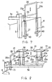
- FIG. 7 is a perspective view of one railing member of a third embodiment of the present invention, in which the railing members 23 in the first embodiment shown in FIG. 3 are modified.
- the railing members 24 of FIG. 7 are respectively formed in the shape of an inverted U and disposed at intervals along the top side edges and the top back edge of the cage 4 in the same way as the first embodiment in FIG. 3. In FIG. 7, only the railing member 24 disposed on the right side edge of the cage 4 is shown. In this embodiment, the railing members 24 are installed on side surface of the cage 4 so as to expand and contract vertically.
- Each of the railing members 24 is composed of a pair of cylindrical pipes 21 standing on the side of the cage 4 and a railing 20 having a pair of legs 20a movably inserted in the pipes 21 from the upper ends thereof.
- the railing 20 is adjustable in height by putting the legs 20a into the pipes 21 as shown in FIG. 7 and pulling the legs 20a out of the pipes 21.
- the pipes 21 are secured on the side of the cage 4 with securing members 40.
- a lock device such as a bolt 22 heading to the inside of the pipe 21 is screwed on one of the upper end surfaces of the pair of pipes 21 in order to lock the expanded railing 20 at a position ensuring the safety of a maintenance worker by pushing the legs 20a with a head of the bolt 22.
- pipes 21 of relatively long length can be employed whereby railings 20 of sufficient height can easily be implemented.
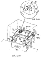
- FIG. 8 is a perspective view of railing members of a fourth embodiment of the present invention.
- the fourth embodiment modifies the first embodiment shown in FIG. 3, by adding connecting plates 50 to the components of the first embodiment.
- the adjacent railings 20 are integrated at the upper portion thereof with one of the connecting plates 50 so that all of the railings 20 can simultaneously be returned to the folding state at the time of changing the elevator from an inspection state to a normal operation state.
- all railing members 23 can be moved up and down by operating one of the railings 20.
- the railing members 23 can be prevented from colliding with the ceiling of the shaft 1 after returning the elevator to the normal operation state.
- FIG. 9 is a perspective view of railing members of a fifth embodiment of the present invention, in which an operation prohibiting device 60, which prohibits a normal operation of the elevator until the railings 20 return to a position lower than the highest object on the cage 4, is added to the fourth embodiment.
- the operation prohibiting device 60 is composed of a limit switch 61 which detects whether the railings 20 return to a proper position, and a controller 62.
- the limit switch 61 outputs a confirmation signal to the controller 62 at the time the railings 20 return to a proper position for a normal operation of the elevator.
- the controller 62 outputs a permit signal to the hoisting machine 10 to allow a normal operation of the elevator only upon receiving the confirmation signal in order. That is, the elevator can not be operated until the railings 20 return to a position lower than the highest object on the cage 4, i.e. the guide shoe 11.
- the fifth embodiment even if it is attempted to operate the elevator in a normal operation is prevented, that is, the railings 20 remain higher than the guide shoe 11, the normal operation is prevented, so that the safety of the elevator can be improved.
- This operation prohibiting device 60 can be employed with railing members individually installed on the cage 4 as described in the first embodiment, the second embodiment or the third embodiment. In this case, as shown with a double dotted chain line in FIG. 4, plural limit switches 61 are attached to respective of the railing members 23.
- FIG. 10 is a perspective view of a railing member 78 of a sixth embodiment of the present invention.
- FIG. 11 is a front view showing the railing member 78 in FIG. 10.
- a height of the railing member 78 is composed to be adjustable in height before the maintenance worker steps on the cage 4.
- the railing member 78 is composed of a pair of first railing members 70 disposed on the cage 4 along the top side edges thereof so as to be adjustable in height, and a second railing member 75 disposed on the cage 4 along the top back side of thereof so as to be adjustable in height.
- the first railing members 70 and the second railing member 75 can be raised for inspection before the maintenance worker steps on the cage 4 from an elevator depot.
- Each of the first railing members 70 is composed of a railing 71 formed in the shape of an inverted U and extending from the front side of the cage 4 to the back side.
- the railing 71 has two legs 71a mounted on stands 73 on the cage 4 via hinges 72 capable of turning toward the center of the cage 4.
- the first railing members 70 are installed on the cage 4 so as to stand upright and to fold toward the center of the cage 4 as indicated by double dotted chain lines.
- the first railing members 70 are folded and lain on top of the cage frame 3a.
- the second railing member 75 is composed of a chain 76 connected at opposite ends thereof to the back side ends of the railings 71.
- the chain 76 is disposed between the railings 71 so as to achieve a desired height when the railings 71 stand upright. That is, the chain 76 becomes tight and loose according to up and down movement of the railings 71, thereby changing its height.
- ratchets 77 are attached to respective front sides of the hinges 72 supporting the legs 71a.
- the ratchets 77 lock a turning part and a fixed part of the hinges together, thereby maintaining the upright state of the railings 71.
- knobs 77a are respectively provided at the ratchets 77 in order to release the lock state of the ratchets 77.
- the maintenance worker grabs one of the legs 71a and stands the railing 71 upright by leaning out of the elevator depot before stepping on the cage 4, and then locks the hinge 72 with the ratchet 77.
- the other railing 71 is lifted up and locked in the same way, as a result, both sides of the railings 71 are locked and kept in upright state as shown in FIG. 10 and FIG. 11.
- the maintenance worker first steps out to the elevator depot, then releases the lock state of the ratchets 77 by operating the knobs 77a and folds the railings 71 toward the center of the cage 4.
- the height of the railings 71 and the chain 76 can be set to a position ensuring the safety of the maintenance worker before stepping on the cage 4.
- the maintenance worker can step on the cage 4 after ensuring the safety, and inspect the elevator in safety.
- the overall height of the railing member 78 suitable for the safety of the maintenance worker becomes the height Y equal to the sum of the height Y1 of the stands 73 and the height Y2 of the railings 71 as shown in FIG. 11.
- the railing member 78 can be housed in a small space.
- the same railings 71 can be used though the height of the stands 73 might be changed.
- FIG. 12(a) is a perspective view of a railing member of a seventh embodiment of the present invention.
- FIG. 12(b) is a perspective view of a principal part of the railing member in FIG. 12(a).
- This embodiment modifies the sixth embodiment, substituting a folding railing member 83 for the chain 76 as the second railing member 75.
- the railing member 83 is composed of a railing 84 formed in the shape of an inverted U.
- the opposite end portions 84b of the railing 84 are formed in a crank, and pivotably supported on the cage 4 by means of a shaft bearing (not shown), thereby enabling the railing 84 to be lifted up to stand upright and to be folded toward the center of the cage 4 as shown in FIG. 12(a).
- One of the legs 71a adjacent to the railing 84 is formed in the same way as the end portion 84b. That is, one end portion 71b of the legs 71a is pivotably supported on the cage 4 as shown in FIG. 12(b) by means of a shaft bearing (not shown).
- the both end portions 84b and 71b are connected by a gear member 86 composed of two bevel gears 85.
- the railing 84 is folded together therewith.
- the railing 84 also stands. Only one railing 71 need be manipulated to achieve such operation.
- FIG. 13(a) is a top view of a railing member of an eighth embodiment of the present invention.
- FIG. 13(b) is a front view of the railing member in FIG. 13(a).
- This embodiment modifies the sixth embodiment, substituting a link railing member 91 for the chain 76 as the second railing member 75.
- the railing member 91 is composed of a pair of railings 90 pivotably connected at one of the ends thereof to respective back side ends of the railings 71, with the other ends thereof connected together.
- the railings 90 are moved downward and folded, turning at the connecting point 91a.
- a lock device 92 is added to the railing member 91 in order to keep a desired railing position and to disperse and reduce a load to be added to the railings 90.
- the lock device 92 is composed of a nut 93 welded on back side of one of the railings 90, and a bolt 94 to be screwed in the nut 93 through a hole (not shown) provided on the other railing 90 in correspondence with the location of the nut 93.
- the railings 90 are locked in a straight line by means of the nut 93 and the bolt 94.
- FIG. 14 is a front view of a railing member of a ninth embodiment of the present invention.
- This embodiment modifies the sixth embodiment, substituting a link railing member 100 for the chain 76 as the second railing member 75.
- the railing member 100 is composed of a pair of first railings 101 and 103 pivotably connected at one end of each thereof to respective back side ends of the railings 71, and a parallel railing 102 pivotably connected at opposite ends thereof to respective opposite ends of the first railings 101 and 103.
- first railings 101 and 103 pivotably connected at one end of each thereof to respective back side ends of the railings 71
- parallel railing 102 pivotably connected at opposite ends thereof to respective opposite ends of the first railings 101 and 103.
- the entire folded height H of the railing member 100 can be lowered.
- FIG. 15(a) is a top view of a railing member of a tenth embodiment of the present invention.
- FIG. 15(b) is a front view of the railing member in FIG. 15(a).
- This embodiment modifies the sixth embodiment, substituting a slide railing member 108 for the chain 76 as the second railing member 75.
- the railing member 108 is composed of a railing 106 having a pair of slit rails 105 extending between the railings 71, and a pair of cam rollers 107 attached to respective back sides of the railings 71 and guided by the rails 105.
- the railing member 108 is moved downward and folded, being guided by the cam rollers 107 and the slit rails 105.
- the slit rails 105 can be substituted for a guide rail attached to a side of the railing 106 without a slit.
- FIG. 16 is a front view of a railing member of an eleventh embodiment of the present invention.
- This embodiment modifies the sixth embodiment, substituting an elastic railing member 112 for the chain 76 as the second railing member 75.
- the railing member 112 is composed of a pair of cylinders 111 each pivotably connected at one end thereof to respective back sides of the railings 71, and an elastic member 110 connected at opposite ends thereof to inside of the cylinders 111.
- the railing member 112 is moved downward, and the elastic member 110 is contracted.
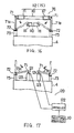
- FIG. 17 is a front view of a railing member of a twelfth embodiment of the present invention.
- This embodiment modifies the sixth embodiment in FIG. 10, adding an operation prohibiting device 120, which prohibits a normal operation of the elevator until the railings 71 return to a position lower than the highest object on the cage 4, to the sixth embodiment.
- the operation prohibiting device 120 is composed of two limit switches 121 mounted on the cage 4 via stands 123 for detecting whether the railings 71 return to a proper position, and a controller 122.
- the limit switches 121 output confirmation signals to the controller 122 at the time the railings 71 return to a proper position for a normal operation of the elevator.
- the controller 122 outputs a permit signal to the hoisting machine 10 only upon receiving both confirmation signals from each limit switch 121 in order to allow a normal operation of the elevator. That is, the elevator can not be operated until the railings 71 return to a position lower than the highest object on the cage 4.
- FIG. 18 is a front view of a railing member of a thirteenth embodiment of the present invention.
- This embodiment modifies the twelfth embodiment of FIG. 17, by mounting the limit switches 121 on the railings 71. That is, the projections 121a of the limit switches 121 are mounted on respective of the railings 71 such that the projections 121a contact stands 124 at the time the railings 71 fold down.
- the elevator can not be operated until the railings 71 return to a position lower than the highest object on the cage 4.
- FIG. 19 is a front view of a railing member of a fourteenth embodiment of the present invention.
- This embodiment modifies the twelfth embodiment in FIG. 17, substituting a switch device 125 for the limit switches 121.
- the switch device 125 is composed of a turning switch 125a installed on an upper side of one of the railings 71, and a plate 126 attached on an upper side of the other railing 71 for switching on and off the turning switch 125a by contacting the turning switch 125a.
- a turning switch 125a installed on an upper side of one of the railings 71
- a plate 126 attached on an upper side of the other railing 71 for switching on and off the turning switch 125a by contacting the turning switch 125a.
Landscapes
- Engineering & Computer Science (AREA)
- Civil Engineering (AREA)
- Mechanical Engineering (AREA)
- Structural Engineering (AREA)
- Maintenance And Inspection Apparatuses For Elevators (AREA)
- Cage And Drive Apparatuses For Elevators (AREA)
- Types And Forms Of Lifts (AREA)
Applications Claiming Priority (4)
| Application Number | Priority Date | Filing Date | Title |
|---|---|---|---|
| JP24987398 | 1998-09-03 | ||
| JP24987398 | 1998-09-03 | ||
| JP28784398 | 1998-10-09 | ||
| JP28784398A JP4245209B2 (ja) | 1998-09-03 | 1998-10-09 | エレべーター |
Publications (3)
| Publication Number | Publication Date |
|---|---|
| EP0985628A2 true EP0985628A2 (de) | 2000-03-15 |
| EP0985628A3 EP0985628A3 (de) | 2003-10-15 |
| EP0985628B1 EP0985628B1 (de) | 2008-04-16 |
Family
ID=26539533
Family Applications (1)
| Application Number | Title | Priority Date | Filing Date |
|---|---|---|---|
| EP99116859A Expired - Lifetime EP0985628B1 (de) | 1998-09-03 | 1999-09-03 | Aufzug mit verstellbaren Geländernoberseiten |
Country Status (8)
| Country | Link |
|---|---|
| US (1) | US6543584B1 (de) |
| EP (1) | EP0985628B1 (de) |
| JP (1) | JP4245209B2 (de) |
| KR (1) | KR100399425B1 (de) |
| CN (1) | CN1120798C (de) |
| DE (1) | DE69938524T2 (de) |
| MY (1) | MY126540A (de) |
| TW (1) | TW446680B (de) |
Cited By (15)
| Publication number | Priority date | Publication date | Assignee | Title |
|---|---|---|---|---|
| WO2002085773A1 (fr) | 2001-04-17 | 2002-10-31 | Mitsubishi Denki Kabushiki Kaisha | Cage d'ascenseur et ascenseur |
| WO2003018459A1 (en) * | 2001-08-27 | 2003-03-06 | Otis Elevator Company | Safety apparatus for maintenance of elevator systems from top of the car |
| WO2003020629A1 (fr) | 2001-08-28 | 2003-03-13 | Mitsubishi Denki Kabushiki Kaisha | Cabine et monte-charge |
| WO2003095350A1 (en) * | 2002-05-09 | 2003-11-20 | Otis Elevator Company | Safety fence at upper part of cab |
| WO2004000713A1 (en) * | 2002-06-20 | 2003-12-31 | Otis Elevator Company | Safety top balustrade for a car of a machine room-less elevator |
| FR2866665A1 (fr) * | 2004-02-24 | 2005-08-26 | Juan Perea | Dispositif de securite du type garde corps, systeme d'ascenseur comprenant un tel dispositif, et procede de mise en securite d'une installation |
| WO2006087598A1 (en) * | 2005-02-18 | 2006-08-24 | Otis Elevator Company | Roof railing for an elevator car adapted to be collapsed with a handle actuating all sides at the same time |
| FR2891820A1 (fr) * | 2005-10-07 | 2007-04-13 | Thyssenkrupp Elevator Mfg F | Systeme d'ascenseur comprenant un dispositif de securite |
| NL1030867C2 (nl) * | 2006-01-06 | 2007-07-09 | Melker B V De | Veiligheidsconstructies voor een liftkooi. |
| WO2008004022A1 (en) * | 2006-06-30 | 2008-01-10 | Otis Elevator Company | Elevator having a shallow pit and/or a low overhead |
| US7322445B2 (en) | 2003-03-31 | 2008-01-29 | Inventio Ag | Stop bar for creating a temporary safety space within an elevator hoistway |
| EP2295363A1 (de) * | 2002-05-01 | 2011-03-16 | Mitsubishi Denki Kabushiki Kaisha | An Kabine angebrachter Handlauf für Aufzug |
| US8136637B2 (en) | 2006-06-30 | 2012-03-20 | Otis Elevator Company | Safety device for securing minimum spaces at the top or bottom of an elevator shaft being inspected, and elevator having such safety devices |
| WO2018178285A1 (de) | 2017-03-30 | 2018-10-04 | Inventio Ag | Aufzug |
| US11174124B2 (en) | 2016-11-15 | 2021-11-16 | Inventio Ag | Elevator car |
Families Citing this family (48)
| Publication number | Priority date | Publication date | Assignee | Title |
|---|---|---|---|---|
| EP1346942B1 (de) * | 2000-12-28 | 2008-08-27 | Mitsubishi Denki Kabushiki Kaisha | Oberes kabinengeländer für aufzug |
| JP4684445B2 (ja) * | 2001-03-23 | 2011-05-18 | 三菱電機株式会社 | エレベーターのかご装置 |
| CN1283543C (zh) * | 2002-03-07 | 2006-11-08 | 三菱电机株式会社 | 电梯的轿厢上扶手装置 |
| US20050230194A1 (en) * | 2002-05-09 | 2005-10-20 | Ryushu Nakamura | Safety fence at upper part of cab |
| US6830127B2 (en) * | 2002-08-29 | 2004-12-14 | Robert Aaron Johnson | Pipeline construction safety platform |
| US20040104382A1 (en) * | 2002-12-02 | 2004-06-03 | Collins Douglas R. | Safety railing system for roof access hatch |
| ES2383009T3 (es) * | 2003-09-15 | 2012-06-15 | Otis Elevator Company | Dispositivos de seguridad para inspección de ascensores |
| US20050224299A1 (en) * | 2004-04-13 | 2005-10-13 | Soemardjan San A | Elevator recessed car top for refuge area |
| JP4627430B2 (ja) * | 2004-10-21 | 2011-02-09 | 三菱電機株式会社 | エレベータかごの手摺装置 |
| WO2008041332A1 (fr) * | 2006-10-04 | 2008-04-10 | Mitsubishi Electric Corporation | Système d'ascenseur |
| US8833520B2 (en) * | 2006-12-15 | 2014-09-16 | C. & V. Engineering Company Pty Ltd | Fall safety barrier |
| JP2008174337A (ja) * | 2007-01-17 | 2008-07-31 | Mitsubishi Electric Corp | かご上手摺装置 |
| JP4944628B2 (ja) * | 2007-01-26 | 2012-06-06 | パナソニック ホームエレベーター株式会社 | エレベータ装置の作業台の手摺り構造 |
| JP2008285266A (ja) * | 2007-05-16 | 2008-11-27 | Toshiba Elevator Co Ltd | エレベータかご上作業用安全装置 |
| KR100907140B1 (ko) | 2007-07-04 | 2009-07-09 | 미쓰비시덴키 가부시키가이샤 | 엘리베이터 장치 |
| JP5360645B2 (ja) * | 2008-07-23 | 2013-12-04 | 日本ビソー株式会社 | 折り畳み式作業用ゴンドラ |
| JP4836286B2 (ja) * | 2008-10-21 | 2011-12-14 | 東芝エレベータ株式会社 | エレベータ装置 |
| CA2718454A1 (en) * | 2009-10-20 | 2011-04-20 | Kirk B. Gregus | Elevator work deck |
| WO2012175394A1 (de) * | 2011-06-22 | 2012-12-27 | Inventio Ag | Feuerwehraufzug |
| KR20140082972A (ko) * | 2011-10-13 | 2014-07-03 | 인벤티오 아게 | 승강기 |
| US9764925B2 (en) | 2011-12-21 | 2017-09-19 | Otis Elevator Company | Elevator system including a car stop for maintaining overhead clearance |
| JP5923607B2 (ja) * | 2012-07-20 | 2016-05-24 | 株式会社日立製作所 | エレベーター装置 |
| CN103011033B (zh) * | 2012-12-21 | 2015-08-12 | 中联重科股份有限公司 | 高空平台系统及包含该高空平台系统的工程机械 |
| JP5778722B2 (ja) * | 2013-07-23 | 2015-09-16 | オーチス エレベータ カンパニーOtis Elevator Company | 浅いピットおよび/または低いオーバヘッドを備えたエレベータ |
| KR101432643B1 (ko) | 2013-12-31 | 2014-08-22 | 주식회사 삼덕티엘에스 | 물류운반용 높이조절식 컨테이너형 안전곤돌라 |
| JP6145078B2 (ja) * | 2014-04-23 | 2017-06-07 | 株式会社シィップ | 昇降台装置 |
| DE112015005891T5 (de) * | 2015-01-05 | 2017-09-21 | Mitsubishi Electric Corporation | Aufzugsvorrichtung |
| EP3247664B1 (de) * | 2015-01-20 | 2019-10-23 | Inventio AG | Aufzug |
| WO2016135922A1 (ja) * | 2015-02-26 | 2016-09-01 | 三菱電機株式会社 | エレベータ装置 |
| DE102015211488A1 (de) | 2015-06-22 | 2016-12-22 | Thyssenkrupp Ag | Sicherheitseinrichtung einer Aufzugsanlage |
| DE112015006696T5 (de) * | 2015-07-15 | 2018-03-29 | Mitsubishi Electric Corporation | Aufzugsvorrichtung |
| US10233054B2 (en) * | 2015-07-23 | 2019-03-19 | Mitsubishi Electric Corporation | Elevator car upper handrail apparatus |
| WO2017055387A1 (de) * | 2015-09-30 | 2017-04-06 | Inventio Ag | Aufzugsanlage |
| WO2017102966A1 (de) * | 2015-12-18 | 2017-06-22 | Inventio Ag | Aufzugskabine mit einer klappbaren balustrade sowie steuerungsvorrichtung für eine aufzuganlage mit einer solchen aufzugskabine |
| WO2018011976A1 (ja) * | 2016-07-15 | 2018-01-18 | 三菱電機株式会社 | エレベータ装置 |
| WO2018073896A1 (ja) * | 2016-10-18 | 2018-04-26 | 三菱電機株式会社 | エレベータのかご上手摺装置 |
| CN109843774B (zh) * | 2016-10-27 | 2020-12-11 | 三菱电机株式会社 | 电梯的轿厢上扶手装置 |
| DE102016121742A1 (de) * | 2016-11-14 | 2018-05-17 | Thyssenkrupp Ag | Fahrkorb für ein Aufzugsystem |
| CN108557602A (zh) * | 2018-06-27 | 2018-09-21 | 通力电梯有限公司 | 用于电梯的安全防护装置和包括该安全防护装置的电梯 |
| KR20200025780A (ko) | 2018-08-31 | 2020-03-10 | 이금기 | 엘리베이터 상부용 안전난간 |
| CN111362085B (zh) * | 2018-12-26 | 2022-12-20 | 奥的斯电梯公司 | 栏杆组件、轿厢和电梯 |
| JP7135902B2 (ja) * | 2019-02-01 | 2022-09-13 | 三菱電機株式会社 | エレベーターかご天井上巾木装置 |
| WO2021121904A1 (en) * | 2019-12-20 | 2021-06-24 | Inventio Ag | Elevator car pivotable balustrade and maintenance method for an elevator |
| CN111302191A (zh) * | 2020-03-31 | 2020-06-19 | 瑞普兰德电梯有限公司 | 一种电梯轿厢内安全防护围栏 |
| KR102205714B1 (ko) * | 2020-08-10 | 2021-01-21 | 아세아시멘트(주) | 절첩기능을 갖는 사이로장치용 핸드레일 및 이를 포함하는 사이로장치 |
| CN114074884A (zh) * | 2020-08-13 | 2022-02-22 | 奥的斯电梯公司 | 顶部扩展部及其操作方法、电梯轿厢组件和电梯系统 |
| EP4005961A1 (de) | 2020-11-30 | 2022-06-01 | Inventio AG | Aufzugskabine mit einer balustrade |
| CN113682921A (zh) * | 2021-08-24 | 2021-11-23 | 崔晓江 | 一种简易井道平台 |
Citations (2)
| Publication number | Priority date | Publication date | Assignee | Title |
|---|---|---|---|---|
| GB2158038A (en) | 1984-04-27 | 1985-11-06 | Afd Engineering | Lift car top barrier |
| JPH01281281A (ja) | 1988-05-06 | 1989-11-13 | Mitsubishi Electric Corp | エレベーターのかご上安全さく |
Family Cites Families (8)
| Publication number | Priority date | Publication date | Assignee | Title |
|---|---|---|---|---|
| US3878916A (en) * | 1973-02-07 | 1975-04-22 | Jr Gerome R White | Rack and pinion drive counterbalanced hoist systems |
| JPH0649577Y2 (ja) * | 1987-11-27 | 1994-12-14 | 株式会社日立ビルシステムサービス | エレベータの保守運転装置 |
| JPH0625471B2 (ja) * | 1989-09-28 | 1994-04-06 | 株式会社竹中工務店 | 折り畳み足場 |
| JPH04292386A (ja) * | 1991-03-20 | 1992-10-16 | Toshiba Corp | 油圧エレベータかごの安全柵 |
| JPH08133617A (ja) * | 1994-11-02 | 1996-05-28 | Mitsubishi Denki Bill Techno Service Kk | エレベーターかご室上保守装置 |
| JP2001058774A (ja) * | 1999-08-18 | 2001-03-06 | Hitachi Building Systems Co Ltd | エレベータ |
| JP2002003113A (ja) * | 2000-06-15 | 2002-01-09 | Hitachi Building Systems Co Ltd | エレベーターのかご上保守運転装置 |
| JP2002020062A (ja) * | 2000-07-07 | 2002-01-23 | Mitsubishi Electric Corp | エレベーターかご室装置 |
-
1998
- 1998-10-09 JP JP28784398A patent/JP4245209B2/ja not_active Expired - Fee Related
-
1999
- 1999-08-27 TW TW088114754A patent/TW446680B/zh not_active IP Right Cessation
- 1999-08-30 MY MYPI99003734A patent/MY126540A/en unknown
- 1999-09-01 KR KR10-1999-0036869A patent/KR100399425B1/ko not_active IP Right Cessation
- 1999-09-02 CN CN99118960A patent/CN1120798C/zh not_active Expired - Fee Related
- 1999-09-03 EP EP99116859A patent/EP0985628B1/de not_active Expired - Lifetime
- 1999-09-03 US US09/389,473 patent/US6543584B1/en not_active Expired - Fee Related
- 1999-09-03 DE DE69938524T patent/DE69938524T2/de not_active Expired - Lifetime
Patent Citations (2)
| Publication number | Priority date | Publication date | Assignee | Title |
|---|---|---|---|---|
| GB2158038A (en) | 1984-04-27 | 1985-11-06 | Afd Engineering | Lift car top barrier |
| JPH01281281A (ja) | 1988-05-06 | 1989-11-13 | Mitsubishi Electric Corp | エレベーターのかご上安全さく |
Non-Patent Citations (1)
| Title |
|---|
| PATENT ABSTRACTS OF JAPAN vol. 014, no. 056 (M - 0929) 31 January 1990 (1990-01-31) |
Cited By (29)
| Publication number | Priority date | Publication date | Assignee | Title |
|---|---|---|---|---|
| EP1386876A4 (de) * | 2001-04-17 | 2004-06-23 | Mitsubishi Electric Corp | Aufzugskäfig und aufzug |
| WO2002085773A1 (fr) | 2001-04-17 | 2002-10-31 | Mitsubishi Denki Kabushiki Kaisha | Cage d'ascenseur et ascenseur |
| EP1386876A1 (de) * | 2001-04-17 | 2004-02-04 | Mitsubishi Denki Kabushiki Kaisha | Aufzugskäfig und aufzug |
| WO2003018459A1 (en) * | 2001-08-27 | 2003-03-06 | Otis Elevator Company | Safety apparatus for maintenance of elevator systems from top of the car |
| WO2003020629A1 (fr) | 2001-08-28 | 2003-03-13 | Mitsubishi Denki Kabushiki Kaisha | Cabine et monte-charge |
| EP1422185A4 (de) * | 2001-08-28 | 2010-06-23 | Mitsubishi Electric Corp | Käfig und aufzug |
| EP1422185A1 (de) * | 2001-08-28 | 2004-05-26 | Mitsubishi Denki Kabushiki Kaisha | Käfig und aufzug |
| EP2295363A1 (de) * | 2002-05-01 | 2011-03-16 | Mitsubishi Denki Kabushiki Kaisha | An Kabine angebrachter Handlauf für Aufzug |
| WO2003095350A1 (en) * | 2002-05-09 | 2003-11-20 | Otis Elevator Company | Safety fence at upper part of cab |
| JP2005532966A (ja) * | 2002-06-20 | 2005-11-04 | オーチス エレベータ カンパニー | 機械室レス型エレベータのかご用の上部安全柵 |
| US7140473B2 (en) | 2002-06-20 | 2006-11-28 | Otis Elevator Company | Safety top balustrade for a car of a machine room-less elevator |
| CN1309649C (zh) * | 2002-06-20 | 2007-04-11 | 奥蒂斯电梯公司 | 用于无机房电梯的轿厢的顶部安全扶栏 |
| WO2004000713A1 (en) * | 2002-06-20 | 2003-12-31 | Otis Elevator Company | Safety top balustrade for a car of a machine room-less elevator |
| US7886879B2 (en) | 2003-03-31 | 2011-02-15 | Inventio Ag | Method for creating temporary safety space within an elevator hoistway |
| US7322445B2 (en) | 2003-03-31 | 2008-01-29 | Inventio Ag | Stop bar for creating a temporary safety space within an elevator hoistway |
| FR2866665A1 (fr) * | 2004-02-24 | 2005-08-26 | Juan Perea | Dispositif de securite du type garde corps, systeme d'ascenseur comprenant un tel dispositif, et procede de mise en securite d'une installation |
| US7510056B2 (en) | 2005-02-18 | 2009-03-31 | Otis Elevator Company | Roof railing for an elevator car adapted to be collapsed with a handle actuating all sides at the same time |
| WO2006087598A1 (en) * | 2005-02-18 | 2006-08-24 | Otis Elevator Company | Roof railing for an elevator car adapted to be collapsed with a handle actuating all sides at the same time |
| FR2891820A1 (fr) * | 2005-10-07 | 2007-04-13 | Thyssenkrupp Elevator Mfg F | Systeme d'ascenseur comprenant un dispositif de securite |
| NL1030867C2 (nl) * | 2006-01-06 | 2007-07-09 | Melker B V De | Veiligheidsconstructies voor een liftkooi. |
| EP2033927A1 (de) * | 2006-06-30 | 2009-03-11 | Otis Elevator Company | Aufzug mit einem flachen Schacht und/oder einem geringen Kopfraum |
| WO2008004022A1 (en) * | 2006-06-30 | 2008-01-10 | Otis Elevator Company | Elevator having a shallow pit and/or a low overhead |
| US8136637B2 (en) | 2006-06-30 | 2012-03-20 | Otis Elevator Company | Safety device for securing minimum spaces at the top or bottom of an elevator shaft being inspected, and elevator having such safety devices |
| US8162108B2 (en) | 2006-06-30 | 2012-04-24 | Otis Elevator Company | Elevator having a limit switch for controlling power to the drive system as an elevator car approaches a shallow pit or a low overhead |
| US8365870B2 (en) | 2006-06-30 | 2013-02-05 | Otis Elevator Company | Foldable handrail and safety switch arrangement on top of an elevator car |
| CN101472830B (zh) * | 2006-06-30 | 2013-07-17 | 奥蒂斯电梯公司 | 具有浅井坑和/或低顶盖的电梯 |
| US11174124B2 (en) | 2016-11-15 | 2021-11-16 | Inventio Ag | Elevator car |
| EP3541734B1 (de) | 2016-11-15 | 2023-03-22 | Inventio Ag | Aufzugskabine |
| WO2018178285A1 (de) | 2017-03-30 | 2018-10-04 | Inventio Ag | Aufzug |
Also Published As
| Publication number | Publication date |
|---|---|
| KR20000022841A (ko) | 2000-04-25 |
| KR100399425B1 (ko) | 2003-09-29 |
| JP2000143125A (ja) | 2000-05-23 |
| JP4245209B2 (ja) | 2009-03-25 |
| MY126540A (en) | 2006-10-31 |
| US6543584B1 (en) | 2003-04-08 |
| DE69938524T2 (de) | 2009-06-10 |
| EP0985628B1 (de) | 2008-04-16 |
| CN1246437A (zh) | 2000-03-08 |
| DE69938524D1 (de) | 2008-05-29 |
| EP0985628A3 (de) | 2003-10-15 |
| TW446680B (en) | 2001-07-21 |
| CN1120798C (zh) | 2003-09-10 |
Similar Documents
| Publication | Publication Date | Title |
|---|---|---|
| US6543584B1 (en) | Elevator with adjustable top edge railing members | |
| CN110194405B (zh) | 电梯轿厢和包括电梯轿厢的电梯系统 | |
| EP1224142B1 (de) | Seilaufzug | |
| US11192754B2 (en) | Elevator arrangement and elevator | |
| CA1146096A (en) | Modular elevator car | |
| JP2007063021A (ja) | 保守プラットフォームを有するエレベータケージ、およびエレベータ設備の保守のための方法 | |
| CN103167998A (zh) | 电梯的控制盘 | |
| KR20070037995A (ko) | 승강실 및 승강로에 승강실의 지지 수단을 설치하는 방법 | |
| JP5217073B2 (ja) | 乗りかご及びエレベータ装置 | |
| CN101066733A (zh) | 折叠式检修平台 | |
| EP1509473B1 (de) | Sicherheitsumzäunung auf aufzugskabine | |
| CN111634786A (zh) | 用于电梯轿厢的工作平台 | |
| US11198594B2 (en) | Elevator car apron | |
| KR20200025780A (ko) | 엘리베이터 상부용 안전난간 | |
| CN102232050A (zh) | 包括支承于电梯机器支承件上的控制电子器件的电梯系统 | |
| US20050230194A1 (en) | Safety fence at upper part of cab | |
| EP1481936B1 (de) | Aufzugskabine mit einem darauf angeordneten handlauf | |
| EP0687644A2 (de) | Aufhängevorrichtung eines hydraulischen Aufzugs | |
| EP3599210B1 (de) | Aufzugskabinenschürze | |
| US10689232B2 (en) | Floor covering of a passenger conveyor | |
| JP4251921B2 (ja) | エレベーター装置 | |
| EP1329411B1 (de) | Aufzugsvorrichtung | |
| JP2004244188A (ja) | エレベータかご | |
| JP7318882B2 (ja) | テーブルリフト | |
| KR20050096908A (ko) | 엘리베이터의 작업 발판 장치 |
Legal Events
| Date | Code | Title | Description |
|---|---|---|---|
| PUAI | Public reference made under article 153(3) epc to a published international application that has entered the european phase |
Free format text: ORIGINAL CODE: 0009012 |
|
| 17P | Request for examination filed |
Effective date: 19990903 |
|
| AK | Designated contracting states |
Kind code of ref document: A2 Designated state(s): AT BE CH CY DE DK ES FI FR GB GR IE IT LI LU MC NL PT SE |
|
| AX | Request for extension of the european patent |
Free format text: AL;LT;LV;MK;RO;SI |
|
| PUAL | Search report despatched |
Free format text: ORIGINAL CODE: 0009013 |
|
| AK | Designated contracting states |
Kind code of ref document: A3 Designated state(s): AT BE CH CY DE DK ES FI FR GB GR IE IT LI LU MC NL PT SE |
|
| AX | Request for extension of the european patent |
Extension state: AL LT LV MK RO SI |
|
| RIC1 | Information provided on ipc code assigned before grant |
Ipc: 7B 66B 11/02 B Ipc: 7B 66B 5/00 B Ipc: 7B 66B 13/24 A |
|
| TPAC | Observations filed by third parties |
Free format text: ORIGINAL CODE: EPIDOSNTIPA |
|
| AKX | Designation fees paid |
Designated state(s): CH DE FI LI |
|
| GRAP | Despatch of communication of intention to grant a patent |
Free format text: ORIGINAL CODE: EPIDOSNIGR1 |
|
| 17Q | First examination report despatched |
Effective date: 20070615 |
|
| GRAS | Grant fee paid |
Free format text: ORIGINAL CODE: EPIDOSNIGR3 |
|
| GRAA | (expected) grant |
Free format text: ORIGINAL CODE: 0009210 |
|
| AK | Designated contracting states |
Kind code of ref document: B1 Designated state(s): CH DE FI LI |
|
| REG | Reference to a national code |
Ref country code: CH Ref legal event code: EP |
|
| REF | Corresponds to: |
Ref document number: 69938524 Country of ref document: DE Date of ref document: 20080529 Kind code of ref document: P |
|
| REG | Reference to a national code |
Ref country code: CH Ref legal event code: NV |
|
| PLBE | No opposition filed within time limit |
Free format text: ORIGINAL CODE: 0009261 |
|
| STAA | Information on the status of an ep patent application or granted ep patent |
Free format text: STATUS: NO OPPOSITION FILED WITHIN TIME LIMIT |
|
| 26N | No opposition filed |
Effective date: 20090119 |
|
| PGFP | Annual fee paid to national office [announced via postgrant information from national office to epo] |
Ref country code: CH Payment date: 20110913 Year of fee payment: 13 |
|
| PGFP | Annual fee paid to national office [announced via postgrant information from national office to epo] |
Ref country code: DE Payment date: 20110831 Year of fee payment: 13 Ref country code: FI Payment date: 20110912 Year of fee payment: 13 |
|
| PG25 | Lapsed in a contracting state [announced via postgrant information from national office to epo] |
Ref country code: FI Free format text: LAPSE BECAUSE OF NON-PAYMENT OF DUE FEES Effective date: 20120903 |
|
| REG | Reference to a national code |
Ref country code: CH Ref legal event code: PL |
|
| PG25 | Lapsed in a contracting state [announced via postgrant information from national office to epo] |
Ref country code: LI Free format text: LAPSE BECAUSE OF NON-PAYMENT OF DUE FEES Effective date: 20120930 Ref country code: CH Free format text: LAPSE BECAUSE OF NON-PAYMENT OF DUE FEES Effective date: 20120930 Ref country code: DE Free format text: LAPSE BECAUSE OF NON-PAYMENT OF DUE FEES Effective date: 20130403 |
|
| REG | Reference to a national code |
Ref country code: DE Ref legal event code: R119 Ref document number: 69938524 Country of ref document: DE Effective date: 20130403 |