EP0985628A2 - Elevator with adjustable top edge railing members - Google Patents
Elevator with adjustable top edge railing members Download PDFInfo
- Publication number
- EP0985628A2 EP0985628A2 EP99116859A EP99116859A EP0985628A2 EP 0985628 A2 EP0985628 A2 EP 0985628A2 EP 99116859 A EP99116859 A EP 99116859A EP 99116859 A EP99116859 A EP 99116859A EP 0985628 A2 EP0985628 A2 EP 0985628A2
- Authority
- EP
- European Patent Office
- Prior art keywords
- railing
- elevator
- cage
- members
- recited
- Prior art date
- Legal status (The legal status is an assumption and is not a legal conclusion. Google has not performed a legal analysis and makes no representation as to the accuracy of the status listed.)
- Granted
Links
Images


Classifications
-
- B—PERFORMING OPERATIONS; TRANSPORTING
- B66—HOISTING; LIFTING; HAULING
- B66B—ELEVATORS; ESCALATORS OR MOVING WALKWAYS
- B66B11/00—Main component parts of lifts in, or associated with, buildings or other structures
-
- B—PERFORMING OPERATIONS; TRANSPORTING
- B66—HOISTING; LIFTING; HAULING
- B66B—ELEVATORS; ESCALATORS OR MOVING WALKWAYS
- B66B5/00—Applications of checking, fault-correcting, or safety devices in elevators
- B66B5/0043—Devices enhancing safety during maintenance
- B66B5/005—Safety of maintenance personnel
- B66B5/0081—Safety of maintenance personnel by preventing falling by means of safety fences or handrails, being operable or not, mounted on top of the elevator car
-
- B—PERFORMING OPERATIONS; TRANSPORTING
- B66—HOISTING; LIFTING; HAULING
- B66B—ELEVATORS; ESCALATORS OR MOVING WALKWAYS
- B66B11/00—Main component parts of lifts in, or associated with, buildings or other structures
- B66B11/02—Cages, i.e. cars
Abstract
Description
- This application claims benefit of priority to Japanese Patent Applications No. JP10-249873 filed September 3, 1998 and No. JP10-287843 filed October 9, 1998, the entire contents of which are incorporated by reference herein.
- The present invention relates to an elevator with improved railings provided on an upper side of a passenger cage along the top edges thereof.
- In general, elevators have been installed in a high rise building so that residents or the like can easily get to the desired upper or lower floors.
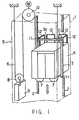
- The conventional elevator, as shown in FIG. 1, is operated in an elevator shaft 1 extending vertically in the building, and includes a pair of guide rails 2 installed in the shaft 1, a
cage 4 movably supported between the guide rails 2 via acage frame 3, and adrive system 5 moving thecage 4 up and down. Thedrive system 5 is composed of cables (only one is shown) 6, twocar sheaves 7, acounter weight sheave 8, a counter weight 9, and a hoistingmachine 10 disposed in the upper part of the shaft 1 for driving the cables 6. - In this type of elevator where the hoisting
machine 10 is disposed in the upper part of the shaft 1, thereby dispensing with a machine room located right above the shaft 1 in which a hoisting machine, a control panel and the like is conventionally installed, it is especially required to reduce the overhead measurements at the installation of the elevator so that the building space other than the shaft 1 can be used effectively. (The overhead measurements refer to a distance between a floor of thecage 4 and a ceiling of the shaft 1 at the time thecage 4 stops at the upper most floor.) - Practically speaking, the overhead measurements are determined by a distance between the highest object on the
cage 4, that isguide shoes 11, and the lowest object on the ceiling part of the shaft 1, that is the ceiling of the shaft 1. Further, the distance from the highest object on thecage 4 to the lowest object on the ceiling of the shaft 1 can be affected by conditions of other components in the shaft 1 such as a stroke of a counter weight oil buffer (not shown), or a distance between the counter weight oil buffer and thecounter weight 8. - Thus, to realize an elevator with small overhead measurements, it is necessary to reduce a distance between the highest object on the
cage 4 and the ceiling of the shaft 1. - Furthermore, elevators are required to be inspected periodically, and on such occasions, maintenance workers sometimes inspect the elevators riding on the upper side of the
cage 4. To ensure the safety of the maintenance workers, in general,railings 12 are provided on the upper side of thecage 4 along the side edges and back edge thereof. To realize an elevator with small overhead measurements, the height Y ofrailings 12 has to be lower than the height X of the highest object on thecage 4, i.e. theguide shoe 11. - However, if the height Y is lower than the height X, the
railings 12 do not achieve the main object of ensuring the safety of the maintenance workers on thecage 4. On the other hand, if the height Y of therailings 12 becomes higher, the overhead measurements become longer, and as a result, it becomes impossible to realize an elevator with small overhead measurements. - Accordingly, one object of the present invention is to provide a novel elevator with small overhead measurements and which can ensure the safety of maintenance workers on the cage during an inspection by means of railings.
- This and other objects are achieved according to the present invention by providing a new and improved elevator including a cage configured to ascend and descend in an elevator shaft, and a railing member disposed on the cage along a top edge thereof and configured to be adjustable in height.
- A more complete appreciation of the invention and many of the attendant advantages thereof will be readily obtained as the same becomes better understood by reference to the following detailed description when considered in connection with the accompanying drawings, wherein:
- FIG. 1 is a schematic perspective view showing a conventional traction type elevator;
- FIG. 2 is a perspective view of railings in FIG. 1;
- FIG. 3 is a perspective view showing railing members of a first embodiment of the present invention in a contracted state;
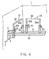
- FIG. 4 is another perspective view showing railing members of the first embodiment of the present invention in an expanded state;
- FIG. 5 is a perspective view of railing member of a second embodiment of the present invention in a collapsed state;
- FIG. 6 is a perspective view of railing member of a second embodiment of the present invention in an upright state;
- FIG. 7 is a perspective view of one railing member of a third embodiment of the present invention;
- FIG. 8 is a perspective view of railing members of a fourth embodiment of the present invention;
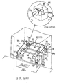
- FIG. 9 is a perspective view of railing members of a fifth embodiment of the present invention;
- FIG. 10 is a perspective view of a railing member of a sixth embodiment of the present invention;
- FIG. 11 is a front view showing the railing member in FIG. 10;
- FIG. 12(a) is a perspective view of a railing member of a seventh embodiment of the present invention;
- FIG. 12(b) is a perspective view of the principal part of the railing member in FIG. 12(a);
- FIG. 13(a) is a top view of a railing member of an eighth embodiment of the present invention;
- FIG. 13(b) is a front view of the railing member in FIG. 13(a);
- FIG. 14 is a front view of a railing member of a ninth embodiment of the present invention;
- FIG. 15(a) is a top view of a railing member of a tenth embodiment of the present invention;
- FIG. 15(b) is a front view of the railing member in FIG. 15(a);
- FIG. 16 is a front view of a railing member of an eleventh embodiment of the present invention;
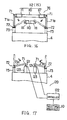
- FIG. 17 is a front view of a railing member of a twelfth embodiment of the present invention;;
- FIG. 18 is a front view of a railing member of a thirteenth embodiment of the present invention; and
- FIG. 19 is a front view of a railing member of a fourteenth embodiment of the present invention.
-
- Referring now to the drawings, where like reference numerals designate the same or corresponding parts throughout the several views, next described is a first embodiment of the present invention shown in FIG. 3 and FIG. 4.
- In this embodiment, since every component of the elevator other than
railings 12 in FIG. 1 is the same structure as FIG. 1, there will be described only components of improved railings. - As shown in FIGs. 3 and 4, the
railing members 23 are respectively formed in the shape of an inverted U and disposed at intervals on acage 4 along the top side edges and the top back edge thereof. In FIG. 3, therailing member 23 disposed on the right side edge of thecage 4 is not shown, but only therailing members 23 disposed on the left side and the back side of thecage 4 are shown. - The
railing members 23 are installed on the upper surface of thecage 4 so as to expand and contract vertically. - Each of the
railing members 23 is composed of a pair ofcylindrical pipes 21 standing on thecage 4 and arailing 20 having a pair oflegs 20a movably inserted in thepipes 21 and extending from the upper ends thereof. Therailing 20 is adjustable in height by inserting thelegs 20a into thepipes 21 as shown in FIG. 3 and pulling thelegs 20a out of thepipes 21 as shown in FIG. 4. The height of eachpipe 21 is set such that the height Y of therailing 20 at the time thelegs 20a are entirely inserted thepipes 21 becomes lower than the height X of the highest protruded object on thecage 4, typically the height ofguide shoe 11, for example. Thus, therailing 20 is contracted to a position lower than the height X of the highest protruded object on thecage 4 at the time of normal operation of the elevator, and expanded to a higher position to ensure the safety of a maintenance worker at the time of inspection of the elevator. - Further, a lock device such as a
bolt 22 heading to the inside of thepipe 21 is screwed on one of the upper end surfaces of the pair ofpipes 21 in order to lock the expandedrailing 20 at a position ensuring the safety of a maintenance worker by pushing thelegs 20a with a head of thebolt 22. - According to the
railing members 23 described above, since thelegs 20a are entirely put into thepipes 21 as shown in FIG. 3 and therailings 20 is collapsed at the time of a normal operation of the elevator, the elevator can be installed in a building without increasing the overhead measurements. - Further, in case that a maintenance worker is inspecting the elevator riding on the
cage 4, since thelegs 20a are pulled out of thepipes 21 and locked at a high position ensuring the safety of the maintenance worker by screwing thebolt 22, the maintenance work can be performed securely. - Thus, the first embodiment can both reduce the over head measurements and ensure safety. Moreover, in the first embodiment, since the sliding
railing members 23 are adopted, it is easy to design a railing height surely ensuring the safety of the maintenance worker by increasing the number of tiers of telescoping railings. - FIG. 5 and FIG. 6 are perspective views of
railing members 33 of a second embodiment of the present invention, in which folding railing members are employed instead of sliding telescoping railings. Therailing members 33 are disposed on thecage 4 along the top side edges and the top back edge thereof. In FIGs. 5 and 6, only therailing member 33 disposed on the left side of thecage 4 is shown. Therailing members 33 disposed on the right side edge and the back side edge of thecage 4 are not shown for the sake of convenience. - Each of the
railing members 33 is composed of a pair ofhinge plates 31 mounted on thecage 4 so as to fold arailing 30 toward the center of thecage 4. Therailing 30 has a pair oflegs 30a which when upright have sufficient height to ensure the safety of a maintenance worker and are respectively secured to turningplates 31a of thehinge plates 31. In case of a normal operation of the elevator, as shown in FIG. 5, therailing 30 is folded down to the center of thecage 4 to a position lower than the height of the highest object on thecage 4. When the maintenance worker inspects the elevator while riding on thecage 4, therailing 30 is unfolded to the upright state as shown in FIG. 6 with enough height to ensure the safety of the maintenance worker. Further, alock link 32 is attached to one of thehinge plates 31 in order to maintain the upright state of therailing 30, so that therailing 30 does not fold from the upright state to the folded state as long as the lock is not released. - According to the
railing members 33 described above, the same effects as the first embodiment can be achieved. Moreover, folding railings of the second embodiment potentially offer the advantage of increased upright height of the railings, depending on the width and depth of thecage 4. - FIG. 7 is a perspective view of one railing member of a third embodiment of the present invention, in which the
railing members 23 in the first embodiment shown in FIG. 3 are modified. - The
railing members 24 of FIG. 7 are respectively formed in the shape of an inverted U and disposed at intervals along the top side edges and the top back edge of thecage 4 in the same way as the first embodiment in FIG. 3. In FIG. 7, only therailing member 24 disposed on the right side edge of thecage 4 is shown. In this embodiment, therailing members 24 are installed on side surface of thecage 4 so as to expand and contract vertically. - Each of the
railing members 24 is composed of a pair ofcylindrical pipes 21 standing on the side of thecage 4 and arailing 20 having a pair oflegs 20a movably inserted in thepipes 21 from the upper ends thereof. Therailing 20 is adjustable in height by putting thelegs 20a into thepipes 21 as shown in FIG. 7 and pulling thelegs 20a out of thepipes 21. Thepipes 21 are secured on the side of thecage 4 with securingmembers 40. - Further, a lock device such as a
bolt 22 heading to the inside of thepipe 21 is screwed on one of the upper end surfaces of the pair ofpipes 21 in order to lock the expandedrailing 20 at a position ensuring the safety of a maintenance worker by pushing thelegs 20a with a head of thebolt 22. - According to the third embodiment,
pipes 21 of relatively long length can be employed wherebyrailings 20 of sufficient height can easily be implemented. - FIG. 8 is a perspective view of railing members of a fourth embodiment of the present invention. The fourth embodiment modifies the first embodiment shown in FIG. 3, by adding connecting
plates 50 to the components of the first embodiment. - In the fourth embodiment, the
adjacent railings 20 are integrated at the upper portion thereof with one of the connectingplates 50 so that all of therailings 20 can simultaneously be returned to the folding state at the time of changing the elevator from an inspection state to a normal operation state. Thus, allrailing members 23 can be moved up and down by operating one of therailings 20. - According to the fourth embodiment, the
railing members 23 can be prevented from colliding with the ceiling of the shaft 1 after returning the elevator to the normal operation state. - FIG. 9 is a perspective view of railing members of a fifth embodiment of the present invention, in which an
operation prohibiting device 60, which prohibits a normal operation of the elevator until therailings 20 return to a position lower than the highest object on thecage 4, is added to the fourth embodiment. - The
operation prohibiting device 60 is composed of alimit switch 61 which detects whether therailings 20 return to a proper position, and acontroller 62. Thelimit switch 61 outputs a confirmation signal to thecontroller 62 at the time therailings 20 return to a proper position for a normal operation of the elevator. Thecontroller 62 outputs a permit signal to the hoistingmachine 10 to allow a normal operation of the elevator only upon receiving the confirmation signal in order. That is, the elevator can not be operated until therailings 20 return to a position lower than the highest object on thecage 4, i.e. theguide shoe 11. - According to the fifth embodiment, even if it is attempted to operate the elevator in a normal operation is prevented, that is, the
railings 20 remain higher than theguide shoe 11, the normal operation is prevented, so that the safety of the elevator can be improved. - This
operation prohibiting device 60 can be employed with railing members individually installed on thecage 4 as described in the first embodiment, the second embodiment or the third embodiment. In this case, as shown with a double dotted chain line in FIG. 4,plural limit switches 61 are attached to respective of therailing members 23. - FIG. 10 is a perspective view of a
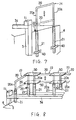
railing member 78 of a sixth embodiment of the present invention. FIG. 11 is a front view showing therailing member 78 in FIG. 10. - In this embodiment, at the time of an inspection, to insure safety of a maintenance worker as much as possible, a height of the
railing member 78 is composed to be adjustable in height before the maintenance worker steps on thecage 4. - That is, the
railing member 78 is composed of a pair offirst railing members 70 disposed on thecage 4 along the top side edges thereof so as to be adjustable in height, and asecond railing member 75 disposed on thecage 4 along the top back side of thereof so as to be adjustable in height. Thefirst railing members 70 and thesecond railing member 75 can be raised for inspection before the maintenance worker steps on thecage 4 from an elevator depot. - Each of the
first railing members 70 is composed of arailing 71 formed in the shape of an inverted U and extending from the front side of thecage 4 to the back side. Therailing 71 has twolegs 71a mounted onstands 73 on thecage 4 viahinges 72 capable of turning toward the center of thecage 4. Thus, as shown in FIG. 10, thefirst railing members 70 are installed on thecage 4 so as to stand upright and to fold toward the center of thecage 4 as indicated by double dotted chain lines. Thefirst railing members 70 are folded and lain on top of thecage frame 3a. - The
second railing member 75 is composed of achain 76 connected at opposite ends thereof to the back side ends of therailings 71. Thechain 76 is disposed between therailings 71 so as to achieve a desired height when therailings 71 stand upright. That is, thechain 76 becomes tight and loose according to up and down movement of therailings 71, thereby changing its height. - Further, ratchets 77 are attached to respective front sides of the
hinges 72 supporting thelegs 71a. Theratchets 77 lock a turning part and a fixed part of the hinges together, thereby maintaining the upright state of therailings 71. Furthermore, knobs 77a are respectively provided at theratchets 77 in order to release the lock state of theratchets 77. Thus, therailing 71 and thechain 76 can be adjusted to a height suitable for an inspection at the elevator depot without stepping on thecage 4. - According to the sixth embodiment, in case of inspection, the maintenance worker grabs one of the
legs 71a and stands therailing 71 upright by leaning out of the elevator depot before stepping on thecage 4, and then locks thehinge 72 with theratchet 77. Theother railing 71 is lifted up and locked in the same way, as a result, both sides of therailings 71 are locked and kept in upright state as shown in FIG. 10 and FIG. 11. After the inspection, the maintenance worker first steps out to the elevator depot, then releases the lock state of theratchets 77 by operating theknobs 77a and folds therailings 71 toward the center of thecage 4. Thus, the height of therailings 71 and thechain 76 can be set to a position ensuring the safety of the maintenance worker before stepping on thecage 4. - Accordingly, the maintenance worker can step on the
cage 4 after ensuring the safety, and inspect the elevator in safety. - Further, since the
railings 71 are mounted on thestands 73, in case of standing therailings 71 upright, the overall height of therailing member 78 suitable for the safety of the maintenance worker becomes the height Y equal to the sum of the height Y1 of thestands 73 and the height Y2 of therailings 71 as shown in FIG. 11. On the other hand, in case of folding therailings 71, since only therailings 71 are folded, therailing member 78 can be housed in a small space. Furthermore, in case that the height of therailing member 78 is required to change due to a change of the type of the elevator, thesame railings 71 can be used though the height of thestands 73 might be changed. - FIG. 12(a) is a perspective view of a railing member of a seventh embodiment of the present invention. FIG. 12(b) is a perspective view of a principal part of the railing member in FIG. 12(a).
- This embodiment modifies the sixth embodiment, substituting a
folding railing member 83 for thechain 76 as thesecond railing member 75. - The
railing member 83 is composed of arailing 84 formed in the shape of an inverted U. Theopposite end portions 84b of therailing 84 are formed in a crank, and pivotably supported on thecage 4 by means of a shaft bearing (not shown), thereby enabling therailing 84 to be lifted up to stand upright and to be folded toward the center of thecage 4 as shown in FIG. 12(a). - One of the
legs 71a adjacent to therailing 84 is formed in the same way as theend portion 84b. That is, one end portion 71b of thelegs 71a is pivotably supported on thecage 4 as shown in FIG. 12(b) by means of a shaft bearing (not shown). The bothend portions 84b and 71b are connected by agear member 86 composed of two bevel gears 85. Thus, if therailings 71 are folded from their standing upright state, therailing 84 is folded together therewith. On the other hand, if therailings 71 are raised up to the standing upright state, therailing 84 also stands. Only onerailing 71 need be manipulated to achieve such operation. - FIG. 13(a) is a top view of a railing member of an eighth embodiment of the present invention. FIG. 13(b) is a front view of the railing member in FIG. 13(a).
- This embodiment modifies the sixth embodiment, substituting a
link railing member 91 for thechain 76 as thesecond railing member 75. - The
railing member 91 is composed of a pair ofrailings 90 pivotably connected at one of the ends thereof to respective back side ends of therailings 71, with the other ends thereof connected together. Thus, as shown in FIG 13(b), with folding of therailings 71, therailings 90 are moved downward and folded, turning at the connectingpoint 91a. - Further, a
lock device 92 is added to therailing member 91 in order to keep a desired railing position and to disperse and reduce a load to be added to therailings 90. - The
lock device 92 is composed of anut 93 welded on back side of one of therailings 90, and abolt 94 to be screwed in thenut 93 through a hole (not shown) provided on theother railing 90 in correspondence with the location of thenut 93. Therailings 90 are locked in a straight line by means of thenut 93 and thebolt 94. - FIG. 14 is a front view of a railing member of a ninth embodiment of the present invention.
- This embodiment modifies the sixth embodiment, substituting a
link railing member 100 for thechain 76 as thesecond railing member 75. - The
railing member 100 is composed of a pair offirst railings railings 71, and aparallel railing 102 pivotably connected at opposite ends thereof to respective opposite ends of thefirst railings railings 71, therailing member 100 is moved downward and folded pivoting on their fulcrums. - According to the ninth embodiment, the entire folded height H of the
railing member 100 can be lowered. - FIG. 15(a) is a top view of a railing member of a tenth embodiment of the present invention. FIG. 15(b) is a front view of the railing member in FIG. 15(a).
- This embodiment modifies the sixth embodiment, substituting a
slide railing member 108 for thechain 76 as thesecond railing member 75. - The
railing member 108 is composed of arailing 106 having a pair of slit rails 105 extending between therailings 71, and a pair ofcam rollers 107 attached to respective back sides of therailings 71 and guided by therails 105. Thus, as shown in FIG 15(b), with folding of therailings 71, therailing member 108 is moved downward and folded, being guided by thecam rollers 107 and the slit rails 105. - The slit rails 105 can be substituted for a guide rail attached to a side of the
railing 106 without a slit. - FIG. 16 is a front view of a railing member of an eleventh embodiment of the present invention.
- This embodiment modifies the sixth embodiment, substituting an
elastic railing member 112 for thechain 76 as thesecond railing member 75. - The
railing member 112 is composed of a pair ofcylinders 111 each pivotably connected at one end thereof to respective back sides of therailings 71, and anelastic member 110 connected at opposite ends thereof to inside of thecylinders 111. Thus, as shown in FIG 16, with folding of therailings 71, therailing member 112 is moved downward, and theelastic member 110 is contracted. - FIG. 17 is a front view of a railing member of a twelfth embodiment of the present invention.
- This embodiment modifies the sixth embodiment in FIG. 10, adding an
operation prohibiting device 120, which prohibits a normal operation of the elevator until therailings 71 return to a position lower than the highest object on thecage 4, to the sixth embodiment. - The
operation prohibiting device 120 is composed of twolimit switches 121 mounted on thecage 4 viastands 123 for detecting whether therailings 71 return to a proper position, and acontroller 122. The limit switches 121 output confirmation signals to thecontroller 122 at the time therailings 71 return to a proper position for a normal operation of the elevator. Thecontroller 122 outputs a permit signal to the hoistingmachine 10 only upon receiving both confirmation signals from eachlimit switch 121 in order to allow a normal operation of the elevator. That is, the elevator can not be operated until therailings 71 return to a position lower than the highest object on thecage 4. - FIG. 18 is a front view of a railing member of a thirteenth embodiment of the present invention.
- This embodiment modifies the twelfth embodiment of FIG. 17, by mounting the limit switches 121 on the
railings 71. That is, the projections 121a of thelimit switches 121 are mounted on respective of therailings 71 such that the projections 121a contact stands 124 at the time therailings 71 fold down. - According to the thirteenth embodiment, similarly the elevator can not be operated until the
railings 71 return to a position lower than the highest object on thecage 4. - FIG. 19 is a front view of a railing member of a fourteenth embodiment of the present invention.
- This embodiment modifies the twelfth embodiment in FIG. 17, substituting a
switch device 125 for the limit switches 121. - The
switch device 125 is composed of a turningswitch 125a installed on an upper side of one of therailings 71, and aplate 126 attached on an upper side of theother railing 71 for switching on and off the turningswitch 125a by contacting the turningswitch 125a. Thus, only when bothrailings 71 are folded properly, will the turningswitch 125a contact theplate 126, and only then will theswitch device 125 output the confirmation signal to thecontroller 122. - According to the fourteenth embodiment, it is possible to detect whether both
railings 71 are folded properly by means of only oneswitch 125a. - Various modifications and variations are possible in light of the above teachings. Therefore, it is to be understood that within the scope of the appended claims, the present invention may be practiced otherwise than as specifically described herein.
Claims (13)
- An elevator comprising:a cage configured to ascend and descend in an elevator shaft; andat least one railing member disposed on said cage along a top edge of the cage and configured to be adjustable in height.
- The elevator as recited in claim 1, wherein:said railing member is configured to expand and contract vertically.
- The elevator as recited in claim 1, wherein said at least one railing member comprises:a railing; anda folding mechanism configured to fold and unfold the railing.
- The elevator as recited in claim 1, wherein said at least one railing member comprises:a plurality of railings disposed on said cage along the top edge thereof and configured to be adjustable in height;a connecting member configured to integrate adjacent of said railings.
- The elevator as recited in claim 1, wherein said at least one railing member comprises:a pair of first railing members each including a folding railing and disposed on said cage along the opposite top side edges thereof, anda second railing member disposed on said cage along the top back side edge thereof,said first railing members and said second railing member configured to be set at a desired position before a maintenance worker stands on said cage.
- The elevator as recited in claim 5, further comprising:a lock member configured to lock one of said first railing members at a desired position,said first railing members being connected with said second railing member so as to be set at said desired position in unison.
- The elevator as recited in claim 6, wherein:said second railing member comprises a chain member.
- The elevator as recited in claim 6, wherein:said second railing member comprises a folding railing.
- The elevator as recited in claim 6, wherein said second railing member comprises:a pair of levers each pivotably connected at one end thereof to respective back side ends of said first railing members, and connected together at other ends thereof, said pair of levers configured such that with the folding of said first railing member, said other ends turn downward.
- The elevator as recited in claim 6, wherein said second railing member comprises:a pair of first plates each pivotably connected at one end thereof to respective back side ends of said first railing members, anda parallel plate pivotably connected at opposite ends thereof to respective other ends of said first plates,said first plates and said parallel plate configured such that, with the folding of said first railing members, said parallel plate moves downward.
- The elevator as recited in claim 6, wherein said second railing member comprises:a pair of cams attached to respective back side ends of respective of said first railing members, anda plate extending between said first railing members and having at least one split rail configured to guide said cams, said plate and said cams configured such that with the folding of said first railing member, said plate moves downward.
- The elevator as recited in claim 6, wherein said second railing member comprises:an elastic member having opposite ends connected to respective back side ends of said first railing members, said elastic member configured to expand and contract such that with the folding of said first railing members, said elastic member moves downward.
- The elevator as recited in claim 1, further comprising:means for prohibiting a normal operation of said cage as long as said railing is not positioned lower than a highest protruded object on said cage.
Applications Claiming Priority (4)
| Application Number | Priority Date | Filing Date | Title |
|---|---|---|---|
| JP24987398 | 1998-09-03 | ||
| JP24987398 | 1998-09-03 | ||
| JP28784398 | 1998-10-09 | ||
| JP28784398A JP4245209B2 (en) | 1998-09-03 | 1998-10-09 | Elevator |
Publications (3)
| Publication Number | Publication Date |
|---|---|
| EP0985628A2 true EP0985628A2 (en) | 2000-03-15 |
| EP0985628A3 EP0985628A3 (en) | 2003-10-15 |
| EP0985628B1 EP0985628B1 (en) | 2008-04-16 |
Family
ID=26539533
Family Applications (1)
| Application Number | Title | Priority Date | Filing Date |
|---|---|---|---|
| EP99116859A Expired - Lifetime EP0985628B1 (en) | 1998-09-03 | 1999-09-03 | Elevator with adjustable top edge railing members |
Country Status (8)
| Country | Link |
|---|---|
| US (1) | US6543584B1 (en) |
| EP (1) | EP0985628B1 (en) |
| JP (1) | JP4245209B2 (en) |
| KR (1) | KR100399425B1 (en) |
| CN (1) | CN1120798C (en) |
| DE (1) | DE69938524T2 (en) |
| MY (1) | MY126540A (en) |
| TW (1) | TW446680B (en) |
Cited By (15)
| Publication number | Priority date | Publication date | Assignee | Title |
|---|---|---|---|---|
| WO2002085773A1 (en) | 2001-04-17 | 2002-10-31 | Mitsubishi Denki Kabushiki Kaisha | Elevator cage and elevator |
| WO2003018459A1 (en) * | 2001-08-27 | 2003-03-06 | Otis Elevator Company | Safety apparatus for maintenance of elevator systems from top of the car |
| WO2003020629A1 (en) | 2001-08-28 | 2003-03-13 | Mitsubishi Denki Kabushiki Kaisha | Cage and elevator |
| WO2003095350A1 (en) * | 2002-05-09 | 2003-11-20 | Otis Elevator Company | Safety fence at upper part of cab |
| WO2004000713A1 (en) * | 2002-06-20 | 2003-12-31 | Otis Elevator Company | Safety top balustrade for a car of a machine room-less elevator |
| FR2866665A1 (en) * | 2004-02-24 | 2005-08-26 | Juan Perea | Guardrail type safety device, has control unit controlling jack type linear actuator to move and maintain retaining unit in deployed position and to restore unit in retracted position, and net stretching across device in deployed position |
| WO2006087598A1 (en) * | 2005-02-18 | 2006-08-24 | Otis Elevator Company | Roof railing for an elevator car adapted to be collapsed with a handle actuating all sides at the same time |
| FR2891820A1 (en) * | 2005-10-07 | 2007-04-13 | Thyssenkrupp Elevator Mfg F | Lift cabin has deployable guard rail and supple side panels to protect technicians working on cabin roof |
| NL1030867C2 (en) * | 2006-01-06 | 2007-07-09 | Melker B V De | Safety construction is for lift and comprises at least two uprights, at least one horizontal piece connected with uprights, devices for fixture of construction to lift cage, at least one bolting component for securing the construction |
| WO2008004022A1 (en) * | 2006-06-30 | 2008-01-10 | Otis Elevator Company | Elevator having a shallow pit and/or a low overhead |
| US7322445B2 (en) | 2003-03-31 | 2008-01-29 | Inventio Ag | Stop bar for creating a temporary safety space within an elevator hoistway |
| EP2295363A1 (en) * | 2002-05-01 | 2011-03-16 | Mitsubishi Denki Kabushiki Kaisha | Handrail on top of elevator cage |
| US8136637B2 (en) | 2006-06-30 | 2012-03-20 | Otis Elevator Company | Safety device for securing minimum spaces at the top or bottom of an elevator shaft being inspected, and elevator having such safety devices |
| WO2018178285A1 (en) | 2017-03-30 | 2018-10-04 | Inventio Ag | Elevator |
| US11174124B2 (en) | 2016-11-15 | 2021-11-16 | Inventio Ag | Elevator car |
Families Citing this family (48)
| Publication number | Priority date | Publication date | Assignee | Title |
|---|---|---|---|---|
| CN1289377C (en) * | 2000-12-28 | 2006-12-13 | 三菱电机株式会社 | Car upper handrail device of elevator |
| JP4684445B2 (en) * | 2001-03-23 | 2011-05-18 | 三菱電機株式会社 | Elevator car equipment |
| CN1283543C (en) * | 2002-03-07 | 2006-11-08 | 三菱电机株式会社 | Handle above cage of elevator |
| US20050230194A1 (en) * | 2002-05-09 | 2005-10-20 | Ryushu Nakamura | Safety fence at upper part of cab |
| US6830127B2 (en) * | 2002-08-29 | 2004-12-14 | Robert Aaron Johnson | Pipeline construction safety platform |
| US20040104382A1 (en) * | 2002-12-02 | 2004-06-03 | Collins Douglas R. | Safety railing system for roof access hatch |
| JP2007516138A (en) * | 2003-09-15 | 2007-06-21 | オーチス エレベータ カンパニー | Elevator inspection safety device |
| US20050224299A1 (en) * | 2004-04-13 | 2005-10-13 | Soemardjan San A | Elevator recessed car top for refuge area |
| JP4627430B2 (en) * | 2004-10-21 | 2011-02-09 | 三菱電機株式会社 | Elevator car handrail device |
| CN101365641B (en) * | 2006-10-04 | 2012-04-18 | 三菱电机株式会社 | Elevator apparatus |
| WO2008070933A1 (en) * | 2006-12-15 | 2008-06-19 | C. & V. Engineering Company Pty. Ltd. | An improved fall safety barrier |
| JP2008174337A (en) * | 2007-01-17 | 2008-07-31 | Mitsubishi Electric Corp | Car top handrail device |
| JP4944628B2 (en) * | 2007-01-26 | 2012-06-06 | パナソニック ホームエレベーター株式会社 | Handrail structure of work table of elevator equipment |
| JP2008285266A (en) * | 2007-05-16 | 2008-11-27 | Toshiba Elevator Co Ltd | Safety device for on-elevator car work |
| KR100907140B1 (en) | 2007-07-04 | 2009-07-09 | 미쓰비시덴키 가부시키가이샤 | Elevator apparatus |
| JP5360645B2 (en) * | 2008-07-23 | 2013-12-04 | 日本ビソー株式会社 | Folding work gondola |
| JP4836286B2 (en) * | 2008-10-21 | 2011-12-14 | 東芝エレベータ株式会社 | Elevator equipment |
| US20110088972A1 (en) * | 2009-10-20 | 2011-04-21 | Kirk Bradley Gregus | Elevator work deck |
| CN103562115B (en) * | 2011-06-22 | 2016-07-06 | 因温特奥股份公司 | Fire lift |
| PT2766292T (en) * | 2011-10-13 | 2016-07-29 | Inventio Ag | Lift |
| JP5877909B2 (en) | 2011-12-21 | 2016-03-08 | オーチス エレベータ カンパニーOtis Elevator Company | Elevator system including a cage stop to maintain headspace |
| CN104379483A (en) * | 2012-07-20 | 2015-02-25 | 株式会社日立制作所 | Elevator device |
| CN103011033B (en) * | 2012-12-21 | 2015-08-12 | 中联重科股份有限公司 | High-altitude platform system and comprise the construction machinery and equipment of this high-altitude platform system |
| JP5778722B2 (en) * | 2013-07-23 | 2015-09-16 | オーチス エレベータ カンパニーOtis Elevator Company | Elevator with shallow pits and / or low overhead |
| KR101432643B1 (en) | 2013-12-31 | 2014-08-22 | 주식회사 삼덕티엘에스 | A safty container gondola of height adjusting type for distribution |
| JP6145078B2 (en) * | 2014-04-23 | 2017-06-07 | 株式会社シィップ | Lifting platform device |
| WO2016110934A1 (en) * | 2015-01-05 | 2016-07-14 | 三菱電機株式会社 | Elevator apparatus |
| MY184216A (en) * | 2015-01-20 | 2021-03-26 | Inventio Ag | Elevator |
| DE112015006235T5 (en) * | 2015-02-26 | 2017-12-28 | Mitsubishi Electric Corporation | LIFT DEVICE |
| DE102015211488A1 (en) | 2015-06-22 | 2016-12-22 | Thyssenkrupp Ag | Safety device of an elevator installation |
| DE112015006696T5 (en) * | 2015-07-15 | 2018-03-29 | Mitsubishi Electric Corporation | winder |
| JP6366847B2 (en) * | 2015-07-23 | 2018-08-01 | 三菱電機株式会社 | Elevator car handrail device |
| AU2016333499B2 (en) * | 2015-09-30 | 2019-06-20 | Inventio Ag | Lift system |
| US10836605B2 (en) * | 2015-12-18 | 2020-11-17 | Inventio Ag | Elevator car with a foldable balustrade and control device for an elevator installation having such an elevator car |
| WO2018011976A1 (en) * | 2016-07-15 | 2018-01-18 | 三菱電機株式会社 | Elevator device |
| CN109843773B (en) * | 2016-10-18 | 2020-08-07 | 三菱电机株式会社 | Handrail device on car of elevator |
| JP6584691B2 (en) * | 2016-10-27 | 2019-10-02 | 三菱電機株式会社 | Elevator car handrail device |
| DE102016121742A1 (en) * | 2016-11-14 | 2018-05-17 | Thyssenkrupp Ag | Car for an elevator system |
| CN108557602A (en) * | 2018-06-27 | 2018-09-21 | 通力电梯有限公司 | Safety device for elevator and the elevator including the safety device |
| KR20200025780A (en) | 2018-08-31 | 2020-03-10 | 이금기 | Safety railing for elevators |
| CN111362085B (en) * | 2018-12-26 | 2022-12-20 | 奥的斯电梯公司 | Railing subassembly, car and elevator |
| JP7135902B2 (en) * | 2019-02-01 | 2022-09-13 | 三菱電機株式会社 | Elevator car ceiling baseboard device |
| EP4077186A1 (en) * | 2019-12-20 | 2022-10-26 | Inventio Ag | Elevator car pivotable balustrade and maintenance method for an elevator |
| CN111302191A (en) * | 2020-03-31 | 2020-06-19 | 瑞普兰德电梯有限公司 | Safety protection rail in elevator car |
| KR102205714B1 (en) * | 2020-08-10 | 2021-01-21 | 아세아시멘트(주) | Hand rail for silo device with folding function and silo device containing the same |
| CN114074884A (en) * | 2020-08-13 | 2022-02-22 | 奥的斯电梯公司 | Top expansion part and operation method thereof, elevator car assembly and elevator system |
| EP4005961A1 (en) | 2020-11-30 | 2022-06-01 | Inventio AG | Elevator with a balustrade |
| CN113682921A (en) * | 2021-08-24 | 2021-11-23 | 崔晓江 | Simple hoistway platform |
Citations (2)
| Publication number | Priority date | Publication date | Assignee | Title |
|---|---|---|---|---|
| GB2158038A (en) | 1984-04-27 | 1985-11-06 | Afd Engineering | Lift car top barrier |
| JPH01281281A (en) | 1988-05-06 | 1989-11-13 | Mitsubishi Electric Corp | Cage upper safety fence |
Family Cites Families (8)
| Publication number | Priority date | Publication date | Assignee | Title |
|---|---|---|---|---|
| US3878916A (en) * | 1973-02-07 | 1975-04-22 | Jr Gerome R White | Rack and pinion drive counterbalanced hoist systems |
| JPH0649577Y2 (en) * | 1987-11-27 | 1994-12-14 | 株式会社日立ビルシステムサービス | Elevator maintenance operation equipment |
| JPH0625471B2 (en) * | 1989-09-28 | 1994-04-06 | 株式会社竹中工務店 | Folding scaffolding |
| JPH04292386A (en) * | 1991-03-20 | 1992-10-16 | Toshiba Corp | Safety fence for hydraulic elevator cage |
| JPH08133617A (en) * | 1994-11-02 | 1996-05-28 | Mitsubishi Denki Bill Techno Service Kk | Maintenance device on elevator cage top |
| JP2001058774A (en) * | 1999-08-18 | 2001-03-06 | Hitachi Building Systems Co Ltd | Elevator |
| JP2002003113A (en) * | 2000-06-15 | 2002-01-09 | Hitachi Building Systems Co Ltd | Car top maintenance and operation device of elevator |
| JP2002020062A (en) * | 2000-07-07 | 2002-01-23 | Mitsubishi Electric Corp | Elevator cage device |
-
1998
- 1998-10-09 JP JP28784398A patent/JP4245209B2/en not_active Expired - Fee Related
-
1999
- 1999-08-27 TW TW088114754A patent/TW446680B/en not_active IP Right Cessation
- 1999-08-30 MY MYPI99003734A patent/MY126540A/en unknown
- 1999-09-01 KR KR10-1999-0036869A patent/KR100399425B1/en not_active IP Right Cessation
- 1999-09-02 CN CN99118960A patent/CN1120798C/en not_active Expired - Fee Related
- 1999-09-03 DE DE69938524T patent/DE69938524T2/en not_active Expired - Lifetime
- 1999-09-03 EP EP99116859A patent/EP0985628B1/en not_active Expired - Lifetime
- 1999-09-03 US US09/389,473 patent/US6543584B1/en not_active Expired - Fee Related
Patent Citations (2)
| Publication number | Priority date | Publication date | Assignee | Title |
|---|---|---|---|---|
| GB2158038A (en) | 1984-04-27 | 1985-11-06 | Afd Engineering | Lift car top barrier |
| JPH01281281A (en) | 1988-05-06 | 1989-11-13 | Mitsubishi Electric Corp | Cage upper safety fence |
Non-Patent Citations (1)
| Title |
|---|
| PATENT ABSTRACTS OF JAPAN vol. 014, no. 056 (M - 0929) 31 January 1990 (1990-01-31) |
Cited By (29)
| Publication number | Priority date | Publication date | Assignee | Title |
|---|---|---|---|---|
| EP1386876A4 (en) * | 2001-04-17 | 2004-06-23 | Mitsubishi Electric Corp | Elevator cage and elevator |
| WO2002085773A1 (en) | 2001-04-17 | 2002-10-31 | Mitsubishi Denki Kabushiki Kaisha | Elevator cage and elevator |
| EP1386876A1 (en) * | 2001-04-17 | 2004-02-04 | Mitsubishi Denki Kabushiki Kaisha | Elevator cage and elevator |
| WO2003018459A1 (en) * | 2001-08-27 | 2003-03-06 | Otis Elevator Company | Safety apparatus for maintenance of elevator systems from top of the car |
| WO2003020629A1 (en) | 2001-08-28 | 2003-03-13 | Mitsubishi Denki Kabushiki Kaisha | Cage and elevator |
| EP1422185A4 (en) * | 2001-08-28 | 2010-06-23 | Mitsubishi Electric Corp | Cage and elevator |
| EP1422185A1 (en) * | 2001-08-28 | 2004-05-26 | Mitsubishi Denki Kabushiki Kaisha | Cage and elevator |
| EP2295363A1 (en) * | 2002-05-01 | 2011-03-16 | Mitsubishi Denki Kabushiki Kaisha | Handrail on top of elevator cage |
| WO2003095350A1 (en) * | 2002-05-09 | 2003-11-20 | Otis Elevator Company | Safety fence at upper part of cab |
| JP2005532966A (en) * | 2002-06-20 | 2005-11-04 | オーチス エレベータ カンパニー | Upper safety fence for machine room-less elevator car |
| US7140473B2 (en) | 2002-06-20 | 2006-11-28 | Otis Elevator Company | Safety top balustrade for a car of a machine room-less elevator |
| CN1309649C (en) * | 2002-06-20 | 2007-04-11 | 奥蒂斯电梯公司 | Safety top balustrade for car of machine room-less elevator |
| WO2004000713A1 (en) * | 2002-06-20 | 2003-12-31 | Otis Elevator Company | Safety top balustrade for a car of a machine room-less elevator |
| US7886879B2 (en) | 2003-03-31 | 2011-02-15 | Inventio Ag | Method for creating temporary safety space within an elevator hoistway |
| US7322445B2 (en) | 2003-03-31 | 2008-01-29 | Inventio Ag | Stop bar for creating a temporary safety space within an elevator hoistway |
| FR2866665A1 (en) * | 2004-02-24 | 2005-08-26 | Juan Perea | Guardrail type safety device, has control unit controlling jack type linear actuator to move and maintain retaining unit in deployed position and to restore unit in retracted position, and net stretching across device in deployed position |
| US7510056B2 (en) | 2005-02-18 | 2009-03-31 | Otis Elevator Company | Roof railing for an elevator car adapted to be collapsed with a handle actuating all sides at the same time |
| WO2006087598A1 (en) * | 2005-02-18 | 2006-08-24 | Otis Elevator Company | Roof railing for an elevator car adapted to be collapsed with a handle actuating all sides at the same time |
| FR2891820A1 (en) * | 2005-10-07 | 2007-04-13 | Thyssenkrupp Elevator Mfg F | Lift cabin has deployable guard rail and supple side panels to protect technicians working on cabin roof |
| NL1030867C2 (en) * | 2006-01-06 | 2007-07-09 | Melker B V De | Safety construction is for lift and comprises at least two uprights, at least one horizontal piece connected with uprights, devices for fixture of construction to lift cage, at least one bolting component for securing the construction |
| EP2033927A1 (en) * | 2006-06-30 | 2009-03-11 | Otis Elevator Company | Elevator having a shallow pit and/or a low overhead |
| WO2008004022A1 (en) * | 2006-06-30 | 2008-01-10 | Otis Elevator Company | Elevator having a shallow pit and/or a low overhead |
| US8136637B2 (en) | 2006-06-30 | 2012-03-20 | Otis Elevator Company | Safety device for securing minimum spaces at the top or bottom of an elevator shaft being inspected, and elevator having such safety devices |
| US8162108B2 (en) | 2006-06-30 | 2012-04-24 | Otis Elevator Company | Elevator having a limit switch for controlling power to the drive system as an elevator car approaches a shallow pit or a low overhead |
| US8365870B2 (en) | 2006-06-30 | 2013-02-05 | Otis Elevator Company | Foldable handrail and safety switch arrangement on top of an elevator car |
| CN101472830B (en) * | 2006-06-30 | 2013-07-17 | 奥蒂斯电梯公司 | Elevator with shallow well delve and/or low roof cover |
| US11174124B2 (en) | 2016-11-15 | 2021-11-16 | Inventio Ag | Elevator car |
| EP3541734B1 (en) | 2016-11-15 | 2023-03-22 | Inventio Ag | Elevator car |
| WO2018178285A1 (en) | 2017-03-30 | 2018-10-04 | Inventio Ag | Elevator |
Also Published As
| Publication number | Publication date |
|---|---|
| KR20000022841A (en) | 2000-04-25 |
| MY126540A (en) | 2006-10-31 |
| US6543584B1 (en) | 2003-04-08 |
| CN1246437A (en) | 2000-03-08 |
| DE69938524D1 (en) | 2008-05-29 |
| DE69938524T2 (en) | 2009-06-10 |
| KR100399425B1 (en) | 2003-09-29 |
| JP4245209B2 (en) | 2009-03-25 |
| TW446680B (en) | 2001-07-21 |
| EP0985628B1 (en) | 2008-04-16 |
| JP2000143125A (en) | 2000-05-23 |
| CN1120798C (en) | 2003-09-10 |
| EP0985628A3 (en) | 2003-10-15 |
Similar Documents
| Publication | Publication Date | Title |
|---|---|---|
| US6543584B1 (en) | Elevator with adjustable top edge railing members | |
| CN110194405B (en) | Elevator car and elevator system comprising an elevator car | |
| CN201665485U (en) | Internal-climbing device of tower crane and internal-climbing component of tower crane | |
| US11192754B2 (en) | Elevator arrangement and elevator | |
| CA1146096A (en) | Modular elevator car | |
| JP2007063021A (en) | Lift cage with maintenance platform and maintenance method for lift facility | |
| CN103167998A (en) | Elevator control panel | |
| KR20070037995A (en) | Method of mounting a support means of a lift cage to a lift cage and to a lift shaft | |
| KR970026875A (en) | Elevator lift frame locking device for building during loading and unloading of horizontal movable cap | |
| CN101066733A (en) | Foldable overhaul platform | |
| JP5217073B2 (en) | Car and elevator equipment | |
| EP1509473B1 (en) | Safety fence at upper part of cab | |
| CN111634786A (en) | Working platform for elevator car | |
| US11198594B2 (en) | Elevator car apron | |
| CN1393389A (en) | Scaffold and elevator for mounting shaft equipment and method for mounting shaft equipment | |
| KR20200025780A (en) | Safety railing for elevators | |
| CN102232050A (en) | Elevator system including control electronics supported on an elevator machine support | |
| US20050230194A1 (en) | Safety fence at upper part of cab | |
| EP1481936B1 (en) | Elevator car comprising a car top handrail | |
| EP0687644A2 (en) | Suspension arrangement for a hydraulic elevator | |
| EP3599210B1 (en) | Elevator car apron | |
| US10689232B2 (en) | Floor covering of a passenger conveyor | |
| CN110182670A (en) | A kind of bottom hanging type external application hoistway elevator device | |
| KR101820954B1 (en) | Foldable work stage for suspension scaffold | |
| EP1329411B1 (en) | Elevator device |
Legal Events
| Date | Code | Title | Description |
|---|---|---|---|
| PUAI | Public reference made under article 153(3) epc to a published international application that has entered the european phase |
Free format text: ORIGINAL CODE: 0009012 |
|
| 17P | Request for examination filed |
Effective date: 19990903 |
|
| AK | Designated contracting states |
Kind code of ref document: A2 Designated state(s): AT BE CH CY DE DK ES FI FR GB GR IE IT LI LU MC NL PT SE |
|
| AX | Request for extension of the european patent |
Free format text: AL;LT;LV;MK;RO;SI |
|
| PUAL | Search report despatched |
Free format text: ORIGINAL CODE: 0009013 |
|
| AK | Designated contracting states |
Kind code of ref document: A3 Designated state(s): AT BE CH CY DE DK ES FI FR GB GR IE IT LI LU MC NL PT SE |
|
| AX | Request for extension of the european patent |
Extension state: AL LT LV MK RO SI |
|
| RIC1 | Information provided on ipc code assigned before grant |
Ipc: 7B 66B 11/02 B Ipc: 7B 66B 5/00 B Ipc: 7B 66B 13/24 A |
|
| TPAC | Observations filed by third parties |
Free format text: ORIGINAL CODE: EPIDOSNTIPA |
|
| AKX | Designation fees paid |
Designated state(s): CH DE FI LI |
|
| GRAP | Despatch of communication of intention to grant a patent |
Free format text: ORIGINAL CODE: EPIDOSNIGR1 |
|
| 17Q | First examination report despatched |
Effective date: 20070615 |
|
| GRAS | Grant fee paid |
Free format text: ORIGINAL CODE: EPIDOSNIGR3 |
|
| GRAA | (expected) grant |
Free format text: ORIGINAL CODE: 0009210 |
|
| AK | Designated contracting states |
Kind code of ref document: B1 Designated state(s): CH DE FI LI |
|
| REG | Reference to a national code |
Ref country code: CH Ref legal event code: EP |
|
| REF | Corresponds to: |
Ref document number: 69938524 Country of ref document: DE Date of ref document: 20080529 Kind code of ref document: P |
|
| REG | Reference to a national code |
Ref country code: CH Ref legal event code: NV |
|
| PLBE | No opposition filed within time limit |
Free format text: ORIGINAL CODE: 0009261 |
|
| STAA | Information on the status of an ep patent application or granted ep patent |
Free format text: STATUS: NO OPPOSITION FILED WITHIN TIME LIMIT |
|
| 26N | No opposition filed |
Effective date: 20090119 |
|
| PGFP | Annual fee paid to national office [announced via postgrant information from national office to epo] |
Ref country code: CH Payment date: 20110913 Year of fee payment: 13 |
|
| PGFP | Annual fee paid to national office [announced via postgrant information from national office to epo] |
Ref country code: DE Payment date: 20110831 Year of fee payment: 13 Ref country code: FI Payment date: 20110912 Year of fee payment: 13 |
|
| PG25 | Lapsed in a contracting state [announced via postgrant information from national office to epo] |
Ref country code: FI Free format text: LAPSE BECAUSE OF NON-PAYMENT OF DUE FEES Effective date: 20120903 |
|
| REG | Reference to a national code |
Ref country code: CH Ref legal event code: PL |
|
| PG25 | Lapsed in a contracting state [announced via postgrant information from national office to epo] |
Ref country code: LI Free format text: LAPSE BECAUSE OF NON-PAYMENT OF DUE FEES Effective date: 20120930 Ref country code: CH Free format text: LAPSE BECAUSE OF NON-PAYMENT OF DUE FEES Effective date: 20120930 Ref country code: DE Free format text: LAPSE BECAUSE OF NON-PAYMENT OF DUE FEES Effective date: 20130403 |
|
| REG | Reference to a national code |
Ref country code: DE Ref legal event code: R119 Ref document number: 69938524 Country of ref document: DE Effective date: 20130403 |