EP0946985B1 - Agencement de cellules de memoire et son procede de fabrication - Google Patents
Agencement de cellules de memoire et son procede de fabrication Download PDFInfo
- Publication number
- EP0946985B1 EP0946985B1 EP97951797A EP97951797A EP0946985B1 EP 0946985 B1 EP0946985 B1 EP 0946985B1 EP 97951797 A EP97951797 A EP 97951797A EP 97951797 A EP97951797 A EP 97951797A EP 0946985 B1 EP0946985 B1 EP 0946985B1
- Authority
- EP
- European Patent Office
- Prior art keywords
- memory cell
- layer
- gate electrodes
- trenches
- semiconductor substrate
- Prior art date
- Legal status (The legal status is an assumption and is not a legal conclusion. Google has not performed a legal analysis and makes no representation as to the accuracy of the status listed.)
- Expired - Lifetime
Links
- 230000015654 memory Effects 0.000 title claims description 108
- 238000000034 method Methods 0.000 title claims description 23
- 238000004519 manufacturing process Methods 0.000 title description 5
- 239000000758 substrate Substances 0.000 claims description 33
- 239000004065 semiconductor Substances 0.000 claims description 27
- 125000006850 spacer group Chemical group 0.000 claims description 19
- 239000002800 charge carrier Substances 0.000 claims description 16
- VYPSYNLAJGMNEJ-UHFFFAOYSA-N Silicium dioxide Chemical compound O=[Si]=O VYPSYNLAJGMNEJ-UHFFFAOYSA-N 0.000 claims description 15
- 239000000463 material Substances 0.000 claims description 7
- 229910052581 Si3N4 Inorganic materials 0.000 claims description 6
- 238000002955 isolation Methods 0.000 claims description 6
- 238000009413 insulation Methods 0.000 claims description 5
- 229910052804 chromium Inorganic materials 0.000 claims description 4
- 229910052759 nickel Inorganic materials 0.000 claims description 4
- 229910052763 palladium Inorganic materials 0.000 claims description 4
- 229910052697 platinum Inorganic materials 0.000 claims description 4
- 229910052721 tungsten Inorganic materials 0.000 claims description 4
- 239000012535 impurity Substances 0.000 claims 6
- GWEVSGVZZGPLCZ-UHFFFAOYSA-N Titan oxide Chemical compound O=[Ti]=O GWEVSGVZZGPLCZ-UHFFFAOYSA-N 0.000 claims 4
- PNEYBMLMFCGWSK-UHFFFAOYSA-N aluminium oxide Inorganic materials [O-2].[O-2].[O-2].[Al+3].[Al+3] PNEYBMLMFCGWSK-UHFFFAOYSA-N 0.000 claims 4
- 229910052681 coesite Inorganic materials 0.000 claims 4
- 229910052593 corundum Inorganic materials 0.000 claims 4
- 229910052906 cristobalite Inorganic materials 0.000 claims 4
- 239000000377 silicon dioxide Substances 0.000 claims 4
- 229910052682 stishovite Inorganic materials 0.000 claims 4
- 239000000126 substance Substances 0.000 claims 4
- 229910052905 tridymite Inorganic materials 0.000 claims 4
- 229910001845 yogo sapphire Inorganic materials 0.000 claims 4
- 229910052741 iridium Inorganic materials 0.000 claims 2
- PBCFLUZVCVVTBY-UHFFFAOYSA-N tantalum pentoxide Inorganic materials O=[Ta](=O)O[Ta](=O)=O PBCFLUZVCVVTBY-UHFFFAOYSA-N 0.000 claims 2
- 238000002513 implantation Methods 0.000 description 34
- 229910004298 SiO 2 Inorganic materials 0.000 description 25
- 238000005530 etching Methods 0.000 description 21
- 230000015572 biosynthetic process Effects 0.000 description 14
- 238000000151 deposition Methods 0.000 description 13
- 239000002019 doping agent Substances 0.000 description 12
- 238000009792 diffusion process Methods 0.000 description 9
- 229910052751 metal Inorganic materials 0.000 description 8
- 239000002184 metal Substances 0.000 description 8
- 229910021420 polycrystalline silicon Inorganic materials 0.000 description 8
- 229920005591 polysilicon Polymers 0.000 description 8
- 230000008021 deposition Effects 0.000 description 7
- 229910052814 silicon oxide Inorganic materials 0.000 description 7
- 238000003860 storage Methods 0.000 description 7
- KRHYYFGTRYWZRS-UHFFFAOYSA-N Fluorane Chemical compound F KRHYYFGTRYWZRS-UHFFFAOYSA-N 0.000 description 6
- 150000002500 ions Chemical class 0.000 description 6
- 229920002120 photoresistant polymer Polymers 0.000 description 5
- 229910018072 Al 2 O 3 Inorganic materials 0.000 description 4
- ZOXJGFHDIHLPTG-UHFFFAOYSA-N Boron Chemical compound [B] ZOXJGFHDIHLPTG-UHFFFAOYSA-N 0.000 description 4
- OAICVXFJPJFONN-UHFFFAOYSA-N Phosphorus Chemical compound [P] OAICVXFJPJFONN-UHFFFAOYSA-N 0.000 description 4
- BOTDANWDWHJENH-UHFFFAOYSA-N Tetraethyl orthosilicate Chemical compound CCO[Si](OCC)(OCC)OCC BOTDANWDWHJENH-UHFFFAOYSA-N 0.000 description 4
- 229910052796 boron Inorganic materials 0.000 description 4
- 239000002784 hot electron Substances 0.000 description 4
- 238000002347 injection Methods 0.000 description 4
- 239000007924 injection Substances 0.000 description 4
- 239000005368 silicate glass Substances 0.000 description 4
- 239000004020 conductor Substances 0.000 description 3
- 238000011065 in-situ storage Methods 0.000 description 3
- 229910021421 monocrystalline silicon Inorganic materials 0.000 description 3
- 230000003071 parasitic effect Effects 0.000 description 3
- 229910052698 phosphorus Inorganic materials 0.000 description 3
- 239000011574 phosphorus Substances 0.000 description 3
- 229910021332 silicide Inorganic materials 0.000 description 3
- FVBUAEGBCNSCDD-UHFFFAOYSA-N silicide(4-) Chemical compound [Si-4] FVBUAEGBCNSCDD-UHFFFAOYSA-N 0.000 description 3
- 230000005689 Fowler Nordheim tunneling Effects 0.000 description 2
- XUIMIQQOPSSXEZ-UHFFFAOYSA-N Silicon Chemical compound [Si] XUIMIQQOPSSXEZ-UHFFFAOYSA-N 0.000 description 2
- 229910010413 TiO 2 Inorganic materials 0.000 description 2
- 229910052782 aluminium Inorganic materials 0.000 description 2
- XAGFODPZIPBFFR-UHFFFAOYSA-N aluminium Chemical compound [Al] XAGFODPZIPBFFR-UHFFFAOYSA-N 0.000 description 2
- 239000000969 carrier Substances 0.000 description 2
- 239000013078 crystal Substances 0.000 description 2
- 238000005516 engineering process Methods 0.000 description 2
- 238000001465 metallisation Methods 0.000 description 2
- 230000003647 oxidation Effects 0.000 description 2
- 238000007254 oxidation reaction Methods 0.000 description 2
- 229910052710 silicon Inorganic materials 0.000 description 2
- 239000010703 silicon Substances 0.000 description 2
- HQVNEWCFYHHQES-UHFFFAOYSA-N silicon nitride Chemical compound N12[Si]34N5[Si]62N3[Si]51N64 HQVNEWCFYHHQES-UHFFFAOYSA-N 0.000 description 2
- 239000011248 coating agent Substances 0.000 description 1
- 238000000576 coating method Methods 0.000 description 1
- 230000000295 complement effect Effects 0.000 description 1
- 238000009826 distribution Methods 0.000 description 1
- 238000001312 dry etching Methods 0.000 description 1
- 230000000694 effects Effects 0.000 description 1
- 230000010354 integration Effects 0.000 description 1
- 238000012856 packing Methods 0.000 description 1
- 238000000206 photolithography Methods 0.000 description 1
- 238000003631 wet chemical etching Methods 0.000 description 1
Images


Classifications
-
- H—ELECTRICITY
- H01—ELECTRIC ELEMENTS
- H01L—SEMICONDUCTOR DEVICES NOT COVERED BY CLASS H10
- H01L29/00—Semiconductor devices adapted for rectifying, amplifying, oscillating or switching, or capacitors or resistors with at least one potential-jump barrier or surface barrier, e.g. PN junction depletion layer or carrier concentration layer; Details of semiconductor bodies or of electrodes thereof ; Multistep manufacturing processes therefor
- H01L29/40—Electrodes ; Multistep manufacturing processes therefor
- H01L29/401—Multistep manufacturing processes
- H01L29/4011—Multistep manufacturing processes for data storage electrodes
- H01L29/40117—Multistep manufacturing processes for data storage electrodes the electrodes comprising a charge-trapping insulator
-
- H—ELECTRICITY
- H10—SEMICONDUCTOR DEVICES; ELECTRIC SOLID-STATE DEVICES NOT OTHERWISE PROVIDED FOR
- H10B—ELECTRONIC MEMORY DEVICES
- H10B41/00—Electrically erasable-and-programmable ROM [EEPROM] devices comprising floating gates
-
- H—ELECTRICITY
- H10—SEMICONDUCTOR DEVICES; ELECTRIC SOLID-STATE DEVICES NOT OTHERWISE PROVIDED FOR
- H10B—ELECTRONIC MEMORY DEVICES
- H10B43/00—EEPROM devices comprising charge-trapping gate insulators
- H10B43/30—EEPROM devices comprising charge-trapping gate insulators characterised by the memory core region
-
- H—ELECTRICITY
- H10—SEMICONDUCTOR DEVICES; ELECTRIC SOLID-STATE DEVICES NOT OTHERWISE PROVIDED FOR
- H10B—ELECTRONIC MEMORY DEVICES
- H10B69/00—Erasable-and-programmable ROM [EPROM] devices not provided for in groups H10B41/00 - H10B63/00, e.g. ultraviolet erasable-and-programmable ROM [UVEPROM] devices
Definitions
- Memory is needed for many electronic systems the dates are firmly registered. Such storage will be among other things as read-only memory, read memory or read called only memory.
- compact discs are used as read storage used. These are plastic discs with a coating made of aluminum, in which two punctiform depressions are arranged. In the arrangement of these wells the information is stored digitally. To read the the disc is stored on a compact disc mechanically rotates a reader and it becomes the point-like Depressions scanned. On a compact disc 5 Gbit information is stored.
- the reader has moving parts that are subject to mechanical wear are subject to a comparatively large volume need and which only allow slow data access.
- the reader is also sensitive to vibrations and therefore only of limited use in mobile systems.
- Read-only memories based on semiconductors allow one random access to the stored information. About that They can also be used for mobile systems because they are for reading the information does not require a mechanical drive.
- MOS transistors are usually stored in these read-only memories used. The reading process evaluates whether a current flows through the transistor or not. Corresponding the stored information is assigned. Technically the storage of the information is usually effected by that the MOS transistors through different implantations have different threshold voltages in the channel area.
- the storage density that can be achieved in read-only memories based on semiconductors depends on the space requirement per memory cell.
- the MOS transistors arranged in rows includes. In each row there are the MOS transistors connected in series. To increase the storage density are Adjacent rows each at the bottom of stripe-shaped Longitudinal trenches and between adjacent strip-shaped longitudinal trenches arranged on the surface of the substrate. Together connected source / drain regions are connected endowed area. By line-by-line control in the sense of a "NAND" architecture, the MOS transistors read out.
- a read-only memory cell arrangement is known from US Pat. No. 5,317,534.
- strip-shaped word lines are generated, their spacing through the thickness of an insulation layer - and therefore independent from a photolithography used - is determined.
- word lines are first generated, which have a thin insulation layer. Then be the gaps by filling with conductive material each provided with another word line. So that is both a NAND and a NOR arrangement possible.
- Another memory cell arrangement is known from US 5 343 423. It comprises a semiconductor substrate in which a variety of tubs that are electrically insulated from each other are. A large number of memory cells are in rows in the tubs and arranged columns that have control electrodes. A large number of control lines are connected to the respective control electrodes connected. At the tubs are controllable first Tensions applied. Controllable lines become controllable second voltages applied. The first tension and the second Voltage is applied so that a potential difference between the tub and the control electrode of a memory cell arises that is sufficient to enroll or delete Data is in the memory cell, the source / drain regions float in the memory cell. By controlling the First and second voltages make the memory cells selective brought into the write state or the delete state.
- EP 0 673 070 A2 describes an EEPROM arrangement with NAND architecture known. Planar transistors are alternating on the bottom of stripe-shaped trenches and on the substrate surface between adjacent stripe-shaped trenches arranged. This ensures a high packing density.
- U.S. Patent No. 4,047,974 discloses a non-volatile memory cell arrangement known as MOS transistors as memory cells be used. There is an isolating one between source and drain Layer arranged in the by implantation of ions Areas with increased charge carrier cross section introduced become.
- the memory cell arrangements described are programmed during manufacture. For many applications, however, memories are required in which data can be written by electrical programming.
- electrically programmable memory cell arrangements the storage of the information is usually brought about by the fact that between the gate and the channel region of the MOS transistors there is a floating gate which can be charged with an electrical charge, or a double layer of SiO 2 and Si 3 N 4 as the gate dielectric at the interface of which electrical charge carriers can be held at detention points.
- the threshold voltage of the MOS transistor depends on the charge on the floating gate or the traps. This property is used for electrical programming (see for example SM Sze, Semiconductor Devices, John Wiley, pages 486 to 490).
- the invention is based on the problem of a memory cell arrangement specify which is electrically programmable and which is suitable for storing large amounts of data. Farther a method for their production is to be specified.
- the memory cell arrangement comprises in a semiconductor substrate multiple rows of memory cells. Adjacent rows of memory cells are isolated from each other.
- the memory cell rows each have a first doped Area and a second endowed area. Between the first doped area and the second doped area a gate dielectric on a main surface of the semiconductor substrate and a plurality of gate electrodes arranged side by side arranged. The distance between adjacent gate electrodes is smaller than the dimensions of the gate electrodes parallel to the connecting line between the first doped Area and the second endowed area.
- the gate dielectric contains a material with charge carrier traps.
- Detention areas English traps, have the properties of charge carriers, specifically to capture electrons.
- the gate electrodes are wired so that load carriers corresponding to the information to be stored get into the gate dielectric below the gate electrode and detained by the detention centers. Because the load carriers are trapped in the detention centers is the information saved permanently.
- the programmed memory cell arrangement therefore represents a fixed value memory cell arrangement. Programming can be done both through Fowler-Nordheim tunnels as well as by hot electron injection. By repentance The polarities in the Fowler-Nordheim tunnel can cause charge carriers be removed from the detention so that the programming the memory cell arrangement is changed.
- the invention is based on the following considerations: When driving a line in which MOS transistors connected in series are arranged, in the sense of a "NAND" architecture the gate electrodes of the MOS transistors are wired so that all the MOS transistors except for the selected MOS transistor conduct, regardless of the individual's tension unselected transistor. This is done that a voltage is applied to the gate electrodes that is higher than the highest threshold voltage that occurs. The The gate electrode of the selected MOS transistor, however, is supplied with a voltage between the threshold voltages of the MOS transistors. It is evaluated whether a current through the series-connected MOS transistors flows or not. If a current flows, it is in the selected one MOS transistor the information corresponding to the lesser Threshold voltage saved. If there is no current, it is the information is stored according to the higher threshold voltage.
- the invention takes advantage of the knowledge that most Source / drain regions of these MOS transistors when reading only as a conductive connection between neighboring ones conductive channels. Therefore, in the invention Memory cell arrangement only at the beginning and at the end of each Memory cell row a doped region corresponding to a Source / drain area arranged between which close together arranged gate electrodes by appropriate wiring a space charge region up to the channel region of the cause selected gate electrode. This way, in the memory cell rows the space required for between two adjacent source electrodes arranged source / drain regions saved.
- the stray field between neighboring controlled Gate electrodes causes the area below the Gaps between adjacent gate electrodes conductive is made.
- the distance between adjacent ones is preferably Gate electrodes 10 to 100 nm.
- the stray field between adjacent driven gate electrodes is not sufficient to make the area below the space between the adjacent gate electrodes conductive
- a dopant concentration in the range of 10 17 cm -3 is sufficient for this.
- This dopant concentration is significantly lower than in the first doped region and the second doped region, which, like source / drain regions, have a dopant concentration in the range from 10 20 to 10 21 cm -3 .
- Counter doping only serves to modulate adjacent space charge zones, it is not comparable with conventional source / drain regions.
- Gate dielectric introduced so that two in the arrangement different threshold voltages occur. Should the memory cell arrangement be used for value added logic, so is the gate dielectric by appropriate voltage and Programming time conditions with different Amounts of charge applied depending on the stored Information more than two different threshold voltages will be realized.
- the gate dielectric is designed as a multiple layer, in which at least one layer is provided which has an increased charge carrier cross-section in comparison with at least one further layer in the multiple layer.
- the traps are located at the interface between the two layers.
- the dielectric multilayer preferably comprises an SiO 2 layer, an Si 3 N 4 layer and an SiO 2 layer (so-called ONO).
- the gate dielectric can be a multilayer made of other materials, the layer with the increased charge carrier capture cross section consisting, for example, of Si 3 N 4 , Ta 2 O 5 , Al 2 O 3 or TiO 2 and the adjacent layer of SiO 2 , Si 3 N 4 or Al 2 O 3 exist.
- the multilayer can comprise more or less than three layers.
- the gate dielectric can comprise a dielectric layer, for example made of SiO 2 , in which foreign atoms, for example W, Pt, Cr, Ni, Pd, or Ir, are embedded.
- the embedded foreign atoms can be introduced by implantation, by addition during oxidation or by diffusion. In this case, the embedded foreign atoms form the detention points.
- Adjacent memory cell rows can be arranged in between insulating trenches or pn junctions arranged between them or be isolated in that in the main area parallel, strip-shaped trenches of the semiconductor substrate are provided and the memory cell rows alternately at the bottom of the trenches and between neighboring trenches the main surface are arranged.
- the memory cell rows act in the memory cell arrangement as bit lines.
- the gate electrodes are with across the word lines running the memory cell rows.
- the gate electrodes are preferably strip-shaped made of conductive material so that the strip-shaped Gate electrodes that form word lines.
- the gate electrodes are in a tight grid, for example with a distance between adjacent gate electrodes of a minimum structure size F, so it lies in Framework of the invention, for easier contacting of the gate electrodes to provide the gate electrodes with widenings, where contacts are attached.
- the widening of neighboring Gate electrodes are arranged offset from one another.
- the gate electrodes are preferably in the form of strips Structures formed, being in the long sides of the gate electrodes steps are provided in the area of widenings are. Through an offset arrangement of these steps Adjacent gate electrodes will require additional space limited to the width of an expansion for the extensions.
- bit lines it is within the scope of the invention to merge several adjacent bit lines into one node and between the node and the doped area, that ends the memory cell row, a selection switch or to provide a decoder.
- a selection switch or to provide a decoder.
- the selection electrode is used as a selection line, that runs across the bit lines. At the intersection of the selection line with a bit line, that have no selection transistor at the crossing point through a channel implantation below the corresponding Selection line generates such a doping that the parasitic MOS transistor formed below the selection line has such a low threshold voltage that it conducts, regardless of whether a voltage to the selection line is created or not.
- the selection transistors are along the diagonal of the crossing points generated between the selection lines and the bit lines.
- a decoder is formed between the node and the doped regions, then when 2n bit lines are brought together in the node, 2 n selection lines are formed. Two adjacent selection lines are complementary to one another with regard to the arrangement of the selection transistors. In each nth selection line pair, MOS transistors are arranged next to each other at 2 n-1 crossing points of the selection lines with the bit lines, or no MOS transistors are arranged.
- one Semiconductor substrate preferably a monocrystalline silicon wafer or the silicon layer of an SOI substrate, generates multiple rows of memory cells that are isolated from each other become. For each row of memory cells in the Semiconductor substrate a first doped region and a second endowed area.
- first gate electrodes and the second gate electrodes are each arranged side by side, the distance between adjacent Gate electrodes is less than the dimensions of the Gate electrodes parallel to the connecting line between the first doped region and the second doped region.
- the counter-doping takes place with a dopant concentration in the range between less than 5 x 10 17 cm -3 .
- the counter-doping is preferably set to a somewhat higher value, for example two to three times the dopant concentration that is used as channel doping of a MOS transistor in the technology used.
- STI shallow trench isolation
- the gate electrodes are formed with a distance between their centers of a minimum structure size F and the trenches are also formed with a distance between their centers of a structure size F, this results in neglecting the space requirement for the first doped regions and the second doped regions a space requirement of 1 F 2 per memory cell.
- a memory cell arrangement comprises first word lines WL1 and second word lines WL2, each alternating with each other are arranged (see Figure 1). Run across it Bit lines BL, each with memory cell rows a first doped region D1, a second doped region D2 and gate dielectric and gate electrodes arranged between them, each by the corresponding part of the first word lines WL1 and second word lines WL2 are formed. Adjacent bit lines BL are isolated from each other by insulating trenches T.
- the distance between the centers of adjacent bit lines is 2F, for example, where F is the minimum structure size that can be produced, for example 0.5 ⁇ m.
- the distance between the centers between adjacent first word lines WL1 and second word lines WL2 is F, for example 0.5 ⁇ m. If the crossing area between one of the word lines WL1, WL2 and one of the bit lines BL is defined as the memory cell, the space required per memory cell is 2F 2 , for example 0.5 ⁇ m 2 .
- the area in which the word lines WL1, WL2 with the Crossing bit lines BL corresponds to the memory cell array the memory cell arrangement. Outside this memory cell array a selection switch is provided, the bit selection lines BA has, which cross the bit lines BL.
- Adjacent bit lines BL for example three, are through a metallization M combined to form a node K. It are between the node K and the second doped regions D2 arranged as many bit selection lines BA as bit lines BL are merged in the node K, that is to say Example three.
- bit selection lines BA At the intersection of bit lines BL with per bit line BL one of the bit selection lines BA is a selection transistor arranged, via the corresponding bit selection line BA can be controlled. At the crossing points of the Bit lines BL with the other of the bit selection lines BA such a doping becomes below the bit selection line BA set that the parasitic formed at these crossing points MOS transistor has such a threshold voltage, that it is independent of the applied to the bit selection lines Gauges. For this purpose it preferably has a negative one Operational voltage.
- the distance between the centers of neighboring Bit selection lines BA is 2F, for example.
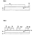
- a p-doped trough 2 with a dopant concentration of, for example, 1 x 10 17 cm -3 is formed by implantation in a substrate 1 made of, for example, p-doped monocrystalline silicon with a basic dopant concentration of 2 ⁇ 10 15 cm -3 (see Figure 2).
- the depth of the p-doped well 12 is, for example, 1 ⁇ m.
- a threshold voltage implantation is carried out, for example, with boron with a dose of 3 ⁇ 10 12 cm -2 and an energy of 25 keV (not shown).
- a programming mask 13 is then formed, for example as a photoresist, by photolithographic process steps.
- An implantation with n-doping ions for example As with a dose of 1 x 10 14 cm -2 and an energy of 40 keV, is carried out, in which the selection switch is programmed. In this case, channel dopings 14 are generated at those points of intersection of the bit selection lines BA with the bit lines BL at which no selection transistors AT are formed.
- the first dielectric layer 15 is called Triple layer from a first silicon oxide layer with a Thickness of 3 nm, a silicon nitride layer with a Thickness of 8 nm and a second silicon oxide layer with a Formed thickness of 4 nm.
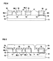
- the first word lines WL1 and the bit selection lines BA are formed, each of which is covered by a first SiO 2 structure 16 (see FIG. 3).
- the first electrode layer is formed, for example, from doped polysilicon in a layer thickness of, for example, 0.4 ⁇ m by in-situ doped deposition or undoped deposition and subsequent doping of the implantation or diffusion.
- the first electrode layer can also be formed from metal silicide and / or metal.
- the first SiO 2 layer is formed, for example, in a TEOS process in a layer thickness of 200 nm.
- the structuring takes place, for example, by anisotropic etching with CHF 3 .
- the first dielectric layer 15 is then structured by dry etching with CHF 3 .
- a further SiO 2 layer for example in a TEOS process or from phosphorus silicate glass
- spacers 17 are formed on the flanks of the first word lines WL1 and the bit selection lines BA.
- the spacers 17 have a width of approximately 50 nm. This requires a thickness of the further SiO 2 layer of 50 nm (see FIG. 4).
- Spacer etching is carried out, for example, at CHF 3 .
- a second dielectric layer 18 then becomes the entire surface generated (see Figure 5).
- the second dielectric Layer 18 is like the first dielectric layer 15 as Triple layer made of silicon oxide, silicon nitride and silicon oxide educated. The layer thicknesses correspond to those in the first dielectric layer 15.
- a second electrode layer is applied over the entire surface 19 from, for example, n-doped polysilicon, metal silicide and / or metal formed.
- the second electrode layer 19 is formed in a layer thickness of 0.4 ⁇ m. It fills the Spaces between adjacent word lines WL1 completely on.
- the second word lines WL2 are then formed by structuring the second electrode layer 19.
- the second electrode layer 19 is structured by isotropic etching back, for example using CF 4 / O 2 .
- the surface of the second dielectric layer 18 acts as an etch stop. The etching is continued until the portion of the second electrode layer 19 which is arranged between the bit selection lines BA and the first word line WL1 adjacent to the bit selection lines BA is completely removed. This takes advantage of the fact that the distance between the bit selection lines BA and the first word line WL1 adjacent to them is greater than the distance between adjacent word lines WL1 (see FIG. 6).
- the upper region of the second dielectric layer 18 is subsequently removed, for example with hydrofluoric acid, so that the surface of the spacers 17 is partially exposed.
- the spacers 17 are then selectively removed to form doped polysilicon.
- An implantation with n-doping ions, for example with As, is carried out with a dose of 1 ⁇ 10 12 to 1 ⁇ 10 13 cm -2 and an energy of 20 keV.
- diffusion can also take place. It is useful to do this by removing the Spacer 17 resulting gaps with phosphor silicate glass, the for example as an intermediate oxide is used to replenish and the dopant by diffusion into the p-doped well 12 bring in.
- the doping can also be achieved by outdiffusion the spacers 17 take place if they are made of phosphorus silicate glass are formed.
- An implantation is then carried out, for example with As, with a dopant concentration of 5 ⁇ 10 15 cm -2 and an energy of 80 keV, in which the first doped regions D1, the second doped regions D2 and source / drain regions 20 for the selection transistors AT are formed (see Figure 7 and Figure 1).
- the Word lines WL1, WL2 are structured so that they have word line expansion WLA on which Word line contacts WLK to transverse aluminum tracks AL are formed (see Figure 8).
- the Word lines WL1, WL2 formed so that they in the area of Word line contact WLK be widened on one side.
- the Word line expansion WLA arises from the fact that it is one-sided Widenings on opposite sides the word line WL1, WL2 is arranged. Before and after word line expansion WLA is the width of the word line WL1, WL2 less than in the area of word line expansion WLA. Furthermore, the center of the word line WL1, WL2 is before and offset against each other behind the word line expansion WLA.
- the word line widenings WLA from neighboring word lines WL1, WL2 are staggered.
- the Width of the word lines WL1, WL2 is outside the word line widenings WLA about half the value in the range the word line expansion WLA. That way a secure opening of the contact holes to form the word line contacts WLK guarantees without the space requirement of the To enlarge word lines too much.
- the word line widenings WLA effect an additional one Space requirements in the direction of the width of the word lines WL1, WL2 of about one word line per segment.
- a segment includes, for example, 32 to 128 word lines.
- the memory cell arrangement is made by depositing an intermediate oxide, Contact hole etching and application and structuring finished with a metal layer. These well-known Process steps are not shown.
- a memory cell arrangement comprises first word lines WL1 'and second word lines WL2', which are arranged alternately (see FIG. 9). The distance between the word lines WL1 'and the adjacent second word lines WL2' is less than the width of the word lines WL1 ', WL2'.
- Bit lines BL ' which each comprise a first doped region D1', a second doped region D2 ', a gate dielectric and the word lines WL1', WL2 'arranged in between and acting as gate electrodes, run transverse to the word lines WL1', WL2 '.
- the area in which the word lines WL1 ', WL2' and the bit lines BL 'intersect corresponds to the cell array of the memory cell arrangement.
- the distance between the centers of adjacent first word lines WL1 'and second word lines WL2' is, for example, a minimum structure size F.
- the distance between the centers of adjacent bit lines BL ' is also a minimum structure size F. This means that the space required per memory cell, which as an intersection, is one of the Word lines WL1 ', WL2' is defined with one of the bit lines BL ', 1 F 2 .
- a decoder is arranged outside the cell field Bit selection lines running transversely to the bit lines BL ' BA 'includes. Selection transistors are on the bit selection lines BA ' AT of the decoder can be controlled. At crossing points the bit selection lines BA 'with the bit lines BL', on which no selection transistors AT 'are arranged below a channel doping is provided for the bit selection lines BA ', by which the parasitic arising at this crossing point MOS transistor has such a threshold voltage, that it is independent of that on the corresponding bit selection line BA 'applied level, conducts. This is preferably Threshold voltage negative.
- Adjacent bit lines BL ' are over one Diffusion contact DI 'and a metallization M' with each other and connected to a node K '.
- a p-doped well 22 is formed, for example, by implantation with boron in a substrate 21, for example in a p-doped monocrystalline silicon wafer with a dopant concentration of 2 ⁇ 10 15 cm -3 or in the silicon layer of an SOI substrate.
- the p-doped well 22 has a dopant concentration of, for example, 1 ⁇ 10 17 cm -3 and a depth of, for example, 1 ⁇ m (see FIG. 10).
- a scatter oxide is then applied in a thickness of, for example, 5 nm (not shown).
- a boron implantation is carried out over the entire area, for example with a dose of 3 x 10 12 cm -2 and an energy of 25 keV.
- An implantation with n-doping ions follows for programming the transistors of the decoder, which are arranged between adjacent trenches. The implantation takes place, for example, with As at an energy of 40 keV and a dose of 1 x 10 14 cm -2 . Channel doping 241 is formed.
- a TEOS hard mask 25 with a thickness of, for example, 300 nm is produced by deposition of a TEOS-SiO 2 layer and subsequent structuring (see FIG. 11, in which the section denoted by CC in FIG Semiconductor substrate is shown).
- anisotropic etching for example with HBr using the TEOS hard mask 25 as an etching mask, strip-shaped trenches 26 are etched into the substrate.
- the trenches 26 have a depth of 0.6 ⁇ m (see FIG. 11).
- SiO 2 spacers 27 are formed on the side walls of the trenches by depositing an SiO 2 layer in a thickness of 50 nm and etching back with CHF 3 .
- An implantation for setting the threshold voltage of MOS transistors to be produced on the bottom of the trenches 26 is then carried out over the entire area.
- the implantation is carried out, for example, with boron with an energy of 25 keV and a dose of 3 x 10 12 cm -2 .
- a second programming mask 232 is subsequently formed, for example, from photoresist with the aid of photolithographic process steps.
- Channel doping 242 is formed by implantation with n-doping ions, for example with As with an energy of 40 keV and a dose of 1 ⁇ 10 14 cm -2 .
- MOS transistors of the decoder which are arranged at the bottom of the trenches 26, are programmed (see FIG. 12, which represents the section designated BB in FIG. 9 parallel to one of the trenches 26 at the bottom of the trench 26).
- the second programming mask 232 completely covers the cell field.
- SiO 2 spacers 28 are formed on the side walls of the trenches.
- a TEOS-SiO 2 layer is deposited in a layer thickness of 80 nm and etched with CHF 3 (see FIG. 14, in which the section CC is shown).
- a first dielectric layer 29 is formed over the entire surface.
- the first dielectric layer 29 is formed as a triple layer, which has a first SiO 2 layer with a thickness of 3 nm, an Si 3 N 4 layer with a thickness of 8 nm and a second SiO 2 layer with a thickness of 4 nm includes (see Figure 13 which shows the section AA, Figure 14 which shows the section CC and Figure 15 which shows the section BB).
- a first electrode layer and a TEOS-SiO 2 layer are then deposited in order to form the first word lines WL1 'and a silicon oxide layer 30 covering them.
- the first electrode layer is formed, for example, by in-situ doped deposition of polysilicon or by undoped deposition of polysilicon and subsequent doping by implantation or diffusion in a layer thickness of 0.4 ⁇ m.
- the TEOS-SiO 2 layer 30 is formed in a layer thickness of 200 nm.
- the structuring takes place, for example, at CHF 3 .
- the first dielectric layer 29 is then structured (see FIG. 16, in which section AA is shown, and FIG. 17, in which section BB is shown).
- an insulating layer for example made of TEOS-SiO 2 or phosphorus silicate glass, and anisotropic etching back, spacers 31 are formed on the flanks of the first word lines WL1 '. The etching back takes place, for example, at CHF 3 .
- a sacrificial layer made of silicon oxide (so-called sacrificial oxide) is then produced and etched off (not shown).
- a second dielectric layer 32 is then applied over the entire surface (see FIG. 18 in which section AA is shown and FIG. 19 in which section BB is shown).
- the second dielectric layer 32 is formed, for example, as a triple layer with a first SiO 2 layer, an Si 3 N 4 layer and a second SiO 2 layer. The thicknesses of these layers correspond to the thicknesses in the first dielectric layer 29.
- a second electrode layer 33 is deposited thereon.
- the second electrode layer 33 is made of doped, for example Polysilicon formed in a layer thickness of 0.4 microns. As a result, it fills the gaps between adjacent first ones Word lines WL1 'fully open.
- the second electrode layer 33 is, for example, by in situ doped deposition of n-doped polysilicon or by undoped Deposition of polysilicon and subsequent doping formed by implantation or diffusion.
- the second word lines WL2 ' are formed by isotropically etching back the second electrode layer 33 selectively with respect to the second dielectric layer 32.
- the etching is carried out, for example, with CF 4 / O 2 .
- the etch is coated so that the surface of the second dielectric layer 32 is exposed between adjacent trenches and between the bit selection lines BA 'and the first word line WL1' adjacent to them.
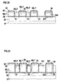
- an etching residue 331 remains on the trench bottom between the bit selection lines BA 'and the first word line WL1' adjacent to them (see FIG. 20, in which the section AA between adjacent trenches is shown, and FIG. 21, in which the section BB on the trench bottom is shown) .
- a photoresist mask 34 is then formed, which covers the cell field.
- Anisotropic etching removes the etching residue 331 on the trench bottom between the cell array and the bit selection lines BA '.
- the etching back takes place, for example, with HBr / Cl 2 (see FIG. 22, in which the section BB is shown).
- an implantation with, for example, n-doping ions is carried out to form the first doped regions D1 ', the second doped regions D2', the diffusion contact DI 'and the source / drain regions 35 of the MOS transistors of the decoder (See FIG. 9, FIG. 23, in which section AA is shown and FIG. 24, in section BB is shown).
- the implantation takes place, for example, with As with an energy of 80 keV and a dose of 5 x 10 15 cm -2 .
- the memory cell arrangement is made by depositing an intermediate oxide, Contact hole etching and application and structuring finished with a metal layer. These well-known Process steps are not shown.
- the invention is not based on the exemplary embodiments described limited.
- the conductivity types n and p are interchanged.
- the first dielectric layer 15, 29 and the second dielectric layer 18, 32 in each case a multiple layer in which at least one layer is provided which has an increased charge carrier cross-section in comparison with at least one further layer in the multiple layer has to be used from other materials, the layer with the increased charge carrier cross-section consisting for example of Si 3 N 4 , TA 2 O 5 , Al 2 O 3 or TiO 2 and the adjacent layer of SiO 2 , Si 3 N 4 or Al 2 O 3 exist.
- the first dielectric layer 15, 29 and the second dielectric layer 18, 32 can contain a dielectric layer, for example made of SiO 2 , in which foreign atoms, for example W, Pt, Cr, Ni, Pd, or Ir, are embedded. The embedded foreign atoms can be introduced by implantation, by addition during oxidation or by diffusion.
- the programming of the memory cell arrangement is carried out by Filling the traps in the first dielectric layer 15, 29 or the second dielectric layer 18, 32 by means of Injection of electrons. This will increase the threshold voltage, at which below the respective word line, which as Gate electrode acts, forms a conductive channel, increased.
- the respective value of the threshold voltage increase can be over Time and size of the voltage applied during programming to adjust.
- the programming of the memory cell arrangement can both through Fowler-Nordheim tunneling of electrons as well Hot electron injection takes place.
- the memory cell to be programmed is selected via the associated word line and bit line.
- the bit line of the memory cell is set to a low potential, for example to 0 volts.
- the other bit lines are raised to a potential VBL, which is dimensioned such that V pr - V BL is clearly below the programming voltage V pr .
- the other word lines are raised to a potential V WL greater than or equal to V BL + V T , where V T means the threshold voltage.
- the memory cells are interconnected in a NAND configuration. They can therefore be wired so that no drain current flows through the memory cells. This has the advantage that the entire programming process is very poor in performance.
- the saturation voltage must be applied to the MOS transistor to be programmed.
- the word line assigned to the memory cell is set to a potential at which the MOS transistor is in saturation mode.
- V BL V WLpr / 2.
- the saturation operation at high voltage produces hot electrons in the channel region of the MOS transistor of the selected memory cell, some of which are injected into the gate dielectric. The electrons are trapped in the gate dielectric and increase the threshold voltage of the MOS transistor.
- the threshold voltage of the respective MOS transistor is specifically changed in this way.
- the memory cell is operated in a "NAND" architecture. That is, in a row of memory cells are the unselected Word lines WL1, WL2 or WL1 ', WL2' with one Voltage applied at which the channel area conducts independently of the charge present in the gate dielectric. Becomes programmed the memory cell array to have two different ones Has threshold voltage values, then the applied voltage to selected gate electrode, between the first threshold voltage value and the second Threshold voltage value. It is assessed whether there is a current flows over the memory cell row.
Claims (16)
- Dispositif de cellules de mémoire,dans lequel plusieurs lignes de cellules de mémoire sont disposées dans un substrat (11) semi-conducteur,dans lequel des lignes de cellules de mémoire voisines sont isolées les unes des autres,dans lequel les lignes de cellules de mémoire ne comportent au début et à la fin respectivement qu'une première région D1 dopée correspondant à une région de source/drain et une deuxième région D2 dopée correspondant à une région de source/drain, un diélectrique (15, 18) de grille, qui contient un matériau à piège de porteur de charge, et plusieurs électrodes (WL1, WL2) de grille disposés côte-à-côte étant disposés entre les régions dopées sur une surface principale du substrat (11) semi-conducteur,dans lequel la distance entre des électrodes (WL1, WL2) de grille voisines est inférieure aux dimensions des électrodes (WL1, WL2) de grille parallèlement à la ligne de liaison entre la première région (D1) dopée et la deuxième région (D2) dopée.
- Dispositif de cellules de mémoire suivant la revendication 1,dans lequel il est prévu dans la surface principale du substrat (21) semi-conducteur des sillons (26) parallèles en forme de bande,dans lequel les lignes de cellules de mémoire sont disposées chaque fois alternativement au fond des sillons (26) et entre les sillons (26) voisins, sur la surface principale.
- Dispositif de cellules de mémoire suivant la revendication 1,
dans lequel il est prévu des sillons (T) isolants dans le substrat (11) semi-conducteur pour l'isolement entre des lignes de cellules de mémoire voisines. - Dispositif de cellules de mémoire suivant l'une des revendications 1 à 3 dans lequel, le diélectrique de grille comprend chaque fois une multicouche diélectrique comportant au moins une couche qui a, comparée à au moins une autre couche, une section transversale accrue de piégeage de porteurs de charge.
- Dispositif de cellules de mémoire suivant la revendication 4,dans lequel la couche ayant la section transversale accrue de piégeage de porteurs de charge comprend au moins une des substances Si3N4, TA2O5, Al2O3 ou TiO2,dans lequel la couche supplémentaire comporte au moins l'une des substances SiO2, Si3N4 ou Al2O3.
- Dispositif de cellules de mémoire suivant l'une des revendications 1 à 3, dans lequel le diélectrique de grille comprend chaque fois une couche diélectrique comportant des atomes étrangers incorporés, les atomes étrangers incorporés ayant, comparés à la couche diélectrique, une section transversale accrue de piégeage de porteurs de charge.
- Dispositif de cellules de mémoire suivant la revendication 3,dans lequel la couche diélectrique contient du SiO2,dans lequel les atomes étrangers incorporés contiennent au moins l'un des éléments W, Pt, Cr, Ni, Pd, ou Ir.
- Procédé pour produire un dispositif de cellules de mémoiredans lequel on produit dans un substrat (11) semi-conducteur plusieurs lignes de cellules de mémoire qui sont isolées les unes des autres,dans lequel on forme pour chaque ligne de cellules de mémoire, au début et à la fin de la ligne de mémoire associée, dans le substrat (11) semi-conducteur, seulement une première région (D1) dopée correspondant à une région de source/drain et une deuxième région (D2) dopée correspondant à une région de source/drain,dans lequel on produit entre la première région (D1) dopée et la deuxième région (D2) dopée, sur une surface principale du substrat (11) semi-conducteur, un diélectrique (15, 18) de grille qui est en un matériau comportant des pièges de porteurs de charge et plusieurs électrodes de grille disposées côte-à-côte, de telle manière que la distance entre des électrodes (WL1, WL2) de grille voisines est inférieure aux dimensions des électrodes (WL1, WL2) de grille parallèlement à la ligne de liaison entre la première région (D1) dopée et la deuxième région (D2) dopée.
- Procédé suivant la revendication 8,dans lequel on forme le diélectrique (15, 18) de grille chaque fois en triple couche comportant au moins une couche qui a, comparé à au moins une autre couche, une section transversale accrue de piégeage de porteurs de charge.
- Procédé suivant la revendication 9,dans lequel la couche à section transversale accrue de piégeage de porteurs de charge comprend au moins l'une des substances Si3N4, Ta2O5, Al2O3 ou TiO2,dans lequel la couche supplémentaire comprend au moins une des substances SiO2, Si3N4, ou Al2O3.
- Procédé suivant la revendication 9,dans lequel on forme le diélectrique (15, 18) de grille chaque fois en couche diélectrique à atomes étrangers incorporés, les atomes étrangers incorporés ayant, comparés à la couche diélectrique, une section transversale accrue de piégeage de porteurs de charge.
- Procédé suivant la revendication 11,dans lequel la couche diélectrique comprend du SiO2,dans lequel les atomes étrangers incorporés contiennent au moins l'un des éléments W, Pt, Cr, Ni, Pd ou Ir.
- Procédé suivant l'une des revendications 8 à 12,dans lequel on forme une première couche (15) diélectrique,dans lequel on produit une première couche d'électrodes et on la structure pour former de premières électrodes (WL1) de grille,dans lequel on forme des espaceurs (17) sur les flancs des premières électrodes (WL1) de grille,dans lequel on forme une deuxième couche (18) diélectrique,dans lequel on produit et on structure, pour former des deuxièmes électrodes (WL2) de grille, une deuxième couche (19) d'électrode ayant un revêtement d'arête sensiblement conforme.
- Procédé suivant la revendication 13,dans lequel on enlève les espaceurs (17) entre les premières électrodes (WL1) de grille et les deuxièmes électrodes (WL2) de grille de manière sélective par rapport aux premières électrodes (WL1) de grille et aux deuxièmes électrodes (WL2) de grille,dans lequel on module par un contre-dopage le dopage du substrat semi-conducteur dans la zone entre les premières électrodes (WL1) de grille et les deuxièmes électrodes (WL2) de grille.
- Procédé suivant l'une des revendications 12 à 14,
dans lequel on forme dans la surface principale du substrat (11) semi-conducteur des sillons (T) isolants en forme de bande qui sont disposés chaque fois entre des lignes de cellules de mémoire voisines. - Procédé suivant l'une des revendications 12 à 14,dans lequel on forme dans la surface principale du substrat (21) semi-conducteur des sillons (26) en forme de bande sensiblement parallèles,dans lequel on forme les lignes de cellules de mémoire chaque fois alternativement au fond des sillons (26) et sur la surface principale entre des sillons (26) voisins.
Applications Claiming Priority (3)
| Application Number | Priority Date | Filing Date | Title |
|---|---|---|---|
| DE19652547 | 1996-12-17 | ||
| DE19652547A DE19652547C2 (de) | 1996-12-17 | 1996-12-17 | Speicherzellenanordnung mit Grabenstruktur und einem Gatedielektrikum, das ein Material mit Ladungsträger-Haftstellen enthält, und Verfahren zu deren Herstellung |
| PCT/DE1997/002730 WO1998027594A1 (fr) | 1996-12-17 | 1997-11-20 | Agencement de cellules de memoire et son procede de fabrication |
Publications (2)
| Publication Number | Publication Date |
|---|---|
| EP0946985A1 EP0946985A1 (fr) | 1999-10-06 |
| EP0946985B1 true EP0946985B1 (fr) | 2001-08-16 |
Family
ID=7815048
Family Applications (1)
| Application Number | Title | Priority Date | Filing Date |
|---|---|---|---|
| EP97951797A Expired - Lifetime EP0946985B1 (fr) | 1996-12-17 | 1997-11-20 | Agencement de cellules de memoire et son procede de fabrication |
Country Status (8)
| Country | Link |
|---|---|
| US (1) | US6445046B1 (fr) |
| EP (1) | EP0946985B1 (fr) |
| JP (1) | JP2001506410A (fr) |
| KR (1) | KR20000057583A (fr) |
| CN (1) | CN1139131C (fr) |
| DE (2) | DE19652547C2 (fr) |
| TW (1) | TW363274B (fr) |
| WO (1) | WO1998027594A1 (fr) |
Families Citing this family (17)
| Publication number | Priority date | Publication date | Assignee | Title |
|---|---|---|---|---|
| US6947471B1 (en) | 1998-01-05 | 2005-09-20 | Intel Corporation | Method for using encoded spreading codes to achieve high bit densities in a direct-sequence spread spectrum communication system |
| KR100699608B1 (ko) | 1999-03-09 | 2007-03-23 | 코닌클리즈케 필립스 일렉트로닉스 엔.브이. | 비휘발성 메모리를 포함하는 반도체 디바이스 |
| US6284637B1 (en) * | 1999-03-29 | 2001-09-04 | Chartered Semiconductor Manufacturing Ltd. | Method to fabricate a floating gate with a sloping sidewall for a flash memory |
| DE19955602A1 (de) * | 1999-11-18 | 2001-05-31 | Infineon Technologies Ag | Nichtflüchtige Halbleiter- Speicherzelle sowie Verfahren zu deren Herstellung |
| JP4730999B2 (ja) * | 2000-03-10 | 2011-07-20 | スパンション エルエルシー | 不揮発性メモリの製造方法 |
| DE10051483A1 (de) * | 2000-10-17 | 2002-05-02 | Infineon Technologies Ag | Nichtflüchtige Halbleiterspeicherzellenanordnung und Verfahren zu deren Herstellung |
| US6580120B2 (en) * | 2001-06-07 | 2003-06-17 | Interuniversitair Microelektronica Centrum (Imec Vzw) | Two bit non-volatile electrically erasable and programmable memory structure, a process for producing said memory structure and methods for programming, reading and erasing said memory structure |
| JP2003031700A (ja) * | 2001-07-12 | 2003-01-31 | Sony Corp | 不揮発性半導体記憶装置、その動作方法および製造方法 |
| JP2003078045A (ja) * | 2001-09-03 | 2003-03-14 | Sony Corp | 不揮発性半導体記憶装置およびその製造方法 |
| JP2005056889A (ja) * | 2003-08-04 | 2005-03-03 | Renesas Technology Corp | 半導体記憶装置およびその製造方法 |
| KR100540478B1 (ko) * | 2004-03-22 | 2006-01-11 | 주식회사 하이닉스반도체 | 전하 트랩을 갖는 게이트유전체를 포함한 휘발성 메모리셀 트랜지스터 및 그 제조 방법 |
| US7244638B2 (en) * | 2005-09-30 | 2007-07-17 | Infineon Technologies Ag | Semiconductor memory device and method of production |
| CN101136373B (zh) * | 2006-08-31 | 2010-11-17 | 旺宏电子股份有限公司 | 非易失性存储器的制造方法 |
| JP2011171755A (ja) * | 2011-04-15 | 2011-09-01 | Renesas Electronics Corp | 半導体装置 |
| US11469235B2 (en) * | 2019-09-27 | 2022-10-11 | Nanya Technology Corporation | Semiconductor device and method for fabricating the same |
| CN111933644B (zh) * | 2020-08-10 | 2024-02-02 | 合肥晶合集成电路股份有限公司 | 闪存单元及其制造方法 |
| CN116156890B (zh) * | 2023-04-19 | 2023-07-18 | 杭州领开半导体技术有限公司 | Nor闪存阵列的制作方法 |
Family Cites Families (16)
| Publication number | Priority date | Publication date | Assignee | Title |
|---|---|---|---|---|
| US3731163A (en) | 1972-03-22 | 1973-05-01 | United Aircraft Corp | Low voltage charge storage memory element |
| US4047974A (en) | 1975-12-30 | 1977-09-13 | Hughes Aircraft Company | Process for fabricating non-volatile field effect semiconductor memory structure utilizing implanted ions to induce trapping states |
| JPH0321069A (ja) * | 1989-06-19 | 1991-01-29 | Matsushita Electron Corp | 半導体装置の製造方法 |
| US5200355A (en) * | 1990-12-10 | 1993-04-06 | Samsung Electronics Co., Ltd. | Method for manufacturing a mask read only memory device |
| JP2655765B2 (ja) * | 1991-05-29 | 1997-09-24 | ローム株式会社 | 半導体装置 |
| JPH0529584A (ja) * | 1991-07-25 | 1993-02-05 | Nec Kyushu Ltd | 読み出し専用半導体メモリ |
| JPH05251669A (ja) * | 1992-03-06 | 1993-09-28 | Matsushita Electron Corp | 半導体記憶装置およびその書き換え方法 |
| US6310373B1 (en) * | 1992-10-23 | 2001-10-30 | Symetrix Corporation | Metal insulator semiconductor structure with polarization-compatible buffer layer |
| JP2795107B2 (ja) * | 1992-11-26 | 1998-09-10 | 日本電気株式会社 | 半導体装置の製造方法 |
| US5393233A (en) * | 1993-07-14 | 1995-02-28 | United Microelectronics Corporation | Process for fabricating double poly high density buried bit line mask ROM |
| JPH07254651A (ja) * | 1994-03-16 | 1995-10-03 | Toshiba Corp | 半導体集積回路装置 |
| DE19510042C2 (de) * | 1995-03-20 | 1997-01-23 | Siemens Ag | Festwert-Speicherzellenanordnung und Verfahren zu deren Herstellung |
| JP3171122B2 (ja) * | 1995-11-27 | 2001-05-28 | ソニー株式会社 | 半導体記憶装置および半導体記憶装置の情報読出方法 |
| DE19600422C1 (de) * | 1996-01-08 | 1997-08-21 | Siemens Ag | Elektrisch programmierbare Speicherzellenanordnung und Verfahren zu deren Herstellung |
| US5814853A (en) * | 1996-01-22 | 1998-09-29 | Advanced Micro Devices, Inc. | Sourceless floating gate memory device and method of storing data |
| US5768192A (en) * | 1996-07-23 | 1998-06-16 | Saifun Semiconductors, Ltd. | Non-volatile semiconductor memory cell utilizing asymmetrical charge trapping |
-
1996
- 1996-12-17 DE DE19652547A patent/DE19652547C2/de not_active Expired - Fee Related
-
1997
- 1997-11-19 TW TW086117262A patent/TW363274B/zh active
- 1997-11-20 WO PCT/DE1997/002730 patent/WO1998027594A1/fr active IP Right Grant
- 1997-11-20 DE DE59704333T patent/DE59704333D1/de not_active Expired - Lifetime
- 1997-11-20 KR KR1019990705348A patent/KR20000057583A/ko active IP Right Grant
- 1997-11-20 US US09/331,034 patent/US6445046B1/en not_active Expired - Fee Related
- 1997-11-20 JP JP52716898A patent/JP2001506410A/ja active Pending
- 1997-11-20 CN CNB971807205A patent/CN1139131C/zh not_active Expired - Fee Related
- 1997-11-20 EP EP97951797A patent/EP0946985B1/fr not_active Expired - Lifetime
Also Published As
| Publication number | Publication date |
|---|---|
| CN1240536A (zh) | 2000-01-05 |
| DE59704333D1 (de) | 2001-09-20 |
| WO1998027594A1 (fr) | 1998-06-25 |
| TW363274B (en) | 1999-07-01 |
| JP2001506410A (ja) | 2001-05-15 |
| DE19652547A1 (de) | 1998-06-18 |
| US6445046B1 (en) | 2002-09-03 |
| EP0946985A1 (fr) | 1999-10-06 |
| CN1139131C (zh) | 2004-02-18 |
| KR20000057583A (ko) | 2000-09-25 |
| DE19652547C2 (de) | 2002-04-25 |
Similar Documents
| Publication | Publication Date | Title |
|---|---|---|
| DE19600423C2 (de) | Elektrisch programmierbare Speicherzellenanordnung und Verfahren zu deren Herstellung | |
| DE19603810C1 (de) | Speicherzellenanordnung und Verfahren zu deren Herstellung | |
| EP0783180B1 (fr) | Ensemble de cellules mémoire électriquement programmable et procédé de fabrication | |
| DE19609678C2 (de) | Speicherzellenanordnung mit streifenförmigen, parallel verlaufenden Gräben und vertikalen MOS-Transistoren und Verfahren zu deren Herstellung | |
| DE10194689B4 (de) | Nichtflüchtige Halbleiterspeicher mit zwei Speichereinheiten und Verfahren zu deren Herstellung | |
| DE102004060171B4 (de) | Charge-trapping-Speicherzelle und deren Herstellungsverfahren | |
| DE19524478C2 (de) | Verfahren zur Herstellung einer Festwertspeicherzellenanordnung | |
| DE4404270C2 (de) | Halbleiterspeichervorrichtungen, die Information elektrisch schreiben und löschen können und Verfahren zur Herstellung derselben | |
| DE19514834C1 (de) | Festwertspeicherzellenanordnung und Verfahren zu deren Herstellung | |
| EP0946985B1 (fr) | Agencement de cellules de memoire et son procede de fabrication | |
| DE19808182C1 (de) | Elektrisch programmierbare Speicherzellenanordnung und ein Verfahren zu deren Herstellung | |
| DE10220923B4 (de) | Verfahren zur Herstellung eines nicht-flüchtigen Flash-Halbleiterspeichers | |
| DE4219854A1 (de) | Elektrisch loeschbare und programmierbare halbleiterspeichereinrichtung und verfahren zur herstellung derselben | |
| DE102006005679A1 (de) | Halbleiterbauelement mit einer Transistorstruktur und Verfahren zur Herstellung desselben | |
| EP0838092B1 (fr) | Systeme de cellules de memoire morte programmable effa able electriquement et procede de fabrication dudit systeme | |
| DE102008021396A1 (de) | Speicherzelle | |
| DE10258194B4 (de) | Halbleiterspeicher mit Charge-trapping-Speicherzellen und Herstellungsverfahren | |
| DE19807010B4 (de) | Verfahren zur Herstellung einer nichtflüchtigen Speichereinrichtung | |
| EP0815594B1 (fr) | Systeme de cellules de memoire morte et son procede de realisation | |
| DE4123158C2 (de) | Verfahren zur Herstellung von zueinander parallel ausgerichteten Leiterschichtabschnitten | |
| DE19646419C1 (de) | Verfahren zur Herstellung einer elektrisch schreib- und löschbaren Festwertspeicherzellenanordnung | |
| DE19617646C2 (de) | Speicherzellenanordnung und ein Verfahren zu deren Herstellung | |
| EP0865667B1 (fr) | Memoire morte et son procede de production | |
| DE102006026941B3 (de) | Speicherzellenfeld mit nichtflüchtigen Speicherzellen und Verfahren zu dessen Herstellung | |
| DE19653107C2 (de) | Verfahren zur Herstellung einer Speicherzellenanordnung |
Legal Events
| Date | Code | Title | Description |
|---|---|---|---|
| PUAI | Public reference made under article 153(3) epc to a published international application that has entered the european phase |
Free format text: ORIGINAL CODE: 0009012 |
|
| 17P | Request for examination filed |
Effective date: 19990607 |
|
| AK | Designated contracting states |
Kind code of ref document: A1 Designated state(s): DE FR GB IT |
|
| 17Q | First examination report despatched |
Effective date: 19991103 |
|
| GRAG | Despatch of communication of intention to grant |
Free format text: ORIGINAL CODE: EPIDOS AGRA |
|
| GRAG | Despatch of communication of intention to grant |
Free format text: ORIGINAL CODE: EPIDOS AGRA |
|
| GRAH | Despatch of communication of intention to grant a patent |
Free format text: ORIGINAL CODE: EPIDOS IGRA |
|
| RAP1 | Party data changed (applicant data changed or rights of an application transferred) |
Owner name: INFINEON TECHNOLOGIES AG |
|
| GRAH | Despatch of communication of intention to grant a patent |
Free format text: ORIGINAL CODE: EPIDOS IGRA |
|
| GRAH | Despatch of communication of intention to grant a patent |
Free format text: ORIGINAL CODE: EPIDOS IGRA |
|
| GRAA | (expected) grant |
Free format text: ORIGINAL CODE: 0009210 |
|
| AK | Designated contracting states |
Kind code of ref document: B1 Designated state(s): DE FR GB IT |
|
| REF | Corresponds to: |
Ref document number: 59704333 Country of ref document: DE Date of ref document: 20010920 |
|
| GBT | Gb: translation of ep patent filed (gb section 77(6)(a)/1977) |
Effective date: 20011117 |
|
| REG | Reference to a national code |
Ref country code: GB Ref legal event code: IF02 |
|
| ET | Fr: translation filed | ||
| PLBE | No opposition filed within time limit |
Free format text: ORIGINAL CODE: 0009261 |
|
| STAA | Information on the status of an ep patent application or granted ep patent |
Free format text: STATUS: NO OPPOSITION FILED WITHIN TIME LIMIT |
|
| 26N | No opposition filed | ||
| PG25 | Lapsed in a contracting state [announced via postgrant information from national office to epo] |
Ref country code: IT Free format text: LAPSE BECAUSE OF NON-PAYMENT OF DUE FEES;WARNING: LAPSES OF ITALIAN PATENTS WITH EFFECTIVE DATE BEFORE 2007 MAY HAVE OCCURRED AT ANY TIME BEFORE 2007. THE CORRECT EFFECTIVE DATE MAY BE DIFFERENT FROM THE ONE RECORDED. Effective date: 20051120 |
|
| PGFP | Annual fee paid to national office [announced via postgrant information from national office to epo] |
Ref country code: GB Payment date: 20101118 Year of fee payment: 14 |
|
| PGFP | Annual fee paid to national office [announced via postgrant information from national office to epo] |
Ref country code: FR Payment date: 20111130 Year of fee payment: 15 |
|
| PGFP | Annual fee paid to national office [announced via postgrant information from national office to epo] |
Ref country code: DE Payment date: 20120112 Year of fee payment: 15 |
|
| GBPC | Gb: european patent ceased through non-payment of renewal fee |
Effective date: 20121120 |
|
| REG | Reference to a national code |
Ref country code: FR Ref legal event code: ST Effective date: 20130731 |
|
| REG | Reference to a national code |
Ref country code: DE Ref legal event code: R119 Ref document number: 59704333 Country of ref document: DE Effective date: 20130601 |
|
| PG25 | Lapsed in a contracting state [announced via postgrant information from national office to epo] |
Ref country code: DE Free format text: LAPSE BECAUSE OF NON-PAYMENT OF DUE FEES Effective date: 20130601 |
|
| PG25 | Lapsed in a contracting state [announced via postgrant information from national office to epo] |
Ref country code: GB Free format text: LAPSE BECAUSE OF NON-PAYMENT OF DUE FEES Effective date: 20121120 Ref country code: FR Free format text: LAPSE BECAUSE OF NON-PAYMENT OF DUE FEES Effective date: 20121130 |