EP0937618A2 - Procédé et dispositif pour contrÔler la fonction d'un système de freinage - Google Patents
Procédé et dispositif pour contrÔler la fonction d'un système de freinage Download PDFInfo
- Publication number
- EP0937618A2 EP0937618A2 EP98118809A EP98118809A EP0937618A2 EP 0937618 A2 EP0937618 A2 EP 0937618A2 EP 98118809 A EP98118809 A EP 98118809A EP 98118809 A EP98118809 A EP 98118809A EP 0937618 A2 EP0937618 A2 EP 0937618A2
- Authority
- EP
- European Patent Office
- Prior art keywords
- pressure
- brake
- wheel
- wheel brake
- reached
- Prior art date
- Legal status (The legal status is an assumption and is not a legal conclusion. Google has not performed a legal analysis and makes no representation as to the accuracy of the status listed.)
- Granted
Links
Images


Classifications
-
- B—PERFORMING OPERATIONS; TRANSPORTING
- B60—VEHICLES IN GENERAL
- B60T—VEHICLE BRAKE CONTROL SYSTEMS OR PARTS THEREOF; BRAKE CONTROL SYSTEMS OR PARTS THEREOF, IN GENERAL; ARRANGEMENT OF BRAKING ELEMENTS ON VEHICLES IN GENERAL; PORTABLE DEVICES FOR PREVENTING UNWANTED MOVEMENT OF VEHICLES; VEHICLE MODIFICATIONS TO FACILITATE COOLING OF BRAKES
- B60T17/00—Component parts, details, or accessories of power brake systems not covered by groups B60T8/00, B60T13/00 or B60T15/00, or presenting other characteristic features
- B60T17/18—Safety devices; Monitoring
- B60T17/22—Devices for monitoring or checking brake systems; Signal devices
- B60T17/221—Procedure or apparatus for checking or keeping in a correct functioning condition of brake systems
-
- B—PERFORMING OPERATIONS; TRANSPORTING
- B60—VEHICLES IN GENERAL
- B60T—VEHICLE BRAKE CONTROL SYSTEMS OR PARTS THEREOF; BRAKE CONTROL SYSTEMS OR PARTS THEREOF, IN GENERAL; ARRANGEMENT OF BRAKING ELEMENTS ON VEHICLES IN GENERAL; PORTABLE DEVICES FOR PREVENTING UNWANTED MOVEMENT OF VEHICLES; VEHICLE MODIFICATIONS TO FACILITATE COOLING OF BRAKES
- B60T8/00—Arrangements for adjusting wheel-braking force to meet varying vehicular or ground-surface conditions, e.g. limiting or varying distribution of braking force
- B60T8/32—Arrangements for adjusting wheel-braking force to meet varying vehicular or ground-surface conditions, e.g. limiting or varying distribution of braking force responsive to a speed condition, e.g. acceleration or deceleration
- B60T8/34—Arrangements for adjusting wheel-braking force to meet varying vehicular or ground-surface conditions, e.g. limiting or varying distribution of braking force responsive to a speed condition, e.g. acceleration or deceleration having a fluid pressure regulator responsive to a speed condition
- B60T8/40—Arrangements for adjusting wheel-braking force to meet varying vehicular or ground-surface conditions, e.g. limiting or varying distribution of braking force responsive to a speed condition, e.g. acceleration or deceleration having a fluid pressure regulator responsive to a speed condition comprising an additional fluid circuit including fluid pressurising means for modifying the pressure of the braking fluid, e.g. including wheel driven pumps for detecting a speed condition, or pumps which are controlled by means independent of the braking system
- B60T8/4072—Systems in which a driver input signal is used as a control signal for the additional fluid circuit which is normally used for braking
- B60T8/4081—Systems with stroke simulating devices for driver input
- B60T8/4086—Systems with stroke simulating devices for driver input the stroke simulating device being connected to, or integrated in the driver input device
-
- B—PERFORMING OPERATIONS; TRANSPORTING
- B60—VEHICLES IN GENERAL
- B60T—VEHICLE BRAKE CONTROL SYSTEMS OR PARTS THEREOF; BRAKE CONTROL SYSTEMS OR PARTS THEREOF, IN GENERAL; ARRANGEMENT OF BRAKING ELEMENTS ON VEHICLES IN GENERAL; PORTABLE DEVICES FOR PREVENTING UNWANTED MOVEMENT OF VEHICLES; VEHICLE MODIFICATIONS TO FACILITATE COOLING OF BRAKES
- B60T8/00—Arrangements for adjusting wheel-braking force to meet varying vehicular or ground-surface conditions, e.g. limiting or varying distribution of braking force
- B60T8/32—Arrangements for adjusting wheel-braking force to meet varying vehicular or ground-surface conditions, e.g. limiting or varying distribution of braking force responsive to a speed condition, e.g. acceleration or deceleration
- B60T8/88—Arrangements for adjusting wheel-braking force to meet varying vehicular or ground-surface conditions, e.g. limiting or varying distribution of braking force responsive to a speed condition, e.g. acceleration or deceleration with failure responsive means, i.e. means for detecting and indicating faulty operation of the speed responsive control means
- B60T8/885—Arrangements for adjusting wheel-braking force to meet varying vehicular or ground-surface conditions, e.g. limiting or varying distribution of braking force responsive to a speed condition, e.g. acceleration or deceleration with failure responsive means, i.e. means for detecting and indicating faulty operation of the speed responsive control means using electrical circuitry
-
- B—PERFORMING OPERATIONS; TRANSPORTING
- B60—VEHICLES IN GENERAL
- B60T—VEHICLE BRAKE CONTROL SYSTEMS OR PARTS THEREOF; BRAKE CONTROL SYSTEMS OR PARTS THEREOF, IN GENERAL; ARRANGEMENT OF BRAKING ELEMENTS ON VEHICLES IN GENERAL; PORTABLE DEVICES FOR PREVENTING UNWANTED MOVEMENT OF VEHICLES; VEHICLE MODIFICATIONS TO FACILITATE COOLING OF BRAKES
- B60T8/00—Arrangements for adjusting wheel-braking force to meet varying vehicular or ground-surface conditions, e.g. limiting or varying distribution of braking force
- B60T8/32—Arrangements for adjusting wheel-braking force to meet varying vehicular or ground-surface conditions, e.g. limiting or varying distribution of braking force responsive to a speed condition, e.g. acceleration or deceleration
- B60T8/88—Arrangements for adjusting wheel-braking force to meet varying vehicular or ground-surface conditions, e.g. limiting or varying distribution of braking force responsive to a speed condition, e.g. acceleration or deceleration with failure responsive means, i.e. means for detecting and indicating faulty operation of the speed responsive control means
- B60T8/90—Arrangements for adjusting wheel-braking force to meet varying vehicular or ground-surface conditions, e.g. limiting or varying distribution of braking force responsive to a speed condition, e.g. acceleration or deceleration with failure responsive means, i.e. means for detecting and indicating faulty operation of the speed responsive control means using a simulated speed signal to test speed responsive control means
-
- B—PERFORMING OPERATIONS; TRANSPORTING
- B60—VEHICLES IN GENERAL
- B60T—VEHICLE BRAKE CONTROL SYSTEMS OR PARTS THEREOF; BRAKE CONTROL SYSTEMS OR PARTS THEREOF, IN GENERAL; ARRANGEMENT OF BRAKING ELEMENTS ON VEHICLES IN GENERAL; PORTABLE DEVICES FOR PREVENTING UNWANTED MOVEMENT OF VEHICLES; VEHICLE MODIFICATIONS TO FACILITATE COOLING OF BRAKES
- B60T2270/00—Further aspects of brake control systems not otherwise provided for
- B60T2270/40—Failsafe aspects of brake control systems
- B60T2270/402—Back-up
-
- B—PERFORMING OPERATIONS; TRANSPORTING
- B60—VEHICLES IN GENERAL
- B60T—VEHICLE BRAKE CONTROL SYSTEMS OR PARTS THEREOF; BRAKE CONTROL SYSTEMS OR PARTS THEREOF, IN GENERAL; ARRANGEMENT OF BRAKING ELEMENTS ON VEHICLES IN GENERAL; PORTABLE DEVICES FOR PREVENTING UNWANTED MOVEMENT OF VEHICLES; VEHICLE MODIFICATIONS TO FACILITATE COOLING OF BRAKES
- B60T2270/00—Further aspects of brake control systems not otherwise provided for
- B60T2270/40—Failsafe aspects of brake control systems
- B60T2270/403—Brake circuit failure
-
- B—PERFORMING OPERATIONS; TRANSPORTING
- B60—VEHICLES IN GENERAL
- B60T—VEHICLE BRAKE CONTROL SYSTEMS OR PARTS THEREOF; BRAKE CONTROL SYSTEMS OR PARTS THEREOF, IN GENERAL; ARRANGEMENT OF BRAKING ELEMENTS ON VEHICLES IN GENERAL; PORTABLE DEVICES FOR PREVENTING UNWANTED MOVEMENT OF VEHICLES; VEHICLE MODIFICATIONS TO FACILITATE COOLING OF BRAKES
- B60T2270/00—Further aspects of brake control systems not otherwise provided for
- B60T2270/40—Failsafe aspects of brake control systems
- B60T2270/406—Test-mode; Self-diagnosis
Definitions
- the invention relates to a method and a device for checking a brake system according to the preamble of independent claims.
- An electro-hydraulic brake system is from SAE paper 960991 known in which from the brake pedal operation a driver's braking request is derived by the driver becomes. This braking request is taken into account further operating variables in target brake pressures for the individual Converted wheel brakes. The target brake pressures are for each Wheel through pressure control loops based on the given Target pressure and that measured in the area of the wheel brake Actual brake pressure adjusted. With such braking systems the braking force on the wheels on the base becomes electric controllable valve arrangements depending on the braking request set. Particular attention is paid to operational security and availability of the system. Therefore is in the state of the art during initialization a so-called predrive check of the braking system performed while its brake pressure in the wheel brakes is built up and compared with sensor information. A special design of this predrive check will not described.
- the invention provides a predrive check for an electronic controllable braking system ready, in which all essential Components of the brake system can be tested. It is particularly advantageous that during the initialization the brake system the wheel tongs according to a fixed predetermined Patterns are briefly pressurized and determined Pressure limit values are queried at times. Falls the pressure curve determined in this way is characteristic out of the frame, i.e. pressure limits are exceeded or fallen below, it is concluded that there are errors and that Brake system completely or partially switched off. This will both operational reliability and the availability of the Brake system significantly improved.
- Figure 1 shows a preferred embodiment of an electro-hydraulic Brake system
- Figure 2 the electro-hydraulic Brake system controlling control unit shown is.
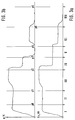
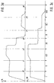
- Figure 3 are timing diagrams (not to scale) listed the expected course of the pressures in the 4 wheel brakes when performing the predrive test and error-free Represent operation of the brake system.
- Figure 4 shows a flowchart showing the implementation of the predrive test describes in a preferred embodiment.
- Figure 1 shows a preferred embodiment of a electrohydraulic brake system. It shows a master brake cylinder HBZ with storage container 10 to which one from Driver operated brake pedal is attached. Further is a hydraulic unit 14 is provided, which valve and pump arrangements to control the wheel brakes 16, 18, 20 and 22 contains. With the brake pedal 12 is a brake pedal switch 24 connected, which when the brake pedal is pressed closes, and a measuring device 26 for detecting the deflection of the brake pedal. The brake pedal switch can be used as simple normally open or be designed to improve Can be monitored as a double switch with an NC contact and a closer. A pedal travel simulator PWS is also provided, which is for the driver when the brake pedal is pressed a familiar pedal feeling with regard to counterforce and pedal deflection simulated.
- the two brake circuits HZ1 and HZ2 connected on the master brake cylinder HBZ.
- each MV_TVR and MV_TVL inserted, which closed by energization in the case of an electrically controlled brake system becomes.
- a pressure sensor 28 from the driver via the Brake pedal actuation applied pressure.
- the main brake cylinder is hydraulically separated from the isolating valves Pressure control system disconnected.
- Pressure control system In the pressure control system are for each wheel brake has a pressure modulator for brake pressure control contain.
- a pressure modulator consists of one Inlet valve (MV_UVR, MV_UVL, MV_UHR, MV_UHL), one outlet valve each (MV_DVR, MV_DVL, MV_DHR, MV_DHL) and one each Pressure sensor 30, 32, 34 and 36, which the pressure in the wheel brake leading management measures.
- MV_UVR, MV_UVL, MV_UHR, MV_UHL Inlet valve
- MV_DVR MV_DVL
- MV_DHR MV_DHR
- MV_DHL Pressure sensor 30, 32, 34 and 36
- relief valves are MV_EVA and MV_EHA for everyone Axis provided, the pressure reduction in the de-energized state allow from the wheel pressure modulators of an axle. You connect the pressure modulators of an axis with those to the reservoir 10 leading return lines. In the electrically controlled Operating status, these two valves are permanent energized, i.e. closed. There is also a temperature compensation valve MV_TKVL and MV_TKVR for everyone Front wheel pressure modulator provided. These valves are deenergized are closed and are released from the pressure modulator for pressure reduction of a front wheel opened by energization when certain conditions, especially a very long one Braking time. The temperature compensation valves connect the brake line to the wheel brake with the return line.
- the energy for brake pressure modulation comes from a single-piston high-pressure pump driven by an electric motor 42. This is at a high pressure accumulator 44 connected, which serves as an intermediate buffer and its pressure is detected by a pressure sensor 46.
- the pressure line of the Pump 42 leads to the inlet valves of the wheel brakes while the suction line of the pump 42 connected to the reservoir 10 is.
- the invention described below How-to, however, is not only related advantageously used with such a hydraulic circuit, but wherever in connection with electrical controlled brake system with electrically controllable Pressure supply the pressure in a memory element is detected and is used to control the brake system.
- the temperature compensation valves and the relief valves omitted in one embodiment.
- the brake system described in FIG. 1 operates in normal operation as follows.
- the driver steps on the brake pedal. He senses a path-dependent counterforce. This path dependency is defined by the characteristic of the pedal travel simulator educated.
- the brake pedal switch and / or the The isolating valves (MV_TVR and MV_TVL) and the relief valves (MV_EVA and MV_EHA) closed.
- the Master brake cylinder HBZ builds up a pressure that from the Pedal force results. From the signals of the brake light switch 24, the displacement sensor 26 and / or the pressure sensor 28 the driver's braking request, for example, as a target deceleration or calculated as the target braking force.
- the individual target wheel brake pressures are formed. Each these pressures depend on the driving condition and slip condition modified and via the wheel pressure modulators through valve energization adjusted. Be in a closed loop the current pressures on the wheel pressure sensors for each wheel brake used for the target-actual comparison. With different Target pressures in the left and right wheel one The equalization valves are closed in each axis Wheel brake the predetermined target pressure by controlling the intake and exhaust valves in the sense of regulating the actual brake pressure adjusted to the target brake pressure. To build up pressure on a wheel brake, the inlet valve is energized so far, that the desired target pressure in the wheel brake with the desired dynamics. A decrease in pressure is achieved accordingly by energizing the exhaust valve, taking brake fluid over to the reservoir the return line flows back.
- the relief valves come into effect in the event of a fault in the system. If during if the braking system fails, all fall Valves return to their de-energized state. The relief valves then open the pressure modulators to the return line, so that no brake pressure can be locked up. These valves also allow volume compensation in the idle state to the container in case of temperature fluctuations.
- the electrically operated valves and the pump 42 are controlled by at least one electronic control unit, which is outlined in Figure 2. It includes at least a microcomputer 102, an input circuit 104, an output circuit 106 and a connecting these elements Bus system 108 for mutual data exchange.
- Input circuit 104 is lines 50 and 54 of FIG Brake pedal switch 24 and pedal travel sensor 26 supplied. Further input lines 118 through 124 connect the input circuit 104 with the pressure sensors assigned to each wheel brake 30 to 36. An input line 140 is also provided, that of the measuring device 46 for detecting the storage pressure is fed to the input line 104. Further Input lines 126 through 128 connect the input circuit 104 with measuring devices 130 to 132 for detecting further Operating parameters of the brake system, the vehicle and / or its drive unit. Such operating sizes are, for example the wheel speeds, possibly that of the engine torque, axle loads, the Pressure in the brake line (sensor 28), etc. To the output circuit 106, several output lines are connected. The output lines are shown by way of example which the valves of the pressure modulators are operated. The pump 42 is controlled via a further output line 138. The control unit 100 controls the brake system depending on of the supplied signal quantities in the above Senses.
- FIG. 3 one is approximately reached during the self-test in the normal case Pressure curve shown in one embodiment.
- FIG. 3a shows the pressure curve for the right front wheel, Figure 3b for the left front wheel, Figure 3c the for the right rear wheel and figure 3d that for the left rear wheel.
- a first phase I supply the system with power Opening the inlet valves MV_Uxx with the dismantling valves closed MV_Dxx and isolation valves MV_Txx and balance valves MV_Bxx the pressure in the wheel brakes at the accumulator pressure level structured, i.e. via the pressure regulator depending on the deviation between target and actual pressure within the scope of a Ramp increased.
- the accumulator pressure level at the wheel brakes when ready System it is checked whether at everyone Wheel brake the expected pressure level P0 has been reached. Is if this is the case, in a second phase II the balance valves MV_Bxx opened. At the next point it will be checked whether the expected pressure level P1 approximates the Wheel brakes are present.
- This check is also error-free run through, is opened by opening the corresponding relief valve (if available) on the left front wheel and on Left rear wheel on the right with the exhaust valve closed Front wheel and on the right rear wheel (MV_DVL, MV_DHL) the Pressure in the left front brake and the left rear brake reduced to 0 while in the right front wheel brake and the pressure in the right rear brake a certain level (P3) is maintained.
- P3 the exhaust valve closed Front wheel and on the right rear wheel
- P3 the pressure in the left front brake and the left rear brake reduced to 0 while in the right front wheel brake and the pressure in the right rear brake a certain level (P3) is maintained.
- P3 the Close balance valves MV_Bxx.
- Phase V is after at a certain time, checking whether the predetermined pressure levels P4 were reached. This is also the case is in phase VI by opening the balance valves MV_Bxx brought about pressure equalization on the axes.
- step 100 Control valves MV_Uxx opened, the balance MV_Bxx and the Isolation valves MV_TXX and the relief valves MV_EXX closed. This will put the wheel brake pressure on the accumulator pressure guided.
- step 102 it is checked in step 104 whether the expected one Pressure value P0 was approximately reached in all wheel brakes. Is if this is not the case, an error condition must exist. Around isolating this is checked in step 106 whether the Pressure value P0 was not reached in more than one wheel brake.
- step 108 there is an error in the pressure supply (42, 44, 46 and associated circuits) close so that according to step 108 into a full emergency braking operation (hydraulic back-up) must be transferred in which all Valves are switched off.
- the driver then steers via the actuation of the brake pedal 12 hydraulic brake pressure into the wheel brakes on the front axle.
- step 110 3-wheel EMS operation initiated.
- this operation is the balance valve of the axis on which the error was detected closed. So only one wheel on this axis is braked. The other wheel is not braked.
- the possibly occurring Yaw moment is obtained from a state of the art known yaw moment build-up delay reduced. All wheel-specific functions such as anti-lock protection, traction control, Driving dynamics control, etc. and functions like an electronic brake force distribution, etc. are adjusted, switched off if necessary.
- the brake system in 3-wheel EMS operation will continue to be function monitors performed the correct functioning of the ensure reduced electronic operation.
- Step 104 has shown that the pressure value to be expected in All wheel brakes have been reached Balance valves MV_Bxx open. After the expiry of this Phase scheduled time T2 (step 114) is in step 116 checks whether the expected pressure P1 in all wheel brakes is available. If not, follow the steps 106 to 110 continued.
- step 116 The check in step 116 showed that the brake system is working properly, according to step 120 Pressure sensor calibration carried out and in the next step 122 the storage pressure pump for a period less than T3 switched on. This will remove the pressure on the wheel brakes further increased.
- T3 After a certain time T3 according to Step 124 then becomes step III at the end of this phase 126 checks whether the pressure P2 to be expected at all Wheel brakes is reached. If not, it will Checked according to step 128 whether it is not on both axes is reached. In this case it must be of a serious nature Errors are assumed, for example an error in the Storage pressure pump 42, a leak in the area of the pressure supply or significant gas content in the hydraulic fluid, so that according to step 130 a complete backup is initiated.
- the pressure value is not only on one axis reached, it is checked according to step 132 whether this is the Front axle is. In this case, for example, Error in the area of the media separator, a leak in the area the front axle pressure modulation, etc., so that on the front axle the hydraulic back-up is turned on while the correctly functioning rear axle in the electronic Regulation remains.
- the expected pressure was not reached, it will be correct working front axle brake in electronically controlled operation braked while the rear axle brakes were switched off become (de-energized intake valves).
- the electronically controlled part of the Brake system still monitored for errors.
- Step 126 has shown that the pressure to be expected at all Wheel brakes have been reached, according to step 138 Inlet valves MV_Uxx closed and the exhaust valves MV_Dxx controlled open. After a certain time T4 '(step 140) during which the exhaust valves are energized in step 142, the exhaust valves become MV_Dxx again closed. This makes a certain, predetermined one Relieved pressure. Instead of opening the exhaust valves completely is used in other embodiments with the pressure regulator the pressure is relieved. This improves noise. At the end of the time allotted for phase IV T4 (step 144) is checked in step 146 whether the after Pressure P3 expected at all wheel brakes during this phase was achieved.
- step 148 checks whether this is the case on all axes. In this Case is, for example, of constipation in the Return line to go out, so that a complete hydraulic Back-up is initiated according to step 150. Is only If an axis is affected, one of the Exhaust valves to go out, so that a step 132nd - 136 corresponding emergency braking operation is initiated.
- Step 146 showed that the pressure on all wheel brakes was reached, initiate phase V in step 154 the balance valves MV_Bxx closed and on front and A relief valve is opened on the rear axle. After that it is checked in step 146 whether the one to be expected in each case Wheel pressure is reached. This is for the wheel brakes where the relief valve is open, the value 0 (P4) the others the previous value (P3). Will the pressure value on a wheel is not reached, it is checked in step 158 whether both P4 and P3 were not reached. Is this the Case, e.g. a fault in the exhaust valve in question and a leak in the area of the wheel brake. In this According to step 160, the case becomes analogous to the procedure of Steps 148-152 proceeded.
- step 162 Is only on a wheel brake either P4 or P3 is not reached (step 162), then isolate this wheel brake according to step 164 in 3-wheel EMS operation. If P3 or P4 is not reached on two or more wheel brakes has been, according to step 166, corresponding to the Steps 148-152 proceeded.
- step 168 the relief valves are opened closed and the balance valves MV_Bxx opened.
- step 172 of the expected pressure P5 checked. Will this pressure not reached, takes place between the wheel brakes of an axle no proper pressure equalization takes place, i.e. the corresponding Balance valve does not open properly. It is not significant restriction of operation, so that according to Step 174 the driver is only warned by a warning lamp becomes.
- step 176 the isolation valves MV_Txx and Pressure relief valves on the rear axle open.
- step 180 the wheel brake pressures to the value P6, namely 0, checked.
- P6 the value of the wheel brake
- step 182 a check is made in step 182 to determine whether this is the case on more than one front brake. Is this the Case, is from a faulty closing of both isolation valves go out, so that according to 184 only a limited Operation of the vehicle, for example, as part of a Power limitation is possible. It's just a front brake concerned, it is checked in step 186 whether a rear axle brake is affected.
- step 190 If this is not the case, the front brake associated with this isolating valve and a 3-wheel EMS operation carried out according to step 190. Is a rear axle brake is affected, the step 188 Rear axle switched off. According to step 180, this is also the last phase of the test has been successfully completed the EMS operation is released in accordance with step 192.
- the test is stopped immediately and functional reliability is ensured through checks, that are carried out during operation.
- suitable modification e.g. by not opening of the isolation valves
- the test can also be carried out with the brake pedal depressed be performed.
- the test is preferably carried out in noise and time optimized so that the greatest possible for a driver Comfort and the fastest possible availability of the brake is achieved.
- the pressure build-up and the pressure reduction of the pressure regulator used, its setpoint is ramped in this sense until it is reached the pressure value intended for the test.
Landscapes
- Engineering & Computer Science (AREA)
- Transportation (AREA)
- Mechanical Engineering (AREA)
- Physics & Mathematics (AREA)
- Fluid Mechanics (AREA)
- Regulating Braking Force (AREA)
- Valves And Accessory Devices For Braking Systems (AREA)
Applications Claiming Priority (2)
| Application Number | Priority Date | Filing Date | Title |
|---|---|---|---|
| DE19807367A DE19807367A1 (de) | 1998-02-21 | 1998-02-21 | Verfahren und Vorrichtung zur Überprüfung einer Bremsanlage |
| DE19807367 | 1998-02-21 |
Publications (3)
| Publication Number | Publication Date |
|---|---|
| EP0937618A2 true EP0937618A2 (fr) | 1999-08-25 |
| EP0937618A3 EP0937618A3 (fr) | 2002-03-20 |
| EP0937618B1 EP0937618B1 (fr) | 2006-05-24 |
Family
ID=7858524
Family Applications (1)
| Application Number | Title | Priority Date | Filing Date |
|---|---|---|---|
| EP98118809A Expired - Lifetime EP0937618B1 (fr) | 1998-02-21 | 1998-10-05 | Procédé et dispositif pour contrôler la fonction d'un système de freinage |
Country Status (4)
| Country | Link |
|---|---|
| US (1) | US6206489B1 (fr) |
| EP (1) | EP0937618B1 (fr) |
| JP (1) | JP4587501B2 (fr) |
| DE (2) | DE19807367A1 (fr) |
Cited By (11)
| Publication number | Priority date | Publication date | Assignee | Title |
|---|---|---|---|---|
| EP1157911A1 (fr) * | 2000-05-19 | 2001-11-28 | Lucas Automotive Gmbh | Système de freinage véhicule avec deux circuits de freinage |
| EP1278669A1 (fr) * | 2000-05-05 | 2003-01-29 | Volvo Articulated Haulers AB | Agencement et procede d'activation d'une fonction de frein de secours dans un vehicule |
| WO2009016468A2 (fr) * | 2007-07-30 | 2009-02-05 | Toyota Jidosha Kabushiki Kaisha | Appareil de commande de pompe et système de commande de freinage |
| WO2009115145A1 (fr) * | 2008-03-19 | 2009-09-24 | Robert Bosch Gmbh | Procédé et dispositif destinés à contrôler et compenser les défaillances d'un système d'actionnement de frein de système de freinage électrique décentralisé |
| EP2495145A1 (fr) * | 2011-03-02 | 2012-09-05 | Jungheinrich Aktiengesellschaft | Véhicule, notamment chariot de manutention |
| WO2012100864A3 (fr) * | 2011-01-26 | 2013-03-21 | Robert Bosch Gmbh | Dispositif de commande pour un système de freinage de véhicule, système de freinage et procédé pour faire fonctionner un système de freinage de véhicule |
| EP1970274B1 (fr) * | 2000-08-04 | 2014-01-08 | Meggitt Aerospace Limited | Surveillance de l'état des freins |
| US8886378B2 (en) | 2012-01-25 | 2014-11-11 | Crown Equipment Corporation | System and method for monitoring state of function of a materials handling vehicle |
| WO2015169419A1 (fr) * | 2014-05-03 | 2015-11-12 | Audi Ag | Procédé de détection d'un dysfonctionnement de conduits de freinage |
| WO2017097797A1 (fr) * | 2015-12-10 | 2017-06-15 | Knorr-Bremse Systeme für Nutzfahrzeuge GmbH | Procédé de détection et de compensation d'une fuite dans un système de freinage |
| EP2298616A3 (fr) * | 2009-08-14 | 2018-01-24 | KNORR-BREMSE Systeme für Nutzfahrzeuge GmbH | Appareil de commande et procédé de test d'un dispositif de soupape d'un frein de stationnement électrique |
Families Citing this family (35)
| Publication number | Priority date | Publication date | Assignee | Title |
|---|---|---|---|---|
| US5941608A (en) | 1996-03-07 | 1999-08-24 | Kelsey-Hayes Company | Electronic brake management system with manual fail safe |
| JP2001260857A (ja) * | 2000-03-22 | 2001-09-26 | Aisin Seiki Co Ltd | 車両用制動制御装置 |
| JP2001260856A (ja) * | 2000-03-22 | 2001-09-26 | Aisin Seiki Co Ltd | 車両用制動制御装置 |
| DE10018178A1 (de) * | 2000-04-12 | 2001-10-25 | Bayerische Motoren Werke Ag | Elektrisch gesteuertes, insbesondere elektromechanisches Bremssystem für ein Kraftfahrzeug |
| DE10036287B4 (de) * | 2000-07-26 | 2009-07-30 | Robert Bosch Gmbh | Verfahren und Vorrichtung zur Steuerung von Radbremsen |
| GB2367869B (en) * | 2000-10-14 | 2004-10-06 | Trw Ltd | Rear-axle demand for use with front push-through in electrohydraulic (EHB) braking systems |
| DE10053334B4 (de) | 2000-10-27 | 2018-08-02 | Robert Bosch Gmbh | Verfahren und Vorrichtung zur Steuerung eines Stellelements in einem Fahrzeug |
| US6871917B2 (en) * | 2000-11-10 | 2005-03-29 | Continental Teves Ag & Co. Ohg | Device for controlling electromagnetically operated valves |
| JP2004537463A (ja) * | 2001-08-11 | 2004-12-16 | コンティネンタル・テーベス・アクチエンゲゼルシヤフト・ウント・コンパニー・オッフェネ・ハンデルスゲゼルシヤフト | 液圧式車両ブレーキの電子制御可能な弁の電流調整器を検査する方法 |
| US6860569B1 (en) | 2002-05-23 | 2005-03-01 | Kelsey-Hayes Company | Electro-hydraulic brake system with four wheel push through |
| DE502004008243D1 (de) * | 2003-12-08 | 2008-11-20 | Continental Teves Ag & Co Ohg | Verfahren zur kalibrierung von analog regelnden elektrisch ansteuerbaren hydraulischen ventilen |
| DE102004027508A1 (de) * | 2004-06-04 | 2005-12-22 | Robert Bosch Gmbh | Hydraulische Bremsanlage und Verfahren zur Beeinflussung einer hydraulischen Bremsanlage |
| JP2006123688A (ja) * | 2004-10-28 | 2006-05-18 | Advics:Kk | アクチュエータのイニシャルチェック機能を備えたブレーキ装置 |
| JP4215074B2 (ja) * | 2006-06-28 | 2009-01-28 | トヨタ自動車株式会社 | ブレーキ制御装置及びブレーキ制御方法 |
| US8311699B2 (en) * | 2008-02-06 | 2012-11-13 | General Electric Company | Automatic brake verification system |
| CN102470834B (zh) * | 2010-04-29 | 2014-11-05 | 丰田自动车株式会社 | 车辆用液压制动系统 |
| DE102010041642A1 (de) * | 2010-09-29 | 2012-03-29 | Robert Bosch Gmbh | Bremssystem für ein Fahrzeug |
| DE102012020010A1 (de) * | 2012-10-12 | 2014-04-17 | Volkswagen Aktiengesellschaft | Verfahren zur Steuerung eines Bremssystems |
| JP5969933B2 (ja) * | 2013-02-12 | 2016-08-17 | 日立オートモティブシステムズ株式会社 | ブレーキ装置 |
| DE102013019512A1 (de) | 2013-11-21 | 2015-05-21 | Wabco Gmbh | Überprüfung der Verbauungsposition von Achsmodulatoren anhand von Störungen inGeschwindigkeitssignalen |
| WO2015116626A1 (fr) | 2014-01-28 | 2015-08-06 | General Electric Company | Système et procédé de vérification d'un système de freinage |
| US10124783B2 (en) | 2016-11-02 | 2018-11-13 | Veoneer Nissin Brake Systems Japan Co. Ltd. | Brake circuit leak detection and isolation |
| JP7133323B2 (ja) * | 2017-03-08 | 2022-09-08 | ハーレー-ダビッドソン・モーター・カンパニー・グループ・エルエルシー | 固着したバルブを検出するシステム及び方法 |
| JP7021921B2 (ja) * | 2017-12-04 | 2022-02-17 | 日立Astemo株式会社 | ブレーキシステム |
| US11014546B2 (en) | 2018-03-29 | 2021-05-25 | Veoneer-Nissin Brake Systems Japan Co., Ltd. | Brake system and method for responding to external boost requests during predetermined loss or degraded boost assist conditions |
| US10766474B2 (en) | 2018-03-30 | 2020-09-08 | Veoneer-Nissin Brake Systems Japan Co., Ltd. | Validating operation of a secondary braking system of a vehicle |
| US11383689B2 (en) | 2018-05-23 | 2022-07-12 | Haldex Brake Products Corporation | Brake monitoring system with temperature monitoring |
| DE102018212850A1 (de) * | 2018-08-01 | 2020-02-06 | Robert Bosch Gmbh | Verfahren zur Prüfung der Funktionsfähigkeit einer hydraulischen Fahrzeugbremsanlage |
| CN109334660A (zh) * | 2018-11-30 | 2019-02-15 | 安徽江淮汽车集团股份有限公司 | 一种自动紧急制动系统及轻量化评估方法 |
| DE102019207284A1 (de) * | 2019-05-18 | 2020-11-19 | Robert Bosch Gmbh | Verfahren und Vorrichtung zum Betreiben eines Bremssystems eines Kraftfahrzeugs, Bremssystem und Kraftfahrzeug |
| CN110763485A (zh) * | 2019-11-05 | 2020-02-07 | 中国汽车工程研究院股份有限公司 | 一种汽车抗热衰退制动系统性能测试方法及系统 |
| US11767005B2 (en) * | 2020-08-21 | 2023-09-26 | GM Global Technology Operations LLC | Test sequence for brake system |
| US12115960B2 (en) * | 2021-12-15 | 2024-10-15 | ZF Active Safety US Inc. | Apparatus and method for a hydraulic brake system including manual push-through |
| CN114486290A (zh) * | 2022-02-15 | 2022-05-13 | 宜宾凯翼汽车有限公司 | 用于汽车制动系统的可靠性试验装置 |
| WO2024005106A1 (fr) * | 2022-06-30 | 2024-01-04 | 日立建機株式会社 | Véhicule de chantier |
Citations (6)
| Publication number | Priority date | Publication date | Assignee | Title |
|---|---|---|---|---|
| EP0157309A2 (fr) * | 1984-04-02 | 1985-10-09 | Robert Bosch Gmbh | Procédé de surveillance pour un système de freinage |
| DE3418042A1 (de) * | 1984-05-15 | 1985-11-21 | Alfred Teves Gmbh, 6000 Frankfurt | Vorrichtung zur ueberwachung des hilfsenergie-druckes einer schlupfgeregelten bremsanlage |
| DE3630342A1 (de) * | 1986-09-05 | 1988-03-17 | Teves Gmbh Alfred | Blockiergeschuetzte hydraulische bremsanlage fuer kraftfahrzeuge |
| EP0357922A2 (fr) * | 1988-09-03 | 1990-03-14 | Daimler-Benz Aktiengesellschaft | Procédé de fonctionnement d'une installation électrique de freinage à fluide et dispositif de commande pour mettre en oeuvre ce procédé |
| JPH04243655A (ja) * | 1991-01-23 | 1992-08-31 | Toyota Motor Corp | 液圧発生装置の異常検出方法 |
| WO1995004674A1 (fr) * | 1993-08-11 | 1995-02-16 | Itt Automotive Europe Gmbh | Circuit de regulation de systemes de freinage a antiblocage automatique et/ou a systeme anti-patinage a l'acceleration |
Family Cites Families (10)
| Publication number | Priority date | Publication date | Assignee | Title |
|---|---|---|---|---|
| DE2614016A1 (de) * | 1976-04-01 | 1977-10-06 | Teldix Gmbh | Antiblockierregelsystem |
| DE3137200A1 (de) * | 1981-09-18 | 1983-03-31 | Robert Bosch Gmbh, 7000 Stuttgart | Zweikreis-bremseinrichtung |
| JPH02155867A (ja) * | 1988-12-07 | 1990-06-14 | Nissan Motor Co Ltd | 車両のブレーキ液圧制御装置 |
| GB8905311D0 (en) * | 1989-03-08 | 1989-04-19 | Lucas Ind Plc | Electronic braking system |
| JPH04243658A (ja) * | 1991-01-23 | 1992-08-31 | Toyota Motor Corp | 電気制御式ブレーキ装置のフェール検出方法 |
| JP3253674B2 (ja) * | 1992-05-08 | 2002-02-04 | マツダ株式会社 | 車両の自動制動装置 |
| JP3761095B2 (ja) * | 1994-12-07 | 2006-03-29 | 日産自動車株式会社 | アンチスキッド制御装置 |
| JP3401989B2 (ja) * | 1995-05-12 | 2003-04-28 | 日産自動車株式会社 | アンチスキッド制御装置 |
| JPH09240461A (ja) * | 1996-03-08 | 1997-09-16 | Suzuki Motor Corp | Abs診断装置 |
| JP3277899B2 (ja) * | 1997-10-13 | 2002-04-22 | トヨタ自動車株式会社 | ブレーキ液圧制御装置 |
-
1998
- 1998-02-21 DE DE19807367A patent/DE19807367A1/de not_active Ceased
- 1998-10-05 EP EP98118809A patent/EP0937618B1/fr not_active Expired - Lifetime
- 1998-10-05 DE DE59813553T patent/DE59813553D1/de not_active Expired - Lifetime
-
1999
- 1999-02-19 US US09/252,759 patent/US6206489B1/en not_active Expired - Lifetime
- 1999-02-19 JP JP04091099A patent/JP4587501B2/ja not_active Expired - Fee Related
Patent Citations (6)
| Publication number | Priority date | Publication date | Assignee | Title |
|---|---|---|---|---|
| EP0157309A2 (fr) * | 1984-04-02 | 1985-10-09 | Robert Bosch Gmbh | Procédé de surveillance pour un système de freinage |
| DE3418042A1 (de) * | 1984-05-15 | 1985-11-21 | Alfred Teves Gmbh, 6000 Frankfurt | Vorrichtung zur ueberwachung des hilfsenergie-druckes einer schlupfgeregelten bremsanlage |
| DE3630342A1 (de) * | 1986-09-05 | 1988-03-17 | Teves Gmbh Alfred | Blockiergeschuetzte hydraulische bremsanlage fuer kraftfahrzeuge |
| EP0357922A2 (fr) * | 1988-09-03 | 1990-03-14 | Daimler-Benz Aktiengesellschaft | Procédé de fonctionnement d'une installation électrique de freinage à fluide et dispositif de commande pour mettre en oeuvre ce procédé |
| JPH04243655A (ja) * | 1991-01-23 | 1992-08-31 | Toyota Motor Corp | 液圧発生装置の異常検出方法 |
| WO1995004674A1 (fr) * | 1993-08-11 | 1995-02-16 | Itt Automotive Europe Gmbh | Circuit de regulation de systemes de freinage a antiblocage automatique et/ou a systeme anti-patinage a l'acceleration |
Non-Patent Citations (2)
| Title |
|---|
| JONNER W-D ET AL: "ELECTROHYDRAULIC BRAKE SYSTEM - THE FIRS APPROACH TO BRAKE-BY-WIRE TECHNOLOGY" CURRENT AND FUTURE DEVELOPMENTS IN ABS/TCS AND BRAKE TECHNOLOGY, XX, XX, 1. Februar 1996 (1996-02-01), Seiten 105-112, XP000199045 * |
| PATENT ABSTRACTS OF JAPAN vol. 017, no. 012 (M-1351), 11. Januar 1993 (1993-01-11) & JP 04 243655 A (TOYOTA MOTOR CORP), 31. August 1992 (1992-08-31) * |
Cited By (20)
| Publication number | Priority date | Publication date | Assignee | Title |
|---|---|---|---|---|
| EP1278669A1 (fr) * | 2000-05-05 | 2003-01-29 | Volvo Articulated Haulers AB | Agencement et procede d'activation d'une fonction de frein de secours dans un vehicule |
| US7347506B2 (en) | 2000-05-05 | 2008-03-25 | Volvo Construction Equipment Ab | Arrangement and method for activating an emergency brake function within a vehicle |
| EP1157911A1 (fr) * | 2000-05-19 | 2001-11-28 | Lucas Automotive Gmbh | Système de freinage véhicule avec deux circuits de freinage |
| EP1970274B1 (fr) * | 2000-08-04 | 2014-01-08 | Meggitt Aerospace Limited | Surveillance de l'état des freins |
| WO2009016468A2 (fr) * | 2007-07-30 | 2009-02-05 | Toyota Jidosha Kabushiki Kaisha | Appareil de commande de pompe et système de commande de freinage |
| WO2009016468A3 (fr) * | 2007-07-30 | 2009-03-26 | Toyota Motor Co Ltd | Appareil de commande de pompe et système de commande de freinage |
| US8708428B2 (en) | 2007-07-30 | 2014-04-29 | Toyota Jidosha Kabushiki Kaisha | Pump control apparatus and brake control system |
| CN101772441B (zh) * | 2007-07-30 | 2012-11-28 | 丰田自动车株式会社 | 泵控制设备和制动控制系统 |
| WO2009115145A1 (fr) * | 2008-03-19 | 2009-09-24 | Robert Bosch Gmbh | Procédé et dispositif destinés à contrôler et compenser les défaillances d'un système d'actionnement de frein de système de freinage électrique décentralisé |
| EP2298616A3 (fr) * | 2009-08-14 | 2018-01-24 | KNORR-BREMSE Systeme für Nutzfahrzeuge GmbH | Appareil de commande et procédé de test d'un dispositif de soupape d'un frein de stationnement électrique |
| WO2012100864A3 (fr) * | 2011-01-26 | 2013-03-21 | Robert Bosch Gmbh | Dispositif de commande pour un système de freinage de véhicule, système de freinage et procédé pour faire fonctionner un système de freinage de véhicule |
| US9248812B2 (en) | 2011-01-26 | 2016-02-02 | Robert Bosch Gmbh | Control device for a braking system of a vehicle, braking system, and method for operating a braking system for a vehicle |
| EP2495145A1 (fr) * | 2011-03-02 | 2012-09-05 | Jungheinrich Aktiengesellschaft | Véhicule, notamment chariot de manutention |
| US8886378B2 (en) | 2012-01-25 | 2014-11-11 | Crown Equipment Corporation | System and method for monitoring state of function of a materials handling vehicle |
| WO2015169419A1 (fr) * | 2014-05-03 | 2015-11-12 | Audi Ag | Procédé de détection d'un dysfonctionnement de conduits de freinage |
| CN106232442A (zh) * | 2014-05-03 | 2016-12-14 | 奥迪股份公司 | 用于识别制动管路的错误装配的方法 |
| US10077038B2 (en) | 2014-05-03 | 2018-09-18 | Audi Ag | Method for detecting an incorrect installation of brake lines |
| CN106232442B (zh) * | 2014-05-03 | 2019-04-05 | 奥迪股份公司 | 用于识别制动管路的错误装配的方法 |
| WO2017097797A1 (fr) * | 2015-12-10 | 2017-06-15 | Knorr-Bremse Systeme für Nutzfahrzeuge GmbH | Procédé de détection et de compensation d'une fuite dans un système de freinage |
| CN108602505A (zh) * | 2015-12-10 | 2018-09-28 | 克诺尔商用车制动系统有限公司 | 用于探测和补偿制动装置中的泄漏的方法 |
Also Published As
| Publication number | Publication date |
|---|---|
| EP0937618B1 (fr) | 2006-05-24 |
| DE59813553D1 (de) | 2006-06-29 |
| DE19807367A1 (de) | 1999-08-26 |
| JP4587501B2 (ja) | 2010-11-24 |
| EP0937618A3 (fr) | 2002-03-20 |
| JPH11348769A (ja) | 1999-12-21 |
| US6206489B1 (en) | 2001-03-27 |
Similar Documents
| Publication | Publication Date | Title |
|---|---|---|
| EP0937618B1 (fr) | Procédé et dispositif pour contrôler la fonction d'un système de freinage | |
| EP0937620B1 (fr) | Procédé et dispositif de contrôle d' un système de freinage | |
| EP0937617B1 (fr) | Procédé et dispositif pour contrôler un système de freinage | |
| EP0937621B1 (fr) | Procédé et dispositif de contrôle d' un système de freinage | |
| EP2229302B1 (fr) | Installation de freinage pour un véhicule, et système de pédale de frein pour une telle installation de freinage | |
| DE10036287B4 (de) | Verfahren und Vorrichtung zur Steuerung von Radbremsen | |
| DE19616538B4 (de) | Elektrohydraulische Bremsanlage | |
| DE19732884C2 (de) | Vorrichtung zur Steuerung des Bremsfluiddrucks in einem Fahrzeugbremssystem | |
| DE19603863B4 (de) | Verfahren und Vorrichtungen zur Überprüfung der Bremsanlage eines Fahrzeugs | |
| DE102017121761B4 (de) | Elektropneumatisches Bremssystem mit Testmodus für den pneumatischen Backup-Bremskreis sowie Fahrzeug mit einem solchen Bremssystem | |
| EP1339582A1 (fr) | Procedes de commande d'un systeme de freinage electro-hydraulique | |
| WO1998035864A1 (fr) | Procede et dispositif permettant de commander la repartition de la force de freinage d'un vehicule automobile | |
| DE19729097B4 (de) | Verfahren und Vorrichtung zur Steuerung einer Bremsanlage | |
| DE19811265B4 (de) | Verfahren und Vorrichtung zur Steuerung einer Bremsanlage | |
| EP1055576B1 (fr) | Système de freinage électro-hydraulique et son procédé de commande | |
| DE19706850A1 (de) | Verfahren und Vorrichtung zur Steuerung einer Bremsanlage eines Fahrzeugs | |
| DE19603867A1 (de) | Verfahren und Vorrichtung zur Überprüfung der Bremsanlage eines Fahrzeugs | |
| DE102019204904B3 (de) | Bremskrafterzeuger und Betriebsverfahren | |
| DE3828931A1 (de) | Verfahren zur ueberwachung der funktion einer bremsanlage | |
| DE69833404T2 (de) | Manuelle Hinterbremssteuerung für eine elektro-hydraulische Bremsanlage | |
| EP1515882B1 (fr) | Systeme de freinage electropneumatique de remorque et son procede de fonctionnement | |
| DE102021118006A1 (de) | Verfahren zur Funktionsüberprüfung eines druckmittelbetriebenen elektronischen Bremssystems eines Fahrzeugs | |
| WO2024012900A1 (fr) | Procédé de détermination d'une pression de freinage et dispositif de freinage actionné par un fluide sous pression | |
| DE10215867A1 (de) | Elektrohydraulisches Bremssystem mit druckgasunterstützter Rückfallebene | |
| WO2021078997A1 (fr) | Procédé pour faire fonctionner un système de freinage à frein de stationnement intégré et système de freinage |
Legal Events
| Date | Code | Title | Description |
|---|---|---|---|
| PUAI | Public reference made under article 153(3) epc to a published international application that has entered the european phase |
Free format text: ORIGINAL CODE: 0009012 |
|
| AK | Designated contracting states |
Kind code of ref document: A2 Designated state(s): AT BE CH CY DE DK ES FI FR GB GR IE IT LI LU MC NL PT SE |
|
| AX | Request for extension of the european patent |
Free format text: AL;LT;LV;MK;RO;SI |
|
| PUAL | Search report despatched |
Free format text: ORIGINAL CODE: 0009013 |
|
| AK | Designated contracting states |
Kind code of ref document: A3 Designated state(s): AT BE CH CY DE DK ES FI FR GB GR IE IT LI LU MC NL PT SE |
|
| AX | Request for extension of the european patent |
Free format text: AL;LT;LV;MK;RO;SI |
|
| RIC1 | Information provided on ipc code assigned before grant |
Free format text: 7B 60T 8/88 A, 7B 60T 13/66 B, 7G 05B 9/02 B, 7B 60T 13/74 B, 7B 60T 7/04 B, 7B 60T 8/40 B, 7B 60T 17/22 B |
|
| 17P | Request for examination filed |
Effective date: 20020920 |
|
| AKX | Designation fees paid |
Free format text: DE FR GB |
|
| GRAP | Despatch of communication of intention to grant a patent |
Free format text: ORIGINAL CODE: EPIDOSNIGR1 |
|
| GRAS | Grant fee paid |
Free format text: ORIGINAL CODE: EPIDOSNIGR3 |
|
| GRAA | (expected) grant |
Free format text: ORIGINAL CODE: 0009210 |
|
| AK | Designated contracting states |
Kind code of ref document: B1 Designated state(s): DE FR GB |
|
| REG | Reference to a national code |
Ref country code: GB Ref legal event code: FG4D Free format text: NOT ENGLISH |
|
| REF | Corresponds to: |
Ref document number: 59813553 Country of ref document: DE Date of ref document: 20060629 Kind code of ref document: P |
|
| GBT | Gb: translation of ep patent filed (gb section 77(6)(a)/1977) |
Effective date: 20060918 |
|
| ET | Fr: translation filed | ||
| PLBE | No opposition filed within time limit |
Free format text: ORIGINAL CODE: 0009261 |
|
| STAA | Information on the status of an ep patent application or granted ep patent |
Free format text: STATUS: NO OPPOSITION FILED WITHIN TIME LIMIT |
|
| 26N | No opposition filed |
Effective date: 20070227 |
|
| PGFP | Annual fee paid to national office [announced via postgrant information from national office to epo] |
Ref country code: GB Payment date: 20101021 Year of fee payment: 13 |
|
| PGFP | Annual fee paid to national office [announced via postgrant information from national office to epo] |
Ref country code: FR Payment date: 20111103 Year of fee payment: 14 |
|
| GBPC | Gb: european patent ceased through non-payment of renewal fee |
Effective date: 20121005 |
|
| REG | Reference to a national code |
Ref country code: FR Ref legal event code: ST Effective date: 20130628 |
|
| PG25 | Lapsed in a contracting state [announced via postgrant information from national office to epo] |
Ref country code: GB Free format text: LAPSE BECAUSE OF NON-PAYMENT OF DUE FEES Effective date: 20121005 |
|
| PG25 | Lapsed in a contracting state [announced via postgrant information from national office to epo] |
Ref country code: FR Free format text: LAPSE BECAUSE OF NON-PAYMENT OF DUE FEES Effective date: 20121031 |
|
| REG | Reference to a national code |
Ref country code: DE Ref legal event code: R084 Ref document number: 59813553 Country of ref document: DE Effective date: 20130723 |
|
| PGFP | Annual fee paid to national office [announced via postgrant information from national office to epo] |
Ref country code: DE Payment date: 20151215 Year of fee payment: 18 |
|
| REG | Reference to a national code |
Ref country code: DE Ref legal event code: R119 Ref document number: 59813553 Country of ref document: DE |
|
| PG25 | Lapsed in a contracting state [announced via postgrant information from national office to epo] |
Ref country code: DE Free format text: LAPSE BECAUSE OF NON-PAYMENT OF DUE FEES Effective date: 20170503 |