EP0937620B1 - Procédé et dispositif de contrôle d' un système de freinage - Google Patents
Procédé et dispositif de contrôle d' un système de freinage Download PDFInfo
- Publication number
- EP0937620B1 EP0937620B1 EP98118433A EP98118433A EP0937620B1 EP 0937620 B1 EP0937620 B1 EP 0937620B1 EP 98118433 A EP98118433 A EP 98118433A EP 98118433 A EP98118433 A EP 98118433A EP 0937620 B1 EP0937620 B1 EP 0937620B1
- Authority
- EP
- European Patent Office
- Prior art keywords
- wheel
- pressure
- fault
- axle
- brake
- Prior art date
- Legal status (The legal status is an assumption and is not a legal conclusion. Google has not performed a legal analysis and makes no representation as to the accuracy of the status listed.)
- Expired - Lifetime
Links
Images
Classifications
-
- B—PERFORMING OPERATIONS; TRANSPORTING
- B60—VEHICLES IN GENERAL
- B60T—VEHICLE BRAKE CONTROL SYSTEMS OR PARTS THEREOF; BRAKE CONTROL SYSTEMS OR PARTS THEREOF, IN GENERAL; ARRANGEMENT OF BRAKING ELEMENTS ON VEHICLES IN GENERAL; PORTABLE DEVICES FOR PREVENTING UNWANTED MOVEMENT OF VEHICLES; VEHICLE MODIFICATIONS TO FACILITATE COOLING OF BRAKES
- B60T17/00—Component parts, details, or accessories of power brake systems not covered by groups B60T8/00, B60T13/00 or B60T15/00, or presenting other characteristic features
- B60T17/18—Safety devices; Monitoring
- B60T17/22—Devices for monitoring or checking brake systems; Signal devices
- B60T17/221—Procedure or apparatus for checking or keeping in a correct functioning condition of brake systems
-
- B—PERFORMING OPERATIONS; TRANSPORTING
- B60—VEHICLES IN GENERAL
- B60T—VEHICLE BRAKE CONTROL SYSTEMS OR PARTS THEREOF; BRAKE CONTROL SYSTEMS OR PARTS THEREOF, IN GENERAL; ARRANGEMENT OF BRAKING ELEMENTS ON VEHICLES IN GENERAL; PORTABLE DEVICES FOR PREVENTING UNWANTED MOVEMENT OF VEHICLES; VEHICLE MODIFICATIONS TO FACILITATE COOLING OF BRAKES
- B60T13/00—Transmitting braking action from initiating means to ultimate brake actuator with power assistance or drive; Brake systems incorporating such transmitting means, e.g. air-pressure brake systems
- B60T13/10—Transmitting braking action from initiating means to ultimate brake actuator with power assistance or drive; Brake systems incorporating such transmitting means, e.g. air-pressure brake systems with fluid assistance, drive, or release
- B60T13/66—Electrical control in fluid-pressure brake systems
- B60T13/68—Electrical control in fluid-pressure brake systems by electrically-controlled valves
- B60T13/686—Electrical control in fluid-pressure brake systems by electrically-controlled valves in hydraulic systems or parts thereof
-
- B—PERFORMING OPERATIONS; TRANSPORTING
- B60—VEHICLES IN GENERAL
- B60T—VEHICLE BRAKE CONTROL SYSTEMS OR PARTS THEREOF; BRAKE CONTROL SYSTEMS OR PARTS THEREOF, IN GENERAL; ARRANGEMENT OF BRAKING ELEMENTS ON VEHICLES IN GENERAL; PORTABLE DEVICES FOR PREVENTING UNWANTED MOVEMENT OF VEHICLES; VEHICLE MODIFICATIONS TO FACILITATE COOLING OF BRAKES
- B60T7/00—Brake-action initiating means
- B60T7/02—Brake-action initiating means for personal initiation
- B60T7/04—Brake-action initiating means for personal initiation foot actuated
- B60T7/042—Brake-action initiating means for personal initiation foot actuated by electrical means, e.g. using travel or force sensors
-
- B—PERFORMING OPERATIONS; TRANSPORTING
- B60—VEHICLES IN GENERAL
- B60T—VEHICLE BRAKE CONTROL SYSTEMS OR PARTS THEREOF; BRAKE CONTROL SYSTEMS OR PARTS THEREOF, IN GENERAL; ARRANGEMENT OF BRAKING ELEMENTS ON VEHICLES IN GENERAL; PORTABLE DEVICES FOR PREVENTING UNWANTED MOVEMENT OF VEHICLES; VEHICLE MODIFICATIONS TO FACILITATE COOLING OF BRAKES
- B60T8/00—Arrangements for adjusting wheel-braking force to meet varying vehicular or ground-surface conditions, e.g. limiting or varying distribution of braking force
- B60T8/32—Arrangements for adjusting wheel-braking force to meet varying vehicular or ground-surface conditions, e.g. limiting or varying distribution of braking force responsive to a speed condition, e.g. acceleration or deceleration
- B60T8/34—Arrangements for adjusting wheel-braking force to meet varying vehicular or ground-surface conditions, e.g. limiting or varying distribution of braking force responsive to a speed condition, e.g. acceleration or deceleration having a fluid pressure regulator responsive to a speed condition
- B60T8/40—Arrangements for adjusting wheel-braking force to meet varying vehicular or ground-surface conditions, e.g. limiting or varying distribution of braking force responsive to a speed condition, e.g. acceleration or deceleration having a fluid pressure regulator responsive to a speed condition comprising an additional fluid circuit including fluid pressurising means for modifying the pressure of the braking fluid, e.g. including wheel driven pumps for detecting a speed condition, or pumps which are controlled by means independent of the braking system
- B60T8/4072—Systems in which a driver input signal is used as a control signal for the additional fluid circuit which is normally used for braking
- B60T8/4081—Systems with stroke simulating devices for driver input
- B60T8/4086—Systems with stroke simulating devices for driver input the stroke simulating device being connected to, or integrated in the driver input device
-
- B—PERFORMING OPERATIONS; TRANSPORTING
- B60—VEHICLES IN GENERAL
- B60T—VEHICLE BRAKE CONTROL SYSTEMS OR PARTS THEREOF; BRAKE CONTROL SYSTEMS OR PARTS THEREOF, IN GENERAL; ARRANGEMENT OF BRAKING ELEMENTS ON VEHICLES IN GENERAL; PORTABLE DEVICES FOR PREVENTING UNWANTED MOVEMENT OF VEHICLES; VEHICLE MODIFICATIONS TO FACILITATE COOLING OF BRAKES
- B60T8/00—Arrangements for adjusting wheel-braking force to meet varying vehicular or ground-surface conditions, e.g. limiting or varying distribution of braking force
- B60T8/32—Arrangements for adjusting wheel-braking force to meet varying vehicular or ground-surface conditions, e.g. limiting or varying distribution of braking force responsive to a speed condition, e.g. acceleration or deceleration
- B60T8/88—Arrangements for adjusting wheel-braking force to meet varying vehicular or ground-surface conditions, e.g. limiting or varying distribution of braking force responsive to a speed condition, e.g. acceleration or deceleration with failure responsive means, i.e. means for detecting and indicating faulty operation of the speed responsive control means
- B60T8/885—Arrangements for adjusting wheel-braking force to meet varying vehicular or ground-surface conditions, e.g. limiting or varying distribution of braking force responsive to a speed condition, e.g. acceleration or deceleration with failure responsive means, i.e. means for detecting and indicating faulty operation of the speed responsive control means using electrical circuitry
-
- B—PERFORMING OPERATIONS; TRANSPORTING
- B60—VEHICLES IN GENERAL
- B60T—VEHICLE BRAKE CONTROL SYSTEMS OR PARTS THEREOF; BRAKE CONTROL SYSTEMS OR PARTS THEREOF, IN GENERAL; ARRANGEMENT OF BRAKING ELEMENTS ON VEHICLES IN GENERAL; PORTABLE DEVICES FOR PREVENTING UNWANTED MOVEMENT OF VEHICLES; VEHICLE MODIFICATIONS TO FACILITATE COOLING OF BRAKES
- B60T8/00—Arrangements for adjusting wheel-braking force to meet varying vehicular or ground-surface conditions, e.g. limiting or varying distribution of braking force
- B60T8/32—Arrangements for adjusting wheel-braking force to meet varying vehicular or ground-surface conditions, e.g. limiting or varying distribution of braking force responsive to a speed condition, e.g. acceleration or deceleration
- B60T8/88—Arrangements for adjusting wheel-braking force to meet varying vehicular or ground-surface conditions, e.g. limiting or varying distribution of braking force responsive to a speed condition, e.g. acceleration or deceleration with failure responsive means, i.e. means for detecting and indicating faulty operation of the speed responsive control means
- B60T8/92—Arrangements for adjusting wheel-braking force to meet varying vehicular or ground-surface conditions, e.g. limiting or varying distribution of braking force responsive to a speed condition, e.g. acceleration or deceleration with failure responsive means, i.e. means for detecting and indicating faulty operation of the speed responsive control means automatically taking corrective action
- B60T8/96—Arrangements for adjusting wheel-braking force to meet varying vehicular or ground-surface conditions, e.g. limiting or varying distribution of braking force responsive to a speed condition, e.g. acceleration or deceleration with failure responsive means, i.e. means for detecting and indicating faulty operation of the speed responsive control means automatically taking corrective action on speed responsive control means
-
- B—PERFORMING OPERATIONS; TRANSPORTING
- B60—VEHICLES IN GENERAL
- B60T—VEHICLE BRAKE CONTROL SYSTEMS OR PARTS THEREOF; BRAKE CONTROL SYSTEMS OR PARTS THEREOF, IN GENERAL; ARRANGEMENT OF BRAKING ELEMENTS ON VEHICLES IN GENERAL; PORTABLE DEVICES FOR PREVENTING UNWANTED MOVEMENT OF VEHICLES; VEHICLE MODIFICATIONS TO FACILITATE COOLING OF BRAKES
- B60T2270/00—Further aspects of brake control systems not otherwise provided for
- B60T2270/40—Failsafe aspects of brake control systems
- B60T2270/406—Test-mode; Self-diagnosis
Definitions
- the invention relates to a method and a device for controlling a brake system according to the preambles of the independent claims.
- Such a method or device is known, for example, from SAE Paper 960991.
- an electro-hydraulic brake system is described in which a braking request of the driver is derived from the brake pedal operation by the driver. If desired, this braking request is converted into desired brake pressures for the individual wheel brakes taking into account further operating variables.
- the desired brake pressures are adjusted for each wheel by pressure control loops on the basis of the predetermined target pressure and the actual brake pressure measured in the area of the wheel brake. Since the brake pressure in the wheel brakes in such an electro-hydraulic brake system is adjusted and modulated electrically via valve arrangements depending on the driver's braking request, emergency braking operations are to be ensured in the event of a fault, which ensure a sufficient braking effect even in the event of a fault.
- a shutdown of electrical system and switching to a hydraulic brake or electric operation only three wheel brakes proposed. Thus, most errors can be satisfactorily mastered, however, in some cases, however, switching to the hydraulic operation.
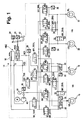
- FIG. 1 shows a preferred embodiment of an electro-hydraulic brake system
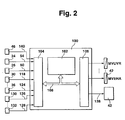
- FIG. 2 shows the control unit controlling the electro-hydraulic brake system
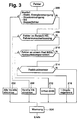
- FIG. 3 shows a flow chart illustrating a preferred implementation of the emergency operations of an electro-hydraulic brake system as a program of a microcomputer.
- Figure 1 shows a preferred embodiment of an electro-hydraulic brake system. It shows a master cylinder HBZ with reservoir 10, to which a driver operable brake pedal is mounted. Furthermore, a hydraulic unit 14 is provided which contains valve and pump arrangements for controlling the wheel brakes 16, 18, 20 and 22. To the brake pedal 12, a brake pedal switch 24 is connected, which closes upon actuation of the brake pedal, and a measuring device 26 for detecting the deflection of the brake pedal.
- the brake pedal switch can be designed as a simple closer, or to improve the monitorability as a double switch with a normally closed contact and a closer. Likewise, the measuring device 26 can be designed to be redundant for detecting the deflection of the pedal.
- a pedal travel PWS is provided, which simulates a counterforce for the driver upon actuation of the brake pedal.
- the two brake circuits HZ1 and HZ2 are connected to the master brake cylinder HBZ.
- a separating valve MV_TVR and MV_TVL are inserted, which is closed by energization in electrically controlled brake system.
- a pressure sensor 28 measures the pressure applied by the driver via the brake pedal actuation. With closed isolation valves, the master cylinder is hydraulically disconnected from the pressure control system.
- the pressure control system includes a pressure modulator for brake pressure control for each wheel brake.
- a pressure modulator consists of one inlet valve (MV_UVR, MV_UVL, MV_UHR, MV_UHL), one outlet valve (MV_DVR, MV_DVL, MV_DHR, MV_DHL) and one pressure sensor 30, 32, 34 and 36 each, which controls the pressure in the wheel brake Line measures.
- MV_UVR inlet valve
- MV_UVL MV_UHR
- MV_UHL one outlet valve
- MV_DVR MV_DVL
- MV_DHR MV_DHR
- MV_DHL pressure sensor 30, 32, 34 and 36
- relief valves MV_EVA or MV_EHA are provided for each axle, which, when de-energized, allow the pressure to be reduced from the wheel pressure modulators of one axle. They connect the pressure modulators of one axis with the return lines leading to the reservoir 10. In the electrically controlled operating state, these two valves are permanently energized, ie closed. Further, one temperature compensation valve MV_TKVL and MV_TKVR are provided for each front wheel pressure modulator, respectively. These valves are not energized closed and are opened for pressure reduction from the pressure modulator of a front wheel by energizing, if certain conditions, in particular a very long braking time, are present. The temperature compensation valves connect the brake line to the wheel brake with the return line.
- the energy for the brake pressure modulation comes from a driven by an electric motor single-piston high-pressure pump 42. This is connected to a high-pressure accumulator 44, which serves as an intermediate buffer and whose pressure is detected by a pressure sensor 46.
- the pressure line of the pump 42 leads to the intake valves of the wheel brakes, while the suction line of the pump 42 is connected to the reservoir 10.
- the relief valves MV_EVx and the temperature compensation valves MV_TKx are omitted in one embodiment.
- the brake system described in Figure 1 operates as follows.
- the driver depresses the brake pedal. He senses a path-dependent counterforce. This path dependence is formed by the defined characteristic of the pedal travel simulator.
- the isolation valves MV_TVR and MV_TVL
- the relief valves MV_EVA and MV_EHA
- the main brake cylinder HBZ builds up a pressure resulting from the pedal force. From the signals of the brake light switch 24, the displacement sensor 26 and / or the pressure sensor 28, the driver's braking request is calculated, for example, as a desired deceleration or as a desired braking force.
- the individual Sollradbremsdrücke be formed.
- these pressures are modified and adjusted via the wheel pressure modulators by valve energization.
- the actual pressures on the wheel pressure sensors are used for the setpoint / actual adjustment for each wheel brake.
- the compensation valves are closed and adjusted in each wheel, the predetermined target pressure by controlling the intake and exhaust valves in terms of a regulation of the actual brake pressure to the target brake pressure.
- the inlet valve is energized so far that forms the desired target pressure in the wheel with the desired dynamics.
- a decrease in pressure is achieved by energizing the exhaust valve, wherein brake fluid flows back into the reservoir via the return line.
- the relief valves come into effect in the event of a fault in the system. When the electrical system fails during braking, all valves return to their de-energized state. The relief valves then open the pressure modulators to the return line, so that no brake pressure can be locked. Likewise, these valves allow in the idle state the volume balance to the container in case of temperature fluctuations.
- Actuation of the pump 42 takes place when the braking operation is active and / or when the accumulator pressure in the accumulator 44 drops below a predetermined value.
- the detected accumulator pressure 46 is also evaluated within the scope of the control since it essentially represents the pressure at the inlet of the intake valves.
- the electrically operable valves and the pump 42 are driven by at least one electronic control unit, which is outlined in Figure 2. It includes at least a microcomputer 102, an input circuit 104, an output circuit 106 and a bus system 108 interconnecting these elements for mutual data exchange.
- Input circuit 104 is supplied with lines 50 and 54 from brake pedal switch 24 and pedal travel sensor 26. Further, input lines 118 to 124 connect the input circuit 104 to the sensors 30 to 36 associated with each wheel brake. Further, there is provided an input line 140 supplied from the measuring device 46 for detecting the accumulator pressure to the input line 104. Further input lines 126 to 128 connect the input circuit 104 with measuring devices 130 to 132 for detecting further operating variables of the brake system, of the vehicle and / or its drive unit.
- Such operating variables include, for example, the wheel speeds, optionally the engine torque output by the drive unit, axle loads, the pressure in the brake line (sensor 28), etc.
- Several output lines are connected to the output circuit 106. By way of example, the output lines are shown, via which the valves of the pressure modulators are actuated. Via a further output line 138, the pump 42 is driven.
- the control unit 100 controls the brake system as a function of the supplied signal quantities in the sense described above.
- FIG. 3 shows a preferred exemplary embodiment for emergency braking operations and their selection in the case of an electrohydraulic brake system.
- the sketched program runs at least one detected error, as long as the fault monitoring is active, ie when the electric brake control is not completely switched off.
- the error monitoring itself ie the determination of the error type, takes place in other programs not specifically listed here.
- the first step 200 checks whether a failure of the electrical power supply, the hydraulic pressure supply, an internal error of the control unit or a double fault, i. at least one fault has ever existed on different axles.
- the failure of the electrical power supply is e.g. detected by monitoring the battery voltage and / or the generator current, the failure of the pressure supply e.g. by monitoring for limit values of the accumulator pressure and / or the accumulator pressure gradient.
- Internal faults of the controller are eliminated by conventional monitoring of the components, e.g. detected by a watchdog, electronic memory test, potential checks, etc.
- step 202 If one of these errors has been detected, all valves are de-energized according to step 202.
- the electrical control can no longer be maintained under any circumstances.
- the pressure build-up is applied by the driver by muscular force without brake assist via the master cylinder on the front axle.
- the rear axle remains unrestrained.
- a warning is issued to the driver (step 204), e.g. via a warning lamp informing the driver about the fault and / or the emergency braking operation and terminating the program. Since the electrical control is switched off, the emergency braking operation is maintained at least until the next start of an operating cycle, the program is no longer run.
- step 206 If none of the errors described in step 200 is present, it is checked in step 206 whether there is an error in the area of the driver request acquisition, eg a failure of a sensor, an error of the pedal travel simulator, etc.
- errors, especially sensor failures are eg by comparing the Detected sensor signals with each other and optionally with another sensor signal, or by checking the signal of each sensor alone to limits.
- step 208 an emergency braking operation is initiated after step 208, which leads to a power-off of the valves of the front axle.
- the pressure build-up on the front axle must be applied as above by the driver.
- the faulty sensor can be determined, the rear axle will continue to be kept in electrically controlled operation, the error-free sensor signal being used to form the braking request.
- the wheel pressure sensors of the front axle brake in this case serve to monitor the electrical control by comparing their signals with the driver's request. In case of impermissible deviations there is a double fault, which then leads to an emergency braking operation after step 202.
- step 210 If there is no error in the area of the driver's intention determination, it is checked in step 210 whether there is an error on a component of the hydraulic unit. To determine this, extensive error checks are provided. Thus, for example, outside a braking for each wheel, the deviation between measured brake pressure and target pressure is compared with a permissible deviation. Furthermore, if an impermissible memory pressure change is detected, a highly leaking or open inlet valve can be isolated as a faulty component. If no impermissible change in the accumulator pressure is detected, a non-opening diverter valve, a non-opening temperature compensation valve or a blocked line, in the case of the rear axle brakes, is detected by a non-opening relief or balance valve or a blocked line.
- a pressure build-up phase If a pressure build-up phase is present, an inadmissible deviation of the actual pressure from the target pressure and, at the same time, too great a build-up time will result and unacceptable memory pressure drop a leaking exhaust valve or leakage in the brake system between the memory and the media burner detected. If at least one of the last two conditions does not exist, it is assumed, for example, that the inlet valve does not open.
- the drive time T is checked for exceeding a maximum pressure reduction drive time and the storage pressure gradient. If the dismantling time exceeds the maximum time and the accumulator pressure gradient is impermissibly high, a non-closing inlet valve is assumed. If one of the conditions is not met and the wheel brake pressure and desired wheel brake pressure deviate unacceptably from one another, the cause may be a non-opening exhaust valve, a suspended media separator and / or a non-opening temperature compensation valve.
- a so-called 3-wheel EHB operation is initiated according to step 212 as the emergency brake operation by the balance valve of the front axle is closed, so that built on the wheel of the front axle, where the defect has occurred, no more pressure becomes. Since a wheel-individual control of this wheel is no longer possible, wheel-specific functions (such as driving dynamics control) are disabled, but the anti-lock protection function can remain active for the remaining three wheels.
- the normally closed removal valve of the insulated wheel is briefly activated at regular time intervals in order to ensure a released brake. In order to avoid a strong yawing moment configuration, a yawing moment limitation, the basic mode of operation of which is known from the prior art, is advantageous.
- step 214 If none of the errors has been determined according to step 210, it is checked in step 214 whether a wheel pressure sensor is clearly defective is. This can be done on the basis of a hardware check (eg measuring the internal resistance, etc.).
- an adjustment of an axle is initiated in the context of a pressure control loop.
- the balance valve of the axis of the wheel on which the error has occurred is opened, and regulated in both wheel brakes this axis, the pressure in accordance with the setpoint and the actual value of the wheel, which is associated with the correct working Radtiksensor.
- Wheel-specific functions are also to be switched off here, whereby optionally the ABS function can continue to be active for the other axle not affected by the emergency brake operation.
- step 214 If also the error checked in step 214 is not present, as after steps 202, 208, 212, 216, the driver is warned, albeit without restriction or only comfort restrictions such as e.g. a harder or softer pedal. This is e.g. then the case when due to the change in the accumulator pressure in the pressure build-up in the wheels air was detected in one or more Radzangen.
- emergency braking operation is carried out by braking via muscle power operation on one wheel and electrical control of the remaining three wheels. This especially if a media burner can not move.
- the wheel to which this media burner is assigned is operated by the driver via the master cylinder, the remaining three wheels are still regulated in electro-hydraulic operation.
- the wheel brake pressure controlling valve assemblies are de-energized, that in an error in the brake request detection only the front axle associated valve assemblies de-energized be that in an error that affects the ability to build up pressure or pressure on only one wheel (eg errors of a valve assembly), an electrical control is made to only three wheel brakes and that in an error that affects only one wheel of an axis, without to affect the ability of the pressure build-up and degradation of this wheel (eg a pressure sensor error), a common control of an axis takes place within the context of a pressure control loop.
Landscapes
- Engineering & Computer Science (AREA)
- Transportation (AREA)
- Mechanical Engineering (AREA)
- Physics & Mathematics (AREA)
- Fluid Mechanics (AREA)
- Regulating Braking Force (AREA)
- Valves And Accessory Devices For Braking Systems (AREA)
- Braking Systems And Boosters (AREA)
Claims (7)
- Procédé de commande d'un système de freinage d'un véhicule, dans lequel- on convertit une demande de freinage en pressions de freinage de consigne des roues pour les freins respectifs des roues (16, 18, 20, 22),- on asservit la pression de freinage des roues, à la pression de freinage de consigne des roues, en tenant compte de la pression mesurée de freinage des roues,- un système de surveillance des taux d'erreurs détermine les différents types d'anomalies et, en fonction des types prédéterminés d'anomalies, différents fonctionnements de freinage d'urgence sont engagés, eten tant que fonctionnement de freinage d'urgence :- en cas d'une anomalie qui concerne la capacité d'élévation de la pression ou de réduction de la pression sur une seule roue, une commande électrique des freins des trois roues restantes est effectuée, en particulier dans le cadre d'une limitation du couple de lacet, et durant ce fonctionnement de freinage d'urgence, la fonction de protection antiblocage reste active pour les trois roues restantes, et- en cas d'une anomalie qui concerne seulement une roue d'un essieu, sans détériorer la capacité d'élévation et de réduction de la pression sur cette roue, une régulation commune de l'essieu de cette roue a lieu dans le cadre d'un circuit à commande par pression, et pendant un fonctionnement de freinage d'urgence, la fonction antiblocage individuelle des roues de l'essieu concerné est arrêtée, tandis que la fonction antiblocage de l'autre essieu est maintenue.
- Procédé selon la revendication 1,
caractérisé en ce que
en tant que fonctionnement de freinage d'urgence, un freinage par la force musculaire est réalisé sur une roue et une régulation électrique est effectuée sur les trois roues restantes. - Procédé selon l'une des revendications précédentes,
caractérisé en ce que
l'anomalie qui concerne seulement une roue d'un essieu est une anomalie dans le domaine des dispositifs de soupapes de l'unité hydraulique (14). - Procédé selon l'une des revendications précédentes,
caractérisé en ce que
l'anomalie qui concerne seulement une roue d'un essieu, sans détériorer la capacité d'élévation et de réduction de la pression, est une anomalie du capteur de pression. - Procédé selon l'une des revendications précédentes,
caractérisé en ce que
pendant un fonctionnement de freinage d'urgence avec le circuit à commande par pression d'un essieu, la soupape d'équilibrage (MV_BVA, MV_BHA) associée à l'essieu est ouverte. - Procédé selon l'une des revendications précédentes,
caractérisé en ce que
l'essieu arrière (HA) n'est pas freiné lorsque tous les dispositifs de soupape sont hors tension. - Dispositif de contrôle d'un système de freinage d'un véhicule, avec une unité de contrôle (100) qui- convertit une demande de freinage en pressions de freinage de consigne des freins respectifs des roues (16, 18, 20, 22) et- en tenant compte de la pression mesurée de freinage des roues, asservit la pression de freinage des roues, à la pression de freinage de consigne des roues,- engage différents fonctionnements de freinage d'urgence en fonction du type d'anomalie, etdans lequel l'unité de contrôle (10)- contient un système de surveillance des anomalies pour déterminer les différents types d'anomalies, et- présente des moyens (102) qui engagent différents fonctionnements de freinage d'urgence en fonction de types prédéterminés d'anomalies,et les moyens (102) pendant le fonctionnement de freinage d'urgence- dans le cas d'une anomalie qui concerne la capacité d'élévation de la pression ou de réduction de la pression sur une seule roue, effectuent une commande électrique, en particulier dans le cadre d'une limitation du couple de lacet sur les freins de roue des trois roues restantes, et durant ce fonctionnement de freinage d'urgence, la fonction de protection antiblocage reste active pour les trois roues restantes, et- dans le cas d'une anomalie qui concerne la capacité d'élévation de la pression ou de réduction de la pression sur une seule roue d'un essieu, sans détériorer la capacité d'élévation et de réduction de la pression sur cette roue, effectuent une régulation commune de l'essieu de cette roue dans le cadre d'un circuit à commande par pression, et pendant un fonctionnement de freinage d'urgence, des moyens arrêtent la fonction antiblocage individuelle des roues de l'essieu concerné, tandis qu'ils maintiennent la fonction antiblocage sur l'autre essieu.
Applications Claiming Priority (2)
| Application Number | Priority Date | Filing Date | Title |
|---|---|---|---|
| DE19807369A DE19807369A1 (de) | 1998-02-21 | 1998-02-21 | Verfahren und Vorrichtung zur Steuerung einer Bremsanlage |
| DE19807369 | 1998-02-21 |
Publications (3)
| Publication Number | Publication Date |
|---|---|
| EP0937620A2 EP0937620A2 (fr) | 1999-08-25 |
| EP0937620A3 EP0937620A3 (fr) | 2000-07-19 |
| EP0937620B1 true EP0937620B1 (fr) | 2006-05-24 |
Family
ID=7858526
Family Applications (1)
| Application Number | Title | Priority Date | Filing Date |
|---|---|---|---|
| EP98118433A Expired - Lifetime EP0937620B1 (fr) | 1998-02-21 | 1998-09-29 | Procédé et dispositif de contrôle d' un système de freinage |
Country Status (4)
| Country | Link |
|---|---|
| US (1) | US6161904A (fr) |
| EP (1) | EP0937620B1 (fr) |
| JP (1) | JP4495269B2 (fr) |
| DE (2) | DE19807369A1 (fr) |
Families Citing this family (47)
| Publication number | Priority date | Publication date | Assignee | Title |
|---|---|---|---|---|
| US5941608A (en) | 1996-03-07 | 1999-08-24 | Kelsey-Hayes Company | Electronic brake management system with manual fail safe |
| JP3695186B2 (ja) * | 1998-12-21 | 2005-09-14 | トヨタ自動車株式会社 | 車輌の制動制御装置 |
| JP3738584B2 (ja) * | 1998-12-21 | 2006-01-25 | トヨタ自動車株式会社 | 車輌の制動制御装置 |
| GB2345322B (en) * | 1998-12-31 | 2002-12-11 | Lucas Ind Plc | Driver warning of braking malfunction in electro-hydraulic (EHB) braking systems |
| WO2000053477A1 (fr) * | 1999-03-08 | 2000-09-14 | Continental Teves Ag & Co. Ohg | Circuiterie destinee aux systemes de freinage des vehicules |
| JP3607979B2 (ja) | 1999-11-19 | 2005-01-05 | トヨタ自動車株式会社 | 車両減速力制御装置 |
| DE60002551T2 (de) | 2000-02-19 | 2004-06-09 | Robert Bosch Gmbh | Verfahren und Vorrichtung zum Erkennen eines Bremsschalterfehlers |
| DE10027667B4 (de) | 2000-06-03 | 2010-04-08 | Robert Bosch Gmbh | Verfahren und Vorrichtung zur Ermittlung eines Basiswertes wenigstens einer Meßgröße einer Bremsanlage |
| GB2367869B (en) * | 2000-10-14 | 2004-10-06 | Trw Ltd | Rear-axle demand for use with front push-through in electrohydraulic (EHB) braking systems |
| US20050131613A1 (en) * | 2000-10-24 | 2005-06-16 | Jurgen Bohm | Method and device for controlling or regulating the brake system of a motor vehicle according to the "brake by wire" principle |
| US20050173980A1 (en) * | 2000-10-24 | 2005-08-11 | Continental Teves Ag & Co. Ohg | Method and device for controlling or regulating the brake system of a motor vehicle according to the "brake by wire" principle |
| JP2004514582A (ja) * | 2000-11-21 | 2004-05-20 | コンティネンタル・テーベス・アクチエンゲゼルシヤフト・ウント・コンパニー・オッフェネ・ハンデルスゲゼルシヤフト | 電子制御可能なブレーキ操作装置の運転方法 |
| DE10147194A1 (de) * | 2000-11-21 | 2002-06-20 | Continental Teves Ag & Co Ohg | Verfahren zum Betreiben eines elektronisch regelbaren Bremsbetätigungssystems |
| JP2004520988A (ja) | 2000-11-27 | 2004-07-15 | コンティネンタル・テーベス・アクチエンゲゼルシヤフト・ウント・コンパニー・オッフェネ・ハンデルスゲゼルシヤフト | 電気油圧式ブレーキ装置の制御方法 |
| JP3692933B2 (ja) * | 2000-12-18 | 2005-09-07 | トヨタ自動車株式会社 | 車輌の制動制御装置 |
| DE10118262A1 (de) * | 2001-04-12 | 2002-10-17 | Bosch Gmbh Robert | Elektrisches Bremssystem |
| US6860569B1 (en) | 2002-05-23 | 2005-03-01 | Kelsey-Hayes Company | Electro-hydraulic brake system with four wheel push through |
| JP2007536147A (ja) * | 2004-05-06 | 2007-12-13 | ケルシ・ヘイズ、カムパニ | 滑り制御ブーストブレーキシステム |
| JP2009502594A (ja) | 2005-06-30 | 2009-01-29 | ケルシ・ヘイズ、カムパニ | 滑り制御型のブーストブレーキングシステム |
| JP2007045271A (ja) * | 2005-08-09 | 2007-02-22 | Hitachi Ltd | 電動ブレーキおよびその制御装置 |
| JP4768654B2 (ja) * | 2007-03-19 | 2011-09-07 | 日立オートモティブシステムズ株式会社 | ブレーキ制御装置およびポンプアップシステム |
| JP2008230326A (ja) * | 2007-03-19 | 2008-10-02 | Hitachi Ltd | ブレーキ制御装置 |
| JP5014916B2 (ja) | 2007-08-10 | 2012-08-29 | 日立オートモティブシステムズ株式会社 | ブレーキ制御装置 |
| JP5014919B2 (ja) | 2007-08-17 | 2012-08-29 | 日立オートモティブシステムズ株式会社 | ブレーキ制御装置 |
| KR101515665B1 (ko) | 2007-10-29 | 2015-04-27 | 켈시-헤이즈 컴파니 | 제어 부스트를 가진 유압 제동 시스템 |
| JP5030105B2 (ja) * | 2008-06-27 | 2012-09-19 | ボッシュ株式会社 | ブレーキスイッチの故障診断装置および故障診断方法 |
| US8661812B2 (en) | 2010-02-03 | 2014-03-04 | Kelsey-Hayes Company | Hydraulic brake system with controlled boost |
| JP2011073517A (ja) * | 2009-09-29 | 2011-04-14 | Advics Co Ltd | ブレーキ装置 |
| US9371844B2 (en) | 2010-10-26 | 2016-06-21 | Kelsey-Hayes Company | Hydraulic brake system with controlled boost |
| CN102303595A (zh) * | 2011-06-27 | 2012-01-04 | 上海理工大学 | 车辆稳定制动控制装置 |
| US9278679B2 (en) | 2011-07-15 | 2016-03-08 | Ipgate Ag | Safety circuit for blocking drive of a brake booster |
| DE102013021871A1 (de) * | 2013-12-21 | 2014-04-03 | Audi Ag | Kraftfahrzeug |
| CN105960361B (zh) * | 2014-01-31 | 2019-01-04 | 日立汽车系统株式会社 | 制动系统 |
| DE102015106089A1 (de) | 2015-04-21 | 2016-10-27 | Ipgate Ag | Diagnoseverfahren für ein Bremssystem |
| US9539993B2 (en) * | 2015-06-11 | 2017-01-10 | Ford Global Technologies, Llc | By-wire fallback braking mode for brake-by-wire systems in vehicles |
| US9975628B2 (en) | 2015-12-28 | 2018-05-22 | Goodrich Corporation | Anti-skid protection with undetected pressure sensor failure |
| US10124783B2 (en) | 2016-11-02 | 2018-11-13 | Veoneer Nissin Brake Systems Japan Co. Ltd. | Brake circuit leak detection and isolation |
| CN107351828B (zh) * | 2017-05-16 | 2023-08-11 | 中国煤炭科工集团太原研究院有限公司 | 一种具有车辆制动失效自动防护装置的矿用车辆液压系统 |
| US11014546B2 (en) | 2018-03-29 | 2021-05-25 | Veoneer-Nissin Brake Systems Japan Co., Ltd. | Brake system and method for responding to external boost requests during predetermined loss or degraded boost assist conditions |
| US10766474B2 (en) | 2018-03-30 | 2020-09-08 | Veoneer-Nissin Brake Systems Japan Co., Ltd. | Validating operation of a secondary braking system of a vehicle |
| DE102018213284A1 (de) * | 2018-08-08 | 2020-02-13 | Continental Teves Ag & Co. Ohg | Bremssystem für ein Kraftfahrzeug |
| DE202019101596U1 (de) * | 2019-02-12 | 2020-05-13 | Ipgate Ag | Hydrauliksystem mit mindestens zwei hydraulischen Kreisen und mindestens zwei Druckversorgungseinrichtungen |
| DE102019206501B4 (de) * | 2019-05-07 | 2021-10-21 | Volkswagen Aktiengesellschaft | Ausfallsichere Bremsvorrichtung für ein Kleinstfahrzeug |
| CN110525415B (zh) * | 2019-08-12 | 2020-07-07 | 中车青岛四方机车车辆股份有限公司 | 一种列车分级紧急制动控制方法、系统及列车 |
| FR3102126B1 (fr) * | 2019-10-21 | 2021-10-29 | Poclain Hydraulics Ind | Système et procédé amélioré de commande pour une valve de freinage |
| US20230182702A1 (en) * | 2021-12-15 | 2023-06-15 | ZF Active Safety US Inc. | Apparatus and method for a hydraulic brake system including manual push-through |
| CN115095618B (zh) * | 2022-06-27 | 2023-07-28 | 浙江师范大学 | 一种复合式线控制动器、制动系统及控制方法 |
Family Cites Families (7)
| Publication number | Priority date | Publication date | Assignee | Title |
|---|---|---|---|---|
| GB8905311D0 (en) * | 1989-03-08 | 1989-04-19 | Lucas Ind Plc | Electronic braking system |
| DE3928874C1 (fr) * | 1989-08-31 | 1991-01-10 | Mercedes-Benz Aktiengesellschaft, 7000 Stuttgart, De | |
| DE4339570B4 (de) * | 1993-11-19 | 2004-03-04 | Robert Bosch Gmbh | Elektronisches Bremssystem |
| AU2318997A (en) * | 1996-03-07 | 1997-09-22 | Kelsey-Hayes Company | Electronic brake management system with manual fail safe |
| US5707117A (en) * | 1996-07-19 | 1998-01-13 | General Motors Corporation | Active brake control diagnostic |
| JP3521634B2 (ja) * | 1996-08-01 | 2004-04-19 | トヨタ自動車株式会社 | ブレーキ液圧制御装置 |
| DE19706850B4 (de) * | 1997-02-21 | 2007-12-13 | Robert Bosch Gmbh | Verfahren und Vorrichtung zur Steuerung einer Bremsanlage eines Fahrzeugs |
-
1998
- 1998-02-21 DE DE19807369A patent/DE19807369A1/de not_active Ceased
- 1998-09-29 EP EP98118433A patent/EP0937620B1/fr not_active Expired - Lifetime
- 1998-09-29 DE DE59813554T patent/DE59813554D1/de not_active Expired - Lifetime
-
1999
- 1999-02-19 US US09/253,425 patent/US6161904A/en not_active Expired - Lifetime
- 1999-02-19 JP JP04090599A patent/JP4495269B2/ja not_active Expired - Fee Related
Also Published As
| Publication number | Publication date |
|---|---|
| US6161904A (en) | 2000-12-19 |
| JP4495269B2 (ja) | 2010-06-30 |
| DE19807369A1 (de) | 1999-08-26 |
| JP2000025605A (ja) | 2000-01-25 |
| EP0937620A3 (fr) | 2000-07-19 |
| DE59813554D1 (de) | 2006-06-29 |
| EP0937620A2 (fr) | 1999-08-25 |
Similar Documents
| Publication | Publication Date | Title |
|---|---|---|
| EP0937620B1 (fr) | Procédé et dispositif de contrôle d' un système de freinage | |
| EP0937618B1 (fr) | Procédé et dispositif pour contrôler la fonction d'un système de freinage | |
| EP0937617B1 (fr) | Procédé et dispositif pour contrôler un système de freinage | |
| EP0937621B1 (fr) | Procédé et dispositif de contrôle d' un système de freinage | |
| EP3419875B1 (fr) | Procédé pour faire fonctionner un système de freinage d'un véhicule à moteur et système de freinage | |
| EP2627546B1 (fr) | Procédé de surveillance d'un système de freinage et système de freinage | |
| DE102010039458B4 (de) | Bremssteuerungssystem | |
| EP2719593B1 (fr) | Système de freinage et procédé de génération d'une force de freinage | |
| EP2229302B1 (fr) | Installation de freinage pour un véhicule, et système de pédale de frein pour une telle installation de freinage | |
| EP0757638B1 (fr) | Circuiterie pour systemes de freinage a repartition electronique de la force de freinage | |
| DE112010001460B4 (de) | Fahrzeuginterne Steuervorrichtung | |
| EP0734929B1 (fr) | Système de freinage électrohydraulique | |
| EP4103434A1 (fr) | Système de dynamique de conduite, véhicule électrique à commande centrale | |
| EP1339582A1 (fr) | Procedes de commande d'un systeme de freinage electro-hydraulique | |
| DE19603863A1 (de) | Verfahren und Vorrichtung zur Überprüfung der Bremsanlage eines Fahrzeugs | |
| DE69509909T2 (de) | Hydraulische fahrzeugbremsanlagen | |
| DE19729097B4 (de) | Verfahren und Vorrichtung zur Steuerung einer Bremsanlage | |
| EP1646544B1 (fr) | Dispositif et procede pour identifier des defauts hydrauliques dans des systemes de freinage electrohydrauliques | |
| EP0937614B1 (fr) | Procédé et appareil pour commander un système de freinage | |
| EP1053153A1 (fr) | Procede pour le traitement d'erreurs dans un systeme de freinage electronique et dispositif associe | |
| DE112016004790T5 (de) | Bremssteuerungsvorrichtung für ein Fahrzeug | |
| EP1055576B1 (fr) | Système de freinage électro-hydraulique et son procédé de commande | |
| EP0670793B1 (fr) | Systeme de frein a dispositif antibloquage et a repartition electronique du freinage | |
| EP0814983B1 (fr) | Systeme de freinage pour vehicule automobile | |
| DE3828931A1 (de) | Verfahren zur ueberwachung der funktion einer bremsanlage |
Legal Events
| Date | Code | Title | Description |
|---|---|---|---|
| PUAI | Public reference made under article 153(3) epc to a published international application that has entered the european phase |
Free format text: ORIGINAL CODE: 0009012 |
|
| AK | Designated contracting states |
Kind code of ref document: A2 Designated state(s): DE FR GB |
|
| AX | Request for extension of the european patent |
Free format text: AL;LT;LV;MK;RO;SI |
|
| PUAL | Search report despatched |
Free format text: ORIGINAL CODE: 0009013 |
|
| AK | Designated contracting states |
Kind code of ref document: A3 Designated state(s): AT BE CH CY DE DK ES FI FR GB GR IE IT LI LU MC NL PT SE |
|
| AX | Request for extension of the european patent |
Free format text: AL;LT;LV;MK;RO;SI |
|
| 17P | Request for examination filed |
Effective date: 20010119 |
|
| AKX | Designation fees paid |
Free format text: DE FR GB |
|
| 17Q | First examination report despatched |
Effective date: 20050208 |
|
| GRAP | Despatch of communication of intention to grant a patent |
Free format text: ORIGINAL CODE: EPIDOSNIGR1 |
|
| GRAS | Grant fee paid |
Free format text: ORIGINAL CODE: EPIDOSNIGR3 |
|
| GRAA | (expected) grant |
Free format text: ORIGINAL CODE: 0009210 |
|
| AK | Designated contracting states |
Kind code of ref document: B1 Designated state(s): DE FR GB |
|
| REG | Reference to a national code |
Ref country code: GB Ref legal event code: FG4D Free format text: NOT ENGLISH |
|
| REF | Corresponds to: |
Ref document number: 59813554 Country of ref document: DE Date of ref document: 20060629 Kind code of ref document: P |
|
| GBT | Gb: translation of ep patent filed (gb section 77(6)(a)/1977) |
Effective date: 20060918 |
|
| ET | Fr: translation filed | ||
| PLBE | No opposition filed within time limit |
Free format text: ORIGINAL CODE: 0009261 |
|
| STAA | Information on the status of an ep patent application or granted ep patent |
Free format text: STATUS: NO OPPOSITION FILED WITHIN TIME LIMIT |
|
| 26N | No opposition filed |
Effective date: 20070227 |
|
| PGFP | Annual fee paid to national office [announced via postgrant information from national office to epo] |
Ref country code: GB Payment date: 20120920 Year of fee payment: 15 |
|
| PGFP | Annual fee paid to national office [announced via postgrant information from national office to epo] |
Ref country code: FR Payment date: 20121008 Year of fee payment: 15 |
|
| REG | Reference to a national code |
Ref country code: DE Ref legal event code: R084 Ref document number: 59813554 Country of ref document: DE Effective date: 20130301 |
|
| GBPC | Gb: european patent ceased through non-payment of renewal fee |
Effective date: 20130929 |
|
| REG | Reference to a national code |
Ref country code: FR Ref legal event code: ST Effective date: 20140530 |
|
| PG25 | Lapsed in a contracting state [announced via postgrant information from national office to epo] |
Ref country code: GB Free format text: LAPSE BECAUSE OF NON-PAYMENT OF DUE FEES Effective date: 20130929 |
|
| PG25 | Lapsed in a contracting state [announced via postgrant information from national office to epo] |
Ref country code: FR Free format text: LAPSE BECAUSE OF NON-PAYMENT OF DUE FEES Effective date: 20130930 |
|
| PGFP | Annual fee paid to national office [announced via postgrant information from national office to epo] |
Ref country code: DE Payment date: 20171128 Year of fee payment: 20 |
|
| REG | Reference to a national code |
Ref country code: DE Ref legal event code: R071 Ref document number: 59813554 Country of ref document: DE |