EP0855704A2 - Magnetkopfantriebsvorrichtung - Google Patents
Magnetkopfantriebsvorrichtung Download PDFInfo
- Publication number
- EP0855704A2 EP0855704A2 EP98104433A EP98104433A EP0855704A2 EP 0855704 A2 EP0855704 A2 EP 0855704A2 EP 98104433 A EP98104433 A EP 98104433A EP 98104433 A EP98104433 A EP 98104433A EP 0855704 A2 EP0855704 A2 EP 0855704A2
- Authority
- EP
- European Patent Office
- Prior art keywords
- inductor
- signal
- switching means
- driving device
- recording
- Prior art date
- Legal status (The legal status is an assumption and is not a legal conclusion. Google has not performed a legal analysis and makes no representation as to the accuracy of the status listed.)
- Granted
Links
Images


Classifications
-
- H—ELECTRICITY
- H03—ELECTRONIC CIRCUITRY
- H03K—PULSE TECHNIQUE
- H03K17/00—Electronic switching or gating, i.e. not by contact-making and –breaking
- H03K17/51—Electronic switching or gating, i.e. not by contact-making and –breaking characterised by the components used
- H03K17/56—Electronic switching or gating, i.e. not by contact-making and –breaking characterised by the components used by the use, as active elements, of semiconductor devices
- H03K17/60—Electronic switching or gating, i.e. not by contact-making and –breaking characterised by the components used by the use, as active elements, of semiconductor devices the devices being bipolar transistors
- H03K17/66—Switching arrangements for passing the current in either direction at will; Switching arrangements for reversing the current at will
- H03K17/661—Switching arrangements for passing the current in either direction at will; Switching arrangements for reversing the current at will connected to both load terminals
-
- G—PHYSICS
- G11—INFORMATION STORAGE
- G11B—INFORMATION STORAGE BASED ON RELATIVE MOVEMENT BETWEEN RECORD CARRIER AND TRANSDUCER
- G11B11/00—Recording on or reproducing from the same record carrier wherein for these two operations the methods are covered by different main groups of groups G11B3/00 - G11B7/00 or by different subgroups of group G11B9/00; Record carriers therefor
- G11B11/10—Recording on or reproducing from the same record carrier wherein for these two operations the methods are covered by different main groups of groups G11B3/00 - G11B7/00 or by different subgroups of group G11B9/00; Record carriers therefor using recording by magnetic means or other means for magnetisation or demagnetisation of a record carrier, e.g. light induced spin magnetisation; Demagnetisation by thermal or stress means in the presence or not of an orienting magnetic field
- G11B11/105—Recording on or reproducing from the same record carrier wherein for these two operations the methods are covered by different main groups of groups G11B3/00 - G11B7/00 or by different subgroups of group G11B9/00; Record carriers therefor using recording by magnetic means or other means for magnetisation or demagnetisation of a record carrier, e.g. light induced spin magnetisation; Demagnetisation by thermal or stress means in the presence or not of an orienting magnetic field using a beam of light or a magnetic field for recording by change of magnetisation and a beam of light for reproducing, i.e. magneto-optical, e.g. light-induced thermomagnetic recording, spin magnetisation recording, Kerr or Faraday effect reproducing
- G11B11/10502—Recording on or reproducing from the same record carrier wherein for these two operations the methods are covered by different main groups of groups G11B3/00 - G11B7/00 or by different subgroups of group G11B9/00; Record carriers therefor using recording by magnetic means or other means for magnetisation or demagnetisation of a record carrier, e.g. light induced spin magnetisation; Demagnetisation by thermal or stress means in the presence or not of an orienting magnetic field using a beam of light or a magnetic field for recording by change of magnetisation and a beam of light for reproducing, i.e. magneto-optical, e.g. light-induced thermomagnetic recording, spin magnetisation recording, Kerr or Faraday effect reproducing characterised by the transducing operation to be executed
- G11B11/10504—Recording
- G11B11/10508—Recording by modulating only the magnetic field at the transducer
-
- G—PHYSICS
- G11—INFORMATION STORAGE
- G11B—INFORMATION STORAGE BASED ON RELATIVE MOVEMENT BETWEEN RECORD CARRIER AND TRANSDUCER
- G11B11/00—Recording on or reproducing from the same record carrier wherein for these two operations the methods are covered by different main groups of groups G11B3/00 - G11B7/00 or by different subgroups of group G11B9/00; Record carriers therefor
- G11B11/10—Recording on or reproducing from the same record carrier wherein for these two operations the methods are covered by different main groups of groups G11B3/00 - G11B7/00 or by different subgroups of group G11B9/00; Record carriers therefor using recording by magnetic means or other means for magnetisation or demagnetisation of a record carrier, e.g. light induced spin magnetisation; Demagnetisation by thermal or stress means in the presence or not of an orienting magnetic field
- G11B11/105—Recording on or reproducing from the same record carrier wherein for these two operations the methods are covered by different main groups of groups G11B3/00 - G11B7/00 or by different subgroups of group G11B9/00; Record carriers therefor using recording by magnetic means or other means for magnetisation or demagnetisation of a record carrier, e.g. light induced spin magnetisation; Demagnetisation by thermal or stress means in the presence or not of an orienting magnetic field using a beam of light or a magnetic field for recording by change of magnetisation and a beam of light for reproducing, i.e. magneto-optical, e.g. light-induced thermomagnetic recording, spin magnetisation recording, Kerr or Faraday effect reproducing
- G11B11/10595—Control of operating function
-
- G—PHYSICS
- G11—INFORMATION STORAGE
- G11B—INFORMATION STORAGE BASED ON RELATIVE MOVEMENT BETWEEN RECORD CARRIER AND TRANSDUCER
- G11B5/00—Recording by magnetisation or demagnetisation of a record carrier; Reproducing by magnetic means; Record carriers therefor
- G11B5/02—Recording, reproducing, or erasing methods; Read, write or erase circuits therefor
-
- H—ELECTRICITY
- H03—ELECTRONIC CIRCUITRY
- H03K—PULSE TECHNIQUE
- H03K17/00—Electronic switching or gating, i.e. not by contact-making and –breaking
- H03K17/51—Electronic switching or gating, i.e. not by contact-making and –breaking characterised by the components used
- H03K17/56—Electronic switching or gating, i.e. not by contact-making and –breaking characterised by the components used by the use, as active elements, of semiconductor devices
- H03K17/687—Electronic switching or gating, i.e. not by contact-making and –breaking characterised by the components used by the use, as active elements, of semiconductor devices the devices being field-effect transistors
- H03K17/6871—Electronic switching or gating, i.e. not by contact-making and –breaking characterised by the components used by the use, as active elements, of semiconductor devices the devices being field-effect transistors the output circuit comprising more than one controlled field-effect transistor
-
- G—PHYSICS
- G11—INFORMATION STORAGE
- G11B—INFORMATION STORAGE BASED ON RELATIVE MOVEMENT BETWEEN RECORD CARRIER AND TRANSDUCER
- G11B5/00—Recording by magnetisation or demagnetisation of a record carrier; Reproducing by magnetic means; Record carriers therefor
- G11B2005/0002—Special dispositions or recording techniques
- G11B2005/0026—Pulse recording
Definitions
- the present invention relates to a magnetic head driving device for a magneto-optical recording apparatus employing a magnetic field modulation system, and the like.
- a recording medium is irradiated with laser light to raise the temperature of a film formed on the recording medium to provide for perpendicular magnetization.
- the coercive force thereof decreases to allow the film to be magnetized in the direction of an outer magnetic field presented at that time.
- this magnetization is retained.
- Information is recorded on the recording medium by changing the laser light or the outer magnetic field as a function of the information to be recorded.
- One is an optical modulation system in which laser light is changed in accordance with recording signals.
- the other is a magnetic field modulation system in which a magnetic field is changed in accordance with recording signals.
- a uniform magnetic field is first applied to the recording medium, which is then irradiated with high-energy laser light modulated in accordance with recording signals.
- the recording medium is first irradiated with uniform high-energy laser light.
- a magnetic field modulated in accordance with recording signals is applied to a respective spot on the recording medium.
- the spot on the recording medium is magnetized in the direction of the applied modulated magnetic field.
- the optical modulation system when an area on the recording medium where information has already been written is rewritten with different information, it is necessary to initialise the area before rewriting. This ultimately results in a lowering of the access speed of the recording apparatus.
- the magnetic field modulation system since all the areas for rewriting on the recording medium irradiated uniformly with laser light are magnetized in the direction of the magnetic field in accordance with the recording signals, it is possible to directly rewrite new information over the already-written information on the recording medium, without resulting in the lowering of the access speed of the recording apparatus. Accordingly at present, in consideration of the desired increased access speed, the magnetic field modulation system has been more widely employed for the recording apparatus.
- a magnetic head is positioned closer to the recording medium to minimize the inductance of a head coil in a driver thereof.
- the magnetic head driving device for driving the magnetic head is provided with an auxiliary coil having an inductance sufficiently larger than that of the head coil, thereby assisting the reversal of the magnetic field generated from the head coil.
- FIG. 7 shows the above-described conventional magnetic head driving device.
- the magnetic head driving device includes a first current path 31 and a second current path 32 .
- main switches 33 and 34 for the first current path 31 and the second current path 32 are alternately turned ON/OFF in accordance with the recording signal S .
- the main switch 33 of the first current path 31 is ON (i.e., closed)
- a recording current I X flows into a head coil 39 from a current source 38 of the second current path 32 through a resistor R 12 and an auxiliary coil 36 .
- a recording current I X flows into the head coil 39 in the reverse direction from a current source 37 of the first current path 31 through a resistor R 11 and an auxiliary coil 35 .
- the head coil 39 generates a magnetic field in accordance with the recording signal S .
- a current I L1 flows from the current source 37 of the first current path 31 through the resistor R 11 into the auxiliary coil 35 .
- a current I L2 flows from the current source 38 of the second current path 32 through the resistor R 12 into the auxiliary coil 36 .
- one of the auxiliary coils 35 and 36 is energized with electromagnetic energy by the respective current I L1 or I L2 while the other of the auxiliary coils 35 or 36 provides the recording current I X into the head coil 39 .
- the above-described magnetic head driving device has a disadvantage of being power inefficient, i.e., wasting power.
- the current I L1 continues to flow only for the purpose of storing electromagnetic energy in the auxiliary coil 35 of the same current path. This also occurs in the second current path 32 for the case when the main switch 34 is ON.
- Japanese Laid-Open Patent Publication No. 63-244402 discloses a magnetic head driving device as shown in Figure 8 .
- the magnetic head driving device in Figure 8 includes auxiliary switches 41 and 42 for the auxiliary coils 35 and 36 , respectively.
- the auxiliary switch 41 is turned ON just before the main switch 34 of the second current path 32 is turned ON.
- the auxiliary switch 41 is then kept ON until the main switch 34 is turned OFF (i.e., opened).
- the auxiliary switch 42 is turned ON just before the main switch 33 of the first current path 31 is turned ON, and is kept ON until the main switch 33 is turned OFF.
- a magnetic head driving device such as shown in Figure 8
- the main switch 33 of the first current path 31 is turned ON
- the auxiliary switch 42 of the second current path 32 is ON while the auxiliary switch 41 of the first current path 31 is OFF.
- the current I L1 does not flow into the auxiliary coil 35 .
- the auxiliary switch 41 is turned ON, and at the same time, since the main switch 33 is still ON, the current I L1 starts to flow into the auxiliary coil 35 , thus to energize the auxiliary coil 35 .
- the main switch 33 is turned OFF and the main switch 34 is turned ON.
- a current from the energized auxiliary coil 35 flows into the head coil 39 to allow the recording current I X to reverse at high speed.
- the current I L1 does not continue to flow throughout the period of time when the main switch 33 is ON, thereby wasting power. Instead, the current I L1 flows only for a predetermined period of time required for energizing the auxiliary coil 35 . This predetermined period is set by adjusting the delay time of the delay circuit 40 . Thus, the wasteful use of power can be reduced.
- the above description is also applicable to the second current path 32 when the main switch 34 is switched from ON to OFF.
- the auxiliary coils 35 and 36 have not stored electromagnetic energy at the start of recording. Since the auxiliary coils 35 and 36 have an inductance larger than that of the head coil 39 , a longer time is required until the recording current I X of the head coil 39 reaches a sufficiently high level. More specifically, when the main switch 33 of the first current path 31 is turned ON at the start of recording, several microseconds to several tens of microseconds are required for the recording current I X supplied into the head coil 39 from the current source 38 to reach a sufficiently high level.
- This delay is due to a transient response based on the time constant ⁇ determined by the resistance of the resistor R 12 and the inductances of the auxiliary coil 36 and the head coil 39 .
- ⁇ determined by the resistance of the resistor R 12 and the inductances of the auxiliary coil 36 and the head coil 39 .
- the magnetic head driving device of Figure 8 does not completely solve the problem of wasting power.
- the currents I L1 and I L2 flowing into the auxiliary coils 35 and 36 , respectively, during the delay time provided by the delay circuit 40 are not effectively used as the recording current I X flowing into the head coil 39 , but instead are wastefully discharged.
- the period during which the main switches 33 and 34 are ON will be shorter. To accommodate this shortened ON period, it is necessary to start the supply of the currents I L1 and I L2 to energize the auxiliary coils 35 and 36 earlier than when the recording signal S is reversed. As a result, the magnetic head driving device of Figure 8 will still tend to waste power to substantially the same degree as the magnetic head driving device of Figure 7 .
- the magnetic head driving device of the present invention includes an inductor for generating a magnetic field, the inductor having a pair of terminals, first storing means for storing electromagnetic energy, the first storing means being connected to one of the terminals of the inductor at a first node, second storing means for storing an electromagnetic energy, the second storing means being connected to the other terminal of the inductor at a second node, first switching means connected to the first node, second switching means connected to the second node, and control means for receiving a first signal indicating generation of a magnetic field by the inductor and a second signal indicating the direction of a magnetic field generated by the inductor and for outputting the second signal for a predetermined period of time in accordance with the first signal to alternately turn on or off the first switching means and the second switching means.
- a magnetic head driving device includes an inductor for generating a magnetic field, the inductor having a pair of terminals, first storing means for storing an electromagnetic energy, the first storing means being connected to one of the terminals of the inductor at a first node, second storing means for storing an electromagnetic energy, the second storing means being connected to the other terminal of the inductor at a second node, first switching means connected to the first node, second switching means connected to the second node, and control means for receiving a first signal indicating generation of a magnetic field by the inductor for a predetermined period of time and for turning on the first switching means and the second switching means in accordance with the first signal.
- a magnetic head driving device includes an inductor for generating a magnetic field, the inductor having a pair of terminals, first storing means for storing an electromagnetic energy, the first storing means being connected to one of the terminals of the inductor at a first node, second storing means for storing an electromagnetic energy, the second storing means being connected to the other terminal of the inductor at a second node, first switching means connected to the first node, second switching means connected to the second node, third switching means connected to a terminal of the first storing means located away from the first node, fourth switching means connected to a terminal of the second storing means located away from the second node, and control means for receiving a signal indicating the direction of a magnetic field generated by the inductor, for turning on the first switching means and the fourth switching means and for turning off the second switching means and the third switching means when the first switching means and the fourth switching means are turned on or vice versa, in accordance with the signal, wherein the first storing means for storing an electromagnetic energy, the
- the control means turns the first and second switching means ON for a predetermined period of time before the start of the recording operation by the magnetic head driving device. This causes a current to flow into the first and second storing means to store electromagnetic energy in the storing means, so that a sufficiently large amount of recording current can flow into the inductor to generate a magnetic field at the start of recording.
- the driving device should be designed such that the impedance of the first current path determined by the first storing means and other components and that of the second current path are equal.
- a magneto-optical recording apparatus employing the magnetic field modulation system, for example, in which a recording medium is not affected by a magnetic field generated from the inductor unless it is irradiated with laser light, such a problem is avoided, and the idling operation can be performed by alternately turning the switching means ON/OFF by the control means for the idling operation.
- the storing means of the first current path and the second current path when supplied with a current, they generate magnetic fluxes in the same direction in the shared magnetic core. Accordingly, when a current flows into one of the storing means, an electromagnetic energy having the same polarity is stored in the common magnetic core, energizing both storing means with electromagnetic energy.
- the latter storing means stores electromagnetic energy therein through the former storing means.
- the storing means energized with electromagnetic energy can supply the recording current into the inductor in a sufficient amount.
- one of the storing means can be energized when the other storing means is energized, wasteful current flow only for energizing the storing means with electromagnetic energy can be prevented.
- the invention described herein makes possible the advantage of providing a magnetic head driving device in which a head coil thereof can generate a sufficiently high level of magnetic field to effect stable recording at the start of recording, and in which wasteful use of power can be avoided.
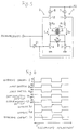
- Figure 1 is a circuit diagram of a magnetic head driving device according to the present invention.
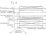
- Figure 2 is a timing chart showing the operation of the magnetic head driving device of Figure 1 .
- Figure 3 is a circuit diagram of another magnetic head driving device according to the present invention.
- Figure 4 is a timing chart showing the operation of the magnetic head driving device of Figure 3 .
- FIG. 5 is a circuit diagram of yet another magnetic head driving device according to the present invention.
- Figure 6 is a timing chart showing the operation of the magnetic head driving device of Figure 5 .
- Figure 7 a circuit diagram of a conventional magnetic head driving device.
- Figure 8 is a circuit diagram of another conventional magnetic head driving device.
- FIG. 1 shows a magnetic head driving device according to the present invention used for a general magnetic recording apparatus.
- the magnetic head driving device includes a first current path 1 and a second current path 2 which are arranged in parallel and are connected to a source terminal 10 .
- the first current path 1 is a circuit having a current source 7 , a resistor R 1 , an auxiliary coil 5 , and a main switch 3 connected in series.
- the second current path 2 is a circuit having a current source 8 , a resistor R 2 , an auxiliary coil 6 , and a main switch 4 connected in series.
- a head coil 9 is connected between the connecting point of the auxiliary coil 5 and the main switch 3 of the first current path 1 and the connecting point of the auxiliary coil 6 and the main switch 4 of the second current path 2 .
- the head coil 9 is a coil for generating a magnetic field with which information is magnetically recorded on a magnetic medium.
- the resistors R 1 and R 2 determine the amount of a recording current I X flowing into the head coil 9 .
- the auxiliary coils 5 and 6 are used for storing electromagnetic energy therein and have an inductance sufficiently larger than that of the head coil 9 .
- the auxiliary coils 5 and 6 have a resistance as small as less than 1 ⁇ , which can be disregarded when compared with the resistance of the resistors R 1 and R 2 which are, for example 10 ⁇ or more.
- the resistances of the resistors R 1 and R 2 are the same, and the inductances of the auxiliary coils 5 and 6 are the same, so that the impedances of the first current path 1 and the second current path 2 are the same.
- the main switches 3 and 4 which are each formed of a MOSFET, for example, are turned ON when control terminals thereof are at a HIGH level.
- a recording signal S input to the magnetic head driving device of the present invention is coupled to the control terminal of the main switch 3 through an AND gate 22 and an OR gate 23 as shown.
- the recording signal S is also coupled to the control terminal of the main switch 4 through an AND gate 24 and an OR gate 25 after first being inverted by an inverter 21 .
- the AND gates 22 and 24 are also provided with a recording operation control signal C 1 as an input to control the magnetic head driving device, essentially selectively masking the recording signal S .
- the recording operation control signal C 1 When the recording operation control signal C 1 is at a LOW level, the respective output signals from the AND gates 22 and 24 will be at a LOW level regardless of the level of the recording signal S , thus turning the main switches 3 and 4 OFF.
- the level of the recording operation control signal C 1 is set HIGH by a controller (not shown) only when a recording operation is performed by the magnetic head driving device.
- the OR gates 23 and 25 are supplied with an idling control signal C 2 as an input to control the magnetic head driving device.
- the idling control signal C 2 is at a HIGH level, the respective signal outputs from the OR gates 23 and 25 are always at a HIGH level regardless of the level of the recording signal S , thus turning the main switches 3 and 4 ON.
- the idling control signal C 2 is set HIGH by the controller (not shown) only for a predetermined period of time before the start of the recording operation by the magnetic head driving device.
- the controller sets the level of the idling control signal C 2 HIGH (e.g., at time t 0 ) to turn both the main switches 3 and 4 ON. This allows the currents I L1 and I L2 to flow into the auxiliary coils 5 and 6 .
- the currents I L1 and I L2 start to flow gradually in accordance with the transient response based on the time constant ⁇ determined by the resistances of the resistors R 1 and R 2 and the inductances of the auxiliary coils 5 and 6 .
- This idling operation lasts for a period of time not less than the time constant, but preferably not much further beyond.
- the currents I L1 and I L2 reach a predetermined level which is high enough to energize the auxiliary coils 5 and 6 . Since the impedances of the first current path 1 and the second current path 2 are the same, the potential difference across the head coil 9 is equal to zero and the recording current I X does not flow into the head coil 9 during the idling operation. As a result, no magnetic field is generated therefrom and thus there is no influence on a recording medium.
- the recording operation starts, whereby the controller sets the level of the idling control signal C 2 LOW and that of the recording operation control signal C 1 HIGH.
- the logic level of the recording signal S i.e., HIGH or LOW
- the recording signal S is inverted by the inverter 21 and is coupled to the control terminal of the main switch 4 .
- the main switches 3 and 4 are alternately turned ON/OFF in accordance with the logic level of the recording signal S .
- the recording current I X flows from the current source 8 through the resistor R 2 and the auxiliary coil 6 into the head coil 9 .
- the recording current I X flows from the current source 7 through the resistor R 1 and the auxiliary coil 5 into the head coil 9 in the reverse direction. A magnetic field in accordance with the recording signal S is thus generated by these reversed flows of the recording current I X .
- the current I L1 flows from the current source 7 of the first current path 1 through the resistor R 1 into the auxiliary coil 5 .
- the current I L2 flows from the current source 8 of the second current path 2 through the resistor R 2 into the auxiliary coil 6 . Accordingly, the auxiliary coils 5 and 6 are energized by the currents I L1 and I L2 , respectively, while these currents are not supplied to the head coil 9 as the recording current I X .
- the level of the recording signal S is reversed to alter the ON/OFF state of the main switches 3 and 4 , a current immediately flows from the respective auxiliary coils 5 and 6 which has stored electromagnetic energy with the current I L1 or I L2 into the head coil 9 since the head coil 9 has a smaller inductance than the auxiliary coils 5 and 6 .
- the recording current I X flowing into the head coil 9 can be reversed at high speed.
- the auxiliary coils 5 and 6 have stored electromagnetic energy during the idling operation before the start of the recording operation, the amount of the recording current I X flowing in the head coil 9 at the start of recording is sufficient.
- the auxiliary coils 5 and 6 can store electromagnetic energy during the idling operation without affecting the recording medium, regardless of the types of recording media which may be used.
- the problem of the insufficient amount of the recording current I X at the start of recording can be prevented.
- Figure 3 shows a second example of the magnetic head driving device according to the present invention used for a magneto-optical recording apparatus employing the magnetic field modulation system.
- the components having similar functions to those in Example 1 are denoted by the same reference numerals as those provided in Figure 1 , and their descriptions are omitted.
- the configuration of the first current path 1 and the second current path 2 arranged in parallel and connected to the source terminal 10 is the same as that of Example 1 shown in Figure 1 .
- the circuit for sending the recording signal S to the control terminals of the main switches 3 and 4 is the same as that of Example 1, except that the OR gates 23 and 25 and the idling control signal C 2 supplied thereto have been eliminated in this example.
- the magnetic head driving device of this example is substantially the same as that of Example 1 when the idling control signal C 2 of Example 1 is fixed at a LOW level.
- An idling operation is performed for a predetermined period of time (t 0 to t 1 ) before the start of recording.
- This idling operation includes setting the level of the recording operation control signal C 1 HIGH at time t 0 using the controller (not shown) before the recording medium is irradiated with laser light, and simultaneously supplying an idling signal as the recording signal S for an idling operation to the magnetic head driving device until time t 1 .
- the idling signal for the idling operation is produced by providing a HIGH-LOW square wave as the recording signal S .
- the frequency of the HIGH-LOW square wave is preferably 3-6 megahertz (MHz).
- the main switches 3 and 4 of the first current path 1 and the second current path 2 are alternately turned ON/OFF repeatedly, so that the absolute value of the recording current I X flowing into the head coil 9 in the alternating directions through the auxiliary coil 5 or 6 gradually increases.
- the auxiliary coils 5 and 6 sufficiently store electromagnetic energy during the predetermined idling period to allow the recording current I X to change direction at high speed. According to experimental tests, it is suitable to set the idling period 1.5 times as large as the time constant ⁇ described in Example 1. During this idling operation, a magnetic field is generated by the recording current I X flowing into the head coil 9 . However, the magneto-optical recording medium will not be affected by the magnetic field unless it is irradiated with high-energy laser light.
- the recording operation starts.
- a specified area on the magneto-optical recording medium corresponding to the location where information is to be recorded is sequentially irradiated with high-energy laser light.
- the recording signal S is supplied to the magnetic head driving device with the recording operation control signal C 1 kept at a HIGH level.
- the main switches 3 and 4 are alternately turned ON/OFF in accordance with the recording signal S , allowing the recording current I X to flow into the head coil 9 in the alternating directions, thus generating a magnetic field.
- the area on the recording medium irradiated with laser light is sequentially magnetized in accordance with the magnetic field generated at that time to effect recording. Since the auxiliary coils 5 and 6 have stored electromagnetic energy during the idling operation, the amount of the recording current I X is sufficiently large at the start of recording to allow high-speed current reverse.
- the problem of insufficient flow of the recording current I X at the start of recording can be prevented without the use of the idling control signal C 2 as in Example 1, although a longer time is required for the idling operation than in Example 1.
- Figure 5 shows a third example of the magnetic head driving device according to the present invention.
- the components having similar functions to those in Example 1 are denoted by the same reference numerals as those in Figure 1 , and their descriptions are omitted.
- the configuration of the first current path 1 and the second current path 2 arranged in parallel and connected to the source terminal 10 is substantially the same as that of Example 1 shown in Figure 1 .
- auxiliary switches 11 and 12 having a structure similar to that of the switches 3 and 4 are connected between the current source 7 and the resistor R 1 and between the current source 8 and the resistor R 2 , respectively; and that the auxiliary coils 5 and 6 share a single magnetic core 5a and are wound so that magnetic fluxes generated by the currents I L1 and I L2 are in the same direction in the magnetic core 5a with polarities as indicated.
- the circuit for sending the recording signal S to the control terminals of the main switches 3 and 4 is substantially same as that of Example 1, except that the recording signal S sent to the control terminal of the main switch 3 is also supplied to the control terminal of the auxiliary switch 12 , and likewise the recording signal S sent to the control terminal of the main switch 4 is also sent to the control terminal of the auxiliary switch 11 .
- the main switch 3 of the first current path 1 and the auxiliary switch 12 of the second current path 2 are ON, while the main switch 4 of the second current path 2 and the auxiliary switch 11 of the first current path 1 are OFF. Accordingly, the current I L1 does not flow into the auxiliary coil 5 of the first current path 1 , but only the current I L2 flows into the auxiliary coil 6 of the second current path 2 , which is used as the recording current I X of the head coil 9 .
- the recording signal S is in LOW level
- the main switch 4 and the auxiliary switch 11 are ON, and the main switch 3 and the auxiliary switch 12 are OFF.
- the current I L2 does not flow in the auxiliary coil 6 , but only the current I L1 flows in the auxiliary coil 5 , which flows into the head coil 9 as the recording current I X in the reverse direction.
- a magnetic field in accordance with the recording signal S is generated from the head coil 9 to effect the magnetic recording.
- the magnetic core 5a has been energized with electromagnetic energy by the current I L1 or I L2 which has flown into the auxiliary coil 5 or 6 . Therefore, when the recording signal S is reversed from HIGH to LOW, for example, the electromagnetic energy stored in the magnetic core 5a is supplied through the auxiliary coil 5 to the head coil 9 as the recording current I X , although the auxiliary coil 5 itself has not stored electromagnetic energy with the current I L1 . Likewise, when the recording signal S is reversed from LOW to HIGH , the electromagnetic energy stored in the magnetic core 5a is supplied through the auxiliary coil 6 to the head coil 9 to flow thereinto in the reverse direction.
- the recording current I X can reverse at high speed in accordance with the reverse of the recording signal S . Furthermore, according to this example, since all of the currents I L1 and I L2 flowing in the auxiliary coils 5 and 6 are used as the recording current I X , no power is wasted.
- the high-speed reverse of the recording current I X flowing into the head coil 9 can be obtained without wasting the currents I L1 and I L'' flowing in the auxiliary coils 5 and 6.
- the magnetic head driving device of the present invention is applicable not only to a magneto-optical recording apparatus employing the magnetic field modulation system, but also to a general magnetic recording apparatus in which information is magnetically recorded on a recording medium by changing an outer magnetic field.
Applications Claiming Priority (4)
| Application Number | Priority Date | Filing Date | Title |
|---|---|---|---|
| JP3341428A JP2859766B2 (ja) | 1991-12-24 | 1991-12-24 | 磁気ヘッド駆動回路 |
| JP341428/91 | 1991-12-24 | ||
| JP34142891 | 1991-12-24 | ||
| EP92311820A EP0550267B1 (de) | 1991-12-24 | 1992-12-24 | Vorrichtung zur Ansteuerung eines Magnetkopfes |
Related Parent Applications (1)
| Application Number | Title | Priority Date | Filing Date |
|---|---|---|---|
| EP92311820A Division EP0550267B1 (de) | 1991-12-24 | 1992-12-24 | Vorrichtung zur Ansteuerung eines Magnetkopfes |
Publications (3)
| Publication Number | Publication Date |
|---|---|
| EP0855704A2 true EP0855704A2 (de) | 1998-07-29 |
| EP0855704A3 EP0855704A3 (de) | 2000-08-16 |
| EP0855704B1 EP0855704B1 (de) | 2002-09-18 |
Family
ID=18346001
Family Applications (2)
| Application Number | Title | Priority Date | Filing Date |
|---|---|---|---|
| EP92311820A Expired - Lifetime EP0550267B1 (de) | 1991-12-24 | 1992-12-24 | Vorrichtung zur Ansteuerung eines Magnetkopfes |
| EP98104433A Expired - Lifetime EP0855704B1 (de) | 1991-12-24 | 1992-12-24 | Magnetkopfantriebsvorrichtung |
Family Applications Before (1)
| Application Number | Title | Priority Date | Filing Date |
|---|---|---|---|
| EP92311820A Expired - Lifetime EP0550267B1 (de) | 1991-12-24 | 1992-12-24 | Vorrichtung zur Ansteuerung eines Magnetkopfes |
Country Status (6)
| Country | Link |
|---|---|
| US (1) | US5351155A (de) |
| EP (2) | EP0550267B1 (de) |
| JP (1) | JP2859766B2 (de) |
| KR (1) | KR0124030B1 (de) |
| CA (1) | CA2085763C (de) |
| DE (2) | DE69232783T2 (de) |
Families Citing this family (9)
| Publication number | Priority date | Publication date | Assignee | Title |
|---|---|---|---|---|
| US5587851A (en) * | 1991-12-24 | 1996-12-24 | Sharp Kabushiki Kaisha | Magnetic head driving device with prerecording energization |
| JPH0729234A (ja) * | 1993-07-07 | 1995-01-31 | Sony Corp | 光磁気記録再生装置 |
| JP3107265B2 (ja) * | 1993-08-06 | 2000-11-06 | キヤノン株式会社 | 磁気ヘッド駆動装置及び磁気記録装置 |
| JPH07182717A (ja) * | 1993-12-24 | 1995-07-21 | Sharp Corp | 光磁気記録再生装置 |
| US5559643A (en) * | 1994-02-28 | 1996-09-24 | Sony Corporation | Apparatus for recording a digital signal onto a recording medium at one of a plurality of data recording rates |
| KR0183824B1 (ko) * | 1995-08-16 | 1999-04-15 | 김광호 | 자기기록장치 및 방법 |
| JPH1186203A (ja) * | 1997-09-03 | 1999-03-30 | Canon Inc | 磁気ヘッド駆動装置及び光磁気記録装置 |
| JP2001176142A (ja) * | 1999-12-16 | 2001-06-29 | Canon Inc | 磁気ヘッド駆動回路及び光磁気記録装置 |
| CN112837887B (zh) * | 2019-11-25 | 2022-09-09 | 北京华航无线电测量研究所 | 一种时分复用体制的局部交变磁场发生装置 |
Citations (8)
| Publication number | Priority date | Publication date | Assignee | Title |
|---|---|---|---|---|
| JPS6394406A (ja) * | 1986-10-07 | 1988-04-25 | Sony Corp | 磁気ヘツド駆動回路 |
| JPS63244402A (ja) * | 1987-03-31 | 1988-10-11 | Sony Corp | 記録用磁界発生回路 |
| EP0304298A2 (de) * | 1987-08-19 | 1989-02-22 | Sony Corporation | Steuerungsschaltung für magnetischen Kopf |
| EP0365891A1 (de) * | 1988-10-22 | 1990-05-02 | Deutsche Thomson-Brandt GmbH | Schaltungsanordnung zur magnetischen oder magneto-optischen Aufzeichnung von Daten auf einem Datenträger |
| WO1990005980A1 (de) * | 1988-11-17 | 1990-05-31 | Deutsche Thomson-Brandt Gmbh | Schaltungsanordnung zur umkehrung eines magnetfeldes |
| JPH03157839A (ja) * | 1989-11-15 | 1991-07-05 | Matsushita Electric Ind Co Ltd | 光磁気ディスク用高周波変調磁界発生装置 |
| EP0519729A2 (de) * | 1991-06-21 | 1992-12-23 | Sharp Kabushiki Kaisha | Treiberschaltung eines Magnetkopfes |
| EP0557094A1 (de) * | 1992-02-19 | 1993-08-25 | Canon Kabushiki Kaisha | Magnetkopg-Antriebsvorrichtung |
Family Cites Families (1)
| Publication number | Priority date | Publication date | Assignee | Title |
|---|---|---|---|---|
| JPS62129905A (ja) * | 1985-11-30 | 1987-06-12 | Toshiba Corp | フロツピ−デイスク装置の磁気ヘツド駆動回路 |
-
1991
- 1991-12-24 JP JP3341428A patent/JP2859766B2/ja not_active Expired - Fee Related
-
1992
- 1992-12-18 CA CA002085763A patent/CA2085763C/en not_active Expired - Fee Related
- 1992-12-18 US US07/993,728 patent/US5351155A/en not_active Expired - Lifetime
- 1992-12-24 DE DE69232783T patent/DE69232783T2/de not_active Expired - Fee Related
- 1992-12-24 EP EP92311820A patent/EP0550267B1/de not_active Expired - Lifetime
- 1992-12-24 KR KR1019920025502A patent/KR0124030B1/ko not_active IP Right Cessation
- 1992-12-24 EP EP98104433A patent/EP0855704B1/de not_active Expired - Lifetime
- 1992-12-24 DE DE69227439T patent/DE69227439T2/de not_active Expired - Fee Related
Patent Citations (8)
| Publication number | Priority date | Publication date | Assignee | Title |
|---|---|---|---|---|
| JPS6394406A (ja) * | 1986-10-07 | 1988-04-25 | Sony Corp | 磁気ヘツド駆動回路 |
| JPS63244402A (ja) * | 1987-03-31 | 1988-10-11 | Sony Corp | 記録用磁界発生回路 |
| EP0304298A2 (de) * | 1987-08-19 | 1989-02-22 | Sony Corporation | Steuerungsschaltung für magnetischen Kopf |
| EP0365891A1 (de) * | 1988-10-22 | 1990-05-02 | Deutsche Thomson-Brandt GmbH | Schaltungsanordnung zur magnetischen oder magneto-optischen Aufzeichnung von Daten auf einem Datenträger |
| WO1990005980A1 (de) * | 1988-11-17 | 1990-05-31 | Deutsche Thomson-Brandt Gmbh | Schaltungsanordnung zur umkehrung eines magnetfeldes |
| JPH03157839A (ja) * | 1989-11-15 | 1991-07-05 | Matsushita Electric Ind Co Ltd | 光磁気ディスク用高周波変調磁界発生装置 |
| EP0519729A2 (de) * | 1991-06-21 | 1992-12-23 | Sharp Kabushiki Kaisha | Treiberschaltung eines Magnetkopfes |
| EP0557094A1 (de) * | 1992-02-19 | 1993-08-25 | Canon Kabushiki Kaisha | Magnetkopg-Antriebsvorrichtung |
Non-Patent Citations (3)
| Title |
|---|
| PATENT ABSTRACTS OF JAPAN vol. 012, no. 331 (P-755), 7 September 1988 (1988-09-07) & JP 63 094406 A (SONY CORP), 25 April 1988 (1988-04-25) * |
| PATENT ABSTRACTS OF JAPAN vol. 013, no. 054 (P-824), 8 February 1989 (1989-02-08) & JP 63 244402 A (SONY CORP), 11 October 1988 (1988-10-11) * |
| PATENT ABSTRACTS OF JAPAN vol. 015, no. 395 (P-1260), 7 October 1991 (1991-10-07) & JP 03 157839 A (MATSUSHITA ELECTRIC IND CO LTD), 5 July 1991 (1991-07-05) * |
Also Published As
| Publication number | Publication date |
|---|---|
| EP0550267B1 (de) | 1998-10-28 |
| KR930014518A (ko) | 1993-07-23 |
| EP0855704A3 (de) | 2000-08-16 |
| DE69227439T2 (de) | 1999-05-12 |
| CA2085763C (en) | 1997-01-14 |
| DE69232783D1 (de) | 2002-10-24 |
| DE69232783T2 (de) | 2003-04-10 |
| JPH05174307A (ja) | 1993-07-13 |
| KR0124030B1 (ko) | 1997-11-28 |
| EP0550267A1 (de) | 1993-07-07 |
| DE69227439D1 (de) | 1998-12-03 |
| CA2085763A1 (en) | 1993-06-25 |
| EP0855704B1 (de) | 2002-09-18 |
| JP2859766B2 (ja) | 1999-02-24 |
| US5351155A (en) | 1994-09-27 |
Similar Documents
| Publication | Publication Date | Title |
|---|---|---|
| CA2081864C (en) | External magnetic field generation apparatus | |
| EP0855704B1 (de) | Magnetkopfantriebsvorrichtung | |
| KR970001977B1 (ko) | 자기-광학 기록 장치 | |
| EP0540275B1 (de) | Schaltungsvorrichtung zur Steuerung eines magnetischen Kopfs | |
| JP3171594B2 (ja) | 磁気光学メモリに記録するために磁界を変調するための制御回路 | |
| JP3365435B2 (ja) | 光磁気記録装置 | |
| US5587851A (en) | Magnetic head driving device with prerecording energization | |
| JPH03157839A (ja) | 光磁気ディスク用高周波変調磁界発生装置 | |
| US5303212A (en) | Low voltage, high current magnetic transducer drive system for digital recording | |
| US5331477A (en) | Low voltage, constant current magnetic transducer drive system for digital recording | |
| JP2880743B2 (ja) | 光磁気記録用外部印加磁界供給装置 | |
| JPH04188404A (ja) | 磁気ヘッド装置 | |
| JPH06231403A (ja) | 光磁気記録用磁気ヘッド駆動回路 | |
| JP2868101B2 (ja) | 磁気ヘッド駆動装置 | |
| JPH0684103A (ja) | 磁気ヘッド装置 | |
| JP2550842B2 (ja) | 高周波変調磁界発生回路 | |
| JP2845085B2 (ja) | 磁気記録装置の高周波変調磁界発生回路 | |
| US6477119B2 (en) | Magnetic head drive circuit including paired auxiliary coils, paired switching elements, and switch element control circuit, and magneto-optical recording device using the same | |
| JPH03272038A (ja) | 磁気ヘッド装置 | |
| JPH03130903A (ja) | 磁気ヘッド装置 | |
| JPH04212702A (ja) | 磁気ヘッド駆動回路 | |
| JPH07114703A (ja) | 磁気ヘッド駆動回路 | |
| JPH06168404A (ja) | 磁気ヘッド駆動回路 | |
| JPH07169002A (ja) | 磁気ヘッド駆動回路 | |
| JPH06131609A (ja) | 磁気ヘッド駆動装置 |
Legal Events
| Date | Code | Title | Description |
|---|---|---|---|
| PUAI | Public reference made under article 153(3) epc to a published international application that has entered the european phase |
Free format text: ORIGINAL CODE: 0009012 |
|
| AC | Divisional application: reference to earlier application |
Ref document number: 550267 Country of ref document: EP |
|
| AK | Designated contracting states |
Kind code of ref document: A2 Designated state(s): DE GB |
|
| RBV | Designated contracting states (corrected) |
Designated state(s): DE GB |
|
| PUAL | Search report despatched |
Free format text: ORIGINAL CODE: 0009013 |
|
| AK | Designated contracting states |
Kind code of ref document: A3 Designated state(s): DE GB |
|
| RIC1 | Information provided on ipc code assigned before grant |
Free format text: 7G 11B 11/10 A, 7H 03K 17/66 B, 7H 03K 17/687 B |
|
| 17P | Request for examination filed |
Effective date: 20001204 |
|
| 17Q | First examination report despatched |
Effective date: 20010529 |
|
| GRAG | Despatch of communication of intention to grant |
Free format text: ORIGINAL CODE: EPIDOS AGRA |
|
| GRAG | Despatch of communication of intention to grant |
Free format text: ORIGINAL CODE: EPIDOS AGRA |
|
| GRAG | Despatch of communication of intention to grant |
Free format text: ORIGINAL CODE: EPIDOS AGRA |
|
| GRAH | Despatch of communication of intention to grant a patent |
Free format text: ORIGINAL CODE: EPIDOS IGRA |
|
| GRAH | Despatch of communication of intention to grant a patent |
Free format text: ORIGINAL CODE: EPIDOS IGRA |
|
| GRAA | (expected) grant |
Free format text: ORIGINAL CODE: 0009210 |
|
| AC | Divisional application: reference to earlier application |
Ref document number: 550267 Country of ref document: EP |
|
| AK | Designated contracting states |
Kind code of ref document: B1 Designated state(s): DE GB |
|
| REG | Reference to a national code |
Ref country code: GB Ref legal event code: FG4D |
|
| REF | Corresponds to: |
Ref document number: 69232783 Country of ref document: DE Date of ref document: 20021024 |
|
| PLBE | No opposition filed within time limit |
Free format text: ORIGINAL CODE: 0009261 |
|
| STAA | Information on the status of an ep patent application or granted ep patent |
Free format text: STATUS: NO OPPOSITION FILED WITHIN TIME LIMIT |
|
| 26N | No opposition filed |
Effective date: 20030619 |
|
| PGFP | Annual fee paid to national office [announced via postgrant information from national office to epo] |
Ref country code: DE Payment date: 20081219 Year of fee payment: 17 |
|
| PGFP | Annual fee paid to national office [announced via postgrant information from national office to epo] |
Ref country code: GB Payment date: 20081224 Year of fee payment: 17 |
|
| GBPC | Gb: european patent ceased through non-payment of renewal fee |
Effective date: 20091224 |
|
| PG25 | Lapsed in a contracting state [announced via postgrant information from national office to epo] |
Ref country code: DE Free format text: LAPSE BECAUSE OF NON-PAYMENT OF DUE FEES Effective date: 20100701 |
|
| PG25 | Lapsed in a contracting state [announced via postgrant information from national office to epo] |
Ref country code: GB Free format text: LAPSE BECAUSE OF NON-PAYMENT OF DUE FEES Effective date: 20091224 |