EP0736402A2 - Fahrzeugklimaanlage - Google Patents
Fahrzeugklimaanlage Download PDFInfo
- Publication number
- EP0736402A2 EP0736402A2 EP96302346A EP96302346A EP0736402A2 EP 0736402 A2 EP0736402 A2 EP 0736402A2 EP 96302346 A EP96302346 A EP 96302346A EP 96302346 A EP96302346 A EP 96302346A EP 0736402 A2 EP0736402 A2 EP 0736402A2
- Authority
- EP
- European Patent Office
- Prior art keywords
- heat exchanger
- air
- refrigerant
- vehicle
- air conditioner
- Prior art date
- Legal status (The legal status is an assumption and is not a legal conclusion. Google has not performed a legal analysis and makes no representation as to the accuracy of the status listed.)
- Granted
Links
Images


Classifications
-
- F—MECHANICAL ENGINEERING; LIGHTING; HEATING; WEAPONS; BLASTING
- F25—REFRIGERATION OR COOLING; COMBINED HEATING AND REFRIGERATION SYSTEMS; HEAT PUMP SYSTEMS; MANUFACTURE OR STORAGE OF ICE; LIQUEFACTION SOLIDIFICATION OF GASES
- F25B—REFRIGERATION MACHINES, PLANTS OR SYSTEMS; COMBINED HEATING AND REFRIGERATION SYSTEMS; HEAT PUMP SYSTEMS
- F25B13/00—Compression machines, plants or systems, with reversible cycle
-
- B—PERFORMING OPERATIONS; TRANSPORTING
- B60—VEHICLES IN GENERAL
- B60H—ARRANGEMENTS OF HEATING, COOLING, VENTILATING OR OTHER AIR-TREATING DEVICES SPECIALLY ADAPTED FOR PASSENGER OR GOODS SPACES OF VEHICLES
- B60H1/00—Heating, cooling or ventilating [HVAC] devices
- B60H1/00314—Arrangements permitting a rapid heating of the heating liquid
-
- B—PERFORMING OPERATIONS; TRANSPORTING
- B60—VEHICLES IN GENERAL
- B60H—ARRANGEMENTS OF HEATING, COOLING, VENTILATING OR OTHER AIR-TREATING DEVICES SPECIALLY ADAPTED FOR PASSENGER OR GOODS SPACES OF VEHICLES
- B60H1/00—Heating, cooling or ventilating [HVAC] devices
- B60H1/00642—Control systems or circuits; Control members or indication devices for heating, cooling or ventilating devices
- B60H1/00814—Control systems or circuits characterised by their output, for controlling particular components of the heating, cooling or ventilating installation
- B60H1/00878—Control systems or circuits characterised by their output, for controlling particular components of the heating, cooling or ventilating installation the components being temperature regulating devices
- B60H1/00899—Controlling the flow of liquid in a heat pump system
- B60H1/00907—Controlling the flow of liquid in a heat pump system where the flow direction of the refrigerant changes and an evaporator becomes condenser
-
- B—PERFORMING OPERATIONS; TRANSPORTING
- B60—VEHICLES IN GENERAL
- B60H—ARRANGEMENTS OF HEATING, COOLING, VENTILATING OR OTHER AIR-TREATING DEVICES SPECIALLY ADAPTED FOR PASSENGER OR GOODS SPACES OF VEHICLES
- B60H1/00—Heating, cooling or ventilating [HVAC] devices
- B60H1/02—Heating, cooling or ventilating [HVAC] devices the heat being derived from the propulsion plant
- B60H1/03—Heating, cooling or ventilating [HVAC] devices the heat being derived from the propulsion plant and from a source other than the propulsion plant
- B60H1/039—Heating, cooling or ventilating [HVAC] devices the heat being derived from the propulsion plant and from a source other than the propulsion plant from air leaving the interior of the vehicle, i.e. heat recovery
-
- B—PERFORMING OPERATIONS; TRANSPORTING
- B60—VEHICLES IN GENERAL
- B60H—ARRANGEMENTS OF HEATING, COOLING, VENTILATING OR OTHER AIR-TREATING DEVICES SPECIALLY ADAPTED FOR PASSENGER OR GOODS SPACES OF VEHICLES
- B60H1/00—Heating, cooling or ventilating [HVAC] devices
- B60H1/00642—Control systems or circuits; Control members or indication devices for heating, cooling or ventilating devices
- B60H1/00814—Control systems or circuits characterised by their output, for controlling particular components of the heating, cooling or ventilating installation
- B60H1/00878—Control systems or circuits characterised by their output, for controlling particular components of the heating, cooling or ventilating installation the components being temperature regulating devices
- B60H2001/00935—Control systems or circuits characterised by their output, for controlling particular components of the heating, cooling or ventilating installation the components being temperature regulating devices comprising four way valves for controlling the fluid direction
-
- F—MECHANICAL ENGINEERING; LIGHTING; HEATING; WEAPONS; BLASTING
- F25—REFRIGERATION OR COOLING; COMBINED HEATING AND REFRIGERATION SYSTEMS; HEAT PUMP SYSTEMS; MANUFACTURE OR STORAGE OF ICE; LIQUEFACTION SOLIDIFICATION OF GASES
- F25B—REFRIGERATION MACHINES, PLANTS OR SYSTEMS; COMBINED HEATING AND REFRIGERATION SYSTEMS; HEAT PUMP SYSTEMS
- F25B2313/00—Compression machines, plants or systems with reversible cycle not otherwise provided for
- F25B2313/004—Outdoor unit with water as a heat sink or heat source
-
- F—MECHANICAL ENGINEERING; LIGHTING; HEATING; WEAPONS; BLASTING
- F25—REFRIGERATION OR COOLING; COMBINED HEATING AND REFRIGERATION SYSTEMS; HEAT PUMP SYSTEMS; MANUFACTURE OR STORAGE OF ICE; LIQUEFACTION SOLIDIFICATION OF GASES
- F25B—REFRIGERATION MACHINES, PLANTS OR SYSTEMS; COMBINED HEATING AND REFRIGERATION SYSTEMS; HEAT PUMP SYSTEMS
- F25B2313/00—Compression machines, plants or systems with reversible cycle not otherwise provided for
- F25B2313/025—Compression machines, plants or systems with reversible cycle not otherwise provided for using multiple outdoor units
- F25B2313/0252—Compression machines, plants or systems with reversible cycle not otherwise provided for using multiple outdoor units with bypasses
-
- F—MECHANICAL ENGINEERING; LIGHTING; HEATING; WEAPONS; BLASTING
- F25—REFRIGERATION OR COOLING; COMBINED HEATING AND REFRIGERATION SYSTEMS; HEAT PUMP SYSTEMS; MANUFACTURE OR STORAGE OF ICE; LIQUEFACTION SOLIDIFICATION OF GASES
- F25B—REFRIGERATION MACHINES, PLANTS OR SYSTEMS; COMBINED HEATING AND REFRIGERATION SYSTEMS; HEAT PUMP SYSTEMS
- F25B2313/00—Compression machines, plants or systems with reversible cycle not otherwise provided for
- F25B2313/027—Compression machines, plants or systems with reversible cycle not otherwise provided for characterised by the reversing means
- F25B2313/02741—Compression machines, plants or systems with reversible cycle not otherwise provided for characterised by the reversing means using one four-way valve
-
- F—MECHANICAL ENGINEERING; LIGHTING; HEATING; WEAPONS; BLASTING
- F25—REFRIGERATION OR COOLING; COMBINED HEATING AND REFRIGERATION SYSTEMS; HEAT PUMP SYSTEMS; MANUFACTURE OR STORAGE OF ICE; LIQUEFACTION SOLIDIFICATION OF GASES
- F25B—REFRIGERATION MACHINES, PLANTS OR SYSTEMS; COMBINED HEATING AND REFRIGERATION SYSTEMS; HEAT PUMP SYSTEMS
- F25B2700/00—Sensing or detecting of parameters; Sensors therefor
- F25B2700/21—Temperatures
- F25B2700/2106—Temperatures of fresh outdoor air
Definitions
- the present invention generally relates to an air conditioning system, such as for use in cooling and heating passenger compartments in automotive vehicles, and more particularly, to an air conditioning system having a heat exchanger accelerating system for more efficiently cooling and heating automobile passenger compartments.
- a heat pump circuit may be used in an automobile air conditioning system to improve the cooling and heating efficiency of the system in the outside air inlet mode of operation.
- Japanese Patent Application No. 62-181909 describes an automobile air conditioning system that includes a heat pump circuit.
- a first heat exchanger is disposed in the passenger compartment and is used as a condenser.
- a second heat exchanger is disposed in the engine compartment and is used as an evaporator.
- Fig. 1 illustrates a heat pump-type automotive air conditioning system.
- Air conditioner 100 includes a variable displacement motor compressor 1, an external heat exchanger 3, and an internal heat exchanger 4. Air for air conditioning is conducted into the interior of the vehicle through a duct 10. External heat exchanger 3 is positioned outside of duct 10, and internal heat exchanger 4 is positioned inside of duct 10.
- First, second, third, and fourth openings of four-way valve 2 are connected to the discharge port of compressor 1, a first port of internal heat exchanger 4, the suction port of compressor 1, and a first port of external heat exchanger 3, respectively.
- a second port of external heat exchanger 3 is connected to the inlet of a receiver 9 via a first check valve 7.
- the outlet of receiver 9 is connected to internal heat exchanger 4 via a first expansion valve 5.
- a second expansion valve 6 is provided between the outlet of receiver 9 and the second port of external heat exchanger 3.
- the second port of internal heat exchanger 4 is connected to the inlet port of receiver 9 via a second check valve 8.
- Duct 10 has an outside air inlet port and an inside air inlet port. The balance between outside air and inside air to be drawn into duct 10 is adjusted by a switching damper 12. A motor fan 11 is positioned in duct 10 as a means for drawing outside air into the interior of the vehicle.
- Fig. 1 the solid arrows indicate the direction of refrigerant flow when the heat pump circuit is used for cooling air, and the dashed arrows indicate the direction of refrigerant flow when the heat pump circuit is used for heating.
- four-way valve 2 is switched (solid lines in valve 2) to configure the heat pump circuit as an air cooling system.
- the refrigerant When air cooling is performed, the refrigerant is circulated from compressor 1 via four-way valve 2 to the first port of external heat exchanger 3, from the second port of external heat exchanger 3 to the inlet of receiver 9 via check-valve 7, from the outlet of receiver 9 via expansion valve 5 to the second port of internal exchanger 4, and from the first port of internal heat exchanger 4 via four-way valve 2 to compressor 1, as shown by the solid line arrows in Fig. 1.
- the inside, e.g. , recycled, or outside, e.g. , fresh, air is introduced into duct 10 through damper 12 and passes through internal heat exchanger 4 due to the operation of motor fan 11.
- internal heat exchanger 4 is utilized as an evaporator.
- the inside or outside air exchanges heat with the refrigerant in internal heat exchanger 4, and the refirgerant vaporizes due to its absorption of heat from the inside or outside air.
- the inside or outside air which is thus cooled, is blown into passenger compartment 13, whereby passenger compartment 13 is cooled. Subsequently, the air in passenger compartment 13 is vented to the outside of the automobile through ventilation duct 14,
- the refrigerant is circulated from compressor 1 via four-way valve 2 to the first port of internal heat exchanger 4, from the second port of internal heat exchanger 4 via check valve 8 to the inlet of receiver 9, from the outlet of receiver 9 via expansion valve 6 to the second port of external heat exchanger 3, and from the first port of external heat exchanger 3 via four-way valve 2 to compressor 1, as shown by the dashed line arrows in Fig. 1.
- the inside or outside air again is introduced into duct 10 through damper 12 and passes through internal heat exchanger 4 due to the operation of motor fan 11.
- internal heat exchanger 4 is utilized as a condenser.
- the inside or outside air exchanges heat with the refrigerant in internal heat exchanger 4, and the refrigerant is condensed due to its loss of heat to the inside or outside air in duct 10.
- the inside or outside air which is thus heated, is then blown into passenger compartment 13, whereby passenger compartment 13 is heated. Subsequently, the air in passenger compartment 13 is vented to the outside of the vehicle through ventilation duct 14.
- such air conditioning system results in the loss of energy, represented by the calories expended in heating or cooling air blown into the passenger compartment, which the air that is vented outside of the vehicle includes implicitly.
- the air conditioning system loses this energy outside of the vehicle when the system exhausts unpleasant, e.g. , too hot or too cold, and stale air to the outside of the vehicle. Therefore, such heat pump systems consume additional energy to compensate for this vented air.
- the present invention discloses an air conditioner for a vehicle including a heat pump system capable of heating or cooling a vehicle compartment.
- the air conditioner includes a ventilation passage for conducting air in a vehicle compartment outside of the vehicle.
- the heat pump system includes an external heat exchanger mounted outside the compartment; an internal heat exchanger mounted inside the compartment, which is coupled to the external heat exchanger; a compressor disposed in a refrigerant conduit, wherein the refrigerant conduit places the internal and external heat exchangers in communication to transport refrigerant; and a valve mechanism positioned between the compressor and the internal and external heat exchangers and having at least two positions, a first position, which enables refrigerant to flow between the internal and external heat exchangers in a first direction, and a second position, which enables refrigerant to flow in a second direction opposite to the first direction.
- An accelerating system is provided within the heat pump system for accelerating the condensation or the evaporation a refrigerant during air beating or air cooling, respectively, by using energy recovered from air being exhausted outside of the vehicle through the ventilation passage.
- the accelerating system may include a first heat exchanger, which is positioned in parallel to the external heat exchanger and connected to a second heat exchanger, which is disposed in the ventilation passage for exchanging heat between a working fluid with air, which then is exhausted outside of the vehicle through the ventilation passage, and a pump disposed between the first and second heat exchangers for circulating the working fluid.
- Fig. 1 is a schematic view of an air conditioner for vehicles including a refrigerant circuit diagram according to an embodiment of the prior art.
- Fig. 2 is a schematic view of an air conditioner for vehicles including a refrigerant circuit diagram according to a first embodiment of the present invention
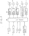
- Fig. 3 is a block diagram of an a control circuit of the air conditioner depicted in Fig. 2 .
- Fig. 4 is a flowchart depicting steps for control of the thermal energy recovery system depicted in Fig. 2 .
- Fig. 5 is a schematic view of an air conditioner for vehicles including a refrigerant circuit diagram according to a second embodiment of the present invention.
- FIG. 2 an air conditioner for a heat pump-type refrigerant circuit is depicted in accordance with a first embodiment.
- the same numerals are used in Fig. 2 to denote corresponding elements depicted in Fig. 1. Thus, a further detailed explanation of those elements is here omitted.
- air conditioner 200 includes a first heat exchanger 15 positioned in parallel to external heat exchanger 3 in a refrigerant circuit.
- First heat exchanger 15 includes refrigerant passageway 15a exchanging heat with the refrigerant and heat medium passageway 15b for exchanging heat with the working fluid.
- Solenoid valve 16 may be provided in the refrigerant circuit for closing and opening the path of the refrigerant into refrigerant passageway 15a of first heat exchanger 17 which is disposed in ventilation duct 14 for recovering the energy, e.g. , the calories expended to heat or cool the vented air, which air is exhausted to the outside of the vehicle through ventilation duct 14.
- Second heat exchanger 17 is provided in working fluid circuit 22 which connects first heat exchanger 15 with second heat exchanger 17.
- Circulating pump 18 is provided in working fluid passageway 22 to circulate a cooling/heating medium, such as water or brine, between second heat exchanger 17 and first heat exchanger 15.
- air conditioner 200 may include a first temperature sensor 19, such as a thermal switch or a thermistor, which is provided outside of the vehicle for measuring the outside air temperature.
- a second temperature sensor 20 is provided at a position upsteam of first heat exchanger 15 for detecting the temperature of the cooling/heating medium flowing into heat exchanger 15.
- air conditioner 200 may include a plurality of valves for switching the flow of the refrigerant, as an alternative to four-way valve 2.
- Fig. 3 depicts a control circuit suitable for use in air conditioner 200.
- An air conditioner switch 30, a conditioning temperature setting device 34, and a selector 31 for selecting an operating mode, e.g. , cooling or heating, are connected to a control unit 35, such as a microcomputer.
- Air conditioning switch 30 initiates the operation of air conditioner 200.
- Conditioning temperature setting device 34 may have a lever, buttons, or the like, for setting an air temperature to be controlled, and the temperature for air conditioning may be selected and set by the operation of the conditioning temperature setting device 34.
- Selector 31 for selecting an operating mode may have a switch lever capable of changing the selection between a "cool" position and a "heat" position.
- control unit 35 may have a CPU, ROMs, RAMs, and the like, and suitable software for the control of switching conditions of the solenoid valves, as well as software for the control in the ROMs.
- Control unit 35 sends control signals to a compressor driving circuit 36, a pump driving circuit 37, a four-way driving circuit 38, a solenoid valve driving circuit 39, and a fan driving circuit 40.
- Compressor driving circuit 36 controls the rotational speed of compressor 1 in response to the rotational speed signal sent from control unit 35.
- Pump driving circuit 37 controls the activation and deactivation of pump 18 in response to the signals from air conditioner switch 30.
- Solenoid valve driving circuit 39 controls the opening and closing of the solenoid valve 2 in response to the detected signals of temperature sensors 19 and 20.
- Fan driving circuit 40 controls the volume of air supplied by motor fan 11 in response to an air volume signal sent from control unit 35.
- four-way valve 2 is switched as indicated by the solid lines in Fig. 1.
- compressor 1 and pump 18 are activated.
- the refrigerant discharged from compressor 1 flows to external heat exchanger 3 and is condensed therein.
- the condensed refrigerant flows to first expansion valve 5 and to internal heat exchanger 4 through first check valve 7 and receiver 9 and is evaporated therein.
- the evaporated refrigerant finally flows into compressor 1 through four-way valve 2.
- the cooling of passenger compartment 13 may be accomplished utilizing the heat-absorbing action of the refrigerant at internal heat exchanger 4.
- the air in passenger compartment 13 is then continuously vented to the outside of the vehicle through ventilation duct 14.
- Second heat exchanger 17 recovers energy which this vented air implicity includes, so that the heating/cooling medium within second heat exchanger 17 exchanges heat with the air passing through ventilation duct 14. Further, energy recovered by second heat exchanger 17 and carried by the heating/cooling medium is circulated to working fluid passageway 15b of first heat exchanger 15 through working fluid circuit 22 by pump 18.
- four-way valve 2 is switched as indicated by the dashed lines in Fig. 2 .
- compressor 1 and pump 18 are again activated.
- the refrigerant discharged from compressor 1 flows to internal heat exchanger 4 and is evaporated therein.
- the evaporated refrigerant then flows to second expansion valve 6 and to external heat exchanger 3 through second check valve 8 and receiver 9 and is condensed therein.
- the condensed refrigerant finally flows into compressor 1 through four-way valve 2.
- the heating of passenger compartment 13 may be accomplished by the radiating action of the refrigerant at internal heat exchanger 4.
- the air within passenger compartment 13 is then continuously vented outside of the vehicle through ventilation duct 14.
- Second heat exchanger 17 recovers energy which this vented air implicitly includes, so that the heating/cooling medium within second heat exchanger 17 exchanges heat with the air passing through ventilation duct 14. Further, energy recovered by second heat exchanger 17 and carried by the heating/cooling medium is circulated to working fluid passageway 15b of first heat exchanger 15 through working fluid circuit 22 by pump 18.
- solenoid valve 16 is opened, and a portion of the refrigerant discharged from compressor 1 flows into refrigerant passageway 15a of first exchanger 15.
- air conditioner 200 is not provided with solenoid valve 16, the portion of the refrigerant discharged from compressor 1 may constantly flow into refrigerant passageway 15a of first hcat exchanger 15.
- second hcat exchanger 17 recovers energy which the air exhausted to the outside of the vehicle through ventilation duct 14 implicitly includes.
- such an air conditioning system accelerates the condensation of the refrigerant therein over that in heat pump system.
- such an air conditioning system accelerates the evaporation of the refrigerant therein over that in heat pump system. Therefore, such an air conditioning system increases the heating and cooling ability by obtaining high endothermic and radiating efficiency. As a result, such a system may reduce the energy expenditure necessary to maintain a constant temperature in the passenger compartment of the vehicle.
- FIG. 5 a second embodiment of the present invention is depicted. Elements similar to those discussed above are designated with the same reference numerals, and the following discussion focuses primarily on the features of the second embodiment.
- An external heat exchanger 33 is disposed in ventilation duct 14 for recovering energy from air which is exhausted outside of the vehicle through ventilation duct 14, Solenoid valve 37 may be provided in the refrigerant circuit for closing and opening the path of the refrigerant flowing into external heat exchanger 33.
- second temperature sensor 30 is provided at a position upstream of external heat exchanger 33 for detecting the temperature of the refrigerant flown into external heat exchanger 33. Therefore, external heat exchanger 33 may recover energy which the air exhausted to the outside of the vehicle through ventilation duct 14 implicitly includes.
- such an air conditioning system accelerates the condensation of the refrigerant therein over that in heat pump system.
- the heating mode of operation such an air conditioning system accelerates the evaporation of the refrigerant therein over that in heat pump system.
Applications Claiming Priority (3)
| Application Number | Priority Date | Filing Date | Title |
|---|---|---|---|
| JP8136095 | 1995-04-06 | ||
| JP08136095A JP3485379B2 (ja) | 1995-04-06 | 1995-04-06 | 車両用空気調和装置 |
| JP81360/95 | 1995-04-06 |
Publications (3)
| Publication Number | Publication Date |
|---|---|
| EP0736402A2 true EP0736402A2 (de) | 1996-10-09 |
| EP0736402A3 EP0736402A3 (de) | 1997-10-22 |
| EP0736402B1 EP0736402B1 (de) | 2001-01-03 |
Family
ID=13744182
Family Applications (1)
| Application Number | Title | Priority Date | Filing Date |
|---|---|---|---|
| EP96302346A Expired - Lifetime EP0736402B1 (de) | 1995-04-06 | 1996-04-02 | Fahrzeugklimaanlage |
Country Status (4)
| Country | Link |
|---|---|
| US (2) | US5749235A (de) |
| EP (1) | EP0736402B1 (de) |
| JP (1) | JP3485379B2 (de) |
| DE (1) | DE69611394T2 (de) |
Cited By (5)
| Publication number | Priority date | Publication date | Assignee | Title |
|---|---|---|---|---|
| FR2755645A1 (fr) * | 1996-11-12 | 1998-05-15 | Valeo Climatisation | Dispositif de climatisation de vehicule avec boucle de chauffage comprenant un compresseur a cylindree variable |
| EP2524829A1 (de) * | 2010-01-15 | 2012-11-21 | Mitsubishi Heavy Industries, Ltd. | Klimaanlage für ein fahrzeug und antriebsregelungsverfahren dafür |
| CN103998265A (zh) * | 2011-12-14 | 2014-08-20 | 空中客车德国运营有限责任公司 | 客舱中的热空气分配系统的温度调节 |
| DE102019115416A1 (de) * | 2019-06-06 | 2020-12-10 | Konvekta Aktiengesellschaft | Heiz- und Klimaanlage mit Nutzung von Abluft |
| EP3895921A1 (de) | 2020-04-18 | 2021-10-20 | Konvekta Aktiengesellschaft | Heiz- und/oder klimaanlage mit verbesserter luftbehandlung und verfahren dazu |
Families Citing this family (36)
| Publication number | Priority date | Publication date | Assignee | Title |
|---|---|---|---|---|
| US5904052A (en) * | 1996-09-02 | 1999-05-18 | Denso Corporation | Brine type air conditioning apparatus |
| US6263689B1 (en) | 1998-10-29 | 2001-07-24 | Taylor Made Environmental, Inc. | Chilled water marine air conditioning |
| DE19860057C5 (de) * | 1998-12-23 | 2009-03-05 | Valeo Klimasysteme Gmbh | Klimaanlage für ein Fahrzeug mit einem Kältespeicher |
| JP2001207960A (ja) * | 2000-01-25 | 2001-08-03 | Toyota Autom Loom Works Ltd | 空気調和装置 |
| DE10006513B4 (de) * | 2000-02-15 | 2014-12-24 | Behr Gmbh & Co. Kg | Klimaanlage für ein Kraftfahrzeug mit Wärmepumpen- und/oder Reheat-Betriebsart |
| JP4465903B2 (ja) * | 2000-04-28 | 2010-05-26 | 株式会社デンソー | 車両用空調装置 |
| KR100357988B1 (ko) * | 2000-05-08 | 2002-10-25 | 진금수 | 히트 펌프식 냉·난방장치 |
| DE10029934A1 (de) * | 2000-06-17 | 2002-01-03 | Behr Gmbh & Co | Klimaanlage mit Klimatisierungs- und Wärmepumpenmodus |
| US6494052B1 (en) * | 2000-08-04 | 2002-12-17 | Trans/Air Manufacturing Corp. | Self contained electrical heat pump HVAC unit |
| US6370903B1 (en) | 2001-03-14 | 2002-04-16 | Visteon Global Technologies, Inc. | Heat-pump type air conditioning and heating system for fuel cell vehicles |
| DE10140311A1 (de) * | 2001-08-16 | 2003-02-27 | Behr Gmbh & Co | Klimaanlage |
| FR2830926B1 (fr) * | 2001-10-12 | 2004-04-02 | Peugeot Citroen Automobiles Sa | Dispositif de regulation thermique pour vehicule automobile, notamment de type electrique ou hybride |
| US20030102113A1 (en) * | 2001-11-30 | 2003-06-05 | Stephen Memory | Heat exchanger for providing supercritical cooling of a working fluid in a transcritical cooling cycle |
| NO320664B1 (no) * | 2001-12-19 | 2006-01-16 | Sinvent As | System for oppvarming og kjoling av kjoretoy |
| JP4312039B2 (ja) * | 2003-12-05 | 2009-08-12 | 昭和電工株式会社 | 超臨界冷媒の冷凍サイクルを有する車両用空調関連技術 |
| JP3781046B2 (ja) * | 2004-07-01 | 2006-05-31 | ダイキン工業株式会社 | 空気調和装置 |
| US8641490B2 (en) * | 2007-04-09 | 2014-02-04 | Nissan North America, Inc. | Vehicle air recirculation control device |
| JP5136881B2 (ja) * | 2007-07-17 | 2013-02-06 | 株式会社ヴァレオジャパン | 車両用空調装置 |
| JP2009023566A (ja) * | 2007-07-20 | 2009-02-05 | Valeo Thermal Systems Japan Corp | 換気、空調及び排気熱回収利用兼用型ユニット及び車両用空調装置 |
| JP4597180B2 (ja) * | 2007-11-06 | 2010-12-15 | 本田技研工業株式会社 | 車両用空調システム |
| JP2009149288A (ja) * | 2007-11-28 | 2009-07-09 | Nissan Motor Co Ltd | 車両用空調装置 |
| KR20090122157A (ko) * | 2008-05-23 | 2009-11-26 | 송세흠 | 온도 구배와 물을 이용한 공기 소스의 열교환 시스템 및 방법 |
| JP5142032B2 (ja) * | 2008-07-01 | 2013-02-13 | 株式会社ヴァレオジャパン | 車両用空調装置 |
| JP2010023547A (ja) * | 2008-07-15 | 2010-02-04 | Calsonic Kansei Corp | 換気負荷低減装置およびそれを用いた自動車用空調装置 |
| JP5346528B2 (ja) * | 2008-09-16 | 2013-11-20 | カルソニックカンセイ株式会社 | 車両用空気調和システム |
| JP5210803B2 (ja) * | 2008-11-04 | 2013-06-12 | カルソニックカンセイ株式会社 | 車両用排気熱回収システム |
| JP5297154B2 (ja) * | 2008-11-06 | 2013-09-25 | 三菱重工業株式会社 | 車両空調システムおよびその運転制御方法 |
| US8899062B2 (en) | 2011-02-17 | 2014-12-02 | Delphi Technologies, Inc. | Plate-type heat pump air conditioner heat exchanger for a unitary heat pump air conditioner |
| JP5815284B2 (ja) * | 2011-05-20 | 2015-11-17 | 株式会社日本自動車部品総合研究所 | 冷却装置 |
| JP2014037181A (ja) * | 2012-08-13 | 2014-02-27 | Calsonic Kansei Corp | 電動車両用熱管理システム |
| JP6540180B2 (ja) * | 2015-04-14 | 2019-07-10 | 株式会社デンソー | 車両用熱管理システム |
| CN105691146A (zh) * | 2016-01-14 | 2016-06-22 | 南京航空航天大学 | 车辆空调系统及其工作方法 |
| US9694647B1 (en) * | 2016-03-22 | 2017-07-04 | Trans/Air Manufacturing Corp. | Highly integrated relay for HVAC systems in large vehicles |
| US10428713B2 (en) | 2017-09-07 | 2019-10-01 | Denso International America, Inc. | Systems and methods for exhaust heat recovery and heat storage |
| GB2575629A (en) * | 2018-07-11 | 2020-01-22 | Dyson Automotive Res And Development Limited | A vehicle air conditioning system |
| FR3121202B1 (fr) * | 2021-03-23 | 2023-11-03 | Psa Automobiles Sa | Dispositif de climatisation reversible pour vehicule automobile et procede d’implantation d’un tel dispositif |
Citations (5)
| Publication number | Priority date | Publication date | Assignee | Title |
|---|---|---|---|---|
| JPS62181909A (ja) * | 1986-02-04 | 1987-08-10 | Toyo Radiator Kk | 車両用ヒ−トポンプ型空調方法 |
| FR2621867A1 (fr) * | 1987-10-16 | 1989-04-21 | Valeo | Installation de chauffage et de climatisation pour vehicule automobile comportant un generateur de chaleur |
| EP0356716A1 (de) * | 1988-07-29 | 1990-03-07 | Sanden Corporation | Fahrzeugklimaanlage |
| EP0566475A1 (de) * | 1992-04-16 | 1993-10-20 | Valeo Climatisation | Klimaanlage für ein elektrisches Fahrzeug |
| US5330385A (en) * | 1991-12-04 | 1994-07-19 | Honda Giken Kogyo Kabushiki Kaisha | Air conditioning system suitable for use in an electric vehicle |
Family Cites Families (39)
| Publication number | Priority date | Publication date | Assignee | Title |
|---|---|---|---|---|
| US2479170A (en) * | 1947-05-07 | 1949-08-16 | Leon L Kuempel | Refrigerating apparatus for vehicles |
| US2575325A (en) * | 1948-02-14 | 1951-11-20 | American Gas And Electric Comp | Heat pump system |
| US2922290A (en) * | 1953-11-27 | 1960-01-26 | Thomas W Carraway | Air conditioning system |
| GB1314341A (en) * | 1969-08-07 | 1973-04-18 | Fisons Scient App Ltd | Refrigeration system |
| US3817054A (en) * | 1972-12-14 | 1974-06-18 | Heatransfer Corp | Automobile air conditioning system |
| US4065938A (en) * | 1976-01-05 | 1978-01-03 | Sun-Econ, Inc. | Air-conditioning apparatus with booster heat exchanger |
| DE2601127A1 (de) * | 1976-01-14 | 1977-07-28 | Karl Weiss Giessen Fabrik Elek | Klimasystem mit waermetauschern, insbesondere zur rueckgewinnung der fortluftwaerme |
| SE410512B (sv) * | 1976-02-03 | 1979-10-15 | Atomenergi Ab | Vermepumpanordning |
| US4100763A (en) * | 1976-06-21 | 1978-07-18 | International Telephone & Telegraph Corporation | Multi-source heat pump HVAC system |
| US4051692A (en) * | 1976-10-12 | 1977-10-04 | Paul Ku | Cooling apparatus for automobile passenger compartment |
| US4163369A (en) * | 1978-05-11 | 1979-08-07 | Charles Owen | Air-to-air heat pump |
| CA1101231A (en) * | 1978-05-18 | 1981-05-19 | William H. Beacham | Heat transfer control circuit for a heat pump |
| DE3018046A1 (de) * | 1979-05-12 | 1980-11-20 | Mckirdy | Temperatur-regelsystem |
| JPS5711108A (en) * | 1980-06-26 | 1982-01-20 | Nippon Denso Co Ltd | Air conditioner for vehicle |
| US4494597A (en) * | 1980-11-05 | 1985-01-22 | Nippon Soken, Inc. | Ventilating device for automotive vehicle |
| JPS57126709A (en) * | 1981-01-26 | 1982-08-06 | Mitsubishi Motors Corp | Car air conditioner |
| JPS57178913A (en) * | 1981-04-27 | 1982-11-04 | Diesel Kiki Co Ltd | Car air-conditioner |
| JPS5826617A (ja) * | 1981-08-07 | 1983-02-17 | Nippon Denso Co Ltd | カ−エアコン制御装置 |
| DD205507A1 (de) * | 1982-02-09 | 1983-12-28 | Masch Und Apparatebau Veb | Anlagenschaltung fuer ein rekuperatives zirkulationssytem zur freien kuehlung |
| US4493193A (en) * | 1982-03-05 | 1985-01-15 | Rutherford C. Lake, Jr. | Reversible cycle heating and cooling system |
| DE3237275C1 (de) * | 1982-10-08 | 1984-04-19 | Daimler-Benz Ag, 7000 Stuttgart | Vorrichtung zum Heizen,Lueften und Kuehlen eines Passagier- und/oder Nutzraumes von Fahrzeugen |
| JPS59229118A (ja) * | 1984-04-16 | 1984-12-22 | Matsushita Electric Ind Co Ltd | 空気調和機の運転制御装置 |
| JPS6146719A (ja) * | 1984-08-10 | 1986-03-07 | Aisin Warner Ltd | 4輪駆動用自動変速機 |
| JPS6150013U (de) * | 1984-09-06 | 1986-04-04 | ||
| JPS61178216A (ja) * | 1985-02-01 | 1986-08-09 | Sanden Corp | 車輛用空調装置における可変容量圧縮機の制御装置 |
| JPS61205511A (ja) * | 1985-03-08 | 1986-09-11 | Nissan Motor Co Ltd | 自動車用加湿装置 |
| JPS62184916A (ja) * | 1986-02-07 | 1987-08-13 | Sanden Corp | 可変容量圧縮機を有する冷房装置 |
| US4779425A (en) * | 1986-05-14 | 1988-10-25 | Sanden Corporation | Refrigerating apparatus |
| AT391933B (de) * | 1986-08-14 | 1990-12-27 | Altexa Lueftungstechnische Anl | Klima- und lueftungsgeraet zum einbau in eine wand, fenster oder dergleichen |
| JPS63150257U (de) * | 1987-03-20 | 1988-10-03 | ||
| JPS63164017U (de) * | 1987-04-15 | 1988-10-26 | ||
| US4763564A (en) * | 1987-04-17 | 1988-08-16 | Ford Motor Company | Multiple unit automotive climate control system |
| US5284025A (en) * | 1991-06-17 | 1994-02-08 | Matsushita Electric Industrial Co., Ltd. | Air conditioning apparatus for an electrically-powered motor vehicle |
| DE4209188C2 (de) * | 1992-03-20 | 1994-02-03 | Kulmbacher Klimageraete | Anordnung zur Klimatisierung von Räumen, insbesondere der Fahrgastzelle von Kraftfahrzeugen |
| JPH06135221A (ja) * | 1992-10-27 | 1994-05-17 | Nippondenso Co Ltd | 空調装置 |
| JP3321871B2 (ja) * | 1993-01-12 | 2002-09-09 | 松下電器産業株式会社 | 車両用ヒートポンプ式空調装置 |
| JP3271347B2 (ja) * | 1993-01-13 | 2002-04-02 | 松下電器産業株式会社 | 車両用ヒートポンプ式空調装置 |
| JPH07182515A (ja) * | 1993-12-24 | 1995-07-21 | Canon Inc | ラベル付け回路 |
| FR2721863B1 (fr) * | 1994-06-29 | 1996-08-23 | Valeo Thermique Habitacle | Dispositif de reglage de la temperature dans l'habitacle d'un vehicule a moteur electrique |
-
1995
- 1995-04-06 JP JP08136095A patent/JP3485379B2/ja not_active Expired - Fee Related
-
1996
- 1996-04-02 US US08/626,378 patent/US5749235A/en not_active Expired - Lifetime
- 1996-04-02 EP EP96302346A patent/EP0736402B1/de not_active Expired - Lifetime
- 1996-04-02 DE DE69611394T patent/DE69611394T2/de not_active Expired - Lifetime
-
1997
- 1997-09-23 US US08/933,737 patent/US6079218A/en not_active Expired - Lifetime
Patent Citations (5)
| Publication number | Priority date | Publication date | Assignee | Title |
|---|---|---|---|---|
| JPS62181909A (ja) * | 1986-02-04 | 1987-08-10 | Toyo Radiator Kk | 車両用ヒ−トポンプ型空調方法 |
| FR2621867A1 (fr) * | 1987-10-16 | 1989-04-21 | Valeo | Installation de chauffage et de climatisation pour vehicule automobile comportant un generateur de chaleur |
| EP0356716A1 (de) * | 1988-07-29 | 1990-03-07 | Sanden Corporation | Fahrzeugklimaanlage |
| US5330385A (en) * | 1991-12-04 | 1994-07-19 | Honda Giken Kogyo Kabushiki Kaisha | Air conditioning system suitable for use in an electric vehicle |
| EP0566475A1 (de) * | 1992-04-16 | 1993-10-20 | Valeo Climatisation | Klimaanlage für ein elektrisches Fahrzeug |
Non-Patent Citations (1)
| Title |
|---|
| PATENT ABSTRACTS OF JAPAN vol. 012, no. 027 (M-662), 27 January 1988 & JP 62 181909 A (TOYO RADIATOR KK), 10 August 1987, * |
Cited By (10)
| Publication number | Priority date | Publication date | Assignee | Title |
|---|---|---|---|---|
| FR2755645A1 (fr) * | 1996-11-12 | 1998-05-15 | Valeo Climatisation | Dispositif de climatisation de vehicule avec boucle de chauffage comprenant un compresseur a cylindree variable |
| US6109046A (en) * | 1996-11-12 | 2000-08-29 | Valeo Climatisation | Air conditioning apparatus for a vehicle with a heating loop including a variable output compressor |
| EP2524829A1 (de) * | 2010-01-15 | 2012-11-21 | Mitsubishi Heavy Industries, Ltd. | Klimaanlage für ein fahrzeug und antriebsregelungsverfahren dafür |
| EP2524829A4 (de) * | 2010-01-15 | 2014-05-14 | Mitsubishi Heavy Ind Ltd | Klimaanlage für ein fahrzeug und antriebsregelungsverfahren dafür |
| US8997503B2 (en) | 2010-01-15 | 2015-04-07 | Mitsubishi Heavy Industries, Ltd. | Vehicle air-conditioning system and operation control method therefor |
| CN103998265A (zh) * | 2011-12-14 | 2014-08-20 | 空中客车德国运营有限责任公司 | 客舱中的热空气分配系统的温度调节 |
| CN103998265B (zh) * | 2011-12-14 | 2016-08-24 | 空中客车德国运营有限责任公司 | 客舱中的热空气分配系统的温度调节 |
| DE102019115416A1 (de) * | 2019-06-06 | 2020-12-10 | Konvekta Aktiengesellschaft | Heiz- und Klimaanlage mit Nutzung von Abluft |
| EP3895921A1 (de) | 2020-04-18 | 2021-10-20 | Konvekta Aktiengesellschaft | Heiz- und/oder klimaanlage mit verbesserter luftbehandlung und verfahren dazu |
| DE102020110602A1 (de) | 2020-04-18 | 2021-10-21 | Konvekta Aktiengesellschaft | Heiz- und/oder Klimaanlage mit verbesserter Luftbehandlung und Verfahren dazu |
Also Published As
| Publication number | Publication date |
|---|---|
| US5749235A (en) | 1998-05-12 |
| US6079218A (en) | 2000-06-27 |
| JP3485379B2 (ja) | 2004-01-13 |
| EP0736402A3 (de) | 1997-10-22 |
| DE69611394T2 (de) | 2001-06-07 |
| JPH08276716A (ja) | 1996-10-22 |
| EP0736402B1 (de) | 2001-01-03 |
| DE69611394D1 (de) | 2001-02-08 |
Similar Documents
| Publication | Publication Date | Title |
|---|---|---|
| EP0736402B1 (de) | Fahrzeugklimaanlage | |
| US5904052A (en) | Brine type air conditioning apparatus | |
| JP4321242B2 (ja) | 車両用空調装置 | |
| US5590540A (en) | Air conditioner for vehicles | |
| JP3794121B2 (ja) | 車両用空調装置 | |
| US6058728A (en) | Refrigerant cycle for vehicle air conditioner | |
| JPH06143974A (ja) | 空気調和装置 | |
| JP3145757B2 (ja) | 自動車用空調装置 | |
| JP2000158933A (ja) | 車両用空調装置 | |
| JP3762007B2 (ja) | 車両用空調装置 | |
| JP3275410B2 (ja) | 車両用ヒートポンプ式空調装置 | |
| JP6341021B2 (ja) | 車両用空調装置 | |
| JP2004268769A (ja) | 車両用冷凍サイクル装置 | |
| CN110062708A (zh) | 车用空调装置 | |
| JPH1086654A (ja) | ブライン式空調装置 | |
| JPH06262936A (ja) | 自動車用空気調和装置 | |
| JPH05178072A (ja) | 自動車用空調装置 | |
| JP4032581B2 (ja) | 車両用空調装置 | |
| KR100188061B1 (ko) | 자동차용 냉 난방겸용 공기조화기 | |
| WO2023002993A1 (ja) | 車両用空調装置 | |
| KR0163826B1 (ko) | 자동차용 냉 난방겸용 공기조화기 | |
| JP2531165B2 (ja) | 車両用空調装置 | |
| JPH0858358A (ja) | 車両用空気調和装置 | |
| WO2022202836A1 (ja) | 車両用空調装置 | |
| KR200153175Y1 (ko) | 전기자동차의 냉난방장치 |
Legal Events
| Date | Code | Title | Description |
|---|---|---|---|
| PUAI | Public reference made under article 153(3) epc to a published international application that has entered the european phase |
Free format text: ORIGINAL CODE: 0009012 |
|
| AK | Designated contracting states |
Kind code of ref document: A2 Designated state(s): DE FR GB IT SE |
|
| PUAL | Search report despatched |
Free format text: ORIGINAL CODE: 0009013 |
|
| AK | Designated contracting states |
Kind code of ref document: A3 Designated state(s): DE FR GB IT SE |
|
| 17P | Request for examination filed |
Effective date: 19980409 |
|
| 17Q | First examination report despatched |
Effective date: 19990331 |
|
| GRAG | Despatch of communication of intention to grant |
Free format text: ORIGINAL CODE: EPIDOS AGRA |
|
| GRAG | Despatch of communication of intention to grant |
Free format text: ORIGINAL CODE: EPIDOS AGRA |
|
| GRAH | Despatch of communication of intention to grant a patent |
Free format text: ORIGINAL CODE: EPIDOS IGRA |
|
| GRAH | Despatch of communication of intention to grant a patent |
Free format text: ORIGINAL CODE: EPIDOS IGRA |
|
| GRAA | (expected) grant |
Free format text: ORIGINAL CODE: 0009210 |
|
| AK | Designated contracting states |
Kind code of ref document: B1 Designated state(s): DE FR GB IT SE |
|
| REF | Corresponds to: |
Ref document number: 69611394 Country of ref document: DE Date of ref document: 20010208 |
|
| ITF | It: translation for a ep patent filed |
Owner name: JACOBACCI & PERANI S.P.A. |
|
| ET | Fr: translation filed | ||
| PLBE | No opposition filed within time limit |
Free format text: ORIGINAL CODE: 0009261 |
|
| STAA | Information on the status of an ep patent application or granted ep patent |
Free format text: STATUS: NO OPPOSITION FILED WITHIN TIME LIMIT |
|
| REG | Reference to a national code |
Ref country code: GB Ref legal event code: IF02 |
|
| 26N | No opposition filed | ||
| PGFP | Annual fee paid to national office [announced via postgrant information from national office to epo] |
Ref country code: GB Payment date: 20030402 Year of fee payment: 8 |
|
| PGFP | Annual fee paid to national office [announced via postgrant information from national office to epo] |
Ref country code: SE Payment date: 20030404 Year of fee payment: 8 |
|
| PG25 | Lapsed in a contracting state [announced via postgrant information from national office to epo] |
Ref country code: GB Free format text: LAPSE BECAUSE OF NON-PAYMENT OF DUE FEES Effective date: 20040402 |
|
| PG25 | Lapsed in a contracting state [announced via postgrant information from national office to epo] |
Ref country code: SE Free format text: LAPSE BECAUSE OF NON-PAYMENT OF DUE FEES Effective date: 20040403 |
|
| GBPC | Gb: european patent ceased through non-payment of renewal fee | ||
| EUG | Se: european patent has lapsed | ||
| PG25 | Lapsed in a contracting state [announced via postgrant information from national office to epo] |
Ref country code: IT Free format text: LAPSE BECAUSE OF NON-PAYMENT OF DUE FEES;WARNING: LAPSES OF ITALIAN PATENTS WITH EFFECTIVE DATE BEFORE 2007 MAY HAVE OCCURRED AT ANY TIME BEFORE 2007. THE CORRECT EFFECTIVE DATE MAY BE DIFFERENT FROM THE ONE RECORDED. Effective date: 20050402 |
|
| PGFP | Annual fee paid to national office [announced via postgrant information from national office to epo] |
Ref country code: DE Payment date: 20130430 Year of fee payment: 18 |
|
| PGFP | Annual fee paid to national office [announced via postgrant information from national office to epo] |
Ref country code: FR Payment date: 20130417 Year of fee payment: 18 |
|
| REG | Reference to a national code |
Ref country code: DE Ref legal event code: R119 Ref document number: 69611394 Country of ref document: DE |
|
| REG | Reference to a national code |
Ref country code: FR Ref legal event code: ST Effective date: 20141231 |
|
| REG | Reference to a national code |
Ref country code: DE Ref legal event code: R119 Ref document number: 69611394 Country of ref document: DE Effective date: 20141101 |
|
| PG25 | Lapsed in a contracting state [announced via postgrant information from national office to epo] |
Ref country code: DE Free format text: LAPSE BECAUSE OF NON-PAYMENT OF DUE FEES Effective date: 20141101 |
|
| PG25 | Lapsed in a contracting state [announced via postgrant information from national office to epo] |
Ref country code: FR Free format text: LAPSE BECAUSE OF NON-PAYMENT OF DUE FEES Effective date: 20140430 |