EP0724101B1 - Leitungsführungsanordnung mit Nutgrundverbreiterung - Google Patents
Leitungsführungsanordnung mit Nutgrundverbreiterung Download PDFInfo
- Publication number
- EP0724101B1 EP0724101B1 EP96101531A EP96101531A EP0724101B1 EP 0724101 B1 EP0724101 B1 EP 0724101B1 EP 96101531 A EP96101531 A EP 96101531A EP 96101531 A EP96101531 A EP 96101531A EP 0724101 B1 EP0724101 B1 EP 0724101B1
- Authority
- EP
- European Patent Office
- Prior art keywords
- line
- passage
- region
- receiving passage
- cover
- Prior art date
- Legal status (The legal status is an assumption and is not a legal conclusion. Google has not performed a legal analysis and makes no representation as to the accuracy of the status listed.)
- Expired - Lifetime
Links
Images


Classifications
-
- F—MECHANICAL ENGINEERING; LIGHTING; HEATING; WEAPONS; BLASTING
- F16—ENGINEERING ELEMENTS AND UNITS; GENERAL MEASURES FOR PRODUCING AND MAINTAINING EFFECTIVE FUNCTIONING OF MACHINES OR INSTALLATIONS; THERMAL INSULATION IN GENERAL
- F16G—BELTS, CABLES, OR ROPES, PREDOMINANTLY USED FOR DRIVING PURPOSES; CHAINS; FITTINGS PREDOMINANTLY USED THEREFOR
- F16G13/00—Chains
- F16G13/12—Hauling- or hoisting-chains so called ornamental chains
- F16G13/16—Hauling- or hoisting-chains so called ornamental chains with arrangements for holding electric cables, hoses, or the like
-
- F—MECHANICAL ENGINEERING; LIGHTING; HEATING; WEAPONS; BLASTING
- F16—ENGINEERING ELEMENTS AND UNITS; GENERAL MEASURES FOR PRODUCING AND MAINTAINING EFFECTIVE FUNCTIONING OF MACHINES OR INSTALLATIONS; THERMAL INSULATION IN GENERAL
- F16L—PIPES; JOINTS OR FITTINGS FOR PIPES; SUPPORTS FOR PIPES, CABLES OR PROTECTIVE TUBING; MEANS FOR THERMAL INSULATION IN GENERAL
- F16L3/00—Supports for pipes, cables or protective tubing, e.g. hangers, holders, clamps, cleats, clips, brackets
- F16L3/01—Supports for pipes, cables or protective tubing, e.g. hangers, holders, clamps, cleats, clips, brackets for supporting or guiding the pipes, cables or protective tubing, between relatively movable points, e.g. movable channels
- F16L3/015—Supports for pipes, cables or protective tubing, e.g. hangers, holders, clamps, cleats, clips, brackets for supporting or guiding the pipes, cables or protective tubing, between relatively movable points, e.g. movable channels using articulated- or supple-guiding elements
-
- H—ELECTRICITY
- H02—GENERATION; CONVERSION OR DISTRIBUTION OF ELECTRIC POWER
- H02G—INSTALLATION OF ELECTRIC CABLES OR LINES, OR OF COMBINED OPTICAL AND ELECTRIC CABLES OR LINES
- H02G11/00—Arrangements of electric cables or lines between relatively-movable parts
- H02G11/006—Arrangements of electric cables or lines between relatively-movable parts using extensible carrier for the cable, e.g. self-coiling spring
Definitions
- the invention relates to a line routing arrangement with at least a line receiving channel for at least one loosely arranged therein Management.
- a line routing arrangement is known from US-A-3 630 325, whose line receiving channel is designed as a closed tube, the with a large number occurring at a distance from one another in the longitudinal direction of the channel
- Cross separations is provided so that the line receiving channel forming a first run and a run parallel to it second strand and a loop-like transition between the is bendable in both runs.
- the cable reception channel ends are with a fixed or with one in the longitudinal direction of the line receiving channel reciprocating device connectable.
- the cross separations extend through a ceiling area into side wall areas of the line receiving channel and at least sit down up to the vicinity of a bottom area of the line receiving channel, to enable the formation of loops between the first and second run.
- Lines that are in the line receiving channel of this known line routing arrangement must be managed by one Longitudinal end of the cable intake channel are to be threaded.
- DD-A-265 449 is a similar line routing arrangement known, the line receiving channel, however, from an elastic Band is formed, the two long sides of which by cuts transverse to Longitudinal direction at selected distances from each other and with selected Cutting length in a drawstring with transverse to the longitudinal direction and profiled tongues is formed. From opposite long sides of the elastic band extending tongues form a closed or not completely closed channel, the one of the channel interior filling ribbon cable. In the case of the not completely closed Canal is the gap between the opposing tongues small in relation to the width of the ribbon cable. The ribbon cable must therefore also in this case from a longitudinal end of the cable receiving channel be threaded into this line routing arrangement.
- a cable routing arrangement is known from US-A-3,473,769, which has a line receiving channel which is formed by a strip-shaped carrier, from its two long sides evenly in Stand up longitudinally spaced cable support bracket, which bridge the carrier.
- One running parallel to the beam Bridge part of each cable bracket can be opened to one Insert the line in the line receiving channel, and then again close with a snap lock.
- the invention has for its object in a line routing arrangement of the type specified at the beginning with at least one line receiving channel the introduction of the one or more lines to facilitate in the line intake channel.
- projecting or projecting means that the ceiling or Side area is set only one end and free from this end protrudes.
- the line routing arrangement according to the invention not only enables pressing in the at least one line from the outside of the Cable receiving channel forth in a direction transverse to the longitudinal extension of the line receiving channel but this impressibility becomes special due to the widening groove bases of the transverse grooves well enabled. Because this groove base widening improves the flexibility the sections located between the individual transverse grooves the line receiving channel transverse to its longitudinal extension, because the groove spacing lengths responsible for the bending resistance between the widened groove bases are smaller than if the groove bases would not be broadened. The groove base widenings also have an effect against the risk of tearing uncontrollably comes at the lower groove ends.
- the cross separations are preferably by transverse grooves with groove bases formed, which is in shape compared to the remaining groove width of an inverted T widen.
- the solution according to the invention can also be used in embodiments of line routing arrangements, as in the post-published own EP-A-0 490 022 are shown.
- a wall is provided according to the invention of the rectangular line receiving channel, for example the ceiling or a side wall, with a longitudinal separation such that the ceiling or the side wall at least one of another channel wall from cantilevered or cantilevered spring area.
- the Longitudinal separation can be in the middle of the ceiling or the side wall or at their transition to one of the two adjacent channel walls run.
- the ceiling or side wall faces two to one another executed cantilevered spring areas, each just extend over part of the channel width.
- the Ceiling or side wall on a cantilevered spring area the extends over the entire channel width.
- the line routing arrangement multiple lines or cables can lead either a single line receiving channel use that designed for the reception of all lines or cables is, or you can the line routing arrangement with several in parallel form adjacent cable reception channels, either in an integrally molded or extruded conduit receiving channel arrangement are formed side by side or by Fixed or detachable connection of several individual cable reception channels connected to each other to form a line receiving channel network are.
- Each of these line receiving channels has a channel wall with a projecting spring area.
- the Ceiling arranged and in the adjacent side walls up to transverse separations extending from the ceiling opposite the duct floor are intended to bend the loop to the line receiving channel to enable.
- a hold-down device in a cable duct is arranged, which the upper strand in the area between the fixed line arrangement end and that end position of the movable line arrangement end in which the lower run on shortest is at the bottom of the cable duct.
- the hold-down device is preferably by two hold-down bars formed, which in the longitudinal direction of the conduit approximately over the area between the fixed line arrangement end and that end position of the movable line arrangement end, in which the lower run is shortest, that of each one of the two opposite side inner walls of the Line guide channel protrude towards each other and the in a clear distance from the bottom of the cable duct, which is slightly larger than the thickness of the line arrangement.
- the hold-down device in a line routing arrangement apply, in the loop area with the loop area is arranged with movable roller on which the line routing arrangement when the line routing arrangement moves rolls off.
- the roller preferably has a diameter which is larger than the loop diameter of the cable routing arrangement if there is no role.
- the role is loosely arranged in the loop area. The scope of roles should towards the cable routing arrangement or Line receiving channel have such a friction that the line routing arrangement or the line intake channel at one the thrust acting on the upper strand does not lift off the circumference of the roller.
- the roll circumference is preferably with a material such as Rubber or relatively soft plastic built up that work together with the material of the cable routing arrangement or Line receiving channel leads to a frictional force that such Lifting off the line routing arrangement or the line receiving channel of the roll circumference is avoided.
- the roller prevents permanent hump-like deformations of the Line routing arrangement or the line receiving channel in succession prolonged standstill of the moving device.
- the desired loop diameter can be specified for the roll.
- the role of an attenuator affects the vibrations dampens that with rapid reciprocation of the movable Furnishings occur in the upper strand area.
- FIG. 1 shows a perspective view of a first embodiment a line routing arrangement in the form of a line receiving channel 11, for example two round cables 13 arranged next to one another and 15 can record, in Fig. 1 by dash-dotted lines are indicated.
- the line receiving channel 11 has a bottom 17, a left side wall 19, a right side wall 21 and a ceiling 23 on.
- the ceiling 23 is in the middle in the longitudinal direction of the channel longitudinal separation 25 into a left ceiling area 27 and divided a right ceiling area 29.
- Each of the two ceiling areas 27 and 29 is starting from its longitudinal side edge for longitudinal separation 25 slightly inclined towards the interior of the canal. This gives a kind of insertion aid, which allows the insertion of a cable into the Interior line receiving channel 11 facilitated.
- the line receiving channel 11 is periodic in its longitudinal direction successive transverse separations 31 provided by through both ceiling areas 27 and 29 and into the adjacent one Extend side wall 19 or 21, preferably up to Transition of the respective side wall 19 or 21 with the bottom 17th
- the cross separations 31 are formed by transverse grooves, the Groove bases 32 widen in the form of an inverted T. This Groove base widening improves the flexibility of the cable intake duct 11 and eliminates the risk of it becoming an uncontrolled Tear comes at the bottom of the groove.
- the line receiving channel 11 consists of an elastic, ie. H., resilient material. Because of this spring property can the ceiling areas 27 and 29 are resiliently deflected towards the channel interior if a line or a cable in the line receiving channel 11 should be pressed. This resilience will promoted by the presence of the cross separations 31.
- the line receiving channel is preferably made of an elastic one Plastic made with good sliding properties, such as polypropylene. Other plastics or metals can also be used, for example Steel.
- Fig. 1 are the Lines exaggerated thick. In reality, they are for them Dimensions of the illustrated line receiving channel thinner or flatter.
- FIG. 2 is the embodiment of a line receiving channel shown in FIG. 1 11 together with the round cables housed therein 13 and 15 again shown in front view.
- FIG. 3 shows a similar view, but for one embodiment a line receiving channel 11, in which the separate Ceiling areas 27 and 29 are not inclined, but parallel to Floor 17 run.
- the cross separations 31 also extend through the line partitions 33 to provide easy looping of each To allow line receiving channel 11.
- FIGS. 6 and 7 show end views of embodiments, at which the line routing arrangement according to the invention each several has parallel parallel cable receiving channels.
- Line routing arrangement 35 four parallel line receiving channels 11 arranged, each in the example shown Round line 13 is arranged.
- the longitudinal separation 25 runs here of each of these line receiving channels 11 at the transition between the associated ceiling 23 and one in FIG. 6 on the right side wall each line receiving channel 11.
- the ceiling 23 of each line receiving channel 11 is inclined to the indentation of a line to facilitate in the respective line receiving channel 11. Do this the cross separations 31 through all the channel side walls to allow the loop to bend.
- FIG. 7 shows a line routing arrangement 35 with three parallel ones Line receiving channels 11, each for receiving two round lines 13 and 15 suitable and provided with central line partitions 33 are.
- the ceilings 23 of the individual line receiving channels 11 are each in their middle with a longitudinal separation 25 and the resulting left and right ceiling areas 27, 29 are each associated with the Line partition 33 inclined obliquely.
- the cross separations 31 extend through all channel side walls and through all line partitions 33 through to a problem-free bend in the area of To enable loop transition between upper run and lower run.
- round cables 13, 15 are in the Line receiving channels 11 introduced.
- Ribbon cables are introduced, for example in the line receiving channels 11 shown in Figs. 2 and 3.
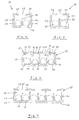
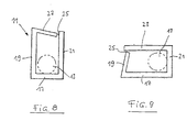
- Fig. 8 shows a front view of a line receiving channel 11 in which the entire ceiling area 23 is cantilevered. There is one Longitudinal separation 25 between the free end of the ceiling area 23 and the adjacent side wall 21 is formed.
- Fig. 9 shows a front view of an embodiment in which a Sidewall 19 is formed projecting, with a longitudinal separation 25 between the upper end of this side wall 19 and the ceiling area 23 is formed.
- the side wall is 19th resiliently designed towards the inside of the channel. Therefore a Round cable 13 by resiliently pushing in the side wall 19 are pressed into the interior of the channel.
- FIG. 10 to 12 is an embodiment of a line routing arrangement with hold-down bars in a smatic way.
- the Cross-sectional view in Fig. 12 shows a conduit duct open at the top 39 with side walls 41 and 43.
- a short distance above the cross brackets 53 are the two hold-down strips 37, from the inside of each of the two side walls 41 and 43 in the Protrude into the interior of the cable duct 39.
- this is from the loop area 55 remote end of the lower run 57 with the upper end of one fixed footplate 59 connected. That from loop area 55 the free end of the upper run 61 is located with an upstanding, movable head plate 63 serving as a spacer connected.
- the foot plate 59 is fixed with a not shown Facility connected.
- the head plate 63 is not shown reciprocating device connected.
- the head plate 63 moves between two end regions, which are shown in Figs. 10 and 11.
- the hold-down bars 37 are between the position of the fixed foot plate 59 and the in Fig. 11 shown left end position of the head plate 63, in which the Bottom run 57 is shortest.
- the hold down bars 37 are on this area of the trajectory of the movable head plate 63 limited to not on the one hand with the loop area 55 of the Line arrangement 47 to collide and because on the other hand faults and humps due to rapid head plate movement 63 occur only without the hold-down bars 37 when a particularly long upper run 61 is pushed from the top plate 63 becomes.
- the head plate 63 is at the embodiment shown in Fig. 12 on both sides with a recess 65 provided, in each of which one of the two hold-down strips 37 can protrude without movement disruption.
- FIG. 13 and 14 show a schematic side view of a Cable routing arrangement, in the loop area a roll 67 loose is arranged.
- the loop area 55 of the line arrangement 47 rolls on the circumference of the roller 67 when a movable device 69 moved horizontally back and forth relative to a fixed device 71 becomes. This leads to a shift of the loop area 55, which is followed by the roller 67.
- roller-like structures either solid or hollow, spherical structures and polygonal structures.
Landscapes
- General Engineering & Computer Science (AREA)
- Engineering & Computer Science (AREA)
- Mechanical Engineering (AREA)
- Electric Cable Arrangement Between Relatively Moving Parts (AREA)
- Details Of Indoor Wiring (AREA)
- Supports For Pipes And Cables (AREA)
- Laying Of Electric Cables Or Lines Outside (AREA)
- Electric Cable Installation (AREA)
- Input Circuits Of Receivers And Coupling Of Receivers And Audio Equipment (AREA)
- Vehicle Body Suspensions (AREA)
- Separation By Low-Temperature Treatments (AREA)
- Insulated Conductors (AREA)
- Superconductors And Manufacturing Methods Therefor (AREA)
- Revetment (AREA)
- Pens And Brushes (AREA)
Description
- Fig. 1
- eine perspektivische Darstellung einer erfindungsgemäßen Leitungsführungsanordnung mit einem einzigen Leitungsaufnahmekanal in perspektivischer Darstellung;
- Fig. 2
- eine Stirnseitenansicht der in Fig. 1 gezeigten Leitungsführungsanordnung;
- Fig. 3
- eine Stirnansicht einer gegenüber Fig. 1 modifizierten Leitungsführungsanordnung;
- Fig. 4
- eine Stirnansicht der in den Fig. 1 und 2 gezeigten Ausführungsform, jedoch mit einer Trennwand innerhalb des Leitungsaufnahmekanals;
- Fig. 5
- eine Stirnansicht einer Ausführungsform gemäß Fig. 3, jedoch mit einer Trennwand in dem Leitungsaufnahmekanal;
- Fig. 6
- eine Stirnansicht einer Leitungsführungsanordnung mit vier Leitungsaufnahmekanälen;
- Fig. 7
- eine Stirnansicht einer Leitungsführungsanordnung mit drei Leitungsaufnahmekanälen, die je mit einer Trennwand versehen sind;
- Fig. 8
- eine Ausführungsform eines Leitungsaufnahmekanals, bei dem eine Längstrennung zwischen einem Seitenende des Deckenbereichs und der benachbarten Seitenwand vorgesehen ist;
- Fig. 9
- eine Ausführungsform, bei welcher eine Längstrennung am oberen Ende einer Seitenwand vorgesehen ist;
- Fig. 10
- eine Ausführungsform, wie sie in Fig. 1 gezeigt ist, jedoch mit modifizierten Quertrennungen;
- Fig. 10 und 11
- in schematisierter Seitenansicht eine Leitungsführungsanordnung mit Niederhalteeinrichtung, wobei in den Fig. 10 und 11 entgegengesetzte Endpositionen der beweglichen Einrichtung dargestellt sind;
- Fig. 12
- eine Querschnittsdarstellung einer Leitungsführungsanordnung mit einer Niederhalteeinrichtung gem. Fig. 10 und 11; und
- Fig. 13 und 14
- in schematischer Seitendarstellung eine Leitungsführungsanordnung mit einer im Schleifenbereich angeordneten Rolle.
Claims (16)
- Leitungsführungsanordnung mit mindestens einem einen Bodenbereich (17), einen Deckenbereich (23) und Seitenwandbereiche (19, 21) aufweisenden Leitungsaufnahmekanal (11) für mindestens eine lose darin angeordnete ein- oder mehradrige Leitung (13, 15), wobei:der Leitungsaufnahmekanal unter Bildung eines ersten Trums und eines parallel dazu geführten zweiten Trums sowie eines schleifenartigen Übergangs zwischen den beiden Trums umbiegbar ist;der Bodenbereich (17) des Leitungsaufnahmekanals (11), mit dem das erste Trum und das zweite Trum zueinander weisen, mit Material guter Aneinandergleitfähigkeit aufgebaut ist;die Leitungsaufnahmekanalenden mit einer feststehenden bzw. mit einer in Längsrichtung des Leitungsaufnahmekanals (11) hin- und herbeweglichen Einrichtung verbindbar sind;der Leitungsaufnahmekanal (11) mit einer Vielzahl in Kanallängsrichtung im Abstand voneinander auftretender Quertrennungen (31) versehen ist, die sich durch den Deckenbereich (23) hindurch erstrecken und sich in die Seitenwandbereiche (19, 21, 33) mindestens bis in die Nähe des Bodenbereichs (17) fortsetzen und dem Leitungsaufnahmekanal (11) die Schleifenbildung zwischen erstem und zweiten Trum ermöglichen;und von dem Deckenbereich (23) und den Seitenwandbereichen (19, 21) des bzw. eines jeden Leitungsaufnahmekanals (11) mindestens einer (z. B. 23) dieser Bereiche vorkragend ausgebildet und relativ zu einem ihn tragenden Kanalwandbereich (19, 21) zum Kanalinneren hin federnd nachgiebig ist, derart, daß die mindestens eine Leitung (13, 15) von der Außenseite des Leitungsaufnahmekanals (11) aus durch den federnd nachgiebigen Bereich (27, 29) hindurch in das Innere des Leitungsaufnahmekanals (11) hineindrückbar ist und nach dem Rückfedern des federnd nachgiebigen Bereichs (27, 29) im Leitungsaufnahmekanal (11) eingeschlossen ist;und wobei die Quertrennungen (31) durch Quernuten mit sich verbreiternden Nutgründen (32) gebildet sind.
- Leitungsführungsanordnung nach Anspruch 1,
dadurch gekennzeichnet,
daß sich die Nutgründe (32) T-förmig verbreitern. - Leitungsführungsanordnung nach Anspruch 1 oder 2,
dadurch gekennzeichnet,
daß der Leitungsaufnahmekanal (11) im wesentlichen Rechteckquerschnitt aufweist und zwei Seitenwände (19, 21) und eine Decke (23) besitzt und daß die Decke (23) eine Längstrennung (25) aufweist, derart, daß sie mindestens einen sich von einer der Seitenwände (19, 21) aus vorkragenden Federbereich (27, 29) aufweist. - Leitungsführungsanordnung nach Anspruch 3,
dadurch gekennzeichnet,
daß die Längstrennung (25) etwa in der Deckenmitte verläuft, so daß zwei federnd nachgiebige Deckenbereiche (27, 29) gebildet sind, die sich von je einer der beiden Seitenwände (19, 21) vorkragend aufeinanderzuerstrecken. - Leitungsführungsanordnung nach Anspruch 3,
dadurch gekennzeichnet,
daß die Längstrennung (25) am Übergang zwischen der Decke (23) und einer ersten der beiden Seitenwände (19, 21) verläuft und die Decke (23) sich von der anderen, zweiten Seitenwand (19, 21) aus vorkragend zu der ersten Seitenwand (19, 21) hin erstreckt. - Leitungsführungsanordnung nach Anspruch 5,
dadurch gekennzeichnet,
daß die erste Seitenwand (19, 21) anstelle der Decke (23) oder zusätzlich zu dieser zum Kanalinneren hin federnd nachgiebig ist. - Leitungsführungsanordnung nach Anspruch 5 oder 6
dadurch gekennzeichnet,
daß die Decke (23) und im Fall der Ausbildung nach Anspruch 5 die Decke (23) und/oder die erste Seitenwand (19, 21) durch die Quertrennungen (31) in einzelne Federlaschen unterteilt ist bzw. sind. - Leitungsführungsanordnung nach Anspruch 1,
dadurch gekennzeichnet,daß der Leitungsaufnahmekanal mit einem Kanalboden und mit von dessen beiden Längsseiten hochstehenden, in Kanallängserstreckung im wesentlichen periodisch voneinander beabstandeten, Seitenwand- und Deckenfunktion des Leitungsaufnahmekanals aufweisenden Winkelelementen gebildet ist,daß die Winkelelemente je einen Seitenwandbereich und einen Deckenbereich, der eine in dem Leitungsaufnahmekanal angeordnete Leitung teilweise übergreift, aufweisen,und daß mindestens die Deckenbereiche der Winkelelemente zum Kanalboden hin federnd nachgiebig sind, derart, daß die Leitung von der Außenseite des Leitungsaufnahmekanals aus durch die federnd nachgiebigen Deckenbereiche der Winkelelemente hindurch in das Innere des Leitungsaufnahmekanals hineindrückbar ist und nach dem Rückfedern der federnd nachgiebigen Deckenbereiche im Leitungsaufnahmekanal eingeschlossen ist. - Leitungsführungsanordnung nach einem der Ansprüche 1 bis 8,
dadurch gekennzeichnet,
daß zur Bildung einer Leitungseinführhilfe der bzw. jeder vorkragend ausgebildete, federnd nachgiebige Bereich (27, 29) mit seinem freien Ende zum Inneren des Leitungsaufnahmekanals (11) hin geneigt ist. - Leitungsführungsanordnung nach einem der Ansprüche 1 bis 9,
dadurch gekennzeichnet,daß die beiden Trums ein Untertrum (57) und ein darüber führbares Obertrum (61) bildenund daß der Leitungsaufnahmekanal (11) in einem Leitungsführungskanal (39) geführt ist, in dem eine Niederhalteeinrichtung angeordnet ist, welche das Obertrum (61) in dem Bereich zwischen dem feststehenden Leitungsaufnahmekanalende und derjenigen Endstellung des beweglichen Leitungsaufnahmekanalendes, in welcher das Untertrum (57) am kürzesten ist, am Kanalboden (45) des Leitungsführungskanals (39) niederhält. - Leitungsführungsanordnung nach Anspruch 10,
dadurch gekennzeichnet,daß die Niederhalteeinrichtung durch zwei Niederhalteleisten (37) gebildet ist, die sich in Längsrichtung des Leitungsführungskanals (39) in etwa über den Bereich zwischen dem feststehenden Leitungsanordnungsende und derjenigen Endstellung des beweglichen Leitungsanordnungsendes in welcher das Untertrum (57) am kürzesten ist, erstrecken, die von je einer der beiden einander gegenüberliegenden Seitenwände (41, 43) des Leitungsführungskanals (39) in Richtung aufeinanderzu abstehenund die in einem lichten Abstand vom Kanalboden (45) verlaufen, der etwas größer ist als die horizontale Dicke der Leitungsanordnung (47). - Leitungsführungsanordnung nach Anspruch 11,
wobei das Obertrumende über einen in den Leitungsführungskanal (39) hineinragenden Abstandshalter mit der sich oberhalb des Leitungsführungskanals (39) bewegenden beweglichen Einrichtung verbunden ist,
dadurch gekennzeichnet,
daß zwischen den beiden Niederhalteleisten (37) ein derartiger lichter Abstand besteht, daß der Abstandshalter zwischen den beiden Niederhalteleisten (37) hindurchbewegbar ist. - Leitungsführungsanordnung nach einem der Ansprüche 1 bis 12,
dadurch gekennzeichnet,
daß der Schleifenbereich (55) der Leitungsanordnung (47) um eine mit dem Schleifenbereich (55) mitbewegliche Rolle (67) herumgeführt ist, auf welcher bei einer Bewegung der beweglichen Einrichtung (69) die Leitungsanordnung (47) abrollt. - Leitungsführungsanordnung nach Anspruch 13,
dadurch gekennzeichnet,
daß die Rolle (67) einen Durchmesser aufweist, der größer ist als der Schleifendurchmesser des Schleifenbereichs (55) bei nicht vorhandener Rolle (67). - Leitungsführungsanordnung nach Anspruch 13 oder 14,
dadurch gekennzeichnet,
daß die Rolle (67) lose in dem Schleifenbereich (55) angeordnet ist. - Leitungsführungsanordnung nach einem der Ansprüche 13 bis 15,
dadurch gekennzeichnet,
daß der Rollenumfang mit einem Material wie Gummi oder Weichkunststoff aufgebaut ist, der im Zusammenwirken mit dem Material guter Aneinandergleitfähigkeit der Leitungsanordnung (47) eine hohe Reibungskraft bewirkt.
Priority Applications (1)
| Application Number | Priority Date | Filing Date | Title |
|---|---|---|---|
| EP96101531A EP0724101B1 (de) | 1991-11-26 | 1991-11-26 | Leitungsführungsanordnung mit Nutgrundverbreiterung |
Applications Claiming Priority (2)
| Application Number | Priority Date | Filing Date | Title |
|---|---|---|---|
| EP96101531A EP0724101B1 (de) | 1991-11-26 | 1991-11-26 | Leitungsführungsanordnung mit Nutgrundverbreiterung |
| EP91120167A EP0544027B1 (de) | 1991-11-26 | 1991-11-26 | Schleppkettenersatz |
Related Parent Applications (2)
| Application Number | Title | Priority Date | Filing Date |
|---|---|---|---|
| EP91120167A Division EP0544027B1 (de) | 1991-11-26 | 1991-11-26 | Schleppkettenersatz |
| EP91120167.1 Division | 1991-11-26 |
Publications (2)
| Publication Number | Publication Date |
|---|---|
| EP0724101A1 EP0724101A1 (de) | 1996-07-31 |
| EP0724101B1 true EP0724101B1 (de) | 2000-02-02 |
Family
ID=8207379
Family Applications (5)
| Application Number | Title | Priority Date | Filing Date |
|---|---|---|---|
| EP91120167A Expired - Lifetime EP0544027B1 (de) | 1991-11-26 | 1991-11-26 | Schleppkettenersatz |
| EP96101532A Expired - Lifetime EP0724102B1 (de) | 1991-11-26 | 1991-11-26 | Leitungsführungsanordnung |
| EP96101531A Expired - Lifetime EP0724101B1 (de) | 1991-11-26 | 1991-11-26 | Leitungsführungsanordnung mit Nutgrundverbreiterung |
| EP92108881A Expired - Lifetime EP0544051B1 (de) | 1991-11-26 | 1992-05-26 | Schleppkettenersatz |
| EP95107663A Expired - Lifetime EP0670619B1 (de) | 1991-11-26 | 1992-05-26 | Schleppkettenersatz |
Family Applications Before (2)
| Application Number | Title | Priority Date | Filing Date |
|---|---|---|---|
| EP91120167A Expired - Lifetime EP0544027B1 (de) | 1991-11-26 | 1991-11-26 | Schleppkettenersatz |
| EP96101532A Expired - Lifetime EP0724102B1 (de) | 1991-11-26 | 1991-11-26 | Leitungsführungsanordnung |
Family Applications After (2)
| Application Number | Title | Priority Date | Filing Date |
|---|---|---|---|
| EP92108881A Expired - Lifetime EP0544051B1 (de) | 1991-11-26 | 1992-05-26 | Schleppkettenersatz |
| EP95107663A Expired - Lifetime EP0670619B1 (de) | 1991-11-26 | 1992-05-26 | Schleppkettenersatz |
Country Status (6)
| Country | Link |
|---|---|
| US (2) | US5322480A (de) |
| EP (5) | EP0544027B1 (de) |
| JP (3) | JP2726780B2 (de) |
| AT (4) | ATE189507T1 (de) |
| DE (4) | DE59108590D1 (de) |
| ES (1) | ES2145334T3 (de) |
Cited By (2)
| Publication number | Priority date | Publication date | Assignee | Title |
|---|---|---|---|---|
| DE102015200312A1 (de) | 2015-01-13 | 2016-07-14 | BSH Hausgeräte GmbH | Flexible Kabelaufnahmevorrichtung und diese enthaltendes Hausgerät |
| CN109560516A (zh) * | 2018-11-16 | 2019-04-02 | 合肥智瑞工程科技有限公司 | 一种用于线缆的拆装式固定安装槽及其使用方法 |
Families Citing this family (75)
| Publication number | Priority date | Publication date | Assignee | Title |
|---|---|---|---|---|
| DE10224858B4 (de) * | 2002-06-05 | 2005-07-14 | Kuka Roboter Gmbh | Vorrichtung zum Führen eines Schlauches |
| DE9016870U1 (de) | 1990-12-13 | 1992-04-16 | W.L. Gore & Associates Gmbh, 8011 Putzbrunn, De | |
| ATE189507T1 (de) * | 1991-11-26 | 2000-02-15 | Kabelschlepp Gmbh | Leitungsführungsanordnung mit nutgrundverbreiterung |
| IL111332A0 (en) * | 1993-10-20 | 1994-12-29 | Lasermaster Corp | Ink supply line support system for an ink jet printer |
| DE19512088C2 (de) * | 1995-04-03 | 1997-05-07 | Igus Gmbh | Energiekette |
| US5715761A (en) * | 1995-08-01 | 1998-02-10 | Knoll, Inc. | Article of furniture including a leg having wire management capabilities |
| GB9517027D0 (en) * | 1995-08-19 | 1995-10-25 | Orcina Cable Protection Limite | Bend limiter |
| US5836148A (en) * | 1996-02-06 | 1998-11-17 | Kunimorikagaku Ltd. | Cable chain |
| DE19710489A1 (de) | 1997-03-13 | 1998-09-24 | Kabelschlepp Gmbh | Faltbares Schutzelement für Leitungen |
| DE19817607A1 (de) * | 1998-04-17 | 1999-10-21 | Kuka Roboter Gmbh | Roboterarm |
| DE19837231A1 (de) * | 1998-08-17 | 2000-02-24 | Kabelschlepp Gmbh | Leitungsführungsanordnung |
| DE19839575A1 (de) | 1998-08-31 | 2000-03-09 | Kabelschlepp Gmbh | Energieführungskette zum Führen von Leitungen mit räumlich beweglichen Kettengliedern |
| DE19839966A1 (de) * | 1998-09-02 | 2000-04-06 | Kabelschlepp Gmbh | Leitungsführungsanordnung zum Führen wenigstens einer Leitung |
| DE19860948C2 (de) * | 1998-12-31 | 2002-02-14 | Igus Gmbh | Leitungsführungseinrichtung |
| AUPQ055099A0 (en) * | 1999-05-25 | 1999-06-17 | Pupbest Pty Ltd | Insertion tool |
| DE19962829A1 (de) | 1999-12-23 | 2001-08-23 | Kabelschlepp Gmbh | Strang und Verfahren zur Herstellung eines faserverstärkten Stranges einer Leitungsführungsanordnung |
| DE20002820U1 (de) | 2000-02-16 | 2000-05-25 | Igus Gmbh | Energieführungskette |
| FR2807229B1 (fr) * | 2000-03-28 | 2002-06-28 | Peugeot Citroen Automobiles Sa | Dispositif de support et de guidage d'un faisceau de fils electriquement conducteurs permettant de suivre les deplacements d'un siege avant de vehicule automobile |
| DE10218121B3 (de) * | 2002-04-23 | 2004-01-08 | Siemens Ag | Einrichtung zum Führen von Leitungen zwischen zwei zueinander beweglichen Teilen |
| JP4147896B2 (ja) * | 2002-10-28 | 2008-09-10 | 住友電装株式会社 | ケーブル配索構造 |
| US6858797B2 (en) * | 2002-11-22 | 2005-02-22 | Gore Enterprise Holdings, Inc. | Support member for an assembly |
| DE10306860B4 (de) * | 2003-02-19 | 2008-02-07 | Ekd Gelenkrohr Gmbh | Kettenglied für eine Energieführungskette |
| FR2851812B1 (fr) * | 2003-02-27 | 2006-08-11 | France Telecom | Dispositif de securisation de raccordement de micro tubes entre eux. |
| WO2004095666A1 (en) * | 2003-04-23 | 2004-11-04 | Novarix Ltd. | A device for supporting and stabilising a tubing, a wire and/or a light wave guide |
| DE10346486B4 (de) * | 2003-10-02 | 2012-08-02 | Murrplastik Systemtechnik Gmbh | Energieführungskette |
| US7718894B2 (en) * | 2003-10-15 | 2010-05-18 | Igus Gmbh | Line guide device |
| DE10352461B4 (de) * | 2003-11-07 | 2012-12-06 | Murrplastik Systemtechnik Gmbh | Vorrichtung zur Führung mindestens einer Leitung |
| US7784259B2 (en) * | 2004-01-23 | 2010-08-31 | A&A Manufacturing Co., Inc. | Monolithic enclosed cable carrier |
| US7049521B2 (en) * | 2004-03-30 | 2006-05-23 | Panduit Corp. | Flexible wiring duct |
| DE102004040162B4 (de) | 2004-08-19 | 2013-10-24 | Eisenmann Ag | Vorrichtung zum Beschichten von Gegenständen |
| JP4564866B2 (ja) * | 2005-03-04 | 2010-10-20 | 株式会社ディスコ | 伝達線固定具 |
| DE202005016472U1 (de) * | 2005-10-19 | 2006-01-19 | CCS Technology, Inc., Wilmington | Führungseinrichtung für Datenleiter sowie Verteilereinrichtung für Datenleiter eines Nachrichtenkabelkabels |
| JP5052073B2 (ja) * | 2006-09-04 | 2012-10-17 | 株式会社椿本チエイン | ケーブル類保護案内装置 |
| JP4350735B2 (ja) | 2006-09-20 | 2009-10-21 | 株式会社椿本チエイン | 折り曲げ式ケーブル類保護案内装置 |
| FR2909512A3 (fr) * | 2006-11-30 | 2008-06-06 | Renault Sas | F spositif articule pour le guidage de conducteurs, notamment de conducteurs electriques |
| JP4391547B2 (ja) * | 2007-04-17 | 2009-12-24 | 株式会社椿本チエイン | チューブ型ケーブル類保護案内装置 |
| DE102007041663A1 (de) | 2007-09-03 | 2009-03-05 | Kabelschlepp Gmbh | Einrichtung zum Führen von Leitungen, Schläuchen oder dergleichen |
| JP5356892B2 (ja) * | 2009-04-06 | 2013-12-04 | 矢崎総業株式会社 | ハーネス外装部材 |
| DE102009020016A1 (de) | 2009-05-05 | 2010-11-11 | Magna Car Top Systems Gmbh | Leitungsverlegungssystem für ein Faltverdeck |
| US8020813B1 (en) * | 2009-07-24 | 2011-09-20 | Cisco Technology, Inc. | Apparatus for routing cable across housing |
| CN101633174B (zh) * | 2009-08-03 | 2011-03-30 | 清华大学 | 冗余机器人布线防缠绕和挤压装置 |
| WO2011017225A2 (en) * | 2009-08-06 | 2011-02-10 | 3M Innovative Properties Company | System and method for providing final drop in a living unit in a building |
| KR20120112728A (ko) * | 2010-01-29 | 2012-10-11 | 우베-니토 카세이 가부시키가이샤 | 케이블 가이드 |
| JP5405401B2 (ja) * | 2010-07-15 | 2014-02-05 | 宇部エクシモ株式会社 | ケーブルガイド |
| JP5393508B2 (ja) * | 2010-01-29 | 2014-01-22 | 宇部エクシモ株式会社 | ケーブルガイド |
| JP2012039845A (ja) * | 2010-07-14 | 2012-02-23 | Ube Nitto Kasei Co Ltd | ケーブルガイド |
| JP2013013183A (ja) * | 2011-06-28 | 2013-01-17 | Sumitomo Wiring Syst Ltd | 電線保護具 |
| JP2013055737A (ja) * | 2011-09-01 | 2013-03-21 | Hitachi High-Technologies Corp | ケーブルガイド |
| JP5913883B2 (ja) * | 2011-09-26 | 2016-04-27 | 株式会社デンソーウェーブ | ケーブル保護案内部材の取付構造 |
| JP2013070552A (ja) | 2011-09-26 | 2013-04-18 | Tsubakimoto Chain Co | 合成樹脂製のケーブル・配管類保護案内部材 |
| JP5628124B2 (ja) | 2011-09-26 | 2014-11-19 | 株式会社椿本チエイン | 合成樹脂製のケーブル・配管類保護案内部材 |
| JP5893310B2 (ja) * | 2011-09-26 | 2016-03-23 | 株式会社デンソーウェーブ | ケーブル保護案内部材の取付構造、及びその取付構造を備えるロボット |
| JP5491472B2 (ja) | 2011-09-26 | 2014-05-14 | 株式会社椿本チエイン | ケーブル・配管類保護案内部材用取り付けブラケット |
| DE202012000614U1 (de) | 2012-01-24 | 2012-04-17 | Igus Gmbh | Führungseinrichtung |
| JP5844650B2 (ja) * | 2012-02-02 | 2016-01-20 | 株式会社オートネットワーク技術研究所 | 電池配線モジュール |
| JP5709799B2 (ja) * | 2012-05-28 | 2015-04-30 | 株式会社椿本チエイン | ケーブル類保護案内部材 |
| US9265345B2 (en) * | 2013-03-15 | 2016-02-23 | Streater LLC | Gondola shelf wire routing tray |
| JP2014207732A (ja) * | 2013-04-10 | 2014-10-30 | 株式会社潤工社 | ケーブルとケーブル支持装置との組立体 |
| JP6104097B2 (ja) * | 2013-08-20 | 2017-03-29 | アズビル株式会社 | ケーブルホルダ |
| JP2013258907A (ja) * | 2013-09-05 | 2013-12-26 | Ube Exsymo Co Ltd | ケーブルガイド |
| DE102014013845A1 (de) * | 2013-11-12 | 2015-05-13 | Knopp Fördertechnik | Leitungsführungsvorrichtung |
| KR101724393B1 (ko) * | 2014-07-03 | 2017-04-10 | 주식회사 에스디 | 수평도선의 설치 및 분리가 용이한 지지부재 |
| JP2016101027A (ja) * | 2014-11-25 | 2016-05-30 | 住友電装株式会社 | ワイヤハーネスおよびプロテクタ |
| DE102014226334A1 (de) * | 2014-12-17 | 2016-06-23 | Leoni Kabel Holding Gmbh | Kabelführungsvorrichtung sowie Verfahren zur Herstellung einer solchen Kabelführungsvorrichtung |
| JP2016131423A (ja) * | 2015-01-13 | 2016-07-21 | 株式会社オートネットワーク技術研究所 | 電線保護部材、電線保護部材付ワイヤーハーネス及びスライド配線装置 |
| JP6394979B2 (ja) * | 2015-04-17 | 2018-09-26 | 株式会社オートネットワーク技術研究所 | 外装体及びワイヤーハーネス |
| CN109526236B (zh) * | 2016-08-11 | 2021-09-24 | 利萨·德雷克塞迈尔有限责任公司 | 电平面导体设备和电平面导体设备的制造方法 |
| US10128643B2 (en) * | 2016-10-13 | 2018-11-13 | Illinois Tool Works Inc. | Loom assembly providing improved electrical isolation |
| JP6743744B2 (ja) * | 2017-03-30 | 2020-08-19 | 株式会社オートネットワーク技術研究所 | 外装体及びワイヤーハーネス |
| CN110535432A (zh) * | 2018-05-24 | 2019-12-03 | 北京铂阳顶荣光伏科技有限公司 | 线缆收集装置、线缆引导装置及建筑构件 |
| US11319808B2 (en) * | 2018-10-12 | 2022-05-03 | Caterpillar Global Mining Equipment Llc | Hose retention system for drilling machine |
| CN111404108B (zh) * | 2020-03-11 | 2021-04-09 | 扬州曙光电缆股份有限公司 | 高端数控机床用特种柔性电缆 |
| US11742646B2 (en) * | 2020-06-18 | 2023-08-29 | Commscope Technologies Llc | Aerial segmented virtual conduit |
| EP4092851A1 (de) * | 2021-05-17 | 2022-11-23 | Signify Holding B.V. | Halter zum halten oder führen von elektrischer verkabelung |
| CN113258511B (zh) * | 2021-06-01 | 2022-08-02 | 北京汽车集团越野车有限公司 | 线束固定装置 |
Family Cites Families (43)
| Publication number | Priority date | Publication date | Assignee | Title |
|---|---|---|---|---|
| US622442A (en) * | 1899-04-04 | Revolving guard for cycle-chains | ||
| DE436373C (de) * | 1926-10-30 | Buckau Akt Ges Zu Magdeburg Ma | Schraegaufzug, besonders mit Treibscheibenantrieb | |
| CA712656A (en) * | 1965-06-29 | A. Moore James | Cable construction | |
| US686052A (en) * | 1901-08-09 | 1901-11-05 | Joseph Henry Golding | Casing or covering for conductors in buildings. |
| FR436373A (fr) * | 1911-06-27 | 1912-03-26 | Anilin Fabrikation Ag | Nouveaux colorants au soufre et procédé pour leur fabrication |
| CH361538A (de) * | 1957-07-29 | 1962-04-15 | Tourtellier S A R L Ets | Biegsame, als Laufschiene für Hängebahnen oder zur Aufnahme von Stromleitern für ortsveränderliche Entnahme elektrischen Stromes verwendbare Schiene |
| DE1907410U (de) * | 1964-10-19 | 1964-12-31 | Gewerkschaft Eisenbuette Westf | Abdeckhaube fuer bergestossseitig gefuehrte ketten. |
| US3473769A (en) * | 1967-01-06 | 1969-10-21 | Ibm | Retainer for flexible leads |
| US3515013A (en) * | 1968-08-05 | 1970-06-02 | Layne & Bowler Pump Co | Resilient chain protector |
| US3630325A (en) * | 1969-12-16 | 1971-12-28 | Insul 8 Corp | Support system for movable conductors |
| JPS5035268Y2 (de) * | 1971-05-31 | 1975-10-14 | ||
| JPS4819194U (de) * | 1971-07-12 | 1973-03-03 | ||
| US3752180A (en) * | 1972-07-24 | 1973-08-14 | Firestone Tire & Rubber Co | Reciprocating multiple conductor support |
| JPS50116096U (de) * | 1974-03-08 | 1975-09-22 | ||
| JPS52115898U (de) * | 1976-03-01 | 1977-09-02 | ||
| JPS5364296U (de) * | 1976-10-27 | 1978-05-30 | ||
| JPS5643696Y2 (de) * | 1977-03-23 | 1981-10-13 | ||
| DE2805832C3 (de) * | 1978-02-11 | 1981-02-05 | Kabelschlepp Gmbh, 5900 Siegen | Energieleitungsträger |
| US4266744A (en) * | 1979-04-16 | 1981-05-12 | Crown Controls Corporation | Cable and hose guide |
| JPS5856526U (ja) * | 1981-10-09 | 1983-04-16 | 攝陽工業株式会社 | 配線用線樋 |
| JPS5872923U (ja) * | 1981-11-06 | 1983-05-17 | 住友電装株式会社 | ワイヤ−ハ−ネス用プロテクタ |
| JPS5885040U (ja) * | 1981-12-03 | 1983-06-09 | 後藤 正 | 巾木取付装置 |
| SE8200148L (sv) * | 1982-01-13 | 1983-07-14 | Stiebel Sven Michael | Anordning vid en kedjekonstruktion med hallardon avsedda att uppbera och styra en eller flera flexibla energioverforande ledningar |
| JPS5958406U (ja) * | 1982-10-08 | 1984-04-16 | 株式会社朝倉製作所 | 通信線のコ−ナ−部布設用保持具 |
| DE3241924C2 (de) * | 1982-11-12 | 1986-09-25 | Schubert & Salzer Maschinenfabrik Ag, 8070 Ingolstadt | Vorrichtung zum Führen von flexiblen Versorgungsleitungen |
| SU1288769A1 (ru) * | 1983-08-10 | 1987-02-07 | Всесоюзный Проектно-Конструкторский Институт Сварочного Производства | Устройство подвода энергомагистралей к подвижному,преимущественно транспортному оборудованию и энергоподвод ща цепь |
| JPS6138987U (ja) * | 1984-08-09 | 1986-03-11 | パイオニア株式会社 | 電線結束固定部品 |
| JPS6181716U (de) * | 1984-10-31 | 1986-05-30 | ||
| JPH0331669Y2 (de) * | 1986-08-21 | 1991-07-04 | ||
| SU1534596A1 (ru) * | 1987-08-31 | 1990-01-07 | Предприятие П/Я А-1836 | Устройство дл подвода энергии от неподвижного объекта к подвижному |
| DD265449B5 (de) * | 1987-10-01 | 1996-11-28 | Kabelschlepp Gmbh | Kabel- und Schlauchschlepp |
| GB8801707D0 (en) * | 1988-01-26 | 1988-02-24 | Dunn W H & Son Ltd | Line protecting apparatus |
| JPH01157522U (de) * | 1988-04-13 | 1989-10-31 | ||
| DE8811440U1 (de) * | 1988-09-09 | 1988-11-10 | Murr-Plastik Gmbh, 7155 Oppenweiler, De | |
| FR2640599A1 (fr) * | 1988-12-16 | 1990-06-22 | Saurer Diederichs Sa | Dispositif d'entrainement d'un chariot et d'alimentation de celui-ci en fluide et/ou en vide et/ou en electricite depuis un point fixe |
| JPH02237417A (ja) * | 1989-03-08 | 1990-09-20 | Showa Electric Wire & Cable Co Ltd | U字運動ケーブルの保持機構 |
| DE4031235A1 (de) * | 1990-03-02 | 1991-09-12 | Thomas & Betts Corp | Verbindungsvorrichtung |
| IT1239969B (it) * | 1990-05-11 | 1993-11-27 | Magitex | Canalina per il supporto di una catena porta condutture e un apparato mobile per la pulizia di un impianto tessile |
| DE9016870U1 (de) * | 1990-12-13 | 1992-04-16 | W.L. Gore & Associates Gmbh, 8011 Putzbrunn, De | |
| US5149017A (en) * | 1991-11-15 | 1992-09-22 | Teledyne Inet | Service transport unit |
| ATE189507T1 (de) * | 1991-11-26 | 2000-02-15 | Kabelschlepp Gmbh | Leitungsführungsanordnung mit nutgrundverbreiterung |
| DE4140910C1 (de) * | 1991-12-12 | 1993-02-25 | Kabelschlepp Gmbh, 5900 Siegen, De | |
| US5332825A (en) * | 1993-10-13 | 1994-07-26 | Eastman Kodak Company | Single vessel synthesis of aminoacetonitriles |
-
1991
- 1991-11-26 AT AT96101531T patent/ATE189507T1/de not_active IP Right Cessation
- 1991-11-26 EP EP91120167A patent/EP0544027B1/de not_active Expired - Lifetime
- 1991-11-26 EP EP96101532A patent/EP0724102B1/de not_active Expired - Lifetime
- 1991-11-26 DE DE59108590T patent/DE59108590D1/de not_active Expired - Lifetime
- 1991-11-26 AT AT91120167T patent/ATE149656T1/de not_active IP Right Cessation
- 1991-11-26 DE DE59109182T patent/DE59109182D1/de not_active Expired - Fee Related
- 1991-11-26 ES ES96101531T patent/ES2145334T3/es not_active Expired - Lifetime
- 1991-11-26 EP EP96101531A patent/EP0724101B1/de not_active Expired - Lifetime
- 1991-12-10 US US07/805,685 patent/US5322480A/en not_active Expired - Lifetime
-
1992
- 1992-03-06 JP JP4935492A patent/JP2726780B2/ja not_active Expired - Fee Related
- 1992-05-26 EP EP92108881A patent/EP0544051B1/de not_active Expired - Lifetime
- 1992-05-26 EP EP95107663A patent/EP0670619B1/de not_active Expired - Lifetime
- 1992-05-26 DE DE59209912T patent/DE59209912D1/de not_active Expired - Fee Related
- 1992-05-26 AT AT95107663T patent/ATE203804T1/de not_active IP Right Cessation
- 1992-05-26 DE DE59205163T patent/DE59205163D1/de not_active Expired - Fee Related
- 1992-05-26 AT AT92108881T patent/ATE133484T1/de not_active IP Right Cessation
-
1994
- 1994-06-09 US US08/257,660 patent/US5411443A/en not_active Expired - Lifetime
-
1996
- 1996-09-05 JP JP23555496A patent/JP3182086B2/ja not_active Expired - Fee Related
- 1996-09-05 JP JP23555396A patent/JP3182085B2/ja not_active Expired - Fee Related
Cited By (2)
| Publication number | Priority date | Publication date | Assignee | Title |
|---|---|---|---|---|
| DE102015200312A1 (de) | 2015-01-13 | 2016-07-14 | BSH Hausgeräte GmbH | Flexible Kabelaufnahmevorrichtung und diese enthaltendes Hausgerät |
| CN109560516A (zh) * | 2018-11-16 | 2019-04-02 | 合肥智瑞工程科技有限公司 | 一种用于线缆的拆装式固定安装槽及其使用方法 |
Also Published As
| Publication number | Publication date |
|---|---|
| EP0670619A3 (de) | 1996-06-05 |
| EP0670619B1 (de) | 2001-08-01 |
| EP0670619A2 (de) | 1995-09-06 |
| EP0544051B1 (de) | 1996-01-24 |
| EP0544051A1 (de) | 1993-06-02 |
| JPH09154214A (ja) | 1997-06-10 |
| JPH09154213A (ja) | 1997-06-10 |
| JPH05161232A (ja) | 1993-06-25 |
| ATE203804T1 (de) | 2001-08-15 |
| JP2726780B2 (ja) | 1998-03-11 |
| US5322480A (en) | 1994-06-21 |
| DE59205163D1 (de) | 1996-03-07 |
| DE59109182D1 (de) | 2000-03-09 |
| JP3182086B2 (ja) | 2001-07-03 |
| EP0544027A1 (de) | 1993-06-02 |
| ATE133484T1 (de) | 1996-02-15 |
| DE59209912D1 (de) | 2001-09-06 |
| EP0724101A1 (de) | 1996-07-31 |
| EP0724102A1 (de) | 1996-07-31 |
| JP3182085B2 (ja) | 2001-07-03 |
| EP0544027B1 (de) | 1997-03-05 |
| ATE189507T1 (de) | 2000-02-15 |
| US5411443A (en) | 1995-05-02 |
| EP0724102B1 (de) | 2000-02-02 |
| ES2145334T3 (es) | 2000-07-01 |
| DE59108590D1 (de) | 1997-04-10 |
| ATE149656T1 (de) | 1997-03-15 |
Similar Documents
| Publication | Publication Date | Title |
|---|---|---|
| EP0724101B1 (de) | Leitungsführungsanordnung mit Nutgrundverbreiterung | |
| EP0490022B1 (de) | Leitungsführungsanordnung | |
| EP1104589B1 (de) | Leitungsführungsanordnung | |
| EP1869744B1 (de) | Leitungsführungseinrichtung und system bestehend aus einer leitungsführungseinrichtung und einer diese aufnehmenden haltevorrichtung | |
| DE2112573C3 (de) | Stabrost, beispielsweise zur begehbaren abdeckung von rinnen oder dergleichen | |
| EP2333195B1 (de) | Fußboden, erstellt aus Fußbodenpaneelen mit separaten Verbindungsmitteln | |
| EP0750378A1 (de) | Schlauchförmiger Umhüllungskanal zur Ummantelung von Kabelbündel | |
| EP2628696A1 (de) | Walze zum Führen einer Flachbahn | |
| DE19641421C2 (de) | Wellrohr zur schützenden Ummantelung elektrischer Leitungen | |
| EP0287148B1 (de) | Kabelführungsanordnung | |
| EP0300022A1 (de) | Ausziehführung. | |
| EP2026437A1 (de) | Energieführungskettenanordnung | |
| WO1988007281A1 (en) | Device for fitting additional cables into protective cable pipes | |
| DE3212042A1 (de) | Regal- und ausstellungskonstruktion | |
| EP2202175A1 (de) | Kabelbinder | |
| DE1962889C3 (de) | Wand- oder Deckenbekleidung mit Lamellen | |
| WO1991003195A1 (de) | Trägerplatte zum aufhängen von werkzeugen, behältern, geräten und dgl. | |
| EP2388485B1 (de) | Führungsschienensegment | |
| DE19531658B4 (de) | Stützvorrichtung für eine Kabelbahn | |
| EP0590470A1 (de) | Sortier- und Abstellpalette für Einzelglasscheiben | |
| DE3814734A1 (de) | Profilschiene | |
| DE202019101817U1 (de) | Verbindereinheit für eine Führungsrinne einer Energieführungskette | |
| DE102022112248A1 (de) | Steckverbinder | |
| DE3306920C1 (de) | Vorrichtung zum Aufhängen von Gardinen oder dergleichen | |
| DE3000334A1 (de) | Vorrichtung fuer vorhangaufhaenger |
Legal Events
| Date | Code | Title | Description |
|---|---|---|---|
| PUAI | Public reference made under article 153(3) epc to a published international application that has entered the european phase |
Free format text: ORIGINAL CODE: 0009012 |
|
| 17P | Request for examination filed |
Effective date: 19960202 |
|
| AC | Divisional application: reference to earlier application |
Ref document number: 544027 Country of ref document: EP |
|
| AK | Designated contracting states |
Kind code of ref document: A1 Designated state(s): AT CH DE ES FR GB IT LI NL SE |
|
| RAP1 | Party data changed (applicant data changed or rights of an application transferred) |
Owner name: KABELSCHLEPP GESELLSCHAFT MIT BESCHRAENKTER HAFTUN |
|
| 17Q | First examination report despatched |
Effective date: 19990121 |
|
| GRAG | Despatch of communication of intention to grant |
Free format text: ORIGINAL CODE: EPIDOS AGRA |
|
| GRAG | Despatch of communication of intention to grant |
Free format text: ORIGINAL CODE: EPIDOS AGRA |
|
| GRAH | Despatch of communication of intention to grant a patent |
Free format text: ORIGINAL CODE: EPIDOS IGRA |
|
| GRAH | Despatch of communication of intention to grant a patent |
Free format text: ORIGINAL CODE: EPIDOS IGRA |
|
| GRAA | (expected) grant |
Free format text: ORIGINAL CODE: 0009210 |
|
| AC | Divisional application: reference to earlier application |
Ref document number: 544027 Country of ref document: EP |
|
| AK | Designated contracting states |
Kind code of ref document: B1 Designated state(s): AT CH DE ES FR GB IT LI NL SE |
|
| PG25 | Lapsed in a contracting state [announced via postgrant information from national office to epo] |
Ref country code: NL Free format text: LAPSE BECAUSE OF FAILURE TO SUBMIT A TRANSLATION OF THE DESCRIPTION OR TO PAY THE FEE WITHIN THE PRESCRIBED TIME-LIMIT Effective date: 20000202 |
|
| REF | Corresponds to: |
Ref document number: 189507 Country of ref document: AT Date of ref document: 20000215 Kind code of ref document: T |
|
| REG | Reference to a national code |
Ref country code: CH Ref legal event code: EP |
|
| REF | Corresponds to: |
Ref document number: 59109182 Country of ref document: DE Date of ref document: 20000309 |
|
| ITF | It: translation for a ep patent filed |
Owner name: DE DOMINICIS & MAYER S.R.L. |
|
| PG25 | Lapsed in a contracting state [announced via postgrant information from national office to epo] |
Ref country code: SE Free format text: LAPSE BECAUSE OF FAILURE TO SUBMIT A TRANSLATION OF THE DESCRIPTION OR TO PAY THE FEE WITHIN THE PRESCRIBED TIME-LIMIT Effective date: 20000502 |
|
| GBT | Gb: translation of ep patent filed (gb section 77(6)(a)/1977) |
Effective date: 20000419 |
|
| ET | Fr: translation filed | ||
| REG | Reference to a national code |
Ref country code: ES Ref legal event code: FG2A Ref document number: 2145334 Country of ref document: ES Kind code of ref document: T3 |
|
| NLV1 | Nl: lapsed or annulled due to failure to fulfill the requirements of art. 29p and 29m of the patents act | ||
| PG25 | Lapsed in a contracting state [announced via postgrant information from national office to epo] |
Ref country code: AT Free format text: LAPSE BECAUSE OF NON-PAYMENT OF DUE FEES Effective date: 20001126 |
|
| PG25 | Lapsed in a contracting state [announced via postgrant information from national office to epo] |
Ref country code: LI Free format text: LAPSE BECAUSE OF NON-PAYMENT OF DUE FEES Effective date: 20001130 Ref country code: CH Free format text: LAPSE BECAUSE OF NON-PAYMENT OF DUE FEES Effective date: 20001130 |
|
| PLBE | No opposition filed within time limit |
Free format text: ORIGINAL CODE: 0009261 |
|
| STAA | Information on the status of an ep patent application or granted ep patent |
Free format text: STATUS: NO OPPOSITION FILED WITHIN TIME LIMIT |
|
| 26N | No opposition filed | ||
| REG | Reference to a national code |
Ref country code: CH Ref legal event code: PL |
|
| REG | Reference to a national code |
Ref country code: GB Ref legal event code: IF02 |
|
| PGFP | Annual fee paid to national office [announced via postgrant information from national office to epo] |
Ref country code: GB Payment date: 20031027 Year of fee payment: 13 |
|
| PGFP | Annual fee paid to national office [announced via postgrant information from national office to epo] |
Ref country code: ES Payment date: 20031110 Year of fee payment: 13 |
|
| PGFP | Annual fee paid to national office [announced via postgrant information from national office to epo] |
Ref country code: FR Payment date: 20031120 Year of fee payment: 13 |
|
| PG25 | Lapsed in a contracting state [announced via postgrant information from national office to epo] |
Ref country code: GB Free format text: LAPSE BECAUSE OF NON-PAYMENT OF DUE FEES Effective date: 20041126 |
|
| PG25 | Lapsed in a contracting state [announced via postgrant information from national office to epo] |
Ref country code: ES Free format text: LAPSE BECAUSE OF NON-PAYMENT OF DUE FEES Effective date: 20041127 |
|
| GBPC | Gb: european patent ceased through non-payment of renewal fee |
Effective date: 20041126 |
|
| PG25 | Lapsed in a contracting state [announced via postgrant information from national office to epo] |
Ref country code: FR Free format text: LAPSE BECAUSE OF NON-PAYMENT OF DUE FEES Effective date: 20050729 |
|
| REG | Reference to a national code |
Ref country code: FR Ref legal event code: ST |
|
| REG | Reference to a national code |
Ref country code: ES Ref legal event code: FD2A Effective date: 20041127 |
|
| PGFP | Annual fee paid to national office [announced via postgrant information from national office to epo] |
Ref country code: DE Payment date: 20081210 Year of fee payment: 18 |
|
| PGFP | Annual fee paid to national office [announced via postgrant information from national office to epo] |
Ref country code: IT Payment date: 20081120 Year of fee payment: 18 |
|
| PG25 | Lapsed in a contracting state [announced via postgrant information from national office to epo] |
Ref country code: DE Free format text: LAPSE BECAUSE OF NON-PAYMENT OF DUE FEES Effective date: 20100601 |
|
| PG25 | Lapsed in a contracting state [announced via postgrant information from national office to epo] |
Ref country code: IT Free format text: LAPSE BECAUSE OF NON-PAYMENT OF DUE FEES Effective date: 20091126 |