EP0646828B1 - Dispositif de visualisation par projection - Google Patents
Dispositif de visualisation par projection Download PDFInfo
- Publication number
- EP0646828B1 EP0646828B1 EP94910021A EP94910021A EP0646828B1 EP 0646828 B1 EP0646828 B1 EP 0646828B1 EP 94910021 A EP94910021 A EP 94910021A EP 94910021 A EP94910021 A EP 94910021A EP 0646828 B1 EP0646828 B1 EP 0646828B1
- Authority
- EP
- European Patent Office
- Prior art keywords
- color
- beams
- lens
- light
- illumination optical
- Prior art date
- Legal status (The legal status is an assumption and is not a legal conclusion. Google has not performed a legal analysis and makes no representation as to the accuracy of the status listed.)
- Expired - Lifetime
Links
Images


Classifications
-
- G—PHYSICS
- G02—OPTICS
- G02B—OPTICAL ELEMENTS, SYSTEMS OR APPARATUS
- G02B3/00—Simple or compound lenses
- G02B3/0006—Arrays
- G02B3/0037—Arrays characterized by the distribution or form of lenses
- G02B3/0043—Inhomogeneous or irregular arrays, e.g. varying shape, size, height
-
- G—PHYSICS
- G02—OPTICS
- G02B—OPTICAL ELEMENTS, SYSTEMS OR APPARATUS
- G02B3/00—Simple or compound lenses
- G02B3/0006—Arrays
- G02B3/0037—Arrays characterized by the distribution or form of lenses
- G02B3/005—Arrays characterized by the distribution or form of lenses arranged along a single direction only, e.g. lenticular sheets
-
- G—PHYSICS
- G02—OPTICS
- G02B—OPTICAL ELEMENTS, SYSTEMS OR APPARATUS
- G02B3/00—Simple or compound lenses
- G02B3/0006—Arrays
- G02B3/0037—Arrays characterized by the distribution or form of lenses
- G02B3/0056—Arrays characterized by the distribution or form of lenses arranged along two different directions in a plane, e.g. honeycomb arrangement of lenses
-
- G—PHYSICS
- G02—OPTICS
- G02B—OPTICAL ELEMENTS, SYSTEMS OR APPARATUS
- G02B3/00—Simple or compound lenses
- G02B3/0006—Arrays
- G02B3/0037—Arrays characterized by the distribution or form of lenses
- G02B3/0062—Stacked lens arrays, i.e. refractive surfaces arranged in at least two planes, without structurally separate optical elements in-between
-
- G—PHYSICS
- G03—PHOTOGRAPHY; CINEMATOGRAPHY; ANALOGOUS TECHNIQUES USING WAVES OTHER THAN OPTICAL WAVES; ELECTROGRAPHY; HOLOGRAPHY
- G03B—APPARATUS OR ARRANGEMENTS FOR TAKING PHOTOGRAPHS OR FOR PROJECTING OR VIEWING THEM; APPARATUS OR ARRANGEMENTS EMPLOYING ANALOGOUS TECHNIQUES USING WAVES OTHER THAN OPTICAL WAVES; ACCESSORIES THEREFOR
- G03B21/00—Projectors or projection-type viewers; Accessories therefor
- G03B21/14—Details
- G03B21/20—Lamp housings
- G03B21/208—Homogenising, shaping of the illumination light
-
- G—PHYSICS
- G03—PHOTOGRAPHY; CINEMATOGRAPHY; ANALOGOUS TECHNIQUES USING WAVES OTHER THAN OPTICAL WAVES; ELECTROGRAPHY; HOLOGRAPHY
- G03B—APPARATUS OR ARRANGEMENTS FOR TAKING PHOTOGRAPHS OR FOR PROJECTING OR VIEWING THEM; APPARATUS OR ARRANGEMENTS EMPLOYING ANALOGOUS TECHNIQUES USING WAVES OTHER THAN OPTICAL WAVES; ACCESSORIES THEREFOR
- G03B33/00—Colour photography, other than mere exposure or projection of a colour film
- G03B33/10—Simultaneous recording or projection
- G03B33/12—Simultaneous recording or projection using beam-splitting or beam-combining systems, e.g. dichroic mirrors
-
- H—ELECTRICITY
- H04—ELECTRIC COMMUNICATION TECHNIQUE
- H04N—PICTORIAL COMMUNICATION, e.g. TELEVISION
- H04N9/00—Details of colour television systems
- H04N9/12—Picture reproducers
- H04N9/31—Projection devices for colour picture display, e.g. using electronic spatial light modulators [ESLM]
- H04N9/3102—Projection devices for colour picture display, e.g. using electronic spatial light modulators [ESLM] using two-dimensional electronic spatial light modulators
- H04N9/3105—Projection devices for colour picture display, e.g. using electronic spatial light modulators [ESLM] using two-dimensional electronic spatial light modulators for displaying all colours simultaneously, e.g. by using two or more electronic spatial light modulators
-
- H—ELECTRICITY
- H04—ELECTRIC COMMUNICATION TECHNIQUE
- H04N—PICTORIAL COMMUNICATION, e.g. TELEVISION
- H04N9/00—Details of colour television systems
- H04N9/12—Picture reproducers
- H04N9/31—Projection devices for colour picture display, e.g. using electronic spatial light modulators [ESLM]
- H04N9/3141—Constructional details thereof
- H04N9/315—Modulator illumination systems
- H04N9/3167—Modulator illumination systems for polarizing the light beam
-
- H—ELECTRICITY
- H04—ELECTRIC COMMUNICATION TECHNIQUE
- H04N—PICTORIAL COMMUNICATION, e.g. TELEVISION
- H04N5/00—Details of television systems
- H04N5/74—Projection arrangements for image reproduction, e.g. using eidophor
- H04N5/7416—Projection arrangements for image reproduction, e.g. using eidophor involving the use of a spatial light modulator, e.g. a light valve, controlled by a video signal
- H04N5/7441—Projection arrangements for image reproduction, e.g. using eidophor involving the use of a spatial light modulator, e.g. a light valve, controlled by a video signal the modulator being an array of liquid crystal cells
Definitions
- the present invention relates to a projection-type display apparatus which separates a white beam from a light source into beams of three colors, red, blue and green, modulates these beams through light valves according to image information, and re-synthesizes and projects the modulated beams under magnification onto a screen through a projection lens.
- a projection-type display apparatus is comprised of a light source lamp, a color separating means for separating a white beam from the light source lamp into beams of three colors, three light valves for modulating the separated color beams, a color synthesizing means for synthesizing the modulated beams again, and a projection lens for magnifying and displaying a light image obtained by the synthesis onto a screen.
- a light source lamp a color separating means for separating a white beam from the light source lamp into beams of three colors
- three light valves for modulating the separated color beams
- a color synthesizing means for synthesizing the modulated beams again
- a projection lens for magnifying and displaying a light image obtained by the synthesis onto a screen.
- light valves liquid crystal panels are generally used.
- a conventional projection-type display apparatus having such structure in which a uniform illumination optical device referred to as an optical integrator is incorporated in a light source thereof is well known.
- U. S. Patent No. 5,098,184 discloses a projection-type display apparatus having such optical integrator incorporated therein.
- This patent publication also discloses a color synthesizing means consisting of dichroic mirrors arranged in the shape of X.
- An ordinary color synthesizing means is constituted by dichroic mirrors each of which has a dielectric multilayer film on a glass plate.
- Such projection-type display apparatus provided with a mirror composite system in which a color synthesizing means is constituted by dichroic mirrors has the following disadvantage.
- Each dichroic mirror is an optical element which is rotationally asymmetrical about the center axis of a projection lens. Therefore, astigmatism arises in an image on the screen, and Modulation Transfer Function (MTF) representing the transfer characteristic of a projection optical system is lowered. As a result, the image is blurred and sharpness thereof is reduced.
- MTF Modulation Transfer Function
- the size of a liquid crystal panel is large relative to the number of pixels, in other words, when the pixel pitch is large, the lowering of the MTF does not cause such a large problem.
- the pixel pitch is small, for example, as in a liquid crystal panel using a polysilicon TFT as a switching device, such lowering cannot be ignored.
- a conventional projection-type display apparatus having a prism composite system in which a color synthesizing means consists of a dichroic prism is well known.
- the dichroic prism is an optical element which is rotationally symmetrical about the center axis of a projection lens. Therefore, astigmatism caused by this prism can be easily removed by the design of the projection lens, and the MTF of the projection-type display apparatus having such a prism composite system is generally superior to that of the above-mentioned display apparatus having the mirror composite system. Accordingly, such apparatus is suitable in the case in which a liquid crystal panel having a small pixel pitch is used as a light valve.
- the brightness distribution thereof is made to do a complete about-face by the relay lens. Therefore, if the initial brightness distribution is not axially symmetrical, color unevenness arises in the display on a screen, and the quality of the display is degraded. Though such color unevenness does not arise if the brightness distribution of the beam is axially symmetrical, in fact, the brightness distribution is normally made axially asymmetrical by the displacement of an attachment position of a light source lamp and the slight asymmetrical properties of the light source lamp and a reflecting mirror.
- a projection-type display apparatus it is desirable to increase the luminous intensity of an image to be projected, and to obtain an image quality close to that of the image directly viewed on a CRT without unevenness in color and luminous intensity.
- a prism composite system having a good transfer characteristic as a color synthesizing system. It is also preferable to efficiently illuminate a liquid crystal panel with uniform brightness by using an optical integrator in a light source portion.
- the optical integrator is used as it is in a case in which the optical path lengths of the beams in the color separating system are different, the decrease in the amount of light and change of brightness distribution of the beam having the longest optical path are remarkable, which results in color unevenness and a change in color temperature of a projected image. Therefore, a sufficient effect of the integrator cannot be shown. Furthermore, when the optical integrator is used in the light source portion, the conventional art cannot be utilized as it is.
- the illumination with the optical integrator is basically different from the illumination from a point light source existing at an infinite distance from the liquid crystal panel as in the arrangement of the conventional art.
- An object of the present invention is to provide a projector which can generate a projection image of higher quality, compared with the above-mentioned conventional projector, without any unevenness in luminous intensity and color.
- Another object of the present invention is to provide an inexpensive projector which can generate a projection image of high quality.
- Still another object of the present invention is to provide a projector which can generate a projection image having higher luminous intensity than a conventional one.
- a further object of the present invention is to provide a compact projector which can generate a projection image of high quality.
- a still further object of the present invention is to provide a projector suited to be used for front projection.
- EP-A-0 512 893 does not disclose "three condenser lenses", “triangular prims” and a “light guide member”, as expressly recited in the characterising portion of Claim 1, but discloses all the other features of Claim 1.
- JP-A-62-237485 does not disclose a "uniform illumination optical means” and "three condenser lenses", as in Claim 1. Instead; it uses three light guide members which are located in three outputting portions of color separating means.
- the present invention provides a projector comprising a light source, color separating means for separating a light beam emitted from said light source into beams of three colors, three light valves for modulating said separated color beams, a uniform illumination optical means interposed on an optical path between said light source and said color separating means so as to convert said light beam from said light source into a plurality of rectangular beams and to output each of said rectangular beams towards said color separating means, light guide means located on an optical path of one color beam having the longest optical path length among said color beams separated by said color separating means and respectively incident on said three light valves, color synthesizing means for synthesizing said color beams modulated through said light valves, and a projection lens for projecting said synthesized and modulated beam onto a screen, characterised in that, three condenser lenses are located respectively in outputting portions of said color separating means for outputting said color light beams to convert said beams output from said uniform illumination optical means into almost collimated beams,
- the light valves are illuminated by the uniform illumination means, the diverged color beams are collimated by the condenser lenses respectively located on the optical paths of the color beams, and the effects of differences in the optical path lengths of the color beams are corrected by making one color beam, which has the longest optical path length among the color beams, pass through the light guide system. Therefore, according to the present invention, it is possible to form a projection image with uniform illumination distribution and little color unevenness, and more brightness and higher quality than ever.
- the light guide means have one intermediate lens, and the focal length of the intermediate lens be set within a range of approximately 0.9 to 1.1 times of the optical path length of the light guide means.
- the light guide means may also comprise an incident side reflecting mirror, an emission side reflecting mirror, an incident lens located in the incident side of the incident side reflecting mirror, an output lens located on the output side of the output side reflecting mirror, and an intermediate lens located between the incident and output side reflecting mirrors.
- the focal lengths of the incident and output side lenses each be set between approximately 0.5 to 0.7 times of the optical path length of the light guide means and the focal length of the intermediate lens be set between approximately 0.25 and 0.4 times of the optical path length of the light guide means so as to restrict any aberration.
- the optical system can be made compact by combining the above incident lens and the above condenser lens for making the collimated beam incident on the incident lens into a single lens, and that is preferable.
- the single lens it is preferable that the lens be an aspherical lens in order to restrict aberration in the periphery thereof.
- Liquid crystal panels are available as the above-mentioned light valves. In this case, it is preferable that resolution of a projection image be enhanced by setting a pixel pitch of each liquid crystal panel at less than approximately 50 ⁇ m.
- the uniform illumination optical system may be provided with at least one lens plate consisting of a plurality of lenses arranged in a plane perpendicular to the chief axis of the light emitted from the light source lamp.
- the split number of the lens plate in one direction be set between approximately 3 to 7.
- a green light beam whose amount of light is normally larger than that of other color beams, or a blue light beam in which the influence on an image quality caused by change in the amount of light is relatively difficult to detect is preferable as a color beam to be passed through the above light guide means.
- the uniform illumination optical system may be constituted by a first lens plate, a second lens plate and a reflecting mirror interposed between the lens plates, and the optical path thereof may be folded, for example, at a right angle.
- a polarized beam conversion means be located between the light source lamp and the uniform illumination optical means.
- the polarized beam conversion means is constituted by a polarized beam separating element for separating a random polarized beam from the light source lamp into two linearly polarized beams of P and S beams, and a polarization plane rotating means for rotating a polarization plane of one of the two separated and polarized beams at an angle of 90° so as to coincide with that of the other linearly polarized beam. Since the use of the polarized beam conversion means makes it possible to enhance the use efficiency of light emitted from the light source lamp, the luminous intensity of a projection image can be increased.
- the light guide system is provided with an incident side triangular prism located on the incident side for folding an optical path at a right angle, an output side triangular prism located on the output side for folding the optical path at a right angle, and a light guide member located between these triangular prisms, it is possible to form a projection image with uniform illumination distribution and little color unevenness and having more brightness and higher quality than ever.
- a quadratic prism may be used as the light guide member. It is preferable that interfaces of the triangular prism and the quadratic prism be covered with an anti-reflective coating. Furthermore, it is preferable that a total reflection surface of each triangular prism be coated with a metal film or a dielectric multilayer film.
- the light guide means may be provided with an incident side triangular prism located on the incident side for folding an optical path at a right angle, an output side triangular prism located on the output side for folding the optical path at a right angle, and a light guide member located between said triangular prisms.
- the optical path may be formed so that the direction of the beam from the projection lens is parallel and reverse to the onward direction of the light beam emitted from the light source
- a cooling means for the light source may be located on the output side of the projection beam in an apparatus case
- a vent of the cooling means may be formed on a side surface of the case on the output side of the projection beam.
- the cooling means since the cooling means is located on the reverse side to a viewer of a projection image, it is advantageous in preventing noises and exhausted air from the cooling means from disturbing the viewer.
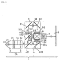
- FIG. 1 shows an optical system of a projection-type display apparatus according to a first exemplary embodiment not forming part of the present invention.
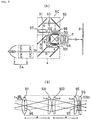
- a projection-type display apparatus 1 in this embodiment is comprised of an illumination optical system 2A constituted by a light source 2 and a uniform illumination optical device 3, a color separating optical system 4 for separating a white beam W outputted from the illumination optical system 2A through the uniform illumination optical device 3 into color beams R, G and B of red, green and blue, three liquid crystal panels 5R, 5G and 5B as light valves for modulating the color beams, a color synthesizing optical system 6 for synthesizing the modulated color beams again, and a projection lens 7 for magnifying and projecting the synthesized beam onto a screen 8.
- a light guide system 9 for guiding the green beam G among the color beams, separated by the color separating optical system 4, to the liquid crystal valve 5G.
- the light source 2 in this embodiment is constituted by a light source lamp 21 and a curved reflecting mirror 22.
- a tungsten halogen lamp, a metal halide lamp, a xenon lamp and so on can be used.
- the optical system 3 is constituted by first and second lens plates 31 and 32 arranged on a plane vertical to a center optical axis 1a thereof.
- the color separating optical system 4 is constituted by a blue/green reflecting dichroic mirror 401, a blue reflecting dichroic mirror 402 and a reflecting mirror 403.
- the blue and green beams B and G contained in the white beam W are reflected at a right angle by the blue/green reflecting dichroic mirror 401, and directed toward the blue reflecting dichroic mirror 402.
- the red beam R passes through this mirror 401, is reflected at a right angle by the reflecting mirror 403 located behind, and outputted from an outputting portion 404 for the red beam toward the color synthesizing optical system.
- the blue and green beams B and G reflected by the mirror 401 only the blue beam B is reflected at a right angle by the blue reflecting dichroic mirror 402, and outputted from an outputting portion 405 for the blue beam toward the color synthesizing optical system.
- the green beam G passed through the mirror 402 is outputted from an outputting portion 406 for the green beam toward the light guide system 9.
- the distances between the outputting portion of the uniform illumination optical device 3 for the white beam and the outputting portions 404, 405 and 406 for the color beams in the color separating optical system 4 are set to be equal.
- condenser lenses 101, 102 and 103 each of which consists of a planoconvex lens are respectively located on the outputted sides of the outputting portions 404, 405 and 406 of the color separating optical system 4 for the color beams. Therefore, the color beams outputted from the outputting portions come into the condenser lens 101-103 to be collimated.
- switching control operations are performed according to the image information by unillustrated drive means in these liquid crystal panels, thereby modulating the color beams passing therethrough.
- drive means a well-known type of drive means can be used as it is, and the explanation thereof is omitted in this embodiment.
- the green beam G is guided to the corresponding liquid crystal panel 5G through the light guide system 9, and modulated according to image information in the same manner as above.
- Each of the liquid crystal panels employed in this embodiment has a pixel pitch of less than 50 ⁇ m and uses a polysilicon TFT as a switching device.
- the light guide system 9 in this embodiment is constituted by an incident side reflecting mirror 91, an output side reflecting mirror 92 and an intermediate lens 93 located between the reflecting mirrors 91 and 92.
- the focal length of the intermediate lens 93 is set to be equal to the total optical path length of the light guide system 9.
- the focal length can be set within a range of approximately 0.9 to 1.1 times of the total optical path length of the light guide system 9.
- the distance of the green beam G is the longest, and therefore, the green beam G loses the most amount of light.
- the interposition of the light guide system 9 as in this embodiment can restrict the loss in the amount of light.
- a color beam passing through the light guide system 9 may be red or blue. However, since the amount of green light is more than those of other colors in an ordinary projection-type display apparatus, it is generally preferable to assign the green beam to the optical path passing through the light guide system 9. If brightness or evenness in image quality takes priority over color balance, it is allowable to assign the blue beam, which has a low spectral luminous efficacy and in which unevenness in luminous intensity is relatively difficult to detect, to the light guide system 9.
- the color synthesizing optical system 6 consists of a dichroic prism in this embodiment.
- a mirror composite system having dichroic mirrors arranged in the shape of X may be employed.
- each of the dichroic mirrors is an optical element which is rotationally asymmetrical about the center axis of a projection lens.
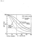
- FIG. 2 shows MTF characteristics in the projection-type display apparatus having the prism composite system in this embodiment and a projection-type display apparatus having a mirror composite system as a color synthesizing system.
- the horizontal axis indicates the spatial frequency (line/mm) representing the fineness of pixels of the display panel
- the vertical axis indicates MTF characteristics(%).
- Solid lines each indicate the characteristic of the projection optical system with the prism composite system.
- a bold solid line indicates the characteristic of the center portion of an image plane, and a thin solid line indicates that of the peripheral portion of the image plane.
- broken lines each indicate the characteristic of the projection optical system with the mirror composite system.
- a bold broken line indicates the characteristic of the center portion of the image plane, and a thin broken line indicates that of the peripheral portion of the image plane.
- the color beams are synthesized in the color synthesizing system consisting of a dichroic prism, and an optical image can be obtained and projected onto the screen 8 by the projection lens 7 under magnification.
- a lens close to a telecentric system is preferable as a projection lens.
- the uniform illumination optical device 3 consists of the first and second lens plates 31 and 32.
- the first lens plate 31 is formed from a matrix of a plurality of rectangular lenses 301
- the second lens plate 32 is similarly formed from a plurality of rectangular lenses 302.
- Each of the rectangular lenses 301 of the first lens plate 31 is shaped similarly to the liquid crystal panel to be illuminated. Images on these rectangular lenses 301 are superimposed onto the liquid crystal panel by the corresponding rectangular lenses 302 constituting the second lens plate 32. Therefore, the liquid crystal panel is illuminated with uniform illumination and little color unevenness.
- the rectangular lenses in the lens plates 31 and 32 are respectively arranged in a 4 by 3 matrix. It is preferable that the most split number of the lens plates in the vertical or horizontal direction be within a range of approximately 3 to 7. Furthermore, it is not always necessary to separate the first and second lens plates 31 and 32. These lens plates 31 and 32 can be brought closer together by making the size of each rectangular lens smaller and increasing the split number of the incident beam. Still furthermore, the lens plates 31 and 32 may be combined into a single lens plate.
- the horizontal axis indicates the split number of the first and second lens plates (integrator lenses), and the vertical axis indicates color unevenness, differences in color among the center portion (1 portion) and the peripheral portions (4 portions) on the screen 8, as differences on a U'V' chromaticity coordinate.
- a value indicated by a broken line is the largest color unevenness which is regarded as permissible as color unevenness.
- the split number be more than 3.
- the increase of the split number leads to an increase in cost from the viewpoint of production. Therefore, a practical split number is within a range of approximately 3 to 7.
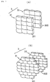
- Fig. 3(B) illustrates another arrangement example of the first and second lens plates 31 and 32 constituting the uniform illumination optical device 3.
- each of the lens plates is also constituted by rectangular lens plates of the same size.
- the split number in the vertical direction is 7.
- the split number in the horizontal direction is 3 in the top and bottom lines, 5 in the center three lines and 4 in other lines.
- the uniform illumination optical device 3 may be constituted by a first lens plate 31 consisting of a plurality of cylindrical lenses 301' and a second lens plate 32 consisting of a plurality of cylindrical lenses 302' as shown in Fig. 3(C).
- the luminous intensity is made uniform only in one direction, and the luminous intensity of the center of an object to be illuminated is higher than those of the cases shown in Figs. 3(A) and (B).
- the arrangement of the lenses is relatively simple, thinning of the lenses can be easily performed.
- a light emitting source close to a point source such as a tungsten halogen lamp, a metal halide lamp, a xenon lamp and so on.
- the beam emitted from the lamp is reflected by the reflecting mirror 22.
- the shape of the reflection plane of the reflecting mirror 22 may be elliptical, and in this case, a first focus is made coincident with the emitting portion of the light source lamp 21 and the second focus is made coincident with the center of the liquid crystal panel 5 (5R, 5G and 5B). As a result, the beam reflected by the reflecting mirror 22 advances toward the center of the liquid crystal panel 5.
- the size of the second lens plate 32 that is, the size of each of the rectangular lenses 302 constituting the lens plate 32 is set smaller than that of the first lens plate 31 so that the center of each rectangular lens 302 of the second lens plate 32 is positioned on a line between the center of each corresponding rectangular lens 301 of the first lens plate 31 and the center of the liquid crystal panel 5.
- Each of the rectangular lenses 301 of the first lens plate 31 condenses the beam onto the center of the corresponding rectangular lenses 302 of the second lens plate 32.
- the rectangular lenses 302 of the second lens plate 32 superimpose images on the corresponding rectangular lenses 301 of the first lens plate 31 onto a display area 5A (an area diagonally shaded in the figure) of the liquid crystal panel 5. Since the image in the outputting portion of the light source lamp 21 is thus formed on the center of each rectangular lens 302 of the second lens plate 32, the whole second lens plate 32 functions as a secondary light source.
- a chief ray 303 of a beam incident on the end of the display area 5A of the liquid crystal panel 5 coincides with a line which links the center of the second lens plate 32 and the end of the display area 5A.
- the illumination beam to the liquid crystal panel 5 is an diverged beam from the second lens plate 32, it is necessary to collimate the diverged beam in order to make a collimated beam incident on the liquid crystal panel 5.
- the condenser lenses 101, 102 and 103 are arranged in this embodiment.
- the focal length of each condenser lens is set equal to a distance b between the second lens plate 32 and the condenser lens.
- a planoconvex lens which is located with a convex plane facing the liquid crystal panel 5 is used as the condenser lens.
- the convex plane may be set to face the second lens plate 32.
- a double-convex lens or a Fresnel lens may be used instead of the planoconvex lens.
- the chief ray of the beam outputted through the liquid crystal panel 5 is made parallel to the center axis 1a of the whole illuminatio n optical system by arranging the condenser lenses 101, 102 and 103.
- Fig. 5(B) illustrates a variation of the illumination optical system.
- a parabolical plane is used as a reflection plane of the reflecting mirror 22 of the light source 2. Since the focus of the parabolical plane is made coincident with the emitting portion of the light source lamp 21 in this case, a beam reflected by the reflecting mirror 22 is almost parallel to the center axis 1a of the illumination system. Therefore, the uniform illumination optical device 3 used in this case is constituted by first and second lens plates 31' and 32' of the same size, and rectangular lenses constituting the lens plates each have the same focal length. Rectangular lenses 302' of the second lens plate 32' form an image on corresponding rectangular lenses of the first lens plate 31' at an infinite distance.
- a lens 306 is added in this case in order to form the image to be formed at an infinite distance onto the display area 5A of the liquid crystal panel 5.
- the focal length of the lens 306 is set to be equal to the distance between the lens 306 and the liquid crystal panel 5.
- the lens 306 may be integrally formed with the second lens plate 32.
- the distance between the lens plates 31 and 32 can be relatively long, and a reflecting mirror 33 can be interposed between the lens plates 31 and 32 as shown in Fig. 13.
- the volume of the uniform illumination optical system is almost a half of that in the above embodiment.
- all the optical systems can be arranged in an area close to a square as shown in the figure, and it contributes to downsizing of the whole apparatus.
- the light guide system 9 in this embodiment is constituted by the two reflecting mirrors 91 and 92 and the intermediate lens 93 located therebetween. Another arrangement of the light guide system applicable to this embodiment will now be described below.
- a light guide system 9A shown in Fig. 6 has the arrangement obtained by omitting the intermediate lens 93 from the light guide system 9 in this embodiment.
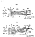
- a light guide system 9B shown in Fig. 7(A) has the arrangement in which an incident lens 94 is added on the incident side thereof and an outputting lens 95 is added on the output side thereof besides the arrangement of the light guide system 9 in this embodiment.
- the intermediate lens 93 is located just at the center of the whole optical path of the light guide system 9B, and when it is assumed that the total optical path length is 2a, the focal length of the intermediate lens 93 is set to be almost equal to a/2. Therefore, the intermediate lens 93 forms an image of an object 96 on the incident side of the light guide system 9B onto the output side thereof as a reversed image 97. In other words, the illumination distribution on the incident side is transferred with an 180-degree turn on the emission side.
- the illumination optical system provided with the uniform illumination optical device 3 is employed in this embodiment, the illumination distribution is almost symmetrical about the 180-degree turn. Therefore, even if the illumination distribution is turned or reversed, no color unevenness arises on the display.
- the incident lens 94 has a focal length which equals a distance a to the intermediate lens 93, and directs a main ray 9a of the beam G collimated through the condenser lens 103 toward the center of the intermediate lens 93. Therefore, an image on the second lens plate 32 on the output side of the uniform illumination optical device 3 is formed in the center of the intermediate lens 93. Furthermore, the outputting lens 95 also has a focal length set to be equal to a, and collimates and outputs the chief ray of the diverged beam outputted from the center of the intermediate lens 93.
- the incident lens 94 is, as shown in the figure, a planoconvex lens, and is located with a convex side thereof facing the incident side, thereby decreasing its spherical aberration.
- the output lens 95 is also a planoconvex lens located with a convex side thereof facing on the output side.
- the focal lengths of the incident lens 94 and the output lens 95 be each set within a range of approximately 0.5 to approximately 0.7 times of the total optical path length (2a) of the light guide system 9B.
- the focal length of the intermediate lens 93 be a little longer than 1/4 of the total optical path length (2a), and be set within a range of approximately 0.25 to approximately 0.4 times of the total optical path length.
- Fig. 8(A) illustrates a variation of the above-mentioned light guide system 9B.
- a lens 97 made by integrally forming the incident lens 94 and the condenser lens 103 located on this side in the direction of the optical path in the light guide system 9B.
- the focal length of the lens 97 is set at a value obtained by adding the refracting powers of the incident lens 94 and the condenser lens 103, in short, ab/(a+b) as shown in Fig. 8(B). It is preferable that the lens 97 be a double-convex lens in order to reduce spherical aberration.
- the intermediate lens 93 is constituted by two planoconvex lenses 931 and 932.
- the focal length of each of the planoconvex lenses 931 and 932 is set at a.
- Fig. 9 illustrates a variation of the light guide system 9C.
- an aspherical lens 98 is employed instead of the integrated lens 97 in the above light guide system 9C.
- the use of the aspherical lens makes spherical aberration even smaller than that in use of the double-convex lens. Therefore, the illumination distribution on the incident side of the light guide system can be transferred to the output side with extreme precision.
- the employed illumination optical system is provided with the uniform illumination optical device 3, and a dichroic prism, which is an axially symmetrical optical device, is used as the color synthesizing optical system. Therefore, it is possible to realize a projection-type display apparatus in which unevenness in color and luminous intensity is small and the illumination efficiency is high. Furthermore, since the color synthesizing system including a dichroic prism is used, the focal length of the projection lens can be shortened, and a large-scale display at a short distance can be performed. Consequently, the application of the constitution of this embodiment to a rear projector makes it possible to shorten the depth of the projector, and to make the projector compact.
- the focal lengths of the intermediate lens, the incident lens and the outputting lens which are optical devices constituting the light guide system, are set at proper values, it is possible to decrease the occurrence of color unevenness and the loss in the amount of light of the color beams passing through those optical devices, thereby restricting unevenness in color and luminous intensity of a projection image, and forming a bright image.
- the optical system can be compact and inexpensive. If the integrated lens is replaced with an aspherical lens, it is possible to make the optical system compact and reduce spherical aberration.
- the split number in the uniform illumination optical device is set within a range of 3 to 7 and the pixel pitch of the liquid crystal panel is set less than 50 ⁇ m, color unevenness, blurring and so on of the projection image can be restricted. Therefore, it is possible to realize a projection-type display apparatus capable of forming a projection image of high quality.
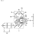
- FIG. 10 illustrates a projection-type display apparatus according to a second embodiment of the present invention.
- a projection-type display apparatus 100 in this embodiment is the same as the above-mentioned projection-type display apparatus 1 in the first embodiment except for the structure of a light guide system. Therefore, like components are denoted by like numerals, and the explanation thereof is omitted.
- a light guide system 9E in the projection-type display apparatus 100 of this embodiment is constituted by an incident side triangular prism 901, an output side triangular prism 902 and a quadratic prism 903 located between the triangular prisms 901 and 902.
- the total reflection plane 905 may be an optical flat surface merely made of glass or plastic. However, if the incident beam includes a light beam of an angle which is not totally reflected, it is preferable that the total reflection plane 905 be coated with a metal film, such as aluminum, silver and so on. Instead, coating with a dielectric multilayer reflective film may be conducted.
- the incident plane 904 and the outputting plane 906 serve to guide light by the total reflection as illustrated, each of them is needed to be an interface between air and the glass material and cannot be contact with adjacent optical elements. Therefore, it is necessary that five planes of the triangular prism 901 are all optical flat planes and, in some cases, the incident plane 904 and the outputting plane 906 thereof are required to be applied with a reflection attenuation coating. Particularly, it is preferable that a non-reflection coating be conducted on the interface between the triangular prism 901 and the adjacent triangular prism 903.
- Six planes of the quadratic prism 903 are all optical flat planes, and four planes 907 parallel to a main axis of the beam passing therethrough guide the light beam by total reflection.
- the triangular prism 902 on the output side of the quadratic prism 903 has the same structure as that of the triangular prism 901 on the incident side.
- the emitted beam enters the display area 5A of the liquid crystal panel 5G.
- the shape of the incident surface 904 of the triangular prism 901 and the shape of the emitting plane of the triangular prism 902 are almost the same as the rectangular shape of the display area 5A of the liquid crystal panel 5G.
- a uniform illumination optical device 3 of the illumination optical system is, as shown in Fig. 3, constituted by first and second lens plates 31 and 32 in each of which rectangular lenses are arranged in a matrix. Therefore, the incident surface 904 of the incident side triangular prism 901 is almost uniformly illuminated in relation to the rectangular shape thereof.
- the three prisms transfer the incident beam to the display area 5A of the liquid crystal panel 5G while keeping the amount of light, the collimated state and uniform brightness distribution of the incident beam. Though it is necessary to locate the triangular prism 902 on the output side and the liquid crystal panel 5G close to each other, if there is a distance which cannot be ignored, a prism or a lens for light guiding may be additionally located.
- the same advantage as that of the above-mentioned first embodiment can be obtained by the projection-type display apparatus having such constitution in this embodiment.
- a cylindrical light guide member formed from the combination of four reflecting mirrors may be employed.
- the quadratic prism 903 shown in Fig. 10(B) may be replaced with a cylindrical light guide system constituted by four reflectivity mirrors 903' shown in Fig. 10(C). Though the reflectance of light guide surfaces is a little lowered, the operation is not changed.
- the light guide system may be constituted by two upper and lower reflecting plates 911 and 912 and two reflecting mirrors 913 and 914 for folding the optical path. In this case, though the incident beam cannot be transferred without any loss in the amount of light, the loss amount can be reduced by shortening the focal length of the lens 103 to some extent. Since the illumination distribution cannot be also kept, this method is suited to the uniform illumination optical device using the cylindrical lenses shown in Fig. 3(C).
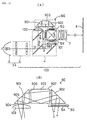
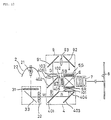
- FIG. 11 illustrates a projection-type display apparatus according to a fourth embodiment, the principles of which can be used in the present invention.
- a projection-type display apparatus 200 in this embodiment is contrived so as to compactly house an optical system in a case 201.
- the optical system in this embodiment is constituted by an illumination optical system 2B, a color separating optical system 4, light valves 5R, 5G and 5B, a color synthesizing optical system 6, a projection lens 7 and a light guide system 9D.
- the color separating optical system 4, the light valves 5R, 5G and 5B, the color synthesizing optical system 6 and the projection lens 7 are the same as those in the apparatus 100 of the first embodiment.
- the light guide system 9D is the same as that shown in Fig. 9(A). Therefore, components corresponding to the above-mentioned ones are denoted by like numerals, and the explanation thereof is omitted.
- the direction of an emitted beam from a light source lamp 21 is folded at a right angle in the illumination optical system 2B so that a center axis of a beam emitted from the illumination optical system 2B is parallel to an optical axis 7a of the projection lens 7.
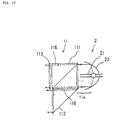
- the illumination optical system 2B is provided with a polarized beam conversion system 11.
- the illumination optical system 2B in this embodiment is constituted by a light source 2 composed of the lamp 21 and a reflecting mirror 22, the polarized beam conversion device 11 located on the emission side of the light source 2, and a uniform illumination optical device 3A on the emission side of the polarized beam conversion device 11.
- the polarized beam conversion device 11 in this embodiment is constituted by a polarizing beam splitter 111, a reflecting mirror 112, and a_/2 phase plate 113.
- a random polarized beam 114 emitted from the light source 2 is separated into two linearily polarized beams, a P polarized beam 115 and an S polarized beam 116, by the polarizing beam splitter 111 which is a polarized beam separating element. Since the polarized beam separating function of the polarizing beam splitter 111 has a dependence on an incident angle, a light source provided with a lamp having a short arc length and capable of emitting a beam excellent in parallelism is suitable.
- the separated P polarized beam 115 passes through the _/2 phase plate 113 which is a polarizing plane rotating element, a polarization plane thereof is turned at an angle of 90° and the P polarized beam 115 is converted into an S polarized beam.
- the S polarized beam 116 is outputted as it is while an optical path thereof is merely folded by the prismatic reflecting mirror 112.
- the reflecting mirror 112 is made of, for example, an aluminum evaporated film. Since the reflecting mirror 112 has a higher reflectivity rate for an S polarized beam than that for a P polarized beam, the optical path of the S polarized beam is folded by the reflecting mirror 112.
- an ordinary plane reflecting mirror may be used instead of such prismatic mirror.
- the random polarized beam 114 from the light source is outputted as an S polarized beam by passing through the polarized beam conversion device 11 having such structure.
- the P polarized beam is converted into the S polarized beam in this embodiment, to the contrary, it is allowable that the S polarized beam is converted into a P polarized beam, and the P polarized beam is emitted from the polarized beam conversion device 11.
- the uniform illumination optical device 3A located on the output side of the polarized beam conversion device 11 is constituted by a first lens plate 31 located on a plane perpendicular to the chief axis of the outputted S polarized beam 116, a second lens plate 32 orthogonal to the first lens plate 31, and a reflecting mirror 33 located between the lens plates 31 and 32 for folding the optical path at a right angle.
- the first and second lens plates each have the same structure as that in the first embodiment.
- the light beam incident on the uniform illumination optical device 3A is thus folded at a right angle and outputted.
- the outputted white s polarized beam is separated into beams of primary colors by the color separating optical system 4.
- the separated color beams are synthesized by the color synthesizing optical system 6 consisting of a dichroic prism, and magnified and projected onto a screen 8 through the projection lens 7 under magnification.
- the optical path is formed in the apparatus 200 of this embodiment so that the direction of the projection beam is parallel and reverse to the emission direction of the illumination optical system 2B, and a cooling fan 12 for restricting heat generation of the light source lamp 21 is located on the back side of the light source 2 in the case 201.
- the illumination optical system 2B is provided with the polarized beam conversion device 11. Therefore, the random polarized beam emitted from the light source is converted into two specific linearily polarized beams, and the converted beams are efficiently superposed and output with little loss incident to the emission. That can realize a bright illumination optical system capable of outputting only polarized beams at high efficiency. Furthermore, since the outputted polarized beams pass through the uniform illumination optical device 3A in this embodiment, unevenness in color and luminous intensity caused in the light source is restricted and illumination light of high uniformity can be obtained.
- an illumination optical system has a uniform illumination optical device
- a color synthesizing system has a dichroic prism
- a light guide system is located on the optical path of a color beam having the longest optical path length in a color separating system
- emitted color beams separated through the color separating system are collimated by condenser lenses and applied onto light valves. Therefore, according to the present invention, unevenness in color and luminous intensity of light from a light source is restricted by the uniform illumination optical device.
- the color synthesizing system is a prism composite system which causes less unevenness in color and luminous intensity than a mirror composite system, and therefore, the unevenness in color and so on hardly arises therein.
- the loss in the amount of light is small and the illumination efficiency is enhanced. Therefore, according to the present invention, it is possible to realize a projection-type display apparatus which causes less unevenness in color and luminous intensity than ever and has a high illumination efficiency.
- the focal lengths of lenses which are components of the light guide system, are set at appropriate values, or a prism is used as the light guide system. According to this constitution, since unevenness in color and loss in the amount of light in the light guide system can be restricted, it is possible to form a projection image having little unevenness in color and a high illumination efficiency.
- a dichroic prism which is an element rotationally symmetrical about the center axis of the projection optical system, is used as the color synthesizing system, and a liquid crystal panel having a small pixel pitch of less than approximately 50 ⁇ m is used as a light valve. Therefore, according to the present invention, it is possible to form a projection image of high resolution and to downsize the whole apparatus by employing a liquid crystal panel using a polysilicon TFT or the like which is easy to make compact.
- the split number of the lens plates constituting the uniform illumination optical device is set within a range of 3 to 7 in the present invention, it is possible to form a projection image whose unevenness in color is restricted.
- the illumination optical system is provided with a polarized beam conversion device in the present invention, it is possible to restrict the emission loss of the light emitted from the light source lamp, and therefore, to form a bright projection image.
- the optical path is formed in the projection-type optical system of the present invention so that the projection light can be outputted in the direction reverse and parallel to the onward direction of the light beam emitted from the illumination optical system, and a cooling means for the light source lamp is located on the output side of the projection light in the apparatus case.
- the cooling means is located on the reverse side to a viewer of the projection image, and air from the cooling means is exhausted to the reverse side to the viewer. Therefore, it is advantageous in preventing the noise and exhausted air from the cooling means from disturbing the viewer.
- a back focus of the projection lens of the optical system is short, a large-scale projection at a short distance is easy to perform. Therefore, it is possible to realize a projection-type display apparatus suitable for presentation use and home theater use. Furthermore, since the back focus of the projection lens is short, it is possible to realize a projection lens having a small F number by a small number of lenses, and therefore, to lower the production cost of the apparatus.
Abstract
Claims (10)
- Projecteur (1) comprenant une source de lumière (2), un moyen de séparation de couleurs (4) pour séparer un faisceau de lumière (W) émis par ladite source de lumière (2) en des faisceaux (R, G, B) de trois couleurs, trois modulateurs de lumière (5R, 5G, 5B) pour moduler lesdits faisceaux de lumière séparés (R, G, B), un moyen optique d'éclairement uniforme (3) interposé sur un chemin optique entre ladite source de lumière (2) et ledit moyen de séparation de couleurs (4) de manière à convertir ledit faisceau de lumière (W) issu de ladite source de lumière (2) en une pluralité de faisceaux rectangulaires et à transmettre chacun desdits faisceaux rectangulaires vers ledit moyen de séparation de couleurs, un moyen de guidage de lumière (9) situé sur un chemin optique d'un faisceau de couleur (G) ayant le plus long chemin optique parmi lesdits faisceaux de couleur séparés par ledit moyen de séparation de couleurs (4) et étant respectivement incident sur lesdits trois modulateurs de lumière (5R, 5G, 5B), un moyen de synthèse de couleur (6) pour synthétiser lesdits faisceaux de couleur (R, G, B) modulés à travers lesdits modulateurs de lumière (5R, 5G, 5B), et une lentille de projection (7) pour projeter ledit faisceau synthétisé et modulé sur un écran (8), caractérisé en ce que :dans lequel, chaque faisceau de ladite pluralité desdits faisceaux rectangulaires convertis par ledit moyen optique d'éclairement uniforme (3) est superposé auxdits modulateurs de lumière (5R, 5G, 5B) à travers lesdites trois lentilles de condenseur (101, 102, 103) ettrois lentilles de condenseur (101, 102, 103) sont respectivement situées au niveau des sorties dudit moyen de séparation de couleurs (4) pour transmettre lesdits faisceaux de lumière de couleur pour convertir lesdits faisceaux sortant dudit moyen optique d'éclairement uniforme (3) en des faisceaux pratiquement collimatés,
dans lequel, ledit moyen de guidage de lumière (9) est muni d'un prisme triangulaire de côté d'incidence (901) situé au niveau du côté d'incidence pour plier le chemin optique à angle droit, d'un prisme triangulaire de côté de sortie (902) situé au niveau du côté de sortie pour plier le chemin optique à angle droit, et un élément de guidage de lumière (903) situé entre lesdits prismes triangulaires (901, 902). - Projecteur selon la revendication 1, dans lequel ledit élément de guidage de lumière (903) est un prisme quadratique.
- Projecteur selon la revendication 2, dans lequel les interfaces desdits prismes triangulaires (901, 902) et dudit prisme quadratique (903) sont recouvertes d'une couche anti-reflet.
- Projecteur selon l'une quelconque des revendications 1 à 3, dans lequel une surface de réflexion totale de chacun desdits prismes triangulaires (901, 902) est recouverte d'un film métallique.
- Projecteur selon l'une quelconque des revendications 1 à 3, dans lequel un plan de réflexion totale de chacun desdits prismes triangulaires (901, 902) est recouvert d'un film multicouche diélectrique.
- Projecteur selon l'une quelconque des revendications 1 à 5, dans lequel lesdits modulateurs de lumière (5R, 5G, 5B) sont des écrans à cristaux liquides, et un pas des pixels de chacun desdits écrans à cristaux liquides est inférieur à approximativement 50 µm.
- Projecteur selon l'une quelconque des revendications 1 à 6, dans lequel ledit moyen optique d'éclairement uniforme (3) comporte au moins une lame de lentilles (31) constituée d'une pluralité de lentilles (301) disposées dans un plan perpendiculaire à un axe maítre (1a) de ladite lumière (W) émise par ladite source de lumière (2), et le nombre divisé de ladite lame de lentilles dans une direction est compris entre approximativement 3 et approximativement 7.
- Projecteur selon l'une quelconque des revendications 1 à 7, dans lequel un faisceau de couleur devant traverser ledit moyen de guidage de lumière (9) est soit un faisceau vert, soit un faisceau bleu.
- Projecteur selon l'une quelconque des revendications 1 à 8, dans lequel ledit moyen optique d'éclairement uniforme (3) est constitué d'une première lame de lentilles (31), d'une seconde lame de lentilles (32) et d'un miroir réfléchissant (33) interposé entre lesdites lames de lentilles (31, 32).
- Projecteur selon l'une quelconque des revendications 1 à 9, dans lequel il est proposé un moyen de conversion de faisceau polarisé (11) situé entre ladite source de lumière (2) et ledit moyen optique d'éclairement uniforme (3), et ledit moyen de conversion de faisceau polarisé (11) est constitué d'un élément de séparation de faisceau polarisé (111) pour séparer un faisceau à polarisation aléatoire (114) issu de ladite source de lumière (2) en deux faisceaux à polarisation directe P (115) et S (116), et un élément de rotation du plan de polarisation (113) permettant de faire tourner un plan de polarisation de l'un desdits deux faisceaux polarisés séparés (115, 116) à un angle de 90 °, de façon à le faire coïncider avec celui de l'autre faisceau à polarisation directe.
Priority Applications (2)
| Application Number | Priority Date | Filing Date | Title |
|---|---|---|---|
| EP02077916A EP1261213A1 (fr) | 1993-03-16 | 1994-03-16 | Dispositif d'affichage de type projection |
| EP02077915A EP1257128B1 (fr) | 1993-03-16 | 1994-03-16 | Dispositif d'affichage du type par projection |
Applications Claiming Priority (4)
| Application Number | Priority Date | Filing Date | Title |
|---|---|---|---|
| JP55952/93 | 1993-03-16 | ||
| JP5595293 | 1993-03-16 | ||
| JP5595293 | 1993-03-16 | ||
| PCT/JP1994/000419 WO1994022042A1 (fr) | 1993-03-16 | 1994-03-16 | Dispositif de visualisation par projection |
Related Child Applications (2)
| Application Number | Title | Priority Date | Filing Date |
|---|---|---|---|
| EP02077915A Division EP1257128B1 (fr) | 1993-03-16 | 1994-03-16 | Dispositif d'affichage du type par projection |
| EP02077916A Division EP1261213A1 (fr) | 1993-03-16 | 1994-03-16 | Dispositif d'affichage de type projection |
Publications (3)
| Publication Number | Publication Date |
|---|---|
| EP0646828A1 EP0646828A1 (fr) | 1995-04-05 |
| EP0646828A4 EP0646828A4 (fr) | 1995-07-19 |
| EP0646828B1 true EP0646828B1 (fr) | 2003-11-12 |
Family
ID=13013415
Family Applications (3)
| Application Number | Title | Priority Date | Filing Date |
|---|---|---|---|
| EP02077916A Withdrawn EP1261213A1 (fr) | 1993-03-16 | 1994-03-16 | Dispositif d'affichage de type projection |
| EP02077915A Expired - Lifetime EP1257128B1 (fr) | 1993-03-16 | 1994-03-16 | Dispositif d'affichage du type par projection |
| EP94910021A Expired - Lifetime EP0646828B1 (fr) | 1993-03-16 | 1994-03-16 | Dispositif de visualisation par projection |
Family Applications Before (2)
| Application Number | Title | Priority Date | Filing Date |
|---|---|---|---|
| EP02077916A Withdrawn EP1261213A1 (fr) | 1993-03-16 | 1994-03-16 | Dispositif d'affichage de type projection |
| EP02077915A Expired - Lifetime EP1257128B1 (fr) | 1993-03-16 | 1994-03-16 | Dispositif d'affichage du type par projection |
Country Status (7)
| Country | Link |
|---|---|
| US (5) | US5626409A (fr) |
| EP (3) | EP1261213A1 (fr) |
| JP (1) | JP3254680B2 (fr) |
| DE (2) | DE69433318T2 (fr) |
| HK (1) | HK1014584A1 (fr) |
| TW (1) | TW249846B (fr) |
| WO (1) | WO1994022042A1 (fr) |
Cited By (1)
| Publication number | Priority date | Publication date | Assignee | Title |
|---|---|---|---|---|
| CN103744183A (zh) * | 2014-01-24 | 2014-04-23 | 哈尔滨工业大学 | 一种红外宽波段多干扰复合光学系统 |
Families Citing this family (95)
| Publication number | Priority date | Publication date | Assignee | Title |
|---|---|---|---|---|
| FR2699690B1 (fr) * | 1992-12-22 | 1995-01-27 | Thomson Csf | Projecteur d'images mobiles à faible champ. |
| EP1261213A1 (fr) | 1993-03-16 | 2002-11-27 | Seiko Epson Corporation | Dispositif d'affichage de type projection |
| DE4435450A1 (de) * | 1993-10-04 | 1995-04-06 | Matsushita Electric Ind Co Ltd | Flüssigkristalleinheit und Projektionsanzeige unter Verwendung einer Flüssigkristalleinheit |
| EP1310805B1 (fr) * | 1994-12-27 | 2006-05-17 | Seiko Epson Corporation | Unité à prismes et dispositif d'affichage par projection l'utilisant |
| US6147802A (en) | 1994-12-28 | 2000-11-14 | Seiko Epson Corporation | Polarization luminaire and projection display |
| US5871266A (en) * | 1995-06-26 | 1999-02-16 | Nissho Giken Kabushiki Kaisha | Projection-type display device |
| JP3606649B2 (ja) * | 1995-10-13 | 2005-01-05 | ソニー株式会社 | プロジェクタ装置 |
| JP4003234B2 (ja) * | 1996-04-10 | 2007-11-07 | セイコーエプソン株式会社 | 投写型表示装置 |
| JPH1031425A (ja) * | 1996-07-17 | 1998-02-03 | Canon Inc | 投射型表示装置 |
| JP3791130B2 (ja) | 1996-08-19 | 2006-06-28 | セイコーエプソン株式会社 | 投写型表示装置 |
| JP3473335B2 (ja) | 1996-08-19 | 2003-12-02 | セイコーエプソン株式会社 | 投写型表示装置 |
| JP3374018B2 (ja) * | 1996-09-12 | 2003-02-04 | 松下電器産業株式会社 | 前面投射型液晶表示装置 |
| TW561296B (en) * | 1996-10-30 | 2003-11-11 | Seiko Epson Corp | Projection display and its illuminating optical system |
| TW434444B (en) * | 1996-10-30 | 2001-05-16 | Seiko Epson Corp | Projection display and illuminating optical system for it |
| JPH10186547A (ja) * | 1996-10-30 | 1998-07-14 | Seiko Epson Corp | 投写型表示装置 |
| JP3414164B2 (ja) * | 1996-10-31 | 2003-06-09 | ミノルタ株式会社 | 液晶プロジェクタ |
| EP1431809B1 (fr) * | 1996-10-31 | 2014-06-18 | Hitachi Consumer Electronics Co., Ltd. | Projecteur à cristaux liquides |
| US6005655A (en) * | 1996-10-31 | 1999-12-21 | Minolta Co., Ltd. | Projector capable of projecting polarized illumination light |
| EP0841821A3 (fr) * | 1996-11-06 | 2000-01-12 | Canon Kabushiki Kaisha | Appareil de projection |
| JPH10148885A (ja) * | 1996-11-19 | 1998-06-02 | Sony Corp | プロジェクタ装置 |
| JP3298437B2 (ja) | 1996-12-18 | 2002-07-02 | セイコーエプソン株式会社 | 光学素子、偏光照明装置および投写型表示装置 |
| US5959778A (en) * | 1997-01-31 | 1999-09-28 | Nikon Corporation | Projection-display apparatus |
| US6257726B1 (en) | 1997-02-13 | 2001-07-10 | Canon Kabushiki Kaisha | Illuminating apparatus and projecting apparatus |
| DE69830441T2 (de) | 1997-03-28 | 2005-12-08 | Seiko Epson Corp. | Optisches Beleuchtungssystem und Anzeigegerät vom Projektionstyp |
| JP2939237B2 (ja) * | 1997-04-09 | 1999-08-25 | 三星電子株式会社 | 反射型プロジェクター |
| US6024452A (en) * | 1997-04-22 | 2000-02-15 | 3M Innovative Properties Company | Prismatic light beam homogenizer for projection displays |
| US6529250B1 (en) * | 1997-05-22 | 2003-03-04 | Seiko Epson Corporation | Projector |
| US6247816B1 (en) * | 1997-08-07 | 2001-06-19 | International Business Machines Corporation | Optical system for projection displays using spatial light modulators |
| JPH1164848A (ja) * | 1997-08-25 | 1999-03-05 | Minolta Co Ltd | 液晶プロジェクタ |
| EP0899600B1 (fr) * | 1997-08-26 | 2003-10-22 | Victor Company of Japan, Ltd. | Affichage du type à projection avec dispositif d'éclairage et séparateurs de polarisation optique |
| JPH11149061A (ja) * | 1997-09-12 | 1999-06-02 | Minolta Co Ltd | 光源装置および照明装置 |
| JP4374624B2 (ja) * | 1997-09-22 | 2009-12-02 | ソニー株式会社 | 映像表示装置 |
| JPH11174407A (ja) * | 1997-12-05 | 1999-07-02 | Canon Inc | 投影装置 |
| US6186629B1 (en) * | 1997-12-22 | 2001-02-13 | Sony Corporation | Optical device and display apparatus |
| JP3892130B2 (ja) * | 1998-01-21 | 2007-03-14 | 株式会社半導体エネルギー研究所 | 液晶プロジェクタ |
| JPH11212022A (ja) * | 1998-01-28 | 1999-08-06 | Nec Corp | 映像投射装置 |
| US6273568B1 (en) * | 1998-02-05 | 2001-08-14 | Canon Kabushiki Kaisha | Projection apparatus |
| JPH11249010A (ja) * | 1998-02-27 | 1999-09-17 | Minolta Co Ltd | プロジェクター光学系 |
| US6734838B1 (en) * | 1998-05-18 | 2004-05-11 | Dimension Technologies Inc. | Enhanced resolution for image generation |
| US6587159B1 (en) * | 1998-05-29 | 2003-07-01 | Texas Instruments Incorporated | Projector for digital cinema |
| US6113239A (en) * | 1998-09-04 | 2000-09-05 | Sharp Laboratories Of America, Inc. | Projection display system for reflective light valves |
| US6478430B2 (en) * | 1998-12-24 | 2002-11-12 | Canon Kabushiki Kaisha | Illumination apparatus and projection apparatus |
| US7595771B1 (en) * | 1998-12-31 | 2009-09-29 | Texas Instruments Incorporated | Electro-optical, tunable, broadband color modulator |
| US6513934B1 (en) | 1999-02-17 | 2003-02-04 | Canon Kabushiki Kaisha | Projection apparatus and observation apparatus |
| US6634755B1 (en) | 1999-02-17 | 2003-10-21 | Canon Kabushiki Kaisha | Illuminating device and projector |
| US6457832B1 (en) | 1999-02-19 | 2002-10-01 | Canon Kabushiki Kaisha | Illumination apparatus and projection apparatus compensating for transverse aberration at an illumination surface |
| US6995917B1 (en) | 1999-04-08 | 2006-02-07 | Sharp Laboratories Of America, Inc. | Projection display system using polarized light |
| US6254237B1 (en) | 1999-04-30 | 2001-07-03 | David K. Booth | Multi-pixel microlens illumination in electronic display projector |
| JP3661491B2 (ja) * | 1999-05-28 | 2005-06-15 | 住友化学株式会社 | 画像表示装置および防眩性直線偏光板 |
| US6259430B1 (en) * | 1999-06-25 | 2001-07-10 | Sarnoff Corporation | Color display |
| WO2001001703A1 (fr) * | 1999-06-28 | 2001-01-04 | Koninklijke Philips Electronics N.V. | Dispositif d'ecran de projection comportant un systeme integrateur pourvu d'un prisme tunnel |
| JP2003515761A (ja) * | 1999-11-22 | 2003-05-07 | コーニンクレッカ フィリップス エレクトロニクス エヌ ヴィ | 画像投射システム |
| JP4075284B2 (ja) * | 2000-04-21 | 2008-04-16 | コニカミノルタオプト株式会社 | 照明光学装置 |
| JP3661569B2 (ja) * | 2000-06-30 | 2005-06-15 | セイコーエプソン株式会社 | プロジェクタ |
| US6788469B2 (en) * | 2000-12-30 | 2004-09-07 | Texas Instruments Incorporated | Automated lamp focus |
| JPWO2002056110A1 (ja) | 2001-01-15 | 2004-05-20 | セイコーエプソン株式会社 | プロジェクタ |
| JP2002223454A (ja) * | 2001-01-26 | 2002-08-09 | Canon Inc | 投射型画像表示装置 |
| DE10127617A1 (de) * | 2001-06-07 | 2002-12-12 | Zeiss Carl Jena Gmbh | Projektionsanordnung |
| DE10127621A1 (de) * | 2001-06-07 | 2002-12-12 | Zeiss Carl Jena Gmbh | Anordnung zum Projizieren eines Bildes auf eine Projektionsfläche |
| DE10127620A1 (de) * | 2001-06-07 | 2002-12-12 | Zeiss Carl Jena Gmbh | Anordnung zum Projizieren eines mehrfarbigen Bildes auf eine Projektionsfläche |
| US6985163B2 (en) * | 2001-08-14 | 2006-01-10 | Sarnoff Corporation | Color display device |
| US7136035B2 (en) * | 2001-12-11 | 2006-11-14 | Seiko Epson Corporation | Projection type display, a display and a drive method thereof |
| EP1345453A1 (fr) * | 2002-03-12 | 2003-09-17 | Chromagic Technologies Corporation | Source de lumière pour projecteur à cristaux liquides |
| US7159986B2 (en) | 2002-05-20 | 2007-01-09 | Swales & Associates, Inc. | Wide field collimator |
| CN2546916Y (zh) | 2002-06-05 | 2003-04-23 | 上海力保科技有限公司 | 彩扩机数码曝光装置 |
| WO2004008023A1 (fr) * | 2002-07-11 | 2004-01-22 | Sharp Kabushiki Kaisha | Dispositif de guidage de lumiere et dispositif d'affichage |
| KR100441506B1 (ko) | 2002-07-16 | 2004-07-23 | 삼성전자주식회사 | 영상투사장치 |
| US7317465B2 (en) * | 2002-08-07 | 2008-01-08 | Hewlett-Packard Development Company, L.P. | Image display system and method |
| US7172288B2 (en) * | 2003-07-31 | 2007-02-06 | Hewlett-Packard Development Company, L.P. | Display device including a spatial light modulator with plural image regions |
| JP3873845B2 (ja) * | 2002-08-07 | 2007-01-31 | 三菱電機株式会社 | 映像表示装置 |
| US7029127B2 (en) * | 2003-03-06 | 2006-04-18 | Seiko Epson Corporation | Projector |
| US7172290B2 (en) * | 2003-06-09 | 2007-02-06 | Wavien, Inc. | Light pipe based projection engine |
| US6918671B2 (en) * | 2003-07-11 | 2005-07-19 | Hewlett-Packard Development Company, L.P. | Projector and method |
| JP4422986B2 (ja) * | 2003-08-22 | 2010-03-03 | キヤノン株式会社 | 画像表示装置 |
| JP4366163B2 (ja) * | 2003-09-25 | 2009-11-18 | キヤノン株式会社 | 照明装置及び露光装置 |
| JP4556424B2 (ja) * | 2003-12-09 | 2010-10-06 | セイコーエプソン株式会社 | プロジェクタ |
| US20050195370A1 (en) * | 2004-03-02 | 2005-09-08 | Gore Makarand P. | Transmissive/reflective light engine |
| JP4165479B2 (ja) | 2004-09-08 | 2008-10-15 | セイコーエプソン株式会社 | プロジェクタ |
| JP4222285B2 (ja) | 2004-10-06 | 2009-02-12 | セイコーエプソン株式会社 | プロジェクタ |
| JP4254685B2 (ja) | 2004-10-07 | 2009-04-15 | セイコーエプソン株式会社 | プロジェクタ |
| JP4923533B2 (ja) * | 2005-03-11 | 2012-04-25 | セイコーエプソン株式会社 | 光学多層膜、光学素子、反射ミラーおよびプロジェクタ |
| US7578594B2 (en) * | 2005-07-26 | 2009-08-25 | Hewlett-Packard Development Company, L.P. | Illumination source activation based on temperature sensing |
| KR100739720B1 (ko) * | 2005-08-16 | 2007-07-13 | 삼성전자주식회사 | 컬러필터 불요형 액정 디스플레이 장치 |
| US7641350B2 (en) * | 2005-11-28 | 2010-01-05 | Jds Uniphase Corporation | Front surface mirror for providing white color uniformity for polarized systems with a large range of incidence angles |
| US20090073510A1 (en) * | 2006-02-16 | 2009-03-19 | Kurt Eugene Spears | Passive Transparent Media Adapter |
| JP2007286430A (ja) * | 2006-04-18 | 2007-11-01 | Sony Corp | 複合光学素子及び投影光学装置 |
| US20070273797A1 (en) * | 2006-05-26 | 2007-11-29 | Silverstein Barry D | High efficiency digital cinema projection system with increased etendue |
| CN101369055B (zh) * | 2007-08-16 | 2011-05-04 | 鸿富锦精密工业(深圳)有限公司 | 投影设备及其光圈调节方法和光源装置 |
| CN101408711A (zh) * | 2007-10-11 | 2009-04-15 | 鸿富锦精密工业(深圳)有限公司 | 投影系统 |
| TWI355520B (en) * | 2008-08-21 | 2012-01-01 | All Real Technology Co Ltd | Artificial light source generator |
| JP2010152046A (ja) * | 2008-12-25 | 2010-07-08 | Seiko Epson Corp | プロジェクタ |
| JP5322331B2 (ja) | 2010-05-28 | 2013-10-23 | Necディスプレイソリューションズ株式会社 | 照明光学系および投写型表示装置 |
| US8950874B2 (en) * | 2011-09-16 | 2015-02-10 | Ricoh Company, Ltd. | Projection optical system and image display apparatus |
| JP5947925B2 (ja) | 2014-02-12 | 2016-07-06 | キヤノン株式会社 | 電気機器、画像投射装置および撮像装置 |
| JP2019035922A (ja) * | 2017-08-21 | 2019-03-07 | セイコーエプソン株式会社 | 照明装置およびプロジェクター |
Citations (1)
| Publication number | Priority date | Publication date | Assignee | Title |
|---|---|---|---|---|
| US3296923A (en) * | 1965-01-04 | 1967-01-10 | Gen Electric | Lenticulated collimating condensing system |
Family Cites Families (26)
| Publication number | Priority date | Publication date | Assignee | Title |
|---|---|---|---|---|
| US5075798A (en) * | 1984-10-22 | 1991-12-24 | Seiko Epson Corporation | Projection-type display device |
| US4787737A (en) * | 1986-03-26 | 1988-11-29 | Casio Computer Co., Ltd. | Projection display apparatus |
| JPS62237485A (ja) * | 1986-04-08 | 1987-10-17 | セイコーエプソン株式会社 | 投射型表示装置 |
| JPS6346490A (ja) * | 1986-04-15 | 1988-02-27 | セイコーエプソン株式会社 | 投写型液晶表示装置 |
| JP2562300B2 (ja) * | 1986-05-02 | 1996-12-11 | セイコーエプソン株式会社 | 投写型カラ−表示装置 |
| JP2537607B2 (ja) * | 1986-11-05 | 1996-09-25 | セイコーエプソン株式会社 | 投写型カラ−表示装置 |
| JPH0769539B2 (ja) * | 1986-11-12 | 1995-07-31 | 株式会社日立製作所 | 液晶表示装置 |
| JPH0194985A (ja) * | 1987-03-27 | 1989-04-13 | Ishii:Kk | 立体表示が可能な塗料及び表示方法並に立体表示板 |
| JPH0725777Y2 (ja) * | 1987-12-16 | 1995-06-07 | カシオ計算機株式会社 | 液晶プロジェクタ |
| JPH0267312U (fr) * | 1988-11-10 | 1990-05-22 | ||
| US4943154A (en) * | 1988-02-25 | 1990-07-24 | Matsushita Electric Industrial Co., Ltd. | Projection display apparatus |
| JPH0225016A (ja) * | 1988-07-13 | 1990-01-26 | Nec Corp | 露光装置 |
| JPH0267312A (ja) * | 1988-08-31 | 1990-03-07 | Shin Etsu Chem Co Ltd | エポキシ樹脂組成物 |
| JPH0642125B2 (ja) * | 1988-10-04 | 1994-06-01 | シャープ株式会社 | プロジェクション装置 |
| US5157523A (en) * | 1989-03-29 | 1992-10-20 | Matsushita Electric Industrial Co., Ltd. | Projection type liquid crystal display unit including orthogonal phase plates |
| NL8901077A (nl) * | 1989-04-28 | 1990-11-16 | Koninkl Philips Electronics Nv | Optische belichtingsstelsel en projectie-apparaat voorzien van een dergelijk stelsel. |
| JPH03152526A (ja) * | 1989-11-09 | 1991-06-28 | Nippon Avionics Co Ltd | 液晶カラー投射装置 |
| EP0434041B1 (fr) * | 1989-12-20 | 1996-09-11 | Canon Kabushiki Kaisha | Dispositif d'illumination polarisé |
| NL9001610A (nl) * | 1990-07-16 | 1992-02-17 | Philips Nv | Beeldprojektie-inrichting. |
| JPH0486725A (ja) * | 1990-07-31 | 1992-03-19 | Toshiba Corp | 投射型表示装置 |
| FR2669440B1 (fr) * | 1990-11-21 | 1994-08-26 | Sextant Avionique | Dispositif de visualisation en couleur par projection mettant en óoeuvre des valves optiques. |
| FR2676207B1 (fr) | 1991-05-06 | 1993-08-27 | Aerospatiale | Train d'atterrissage pour aerodynes, a traverses en materiau composite. |
| FR2676288B1 (fr) * | 1991-05-07 | 1994-06-17 | Thomson Csf | Collecteur d'eclairage pour projecteur. |
| JP3142012B2 (ja) * | 1991-08-01 | 2001-03-07 | ソニー株式会社 | 投写型画像表示装置 |
| EP1261213A1 (fr) * | 1993-03-16 | 2002-11-27 | Seiko Epson Corporation | Dispositif d'affichage de type projection |
| US5605390A (en) * | 1996-01-25 | 1997-02-25 | Sarif, Inc. | Optical projector |
-
1994
- 1994-03-16 EP EP02077916A patent/EP1261213A1/fr not_active Withdrawn
- 1994-03-16 WO PCT/JP1994/000419 patent/WO1994022042A1/fr active IP Right Grant
- 1994-03-16 EP EP02077915A patent/EP1257128B1/fr not_active Expired - Lifetime
- 1994-03-16 JP JP52087094A patent/JP3254680B2/ja not_active Expired - Lifetime
- 1994-03-16 DE DE69433318T patent/DE69433318T2/de not_active Expired - Lifetime
- 1994-03-16 DE DE69433600T patent/DE69433600T2/de not_active Expired - Lifetime
- 1994-03-16 US US08/335,778 patent/US5626409A/en not_active Ceased
- 1994-03-16 EP EP94910021A patent/EP0646828B1/fr not_active Expired - Lifetime
- 1994-04-02 TW TW083102917A patent/TW249846B/zh not_active IP Right Cessation
-
1997
- 1997-01-14 US US08/783,236 patent/US6120152A/en not_active Expired - Lifetime
-
1998
- 1998-07-17 US US09/118,182 patent/USRE36850E/en not_active Expired - Lifetime
- 1998-12-28 HK HK98115924A patent/HK1014584A1/xx not_active IP Right Cessation
-
2000
- 2000-03-16 US US09/526,446 patent/US6309073B1/en not_active Expired - Lifetime
-
2001
- 2001-10-30 US US09/984,363 patent/US20020057420A1/en not_active Abandoned
Patent Citations (1)
| Publication number | Priority date | Publication date | Assignee | Title |
|---|---|---|---|---|
| US3296923A (en) * | 1965-01-04 | 1967-01-10 | Gen Electric | Lenticulated collimating condensing system |
Cited By (2)
| Publication number | Priority date | Publication date | Assignee | Title |
|---|---|---|---|---|
| CN103744183A (zh) * | 2014-01-24 | 2014-04-23 | 哈尔滨工业大学 | 一种红外宽波段多干扰复合光学系统 |
| CN103744183B (zh) * | 2014-01-24 | 2016-01-20 | 哈尔滨工业大学 | 一种红外宽波段多干扰复合光学系统 |
Also Published As
| Publication number | Publication date |
|---|---|
| JP3254680B2 (ja) | 2002-02-12 |
| USRE36850E (en) | 2000-09-05 |
| US6309073B1 (en) | 2001-10-30 |
| US20020057420A1 (en) | 2002-05-16 |
| EP0646828A4 (fr) | 1995-07-19 |
| DE69433600D1 (de) | 2004-04-08 |
| EP1257128B1 (fr) | 2004-03-03 |
| DE69433318T2 (de) | 2004-09-16 |
| EP0646828A1 (fr) | 1995-04-05 |
| DE69433600T2 (de) | 2005-02-03 |
| DE69433318D1 (de) | 2003-12-18 |
| WO1994022042A1 (fr) | 1994-09-29 |
| US5626409A (en) | 1997-05-06 |
| EP1257128A1 (fr) | 2002-11-13 |
| TW249846B (fr) | 1995-06-21 |
| HK1014584A1 (en) | 1999-09-30 |
| US6120152A (en) | 2000-09-19 |
| EP1261213A1 (fr) | 2002-11-27 |
Similar Documents
| Publication | Publication Date | Title |
|---|---|---|
| EP0646828B1 (fr) | Dispositif de visualisation par projection | |
| US5467154A (en) | Projection monitor | |
| US6402325B1 (en) | Illuminating optical system having multiple light sources and lenticular arrays for use with a projection-type display unit | |
| US6497488B1 (en) | Illumination system and projector | |
| EP0717865B1 (fr) | Systemes d'affichage par projection a cristaux liquides | |
| CN101351745B (zh) | 投影系统及其光束调制方法 | |
| US7520617B2 (en) | Reflection type projection display apparatus | |
| US6174060B1 (en) | Projection-type display apparatus having polarized beam splitters and an illuminating device | |
| JP4956887B2 (ja) | 投写光学装置及びそれを用いた画像表示装置 | |
| US5653520A (en) | Liquid crystal display projector | |
| US6987618B2 (en) | Polarization converting device, illumination optical system and projector | |
| US6637891B2 (en) | Optical system of liquid crystal projector | |
| JP2001142141A (ja) | プロジェクタ | |
| JPH0743658A (ja) | 投写型表示装置 | |
| JP3613256B2 (ja) | 投写型表示装置 | |
| WO2003062902A1 (fr) | Unite d'affichage d'image | |
| JP3486608B2 (ja) | 投写型表示装置 | |
| JPH046543A (ja) | 投写型表示装置および該装置に用いる色分解光学装置 | |
| Röder et al. | Full-colour diffraction-based optical system for light-valve projection displays | |
| JP2000250137A (ja) | 照明光学装置及びプロジェクタ装置 | |
| JP3680859B2 (ja) | 投写型表示装置 | |
| JP3365412B2 (ja) | 投写型表示装置 | |
| JPH04149426A (ja) | 投射型表示装置 | |
| JP2007114347A (ja) | プロジェクタ | |
| JP3506142B1 (ja) | 投写型表示装置 |
Legal Events
| Date | Code | Title | Description |
|---|---|---|---|
| PUAI | Public reference made under article 153(3) epc to a published international application that has entered the european phase |
Free format text: ORIGINAL CODE: 0009012 |
|
| 17P | Request for examination filed |
Effective date: 19941107 |
|
| AK | Designated contracting states |
Kind code of ref document: A1 Designated state(s): DE FR GB |
|
| A4 | Supplementary search report drawn up and despatched | ||
| AK | Designated contracting states |
Kind code of ref document: A4 Designated state(s): DE FR GB |
|
| 17Q | First examination report despatched |
Effective date: 19970729 |
|
| GRAH | Despatch of communication of intention to grant a patent |
Free format text: ORIGINAL CODE: EPIDOS IGRA |
|
| GRAS | Grant fee paid |
Free format text: ORIGINAL CODE: EPIDOSNIGR3 |
|
| GRAA | (expected) grant |
Free format text: ORIGINAL CODE: 0009210 |
|
| AK | Designated contracting states |
Kind code of ref document: B1 Designated state(s): DE FR GB |
|
| REG | Reference to a national code |
Ref country code: GB Ref legal event code: FG4D |
|
| REF | Corresponds to: |
Ref document number: 69433318 Country of ref document: DE Date of ref document: 20031218 Kind code of ref document: P |
|
| REG | Reference to a national code |
Ref country code: HK Ref legal event code: GR Ref document number: 1014584 Country of ref document: HK |
|
| ET | Fr: translation filed | ||
| PLBE | No opposition filed within time limit |
Free format text: ORIGINAL CODE: 0009261 |
|
| STAA | Information on the status of an ep patent application or granted ep patent |
Free format text: STATUS: NO OPPOSITION FILED WITHIN TIME LIMIT |
|
| 26N | No opposition filed |
Effective date: 20040813 |
|
| PGFP | Annual fee paid to national office [announced via postgrant information from national office to epo] |
Ref country code: DE Payment date: 20130314 Year of fee payment: 20 Ref country code: FR Payment date: 20130325 Year of fee payment: 20 Ref country code: GB Payment date: 20130313 Year of fee payment: 20 |
|
| REG | Reference to a national code |
Ref country code: DE Ref legal event code: R071 Ref document number: 69433318 Country of ref document: DE |
|
| REG | Reference to a national code |
Ref country code: GB Ref legal event code: PE20 Expiry date: 20140315 |
|
| PG25 | Lapsed in a contracting state [announced via postgrant information from national office to epo] |
Ref country code: DE Free format text: LAPSE BECAUSE OF EXPIRATION OF PROTECTION Effective date: 20140318 Ref country code: GB Free format text: LAPSE BECAUSE OF EXPIRATION OF PROTECTION Effective date: 20140315 |