EP0564252A2 - Procédé et appareil d'enregistrement à jets d'encre - Google Patents
Procédé et appareil d'enregistrement à jets d'encre Download PDFInfo
- Publication number
- EP0564252A2 EP0564252A2 EP93302493A EP93302493A EP0564252A2 EP 0564252 A2 EP0564252 A2 EP 0564252A2 EP 93302493 A EP93302493 A EP 93302493A EP 93302493 A EP93302493 A EP 93302493A EP 0564252 A2 EP0564252 A2 EP 0564252A2
- Authority
- EP
- European Patent Office
- Prior art keywords
- recording
- scan
- record
- ink
- scans
- Prior art date
- Legal status (The legal status is an assumption and is not a legal conclusion. Google has not performed a legal analysis and makes no representation as to the accuracy of the status listed.)
- Granted
Links
Images


Classifications
-
- B—PERFORMING OPERATIONS; TRANSPORTING
- B41—PRINTING; LINING MACHINES; TYPEWRITERS; STAMPS
- B41J—TYPEWRITERS; SELECTIVE PRINTING MECHANISMS, i.e. MECHANISMS PRINTING OTHERWISE THAN FROM A FORME; CORRECTION OF TYPOGRAPHICAL ERRORS
- B41J2/00—Typewriters or selective printing mechanisms characterised by the printing or marking process for which they are designed
- B41J2/005—Typewriters or selective printing mechanisms characterised by the printing or marking process for which they are designed characterised by bringing liquid or particles selectively into contact with a printing material
- B41J2/01—Ink jet
-
- B—PERFORMING OPERATIONS; TRANSPORTING
- B41—PRINTING; LINING MACHINES; TYPEWRITERS; STAMPS
- B41J—TYPEWRITERS; SELECTIVE PRINTING MECHANISMS, i.e. MECHANISMS PRINTING OTHERWISE THAN FROM A FORME; CORRECTION OF TYPOGRAPHICAL ERRORS
- B41J19/00—Character- or line-spacing mechanisms
- B41J19/14—Character- or line-spacing mechanisms with means for effecting line or character spacing in either direction
- B41J19/142—Character- or line-spacing mechanisms with means for effecting line or character spacing in either direction with a reciprocating print head printing in both directions across the paper width
- B41J19/147—Colour shift prevention
-
- B—PERFORMING OPERATIONS; TRANSPORTING
- B41—PRINTING; LINING MACHINES; TYPEWRITERS; STAMPS
- B41J—TYPEWRITERS; SELECTIVE PRINTING MECHANISMS, i.e. MECHANISMS PRINTING OTHERWISE THAN FROM A FORME; CORRECTION OF TYPOGRAPHICAL ERRORS
- B41J2/00—Typewriters or selective printing mechanisms characterised by the printing or marking process for which they are designed
- B41J2/005—Typewriters or selective printing mechanisms characterised by the printing or marking process for which they are designed characterised by bringing liquid or particles selectively into contact with a printing material
- B41J2/01—Ink jet
- B41J2/135—Nozzles
- B41J2/145—Arrangement thereof
-
- B—PERFORMING OPERATIONS; TRANSPORTING
- B41—PRINTING; LINING MACHINES; TYPEWRITERS; STAMPS
- B41J—TYPEWRITERS; SELECTIVE PRINTING MECHANISMS, i.e. MECHANISMS PRINTING OTHERWISE THAN FROM A FORME; CORRECTION OF TYPOGRAPHICAL ERRORS
- B41J29/00—Details of, or accessories for, typewriters or selective printing mechanisms not otherwise provided for
- B41J29/38—Drives, motors, controls or automatic cut-off devices for the entire printing mechanism
-
- G—PHYSICS
- G06—COMPUTING; CALCULATING OR COUNTING
- G06K—GRAPHICAL DATA READING; PRESENTATION OF DATA; RECORD CARRIERS; HANDLING RECORD CARRIERS
- G06K15/00—Arrangements for producing a permanent visual presentation of the output data, e.g. computer output printers
- G06K15/02—Arrangements for producing a permanent visual presentation of the output data, e.g. computer output printers using printers
- G06K15/10—Arrangements for producing a permanent visual presentation of the output data, e.g. computer output printers using printers by matrix printers
- G06K15/102—Arrangements for producing a permanent visual presentation of the output data, e.g. computer output printers using printers by matrix printers using ink jet print heads
- G06K15/105—Multipass or interlaced printing
- G06K15/107—Mask selection
-
- H—ELECTRICITY
- H04—ELECTRIC COMMUNICATION TECHNIQUE
- H04N—PICTORIAL COMMUNICATION, e.g. TELEVISION
- H04N1/00—Scanning, transmission or reproduction of documents or the like, e.g. facsimile transmission; Details thereof
- H04N1/04—Scanning arrangements, i.e. arrangements for the displacement of active reading or reproducing elements relative to the original or reproducing medium, or vice versa
- H04N1/19—Scanning arrangements, i.e. arrangements for the displacement of active reading or reproducing elements relative to the original or reproducing medium, or vice versa using multi-element arrays
- H04N1/191—Scanning arrangements, i.e. arrangements for the displacement of active reading or reproducing elements relative to the original or reproducing medium, or vice versa using multi-element arrays the array comprising a one-dimensional array, or a combination of one-dimensional arrays, or a substantially one-dimensional array, e.g. an array of staggered elements
- H04N1/1911—Simultaneously or substantially simultaneously scanning picture elements on more than one main scanning line, e.g. scanning in swaths
- H04N1/1913—Scanning adjacent picture elements in different scans of the array, e.g. in complementary checkerboard patterns
- H04N1/1915—Scanning adjacent picture elements in different scans of the array, e.g. in complementary checkerboard patterns with subscan displacement of the array between successive scans
-
- H—ELECTRICITY
- H04—ELECTRIC COMMUNICATION TECHNIQUE
- H04N—PICTORIAL COMMUNICATION, e.g. TELEVISION
- H04N1/00—Scanning, transmission or reproduction of documents or the like, e.g. facsimile transmission; Details thereof
- H04N1/46—Colour picture communication systems
- H04N1/50—Picture reproducers
-
- B—PERFORMING OPERATIONS; TRANSPORTING
- B41—PRINTING; LINING MACHINES; TYPEWRITERS; STAMPS
- B41J—TYPEWRITERS; SELECTIVE PRINTING MECHANISMS, i.e. MECHANISMS PRINTING OTHERWISE THAN FROM A FORME; CORRECTION OF TYPOGRAPHICAL ERRORS
- B41J19/00—Character- or line-spacing mechanisms
- B41J19/14—Character- or line-spacing mechanisms with means for effecting line or character spacing in either direction
- B41J19/142—Character- or line-spacing mechanisms with means for effecting line or character spacing in either direction with a reciprocating print head printing in both directions across the paper width
-
- G—PHYSICS
- G06—COMPUTING; CALCULATING OR COUNTING
- G06K—GRAPHICAL DATA READING; PRESENTATION OF DATA; RECORD CARRIERS; HANDLING RECORD CARRIERS
- G06K2215/00—Arrangements for producing a permanent visual presentation of the output data
- G06K2215/0002—Handling the output data
- G06K2215/0062—Handling the output data combining generic and host data, e.g. filling a raster
- G06K2215/0071—Post-treatment of the composed image, e.g. compression, rotation
- G06K2215/0074—Depleting the image
-
- G—PHYSICS
- G06—COMPUTING; CALCULATING OR COUNTING
- G06K—GRAPHICAL DATA READING; PRESENTATION OF DATA; RECORD CARRIERS; HANDLING RECORD CARRIERS
- G06K2215/00—Arrangements for producing a permanent visual presentation of the output data
- G06K2215/0082—Architecture adapted for a particular function
- G06K2215/0094—Colour printing
-
- H—ELECTRICITY
- H04—ELECTRIC COMMUNICATION TECHNIQUE
- H04N—PICTORIAL COMMUNICATION, e.g. TELEVISION
- H04N1/00—Scanning, transmission or reproduction of documents or the like, e.g. facsimile transmission; Details thereof
- H04N1/04—Scanning arrangements, i.e. arrangements for the displacement of active reading or reproducing elements relative to the original or reproducing medium, or vice versa
- H04N1/12—Scanning arrangements, i.e. arrangements for the displacement of active reading or reproducing elements relative to the original or reproducing medium, or vice versa using the sheet-feed movement or the medium-advance or the drum-rotation movement as the slow scanning component, e.g. arrangements for the main-scanning
-
- H—ELECTRICITY
- H04—ELECTRIC COMMUNICATION TECHNIQUE
- H04N—PICTORIAL COMMUNICATION, e.g. TELEVISION
- H04N2201/00—Indexing scheme relating to scanning, transmission or reproduction of documents or the like, and to details thereof
- H04N2201/04—Scanning arrangements
- H04N2201/0402—Arrangements not specific to a particular one of the scanning methods covered by groups H04N1/04 - H04N1/207
- H04N2201/0466—Selectively scanning in one or the other of two opposite directions, e.g. in the forward or the reverse direction
- H04N2201/0468—Scanning in both of the two directions, e.g. during the forward and return movements
Definitions
- the present invention relates to an ink jet recording method and apparatus, which record an image on a recording medium by ejecting ink droplets according to image data.
- a recording apparatus of this type uses a head prepared by integrating a plurality of ink ejection orifices and ink channels as a recording head (to be referred to as a multi-head hereinafter) in which a plurality of recording elements are integrated and aligned for the purpose of an increase in recording speed. Furthermore, a color recording apparatus normally comprises a plurality of multi-heads.
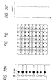
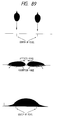
- a multi-head 91 is constituted by eight multi-nozzles 92 for ejecting ink droplets 93.
- the multi-nozzles 92 ideally eject the ink droplets in a uniform amount and in a uniform direction, as shown in Fig. 71A. If such ejection is performed, dots having a uniform size land on a sheet surface, as shown in Fig. 71B, and a uniform image free from the density nonuniformity can be obtained as a whole (Fig. 71C).
- each nozzle suffers from a variation, as described above.
- ink droplets having various sizes are ejected from the nozzles in various directions, as shown in Fig. 72A, and land on a sheet surface, as shown in Fig. 72B.
- a blank portion which does not satisfy an area factor of 100%, conversely, a portion where dots unnecessarily overlap each other, and a white line (at the center of Fig. 72B) periodically appear in the head main scan direction.
- the group of dots which landed in the state shown in Fig. 72B has a density distribution shown in Fig. 72C in the nozzle alignment direction, and consequently, such a phenomenon is normally observed as a density nonuniformity by human eye.
- the multi-head 91 is scanned (main scan) three times, and a half area in units of four pixels is completed by two passes.
- the eight nozzles of the multi-head are divided into two groups respectively including upper four nozzles and lower four nozzles. Dots to be printed by one nozzle in a single scan are obtained by thinning out given image data to about a half according to a predetermined image data arrangement. In the second scan, dots corresponding to the remaining half image data are printed, thus completing the area in units of four pixels.
- the above-mentioned recording method will be referred to as a divisional recording method hereinafter.
- image data is divisionally thinned out to predetermined complementary arrangements in the first and second scans.
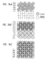
- image data arrangement a checker pattern in which dots are printed on every other pixels in the vertical and horizontal directions is normally used, as shown in Fig. 74A. Therefore, a unit print area (in units of four pixels) is completed by the first scan for printing dots in a checker pattern and the second scan for printing dots in a reverse checker pattern.
- Figs. 74A, 74B, and 74C explain how to complete a predetermined record area using the checker and reverse checker patterns by the multi-head having eight nozzles like in Figs. 71A to 73C.
- dots are recorded in a checker pattern using lower four nozzles (Fig. 74A).
- a sheet is fed by four pixels (1/2 the head length), and dots are recorded in a reverse checker pattern ⁇ (Fig. 74B).
- the sheet is fed by four pixels (1/2 the head length), and dots are recorded in the checker pattern again (Fig. 74C). In this manner, when the sheet feed operation in units of four pixels, and recording operations of the checker and reverse checker patterns are alternately performed, a record area in units of four pixels is completed for each scan.
- the invention is characterized by comprising means for forming an overlapping portion by overlapping two adjacent main scans by setting a sheet feed width of each main scan to be smaller than the width of the main scan, and means for printing dots of the overlapping portion so as not to overlap each other in the two main scans".
- a thinning mask is defined as one for "alternately printing odd and even rows in every other columns" in one case.
- odd rows are printed in the first scan
- even rows are printed in the second scan.
- odd and even rows are randomly printed in each scan.
- the thinning mask and the sheet feed width are not completely limited.
- a recording method wherein a pseudo pixel (super pixel) as a group of several pixels is formed for the purpose of gradation expression and multi-color expression, and an alternate thinning print operation at two-dimensionally non-adjacent pixel positions in units of pseudo pixels (super pixels) is disclosed. It is described that according to this method, "once a system for realizing the method is installed in a software program or printer firmware, since the program can be called by the numbers of color combinations designated in association with super pixels, high print quality can be achieved without unnecessarily complicating an operation for creating a computer program for generating a large number of colors", and simplified programming for achieving multi-color expression is listed as one effect. It is also described that since each super pixel is intended to be perceived as a single uniform color, color blurring within each super pixel is harmless.
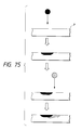
- Fig. 75 is a sectional view of a normally used recording ink and a landing state of the ink printed on a medium (paper sheet).
- Fig. 75 illustrates a state wherein two different color inks (dots) are absorbed (recorded) at almost neighboring positions to have a time distance therebetween. It is to be noted that, in an overlapping portion of two dots, the subsequently recorded dot tends to extend under the previously recorded dot in the sheet depth direction. Such a phenomenon is caused for the following reason.
- the previously ejected ink dyestuff is preferentially coupled to the recording medium as along as there is no large coupling force difference depending on the types of dyestuffs, and remains in a large amount near the surface portion of the recording medium.
- the subsequently ejected ink dyestuff is not easily coupled to the surface portion of the recording medium, and is fixed after it sinks deep in the sheet depth direction.
- a priority color varies depending on the print order of the two different inks, and consequently, two different colors are expressed for visual characteristics of man.
- four color heads are arranged in the order of black, cyan, magenta, and yellow from the right, and main scans are performed by reciprocally moving the heads in the head alignment direction (right-and-left direction). In a forward scan, the heads are moved rightward, and simultaneously perform recording. At this time, since the recording order on a sheet surface follows the alignment order of the heads, for example, when a green (cyan + yellow) signal is input to a given area, inks are absorbed by each pixel in the order of cyan and yellow.
- Japanese Laid-Open Patent Application No. 58-194541 by the same applicant (Canon K.K.) as the present invention discloses a technique wherein a plurality of recording element arrays are arranged parallel to each other, upon execution of a main scan for recording a dot matrix by reciprocally moving the recording element arrays in a direction perpendicular to the recording element arrays, dots fewer than all dots in at least one of rows and columns of the recording dot matrix are intermittently recorded in a forward main scan, and remaining dots in at least one of rows and columns of the recording dot matrix are intermittently recorded in a backward main scan, so that the forward and backward main scans have different overlay recording orders of overlay recording dots using the plurality of recording element arrays.
- the sheet feed width is set to be smaller than a normal width unlike in the previously described divisional recording, and the effect of this reference is to prevent deterioration of image quality caused by color mis-registration (color nonuniformity) of a recorded image caused by overlay recording of color inks.
- dot positions to be recorded in each scan are not particularly limited.
- a horizontal thinning pattern used for alternately recording dots in only the vertical direction, and a vertical thinning pattern alternately repeated in only the horizontal direction are described in addition to checker patterns (checker and reverse checker patterns).
- Japanese Laid-Open Patent Application No. 55-113573 discloses an arrangement for performing reciprocal recording using checker patterns (checker and reverse checker patterns) although it is not limited to a color printer.
- This reference inhibits continuous print operations of neighboring dots, thereby preventing a dot distortion caused by printing a neighboring dot before a previously printed dot is dried. Therefore, in this reference, a thinning mask is limited to a checker pattern like in USP No. 4,748,453.
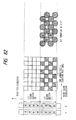
- the amount of an ink droplet is designed so that ink spreads wider than an area for each pixel on a sheet surface. This is to eliminate any blank portion in an area corresponding to a print duty of 100%. Therefore, even when the divisional recording method is executed, although recording pixels themselves are printed at only 50%, an almost 100% area of a recording medium (recording sheet) is covered by dots, as shown in Fig. 76.
- Fig. 77 is a sectional view of the sheet surface in this case. In Fig.
- Reference numeral 2001 indicates a state of inks immediately after the print operation in the first pass (forward scan).
- a solid black portion represents a cyan ink
- a hatched portion represents a yellow ink. Since the yellow and cyan inks are printed at an identical position to have a very small time distance therebetween, when they are absorbed by the sheet, the cyan ink is less blurred in a high-density state, and the yellow ink is largely blurred to extend to portions under and around the cyan ink in a low-density state. Also, at this time, the absorbing range of these inks extends over neighboring pixel positions, and as shown in Fig. 76, almost the entire sheet surface is filled with the ink dots.
- Fig. 78 illustrates a state wherein the above-mentioned two print areas appear.
- the lower half nozzles of the heads determine the priority color of each area, and the priority color is reversed between the forward and backward scans. Since two areas having the different priority colors are alternately formed, color nonuniformity still appears in the divisional print method, and deteriorates an image, thus preventing practical applications of the reciprocal print operations.
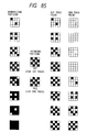
- image data are sent as actual signals after multi-value data representing certain gradation levels are binarized by a predetermined binarization method such as a dither method to have a predetermined pattern. Therefore, the number of pixels recorded in the first pass may be considerably different from the number of pixels recorded in the second pass depending on a thinning mask.
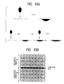
- Figs. 81(A) to 84 Such a phenomenon will be described below with reference to Figs. 81(A) to 84.
- the four colors are cyan (c), magenta (m), yellow (y), and black (k).
- an intermediate color (yellowish green) image obtained by overlaying the c and y inks respectively at print duties of 62.5% and 100% as shown in Fig. 81(A) is printed.
- a pixel indicated by a pin stripe pattern is a pixel on which c and y dots are printed, and a pixel indicated by a hatching pattern is a pixel on which only a y dot is printed.
- Figs. 81(A) is to be printed using a checker mask, c and y dots are printed at a duty of 50% on all possible pixel positions allowed by the checker mask (Fig. 81(B)) in the first pass. In the second pass, c and y dots are printed at the remaining duties, i.e., respectively at duties of 12.5% and 50%.
- the c and y heads respectively eject the inks, as shown in Figs. 81(D) and 81(E), and Figs. 81(F) and 81(G).
- Fig. 82 illustrates the ejection positions of the c and y recording heads in the first scan of the divisional recording method, and a dot formation state on a recording medium as a result of recording.
- a pin stripe pattern represents that both the c and y heads eject the inks on an identical pixel
- a hatched pattern represents that only the y head ejects the ink.
- each recording head uses four nozzles in a record section (1), and records dots in a checker pattern.
- dots in each of which the c and y inks overlap each other are formed in the checker pattern on the recording medium.
- the sheet is fed by an L/2 width, and the dots recorded in the first scan are moved to a record section (2).
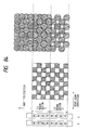
- Fig. 83 illustrates the ejection positions in the second scan, and a dot formation state on the recording medium as a result of recording.
- each head prints dots in a reverse checker pattern using both the record sections (1) and (2).
- dots formed by the record section (2) overlap the dots recorded in the checker pattern in the first scan, thus completing recording.
- the sheet is fed by another L/2 width, so that the dots formed by the recording section (2) are moved outside the record section, and the dots formed by the record section (1) are moved to the record section (2).
- Fig. 83 expresses the overlapping portions, so that the dots recorded in the second scan extend under the dots recorded in the first scan.
- Fig. 84 illustrates the ejection positions in the third scan, and a dot formation state on the recording medium as a result of recording.
- each head prints dots in the checker pattern opposite to the second scan using both the record sections (1) and (2).
- dots formed by the record section (2) overlap the dots recorded in the reverse checker pattern in the second scan, thus completing recording.
- the portion corresponding to the record section (2), and the portion outside the record section, on which recording has been completed in the second scan have different color tones, and cause color nonuniformity although they have same ejected ink amount.
- a cause for this phenomenon is considered as follows. That is, since the dots are formed in the checker pattern first on the portion outside the record section, many dots formed by ejecting the c and y inks on identical pixel positions are present on the surface portion of the recording medium. In contrast to this, on the portion corresponding to the record section (2), since many dots formed by only the y ink are present on the surface portion of the recording medium, this portion forms yellowish green in which the yellow color tone is relatively strong.
- a method of eliminating the above-mentioned defect a method wherein the number of pixels per color landed in each scan is averaged by adopting the divisional thinning arrangement, which is asynchronous with the arrangement of image data for gradation expression in an area gradation method, so as to eliminate a color tone difference of the scans, is proposed.
- thinning patterns 601 and 602 shown in Fig. 86 are used in place of thinning patterns 501 and 502 shown in Fig. 85, so that the first and second passes have the same number of landed pixels, thereby obtaining a good image.
- a landing state obtained when the second dot is printed on the sheet surface on which the ink is completely absorbed is different from a landing state obtained when the second dot lands on a position adjacent to the first dot before the first ink droplet is completely absorbed, i.e., before the absorbed ink is blurred.
- the landing states of the two dots are similar to each other.
- a bi-directional 2-pass print method of an ink jet recording apparatus For the sake of simplicity, a state of a green image obtained by printing cyan and yellow dots at duties of 100% within a 4 ⁇ 4 matrix will be exemplified.
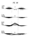
- Figs. 87 and 88 are views for explaining the conventional bi-directional print method, and illustrate the landing states of color dots in the first pass (forward scan) and the second pass (backward scan) when thinning masks 201 and 202 are used.
- the mask pattern 201 is used in the first pass, and the mask pattern 202 is used in the second pass. In the same pass, cyan and yellow dots, and even other color dots are printed using the same mask. A print state to be obtained when green image data 203 is input to all pixels will be described below.
- the heads are aligned in the order of black, cyan, magenta, and yellow with respect to the forward moving direction of the carriage. Therefore, in the first pass (forward scan), in order to form the green image 203, cyan dots are printed first, and yellow dots are printed after a short delay time (204). Conversely, in the second pass (backward scan), yellow dots are printed first, and thereafter, cyan dots are printed (205).
- a state 401 corresponds to an ink state immediately after the first pass print when viewed in a sheet section.
- a solid black portion represents the cyan ink
- a hatched portion represents the yellow ink. Since the yellow ink is printed at the same position as the cyan ink to have a very small time distance, it lands to overlap the cyan ink. When these inks are absorbed by the sheet in this state, a state 402 is attained. Since the cyan ink lands before the yellow ink to contact the sheet surface, it is less blurred, and has a high density.
- the state 204 in Fig. 87 corresponds to this print state when viewed from above the sheet surface.
- a capital letter represents an ink color having a high density and serving as a priority color
- a small letter represents an ink color having a low density.
- the high-density cyan (c) dots and the low-density yellow (y) dots are printed at pixel positions of the mask 201 in the first pass.
- the absorbing range of these inks extends to the neighboring pixel position, as can be seen from the state 402, and in this state, the sheet surface is almost filled with the ink dots.
- the ink dots are printed on the sheet surface on which neighboring ink dots have already been absorbed, as indicated by a state 403.
- the yellow ink is printed first, and the cyan ink is printed later in the second pass.
- the inks are absorbed in this state, finally, they do not clearly appear on the surface portion, as indicated by a state 404. Therefore, as indicated by the state 205 as well, both the cyan and yellow inks are largely blurred and have a low density.
- the density of only the cyan ink printed in the first pass is emphasized, and a green image having cyan as a priority color tone is formed on this print area (206).
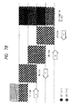
- Fig. 79 shows the absorbing state of a monochrome ink in the first and second passes like in Fig. 77.
- a state 2101 represents a landing state immediately after the first pass print
- states 2102 and 2103 represent landing states after the second pass print when viewed in a sheet section.
- the second pass print is performed immediately after the first pass print
- the second pass print is performed after a certain delay time after the first pass print.
- the time distance generated by reciprocally scanning the carriage is sufficient with respect to the order of the time difference that causes the density difference between the above-mentioned states. This factor appears as a new defect upon execution of the reciprocal print operations. This defect will be described below with reference to Fig. 80.
- the head performs a forward scan in the direction of an arrow from a position 2201 to perform recording corresponding to a first scan width.
- a sheet is fed by a width 1/2 the scan width, and the head then performs a backward scan in the opposite direction in turn from a position 2202 shown in Fig. 80.
- the head performs the forward scan again from a position 2203 to perform recording in the direction of the arrow. Recording intervals of the second pass at positions 1 to 6 of the print area completed at this time are compared. More specifically, at positions 3 and 4, after the first pass print is completed, the second pass print is performed immediately after the sheet is fed by a 1/2 width.
- the second pass print is performed after an elapse of a time required for reciprocally scanning the carriage once.
- the two print operations are performed at just an intermediate time distance. Therefore, as has already been described above with reference to Fig. 79, the positions 1 and 6 have the highest density, the positions 2 and 5 have the next highest density, and the positions 3 and 4 have the lowest surface density since the ink is absorbed deepest. Therefore, the density nonuniformity appears on the left-hand side area where the positions 1 and 4 repetitively appear at an interval of the 1/2 width in the vertical direction, and on the right-hand side area where the positions 3 and 6 repetitively appear at the interval of the 1/2 width in the vertical direction, thus deteriorating image quality.
- the blurring state to non-print pixel positions in the first pass causes dependency of the density on the recording interval between the first and second passes, and it can be understood from this respect as well that actual applications of the reciprocal print method have been impossible so far.
- monochrome recording has been exemplified. This phenomenon also appears together with color nonuniformity in mixed-color recording, as has already been described above, and in this case, it is recognized as right and left different color nonuniformity portions or different color tones.
- the following factor is known as a defect influencing the recording time distance.
- the carriage When the recording apparatus performs a head recovery scan to maintain its own driving scans during recording or waits for transfer of recording data, the carriage is temporarily set in a rest state.
- a rest state causes density nonuniformity which occurs irregularly on the order still larger than that of the time distance nonuniformity described above. More specifically, when the carriage is set in a rest state after the first pass print is completed, and the second pass print is performed after some time distance, a corresponding record area has a higher density than other areas.
- the density nonuniformity caused by such a factor will be referred to as rest nonuniformity to be distinguished from the time distance nonuniformity.
- the TP paper has a particularly low ink absorption speed as compared to other media, and the affinity force between ink droplets, which land on the sheet surface but are not completely absorbed, overcomes the absorption force of the coating layer on the TP paper. Therefore, when two or more such ink droplets are present at neighboring positions, as shown in Fig. 89, the ink droplets draw each other, and are coupled to form a large ink droplet at a position displaced from their original landing positions.
- Such a phenomenon is unique to a recording medium such as the TP paper having a low ink absorption speed, and is called "beading".
- the second scan is performed on an area contiguous with the first scan area.
- the affinity force of ink droplets acts, and ink droplets at the end portion are drawn to the center of the second scan width by the same phenomenon as that in the first scan described above.
- the density of the end portion is lowered (Fig. 90B).
- the end portions having a low density are formed adjacent to each other between two each adjacent recording areas of the first and second scans, and a plurality subsequent scans. These end portions form white lines between two each recording areas, and impair the uniformity of the entire image, thus considerably deteriorating image quality (Fig. 90C).
- a recording medium such as TP paper having a low ink absorption speed has been described. Even in a recording medium such as coated paper having high ink absorbency, an image defect occurs on a connection area between two adjacent scans although a phenomenon in this case is different from the above-mentioned one. Even in general paper, since some sheets have poor ink absorbency like in the TP paper but some other sheets have absorbency equivalent to the coated paper, an image defect inevitably occurs on a connection area.
- Fig. 91A is a sectional view showing a state wherein an ink droplet of a predetermined amount lands on and is absorbed by the sheet surface
- Fig. 91B is a sectional view showing a state wherein two ink droplets obtained by equally dividing the above-mentioned amount land on and are absorbed by the sheet surface at a time interval.
- Fig. 91C shows a state wherein images on two image areas are completed by two scans. Since an ink dot is designed to have a size larger than one pixel area, two or more dots overlap each other on all areas. At a boundary portion, since the extrusion portion is divisionally recorded by two scans at a time interval, a connection line having a higher density than that of other areas is undesirably formed. Also, the time interval between adjacent record scans is not always constant due to a different data transfer time, a recovery operation of the recording apparatus main body, and the like. When the recording head stands by at the home position after some record scans are completed, the density of the connection area is further increased, and image quality is further deteriorated. The density nonuniformity appearing in such a carriage rest state will be referred to as rest nonuniformity hereinafter.
- the defects described above on TP paper, coated paper, and the like can be avoided to some extent. More specifically, according to the divisional recording method, since an image in a single area.is completed by two different groups of nozzles, the density nonuniformity in the single image area can be prevented, while a connection line in units of scans using neighboring nozzles at the end portions can be slightly moderated by the divisional recording method.
- a boundary portion of an image area on which record scans have been completed is contiguous with an area on which recording has been completed at least at a duty of 50%, an ink affinity force in a single image area is not so strong.
- the coated paper since two record scans are performed for each area at a time interval, the density is increased as a whole, and an increase in density of the connection area alone can be prevented.
- Figs. 92A to 92C are views for explaining a divisional print operations for completing an image by two scans.
- an image is recorded by a head consisting of eight nozzles, for the sake of simplicity.
- dots are recorded on a first image area in a checker pattern at a duty of 50%, as shown in Fig. 92A.
- no dots are recorded on a second image area. If dots are recorded at neighboring positions, they draw each other, and cause, e.g., beading, as has been described above with reference to Fig. 89 or Figs. 90A to 90C.
- a second record scan (Fig. 92B) dots are recorded at pixel positions on the first image area, which positions are not subjected to recording in the first record scan.
- dots are recorded on the second image area at non-neighboring positions, as shown in Fig. 92B.
- the dots recorded on the second image area maintain their pixel positions without drawing each other like in the first record scan.
- the ink droplets recorded in the first record scan still remain on the medium surface as liquid droplets.
- the affinity force of the first image area influences a pixel array, contiguous with the first image area, in the second image area. Dots on this pixel array are adjacent to the dots at the end portion of the first image area at an instance when the second record scan is performed and the first image area is completed, and are drawn toward the first image area by the strong affinity force of the completed first image area. Therefore, dots on the pixel array, closest to the first image area, of the second image area, are displaced from their real pixel positions, and this portion forms a white line having a low density.
- a third record scan will be described below.
- dots are recorded at non-neighboring pixel positions in a third image area while completing the second image area, like in the second record scan.
- the ink affinity force is generated in the second image area like in the second record scan, and ink droplets in the second image area and inks at the end portion of the third image area are drawn toward the center of the second image area (Fig. 92C).
- a pixel array at the end portion on the first image area side in the second image area is adjacent to not only those in the second image area but also to a non-absorbed pixel array in the first image area.
- both a force toward the center of the second image area and a force toward the center of the first image area act on this pixel array at the end portion.
- the first image area includes the ink droplets recorded in the first record scan
- the second image area includes ink droplets currently recorded in the third record scan. Therefore, since the second image area has a larger absolute amount of non-absorbed ink droplets on the medium than the first image area, the force toward the second image area is stronger than the force toward the first image area, and the dots at the end portion are drawn toward the second image area. Therefore, a connection white line is formed between the completed first and second image areas.
- the divisional recording method worsens image quality in terms of rest nonuniformity.
- the divisional recording method in which a single image area is completed by two scans if a rest time is inserted between the two scans, the density of the corresponding image area is undesirably increased, and a high-image density band appears in a recorded image.
- connection lines can be obtained on a medium such as TP paper having a low ink absorption speed and on a medium such as coated paper having a high ink absorption speed.
- the present invention has been made in consideration of the above situation, and has as its object to provide an improved ink jet recording method and apparatus.
- Fig. 1 is a schematic perspective view showing an arrangement of a color ink jet recording apparatus to which the present invention can be applied.
- each of ink cartridges 701 is constituted by an ink tank for storing a corresponding one of four color inks, i.e., black (K), cyan (C), magenta (M), and yellow (Y) inks, and a multi-head 702 corresponding to one of these colors.
- Fig. 2 shows the state of multi-nozzles aligned on each multi-head when viewed from the Z-direction.
- multi-nozzles 801 are aligned on the multi-head 702.
- the multi-nozzles 801 are aligned parallel to the Y-axis.
- the multi-nozzle array may be slightly inclined on the X-Y plane in Fig. 2. In this case, when the head is moved in the moving direction X, the nozzles perform print operations while shifting their timings.
- a sheet feed roller 703 is rotated in the direction of an arrow in Fig. 1 together with an auxiliary roller 704 while pressing a print sheet P, thereby feeding the print sheet P in the Y-direction.
- Sheet supply rollers 705 are used for supplying the print sheet, and also serve to press the print sheet P in the same manner as the sheet feed roller 703 and the auxiliary roller 704.
- a carriage 706 supports the four ink cartridges, and moves these cartridges along with a print operation. When no print operation is performed, or when a recovery operation of the multi-heads is to be performed, the carriage 706 waits at a home position h indicated by a dotted line in Fig. 1.
- the recording head of each ink jet cartridge ejects ink droplets by causing a change in state in the ink using heat energy.
- the four ink jet cartridges carried on the carriage 706 are aligned to overlay inks in the order of black, cyan, magenta, and yellow inks in the forward movement of the carriage.
- An intermediate color can be realized by properly overlaying C, M, and Y color ink dots. More specifically, red can be realized by overlaying M and Y, blue can be realized by overlaying C and M, and green can be realized by overlaying C and Y.
- black can be realized by overlaying three colors, i.e., C, M, and Y.
- C color development characteristics
- M color development characteristics
- Y chromatic edge
- an ink print density per unit time becomes too high. For these reasons, the black ink is independently ejected.
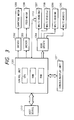
- Fig. 3 is a block diagram showing a control unit of the ink jet recording apparatus shown in Fig. 1.
- a control unit 1201 is mainly constituted by a CPU, a ROM, a RAM, and the like, and controls the respective sections of the apparatus according to a program stored in the ROM.
- a driver 1202 drives a carriage motor 1205 for moving (main-scanning) the carriage 706 in the X-direction on the basis of a signal from the control unit 1201.
- a driver 1203 drives a feed motor 1206 for feeding (sub-scanning) a recording medium in the Y-direction by driving the sheet supply rollers 705 and the sheet feed roller 703 on the basis of a signal from the control unit 1201.
- a driver 1204 drives color multi-heads 1207 to 1210 (corresponding to the heads 702 in Fig. 1) on the basis of print data from the control unit 1201.
- a console/display unit 1211 is used for performing various key inputs and various displays.
- a host device 1212 supplies print data to the control unit 1201.
- a temperature sensor 1213 detects the temperature of the black multi-head 1207.
- the carriage 706 located at the home position in Fig. 1 before a print operation is started performs a print operation for all colors on a record area on the sheet surface using the n multi-nozzles 801 of the multi-heads 702 while being moved forward in the X-direction.
- the carriage starts backward movement toward the home position, and performs a print operation of black data alone.
- the sheet is fed in the Y-direction according to the width of the recording area by rotating the sheet feed roller 703 in the direction of the arrow. In this manner, when the print operation using the multi-heads and the sheet feed operation (sub-scan) are repetitively executed, data is printed on one sheet surface.
- a user upon execution of image recording, a user selects a print mode by manually operating a media selector in the console/display unit 1211 depending on whether a recording sheet is general paper or special-purpose paper such as TP paper (or coated paper).
- TP paper or coated paper
- TP paper has lower absorbency than other recording sheets although it has no feature of blurring unlike in the coated paper, a long time is required until the ink is completely absorbed. Therefore, when the print time per unit area is short like in the bi-directional print mode, boundary blurring between different colors may occur. For this reason, the TP paper is not suitable for a print mode attained by a small number of passes. Therefore, when the coated paper or TP paper is selected by the media selector, a 4-pass one-directional print mode is selected.
- Figs. 4 to 9 show the 2-pass bi-directional print mode as the normal sheet standard mode.
- Figs. 4 to 7 show a state wherein the same thinning masks are used for the black and yellow inks, thinning masks, which compensate for the black and yellow masks, are used for the cyan and magenta inks, and print operations are executed while exchanging these masks in units of passes.
- each multi-head 702 has eight nozzles
- Figs. 4 to 7 show first to fourth scans in which reciprocal print operations and a sheet feed operation by an L/2 width with respect to a head length L are performed, together with the landing orders of pixels.
- the four colors are aligned with respect to the sheet surface in the order shown in Figs. 4 to 7, and are recorded in the landing order according to the head scan direction indicated by an arrow in units of scans.
- Fig. 4 shows the color masks and the ink landing order on the sheet surface in the first scan.
- the color inks are ejected onto an area (1) on the normal sheet using lower half four nozzles of the eight nozzles of each head while scanning the four color multi-heads in the direction of an arrow A by the carriage 706.
- the print operation is performed using masks 401 to 404 corresponding to the four colors, as shown in Fig. 4, and ink dots sequentially land on pixels in the area (1) on the sheet surface, as indicated by reference numeral 405.
- the sheet is fed by L/2 corresponding to the half length of each multi-head in the direction of an arrow C.
- the ink dots land on the pixels on the sheet surface in the order from the left-hand side to the right-hand side.
- the ink dots land on a pixel 418 in the order of K ⁇ Y and the ink dots land on a pixel 419 in the order of C ⁇ M.
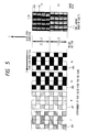
- Fig. 5 shows the color masks and the ink landing order on the sheet surface in the second scan.
- color ink dots are ejected onto areas (1) and (2) on the normal sheet using all the nozzles (eight nozzles) of each head while scanning the four color multi-heads in the direction of an arrow B opposite to the direction of the arrow A by the carriage 706.
- masks 406 to 409 respectively have complementary patterns with respect to the above-mentioned masks 401 to 404 (Fig. 4).
- the ink dots sequentially land on pixels in the area (1), as indicated by reference numeral 410, and the ink dots sequentially land on pixels in the area (2), as indicated by reference numeral 411. Thereafter, the sheet is fed by another L/2 in the direction of the arrow C. With the second scan, the print operation on the area (1) is completed. In the first and second scans, the ink dots land on the pixel 418 in the area (1) in the order of K ⁇ Y ⁇ M ⁇ C, and ink dots land on the pixel 419 in the order of C ⁇ M ⁇ Y ⁇ K.
- Fig. 6 shows the color masks and the ink landing order on the sheet surface in the third scan.
- the color inks are ejected onto areas (2) and (3) on the normal sheet using all the nozzles (eight nozzles) of each head while scanning the four color multi-heads in the direction of the arrow A by the carriage 706.
- the print operation is performed using masks 412 to 415 corresponding to the color inks.
- These masks 412 to 415 respectively have the same arrangement as those obtained by repeating the above-mentioned masks 401 to 404 (Fig. 4) in the sub-scan direction, and complement the masks 406 to 409 (Fig. 5).
- ink dots sequentially land on pixels in the area (2) on the sheet surface, as indicated by reference numeral 416, and ink dots sequentially land on pixels in the area (3), as indicated by reference numeral 417. Thereafter, the sheet is fed by another L/2 in the direction of the arrow C. With the third scan, the print operation on the second area (2) is completed.
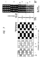
- Fig. 7 shows the color masks and the ink landing order on the sheet surface in the fourth scan.
- the color inks are ejected onto areas (3) and (4) on the sheet surface using all the nozzles (eight nozzles) of each head while scanning the color multi-heads in the direction of the arrow B like in the second scan by the carriage 706.
- the print operation is performed using the same masks 406 to 409 as those in the second scan in correspondence with the colors.
- ink dots sequentially land on pixels in the area (3) on the sheet surface, as indicated by reference numeral 420, and ink dots sequentially land on pixels in the area (4), as indicated by reference numeral 421. Thereafter, the sheet is fed by another L/2 in the direction of the arrow C. With the fourth scan, the print operation on the second area (3) is completed.
- print operations are similarly performed on the areas on the sheet surface.
- the print operation is performed using the upper half four nozzles of each multi-head, thus completing the print operation of one page of the normal sheet.
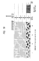
- Fig. 8 shows the printed state of a green image in which color nonuniformity tends to be particularly conspicuous upon execution of the above-mentioned print method.
- thinning masks 501 and 502 are used in correspondence with the passes.
- cyan and yellow dots have landing points on different pixels. More specifically, the cyan mask for the first pass is the same as the yellow pass for the second pass, and the cyan mask for the second pass is the same as the yellow mask for the first pass. That is, complementary masks are exchanged for each pass. Therefore, these two color ink droplets are never simultaneously printed on the same landing point in a single pass.
- landing states 504 and 505 are obtained.
- a capital letter indicates a high-density dot
- a small letter indicates a low-density dot.
- cyan dots land on the sheet surface slightly earlier than the yellow dots.
- the yellow ink droplets land on positions different from the pixel positions where the cyan dots land before the cyan ink droplets are completely absorbed.
- This state corresponds to a state 601 in Fig. 9.
- the yellow ink droplets land on and are absorbed by a blank sheet at substantially an equivalent level to that of the cyan ink, and hence, have substantially the same density as that of the cyan ink droplets in the landing state (504, 602).
- the bi-directional print method Upon execution of the bi-directional print method, it is effective to prevent color nonuniformity by recording ink colors, which may easily cause conspicuous color nonuniformity, in equivalent landing states in units of scans.
- the cyan and yellow inks are printed using different thinning masks. If a mask for printing the cyan and yellow dots on an identical pixel is used, these two colors have unbalanced color tones in the forward and backward scans, and may possibly cause color nonuniformity.
- the cyan and yellow inks have been described. However, in practice, the black and magenta inks are added to these inks. Therefore, at least two of these four inks must not land on an identical pixel in a single pass.
- the color inks can be grouped, so that two colors (e.g., cyan and yellow, or magenta and yellow), which particularly easily cause conspicuous color nonuniformity, use different masks.
- two colors e.g., cyan and yellow, or magenta and yellow
- the 2-pass bi-directional print method is realized using the above-mentioned means, a high-quality image free from color nonuniformity can be formed on the normal sheet to have the same throughput as that obtained by a one-directional 1-pass print method.
- each multi-head 702 consists of 16 nozzles, and Figs. 10 to 14 show first to fifth scans of the print states of this method.
- Fig. 10 shows the relationship between the color masks and image areas on the sheet surface in the first scan.
- the color inks are ejected onto an area (1) on the coated paper or TP paper using four nozzles, located at the most up-stream side with respect to the sheet feed direction, of each head while scanning the four color multi-heads in the direction of an arrow D by the carriage 706.
- the print operation is performed using 25% thinning masks 701 to 704 corresponding to the colors, as shown in Fig. 10.
- the mask 701 is obtained by juxtaposing a mask 705 having a 4 ⁇ 4 pixel area, and a mask 706 obtained by inverting the mask 705 in the main scan direction, and this pattern arrangement is common to all the colors.
- the sheet is fed by a with L/4 corresponding to a 1/4 length of each multi-head.
- Fig. 11 shows the relationship between the color masks and image areas on the sheet surface in the second scan.
- the color inks are ejected onto areas (1) and (2) on the sheet surface using eight nozzles (lower half nozzles), located at the upstream side with respect to the sheet feed direction, of the 16 nozzles of each head, while scanning the four color multi-heads in the direction of the arrow D by the carriage 706.
- the print operation is performed using 25% thinning masks 707 to 710 corresponding to the colors, as shown in Fig. 11.
- the mask 707 is obtained by repeating, in the sub-scan direction, a mask obtained by juxtaposing a mask 711 having a 4 ⁇ 4 pixel area and a mask 712 obtained by inverting the mask in the main scan direction.
- the masks 707 to 710 have complementary dot pattern arrangements with respect to those of the masks 701 to 704. After the print operation on the areas (1) and (2), using these masks, the sheet is fed by another L/4 width.
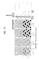
- Fig. 12 shows the relationship between the color masks and image areas on the sheet surface in the third scan.
- the color inks are ejected onto areas (1), (2), and (3) on the sheet surface using 12 nozzles, located at the upstream side with respect to the sheet feed direction, of each head, while scanning the four color multi-heads in the direction of the arrow D by the carriage 706.
- the print operation is performed using 25% thinning masks 713 to 716 corresponding to the colors, as shown in Fig. 12.
- the mask 713 is obtained by repeating, in the sub-scan direction, a mask obtained by juxtaposing a mask 717 having a 4 ⁇ 4 pixel area and a mask 718 obtained by inverting the mask in the main scan direction.
- the masks 713 to 716 have complementary dot pattern arrangements with respect to those of the masks 701 to 704 and the masks 707 to 710. After the print operation on the areas (1), (2), and (3) using these masks, the sheet is fed by another L/4 width.
- Fig. 13 shows the relationship between the color masks and image areas on the sheet surface in the fourth scan.
- the color inks are ejected onto areas (1), (2), (3), and (4) on the sheet surface using all the nozzles (16 nozzles) of each head, while scanning the four color multi-heads in the direction of the arrow D by the carriage 706.
- the print operation is performed using 25% thinning masks 719 to 722 corresponding to the colors, as shown in Fig. 13.
- the mask 719 is obtained by repeating, in the sub-scan direction, a mask obtained by juxtaposing a mask 723 having a 4 ⁇ 4 pixel area and a mask 724 obtained by inverting the mask in the main scan direction.
- the masks 719 to 722 have complementary dot pattern arrangements with respect to those of the masks 701 to 704, the masks 707 to 710, and the masks 713 to 716. After the print operation on the areas (1) to (4) using these masks, the sheet is fed by another L/4 width. With these first to fourth scans, the print operation on the area (1) is completed.
- Fig. 14 shows the relationship between the color masks and image areas on the sheet surface in the fifth scan.
- the color inks are ejected onto areas (2) to (5) on the sheet surface using all the nozzles (16 nozzles) of each head, while scanning the four color multi-heads in the direction of the arrow D by the carriage 706.
- masks 725 to 728 used in this scan are obtained by repeating the masks 701 to 704 used in the first scan in the sub-scan direction.
- the sheet is fed by another L/4 width. Thereafter, print operations are similarly performed on the areas on the sheet surface.
- the print operation is performed on an area (n-2) using 12 nozzles, on the downstream side with respect to the sheet feed direction, of the 16 nozzles of each multi-head, the print operation is performed on an area (n-1) using 8 nozzles (upper half nozzles) on the downstream side with respect to the sheet feed direction, and the print operation is performed on the last area (n) using four nozzles on the most downstream side with respect to the sheet feed direction, thus completing the print operations for one page.
- this print method completes each image area by four one-directional scans per record area using the 25% thinning masks while feeding the sheet by an L/4 width after each scan unlike in the above-mentioned 2-pass bi-directional print method.
- the 4-pass print mode since one area in the main scan direction is printed using four different groups of nozzles, density nonuniformity caused by variations of the nozzles can be eliminated as compared to the two-pass mode, and a smooth, high-quality image can be obtained.
- the four color inks always use the same thinning masks.
- the ink landing order does not cause color nonuniformity since it is not reversed between forward and backward scans unlike in the bi-directional print mode.
- the 25% thinning mask is used in a large, i.e., 4 ⁇ 8 pixel range. This is to obtain an image having higher image quality in a countermeasure against the density nonuniformity caused by nozzle variations, as has been described above in the paragraphs of the prior art.
- dots aligned in the main scan direction are preferably printed while being uniformly distributed to nozzles equal to the number of passes. Therefore, for this purpose, it is preferable to use a mask, which is elongated in the main scan direction, has no periodicity, and is asynchronous with a binarization pattern that normally has periodicity.
- 10 to 14 is obtained by inverting a 4 ⁇ 4 mask in the main scan direction, and has no periodicity in the main scan direction.
- the density nonuniformity caused by nozzle variations can be effectively eliminated as well as color nonuniformity up to a low duty since the mask is elongated in the main scan direction.
- This print mode has an inferior throughput to that of the 2-pass bi-directional print mode as the normal sheet standard mode, but can expect remarkably high image quality. Therefore, even when print operations are performed on the normal sheet, a user may decide to use the 4-pass one-directional print mode to obtain an image having higher quality.
- a user selects, by the media selector, one of the 4-pass one-directional print mode with which a high-quality image is slowly formed in four passes so as to obtain a smooth image on coated paper or TP paper having good color development characteristics or on the normal sheet, and the 2-pass bi-directional print mode with which an image having standard quality is formed on general paper with high throughput, thus obtaining an image having image quality and the throughput required by the user.
- a black emphasis mode can be performed as a lower-order mode in the TP or coated paper print mode (4-pass one-directional print mode) of the first embodiment.
- a dot landing on the TP paper has a smaller size than that of a dot landing on other recording media, and consequently, the density is lowered or a conspicuous line is undesirably formed.
- this defect is outstanding in a black image, and only a black image is normally printed at a duty of 200% as a countermeasure against the above-mentioned defect.
- a black emphasis print mode may often be executed to obtain a clear black image and to obtain high-contrast black characters and ruled lines. Since the necessity of the black emphasis mode varies depending on an image to be printed, a user is allowed to select the black emphasis mode using a mode selector in the console/display unit 1211, as needed, in this embodiment.
- the 4-pass one-directional print mode determines how to execute black emphasis.
- Two print methods are available, and one of these methods is obtained by adding a backward black emphasis scan to the 4-pass one-directional print mode of the first embodiment.
- This method is a reciprocal print method in practice, i.e., is a black emphasis print method that places an importance on the throughput.
- the other method is an 8-pass one-directional scan mode including new black emphasis scans, and is selected when a black head temperature t is higher than a predetermined value T0. This method is designed to prevent an excessive ejection amount due to the temperature rise in the bi-directional print mode and to prevent an image defect caused by the excessive ejection amount.
- Fig. 15 is a flow chart showing these print sequences.
- the normal 4-pass one-directional print mode without black emphasis is represented by a mode A
- a mode including a backward black emphasis scan as one of black emphasis modes is represented by a mode B
- a one-directional print mode including new black emphasis passes to have a total of eight passes is represented by a mode C. Since the print method in the mode A has already been described in the first embodiment, the modes B and C will be described below.
- Figs. 16 and 17 respectively show the print methods in the modes B and C using 16-nozzle heads.
- a unit image area is completed by eight scans.
- Masks used in these modes are the same as those shown in Figs. 10 to 13.
- the C, M, Y, and K dots are printed in each forward scan, and an emphasis print operation of only black dots is performed in the corresponding backward scan using the same thinning mask as that in the forward scan.
- the carriage 706 is returned by an idle print scan, and thereafter, a scan for the black emphasis print operation is performed in the forward direction.
- the mode C requires a longer print time than the mode B by the carriage return time.
- defects such as an excessive ejection amount caused by over-heating of the black head, unbalanced color tones from other color multi-heads, and the like may occur.
- the temperature of the black head is checked based on the output from the temperature sensor 1213 in each scan, and when the temperature falls outside an ejection amount range, in which the above-mentioned image defects may occur, the print operations are performed in the mode B.
- the print method is switched to the mode C from the next scan.
- a print start command when a print start command is input, it is first checked if the current print mode is a black emphasis mode (S100). If it is determined that the current mode is not a black emphasis mode (No in step S100), the control enters the mode A, and the 25% 4-pass one-directional print mode is repeated up to the end of data (S109 to S112). Contrary to this, if it is determined that the current mode is a black emphasis mode (Yes in step S100), a 25% print operation is performed by one scan (S101), and the temperature of the black head is checked without returning the carriage (S102).
- a black emphasis backward print operation is performed (S103).
- the sheet is fed by an L/4 width (S104), thus completing one scan including the BK emphasis operation as the mode B.
- the carriage is returned without performing a print operation so as to prevent a further temperature rise of the head (S105).
- a black emphasis forward print operation is performed (S106), and thereafter, the carriage return operation (S107) and the L/4 sheet feed operation (S104) are performed, thus completing one scan including the black emphasis operation as the mode C. Steps S101 to S107 are repeated up to the end of data (S108).
- the temperature of the black head is checked in the modes B and C in each scan, and the print mode is automatically switched between the modes B and C according to the temperature. Therefore, since the main body automatically switches the print mode in correspondence with an internal print condition, i.e., the temperature rise of the head, a user can obtain a stable image with a throughput as high as possible.
- the head temperature is detected only in the black emphasis mode.
- the print mode may, for example, be switched between the one-directional and bi-directional print modes by detecting the temperatures of the four color heads.
- the head temperature is properly detected, and the print mode is automatically switched between the one-directional and bi-directional print modes according to the detected temperature, thus always obtaining a stable image with a throughput as high as possible.
- the 2-pass bi-directional print mode and the 4-pass one-directional print mode can be selected. Furthermore, a 4-pass bi-directional print mode may be allowed to be selected by the media selector.
- a case will be exemplified below with reference to Fig. 18 wherein a unit image area is completed by four main scans (four passes) by reciprocally scanning the carriage twice.
- each head has 16 nozzles, and a sheet is fed by an L/4 width with respect to a head length L after each main scan.
- these four different masks are used in turn in four passes.
- the same mask is not used for two or more colors in a single scan. More specifically, in Fig. 18, each color selects masks 1301 to 1304 in turn in units of passes.
- this embodiment is an effective means for all the ink colors, as described above, even when any two colors are to be mixed or three-color mixed data is input, the respective color dots can land on the sheet surface under equal conditions, and color nonuniformity can be effectively prevented as well.
- This embodiment is not only effective for the color nonuniformity but also further effective for the density nonuniformity caused by nozzle variations as an original object to be solved by the divisional print method as compared to the first embodiment.
- one dot line in the main scan direction is completed by two nozzles, while in this embodiment, one dot line is completed by four nozzles. For this reason, a smoother image can be obtained.
- a 4 (sub-scan direction) ⁇ 8 (main scan direction) pixel mask may be used, as shown in Figs. 19 to 25.
- dots aligned in the main scan direction are preferably printed while being uniformly distributed to nozzles equal to the number of passes. Therefore, for this purpose, it is preferable to use a mask, which is elongated in the main scan direction, has no periodicity, and is asynchronous with a binarization pattern that normally has periodicity.
- the mask of this embodiment is obtained by juxtaposing the mask shown in Fig. 18 and a mask obtained by inverting the mask shown in Fig. 18 in the main scan direction, and has no periodicity in the main scan direction.
- the density nonuniformity caused by nozzle variations can be effectively eliminated as well as color nonuniformity up to a low duty since the mask is elongated in the main scan direction.
- the thinning masks are selected in consideration of the reciprocal print method based on an equal area gradation method for all the colors, so that two or more dots of one color are not printed on a single pixel in one scan.
- proper thinning masks may be different from each other in units of colors, as has already been described above in the paragraphs of the background of the invention with reference to Figs. 81 to 84 and Figs. 85, 86, and 75.
- the present invention is also effective for a case wherein different thinning masks are formed in accordance with the corresponding area gradation methods for the purpose of preventing color nonuniformity or density nonuniformity caused by nozzle variations even in the one-directional print mode.
- a 4-pass black emphasis bi-directional print mode will be described below. This mode may be further allowed to be selected by the media selector.
- a black emphasis operation particularly required when the inks are printed on, e.g., an OHP sheet, is added to the third embodiment.
- This embodiment has as its object to obtain an image having a high black density with a throughput equal to that of the third embodiment by using a black mask having a different thinning ratio from those of the remaining colors.
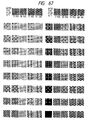
- Fig. 26 shows the print method of this embodiment like in Fig. 8 of the first embodiment and Fig. 18 of the third embodiment.
- the C, M, and Y inks 25% print operations are performed in the respective passes using the same masks at the same timings as those in the third embodiment, and an image having the same quality as that in the third embodiment can be obtained for these three colors.
- the black ink thinning masks 3005 to 3008 are used in correspondence with the passes. These masks are formed especially in consideration of a black-red (RK) color-mixed image. Of three-mixed colors, an RK image using magenta, yellow, and black suffers from particularly conspicuous color nonuniformity.
- RK black-red
- magenta and yellow dots are inhibited from being simultaneously printed on a pixel, where a black dot is printed, in each single pass. More specifically, of masks 3001 to 3004, two masks, which do not simultaneously use M and Y colors for a single pixel position in each pass, are combined to obtain a black mask having a thinning ratio of 50%.
- black dots can land on every pixels at a duty of 200%, and an image having a high black density can be obtained while maintaining the relationship among black, magenta, and yellow to be equivalent to that in the third embodiment.
- patterns 3009 to 3014 represent how to print the print data of an RK image at a duty of 100% under the above-mentioned conditions.
- the pattern 3009 represents RK image data input to a 4 ⁇ 4 pixel area
- the patterns 3010 to 3013 represent the print states of the data 3009 in the first to fourth passes.
- the priority color of each pixel is represented by a capital letter like in the first and third embodiments.
- the pattern 3014 represents the ink landing states on the respective pixels after the print operations are completed.
- the priority color is also represented by a capital letter.
- the 4 ⁇ 4 i.e., 16 pixels, black as a color to be emphasized serves as the priority color, and in the remaining half pixels are equally divided into four each pixels respectively having as their priority colors, magenta and yellow.
- Such an RK image has a higher black density than that obtained when the respective color dots are printed at equal thinning ratios by the method described in, e.g., the third embodiment.
- an image area obtained by printing the pattern 3010 in the first pass has been described.
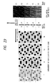
- Cyan print positions in the masks 3001 to 3004 are completely included in the black print positions shown in the masks 3005 to 3008. Therefore, when print data 3101 shown in Fig. 27 is input, print states 3102 to 3105 are attained in the first to fourth passes.
- the color tone of the area is determined by a color, which serves as the priority color in the first pass, as has already been described in the paragraphs of the background of the invention. Therefore, in this case, in a print area started from a forward scan, black completely becomes the priority color, and there are no pixels having cyan as the priority color (3106).
- the combination of the black and cyan does not cause conspicuous color nonuniformity with respect to the visual sense of man.
- the above-mentioned thinning masks are used for preferentially removing the influence of the combinations of yellow and black (YK), and magenta and black (MK), which easily cause conspicuous color nonuniformity.
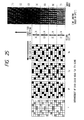
- masks which equally consider color nonuniformity of the respective colors, as shown in, e.g., Fig. 28, may be used.
- the respective colors are equally affected by color nonuniformity, particularly conspicuous color nonuniformity in a black-emphasized high-density image can be prevented.
- patterns 3209 to 3214 represent the print states of K, C, M, and Y images using the above-mentioned masks.
- a print area started from a forward scan and a print area started from a backward scan have different numbers of priority pixels.
- the former area includes eight black pixels, and two each cyan, magenta, and yellow pixels (3214), while the latter print area includes four each black, cyan, magenta, and yellow pixels (3215).
- the area started from the forward scan and the area started from the backward scan have different priority colors, i.e., different color tones, such a different may cause color nonuniformity.
- this method is effective according to the degree of color nonuniformity.
- black dots are always printed at a duty of 50%.
- one print area in the main scan direction is completed by two nozzles per pixel, i.e., a total of four different nozzles in the four passes. Therefore, a high-density image can be obtained while maintaining the effect of preventing nozzle variations to be equivalent to that in the second embodiment.
- the thinning ratio is set to be a duty of 25%
- the thinning ratio of black dots is set to be 75%, so that the number of pixels serving as priority colors can be equally distributed to the respective colors and passes in both the forward and backward scans.
- the black masks having the thinning ratios of 50% (or 25% + 75%), and the C, M, and Y masks having the thinning ratios of 25%, and different in units of colors are used, and the C, M, and Y thinning masks are sequentially used in turn in units of passes, thus obtaining a smooth image free from color nonuniformity and having a high black density in a low time cost state, i.e., in the bi-directional print mode.
- another black emphasis print mode may be further allowed to be selected by the mode selector in addition to the 4-pass one-directional or bi-directional print mode.
- a 1-pass black emphasis print mode will be described below as the fifth embodiment.
- the carriage is returned to the home position without feeding a sheet.
- the black head performs the second ejection on the pixels on which the black dots landed in the forward scan.
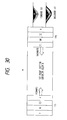
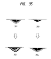
- Fig. 30 shows this print state.
- an RK (magenta, yellow, black) image is printed on all pixels in a predetermined area like in the above embodiment.
- the heads are located at a position 105, and perform print operations on a first print area corresponding to the length of each multi-head while being moved in the direction of an arrow until they reach a position 106.
- the inks land in the order of K, M, and Y, an ink layer 101 on the sheet surface is obtained, and a superior color in this case is black.
- the carriage is moved to the position 105 without feeding the sheet from the position 106. In this scan, only the black head performs a print operation.
- black dots land on the pixels each having the ink layer 101, a landing state 102 is obtained after landing, and a superior color is also black.
- Fig. 31 shows this state.
- the heads stand by at a position 107.
- the inks land on a second print section in the order of K, M, and Y like in the first print section, thereby obtaining an ink layer 103 equal to that of the first print section.
- only the black head performs a print operation from a position 108 in the direction of an arrow.
- an ink layer 104 is obtained, and is equal to that of the first print section. Therefore, a superior color will not be changed in units of print section widths unlike in the prior art described previously.
- a 2-pass black emphasis print mode will be described below as the sixth embodiment.
- the above-mentioned divisional recording method is executed to remove color nonuniformity of the colors caused by nozzle variations in especially a color image, and reciprocal print operations of only black ink is performed to emphasize a black image.
- each multi-head has eight nozzles.
- a case will be exemplified below wherein an RK image is printed at a duty of 100% like in the fifth embodiment.
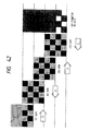
- Fig. 32 shows print states in this mode like in Figs. 30 and 31.
- a print area is completed by a four-nozzle width in each scan using the multi-heads each having eight nozzles.
- states 301, 303, 304, and 306 nozzles painted in black indicate those used in the print operations.
- the multi-heads stand by at a position 301 in the sub-scan direction with respect to a sheet surface 302.
- the K, M, and Y heads perform print operations on gray pixels on the sheet surface 302 using the corresponding nozzles while being scanned in the direction of an arrow.
- the inks are printed on one landing point in the order of K, M, and Y.
- a pixel having an ink layer and a pixel on which no ink lands are alternately aligned at neighboring positions. Since the ejection amount of one dot, which lands on the sheet surface at this time, is designed to extend beyond one pixel, the dot permeates to the neighboring pixel position, and almost forms the first layer of the neighboring pixel.
- each ink layer in the first print area has a state 402 in Fig. 33.
- the third scan is performed.
- a sheet is fed by a distance corresponding to four nozzles (1/2 the total number of nozzles), and the multi-heads stand by at the left side on the sheet surface and at a position 304 in the sub-scan direction.
- the heads perform print operations in the order of K, M, and Y on gray pixels on a sheet surface 305 while being scanned in the direction of the arrow like in the first scan.
- pixels to be printed include the remaining pixels on the first print area, which are not printed in the first scan, and half pixels on a blank second print area.
- the first and second print areas have ink landing states 403 in Fig. 33.
- the second print area has the same ink landing state as that on the first print area after the first scan.
- the sheet surface section has a state 404 in Fig. 33, and the print operations on the first print area are completed in the illustrated state.
- the second print area has the same state as that after the second scan of the first print area is completed, and thereafter, the same print scans as described above are repeated twice to obtain the same landing state of the ink layer as that on the first print area. Therefore, on the first and second print areas, a smooth image can be obtained by the divisional print method without causing color nonuniformity, which may occur in the bi-directional print mode.
- the sixth embodiment is further extended, and is characterized in that every time the forward and backward print scans of the sixth embodiment are executed, a sheet is fed by a distance corresponding to 1/4 the total number of nozzles.
- This embodiment uses masks different from those in the sixth embodiment. With this method, the black emphasis divisional print method can be further improved while maintaining almost the same throughput as in the sixth embodiment, and a smooth image in which density nonuniformity caused by nozzle variations are further reduced can be obtained.
- Figs. 34(a) to 34(g) show print states in this mode like in Fig. 32.
- each multi-head has eight nozzles.
- a print area is completed in units of 1/4 widths of eight nozzles, i.e., 2-nozzle widths in each scan.
- nozzles painted in black indicate those used in the print operations.
- the multi-heads stand by at a position 1101 in the sub-scan direction with respect to a sheet surface 1102.
- the K, M, and Y heads perform print operations on gray pixels on the sheet surface 1102 using the corresponding nozzles while being scanned in the direction of an arrow.
- inks land on one landing point in the order of K, M, and Y, and form ink layers 201 shown in Fig. 35.
- ink landing pixels half a total number of pixels in this area and the remaining non-landing pixels are mixed like in the sixth embodiment.
- a sheet Prior to the second scan, a sheet is fed by a width corresponding to two nozzles, and the heads and the sheet surface have the positional relationship of the second scan, as shown in Fig. 34(b).
- Only the black head performs a print operation from a position 1103 in the opposite direction by a width (four-nozzle width) of a Bk second print area.
- black dots land on black-painted pixels which have already been subjected to printing in the first scan in the 2-nozzle width overlapping the print area of the first scan (forward scan), and hatched pixels about half a total number of pixels in the remaining two-nozzle width area.
- the third scan is performed.
- the sheet is fed by another 2-nozzle width, and the multi-heads stand by at a position 1104 on the left side of the sheet surface, as shown in Fig. 34(c).
- the heads perform print operations on gray pixels on the sheet surface in the order of K, M, and Y like in the first scan while being scanned in the direction of the arrow.
- ink dots land on the remaining non-printed pixels on the color first print area, and pixels half a total number of pixels on the color second print area, as indicated by gray pixels in Fig. 34(c).
- the fifth scan is similarly performed from a position 1106 shown in Fig. 34E, and the print operation on the next 2-nozzle width area is completed, as shown in Fig. 34(e).
- this area includes pixels on which the black dots landed first in the second scan, and K, M, and Y dots landed in the fifth scan, and pixels on which K, M, and Y dots landed in the third scan, and thereafter, black dots landed in the fourth scan, half by half.
- Each of the former pixels has ink layers 204 in Fig. 35, and each of the latter pixels has ink layers 202 in Fig. 35. Both the layers have black first layers serving as a superior color although they have different second black layer positions as an emphasized color.
- the color tone varies depending on the ink landing order.
- the color tone is controlled by the first layer, i.e., the first landing ink color. Therefore, the second and subsequent ink landing layers do not always form complete layers shown in Fig. 35 in practice, and the colors are mixed. For this reason, the colors of the second and subsequent layers hardly influence the color tone on the sheet surface portion. Therefore, almost no color tone difference is observed from the ink layers 202 and 204 shown in Fig. 35, and these layers do not cause color nonuniformity.
- the thinning masks in units of pixels are used.
- the above-mentioned divisional recording method may be executed using thinning masks in units of m ⁇ n (m and n are positive integers and at least one of them is equal to or larger than 2) pixel groups.
- Figs. 36 and 37 best illustrate the present invention in comparison with Fig. 76, and show ink landing states after the first scan in a certain area like in Fig. 76.
- dots recorded in a single scan land on alternate non-neighboring pixel positions (Fig. 76).
- all pixels are grouped into 4 ⁇ 3 groups (Fig. 36) or 4 ⁇ 4 groups (Fig. 37), so that dots on pixels in a single pixel group are recorded in a single pass, and the pixel groups are recorded at non-neighboring positions in a single pass. In this manner, as can be seen from Figs.
- Fig. 38 shows a recording state of this embodiment to be compared with the prior art shown in Fig. 78.
- a head consisting of 16 nozzles is used, and bi-directional print operations are executed while feeding a sheet by an 8-nozzle width.
- Data to be recorded in this case is a 100% green image consisting of cyan and yellow.
- Fig. 38 exemplifies a case wherein dots each having a dot size of 110 ⁇ m are recorded at a pixel density of 360 dpi.
- dots are printed on first and second areas on the recording medium according to a divisional thinning pattern 4002 using all the nozzles of the Y and C multi-heads 702.
- the pattern 4002 complements the pattern 4001.
- ink dots are ejected in the order of Y ⁇ C onto areas on the recording medium, which correspond to pixel groups painted in black in the pattern 4002.
- the sheet feed operation is performed by a distance according to the length half (eight nozzles) the multi-head.
- the third scan by moving the carriage forward, dots are printed on second and third areas on the recording medium according to a divisional thinning pattern 4003 using all the nozzles of the Y and C multi-heads 702.
- the pattern 4003 has the same arrangement as that of the pattern 4001, and complements the pattern 4002.
- ink dots are ejected in the order of C ⁇ Y onto areas on the recording medium, which correspond to pixel groups painted in black in the pattern 4003.
- the sheet feed operation is performed by a distance according to the length of eight nozzles.
- dots are printed on third and fourth areas on the recording medium according to a divisional thinning pattern 4004 using all the nozzles of the Y and C multi-heads.
- the pattern 4004 has the same arrangement as that of the pattern 4002, and complements the pattern 4003.
- ink dots are ejected in the order of Y ⁇ C onto areas on the recording medium, which correspond to pixel groups painted in black in the pattern 4004.
- the sheet feed operation is performed by another 8-nozzle distance.
- the mask in units of 4 ⁇ 3 dot groups is used as a thinning mask.
- the proper values of m and n vary depending on conditions such as a pixel density, an ink ejection amount, a recording medium, or the like given for each case. If m and n are too small under the above conditions, the effect of this embodiment cannot be obtained. Conversely, if a dot group is as large as one resolved by human eye, a color tone difference between neighboring groups is sensed, and a coarse image is formed.
- Fig. 40 is a table showing the extrusion rate obtained when divisional recording is performed using a rectangular thinning mask in units of n ⁇ m pixel groups with respect to the ratio of the dot size to a predetermined pixel pitch, and a color distance (or difference) between record areas with respect to each extrusion rate.
- the extrusion rate indicates the rate of extrusion of dots recorded in the first scan to a non-print area to be subjected to recording in the second scan.
- the color distance between record areas indicates a color distance between neighboring record areas obtained when a green image consisting of cyan and yellow is divisionally recorded like in Figs. 38, 39, and 78, in correspondence with the extrusion rate.
- the extrusion rate is decreased as the number of dots in a dot group is increased. If the number of pixels (the number of dots) remains the same, the extrusion rate is decreased as the pixels define a shape closer to a square.
- a real color distance corresponding to each extrusion rate is a measurement value obtained by real recording and a color distance meter. Furthermore, a theoretical color distance is calculated from spectrum distributions of two different reference green images in correspondence with the extrusion rate.
- the CMC color distance used here is the latest method of various color distance formulas, which method is designed to cause a color distance obtained from the normally used CIE 1976 (L*a*b*) color distance formula to further approach a visual color distance of man.
- each attribute can be visually independently evaluated, and a countermeasure (weighting) can be easily taken in accordance with each attribute.
- formulas for obtaining the correction coefficients the following formulas are obtained as a result of statistic examinations (Yukio Murata, "Handbook of Color Techniques", K.K.
- the theoretical color distance and the corresponding real color distance always have a small difference therebetween. This difference is caused since the theoretical color difference is calculated by the perfect additive color mixing of two different green images in the process 2 in the above description.
- the additive color mixing is a method wherein colors (spectrum distributions) of a plurality of non-overlapping small regions present in a unit region are added to each other according to the ratio of areas of the small regions, and the sum spectrum distribution is set as a color of the unit region.
- a subsequently recorded dot extends under the previously recorded dot, and the theoretical color distance of a dot-overlapping area is calculated based on the previously recorded dot color alone.
- the tone color of the overlapping portion of two different color dots is not always completely controlled by only the tone color of the previously recorded.
- the color tone of the subsequently recorded dot should be added to the tone color of the overlapping area by subtractive color mixing although it influences the color tone only slightly. Therefore, the calculated theoretical color distances of areas are always larger than corresponding real color distances.
- a proper size of a mask can be estimated by a calculation even when different inks or recording media are used.
- a critical color distance between colors which are perceived as equal colors by the normal visual sense of man, is about 1.0 to 1.8.
- two different colors having a color distance therebetween larger than the above-mentioned value are located at neighboring positions, a boundary is observed between these colors, and the two colors are sensed as different areas.
- the above-mentioned critical color distance region is indicated by two stages of boundary lines.
- the extrusion rate corresponding to the critical color distance is about 25% to 33%. More specifically, a condition for preventing color nonuniformity is that the extrusion amount of each ink dot to a non-print area becomes 1/3 and more preferably 1/4 or less the pixel width.
- a dot size of 110 ⁇ m is used with respect to a pixel density of 360 dpi, and a thinning mask in units of 4 ⁇ 3 pixel groups is used.
- the ratio of the dot size to the pixel density is about 1.5
- the extrusion rate is 21.98%
- the theoretical and real color distances are respectively 1.25 and 1.20.
- This embodiment is also effective for time distance nonuniformity or rest nonuniformity observed in a monochrome image.
- the time distance nonuniformity is observed when a dot in the second pass is recorded on an area where a dot in the first pass extrudes and is blurred. Therefore, when the dots in the first pass are located adjacent to each other, and the extrusion rate is decreased like in this embodiment, the 2-pass recording method can be executed under substantially the same condition as the 1-pass recording method, and factors which depend on a time distance generated upon overlapping of dots can be eliminated.
- the mask when the mask is unnecessarily large, the color distance between adjacent dot groups in a single print area begins to be observable, an image is roughened, and image quality tends to deteriorate.
- the mask size is about 0.2 mm, an image is slightly roughened, and when it exceeds 0.5 mm, a defect on the image is observed.
- the mask since the 4 ⁇ 3 dot group is used with respect to 360 dpi, the mask has a size of 0.28 mm (sub-scan direction) ⁇ 0.21 mm (main scan direction), and sufficiently satisfies the above conditions.
- a smooth image free from color nonuniformity, time distance nonuniformity, and rest nonuniformity can be obtained in the bi-directional print mode.
- patterns 1701 and 1702 record pixels respectively allowed in the first and second scans of the conventional divisional recording method are indicated by black dots.
- patterns 1703 and 1704 show record pixels according to the divisional recording method of this embodiment.
- a print operation is completed by one scan alone up to 8/16, i.e., a duty of 50%.
- a duty of 50% Even after the duty exceeds 50%, the numbers of record pixels in two passes are largely unbalanced, and the two passes have the same numbers of pixels only when the duty reaches 100%.
- data for one pixel width in the main scan direction of the head are recorded by the same nozzle, and the original object of the divisional recording method cannot be achieved at all, i.e., density nonuniformity caused by nozzle variations cannot be removed.
- the numbers of record pixels in the first and second scans are still unbalanced even in a high-duty area where duty exceeds 50% (8/16), and as compared to this embodiment wherein the numbers of record pixels in two scans are equalized at any duty, an image is expected to deteriorate in terms of the density nonuniformity.
- This problem is posed not only in the bi-directional print mode but also in the one-directional print mode.
- color nonuniformity caused by the ink landing order described in the prior art occurs in addition to the density nonuniformity.
- This problem is a phenomenon which also occurs in the one-directional print mode like the density nonuniformity caused by nozzle variations, and can be solved as long as the same numbers of record pixels are equally distributed to the two passes.
- the thinning mask in units of 4 ⁇ 3 dot groups of this embodiment is used, the number of dots is equally divided into two scans. Therefore, the color nonuniformity can be prevented. Also, since dots aligned in the main scan direction are recorded by two scans, i.e., two different nozzles, this embodiment is effective for the density nonuniformity caused by nozzle variations.
- the 4 ⁇ 3 dot groups are used as the thinning mask in the ink jet recording apparatus for recording dots each having a dot size of about 110 ⁇ m at a recording density of 360 dpi, a smooth, high-quality image free from color nonuniformity, time distance nonuniformity, rest nonuniformity, and nozzle nonuniformity can be obtained.
- a thinning mask in units of 4 ⁇ 4 dot groups as the second pattern of this embodiment will be described below.
- the mask in units of 4 ⁇ 4 dot groups can eliminate the color distance more satisfactorily than the above-mentioned thinning mask in units of 4 ⁇ 3 pixel groups. Since the number of pixels in the mask is increased, the roughness of an image tends to be slightly worsened. However, since the mask size is about 0.28 mm ⁇ 0.28 mm; the above-mentioned roughness is not observed as an image defect.
- Fig. 39 shows the divisional recording state using this mask.
- the recording operation in this case is the same as that in Fig. 38, and a detailed description thereof will be omitted.
- Fig. 42 shows states of time distance nonuniformity and rest nonuniformity for the purpose of comparison with Figs. 41 and 43.
- Fig. 42 using the mask in units of 4 ⁇ 4 dot groups has the smallest overlapping portion, and is most effective for time distance nonuniformity and rest nonuniformity.
- Fig. 45 shows pixel positions recorded in two scans like in Fig. 44 when data binarized by the dither method is divisionally recorded using the mask in units of 4 ⁇ 4 dot groups.
- the same effect obtained by the above-mentioned mask in units of 4 ⁇ 3 dot groups can be obtained for color nonuniformity caused by the unbalanced numbers of recorded dots in the two scans.
- the effect for density nonuniformity caused by nozzle variations is slightly different.
- the mask having four pixels in the main scan direction is used, dots aligned in the main scan direction are always equally divided into two scans.
- the mask in units of 4 ⁇ 4 dot groups is often effective in this respect not only for the Bayer type method shown in Fig. 45 but also for other dither methods. This is for the following reason.
- a unique pixel arrangement is determined by each method (not limited to the Bayer method) in a predetermined (e.g., 4 ⁇ 4 or 8 ⁇ 8) square area in correspondence with the duty.
- a predetermined e.g. 4 ⁇ 4 or 8 ⁇ 8 square area in correspondence with the duty.
- a 4 ⁇ 4 matrix is often used as a submatrix, and the submatrices are two-dimensionally juxtaposed two by two, as shown in Fig. 45.
- This matrix is used for realizing area gradation therein, and is designed to always output an equal pixel arrangement if equal data is input.
- Fig. 45 pixel arrangements shown at the left end of Fig.
- the matrix or submatrix is entirely included in 4 ⁇ 4 dot groups, and neighboring matrices or submatrices can be prevented from being recorded in a single record scan. Therefore, since the same number of recording data having equal arrangements are input to respective matrices for image data at any duty, the numbers of dots in units of record scans have no difference therebetween. In this respect, this method is effective for various binarization methods.
- the two different thinning masks have been introduced as the eighth embodiment.
- various factors such as the relationship between the extrusion rate and color nonuniformity shown in Fig. 40, the ink landing state on a recording medium, a binarization correspondence state, and the like must be considered.
- the shape of the mask the above-mentioned square mask such as a 4 ⁇ 4 mask may be used, or the rectangular mask such as a 4 ⁇ 3 mask may be used.
- the square mask is most effective for color uniformity among mask shapes including a predetermined number of pixels.
- the mask having a four-pixel width in the main scan direction is particularly effective for the binarization methods.
- the thinning mask having a 3-pixel width in the main scan direction is asynchronous with the period of a unit matrix, normally having a 2 n period, for gradation expression, and can always record pixels using two different nozzles at any duty.
- the thinning mask may have various numbers of pixels in the sub-scan direction.
- the number of nozzles of the recording head In order to realize the effect of the calculated extrusion rate on the entire area, and to equalize connection portions in units of scans to other portions, the number of nozzles of the recording head must always be dividable by the number of pixels in the sub-scan direction.
- the number of pixels is set to have an upper limit. Since the present invention cannot be achieved unless at least two pixel groups are present in eight nozzles, a maximum of four pixels are determined as an upper limit.
- various patterns including various numbers of pixels in the main scan direction, various numbers of pixels in the sub-scan direction, various total numbers of pixels in masks, and various mask shapes are available according to recording conditions and various requirements.
- the present invention since the present invention has as its principal object to remove defects in reciprocal recording such as color nonuniformity, time difference nonuniformity, and the like, all the colors need not always use equal arrangements of record pixel groups. As will be described later in the ninth and 10th embodiments, the different mask patterns are rather often effective for the color nonuniformity since a difference between first and second recording inks can be eliminated. However, such a recording method causes a defect in the above-mentioned patent since it causes blurring between different colors.
- the above-mentioned patent describes that a special image system for realizing the effect is installed in either one of a software program or printer firmware.
- a pixel group consisting of m ⁇ n pixels is set as a pseudo pixel called a super pixel so as to perform multi-color expression.
- a dot arrangement to be recorded in each super pixel one of a plurality of predetermined color expression arrangements is selected according to an expression color requested by a number for one pseudo pixel. Therefore, the above patent discloses as one effect that "print quality can be improved without unnecessarily complicating an operation for creating a computer program for forming a large number of colors”.
- pixels in an (m ⁇ n) pixel group of the present invention have no relationship associated with an image such as formation of a pseudo pixel. These pixels are not related to each other and are completely independent from each other, except that they are recorded at the same recording timing.
- a unit matrix in binary gradation expression is completely included in the 4 ⁇ 4 pixel groups.
- the present invention does not require any special image processing system described in the above patent to a host side or a recording apparatus main body.
- the present invention is not particularly limited to a multi-color image, and is sufficiently effective for a monochrome image since it can remove time distance nonuniformity and rest nonuniformity. From the above description, we consider that the present invention is different from the above-mentioned patent.
- a dot group consisting of m ⁇ n pixels such as a rectangular pattern consisting of 4 ⁇ 3 pixels or a square pattern consisting of 4 ⁇ 4 pixels is defined as a unit of a thinning mask, and the thinning mask is set to have a two-dimensional arrangement of the dot groups arranged at alternate non-neighboring positions, a high-quality, smooth image free from defects such as color nonuniformity, time distance nonuniformity, rest nonuniformity, and nozzle nonuniformity can be obtained in the multi-color and monochrome directional and one-directional print modes.
- the ninth embodiment of the present invention will be described below.
- This embodiment is characterized in that different thinning masks in units of 4 ⁇ 4 dot groups are used in correspondence with colors.
- image defects to be particularly solved by the present invention color nonuniformity caused depending on the color ink landing order, and time distance nonuniformity and rest nonuniformity caused by a variation in time between adjacent scans have been described.
- the most conspicuous defect is the former color nonuniformity.
- This embodiment particularly places an importance on this color nonuniformity, and is established to positively solve this defect.
- the four color heads are aligned in a direction equal to the carriage scan direction. Since such an arrangement is adopted, the respective scans inevitably have different recording orders among colors.
- the eighth embodiment described above is designed to perform these two scans under conditions as equal as possible.
- this embodiment has as its object to minimize a difference between priority colors among colors, and in order to achieve this object, checker masks are reversed in a combination of two colors, which easily cause conspicuous color nonuniformity.
- Fig. 46 shows states wherein recording is performed while exchanging, after each scan, cyan and yellow thinning masks, in each of which a 4 ⁇ 4 dot group is defined as a unit matrix, and neighboring matrices are thinned out in a checker pattern.
- a 4 ⁇ 4 dot group is defined as a unit matrix
- the masks are set to record all pixel groups of each area in the first scan, time distance nonuniformity caused by a time distance between the first and second scans is slightly worsened. Therefore, when the time distance nonuniformity is conspicuous, the method of the eighth embodiment is more effective, and this embodiment is effective for a case wherein color nonuniformity is conspicuous in a combination of specific two colors.
- a 4-pass reciprocal recording method will be described below as the 10th embodiment of the present invention.
- This embodiment uses masks in units of 4 ⁇ 4 dot groups as well, and is characterized in that a sheet feed operation is performed by a 1/4 print width between two adjacent scans upon recording of a predetermined area in four scans, and masks are exchanged in turn among colors in units of scans.
- Fig. 47 shows this state.
- one square pattern unit includes a 4 ⁇ 4 pixel group, each head consists of 16 nozzles, and a sheet feed operation is performed by a 4-nozzle width after each scan.
- 4 ⁇ 4 masks which do not overlap each other are cyclically exchanged among colors.
- This embodiment for executing the 4-pass print method is effective for the above-mentioned time distance nonuniformity.
- the print timing varies in units of sheet feed widths, and these different timings appear as time distance nonuniformity, thus causing an image defect.
- the 4-pass print method like in this embodiment, since all areas are recorded by four forward and backward scans, print pixels recorded at a plurality of recording timings are present in each area, and hence, each area is not characterized by the record scan timing.
- this embodiment is more effective not only for the time distance nonuniformity but also for density nonuniformity caused by nozzle variations as an original object to be solved by the divisional recording method than the above embodiment. This is because in the above embodiment, given color dots aligned in the main scan direction are printed by two nozzles, while in this embodiment, such color dots are printed by four nozzles, thus obtaining a smoother image.
- the arrangement of the main body is the same as that shown in Fig. 1, except for a recording head.
- recording nozzles for four colors are aligned in an equal direction in the order of black, cyan, magenta, and yellow, as shown in Fig. 48.
- Fig. 49 shows a recording state when the present invention is applied to the above-mentioned recording apparatus. After each scan, a sheet feed operation is performed by a width corresponding to half the total number of nozzles for one color, and a unit area is completed by eight scans.
- this recording apparatus performs bi-directional recording, when the head has the above-mentioned arrangement, color nonuniformity will not be caused by the ink landing order.
- the present invention can sufficiently exhibit its effects, i.e., an effect of removing time distance nonuniformity, an effect for nozzle nonuniformity by using thinning masks in units of 4 ⁇ 4 dot matrices described in the eighth embodiment.
- four color nozzle groups are arranged to have no gaps for the sake of simplicity. Even when a gap corresponding to a predetermined number of pixels is formed between two adjacent nozzle groups for the purpose of convenience of the nozzle arrangement, the same print method can be applied.
- Fig. 50 shows a print state obtained when a recording method of this embodiment is executed using heads each having 32 nozzles.
- a 1 ⁇ 4 pixel group for simultaneously recording four successive dots in the main scan direction is defined as one unit, and a small rectangle shown in Fig. 50 represents one pixel group.
- Each recording head having 32 nozzles is divided into four record sections each consisting of eight nozzles, and the nozzles in each section perform recording according to a mask shown at the left end of Fig. 50.
- pixel groups allowed to perform recording are pained in black, and the nozzles in each section repetitively perform print operations in the head main scan direction according to a mask having four pixel groups (16 pixels) as one period.
- Fig. 50 shows recording states of the first to fifth scans in corresponding image areas, and represents pixel groups simultaneously recorded in each record scan by equal patterns. Referring to Fig. 50, in the first scan, pixel groups are recorded in a first image area to be joined in an oblique direction according to the mask of the first record section, and a sheet is then fed by one record section. Thereafter, the second scan is executed.
- pixel groups are recorded to be stacked above the pixel groups recorded in the first scan, and in a second image area, pixel groups are recorded according to the mask of the first record section.
- pixel groups are recorded to be stacked above those recorded in the second scan, and in the second and third image areas, pixel groups are recorded according to the masks of the corresponding record sections.
- the recording operations are similarly performed in the subsequent fourth and fifth scans.
- the first and second image areas are completed. In this manner, in each image area, pixel groups are recorded first in the oblique direction, and based on these pixel groups, other pixel groups are always recorded to be stacked above these pixel groups in the subsequent record scans.
- FIG. 51 is an enlarged view of a complete image after the fifth scan in Fig. 50.
- the ink drawing force always acts downward toward a pixel group recorded first by the first record section in each scan. Therefore, a portion where a connection line appears at the highest frequency is considered as a boundary indicated by a bold line between the pixel group recorded first by the first record section and the pixel group recorded last by the fourth record section, and this boundary appears stepwise in units of four pixels, as shown in Fig.
- connection lines indicated by main scan thin lines in Fig. 51 can be eliminated.
- the connection lines in the oblique direction are strong but small, and a plurality of lines appear at small pitches in each image area. Therefore, such connection lines are not almost sensed by the normal visual sense of man, and a smooth, high-quality image can be realized.
- connection line formed on the coated paper is a phenomenon occurring between dots overlaid in different record scans, and tends to appear when the time interval between two record scans is large. Therefore, on the coated paper, a high-density portion (connection line) appears on bold line portions in Fig. 51. Since a plurality of oblique connection lines appear in a direction different from a connection line, sheet feed connection lines can also be eliminated on the coated paper. When rest nonuniformity is to be especially prevented, it is effective to increase the size of the 1 ⁇ 4 pixel group used as the divisional record pixel group in this embodiment.
- a mask arrangement in which pixel groups recorded upon completion of the record scan by the second record section are arranged at non-neighboring alternate positions may be adopted.
- the masks of the second and third record sections shown in Fig. 50 are exchanged.
- the effect of removing the connection portion is slightly reduced.
- TP paper suffers from a beading phenomenon described previously with reference to Fig. 90, and this phenomenon is caused when ink dots, which draw each other, contact before they are completely absorbed.
- pixel groups are preferably completed in a distributed state, as shown in Fig. 52.
- this method is effective for preventing beading when the ejection amount per dot is large or when the pixel density is high even if the ejection amount remains the same.
- This embodiment has been described as a means effective for both a monochrome image and a color image by using fixed masks in correspondence with the record sections.
- different thinning masks may be used in units of colors.
- this embodiment is particularly effective for, e.g., TP paper when serious beading occurs.
- coated paper or general paper since a plurality of color inks are divisionally recorded a plurality of number of times, the densities of mixed colors can be increased.
- black dots may be recorded, in a backward scan, on pixels which have been recorded in a forward scan.
- the recording head having 32 nozzles is divided into four record sections each consisting of eight nozzles, and the 4-pass print method has been described.
- This embodiment is also effective for various other heads as long as they have nozzles which can be equally divided into four record sections.
- the nozzles are divided into four sections each consisting of 16 nozzles, and a record mask in each record section may be obtained by repeating the mask shown in Fig. 50 or 52 twice in the main scan direction in units of record sections. With this arrangement, the same effect as in this embodiment can be expected.
- this patent describes a recording method using equal arrangement methods for all colors, and has as its object to accurately express a gradation level or color tone determined in each group.
- two pixels in each dot group have no relationship therebetween as an image, and are means for merely determining the print order.
- the mask in each record section defines a plurality of pixel groups joined in the oblique directions in units of 1 ⁇ 4 pixel groups as divisional record pixel groups, and in the last record scan corresponding to the fourth pass of each image area, at least two divisional record pixel groups have already been completed at neighboring positions below each of all pixel groups to be recorded in this scan, thereby locally forming strong connection lines below these pixel groups, and eliminating sheet feed connection lines appearing in units of record section widths.
- the 13th embodiment of the present invention will be described below.
- the 4-pass divisional recording method is to be executed, and a 2 ⁇ 4 pixel group including two pixels in the sub-scan direction is used as the divisional record pixel group.
- bi-directional record scans are executed to increase the print throughput.
- Fig. 53 shows the recording state of this embodiment.
- An image is sequentially completed using fixed masks in record sections represented by first to fifth scans like in the 12th embodiment.
- odd-number scans correspond to forward scans
- even-number scans correspond to backward scans.
- the use of such large pixel groups helps to prevent rest nonuniformity on coated paper and general paper.
- the large pixel groups can also prevent a color nonuniformity phenomenon unique to the bi-directional print mode in addition to the rest nonuniformity.
- the color nonuniformity will be briefly described below.
- the bi-directional print mode is an effective means for increasing the throughput.
- the ink landing order on a sheet surface is inevitably reversed between the forward and backward scans in association with the head arrangement. That is, the inks are printed in the order of black, cyan, magenta, and yellow in the forward scan, while the inks are printed in the order opposite to that described above in the backward scan.
- Such a difference between the ink landing orders causes the following image defect.
- Figs. 54A and 54B show the principle of color nonuniformity.
- Figs. 54A and 54B exemplify a case wherein a green image obtained by mixing cyan and yellow is to be recorded by the conventional divisional recording method. Since the first scan is a forward print scan, ink dots land on a single pixel in the order of cyan and yellow. In this case, it is confirmed that the first recorded ink dot remains on the sheet surface portion, while the second landing ink dot sinks below the first dot in the direction perpendicular to the sheet surface. This phenomenon most typically appears on coated paper having a high absorption speed, and a similar tendency is observed more or less on general paper, TP paper, and the like. Therefore, pixels printed in the forward print scan form a cyanish green image, and pixels printed in the backward print scan form a yellowish green image. For this reason, the green images having different color tones are formed in the forward and backward scans (Fig. 54A).
- pixels having these two color tones are arranged half by half.
- each dot size is designed to extrude to the neighboring pixel positions
- pixels to be recorded in the second scan are filled with already recorded extruding dots, and the strongest color tone in each image area is consequently determined by an ink color recorded first in the first scan (Fig. 54B).
- FIGs. 55A to 55C show arrangement (distribution) states of green dots having two different color tones obtained when 4-pass divisional recording is executed while changing the size of the divisional pixel group.
- the divisional record pixel group consists of one pixel alone
- the pixel group consists of 1 ⁇ 4 pixels like in the 12th embodiment
- the pixel group consists of 2 ⁇ 4 pixels of this embodiment.
- the number of yellowish areas printed in the backward print scans is increased to some extent as compared to the divisional print mode in units of dots (Fig. 55A).
- no pixel groups extending in the main scan direction can provide an effect for preventing ink extrusion in the sub-scan direction.
- a unit pixel group including two successive pixels in the sub-scan direction is used as the divisional record pixel group. Therefore, as shown in Fig. 55C, in this embodiment, even when the bi-directional print mode is executed, the color tones in the forward and backward scans can be almost equalized, and an image free from color nonuniformity can be obtained.
- the size of the divisional record pixel group is increased as compared to the 12th embodiment, and the bi-directional print mode is executed.
- an effect for removing connection lines obtained in this embodiment is substantially the same as that obtained by the 12th embodiment.
- the bi-directional print mode can be realized using the 2 ⁇ 4 divisional record pixel groups, as shown in Fig. 53, the method of this embodiment is more preferable in terms of the throughput.
- the size of the divisional record pixel group is set to be as large as possible so as to prevent color nonuniformity among image areas.
- the size of the pixel group is too large, color nonuniformity in units of pixel groups tends to become conspicuous in turn, and especially on coated paper, an image is roughened.
- TP paper since the number of ink dots to be simultaneously printed is increased, the beading phenomenon is worsened, and an image is deteriorated as well. Therefore, it is preferable to set the size of the divisional record pixel group according to recording conditions on each recording medium.
- Fig. 56 is a flow chart showing a print mode switching routine when such a system is introduced.
- a print control method is switched according to the types of recording media, and in particular, for TP paper, two modes are prepared depending on whether or not a black emphasis print is performed.
- a bi-directional print mode using large divisional record pixel groups each consisting of 2 ⁇ 4 pixels is selected to increase the throughput.
- a one-directional print mode using 1 ⁇ 4 divisional record pixel groups is normally selected, and when a user wants to emphasis black, print control for recording only black dots in backward scans is also available.
- a one-directional print mode using 2 ⁇ 4 divisional record pixel groups is selected since it is particularly advantageous for rest nonuniformity.
- the mask in each record section defines a plurality of pixel groups joined in the oblique directions in units of 2 ⁇ 4 pixel groups as divisional record pixel groups, and in the last record scan corresponding to the fourth pass of each image area, at least two divisional record pixel groups have already been completed at neighboring positions below each of all pixel groups to be recorded in this scan, thereby locally forming strong connection lines below these pixel groups, and eliminating sheet feed connection lines appearing in units of record section widths.
- Fig. 57 shows the print state of this embodiment like in the 12th and 13th embodiments.
- a recording head having 27 nozzles is used, and is equally divided into three sections each consisting of nine nozzles.
- the throughput can be increased as compared to the 12th and 13th embodiments.
- Fig. 50 or 53 only an image corresponding to an 8-nozzle width is completed upon completion of the fourth scan, while in this embodiment, an image corresponding to an 18-nozzle width is completed. Therefore, this embodiment can increase the throughput twice those in the 12th and 13th embodiment.
- bi-directional print scans may be executed like in the 13th embodiment, and in this case, the throughput can be almost doubled.
- the effect of this embodiment can be achieved even when a 32-nozzle head used in the 12th or 13th embodiment is used as long as the number of nozzles to be used is selected in correspondence with this embodiment.
- the 1 ⁇ 2 divisional record pixel group which is shorter than that in the above embodiments in the horizontal direction (main scan direction of the recording head), is used.
- Such a small pixel group can provide a more satisfactory effect for preventing beading on TP paper or texture on coated paper although it has a small effect for preventing rest nonuniformity on coated paper or general paper or for color nonuniformity in the bi-directional print mode.
- a table shown in Fig. 58 shows estimation results of quality of connection lines when dots are recorded on TP paper while the number of record divisions is set to be 2 and 3, and the divisional record pixel group size is changed from 1 ⁇ 1 to 1 ⁇ 4.
- the number of record divisions requires to be at least 3
- the divisional record pixel group requires at least two pixels in the main scan direction.
- the recording method in the uppermost column of the table has a bad estimation result. This is because the difference between degrees of print completion of image areas causes a drawing phenomenon of ink dots at the boundary portion.
- the principal effect of the present invention is obtained in such a manner that the process of completing recording, i.e., the state of the ink drawing force at a boundary portion between image areas is equalized to that in other areas as much as possible.
- the difference between degrees of print completion of image areas becomes too large, and it is difficult to realize the above effect without causing other image defects.
- ink drawing forces are uniformly generated at portions other than the boundary portion. Since this ink drawing force must be generated strongly in the sub-scan direction (sheet feed direction), new record pixel groups landing in each record scan are preferably elongated in the main scan direction. In order to cause the already landed pixel groups to strongly draw the new landing pixel groups, their contact portion is preferably elongated in a direction perpendicular to the direction of the drawing force. Therefore, when a small divisional record pixel group in units of dots such as a 1 ⁇ 1 pixel group is used, the recorded dots are equally influenced in both the main scan direction and the sub-scan direction, and become very unstable. In this case, apparently, the effect for preventing connection lines cannot be expected.
- This embodiment realizes the above-mentioned conditions within a minimum required range. According to this embodiment, high-throughput recording which minimizes texture and beading can be achieved while providing a satisfactory effect for preventing connection lines.
- the 15th embodiment of the present invention will be described below.
- a 32-nozzle head is used, and 4-divisional recording is executed like in the 12th and 13th embodiments.
- a record mask (4 ⁇ 16 pixels) for one record section is simultaneously applied to all record sections.
- the record mask is rewritten in units of record scans, and four different record masks are sequentially used. In this manner, the capacity of a register for the record mask in the recording apparatus main body can be reduced to 1/4.
- Fig. 59 shows the print state of this embodiment like in the above embodiments.
- the record mask is converted in units of record scans, a single record section uses different arrangements of record pixel groups in units of scans.
- Fig. 60 illustrates connection lines by bold lines in first and second image areas upon completion of the fifth scan like in Fig. 51 of the 12th embodiment.
- connection lines each having a length twice that of a normal connection line are formed at positions corresponding in number to sheet feed connection portions.
- stepwise connection lines are irregularly formed at a sheet feed portion as compared to the 12th embodiment in which the recording head is divided into sections.
- the arrangement of the present invention is practiced by the above-mentioned arrangement, the effect for preventing connection lines can be realized.
- the present invention can be realized using a mask register having the same capacity as that of the 12th embodiment even when different record masks are used in correspondence with the four colors. For example, when serious beading occurs on TP paper, and two or more ink dots must not be caused to land on a single pixel, if the above-mentioned arrangement can be practiced, ink dots can land at different positions in units of colors.
- Fig. 61 shows a black recording state in this embodiment.
- each black record pixel group consists of 2 ⁇ 4 pixels twice that for other colors, and in the record mask to be converted in units of record scans, the record pixel group larger by one pixel width in the sub-scan direction than that for other colors is circulated upward. Therefore, upon completion of the last record scan, black dots are recorded twice on all pixels at a duty of 200%.
- connection lines can be formed stepwise on the entire image area. Therefore, the effect for preventing connection lines can be similarly obtained.
- the recording pixel groups are recorded to be in contact with the previously recorded pixel groups in the upward direction (sheet feed direction) along with the progress of all record scans.
- This arrangement has an effect for generating an ink drawing force of a connection portion, which appears uniformly, in a direction opposite to the sheet feed connection portion.
- the ink drawing force between two adjacent record pixel groups appears in such a manner that a new landing record pixel group is drawn by the already landed record pixel group. Therefore, in contrast to the sheet feed connection line which is formed when ink dots are drawn upward due to a difference between the degrees of completion of recording, ink dots are preferably drawn downward in connection portions formed on the entire area according to the present invention.
- the arrangement of the present invention is not limited to this.
- the effect of the present invention can be realized when image areas are completed by forming record pixel groups to be in contact with previously recorded pixel groups in the downward direction (a direction opposite to the sheet feed direction).
- Fig. 62 shows connection lines formed when such an arrangement is adopted. As can be seen from Fig. 62, the number of connection lines at the sheet feed positions is decreased as compared to a case wherein an image area is completed upward in Fig. 60. Which one of these two different arrangements can satisfactorily prevent connection lines depends on recording media or ink characteristics. Therefore, a better arrangement should be selected for each application.
- the mask in each record section defines a plurality of pixel groups joined in oblique directions in units of 1 ⁇ 4 pixel groups as divisional record pixel groups, and in the last record scan corresponding to the fourth pass of each image area, at least two divisional record pixel groups have already been completed at neighboring positions below each of all pixel groups recorded in this scan, thereby locally forming strong connection lines below these pixel groups, and eliminating sheet feed connection lines appearing in units of record section widths.
- the 16th embodiment of the present invention will be described below.
- the color print mode has been described.
- This embodiment exemplifies an arrangement for recording a monochrome image, and the ejection amount per dot is about twice that of the above embodiments.
- the same divisional record pixel group and record mask as those in the 12th embodiment are used, and an image is formed in the same print state shown in Figs. 50 and 51.
- this embodiment forms a monochrome image which does not suffer from the image defects such as color nonuniformity, texture, and the like described in the 13th embodiment, the bi-directional print mode can be executed.
- dots at the end portions of image areas on a recording medium may be printed in a later scan.
- Figs. 63A to 63D exemplify a case wherein the recording method of this embodiment is practiced using a 4-nozzle head.
- Figs. 63A to 63D are used for explaining processes of recording two image areas to sandwich a boundary area having a one-pixel width in association with drawing forces. Since this embodiment provides a basic example of the present invention, a divisional print mode for nozzle variations is not particularly performed. Referring to Figs. 63A to 63D, in the first record scan, lower three nozzles record dots on corresponding pixel arrays to leave an uppermost pixel array having a one-pixel width in the recording direction (Fig. 63A).
- the uppermost nozzle records dots on the uppermost pixel array, which is not recorded in the first record scan, at the same recording head position as in the first record scan, thus completing the first image area (Fig. 63B).
- ink drawing forces act, as shown in Fig. 63B, in the first image area, as has already been described above.
- the third record scan a sheet is fed by a head width, and dots are recorded on a second image area using the lower three nozzles again. On the second image area, ink drawing forces as that acting in the first image area upon completion of the second record scan are generated.
- the ink drawing forces of these areas do not influence each other (Fig. 63C).
- the last fourth record scan is executed at the same head position as that of the third record scan, and dots are recorded on the one-pixel width portion between the first and second image areas which have already been completed. Since the two image areas are already fixed to some extent, and the ink drawing forces of the two areas are almost equally stabilized, dots recorded on the boundary pixel positions can be stabilized at their landing positions. Therefore, the ink droplets at the end portions of the image areas can be prevented from being drawn to one image area.
- the pixel area for forming the boundary area is fixed to have a one-pixel width.
- the pixel width is not limited to this.
- a boundary area may have a two-pixel width, as shown in Fig. 64C, thus obtaining substantially the same effect as described above.
- the upper 2-pixel width section of the 5-nozzle head is used for defining a boundary area, and dots are recorded by alternately using record sections of 3- and 2-nozzle widths.
- the ink drawing forces acting here from the two sides must overcome internal affinity forces, and be as uniform as possible. Therefore, the second image area except for the boundary portion must have ink drawing forces which can overcome the ink affinity forces in the boundary area, and must have a pixel width at least larger than that of the boundary area.
- the record scan of the boundary portion of each image area is independently performed after the record scan of another area, thus preventing connection lines on a recording medium such as TP paper having a low ink absorption speed.
- Fig. 65 shows a print state of this embodiment when recording is executed using a 16-nozzle head.
- a checker thinning mask is used as one unit for simultaneously recording two successive dots in the main scan direction.
- the simultaneous printing of these two dots helps to resist the ink affinity forces in the sheet feed direction by intentionally generating ink affinity forces between the two dots in a direction different from that in a connection portion.
- the mask of this embodiment can always equally divide the number of record pixels of each of general halftone patterns shown in Fig. 67 into two scans as compared to a conventional checker mask.
- nozzles at every fifth positions from the start nozzle in the sheet feed direction are subjected to recording as a start group in a scan different from that of the other nozzle group. These two scans are always continuously performed, and the record scan of the start group is performed after the record scan of the other nozzle group. No sheet feed scan is executed between these two scans, and the sheet feed scan is executed once per two record scans. The effect of this arrangement will be described below with reference to Figs. 66A to 66E.
- Figs. 66A to 66E partially show Fig. 65, in particular, a connection portion, and express the effect for preventing connection lines of this embodiment upon comparison with Figs. 92A to 92C of the prior art.
- Fig. 66A shows a recording state after the second record section is completed. In this process, dots are recorded on half the first image area. After the sheet feed operation, in the third record scan, a nozzle at the position corresponding to a connection portion of the second image area whose degree of completion is low does not perform recording (Fig. 66B). Therefore, even when strong ink drawing forces are generated toward the center of the first image area, they do not influence ink droplets on the second image area unlike in the prior art.
- the next fourth record scan is performed at the same head position as the third record scan.
- dots are recorded on positions half a pixel array of the boundary portion (Fig. 66C).
- the ink drawing forces acting toward the center of the first image area are considerably weakened from those in the third record scan. Therefore, the ink droplets recorded on the boundary portion in this scan can be fixed without being displaced from their real landing positions.
- the fifth record scan is performed after the sheet feed scan, and at this time, the nozzle corresponding to the boundary portion does not perform recording (Fig. 66D).
- the fundamental principle of the present invention i.e., this embodiment, is to complete a boundary portion between two image areas having different record completion timings after the states of the two image areas on the two sides of the boundary area are equalized to have high degrees of completion of recording, or after the two image areas are fixed, if possible.
- This embodiment also includes an effect obtained due to an increase in recording time since the number of record scans is basically increased as compared to Figs. 92A to 92C. However, it has already been confirmed that the effect for preventing connection lines equivalent to that of this embodiment cannot be obtained even when simple divisional recording including four record scans equal to those of this embodiment or eight record scans is performed.
- Figs. 68A to 68D show four different divisional recording methods, each of which completes a single image area in four record scans. Although an embodiment of a 4-pass divisional recording method will be described in detail later as the 20th embodiment, comparative examinations for clarifying the principle of the present invention will be briefly described here.
- a head having 16 nozzles is equally divided into four record sections, and each record section always performs recording using a corresponding fixed mask illustrated at the left end. States of recorded images according to the corresponding masks are illustrated in units of scans at the right-hand side of the mask pattern.
- a black-painted pixel indicates a pixel to be recorded in the corresponding record scan
- a gray pixel indicates a pixel recorded in the previous scan.
- a boundary portion at the trailing end side in the sheet feed direction is completed in the first and second scans, and a boundary portion at the leading end side is completed in the third and fourth scans.
- a boundary portion at the leading end side is completed in the first and second scans, and a boundary portion at the trailing end side is completed in the third and fourth scans.
- dots are formed in a checker pattern on the entire area up to the second scan.
- a boundary pixel array of the area having a lower degree of completion is preferably completed in the last record scan of the image area. More specifically, “recording of a boundary portion of an image area, which causes a difference in ink amount (degree of completion of recording) during printing, is preferably performed in the last record scan in which two image areas on the two sides of the boundary portion are completed, and reach equal degrees of completion (100%)”.
- Fig. 68C although the boundary pixel portion of the image area having a higher degree of completion is completed first, recording of the image area contacting the boundary pixel portion and having a lower degree of completion is not ended yet in this scan. Therefore, as is understood from the above description, since this area must be subjected to another recording operation in a scan after the boundary portion is recorded, a good image cannot be obtained by the recording method shown in Fig. 68C.
- the start nozzle in the sheet feed direction and nozzles at every fifth positions from the start nozzle are record-scanned at the same timing.
- This assumes, for example, a case wherein the driving timings of nozzles are divided into four groups at every four nozzles, and nozzles in each block are driven at an equal driving timing.
- this embodiment can be realized by exchanging driving control of one block including the start nozzle with other nozzles without executing fine driving control in units of nozzles.
- driving control for always setting the timing of only the start nozzle in the sheet feed direction to be different from those of the remaining nozzles can be realized, such an arrangement may be adopted.
- the drawing forces with other ink droplets to be recorded simultaneously can be completely shielded, and a still high-quality image can be expected.
- nozzles including the start nozzle in the sheet feed direction are separated from other nozzles, and perform recording on an image area in a scan in which the print duty of other nozzles is 0 after the record scans of other nozzles are ended, thus obtaining a high-quality image free from density nonuniformity caused by nozzle variations, beading, blurring at boundaries between different colors, and sheet feed connection lines.
- FIG. 69 shows the recording states of this embodiment.
- a 16-nozzle head illustrated at the left end of Fig. 69 is divided into two sections, as shown in Fig. 69.
- a mask illustrated at the right-hand side of the head corresponds to the nozzles, and the nozzles perform recording according to this mask in any scan.
- Patterns illustrated at the right-hand side of the mask represent the image recording states in the respective record scans. In each pattern, a black-painted pixel indicates a pixel to be recorded in the corresponding record scan, and a gray pixel indicates a pixel already recorded in the previous scan.
- the pixel arrays are not equally divided in the nozzle main scan direction. Therefore, as compared to the normal divisional recording method like in the 17th embodiment, nozzle variations cannot be easily eliminated. However, since recording is performed using other nozzles at a duty of 1/4, the effect of the divisional recording method is not completely lost. In addition, in consideration of the fact that two adjacent image areas are preferably independently recorded when they have different degrees of completion, since the second scan of this embodiment has a smaller number of dots in a boundary portion having a 4-pixel width than the fourth scan of the 17th embodiment, a good image with less connection lines can be expected.
- Fig. 70 shows image formation states of this embodiment like in the above embodiment.
- three head record scans are performed for a unit image area, and a series of nozzles used in recording of the head are equally divided into three record sections.
- each record section always uses a fixed thinning mask, and a sheet feed scan by a 1/3 head width is performed between two each record scans.
- substantially the same effect as in the 18th embodiment can be obtained.
- the mask of this embodiment has a period of three pixels in the main scan direction, it is not easily synchronized with binary image data which is normally input to have a period of an integer multiple of 2, and can record image data at any duty using two different groups of nozzles.
- a unit image area is completed by three record scans at a 1/3 print duty, a better result can be expected for blurring at boundaries between different colors on TP paper.
- a 4-pass divisional recording method will be described below as the 21st embodiment.
- the 4-pass divisional recording methods have already been described with reference to Figs. 68A to 68D, and the methods shown in Figs. 68B and 68D have been confirmed to provide good images.
- the boundary portion, on the first image area side, of the second image area is recorded in the fifth scan, thus ending all record scans of the second image area.
- the print duty to the second image area is 1/4
- the print duty of the boundary portion with the first image area is 1/2. A difference between these two methods appears in the first to third scans.
- Fig. 68B in the second scan, pixel arrays on which recording has been completed, and pixel arrays which is not subjected to recording at all, alternately appear.
- Fig. 68D upon completion of the second scan, dots are recorded in a checker pattern on the entire image area, and thereafter, a two-pixel width area other than the connection portion is completed in the third scan.
- Fig. 68B the boundary portion with the first image area is completed in the last two scans, while in Fig. 68D, recording on pixels 1/2 the boundary portion is completed in the first scan.
- the method shown in Fig. 68B which completes the boundary portion in the last record scan is considered to be better than the method shown in Fig. 68D.
- an ink jet type recording apparatus for performing recording by forming flying ink droplets by utilizing heat energy, of ink jet recording systems
- ink jet recording systems has been exemplified.
- its representative construction and principle for example, one practiced by use of the basic principle disclosed in, for instance, U.S. Patent Nos. 4,723,129 and 4,740,796 is preferred.
- the above system is applicable to either one of the so-called on-demand type and the continuous type.
- the case of the on-demand type is effective because, by applying at least one driving signal which gives rapid temperature elevation exceeding nucleus boiling corresponding to the recording information on electrothermal converting elements arranged in a range corresponding to the sheet or liquid channels holding liquid (ink), a heat energy is generated by the electrothermal converting elements to effect film boiling on the heat acting surface of the recording head, and consequently the bubbles within the liquid (ink) can be formed in correspondence to the driving signals one by one.
- the driving signals By discharging the liquid (ink) through a discharge port by growth and shrinkage of the bubble, at least one droplet is formed.
- the driving signals By making the driving signals into pulse shapes, growth and shrinkage of the bubble can be effected instantly and adequately to accomplish more preferably discharging of the liquid (ink) particularly excellent in accordance with response characteristics.
- the signals as disclosed in U.S. Patent Nos. 4,463,359 and 4,345,262 are suitable. Further excellent recording can be performed by using the conditions described in U.S. Patent No. 4,313,124 of the invention concerning the temperature elevation rate of the above-mentioned heat acting surface.
- the present invention can be also effectively constructed as disclosed in Japanese Laid-Open Patent Application No. 59-123670 which discloses the construction using a slit common to a plurality of electrothermal converting elements as a discharging portion of the electrothermal converting element or Japanese Laid-Open Patent Application No. 59-138461 which discloses the construction having the opening for absorbing a pressure wave of a heat energy corresponding to the discharging portion.
- a recording head of the full line type having a length corresponding to the maximum width of a recording medium which can be recorded by the recording apparatus
- either the construction which satisfies its length by a combination of a plurality of recording heads as disclosed in the above specifications or the construction as a single recording head which has integratedly been formed can be used.
- the invention is effective for a recording head of the freely exchangeable chip type which enables electrical connection to the main device or supply of ink from the main device by being mounted onto the main device, or for the case by use of a recording head of the cartridge type provided integratedly on the recording head itself.
- a restoration means for the recording head may include, for the recording head, capping means, cleaning means, pressurization or aspiration means, and electrothermal converting elements or another heating element or preliminary heating means according to a combination of them. It is also effective for performing a stable recording to realize the preliminary mode which executes the discharging separately from the recording.
- an ink is described as a liquid.
- the present invention may employ an ink which is solidified at room temperature or less, and is softened or liquefied at room temperature, or an ink, which is liquefied upon application of a use recording signal since it is a general practice to perform temperature control of the ink itself within a range between 30°C and 70°C in an ink jet system so that the ink viscosity can fall within a stable ejection range.
- a temperature rise caused by heat energy may be prevented by positively utilizing the temperature rise as energy for a change in state from a solid state to a liquid state of the ink, or an ink which is solidified in a non-use state for the purpose of preventing evaporation of the ink may be used.
- the present invention can be applied to a case wherein an ink, which can be liquefied by heat energy such as an ink which is liquefied upon application of heat energy according to a recording signal, and is ejected in a liquid state, an ink which begins to be solidified when it reaches a recording medium, or the like may be used.
- an ink may be held in a liquid or solid state in recess portions or through holes of a porous sheet, as described in Japanese Laid-Open Patent Application No. 54-56847 or 60-71260, and the porous sheet may be arranged to oppose electrothermal converting elements.
- the above-mentioned film boiling system is most effective for the above-mentioned inks.
- the recording apparatus of the present invention may be used as an integrated or separate image output terminal of an information processing equipment such as a wordprocessor, a computer, or the like, or a copying machine as a combination of the recording apparatus, a reader, and the like, or a facsimile apparatus having a transmission/reception function.
- an information processing equipment such as a wordprocessor, a computer, or the like
- a copying machine as a combination of the recording apparatus, a reader, and the like
- facsimile apparatus having a transmission/reception function.
- the present invention is not limited to an ink jet system utilizing heat energy, but can also be applied to an ink jet system utilizing, e.g., a piezo element.
Applications Claiming Priority (18)
| Application Number | Priority Date | Filing Date | Title |
|---|---|---|---|
| JP7744392 | 1992-03-31 | ||
| JP77410/92 | 1992-03-31 | ||
| JP07741092A JP3367963B2 (ja) | 1992-03-31 | 1992-03-31 | インクジェット記録方法 |
| JP7741092 | 1992-03-31 | ||
| JP77443/92 | 1992-03-31 | ||
| JP07744392A JP3200143B2 (ja) | 1992-03-31 | 1992-03-31 | インクジェット記録方法 |
| JP12705092 | 1992-05-20 | ||
| JP4127050A JPH05318770A (ja) | 1992-05-20 | 1992-05-20 | インクジェット記録装置 |
| JP127050/92 | 1992-05-20 | ||
| JP176970/92 | 1992-07-03 | ||
| JP17697092A JP3517418B2 (ja) | 1992-07-03 | 1992-07-03 | インクジェット記録方法 |
| JP17697092 | 1992-07-03 | ||
| JP198660/92 | 1992-07-24 | ||
| JP19868392 | 1992-07-24 | ||
| JP198683/92 | 1992-07-24 | ||
| JP19868392A JP3297470B2 (ja) | 1992-07-24 | 1992-07-24 | インクジェット記録方法 |
| JP19866092 | 1992-07-24 | ||
| JP19866092A JP3200177B2 (ja) | 1992-07-24 | 1992-07-24 | インクジェット記録方法 |
Publications (3)
| Publication Number | Publication Date |
|---|---|
| EP0564252A2 true EP0564252A2 (fr) | 1993-10-06 |
| EP0564252A3 EP0564252A3 (fr) | 1994-04-27 |
| EP0564252B1 EP0564252B1 (fr) | 2003-09-10 |
Family
ID=27551387
Family Applications (1)
| Application Number | Title | Priority Date | Filing Date |
|---|---|---|---|
| EP93302493A Expired - Lifetime EP0564252B1 (fr) | 1992-03-31 | 1993-03-30 | Procédé et appareil d'enregistrement à jets d'encre |
Country Status (4)
| Country | Link |
|---|---|
| US (3) | US5633663A (fr) |
| EP (1) | EP0564252B1 (fr) |
| AT (1) | ATE249705T1 (fr) |
| DE (1) | DE69333194T2 (fr) |
Cited By (15)
| Publication number | Priority date | Publication date | Assignee | Title |
|---|---|---|---|---|
| EP0657849A2 (fr) * | 1993-11-30 | 1995-06-14 | Hewlett-Packard Company | Méthode et dispositif pour imprimer en couleur au jet d'encres utilisant un précurseur incolore |
| EP0730248A1 (fr) * | 1995-03-01 | 1996-09-04 | Hewlett-Packard Company | Méthode et système d'impression entrelacée |
| EP0730367A1 (fr) * | 1995-03-01 | 1996-09-04 | Hewlett-Packard Company | Méthode et système d'impression entrelacée |
| WO1997031781A1 (fr) * | 1996-02-27 | 1997-09-04 | Idanit Technologies Ltd. | Procede d'exploitation d'une imprimante a jet d'encre |
| EP0979734A1 (fr) * | 1998-08-13 | 2000-02-16 | Hewlett-Packard Company | Procédé de correction de décalage des couleurs pour appareil d'impression par jet d'encre à passages multiples |
| EP1029693A1 (fr) * | 1999-02-17 | 2000-08-23 | Hewlett-Packard Company | Impression par passages multiples |
| EP0863478A3 (fr) * | 1997-03-04 | 2000-08-30 | Hewlett-Packard Company | Méthode et appareil pour l'impression à jet d'encre à passes multiples |
| EP1078772A3 (fr) * | 1999-08-24 | 2001-04-25 | Canon Kabushiki Kaisha | Méthode et appareil d'impression |
| EP1112853A1 (fr) * | 1999-12-28 | 2001-07-04 | Canon Kabushiki Kaisha | Méthode et appareil d'enregistrement à jet d'encre à enregistrement bi-directionnel |
| EP1228881A3 (fr) * | 2001-02-06 | 2004-01-02 | Canon Kabushiki Kaisha | Appareil et méthode d'impression à jet d'encre |
| EP1420957A1 (fr) * | 2002-03-19 | 2004-05-26 | Ricoh Company, Ltd. | Procede de correction des differences de couleur dans les imprimantes bidirectionnelles, et imprimante, programme et memoire associes |
| WO2006006598A1 (fr) | 2004-07-13 | 2006-01-19 | Kimoto Co., Ltd. | Procédé de fabrication d’un support d’impression offset |
| WO2008075755A1 (fr) * | 2006-12-19 | 2008-06-26 | Canon Kabushiki Kaisha | Dispositif de traitement d'images, dispositif d'impression et procédé de traitement d'images |
| EP1622355A3 (fr) * | 2004-07-26 | 2008-07-16 | Seiko Epson Corporation | Appareil de formation d'image, procedé de formation d'image et système de commande de données |
| CN109551902A (zh) * | 2017-09-25 | 2019-04-02 | 株式会社斯库林集团 | 喷墨印刷装置以及浓淡修正方法 |
Families Citing this family (73)
| Publication number | Priority date | Publication date | Assignee | Title |
|---|---|---|---|---|
| EP0564252B1 (fr) | 1992-03-31 | 2003-09-10 | Canon Kabushiki Kaisha | Procédé et appareil d'enregistrement à jets d'encre |
| DE69435024T2 (de) * | 1993-05-27 | 2008-06-12 | Canon K.K. | Verfahren und Vorrichtung zur Tintenstrahlaufzeichnung |
| US5883644A (en) * | 1993-10-29 | 1999-03-16 | Hewlett-Packard Company | Resolution-dependent and color-dependent print masking |
| US6106093A (en) * | 1994-06-17 | 2000-08-22 | Canon Kabushiki Kaisha | Ink jet recording apparatus capable of recording in different resolutions, and ink jet recording method using such apparatus |
| JPH08224911A (ja) * | 1995-02-23 | 1996-09-03 | Rohm Co Ltd | シリアル型プリントヘッドを用いた印字方法および印字装置 |
| JP3919874B2 (ja) * | 1996-04-05 | 2007-05-30 | セイコーエプソン株式会社 | 高速印刷モードを備えたインクジェット式記録装置 |
| JPH103509A (ja) * | 1996-06-17 | 1998-01-06 | Olympus Optical Co Ltd | 情報記録装置及び情報記録方法 |
| JP3387738B2 (ja) * | 1996-06-28 | 2003-03-17 | 株式会社沖データ | 画像パターン変換装置 |
| DE69717203T2 (de) * | 1996-07-30 | 2003-07-10 | Canon Kk | Aufzeichnungsgerät und Gradationsaufzeichnungsverfahren in geteilten oder überlappenden Gebieten des Aufzeichnungsmediums |
| US6250739B1 (en) * | 1997-03-04 | 2001-06-26 | Hewlett-Packard Company | Bidirectional color printmodes with semistaggered swaths to minimize hue shift and other artifacts |
| JP3679553B2 (ja) * | 1997-06-26 | 2005-08-03 | キヤノン株式会社 | インクジェット記録装置及びインクジェット記録方法 |
| US6268931B1 (en) | 1998-02-05 | 2001-07-31 | Canon Kabushiki Kaisha | Density separation for multi-density printing |
| US6118548A (en) * | 1998-02-05 | 2000-09-12 | Canon Kabushiki Kaisha | Replacing true black with process black |
| US6172768B1 (en) | 1998-02-05 | 2001-01-09 | Canon Kabushiki Kaisha | Halftoning with changeable error diffusion weights |
| US6290328B1 (en) | 1998-02-05 | 2001-09-18 | Canon Kabushiki Kaisha | Multi-pass banded printing |
| US6075514A (en) * | 1998-02-05 | 2000-06-13 | Canon Kabushiki Kaisha | Color table look-up having last value memory |
| US6198543B1 (en) | 1998-02-05 | 2001-03-06 | Canon Kabushiki Kaisha | Color table look-up using compressed image data |
| US5999705A (en) * | 1998-04-15 | 1999-12-07 | Lexmark International, Inc. | Method of interlaced printing using an ink jet printer |
| EP0961222B1 (fr) * | 1998-05-29 | 2009-08-12 | Canon Kabushiki Kaisha | Impression série intercalée à jet d'encre |
| JP2000218890A (ja) * | 1998-11-27 | 2000-08-08 | Seiko Epson Corp | 長尺印刷を行うための印刷システム |
| US6504625B1 (en) * | 1998-12-24 | 2003-01-07 | Champion International Company | System and method for print analysis |
| US6575558B1 (en) * | 1999-03-26 | 2003-06-10 | Spectra, Inc. | Single-pass inkjet printing |
| US6592204B1 (en) | 1999-03-26 | 2003-07-15 | Spectra, Inc. | Single-pass inkjet printing |
| JP2001018376A (ja) * | 1999-07-09 | 2001-01-23 | Canon Inc | 記録装置及び記録方法 |
| JP4681751B2 (ja) * | 2000-05-01 | 2011-05-11 | キヤノン株式会社 | 記録装置及び記録方法 |
| US7062092B2 (en) * | 2000-08-22 | 2006-06-13 | Affymetrix, Inc. | System, method, and computer software product for gain adjustment in biological microarray scanner |
| JP2002254616A (ja) | 2000-11-30 | 2002-09-11 | Canon Inc | インクジェット記録装置及びその制御方法と装置 |
| JP4018398B2 (ja) * | 2001-02-09 | 2007-12-05 | キヤノン株式会社 | カラーインクジェット記録装置及びカラーインクジェット記録方法 |
| US6695426B2 (en) | 2002-02-11 | 2004-02-24 | Lexmark International, Inc. | Ink jet printer improved dot placement technique |
| US6712442B1 (en) | 2002-09-23 | 2004-03-30 | Lexmark International, Inc. | Method of image rasterization and imaging an address space an ink jet printers |
| JP4456823B2 (ja) * | 2003-03-18 | 2010-04-28 | セイコーエプソン株式会社 | ドット形成有無の判断結果をグループ分けして記憶しながら画像を印刷する印刷装置、およびそのための印刷制御装置 |
| JP2004295230A (ja) * | 2003-03-25 | 2004-10-21 | Canon Inc | 画像転送装置 |
| JP4261980B2 (ja) * | 2003-05-16 | 2009-05-13 | キヤノン株式会社 | 画像形成方法 |
| US7278701B2 (en) * | 2003-07-30 | 2007-10-09 | Lexmark International, Inc. | Method of informing a user of an imaging apparatus of an event via a print fade |
| JP4502362B2 (ja) * | 2003-10-01 | 2010-07-14 | キヤノン株式会社 | インクジェット記録方法、インクジェット記録システム、インクジェット記録装置および制御プログラム |
| US7198345B2 (en) * | 2003-11-19 | 2007-04-03 | Canon Kabushiki Kaisha | Ink jet printing method and ink jet printing system |
| JP2005167492A (ja) * | 2003-12-01 | 2005-06-23 | Fujitsu Ltd | 印刷方法,印刷システム,印刷装置,2値化ディザマトリクスパターン,印刷プログラムおよび同プログラムを記録したコンピュータ読取可能な記録媒体 |
| US7152947B2 (en) * | 2004-03-08 | 2006-12-26 | Hewlett-Packard Development Company, L.P. | Selecting modes for printing |
| RU2337009C2 (ru) * | 2004-07-06 | 2008-10-27 | Кэнон Кабусики Кайся | Способ обработки данных, устройство обработки данных, способ генерации маски и шаблон маски |
| US7513587B2 (en) * | 2004-07-12 | 2009-04-07 | Seiko Epson Corporation | Printing method and printing system |
| JP4590231B2 (ja) * | 2004-08-30 | 2010-12-01 | キヤノン株式会社 | インクジェット記録装置およびインクジェット記録方法 |
| JP4669249B2 (ja) * | 2004-08-30 | 2011-04-13 | キヤノン株式会社 | インクジェット記録方法およびインクジェット記録システムおよびインクジェット記録装置 |
| JP4587454B2 (ja) * | 2004-09-27 | 2010-11-24 | キヤノン株式会社 | 画像処理装置及び画像処理方法、プリンタドライバ、インクジェット記録装置、およびインクジェット記録装置の制御方法 |
| KR100657310B1 (ko) * | 2005-01-20 | 2006-12-13 | 삼성전자주식회사 | 프린터헤드의 구동 방법 및 그를 이용한 화상 형성 장치 |
| JP2006264308A (ja) * | 2005-02-23 | 2006-10-05 | Ricoh Co Ltd | 画像形成装置 |
| EP1790485B1 (fr) | 2005-07-08 | 2017-02-08 | Canon Kabushiki Kaisha | Dispositif d' enregistrement à jet d'encre et méthode d'enregistrement à jet d'encre |
| TWI262134B (en) * | 2005-12-30 | 2006-09-21 | Ind Tech Res Inst | A multiple passes print apparatus and method |
| US7948652B2 (en) | 2006-04-11 | 2011-05-24 | Canon Kabushiki Kaisha | Processor, method, and program for processing data using a mask pattern to print dots in each area in a non-periodic arrangement by using an integral multiple of the areas |
| JP2007301771A (ja) * | 2006-05-09 | 2007-11-22 | Canon Inc | インクジェット記録装置およびインクジェット記録方法 |
| JP4979485B2 (ja) * | 2007-06-28 | 2012-07-18 | キヤノン株式会社 | インクジェット記録装置 |
| US20090015612A1 (en) | 2007-07-10 | 2009-01-15 | Canon Kabushiki Kaisha | Ink jet printing apparatus and ink jet printing method |
| JP5178384B2 (ja) * | 2007-08-14 | 2013-04-10 | キヤノン株式会社 | インクジェット記録装置およびインクジェット記録方法 |
| JP5312143B2 (ja) * | 2008-04-15 | 2013-10-09 | キヤノン株式会社 | インクジェット記録装置およびインクジェット記録方法 |
| JP5311980B2 (ja) * | 2008-11-20 | 2013-10-09 | キヤノン株式会社 | インクジェット記録装置 |
| JP2011005702A (ja) * | 2009-06-24 | 2011-01-13 | Canon Inc | 記録装置および記録方法 |
| JP2011062899A (ja) * | 2009-09-16 | 2011-03-31 | Seiko Epson Corp | 印刷装置及び印刷方法 |
| JP2012131084A (ja) * | 2010-12-20 | 2012-07-12 | Canon Inc | インクジェット記録装置およびインクジェット記録方法 |
| JP5772077B2 (ja) * | 2011-03-08 | 2015-09-02 | セイコーエプソン株式会社 | 記録装置及び記録方法 |
| JP5832138B2 (ja) * | 2011-05-10 | 2015-12-16 | キヤノン株式会社 | インクジェット記録装置およびインクジェット記録方法 |
| JP6253243B2 (ja) * | 2013-04-16 | 2017-12-27 | キヤノン株式会社 | 記録装置および記録方法 |
| JP6197425B2 (ja) | 2013-07-12 | 2017-09-20 | セイコーエプソン株式会社 | ドット記録装置、ドット記録方法、及び、そのためのコンピュータープログラム |
| JP2015016671A (ja) | 2013-07-12 | 2015-01-29 | セイコーエプソン株式会社 | ドット記録装置、ドット記録方法、及び、そのためのコンピュータープログラム |
| JP6472336B2 (ja) * | 2014-06-18 | 2019-02-20 | キヤノン株式会社 | 画像処理装置、画像処理方法およびプログラム |
| JP6380024B2 (ja) | 2014-11-10 | 2018-08-29 | セイコーエプソン株式会社 | ドット記録装置、ドット記録方法、そのためのコンピュータープログラム、及び、記録媒体の製造方法 |
| JP6380023B2 (ja) | 2014-11-10 | 2018-08-29 | セイコーエプソン株式会社 | ドット記録装置、ドット記録方法、そのためのコンピュータープログラム、及び、記録媒体の製造方法 |
| JP6500520B2 (ja) | 2015-03-13 | 2019-04-17 | セイコーエプソン株式会社 | ドット記録装置、ドット記録方法、そのためのコンピュータープログラム、及び、記録媒体の製造方法 |
| JP6413857B2 (ja) | 2015-03-13 | 2018-10-31 | セイコーエプソン株式会社 | ドット記録装置、ドット記録方法、そのためのコンピュータープログラム、及び、記録媒体の製造方法 |
| JP6616582B2 (ja) * | 2015-03-31 | 2019-12-04 | グローブライド株式会社 | 装飾層を備える管状体および管状体に装飾層を形成する方法 |
| US9862214B2 (en) | 2015-08-07 | 2018-01-09 | Canon Kabushiki Kaisha | Recording apparatus for reducing discharge position deviation of discharged ink, and recording method for the same |
| US9844960B2 (en) | 2015-08-07 | 2017-12-19 | Canon Kabushiki Kaisha | Recording apparatus and recording method |
| JP6790343B2 (ja) | 2015-10-16 | 2020-11-25 | セイコーエプソン株式会社 | ドット記録装置、ドット記録物の生産方法、コンピュータープログラム |
| JP6576316B2 (ja) * | 2016-09-27 | 2019-09-18 | 富士フイルム株式会社 | 画像検査装置及び方法、プログラム並びにインクジェット印刷システム |
| JP2022025489A (ja) | 2020-07-29 | 2022-02-10 | キヤノン株式会社 | 画像処理方法及び画像処理装置 |
Citations (11)
| Publication number | Priority date | Publication date | Assignee | Title |
|---|---|---|---|---|
| EP0046118A2 (fr) * | 1980-08-13 | 1982-02-17 | Matra | Procédé et dispositif d'analyse et/ou de restitution de documents |
| US4540295A (en) * | 1983-12-06 | 1985-09-10 | Citizen Watch Co., Ltd. | Method for controlling the temperature of the printing head of an impact printer |
| US4553867A (en) * | 1982-12-20 | 1985-11-19 | Citizen Watch Co., Ltd. | Dot printer control system |
| US4748453A (en) * | 1987-07-21 | 1988-05-31 | Xerox Corporation | Spot deposition for liquid ink printing |
| JPS63264358A (ja) * | 1987-04-22 | 1988-11-01 | Ricoh Co Ltd | カラ−画像形成装置 |
| WO1990010541A1 (fr) * | 1989-03-14 | 1990-09-20 | Siemens Aktiengesellschaft | Procede pour faire varier la dimension des gouttelettes produites par les imprimantes a jet d'encre |
| US4967203A (en) * | 1989-09-29 | 1990-10-30 | Hewlett-Packard Company | Interlace printing process |
| EP0430451A2 (fr) * | 1989-11-29 | 1991-06-05 | Hewlett-Packard Company | Méthode pour l'accroissement de l'uniformité et la compacité de la formation des points produits par l'impression à jet d'encre en couleur |
| EP0455389A1 (fr) * | 1990-04-20 | 1991-11-06 | Canon Kabushiki Kaisha | Appareil d'enregistrement |
| EP0526186A2 (fr) * | 1991-08-02 | 1993-02-03 | Canon Kabushiki Kaisha | Méthode d'enregistrement à jet d'encre |
| EP0546853A1 (fr) * | 1991-12-13 | 1993-06-16 | Canon Kabushiki Kaisha | Procédé et appareil d'enregistrement à jet d'encre |
Family Cites Families (28)
| Publication number | Priority date | Publication date | Assignee | Title |
|---|---|---|---|---|
| CA1127227A (fr) * | 1977-10-03 | 1982-07-06 | Ichiro Endo | Procede d'enregistrement a jet liquide et appareil d'enregistrement |
| JPS5936879B2 (ja) * | 1977-10-14 | 1984-09-06 | キヤノン株式会社 | 熱転写記録用媒体 |
| US4330787A (en) * | 1978-10-31 | 1982-05-18 | Canon Kabushiki Kaisha | Liquid jet recording device |
| US4345262A (en) * | 1979-02-19 | 1982-08-17 | Canon Kabushiki Kaisha | Ink jet recording method |
| JPS55113573A (en) * | 1979-02-24 | 1980-09-02 | Ricoh Co Ltd | Ink jet plotter |
| US4463359A (en) * | 1979-04-02 | 1984-07-31 | Canon Kabushiki Kaisha | Droplet generating method and apparatus thereof |
| US4313124A (en) * | 1979-05-18 | 1982-01-26 | Canon Kabushiki Kaisha | Liquid jet recording process and liquid jet recording head |
| US4558333A (en) * | 1981-07-09 | 1985-12-10 | Canon Kabushiki Kaisha | Liquid jet recording head |
| JPS58194541A (ja) * | 1982-05-11 | 1983-11-12 | Canon Inc | 記録方法 |
| JPS59123670A (ja) * | 1982-12-28 | 1984-07-17 | Canon Inc | インクジエツトヘツド |
| JPS59138461A (ja) * | 1983-01-28 | 1984-08-08 | Canon Inc | 液体噴射記録装置 |
| JPH062411B2 (ja) * | 1983-04-22 | 1994-01-12 | キヤノン株式会社 | 液体噴射記録装置 |
| JPS6071260A (ja) * | 1983-09-28 | 1985-04-23 | Erumu:Kk | 記録装置 |
| JPS60107975A (ja) * | 1983-11-16 | 1985-06-13 | Ricoh Co Ltd | インクジエツト記録装置 |
| JPH01281944A (ja) * | 1988-05-09 | 1989-11-13 | Canon Inc | 液体噴射記録装置の記録方法 |
| DE69027053T2 (de) * | 1989-01-28 | 1996-12-12 | Canon Kk | Mehrfarbiges Tintenstrahlaufzeichnungsverfahren und Vorrichtung |
| US4965593A (en) * | 1989-07-27 | 1990-10-23 | Hewlett-Packard Company | Print quality of dot printers |
| JP3068637B2 (ja) * | 1990-09-10 | 2000-07-24 | キヤノン株式会社 | シリアル記録装置 |
| CA2048048C (fr) * | 1990-09-17 | 2000-11-28 | Hewlett-Packard Company | Positionnement de gouttelettes d'encre pour ameliorer la qualite des images |
| JP2960537B2 (ja) * | 1990-11-30 | 1999-10-06 | キヤノン株式会社 | インクジェット記録装置 |
| JP2941998B2 (ja) * | 1991-06-03 | 1999-08-30 | キヤノン株式会社 | インクジェット記録装置 |
| US5430469A (en) * | 1991-06-05 | 1995-07-04 | Canon Kabushiki Kaisha | Tone recording method using ink recording head |
| JP2899135B2 (ja) * | 1991-06-07 | 1999-06-02 | キヤノン株式会社 | インクジェット記録方法 |
| JP2986124B2 (ja) * | 1991-06-14 | 1999-12-06 | キヤノン株式会社 | インクジェット記録装置 |
| EP0564252B1 (fr) | 1992-03-31 | 2003-09-10 | Canon Kabushiki Kaisha | Procédé et appareil d'enregistrement à jets d'encre |
| JP3176130B2 (ja) * | 1992-07-06 | 2001-06-11 | キヤノン株式会社 | インクジェット記録方法 |
| US5512923A (en) * | 1992-09-30 | 1996-04-30 | Hewlett-Packard Company | Color variation control method for ink-jet printers |
| US5442385A (en) * | 1992-09-30 | 1995-08-15 | Hewlett-Packard Company | Bidirectional black and color pass print method for ink-jet printers |
-
1993
- 1993-03-30 EP EP93302493A patent/EP0564252B1/fr not_active Expired - Lifetime
- 1993-03-30 DE DE69333194T patent/DE69333194T2/de not_active Expired - Lifetime
- 1993-03-30 AT AT93302493T patent/ATE249705T1/de not_active IP Right Cessation
- 1993-03-30 US US08/040,298 patent/US5633663A/en not_active Expired - Lifetime
-
1996
- 1996-10-15 US US08/732,112 patent/US6130685A/en not_active Expired - Fee Related
-
1999
- 1999-06-11 US US09/330,309 patent/US6250737B1/en not_active Expired - Fee Related
Patent Citations (12)
| Publication number | Priority date | Publication date | Assignee | Title |
|---|---|---|---|---|
| EP0046118A2 (fr) * | 1980-08-13 | 1982-02-17 | Matra | Procédé et dispositif d'analyse et/ou de restitution de documents |
| US4553867A (en) * | 1982-12-20 | 1985-11-19 | Citizen Watch Co., Ltd. | Dot printer control system |
| US4540295A (en) * | 1983-12-06 | 1985-09-10 | Citizen Watch Co., Ltd. | Method for controlling the temperature of the printing head of an impact printer |
| JPS63264358A (ja) * | 1987-04-22 | 1988-11-01 | Ricoh Co Ltd | カラ−画像形成装置 |
| US4748453A (en) * | 1987-07-21 | 1988-05-31 | Xerox Corporation | Spot deposition for liquid ink printing |
| EP0300743A2 (fr) * | 1987-07-21 | 1989-01-25 | Xerox Corporation | Dépôt d'un point pour impression à encre liquide |
| WO1990010541A1 (fr) * | 1989-03-14 | 1990-09-20 | Siemens Aktiengesellschaft | Procede pour faire varier la dimension des gouttelettes produites par les imprimantes a jet d'encre |
| US4967203A (en) * | 1989-09-29 | 1990-10-30 | Hewlett-Packard Company | Interlace printing process |
| EP0430451A2 (fr) * | 1989-11-29 | 1991-06-05 | Hewlett-Packard Company | Méthode pour l'accroissement de l'uniformité et la compacité de la formation des points produits par l'impression à jet d'encre en couleur |
| EP0455389A1 (fr) * | 1990-04-20 | 1991-11-06 | Canon Kabushiki Kaisha | Appareil d'enregistrement |
| EP0526186A2 (fr) * | 1991-08-02 | 1993-02-03 | Canon Kabushiki Kaisha | Méthode d'enregistrement à jet d'encre |
| EP0546853A1 (fr) * | 1991-12-13 | 1993-06-16 | Canon Kabushiki Kaisha | Procédé et appareil d'enregistrement à jet d'encre |
Non-Patent Citations (2)
| Title |
|---|
| IBM TECHNICAL DISCLOSURE BULLETIN vol. 28, no. 8 , 31 January 1986 , ARMONK (US) pages 3255 - 3256 ANONYMOUS 'ALL-POINTS-ADDRESSABLE PRINTING IMPROVEMENT' * |
| PATENT ABSTRACTS OF JAPAN vol. 13, no. 60 (M-796)10 February 1989 & JP-A-63 264 358 (RICOH CO LTD) 1 November 1988 * |
Cited By (29)
| Publication number | Priority date | Publication date | Assignee | Title |
|---|---|---|---|---|
| EP0657849A3 (fr) * | 1993-11-30 | 1996-01-10 | Hewlett Packard Co | Méthode et dispositif pour imprimer en couleur au jet d'encres utilisant un précurseur incolore. |
| US5635969A (en) * | 1993-11-30 | 1997-06-03 | Allen; Ross R. | Method and apparatus for the application of multipart ink-jet ink chemistry |
| EP0657849A2 (fr) * | 1993-11-30 | 1995-06-14 | Hewlett-Packard Company | Méthode et dispositif pour imprimer en couleur au jet d'encres utilisant un précurseur incolore |
| EP0730248A1 (fr) * | 1995-03-01 | 1996-09-04 | Hewlett-Packard Company | Méthode et système d'impression entrelacée |
| EP0730367A1 (fr) * | 1995-03-01 | 1996-09-04 | Hewlett-Packard Company | Méthode et système d'impression entrelacée |
| WO1997031781A1 (fr) * | 1996-02-27 | 1997-09-04 | Idanit Technologies Ltd. | Procede d'exploitation d'une imprimante a jet d'encre |
| US6217148B1 (en) | 1996-02-27 | 2001-04-17 | Idanit Technologies Ltd. | Method for operating an ink jet printer |
| EP0863478A3 (fr) * | 1997-03-04 | 2000-08-30 | Hewlett-Packard Company | Méthode et appareil pour l'impression à jet d'encre à passes multiples |
| US6273549B1 (en) | 1998-08-13 | 2001-08-14 | Hewlett-Packard Company | Multiple pass color shift correction technique for an inkjet printer |
| EP0979734A1 (fr) * | 1998-08-13 | 2000-02-16 | Hewlett-Packard Company | Procédé de correction de décalage des couleurs pour appareil d'impression par jet d'encre à passages multiples |
| EP1029693A1 (fr) * | 1999-02-17 | 2000-08-23 | Hewlett-Packard Company | Impression par passages multiples |
| US6565192B1 (en) | 1999-02-17 | 2003-05-20 | Hewlett-Packard Company | Printing with multiple passes |
| US6474777B1 (en) | 1999-08-24 | 2002-11-05 | Canon Kabushiki Kaisha | Printing method and a printing apparatus |
| EP1078772A3 (fr) * | 1999-08-24 | 2001-04-25 | Canon Kabushiki Kaisha | Méthode et appareil d'impression |
| EP1112853A1 (fr) * | 1999-12-28 | 2001-07-04 | Canon Kabushiki Kaisha | Méthode et appareil d'enregistrement à jet d'encre à enregistrement bi-directionnel |
| US6474779B2 (en) | 1999-12-28 | 2002-11-05 | Canon Kabushiki Kaisha | Ink-jet recording method and ink-jet recording apparatus in which recording is performed by reciprocal scanning |
| US6789867B2 (en) | 2001-02-06 | 2004-09-14 | Canon Kabushiki Kaisha | Ink jet printing apparatus and ink jet printing method |
| EP1228881A3 (fr) * | 2001-02-06 | 2004-01-02 | Canon Kabushiki Kaisha | Appareil et méthode d'impression à jet d'encre |
| EP1420957A4 (fr) * | 2002-03-19 | 2007-12-12 | Ricoh Kk | Procede de correction des differences de couleur dans les imprimantes bidirectionnelles, et imprimante, programme et memoire associes |
| EP1420957A1 (fr) * | 2002-03-19 | 2004-05-26 | Ricoh Company, Ltd. | Procede de correction des differences de couleur dans les imprimantes bidirectionnelles, et imprimante, programme et memoire associes |
| WO2006006598A1 (fr) | 2004-07-13 | 2006-01-19 | Kimoto Co., Ltd. | Procédé de fabrication d’un support d’impression offset |
| EP1767350A1 (fr) * | 2004-07-13 | 2007-03-28 | Kimoto Co., Ltd. | Procédé de fabrication d"un support d"impression offset |
| EP1767350A4 (fr) * | 2004-07-13 | 2008-11-19 | Kimoto Kk | Procédé de fabrication d"un support d"impression offset |
| EP1622355A3 (fr) * | 2004-07-26 | 2008-07-16 | Seiko Epson Corporation | Appareil de formation d'image, procedé de formation d'image et système de commande de données |
| US7920156B2 (en) | 2004-07-26 | 2011-04-05 | Seiko Epson Corporation | Image forming apparatus, image forming method and data control device |
| US8120634B2 (en) | 2004-07-26 | 2012-02-21 | Seiko Epson Corporation | Image forming apparatus, image forming method and data control device |
| WO2008075755A1 (fr) * | 2006-12-19 | 2008-06-26 | Canon Kabushiki Kaisha | Dispositif de traitement d'images, dispositif d'impression et procédé de traitement d'images |
| US8154764B2 (en) | 2006-12-19 | 2012-04-10 | Canon Kabushiki Kaisha | Image processing apparatus, printing apparatus and image processing method with generation of binary data according to a correspondence relationship defined by a dot arrangement pattern |
| CN109551902A (zh) * | 2017-09-25 | 2019-04-02 | 株式会社斯库林集团 | 喷墨印刷装置以及浓淡修正方法 |
Also Published As
| Publication number | Publication date |
|---|---|
| EP0564252B1 (fr) | 2003-09-10 |
| DE69333194D1 (de) | 2003-10-16 |
| US5633663A (en) | 1997-05-27 |
| ATE249705T1 (de) | 2003-09-15 |
| US6250737B1 (en) | 2001-06-26 |
| DE69333194T2 (de) | 2004-07-15 |
| US6130685A (en) | 2000-10-10 |
| EP0564252A3 (fr) | 1994-04-27 |
Similar Documents
| Publication | Publication Date | Title |
|---|---|---|
| US5633663A (en) | Ink jet recording method and apparatus | |
| CA2099429C (fr) | Methode d'enregistrement a jet d'encre | |
| US5696542A (en) | Ink jet recording method | |
| US5625391A (en) | Ink jet recording method and apparatus | |
| US5594478A (en) | Ink jet recording apparatus for divisionally driving a recording head with a plurality of ink jet orifices grouped into blocks | |
| EP0430451B1 (fr) | Méthode pour l'accroissement de l'uniformité et la compacité de la formation des points produits par l'impression à jet d'encre en couleur | |
| JP3200143B2 (ja) | インクジェット記録方法 | |
| JP3517418B2 (ja) | インクジェット記録方法 | |
| JP2002096460A (ja) | インクジェット記録方法、記録装置およびデータ処理方法 | |
| EP0556959B1 (fr) | ContrÔle de l'intervalle de balayage dans un appareil d'enregistrement à jet d'encre | |
| JPH07232434A (ja) | 記録方法および記録装置 | |
| JP4566397B2 (ja) | インクジェット記録装置、及びインクジェット記録方法 | |
| JP2006256009A (ja) | インクジェット記録方法 | |
| US5661508A (en) | Ink jet recording method and apparatus for recording thinned recording data | |
| EP0593283B1 (fr) | Méthode d'impression d'image et dispositif associé | |
| US8649060B2 (en) | Method of halftoning for asymmetric print resolutions and a printer | |
| JP4280400B2 (ja) | インクジェット記録方法、記録装置およびデータ処理方法 | |
| JP3323603B2 (ja) | インクジェット記録方法 | |
| JP7391575B2 (ja) | 記録装置及び記録方法 | |
| JP2006168111A (ja) | インクジェット記録装置 |
Legal Events
| Date | Code | Title | Description |
|---|---|---|---|
| PUAI | Public reference made under article 153(3) epc to a published international application that has entered the european phase |
Free format text: ORIGINAL CODE: 0009012 |
|
| AK | Designated contracting states |
Kind code of ref document: A2 Designated state(s): AT BE CH DE DK ES FR GB GR IE IT LI LU NL PT SE |
|
| PUAL | Search report despatched |
Free format text: ORIGINAL CODE: 0009013 |
|
| AK | Designated contracting states |
Kind code of ref document: A3 Designated state(s): AT BE CH DE DK ES FR GB GR IE IT LI LU NL PT SE |
|
| 17P | Request for examination filed |
Effective date: 19940909 |
|
| 17Q | First examination report despatched |
Effective date: 19960419 |
|
| GRAG | Despatch of communication of intention to grant |
Free format text: ORIGINAL CODE: EPIDOS AGRA |
|
| RIC1 | Information provided on ipc code assigned before grant |
Free format text: 7H 04N 1/04 A, 7G 06K 15/10 B, 7H 04N 1/46 B, 7B 41J 2/21 B, 7H 04N 1/23 B, 7B 41J 2/52 B, 7B 41J 2/51 B |
|
| GRAG | Despatch of communication of intention to grant |
Free format text: ORIGINAL CODE: EPIDOS AGRA |
|
| GRAG | Despatch of communication of intention to grant |
Free format text: ORIGINAL CODE: EPIDOS AGRA |
|
| GRAH | Despatch of communication of intention to grant a patent |
Free format text: ORIGINAL CODE: EPIDOS IGRA |
|
| GRAS | Grant fee paid |
Free format text: ORIGINAL CODE: EPIDOSNIGR3 |
|
| GRAA | (expected) grant |
Free format text: ORIGINAL CODE: 0009210 |
|
| AK | Designated contracting states |
Kind code of ref document: B1 Designated state(s): AT BE CH DE DK ES FR GB GR IE IT LI LU NL PT SE |
|
| PG25 | Lapsed in a contracting state [announced via postgrant information from national office to epo] |
Ref country code: NL Free format text: LAPSE BECAUSE OF FAILURE TO SUBMIT A TRANSLATION OF THE DESCRIPTION OR TO PAY THE FEE WITHIN THE PRESCRIBED TIME-LIMIT Effective date: 20030910 Ref country code: LI Free format text: LAPSE BECAUSE OF FAILURE TO SUBMIT A TRANSLATION OF THE DESCRIPTION OR TO PAY THE FEE WITHIN THE PRESCRIBED TIME-LIMIT Effective date: 20030910 Ref country code: IT Free format text: LAPSE BECAUSE OF FAILURE TO SUBMIT A TRANSLATION OF THE DESCRIPTION OR TO PAY THE FEE WITHIN THE PRE;WARNING: LAPSES OF ITALIAN PATENTS WITH EFFECTIVE DATE BEFORE 2007 MAY HAVE OCCURRED AT ANY TIME BEFORE 2007. THE CORRECT EFFECTIVE DATE MAY BE DIFFERENT FROM THE ONE RECORDED.SCRIBED TIME-LIMIT Effective date: 20030910 Ref country code: FR Free format text: LAPSE BECAUSE OF FAILURE TO SUBMIT A TRANSLATION OF THE DESCRIPTION OR TO PAY THE FEE WITHIN THE PRESCRIBED TIME-LIMIT Effective date: 20030910 Ref country code: CH Free format text: LAPSE BECAUSE OF FAILURE TO SUBMIT A TRANSLATION OF THE DESCRIPTION OR TO PAY THE FEE WITHIN THE PRESCRIBED TIME-LIMIT Effective date: 20030910 Ref country code: BE Free format text: LAPSE BECAUSE OF FAILURE TO SUBMIT A TRANSLATION OF THE DESCRIPTION OR TO PAY THE FEE WITHIN THE PRESCRIBED TIME-LIMIT Effective date: 20030910 Ref country code: AT Free format text: LAPSE BECAUSE OF FAILURE TO SUBMIT A TRANSLATION OF THE DESCRIPTION OR TO PAY THE FEE WITHIN THE PRESCRIBED TIME-LIMIT Effective date: 20030910 |
|
| REG | Reference to a national code |
Ref country code: GB Ref legal event code: FG4D |
|
| REG | Reference to a national code |
Ref country code: CH Ref legal event code: EP |
|
| REF | Corresponds to: |
Ref document number: 69333194 Country of ref document: DE Date of ref document: 20031016 Kind code of ref document: P |
|
| REG | Reference to a national code |
Ref country code: IE Ref legal event code: FG4D |
|
| PG25 | Lapsed in a contracting state [announced via postgrant information from national office to epo] |
Ref country code: SE Free format text: LAPSE BECAUSE OF FAILURE TO SUBMIT A TRANSLATION OF THE DESCRIPTION OR TO PAY THE FEE WITHIN THE PRESCRIBED TIME-LIMIT Effective date: 20031210 Ref country code: GR Free format text: LAPSE BECAUSE OF FAILURE TO SUBMIT A TRANSLATION OF THE DESCRIPTION OR TO PAY THE FEE WITHIN THE PRESCRIBED TIME-LIMIT Effective date: 20031210 Ref country code: DK Free format text: LAPSE BECAUSE OF FAILURE TO SUBMIT A TRANSLATION OF THE DESCRIPTION OR TO PAY THE FEE WITHIN THE PRESCRIBED TIME-LIMIT Effective date: 20031210 |
|
| PG25 | Lapsed in a contracting state [announced via postgrant information from national office to epo] |
Ref country code: PT Free format text: LAPSE BECAUSE OF FAILURE TO SUBMIT A TRANSLATION OF THE DESCRIPTION OR TO PAY THE FEE WITHIN THE PRESCRIBED TIME-LIMIT Effective date: 20031212 |
|
| PG25 | Lapsed in a contracting state [announced via postgrant information from national office to epo] |
Ref country code: ES Free format text: LAPSE BECAUSE OF FAILURE TO SUBMIT A TRANSLATION OF THE DESCRIPTION OR TO PAY THE FEE WITHIN THE PRESCRIBED TIME-LIMIT Effective date: 20031221 |
|
| NLV1 | Nl: lapsed or annulled due to failure to fulfill the requirements of art. 29p and 29m of the patents act | ||
| REG | Reference to a national code |
Ref country code: CH Ref legal event code: PL |
|
| PG25 | Lapsed in a contracting state [announced via postgrant information from national office to epo] |
Ref country code: LU Free format text: LAPSE BECAUSE OF NON-PAYMENT OF DUE FEES Effective date: 20040330 Ref country code: IE Free format text: LAPSE BECAUSE OF NON-PAYMENT OF DUE FEES Effective date: 20040330 |
|
| PLBE | No opposition filed within time limit |
Free format text: ORIGINAL CODE: 0009261 |
|
| STAA | Information on the status of an ep patent application or granted ep patent |
Free format text: STATUS: NO OPPOSITION FILED WITHIN TIME LIMIT |
|
| 26N | No opposition filed |
Effective date: 20040614 |
|
| EN | Fr: translation not filed | ||
| REG | Reference to a national code |
Ref country code: IE Ref legal event code: MM4A |
|
| PGFP | Annual fee paid to national office [announced via postgrant information from national office to epo] |
Ref country code: DE Payment date: 20110331 Year of fee payment: 19 Ref country code: GB Payment date: 20110311 Year of fee payment: 19 |
|
| GBPC | Gb: european patent ceased through non-payment of renewal fee |
Effective date: 20120330 |
|
| REG | Reference to a national code |
Ref country code: DE Ref legal event code: R119 Ref document number: 69333194 Country of ref document: DE Effective date: 20121002 |
|
| PG25 | Lapsed in a contracting state [announced via postgrant information from national office to epo] |
Ref country code: GB Free format text: LAPSE BECAUSE OF NON-PAYMENT OF DUE FEES Effective date: 20120330 |
|
| PG25 | Lapsed in a contracting state [announced via postgrant information from national office to epo] |
Ref country code: DE Free format text: LAPSE BECAUSE OF NON-PAYMENT OF DUE FEES Effective date: 20121002 |