EP0477291B1 - Polymerfilm aus flüssigkristall - Google Patents
Polymerfilm aus flüssigkristall Download PDFInfo
- Publication number
- EP0477291B1 EP0477291B1 EP90910243A EP90910243A EP0477291B1 EP 0477291 B1 EP0477291 B1 EP 0477291B1 EP 90910243 A EP90910243 A EP 90910243A EP 90910243 A EP90910243 A EP 90910243A EP 0477291 B1 EP0477291 B1 EP 0477291B1
- Authority
- EP
- European Patent Office
- Prior art keywords
- polymer
- film
- die
- rotors
- orientation
- Prior art date
- Legal status (The legal status is an assumption and is not a legal conclusion. Google has not performed a legal analysis and makes no representation as to the accuracy of the status listed.)
- Expired - Lifetime
Links
Images


Classifications
-
- C—CHEMISTRY; METALLURGY
- C09—DYES; PAINTS; POLISHES; NATURAL RESINS; ADHESIVES; COMPOSITIONS NOT OTHERWISE PROVIDED FOR; APPLICATIONS OF MATERIALS NOT OTHERWISE PROVIDED FOR
- C09K—MATERIALS FOR MISCELLANEOUS APPLICATIONS, NOT PROVIDED FOR ELSEWHERE
- C09K19/00—Liquid crystal materials
- C09K19/04—Liquid crystal materials characterised by the chemical structure of the liquid crystal components, e.g. by a specific unit
- C09K19/38—Polymers
-
- B—PERFORMING OPERATIONS; TRANSPORTING
- B29—WORKING OF PLASTICS; WORKING OF SUBSTANCES IN A PLASTIC STATE IN GENERAL
- B29C—SHAPING OR JOINING OF PLASTICS; SHAPING OF MATERIAL IN A PLASTIC STATE, NOT OTHERWISE PROVIDED FOR; AFTER-TREATMENT OF THE SHAPED PRODUCTS, e.g. REPAIRING
- B29C48/00—Extrusion moulding, i.e. expressing the moulding material through a die or nozzle which imparts the desired form; Apparatus therefor
- B29C48/03—Extrusion moulding, i.e. expressing the moulding material through a die or nozzle which imparts the desired form; Apparatus therefor characterised by the shape of the extruded material at extrusion
- B29C48/09—Articles with cross-sections having partially or fully enclosed cavities, e.g. pipes or channels
- B29C48/10—Articles with cross-sections having partially or fully enclosed cavities, e.g. pipes or channels flexible, e.g. blown foils
-
- B—PERFORMING OPERATIONS; TRANSPORTING
- B29—WORKING OF PLASTICS; WORKING OF SUBSTANCES IN A PLASTIC STATE IN GENERAL
- B29C—SHAPING OR JOINING OF PLASTICS; SHAPING OF MATERIAL IN A PLASTIC STATE, NOT OTHERWISE PROVIDED FOR; AFTER-TREATMENT OF THE SHAPED PRODUCTS, e.g. REPAIRING
- B29C48/00—Extrusion moulding, i.e. expressing the moulding material through a die or nozzle which imparts the desired form; Apparatus therefor
- B29C48/14—Extrusion moulding, i.e. expressing the moulding material through a die or nozzle which imparts the desired form; Apparatus therefor characterised by the particular extruding conditions, e.g. in a modified atmosphere or by using vibration
- B29C48/147—Extrusion moulding, i.e. expressing the moulding material through a die or nozzle which imparts the desired form; Apparatus therefor characterised by the particular extruding conditions, e.g. in a modified atmosphere or by using vibration after the die nozzle
- B29C48/1472—Extrusion moulding, i.e. expressing the moulding material through a die or nozzle which imparts the desired form; Apparatus therefor characterised by the particular extruding conditions, e.g. in a modified atmosphere or by using vibration after the die nozzle at the die nozzle exit zone
-
- B—PERFORMING OPERATIONS; TRANSPORTING
- B29—WORKING OF PLASTICS; WORKING OF SUBSTANCES IN A PLASTIC STATE IN GENERAL
- B29C—SHAPING OR JOINING OF PLASTICS; SHAPING OF MATERIAL IN A PLASTIC STATE, NOT OTHERWISE PROVIDED FOR; AFTER-TREATMENT OF THE SHAPED PRODUCTS, e.g. REPAIRING
- B29C48/00—Extrusion moulding, i.e. expressing the moulding material through a die or nozzle which imparts the desired form; Apparatus therefor
- B29C48/16—Articles comprising two or more components, e.g. co-extruded layers
- B29C48/18—Articles comprising two or more components, e.g. co-extruded layers the components being layers
- B29C48/21—Articles comprising two or more components, e.g. co-extruded layers the components being layers the layers being joined at their surfaces
-
- B—PERFORMING OPERATIONS; TRANSPORTING
- B29—WORKING OF PLASTICS; WORKING OF SUBSTANCES IN A PLASTIC STATE IN GENERAL
- B29C—SHAPING OR JOINING OF PLASTICS; SHAPING OF MATERIAL IN A PLASTIC STATE, NOT OTHERWISE PROVIDED FOR; AFTER-TREATMENT OF THE SHAPED PRODUCTS, e.g. REPAIRING
- B29C48/00—Extrusion moulding, i.e. expressing the moulding material through a die or nozzle which imparts the desired form; Apparatus therefor
- B29C48/25—Component parts, details or accessories; Auxiliary operations
- B29C48/30—Extrusion nozzles or dies
- B29C48/32—Extrusion nozzles or dies with annular openings, e.g. for forming tubular articles
- B29C48/33—Extrusion nozzles or dies with annular openings, e.g. for forming tubular articles with parts rotatable relative to each other
-
- B—PERFORMING OPERATIONS; TRANSPORTING
- B29—WORKING OF PLASTICS; WORKING OF SUBSTANCES IN A PLASTIC STATE IN GENERAL
- B29C—SHAPING OR JOINING OF PLASTICS; SHAPING OF MATERIAL IN A PLASTIC STATE, NOT OTHERWISE PROVIDED FOR; AFTER-TREATMENT OF THE SHAPED PRODUCTS, e.g. REPAIRING
- B29C48/00—Extrusion moulding, i.e. expressing the moulding material through a die or nozzle which imparts the desired form; Apparatus therefor
- B29C48/25—Component parts, details or accessories; Auxiliary operations
- B29C48/30—Extrusion nozzles or dies
- B29C48/32—Extrusion nozzles or dies with annular openings, e.g. for forming tubular articles
- B29C48/335—Multiple annular extrusion nozzles in coaxial arrangement, e.g. for making multi-layered tubular articles
- B29C48/337—Multiple annular extrusion nozzles in coaxial arrangement, e.g. for making multi-layered tubular articles the components merging at a common location
- B29C48/338—Multiple annular extrusion nozzles in coaxial arrangement, e.g. for making multi-layered tubular articles the components merging at a common location using a die with concentric parts, e.g. rings, cylinders
-
- B—PERFORMING OPERATIONS; TRANSPORTING
- B29—WORKING OF PLASTICS; WORKING OF SUBSTANCES IN A PLASTIC STATE IN GENERAL
- B29C—SHAPING OR JOINING OF PLASTICS; SHAPING OF MATERIAL IN A PLASTIC STATE, NOT OTHERWISE PROVIDED FOR; AFTER-TREATMENT OF THE SHAPED PRODUCTS, e.g. REPAIRING
- B29C48/00—Extrusion moulding, i.e. expressing the moulding material through a die or nozzle which imparts the desired form; Apparatus therefor
- B29C48/25—Component parts, details or accessories; Auxiliary operations
- B29C48/30—Extrusion nozzles or dies
- B29C48/32—Extrusion nozzles or dies with annular openings, e.g. for forming tubular articles
- B29C48/34—Cross-head annular extrusion nozzles, i.e. for simultaneously receiving moulding material and the preform to be coated
-
- B—PERFORMING OPERATIONS; TRANSPORTING
- B29—WORKING OF PLASTICS; WORKING OF SUBSTANCES IN A PLASTIC STATE IN GENERAL
- B29C—SHAPING OR JOINING OF PLASTICS; SHAPING OF MATERIAL IN A PLASTIC STATE, NOT OTHERWISE PROVIDED FOR; AFTER-TREATMENT OF THE SHAPED PRODUCTS, e.g. REPAIRING
- B29C55/00—Shaping by stretching, e.g. drawing through a die; Apparatus therefor
-
- B—PERFORMING OPERATIONS; TRANSPORTING
- B29—WORKING OF PLASTICS; WORKING OF SUBSTANCES IN A PLASTIC STATE IN GENERAL
- B29D—PRODUCING PARTICULAR ARTICLES FROM PLASTICS OR FROM SUBSTANCES IN A PLASTIC STATE
- B29D7/00—Producing flat articles, e.g. films or sheets
- B29D7/01—Films or sheets
-
- H—ELECTRICITY
- H05—ELECTRIC TECHNIQUES NOT OTHERWISE PROVIDED FOR
- H05K—PRINTED CIRCUITS; CASINGS OR CONSTRUCTIONAL DETAILS OF ELECTRIC APPARATUS; MANUFACTURE OF ASSEMBLAGES OF ELECTRICAL COMPONENTS
- H05K1/00—Printed circuits
- H05K1/02—Details
- H05K1/03—Use of materials for the substrate
- H05K1/0313—Organic insulating material
-
- B—PERFORMING OPERATIONS; TRANSPORTING
- B29—WORKING OF PLASTICS; WORKING OF SUBSTANCES IN A PLASTIC STATE IN GENERAL
- B29C—SHAPING OR JOINING OF PLASTICS; SHAPING OF MATERIAL IN A PLASTIC STATE, NOT OTHERWISE PROVIDED FOR; AFTER-TREATMENT OF THE SHAPED PRODUCTS, e.g. REPAIRING
- B29C2791/00—Shaping characteristics in general
- B29C2791/004—Shaping under special conditions
- B29C2791/007—Using fluid under pressure
-
- B—PERFORMING OPERATIONS; TRANSPORTING
- B29—WORKING OF PLASTICS; WORKING OF SUBSTANCES IN A PLASTIC STATE IN GENERAL
- B29C—SHAPING OR JOINING OF PLASTICS; SHAPING OF MATERIAL IN A PLASTIC STATE, NOT OTHERWISE PROVIDED FOR; AFTER-TREATMENT OF THE SHAPED PRODUCTS, e.g. REPAIRING
- B29C48/00—Extrusion moulding, i.e. expressing the moulding material through a die or nozzle which imparts the desired form; Apparatus therefor
- B29C48/03—Extrusion moulding, i.e. expressing the moulding material through a die or nozzle which imparts the desired form; Apparatus therefor characterised by the shape of the extruded material at extrusion
- B29C48/07—Flat, e.g. panels
- B29C48/08—Flat, e.g. panels flexible, e.g. films
-
- B—PERFORMING OPERATIONS; TRANSPORTING
- B29—WORKING OF PLASTICS; WORKING OF SUBSTANCES IN A PLASTIC STATE IN GENERAL
- B29C—SHAPING OR JOINING OF PLASTICS; SHAPING OF MATERIAL IN A PLASTIC STATE, NOT OTHERWISE PROVIDED FOR; AFTER-TREATMENT OF THE SHAPED PRODUCTS, e.g. REPAIRING
- B29C48/00—Extrusion moulding, i.e. expressing the moulding material through a die or nozzle which imparts the desired form; Apparatus therefor
- B29C48/16—Articles comprising two or more components, e.g. co-extruded layers
- B29C48/18—Articles comprising two or more components, e.g. co-extruded layers the components being layers
- B29C48/185—Articles comprising two or more components, e.g. co-extruded layers the components being layers comprising six or more components, i.e. each component being counted once for each time it is present, e.g. in a layer
-
- B—PERFORMING OPERATIONS; TRANSPORTING
- B29—WORKING OF PLASTICS; WORKING OF SUBSTANCES IN A PLASTIC STATE IN GENERAL
- B29K—INDEXING SCHEME ASSOCIATED WITH SUBCLASSES B29B, B29C OR B29D, RELATING TO MOULDING MATERIALS OR TO MATERIALS FOR MOULDS, REINFORCEMENTS, FILLERS OR PREFORMED PARTS, e.g. INSERTS
- B29K2105/00—Condition, form or state of moulded material or of the material to be shaped
- B29K2105/0079—Liquid crystals
-
- B—PERFORMING OPERATIONS; TRANSPORTING
- B29—WORKING OF PLASTICS; WORKING OF SUBSTANCES IN A PLASTIC STATE IN GENERAL
- B29L—INDEXING SCHEME ASSOCIATED WITH SUBCLASS B29C, RELATING TO PARTICULAR ARTICLES
- B29L2031/00—Other particular articles
- B29L2031/712—Containers; Packaging elements or accessories, Packages
- B29L2031/7158—Bottles
-
- C—CHEMISTRY; METALLURGY
- C09—DYES; PAINTS; POLISHES; NATURAL RESINS; ADHESIVES; COMPOSITIONS NOT OTHERWISE PROVIDED FOR; APPLICATIONS OF MATERIALS NOT OTHERWISE PROVIDED FOR
- C09K—MATERIALS FOR MISCELLANEOUS APPLICATIONS, NOT PROVIDED FOR ELSEWHERE
- C09K2323/00—Functional layers of liquid crystal optical display excluding electroactive liquid crystal layer characterised by chemical composition
- C09K2323/05—Bonding or intermediate layer characterised by chemical composition, e.g. sealant or spacer
- C09K2323/057—Ester polymer, e.g. polycarbonate, polyacrylate or polyester
-
- Y—GENERAL TAGGING OF NEW TECHNOLOGICAL DEVELOPMENTS; GENERAL TAGGING OF CROSS-SECTIONAL TECHNOLOGIES SPANNING OVER SEVERAL SECTIONS OF THE IPC; TECHNICAL SUBJECTS COVERED BY FORMER USPC CROSS-REFERENCE ART COLLECTIONS [XRACs] AND DIGESTS
- Y10—TECHNICAL SUBJECTS COVERED BY FORMER USPC
- Y10T—TECHNICAL SUBJECTS COVERED BY FORMER US CLASSIFICATION
- Y10T428/00—Stock material or miscellaneous articles
- Y10T428/31504—Composite [nonstructural laminate]
- Y10T428/31786—Of polyester [e.g., alkyd, etc.]
Definitions
- the invention relates to methods and apparatus for forming a mechanically isotropic liquid crystal polymer film. It relates more particularly to producing a film which inherently maintains its flat shape and has a more uniform coefficient of thermal expansion than has been obtainable previously. It also relates to methods and apparatus for forming a film structure comprising two relatively thin outer layers which are controllably oriented in one direction, and one or more relatively thick inner layers controllably oriented in one or more different directions.
- the invention relates in general to the formation of multiaxially oriented films from high-molecular-weight liquid crystalline lyotropic or thermotropic polymers (homopolymers, copolymers, and the like), under processing conditions whereby the films have a controlled molecular orientation.
- the films of the present invention are preferably prepared from rod-like, extended-chain, aromatic-heterocyclic polymers. These polymers generally fall into two classes, those that are modified in solution form, i.e., lyotropic liquid crystalline polymers, and those that are modified by temperature changes, i.e., thermotropic liquid crystalline polymers.
- the present disclosure will use the term "ordered polymers" or "liquid crystal polymers.”
- the ordered polymers concerned herein are believed to have a fixed molecular shape, e.g. linear, or the like, due to the nature of the monomeric repeating units comprising the polymeric chain.
- Linear ordered polymers are also known as "rod-like" polymers. These rod-like polymers can be blended with the more common, typical "coil-like" polymers in which the molecular chain does not have a relatively fixed shape. Some of these blends have processing and functional characteristics similar to liquid crystal polymers, and to that extent, these blends are to be considered as being included in the invention disclosed herein.
- Liquid crystal polymer films have desirable qualities in a number of applications, but significant drawbacks related to their mechanical anisotropy. They are useful in particular for forming circuit substrates. Circuits can be formed on such a film by plating and etching, and then a plurality of such circuits can be laminated, to form a circuit board having multiple circuits accommodated within the board. Flexible circuits can also be formed on liquid crystal polymer films.
- liquid crystal polymer films have been inadequate for these applications. They cannot be blown and drawn after extrusion as coil polymers can, since they become too highly oriented in the die. They are too weak in the non-orientation directions to be stretched after extrusion, even while in semi-flowable form.
- liquid crystal polymer films are typically extruded between a pair of concentric counter-rotating cylindrical dies to form a tube. This process causes the inner and outer surface layers of the tube to have different respective directions of fibrillar orientation, and this gives the tube biaxial strength and permits blowing and drawing, if desired.
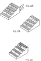
- Figs. 2A-2C are schematic representations of extruder films showing the morphology of the oriented polymer material layers therein.
- the film has a uniaxial orientation, with all molecules oriented in the machine direction, that is, longitudinally with respect to the direction of flow through the die.
- the film has a biaxial orientation. The molecules in the top portions of the film are oriented at an angle of +theta with respect to the machine direction while the portions of the film in the lower part of Fig. 2B are oriented at an angle of -theta to the machine direction.
- Fig. 2C shows a planar isotropic film wherein the polymer rods lie randomly in the film plane, not strongly oriented at any specific angle with respect to the machine direction.
- a biaxially oriented tube can be slit and spread apart to form a flattened film structure.
- the films thus formed will not lie flat.
- the two surface layers of the film inherently have different coefficients of thermal expansion (CTE) axially and transversely to the orientation of its molecules.
- CTE coefficients of thermal expansion
- the transverse CTE is greater. So as the sheet cools, each layer will try to shrink more in its own transverse direction. But since the two layers are both part of the sheet, the sheet as a whole cannot freely shrink in either direction. This stores stresses in the layers and makes the sheet bistable, whereby it is able to hold a curl about either of two different axes and readily adopts one of these two conditions if an active effort is not made to hold it flat.
- liquid crystal polymer films made of poly-(p-phenylene-benzobisthiozole) (PBZT) or the like have this curling problem because they are fibrillar, i.e., they comprise relatively straight molecules.
- the molecules orient strongly in the die and the flowing polymer becomes anisotropic, more so than ordinary coil polymers which tend to randomize.
- a coil polymer tube or sheet can be strengthened biaxially throughout its entire thickness by blowing and drawing after it exits from the die.
- counter-rotating dies are also used to make conventional polymers more isotropic. But the combination of shearing and stretching is much more critical and difficult to optimize with liquid crystal polymer extrudates, since they readily become highly oriented in the die anisotropically. It may not be possible to stretch the polymer substantially in the direction transverse to its fibrillar orientation.
- Nagasawa et al. Japanese Disclosure No. 53-47460, discloses a manufacturing method for a lyotropic liquid crystal polymer film which includes applying transverse shearing forces to the dope. See Fig. 2 and pp. 8-9.
- this disclosure will relate at times to a laminated film structure comprising a number of individual intermediate-product films; and at other times to an integral film structure with different planar regions parallel to its main surfaces which are in some respects analogous to individual films, and having different properties in the various planar regions. It is to be understood that the teachings throughout this disclosure are equally applicable to both these forms of liquid crystal polymer film.
- the use of a term such as "layer” should be understood to refer equally to a planar region within an integral film; as well as to an individual intermediate-product film, or a portion thereof, within a laminated structure.
- a central object of the invention is to form a liquid crystal polymer film with nearly uniform mechanical properties, in particular a film which will lie flat and has a nearly uniform coefficient of thermal expansion in all planar directions, despite any local non-uniformity of the directional coefficients of thermal expansion in its individual layers.
- Another object is to form a liquid crystal polymer film structure comprising two relatively thin outer surface portions which are oriented in a first controllable direction, and a relatively thick inner portion oriented in at least a second controllable direction and possibly partially oriented in a third controllable direction as well.
- a further object is to provide methods which can be carried out by conventional apparatus with little or no modification.
- Yet another object is to provide apparatus for carrying out such methods with greater control and efficiency than is obtainable with conventional apparatus.
- said relatively thick inner portion is controlled to have an orientation which is complementary to that of the two surface portions, the respective directions of these portions preferably defining equal and opposite angles, preferably +/- 45°, with respect to the machine direction in which the extrusion is carried out.
- a method of preparing this type of multiaxially oriented film from liquid crystal polymer comprises the steps of (a) subjecting axially flowing polymer material to transverse-directional motions, thereby straining the axial flow; and (b) solidifying the microscale structural orientation thus obtained.
- a rotational die for extruding this type of ordered liquid crystal polymer film advantageously comprises frame means; inner, middle and outer rotors on said frame means which are concentric and have facing surfaces which define inner and outer annular polymer flow channels; means for providing a flow of polymer to each of said annular channels; and means for rotating the inner and outer rotors in a given direction and rotating the middle rotor in the opposite direction for shearing said polymer flows in said channels.
- the die also includes means for controlling the flow of polymer and the rotation of the rotors for producing a film wherein the fibrillar orientation of the polymer on one side of the midplane of the film is substantially a mirror-image of the orientation on the other side of the midplane.
- Still another object is to provide a method and apparatus for including a central core layer within the relatively thick inner portion, the molecular orientation of the film structure in that central core layer being preferably in or close to the machine direction.
- An additional object is to form a liquid crystal polymer film structure comprising two outer surface layers which are oriented generally in a first controllable direction; two intermediate layers respectively inward of said outer surface layers which are oriented generally in a second controllable direction; and a central core layer sandwiched between said middle layers which is oriented generally in a third controllable direction.
- the central core layer is preferably oriented in or close to the machine direction.
- the intermediate layers may have an orientation which is complementary to that of the adjacent outer layers. The respective directions of orientation of each outer surface layer and the adjacent intermediate layer thus may define equal and opposite angles with respect to the machine direction in which the extrusion is carried out.
- each intermediate layer may be between that of the adjacent outer layer and that of the central core layer, thus providing a gradual change of direction from the outer layers to the central core layer.
- the respective directions of orientation of the outer surface layers and the intermediate layers preferably define equal and opposite angles with respect to the machine direction in which the extrusion is carried out.
- One rotational die for extruding an ordered liquid crystal polymer film comprises: frame means; inner, middle and outer rotors on said frame means which are concentric and have facing surfaces which define inner and outer annular polymer flow channels; means for providing a flow of polymer to each of said annular channels; and means for rotating the inner and outer rotors in a given direction and rotating the middle rotor in the opposite direction for shearing said polymer flows in said channels.
- a slit-type die assembly for extruding a balanced biaxial liquid crystal polymer film comprises a die which has a pair of opposite shorter sides and a pair of opposite longer sides and thereby defines a substantially rectangular cross-section for an axial flow of polymer, said die having slits formed in the shorter sides of said die; and a continuous belt which is movable in a continuous fashion through said slits and thereby substantially parallel to said longer sides; whereby polymer passing axially through said die is subjected to transverse-directional shearing forces by said belt passing in a first direction and transverse shear patterns formed along said longer sides in an opposite second direction.
- Another rotational die for extruding an ordered liquid crystal polymer film comprises: frame means; at least inner, middle and outer mandrels on said frame means which are concentric and have facing surfaces which define inner and outer annular polymer flow channels between said mandrels, and a middle annular flow channel within said middle mandrel; means for providing a flow of polymer to each of said annular channels; and means for rotating at least the inner and outer rotors in selected directions and for shearing said polymer flows in said outer and inner channels.
- a rotational die having more than three rotating or non-rotating mandrels is also considered to be usable to practice the methods and obtain the products described herein.
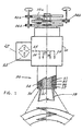
- Fig. 1 is a schematic diagram, partly in cross-section, of a die that is particularly adapted to carry out the process of this invention.
- a flowable ordered-polymer dope is introduced at an inlet 20.
- the dope is passed through a filter/strainer 22 which is of any suitable type and need not be discussed further at this point.
- the dope then passes through a distribution block 24 having a main distribution channel 25 and a group of secondary distribution channels 26-29.
- a die assembly generally designated 30 comprises three tubular rotors, an inner tubular rotor 32, a middle tubular rotor 34, and an outer tubular rotor 36.
- a cylindrical inner space or annulus 33 is defined between the rotors 32 and 34.
- an outer annulus 35 is defined between the rotors 34 and 36.
- the lowermost edge of the rotor 34 has a downward-pointed shape which corresponds to the shapes of the facing inner surfaces of the rotors 32 and 36, so that the thickness dimension of the space 37 is substantially the same as that of the annuli 33 and 35.
- this arrangement is not essential.
- Other examples of advantageous structures can be found by experimentation, and some will be discussed hereinbelow.
- a tubular film 38 is formed and extruded downwardly, and outwardly of a channel 40 through which air is conducted for blowing the film.
- a rotary fitting can be provided, for example, at some point along the channel 40 for introducing the blowing air.
- the inner and outer rotors 32, 36 are rotated in a first direction, for example, clockwise as seen from above in this example.
- the intermediate rotor 34 is rotated in the opposite direction, namely counterclockwise as seen from above in this example.
- the rotors 32, 34, 36 are connected to corresponding coaxial gears 32a, 34a, 36a.
- the gears in turn are rotated by corresponding pinions 32b, 34b, 36b.
- the pinions 32b, 36b may be mounted on a common axis, since they rotate in the same direction so as to rotate the rotors 32 and 36 in the same direction.
- the circumferential shear pattern of the resulting film 38 is illustrated at the bottom of Fig. 1.
- the facing layers of the polymer flows in the annuli 33, 35 are sheared in the second direction by the rotation of the middle rotor 34, so when joined in the space 37, these surfaces combine to form a central portion of the resulting film which thus is oriented strongly toward the second direction.
- the rotation of the inner and outer rotors causes the inner surface of the flow in the annulus 36, and the outer surface of the flow in the annulus 35, to be oriented in the first direction. These two layers form the outer layers of the resulting film.
- the output of this extrusion process is, for example, a biaxially oriented polybenzobisoxazole (PBZO) or polybenzobisthiazole (PBZT) film having outstanding strength and thermal stability.
- PBZO polybenzobisoxazole
- PBZT polybenzobisthiazole
- the PBZO or PBZT films have high strength and stiffness.
- the coefficient of thermal expansion can be made remarkably uniform in all axes of the film.
- the resulting films are especially attractive because of their high thermal and chemical stability and their extremely high tensile mechanical properties.
- Thermotropic polymers that may advantageously be used include the para-oriented aromatic polyesters, such as VectraTM, manufactured by Celanese Corp., and XydarTM, formerly manufactured by Dartco Mfg., Inc., and now manufactured by Amoco, Inc.
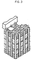
- Fig. 3 shows an example of a printed circuit board comprising ordered-polymer films produced according to the present invention. See U.S. Patent Application Ser. No. 209,281 filed June 20, 1988, incorporated by reference, which relates to printed circuit boards and methods for their production. Materials produced in accordance with the present invention are particularly useful for making such circuit boards.
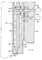
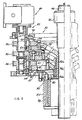
- Fig. 4 is a detailed view showing in cross-section other aspects of the die assembly 30 according to the invention.
- the inner rotor 32 rotates about a blowing air channel 40.
- Polymer material is provided to the inner annulus 33 by a first pump 41.
- Polymer material is provided to the outer annulus 35 by a second pump 42.
- the inner annulus 33 is defined below a seal 43 between the inner rotor 32 and the middle rotor 34.
- a passage is provided from the pump 41 to the annulus 33, through the surrounding support structure illustrated schematically at 50, through a passage 51a.
- a further passage is defined by a pair of seals 45, 47 between the support structure 50 and the outer rotor 36, a passage 51b defined in the outer rotor 36, a pair of seals 44, 46 between the outer rotor 36 and the middle rotor 34, and a passage 51c in the middle rotor 34.
- polymer is provided by the pump 42 to the annulus 35 through, first, a passage 52a in the support structure 50, and a further passage defined by a pair of seals 48, 49 between the support structure 50 and the outer rotor 36, and a passage 52b formed in the outer rotor 36.
- Conventional bleeding means can advantageously be provided from any dead space, for example the annular space between the seals 47 and 48, to the exterior.
- Fig. 5 is a cross-sectional view of the die assembly 30 as well as a bearing assembly generally designated 55.
- the rotors 32, 34, 36 are extended upward, concentric with the air channel 40, by cylindrical extension portions 32a, 34a, 36a.
- the extension portions are further extended by corresponding flange portions 32b, 34b, 36b.
- These flange portions have the shape of conically oriented rings extending outward from the common axis of the rotors and the channel 40, and in this embodiment, at an angle upwardly. As shown, in this example the flange portions are generally parallel to one another.
- the flange portions are further extended by horizontal mounting portions 32c, 34c, 36c. These mounting portions in turn are mounted by screws or the like to respective mounting rings 56, 57, 58.
- respective gear wheels 59, 60, 61 are mounted on the top of radially outward portions of the mounting rings 56, 57, 58. The function of the gear wheels will be discussed further below.
- an enclosure for the bearing assembly is formed by a seamless metal cylinder 62 or the like.
- Ball bearings 63 or the like are mounted between the mounting rings 56, 57, 58 and the cylinder 62.
- a bottom cover 64 generally plate-like, is secured to and supports the bottom of the cylinder 62.
- the bottom cover 64 is supported by the outer, top surface of a generally cylindrical die cover 65 which surrounds the support structure 50 (see Figs. 4 and 5) and thereby surrounds the rotors and associated structure.
- An insulating ring 66 is supported on the die cover 65 and prevents thermal conduction from the die block to the bearing and drive system. As shown by the arrow 67, cooling air can pass freely through respective holes, slots or the like in the flange portions 32b, 34b, the mounting ring 58, and the bottom cover 64, for example by natural or forced convection.
- a top ring 68 Secured to the top of the cylinder 62 is a top ring 68 and supported thereon is a top bearing cover 70.
- the top bearing cover 70 is secured to the top ring 68 by a screw 72 or the like which is operable by a hand knob 74.
- a bushing 76 or the like which is mounted to the top bearing cover 70 defines, at least in part, the air channel 40.
- the mounting portions 32c, 34c, 36c of the rotors 32, 34, 36 are radially staggered. That is, the mounting portion 32c extends radially farther outward than the mounting portion 34c, which in turn extends radially farther outward than the mounting portion 36c.
- the mounting ring 58 extends radially farther inward from the bearings 63 than does the mounting ring 57, which in turn extends radially farther inward than the mounting ring 56.
- the entire combination of the bearing assembly 55 together with the rotors 32, 34, 36 can easily be removed as a unit from the die cover 65, simply by removal of the screws that secure the die cover 65 to the bottom cover 64.
- repair of the die assembly and the like can be easily accomplished without disturbing the polymer supply arrangement including the channels 51a, 52a and corresponding channels associated with the die cover 65 and appropriate fittings.
- the electric heater 78 also shown in Fig. 5, which again is disposed within the die cover 65, for heating the entire die assembly 30.
- the heater 78 is secured in the insulating ring 66 by a bushing or the like 80.
- An electrical conductor 81 is provided for supplying power to the heater 78.
- thermotropic polymers or solvents in the case of lyotropic polymers, are localized in the lower part of the apparatus, which prevents any adverse effect on the bearing assembly and the drive assembly.
- Fig. 6 shows further details of the bearing assembly 55 and the drive assembly 82.
- Slots or the like are formed in the cylinder 62 adjacent to the gear wheels 59, 60, 61.
- Respective pinions 84, 85, 86 are disposed outwardly of and engaging the gear wheels 59, 60, 61 so as to rotate the gear wheels and correspondingly rotate the rotors.
- An assembly 87 which may comprise a motor, a reduction gear, and the like is mounted above and partly supported on the top ring 68 and drives the pinion 84.
- Preferably two additional motors, reduction gears, and the like are provided for independently driving the pinions 85, 86.
- Three separate motors are expected to give the best control over the rotor speed for finely adjusting the shearing forces applied to the polymer.
- the advantageous type of shear pattern similar to that shown in Fig. 1 can be obtained by another method.
- a conventional extrusion die which has two counter-rotating mandrels is known to produce a balanced biaxial film as shown in Fig. 2B.
- Fig. 2B we have discovered that conventional film-layering and film-adhesion apparatus and methods can be used to combine two such layers and thereby obtain a combined film having the shear pattern of Fig. 2B.
- Fig. 7 shows another form of die that can be employed to obtain the film product according to the invention, namely a slit die comprising a moving belt.
- a slit die comprising a moving belt.
- Other types of slit dies are known but the combination of a slit die 90 and an endless belt 91 passing continuously through the die substantially at its middle is a highly advantageous feature of the invention and has not been known to the art.
- a continuous flat stainless steel belt traverses the slit die flow path, setting up a strong transverse shear pattern in a relatively thick middle layer of the flow, as shown in Fig. 8. Recirculation of the polymer material at the lateral sides of the die then sets up a flow pattern whereby relatively thin surface layers at the top and bottom of the die are subjected to a shear opposite to that at the middle of the die.
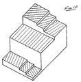
- Fig. 9 illustrates another aspect of the invention.
- Fig. 9 shows a tri-axial (three-annulus) die which is a modification of the embodiments shown in Figs. 1 and 4-6. Only the portions of this embodiment which differ from those in the first embodiment will be discussed, to eliminate redundant explanation.
- the inner rotor 32 and the outer rotor 36 are driven by the corresponding gearing 32a, 32b, 36a, 36b in opposite directions.
- a non-rotating member 34' is disposed between the inner and the outer rotors in a position corresponding to that of the middle rotor 34 in Fig. 1.
- a coaxial annular passage is formed through the non-rotating member 34'. The orientation of the film produced by this die is shown at the bottom of Fig. 9 and also in Fig. 10.
- a substantial central core layer of the film which may constitute about 90% of its thickness, is oriented in the machine direction.
- These surface layers are oriented in complementary directions with respect to the machine direction.
- the orientation advantageously is plus/minus 45°.
- the angle of orientation is reduced gradually between the surface and the central core layer, whereby the direction of orientation gradually becomes the machine direction.
- the flow streams in the three coaxial annular passages do not have to consist of the same polymer of polymer blend.
- an ordered polymer could flow in the annulus 39 while a blended polymer or a coil-like polymer could flow in the outer and inner annuli 33 and 35.
- Co-extrusion is known in the art, but it is not typically practiced with apparatus as shown in Fig. 9.
- the extrudate formed according to Figs. 9 and 10 can be slit to form a film or can be left in tubular form.
- the substantial, nearly uniaxial central core layer gives the resulting film or tube greater tensile and compressive strength (Young's modulus) in the machine direction than products produced with conventional methods and apparatus.
- the strength of the tubing or film is increased depending on the amount of material passing through the non-rotating annulus 39. For example, if less strength but more flexibility is needed, less material could be supplied through the non-rotating annulus 39.
- This embodiment produces an extremely strong tube or film which has some of the advantages of a balanced biaxial film and also enhanced strength due to the uniaxial central core layer.
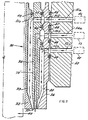
- the embodiment of Figs. 1 and 4-6 can be modified by providing a middle annulus 39' formed within the middle rotor 34. Material is supplied from a pump 3 designated 53 through a passage 54a, 54b, this passage in turn being sealed by an additional seal 92.
- the middle rotor 34 is rotated slowly, to minimize the spiraling orientation of the central core layer which results from the rotation of the middle rotor 34.
- the outer and inner rotors 32, 36 preferably rotate together, at the same rotational speed, but in the opposite direction, creating a shear pattern as shown in Fig. 12.
- the outer and inner rotors preferably rotate at a higher rotational speed than the middle rotor.
- the central core layer 93 is sheared slightly by the motion of the middle rotor and thus is oriented at a small angle which will be defined as a negative angle with respect to the machine direction.
- the respective outer layers 95a, 95b are preferably oriented at a positive angle of at least 45° to the machine direction.
- the angle of orientation of the surface layers should be made as large as possible. A gradual transition between the positive angle of the surface layers 95a, 95b and the core layer 93 occurs in the intermediate layers 94a, 94b.
Landscapes
- Engineering & Computer Science (AREA)
- Mechanical Engineering (AREA)
- Manufacturing & Machinery (AREA)
- Chemical & Material Sciences (AREA)
- Crystallography & Structural Chemistry (AREA)
- Organic Chemistry (AREA)
- Materials Engineering (AREA)
- Microelectronics & Electronic Packaging (AREA)
- Extrusion Moulding Of Plastics Or The Like (AREA)
- Laminated Bodies (AREA)
- Shaping By String And By Release Of Stress In Plastics And The Like (AREA)
- Manufacture Of Macromolecular Shaped Articles (AREA)
- Liquid Crystal Substances (AREA)
- Compositions Of Macromolecular Compounds (AREA)
Claims (30)
- Aus einem geordneten Flüssigkristallpolymer hergestellter Film mit zwei im Wesentlichen parallelen und ebenen Hauptflächen und einer kontrollierten molekularen Ausrichtung in im Wesentlichen jeder Ebene des benannten Films, einer Ausrichtung in jeder Ebene, die durch einen ausgewählten positiven oder negativen Winkel bezüglich einer Achse definiert ist, wobei der benannte Film planare Oberflächenbereiche, in denen die benannten, durch die benannte molekulare Ausrichtung definierten Winkel allgemein als positiv definierte Werte besitzen, sowie einen inneren Bereich besitzt, in dem die benannten Winkel allgemein negative Werte besitzen.
- Film wie in Anspruch 1, worin die benannten Bereiche aus zwei einzelnen, aufeinandergeschichteten Halbfertigfilmen zusammengesetzt sind, deren jeder eine im Wesentlichen biaxiale Ausrichtung besitzt und worin die molekularen Ausrichtungswinkel der einander zugewandten, aufeinandergeschichteten Flächen im Wesentlichen gleich sind.
- Film wie in Anspruch 1, worin die benannten Oberflächenbereiche von im Wesentlichen gleicher Dicke sind, während der benannte innere Bereich dicker als jeder der benannten Oberflächenbereiche ist.
- Aus einem geordneten Flüssigkristallpolymer hergestellter Film mit einer kontrollierten molekularen Ausrichtung in im Wesentlichen jeder beliebigen Ebene des benannten Films, einer Ausrichtung in jeder Ebene, die durch einen ausgewählten positiven oder negativen Winkel bezüglich einer vorbestimmten Achse definiert ist, wobei der benannte Film zwei Oberflächenschichten besitzt, eine der benannten Oberflächenschichten einen durch die benannte molekulare Ausrichtung definierten, positiven Winkel besitzt, die Ausrichtung der anderen Oberflächenschicht negativ ist und der benannte Film eine zentrale Kernschicht besitzt, worin die benannte Ausrichtung allgemein entlang der benannten Achse ist.
- Film wie in einem beliebigen der Ansprüche 1 bis 4, worin der grösste positive und negative Winkel bezüglich der benannten Achse im Wesentlichen gleich ist und worin die benannten grössten Winkel im Wesentlichen ±45° betragen.
- Film wie in Anspruch 1 oder 4, worin die benannten Schichten jeweils Anteile eines integralen Filmaufbaus sind, der durch einen einzigen Düsenspritzprozess gebildet wird und/oder worin die Fibrillenausrichtung auf der einen Seite der Mittelebene der Filme im Wesentlichen ein Spiegelbild der Ausrichtung auf der anderen Seite der Mittelebene ist.
- Film wie in Anspruch 1 oder 4, worin das benannte Polymer aus der Gruppe ausgewählt ist, die aus einem lyotropen Polymer, bevorzugt Poly(p-phenylenbenzobisoxazol), Poly(p-phenylenbenzobisthiazol) und Poly(p-phenylenbenzobisimidazol), und einem thermotropen Polymer, bevorzugt para-ausgerichteten aromatischen Polyestern wie Vectra oder Xydar, besteht.
- Film wie in Anspruch 1 oder 4, worin das benannte Polymer eine Mischung aus einem geordneten Polymer und einem Knäuelpolymer ist oder worin das benannte Polymer eine Mehrzahl verschiedener, ausgewählter geordneter oder Knäuelpolymere bzw. Mischungen, bevorzugt jeweils in betreffenden Schichten in dem benannten Film, beinhaltet.
- Verfahren zur Herstellung eines mehrachsig ausgerichteten Films aus Flüssigkristallpolymer mit den Schritten:bevorzugt den Schritt umfassend, die Filme so zu bilden, dass die Fibrillenausrichtung auf der einen Seite der Filmmittelebene im Wesentlichen ein Spiegelbild der Ausrichtung auf der anderen Seite der Mittelebene ist.(a) axial strömendes Polymermaterial quergerichteten Bewegungen zu unterwerfen und dabei die axiale Strömung zu verspannen; und(b) die in Schritt (a) im Mikromassstab gebildete strukturelle Ausrichtung einzufrieren, und
- Verfahren wie in Anspruch 9, worin der benannte Film gebildet wird, indem zuerst zwei einzelne Halbfertigfilme gebildet werden, deren jeder eine im Wesentlichen biaxiale Ausrichtung hat, und dann die benannten Zwischenfilme in einem kontinuierlichen Prozess aufeinandergeschichtet werden, um den benannten Film zu bilden, wobei der benannte Film innere und Oberflächenbereiche besitzt.
- Verfahren wie in Anspruch 10, worin die benannten Halbfertigfilme biaxiale Filme sind, die unter Verwendung entsprechender gegenläufiger Zweirotordüsen gebildet wurden, deren Rotoren entgegengesetzte Drehrichtungen besitzen, und worin die molekularen Ausrichtungswinkel der einander zugewandten Aufeinanderschichtungsflächen im Wesentlichen gleich sind und/oder worin die benannten Bereiche jeweils Anteile eines integralen Filmaufbaus sind, der durch einen einzigen Düsenspritzprozess gebildet wird.
- Verfahren wie in Anspruch 9, worin der Filmaufbau unter Einsatz einer rohrförmigen Düse (30) gebildet wird, die drei konzentrische Rotoren (32, 34, 36) besitzt, die zwischen sich zwei ringförmige Strömungskanäle (33, 35) bilden; das Polymer durch die bekannten Kanäle (33, 35) zugeführt wird; der äussere (36) und der innere Rotor (32) in einer ersten Richtung gedreht wird, während der mittlere Rotor (34) in der entgegengesetzten Richtung gedreht wird; und die jeweils in den benannten Kanälen (33, 35) gebildeten Polymerströme zusammengefügt werden, um den benannten integralen Filmaufbau zu bilden.
- Verfahren wie in Anspruch 9, worin der benannte Film gebildet wird, indem das benannte Polymer axial durch eine Düse (90) geführt wird, die einen Querschnitt des benannten Polymerstromes definiert; wobei die benannte Düse (90) Schlitze in den gegenüberliegenden Querseiten der benannten Düse (90) besitzt; und ein endloses Band (91) in nur einer Richtung durch die benannten Schlitze und den benannten Polymerstrom geführt wird, das den benannten Querschnitt des benannten Polymerstromes im Wesentlichen halbiert, dadurch die Strömung und entgegengesetzt gerichtete, querverlaufende Schermuster über die Seiten der Düse (90), die keine Schlitze hat, bewirkt, und worin die Düse (90) bevorzugt einen gestreckt rechteckigen Querschnitt des Polymerstromes definiert, die benannten Schlitze sich an den kurzen Seiten des benannten Querschnitts befinden und das benannte endlose Band (91) parallel zu den längeren Seiten des benannten Querschnitts läuft.
- Verfahren wie in Anspruch 9, worin das benannte Polymer lyotrop und das benannte Material eine Gussmasse ist, die das benannte Polymer enthält, das bevorzugt aus der Gruppe ausgewählt ist, die aus Poly(p-phenylenbenzobisoxazol), Poly(pphenylenbenzobisthiozol) und Poly(p-phenylenbenzobismidazol) besteht, oder worin das benannte Polymer thermotrop ist und das benannte Material eine Schmelze des benannten Polymers ist.
- Verfahren, einen mehrachsig ausgerichteten Film aus einem Flüssigkristallpolymer herzustellen, das die Schritte umfasst:(a) eine rohrförmige Düse (30) einzusetzen, die mindestens drei konzentrische Dorne besitzt, darunter einen äusseren (36), einen inneren (32) und einen mittleren (34'), die zwei ringförmige Strömungskanäle (33, 35) zwischen sich sowie einen dritten ringförmigen Strömungskanal (39') innerhalb des benannten mittleren Dorns bilden;(b) eine Menge von Polymer durch die benannten Kanäle zuzuführen;(c) zumindest den äusseren (36) und den inneren (32) Dorn zu drehen; und(d) die in den benannten Kanälen gebildenen, jeweiligen Polymerfilme zusammenzufügen, um den benannten Film zu bilden.
- Verfahren wie in Anspruch 15, worin der benannte äussere (36) und der benannte innere (32) Dorn gedreht werden,entweder in der gleichen Richtung, während der benannte mittlere Dorn (34') langsamer in der umgekehrten Richtung gedreht wird,oder in entgegengesetzten Richtungen, in welchem Falle der benannte mittlere Dorn (34') nicht gedreht wird.
- Verfahren wie in Anspruch 16, worin das benannte Polymer aus der Gruppe ausgewählt ist, die umfasst: ein lyotropes Polymer, in welchem Falle die benannte Menge eine das benannte Polymer enthaltende Gussmasse ist; ein thermotropes Polymer, in welchem Falle die benannte Menge eine Schmelze des benannten Polymers ist; eine Mischung eines geordneten Polymers und eines Knäuelpolymers; und eine Mehrzahl verschiedener, ausgewählter geordneter oder Knäuelpolymere in entsprechenden Schichten innerhalb des benannten Films.
- Flüssigkristallpolymer-Filmspritzdüse zum Spritzen eines geordneten Flüssigkristallpolymerfilms mit:wobei eine Rotationsdüse (30) an den benannten Rahmenmitteln umfasst:Rahmenmitteln;einen inneren (32), einen mittleren (34) und einen äusseren (36) Rotor an den benannten Rahmenmitteln, die konzentrisch sind und einander zugewandte Flächen haben, die einen inneren (33) und einen äusseren (35) ringförmigen Polymerströmungskanal definieren;Mitteln (24), um einen Polymerstrom zu jedem der benannten ringförmigen Kanäle zu liefern; undder innere (32) und der äussere (36) Rotor sich in einer gegebenen Richtung drehen, während der mittlere (34) Rotor sich in der entgegengesetzten Richtung dreht, um die benannten Polymerströme in den benannten Kanälen zu scheren.
- Verwendung einer Rotationsdüse für das Spritzen von Polymeren mitRahmenmitteln;einem inneren (32), einem mittleren (34) und einem äusseren (36) Rotor an den benannten Rahmenmitteln, die konzentrisch sind und einander zugewandte Flächen haben, die einen inneren (33) und einen äusseren (35) ringförmigen Polymerströmungskanal definieren;Mitteln (24), um einen Polymerstrom zu jedem der benannten ringförmigen Kanäle zu liefern; undder innere (32) und der äussere (36) Rotor sich in einer gegebenen Richtung drehen, während der mittlere (34) Rotor sich in der entgegengesetzten Richtung dreht, um die benannten Polymerströme in den benannten Kanälen zu scheren,um einen geordneten Flüssigkristallpolymerfilm zu spritzen, in dem die Fibrillenausrichtung des Polymers auf der einen Seite der Filmmittelebene im Wesentlichen ein Spiegelbild der Ausrichtung auf der anderen Seite der Mittelebene ist.
- Spritzdüse wie in Anspruch 18 zur Herstellung eines Films, in dem die Fibrillenausrichtung des Polymers auf der einen Seite der Filmmittelebene im Wesentlichen ein Spiegelbild der Ausrichtung auf der anderen Seite der Mittelebene ist, weiter Mittel (55, 82) umfassend, um die Strömung des Polymers und die Drehung der Rotoren zu steuern.
- Filmspritzdüse wie in Anspruch 18, weiter umfassend:Rotortragorgane (32a, 32b, 34a, 34b, 36a, 36b), bevorzugt auf einem oberen Umfangsabschnitt der benannten Rahmenmittel, um die Rotoren zu halten und zu drehen; undMittel (56, 57, 58, 70), um die benannten Rotoren (32, 34, 36) von den benannten Rahmenmitteln abnehmen zu können, während die benannten Rotortragorgane auf den benannten Rahmenmitteln an Ort und Stelle verbleiben, wobei weiterdie benannten Rotoren (32, 34, 36) sich bevorzugt an einem zentralen Abschnitt der benannten Rahmenmittel befinden und von den benannten Rotortragorganen aufwärts weggehoben werden können.
- Rotationsdüse zum Spritzen eines geordneten Flüssigkristallpolymerfilms mit:Rahmenmitteln;mindestens einem inneren (32), einem mittleren (34') und einem äusseren (36) Dorn oder Rotor auf den benannten Rahmenmitteln, die konzentrisch sind und einander zugewandte Flächen besitzen, die einen inneren (33) und einen äusseren (35) Polymerströmungskanal zwischen den benannten Dornen oder Rotoren definieren, sowie einem mittleren (39) ringförmigen Strömungskanal in dem benannten mittleren Dorn oder Rotor;Mitteln (3, 53, 54a, 54b), um einen Polymerstrom zu jedem der benannten ringförmigen Kanäle zu liefern; undMitteln (32a, 32b, 36a, 36b), um zumindest den inneren (32) und den äusseren (36) Dorn oder Rotor in ausgewählten Richtungen zu drehen, um die benannten Polymerströme in dem benannten äusseren (35) und dem benannten inneren (33) Kanal zu scheren.
- Düse wie in Anspruch 18, weiter Mittel umfassend, um wahlweise den mittleren Dorn (34') oder Rotor ortsfest zu halten oder in einer gewählten Richtung zu drehen; und bevorzugt weiter Mittel umfassend, um den Polymerstrom und die Drehung der Dorne oder Rotoren (32, 34', 36) zu steuern und so einen Film zu erzeugen, in dem die Fibrillenausrichtung des Polymers auf der einen Seite der Filmmittelebene im Wesentlichen ein Spiegelbild der Ausrichtung auf der anderen Seite der Mittelebene ist.
- Düse wie in Anspruch 18 oder 23, weiter Dorn- bzw. Rotortragorgane auf den benannten Rahmenmitteln (32a, 32b, 32c, 34a, 34b, 34c, 36a, 36b, 36c) umfassend, um die Dorne bzw. Rotoren zu halten und zu drehen, wobei die benannten Dorn- bzw. Rotortragorgane von den Mitteln zur Lieferung eines steuerbaren Polymerstromes beabstandet sind; und wobeidie benannten Dorn- bzw. Rotortragorgane auf einem oberen Abschnitt an den Rahmenmitteln sind, während die benannten Polymerliefermittel auf einem unteren Abschnitt (64) der Rahmenmittel sind und/oder die benannte Beabstandung die Dorn- bzw. Rotortragorgane vor der Wärme und den Fluiden schützt, die an den benannten Polymerliefermitteln (24) vorhanden sein können.
- Düse wie in einem beliebigen der Ansprüche 18, 22, 23 oder 24, weiter Kühlorgane (40) umfassend, insbesondere um die benannten Rotoren, Rotortragorgane, Dorne oder Dorntragorgane zu kühlen.
- Düse wie in einem beliebigen der Ansprüche 23 bis 25, weiter umfassend:Dorntragorgane, bevorzugt auf einem oberen Umfangsabschnitt der benannten Rahmenmittel, um die Dorne zu halten und zu drehen; sowie Mittel, um die benannten Dorne von den benannten Rahmenmitteln entfernen zu können, während die benannten Dorntragorgane auf den benannten Rahmenmitteln an Ort und Stelle verbleiben, wobei die benannten Dorne bevorzugt an einem zentralen Abschnitt der benannten Rahmenmittel sind und von den benannten Dorntragorganen nach oben weggehoben werden können.
- Schlitzdüsengruppe zum Spritzen eines ausgewogenen biaxialen Flüssigkristallpolymerfilms, wobei die benannte Gruppe umfasst: eine Düse (90), die ein Paar einander gegenüberliegender kürzerer Seiten und ein Paar einander gegenüberliegender längerer Seiten besitzt und dadurch einen im Wesentlichen rechteckigen Querschnitt für eine Axialströmung des Polymers definiert, wobei an der benannten Düse die Schlitze in den kürzeren Seiten der benannten Düse ausgebildet sind; sowie ein endloses Band (91), das kontinuierlich durch die benannten Schlitze und somit im Wesentlichen parallel zu den benannten längeren Seiten bewegt werden kann; wobei axial durch die benannte Düse hindurchgehendes Polymer quer gerichteten Scherkräften unterworfen wird, indem das benannte Band in einer ersten Richtung läuft und querverlaufende Schermuster entlang der benannten längeren Seiten in einer entgegengesetzten, zweiten Richtung ausgebildet werden.
- Gruppe wie in Anspruch 27, worin die benannten Schlitze und somit das benannte Band (91) sich im Wesentlichen in der Mitte zwischen den benannten längeren Seiten der benannten Düse befinden, wobei das benannte Band bevorzugt aus rostfreiem Stahl gefertigt ist.
- Schaltungsplatte mit zumindest einem ausgewogenen biaxialen Flüssigkristallpolymerfilm nach einem beliebigen der Ansprüche 1 bis 3 oder 7 sowie Mitteln auf dem benannten Film, um leitend an ein elektronisches Schaltkreiselement angeschlossen zu werden.
- Schaltungsplatte wie in Anspruch 29, worin der benannte Film aus einer Mischung eines geordneten Polymers und eines Knäuelpolymers gefertigt ist.
Applications Claiming Priority (3)
| Application Number | Priority Date | Filing Date | Title |
|---|---|---|---|
| US36743389A | 1989-06-16 | 1989-06-16 | |
| US367433 | 1989-06-16 | ||
| PCT/US1990/003394 WO1990015706A1 (en) | 1989-06-16 | 1990-06-18 | Liquid crystal polymer film |
Publications (3)
| Publication Number | Publication Date |
|---|---|
| EP0477291A1 EP0477291A1 (de) | 1992-04-01 |
| EP0477291A4 EP0477291A4 (en) | 1992-11-19 |
| EP0477291B1 true EP0477291B1 (de) | 2002-10-16 |
Family
ID=23447146
Family Applications (1)
| Application Number | Title | Priority Date | Filing Date |
|---|---|---|---|
| EP90910243A Expired - Lifetime EP0477291B1 (de) | 1989-06-16 | 1990-06-18 | Polymerfilm aus flüssigkristall |
Country Status (7)
| Country | Link |
|---|---|
| US (1) | US5288529A (de) |
| EP (1) | EP0477291B1 (de) |
| JP (5) | JP3210008B2 (de) |
| AT (1) | ATE226136T1 (de) |
| CA (1) | CA2064808C (de) |
| DE (1) | DE69034011T2 (de) |
| WO (1) | WO1990015706A1 (de) |
Families Citing this family (47)
| Publication number | Priority date | Publication date | Assignee | Title |
|---|---|---|---|---|
| ATE91638T1 (de) * | 1989-09-25 | 1993-08-15 | Schneider Usa Inc | Mehrschichtextrusion als verfahren zur herstellung von ballons zur gefaessplastik. |
| US5843539A (en) * | 1991-12-12 | 1998-12-01 | Foster-Miller, Inc. | Coextrusion of liquid crystal polymers and thermoplastic polymers to form a container |
| EP0617111B1 (de) * | 1993-03-25 | 1997-09-17 | Sumitomo Chemical Company Limited | Optisch anisotropisches Material, Verfahren zur Herstellung, Verzögerungsplatte und flüssigkristalline Anzeige, die es verwendet |
| US6179818B1 (en) * | 1994-11-14 | 2001-01-30 | Bristol-Myers Squibb Company | Ostomy bags and vessels for biological materials |
| TW370548B (en) * | 1995-04-12 | 1999-09-21 | Sumitomo Chemical Co | Liquid crystal polyester resin composition film |
| US5843501A (en) * | 1996-01-25 | 1998-12-01 | Foster Miller, Inc. | Retortable extended shelf life food container |
| US5882741A (en) * | 1996-01-26 | 1999-03-16 | Foster-Miller, Inc. | Members having a multiaxially oriented coating of thermotropic liquid crystalline polymer and method and apparatus for producing such members |
| AU2246197A (en) * | 1996-01-26 | 1997-08-20 | Foster-Miller Inc. | Die with grooved feed zone for extruding polymer |
| US6064007A (en) * | 1996-04-29 | 2000-05-16 | Electric Power Research Institute Inc. | Moisture resistant underground cable |
| JP3373528B2 (ja) | 1996-09-11 | 2003-02-04 | デュポン カナダ インコーポレイテッド | 液晶ポリマー層を含有する熱交換器 |
| EP0925182A1 (de) | 1996-09-11 | 1999-06-30 | Dupont Canada Inc. | Mehrschichtige wärmetauscher aus polymer, die eine sperrschicht enthalten |
| US6267915B1 (en) | 1996-09-12 | 2001-07-31 | University Of Florida | Production method for objects with radially-varying properties |
| US5904884A (en) * | 1997-06-26 | 1999-05-18 | Decoma International Inc. | Method of forming automotive trim strip from extruded thermoplastic materials |
| US6007902A (en) * | 1997-08-19 | 1999-12-28 | International Paper Company | Multi-layer structure with heat stable high barrier polymer, method therefor and product therefrom |
| US6248469B1 (en) | 1997-08-29 | 2001-06-19 | Foster-Miller, Inc. | Composite solid polymer electrolyte membranes |
| US6268026B1 (en) | 1997-10-20 | 2001-07-31 | Hoechst Celanese Corporation | Multilayer laminate formed from a substantially stretched non-molten wholly aromatic liquid crystalline polymer and non-liquid crystalline polyester and method for forming same |
| US6312772B1 (en) | 1997-10-20 | 2001-11-06 | Hoechst Celanese Corporation | Multilayer laminate formed from a substantially stretched non-molten wholly aromatic liquid crystalline polymer and non-polyester thermoplastic polymer |
| US6103151A (en) * | 1998-03-05 | 2000-08-15 | Standard Starch, Llc | Extrusion die for biodegradable material with flow control device |
| US6183672B1 (en) | 1998-03-05 | 2001-02-06 | Standard Starch, Llc | Extrusion die for biodegradable material with die orifice modifying device and flow control device |
| CA2323157C (en) * | 1998-03-05 | 2008-09-30 | Standard Starch, L.L.C. | Extrusion die for biodegradable material with die orifice modifying device and flow control device |
| US7550216B2 (en) * | 1999-03-03 | 2009-06-23 | Foster-Miller, Inc. | Composite solid polymer electrolyte membranes |
| US6528164B1 (en) | 1999-09-03 | 2003-03-04 | Sumitomo Chemical Company, Limited | Process for producing aromatic liquid crystalline polyester and film thereof |
| WO2002049405A2 (en) | 2000-08-15 | 2002-06-20 | World Properties, Inc. | Multi-layer circuits and methods of manufacture thereof |
| US20020064701A1 (en) * | 2000-09-11 | 2002-05-30 | Hand Doris I. | Conductive liquid crystalline polymer film and method of manufacture thereof |
| AU2001292823A1 (en) | 2000-09-20 | 2002-04-02 | World Properties Inc. | Electrostatic deposition of high temperature, high performance thermoplastics |
| US6602583B2 (en) * | 2000-12-14 | 2003-08-05 | World Properties, Inc. | Liquid crystalline polymer bond plies and circuits formed therefrom |
| US6599451B2 (en) | 2001-02-13 | 2003-07-29 | Hans G. Franke | Rotating extrusion die with spray nozzle |
| US20050208278A1 (en) * | 2001-08-22 | 2005-09-22 | Landi Vincent R | Method for improving bonding of circuit substrates to metal and articles formed thereby |
| WO2004026009A1 (en) | 2002-09-16 | 2004-03-25 | World Properties, Inc. | Liquid crystalline polymer composites, method of manufacture thereof, and articles formed therefrom |
| US7227179B2 (en) * | 2002-09-30 | 2007-06-05 | World Properties, Inc. | Circuit materials, circuits, multi-layer circuits, and methods of manufacture thereof |
| US7180172B2 (en) * | 2003-06-19 | 2007-02-20 | World Properties, Inc. | Circuits, multi-layer circuits, and methods of manufacture thereof |
| WO2005040307A1 (en) * | 2003-10-18 | 2005-05-06 | Merck Patent Gmbh | Barrier coating composition containing a liquid crystalline polymer as well as a device containing this barrier coating composition |
| US7549220B2 (en) * | 2003-12-17 | 2009-06-23 | World Properties, Inc. | Method for making a multilayer circuit |
| CN1914961A (zh) * | 2004-01-20 | 2007-02-14 | 环球产权公司 | 电路材料、电路、多层电路及其制造方法 |
| US7524388B2 (en) * | 2005-05-10 | 2009-04-28 | World Properties, Inc. | Composites, method of manufacture thereof, and articles formed therefrom |
| US7513766B2 (en) * | 2005-10-11 | 2009-04-07 | Cryovac, Inc. | Extrusion apparatus having a driven feed segment |
| US20070107932A1 (en) * | 2005-11-09 | 2007-05-17 | Jauniskis Linas A | Moisture resistant chip package |
| JP2009012428A (ja) * | 2007-07-09 | 2009-01-22 | Bridgestone Corp | 多層樹脂ベルトの製造方法およびそれにより得られる多層樹脂ベルト |
| DE102010061794A1 (de) * | 2010-05-04 | 2011-11-10 | Andreas Sausner | Verfahren und Vorrichtung zum Umformen von Metallen und Kunststoffen |
| RS58035B1 (sr) * | 2011-07-12 | 2019-02-28 | Fabios Spolka Akcyjna | Uređaj za ekstruziju i postupak za proizvodnju cilindričnog kolagenskog omota |
| US8853344B2 (en) | 2012-11-09 | 2014-10-07 | Ticona Llc | Liquid crystalline polymer composition for films |
| CN103009602B (zh) * | 2012-12-19 | 2014-08-20 | 广东金明精机股份有限公司 | 同心套筒式五层共挤吹膜机头 |
| TWI636127B (zh) | 2015-06-25 | 2018-09-21 | 財團法人工業技術研究院 | 液晶高分子複合膜 |
| CN105171948B (zh) * | 2015-08-19 | 2017-09-12 | 上海华特汽车配件有限公司 | Ema热膨胀材料的自动化配料造粒方法 |
| EP3749500A4 (de) * | 2018-02-06 | 2021-05-19 | James Prue | System, vorrichtung und verfahren zur herstellung eines geflechtverstärkten rohrs |
| CN112549475B (zh) * | 2020-11-24 | 2022-04-19 | 中国科学技术大学 | 一种制备液晶高分子薄膜的方法及制备装置 |
| CN114025517B (zh) * | 2021-09-24 | 2024-04-12 | 上海航天电子通讯设备研究所 | 一种lcp多层电路板平坦化层压方法及装置 |
Family Cites Families (22)
| Publication number | Priority date | Publication date | Assignee | Title |
|---|---|---|---|---|
| DE659706C (de) * | 1934-03-30 | 1938-05-10 | Becker & Co Naturinwerk | Wursthuelle aus faserigen Pressmassen, insbesondere aus zerkleinerten Hautabfaellen |
| US3790326A (en) * | 1971-11-26 | 1974-02-05 | Conwed Corp | Extrusion apparatus |
| JPS595407B2 (ja) * | 1976-10-12 | 1984-02-04 | 旭化成株式会社 | 芳香族ポリアミドフイルムの製造法 |
| JPS57131527A (en) * | 1981-02-09 | 1982-08-14 | Ekuseru Kk | Manufacturing device of fiber-reinforced pressure hose |
| US4377546A (en) * | 1981-08-11 | 1983-03-22 | The United States Of America As Represented By The Secretary Of The Air Force | Process for producing aromatic heterocyclic polymer alloys |
| JPS58191137A (ja) * | 1982-04-30 | 1983-11-08 | Toyoda Gosei Co Ltd | 薄膜ゴムシ−ト用押出成形機 |
| JPS6178863A (ja) * | 1984-09-27 | 1986-04-22 | Toray Ind Inc | 二軸配向ポリエステルフイルム |
| US4939235A (en) * | 1985-09-26 | 1990-07-03 | Foster-Miller, Inc. | Biaxially oriented ordered polybenzothiazole film |
| JPS6295213A (ja) * | 1985-10-23 | 1987-05-01 | Asahi Chem Ind Co Ltd | 積層フイルム及びその製造法 |
| JPS632768A (ja) * | 1986-06-23 | 1988-01-07 | Iseki & Co Ltd | 乗用型走行車体 |
| JPS6374622A (ja) * | 1986-09-19 | 1988-04-05 | Asahi Chem Ind Co Ltd | フイルムの製造法 |
| US4871595A (en) * | 1986-12-16 | 1989-10-03 | Foster Miller, Inc. | Lyotropic liquid crystalline oriented polymer substrate for printed wire board |
| US4851503A (en) * | 1986-12-29 | 1989-07-25 | Kuraray Company, Ltd. | Wholly aromatic thermotropic liquid crystal polyester |
| JPH0829560B2 (ja) * | 1987-02-13 | 1996-03-27 | 三菱化学株式会社 | 多層フイルムの成形方法 |
| JPS63264323A (ja) * | 1987-04-23 | 1988-11-01 | Sumitomo Bakelite Co Ltd | 液晶性全芳香族ポリエステルフイルムの製造方法 |
| JPS63296920A (ja) * | 1987-05-29 | 1988-12-05 | Sumitomo Bakelite Co Ltd | 液晶性全芳香族ポリエステルフィルムの製造方法 |
| DE3737889A1 (de) * | 1987-11-07 | 1989-05-18 | Basf Ag | Leiterplattensubstrate mit verbesserter waermeleitfaehigkeit |
| US4975312A (en) * | 1988-06-20 | 1990-12-04 | Foster-Miller, Inc. | Multiaxially oriented thermotropic polymer substrate for printed wire board |
| JPH0289616A (ja) * | 1988-09-28 | 1990-03-29 | Daicel Chem Ind Ltd | フィルムとその製造方法 |
| JPH0822568B2 (ja) * | 1988-09-28 | 1996-03-06 | ダイセル化学工業株式会社 | フィルムとその製造方法 |
| JPH0298423A (ja) * | 1988-10-05 | 1990-04-10 | Toray Ind Inc | 液晶ポリマフィルム |
| JPH032768A (ja) * | 1989-05-30 | 1991-01-09 | Tokyo Electric Co Ltd | レーザビームプリンタ |
-
1990
- 1990-06-18 JP JP50955890A patent/JP3210008B2/ja not_active Expired - Lifetime
- 1990-06-18 EP EP90910243A patent/EP0477291B1/de not_active Expired - Lifetime
- 1990-06-18 US US07/778,812 patent/US5288529A/en not_active Expired - Lifetime
- 1990-06-18 AT AT90910243T patent/ATE226136T1/de not_active IP Right Cessation
- 1990-06-18 WO PCT/US1990/003394 patent/WO1990015706A1/en active IP Right Grant
- 1990-06-18 CA CA002064808A patent/CA2064808C/en not_active Expired - Lifetime
- 1990-06-18 DE DE69034011T patent/DE69034011T2/de not_active Expired - Lifetime
-
2001
- 2001-04-27 JP JP2001131601A patent/JP3483863B2/ja not_active Expired - Lifetime
- 2001-04-27 JP JP2001131586A patent/JP2001310367A/ja not_active Withdrawn
-
2004
- 2004-06-25 JP JP2004188493A patent/JP2004322653A/ja not_active Withdrawn
-
2005
- 2005-10-20 JP JP2005305778A patent/JP4261540B2/ja not_active Expired - Lifetime
Also Published As
| Publication number | Publication date |
|---|---|
| US5288529A (en) | 1994-02-22 |
| ATE226136T1 (de) | 2002-11-15 |
| DE69034011T2 (de) | 2003-08-14 |
| JP2001315190A (ja) | 2001-11-13 |
| JPH04506779A (ja) | 1992-11-26 |
| WO1990015706A1 (en) | 1990-12-27 |
| JP2006069221A (ja) | 2006-03-16 |
| CA2064808A1 (en) | 1990-12-17 |
| JP3483863B2 (ja) | 2004-01-06 |
| JP2004322653A (ja) | 2004-11-18 |
| EP0477291A1 (de) | 1992-04-01 |
| EP0477291A4 (en) | 1992-11-19 |
| JP2001310367A (ja) | 2001-11-06 |
| JP3210008B2 (ja) | 2001-09-17 |
| DE69034011D1 (de) | 2002-11-21 |
| CA2064808C (en) | 2000-08-15 |
| JP4261540B2 (ja) | 2009-04-30 |
Similar Documents
| Publication | Publication Date | Title |
|---|---|---|
| EP0477291B1 (de) | Polymerfilm aus flüssigkristall | |
| JP2613659B2 (ja) | 多軸配向熱変性ポリマーフィルム及びその製造方法 | |
| US5589236A (en) | Coextrusion of liquid crystal polymers and thermoplastic polymers | |
| US4963428A (en) | Biaxially oriented ordered polymer films | |
| US4939235A (en) | Biaxially oriented ordered polybenzothiazole film | |
| US3909170A (en) | Adjustable flat spinneret for the coextrusion of flat films comprising a plurality of components | |
| US5843539A (en) | Coextrusion of liquid crystal polymers and thermoplastic polymers to form a container | |
| JPH07251438A (ja) | 液晶ポリマーフィルム及びその製造方法 | |
| US6027771A (en) | Liquid crystal polymer film and a method for manufacturing the same | |
| CN110181829B (zh) | 一种液晶聚酯薄膜工业生产工艺 | |
| MXPA97006660A (en) | Coextrusion of liquid crystal polymers and thermoplastic polymers to form a contene | |
| US5282731A (en) | Apparatus for the production of moldings from thermotropic, liquid-crystalline substances | |
| US6045737A (en) | Coextrusion of liquid crystal polymers and thermoplastic polymers | |
| US6132668A (en) | Biaxially oriented ordered polymer films | |
| WO2007096472A1 (en) | Method and apparatus for producing plastic film | |
| WO1991002042A1 (en) | Thermoplastic web and process for manufacturing same | |
| JP2962459B2 (ja) | 液晶ポリマーフィルム及びその製造方法 | |
| JP4060983B2 (ja) | インフレーション製膜装置および製膜方法並びに熱可塑性液晶ポリマーフィルム | |
| WO2015107095A1 (en) | Polymer film | |
| JP2613659C (de) | ||
| JPH01130930A (ja) | 液晶性全芳香族ポリエステルフィルムの製造方法 | |
| JPS63264323A (ja) | 液晶性全芳香族ポリエステルフイルムの製造方法 | |
| CA1327688C (en) | Biaxially oriented ordered polymer films | |
| JP2001030352A (ja) | 二軸延伸フィルムの製造方法 | |
| JP2001341199A (ja) | 逐次二軸延伸フィルムの製造方法 |
Legal Events
| Date | Code | Title | Description |
|---|---|---|---|
| PUAI | Public reference made under article 153(3) epc to a published international application that has entered the european phase |
Free format text: ORIGINAL CODE: 0009012 |
|
| 17P | Request for examination filed |
Effective date: 19911216 |
|
| AK | Designated contracting states |
Kind code of ref document: A1 Designated state(s): AT BE CH DE DK ES FR GB IT LI LU NL SE |
|
| A4 | Supplementary search report drawn up and despatched |
Effective date: 19920928 |
|
| AK | Designated contracting states |
Kind code of ref document: A4 Designated state(s): AT BE CH DE DK ES FR GB IT LI LU NL SE |
|
| 17Q | First examination report despatched |
Effective date: 19961030 |
|
| GRAG | Despatch of communication of intention to grant |
Free format text: ORIGINAL CODE: EPIDOS AGRA |
|
| GRAG | Despatch of communication of intention to grant |
Free format text: ORIGINAL CODE: EPIDOS AGRA |
|
| GRAH | Despatch of communication of intention to grant a patent |
Free format text: ORIGINAL CODE: EPIDOS IGRA |
|
| RAP1 | Party data changed (applicant data changed or rights of an application transferred) |
Owner name: FOSTER-MILLER, INC. |
|
| GRAH | Despatch of communication of intention to grant a patent |
Free format text: ORIGINAL CODE: EPIDOS IGRA |
|
| GRAA | (expected) grant |
Free format text: ORIGINAL CODE: 0009210 |
|
| AK | Designated contracting states |
Kind code of ref document: B1 Designated state(s): AT BE CH DE DK ES FR GB IT LI LU NL SE |
|
| PG25 | Lapsed in a contracting state [announced via postgrant information from national office to epo] |
Ref country code: NL Free format text: LAPSE BECAUSE OF FAILURE TO SUBMIT A TRANSLATION OF THE DESCRIPTION OR TO PAY THE FEE WITHIN THE PRESCRIBED TIME-LIMIT Effective date: 20021016 Ref country code: AT Free format text: LAPSE BECAUSE OF FAILURE TO SUBMIT A TRANSLATION OF THE DESCRIPTION OR TO PAY THE FEE WITHIN THE PRESCRIBED TIME-LIMIT Effective date: 20021016 Ref country code: CH Free format text: LAPSE BECAUSE OF FAILURE TO SUBMIT A TRANSLATION OF THE DESCRIPTION OR TO PAY THE FEE WITHIN THE PRESCRIBED TIME-LIMIT Effective date: 20021016 Ref country code: LI Free format text: LAPSE BECAUSE OF FAILURE TO SUBMIT A TRANSLATION OF THE DESCRIPTION OR TO PAY THE FEE WITHIN THE PRESCRIBED TIME-LIMIT Effective date: 20021016 |
|
| REF | Corresponds to: |
Ref document number: 226136 Country of ref document: AT Date of ref document: 20021115 Kind code of ref document: T |
|
| REG | Reference to a national code |
Ref country code: GB Ref legal event code: FG4D |
|
| REG | Reference to a national code |
Ref country code: CH Ref legal event code: EP |
|
| REF | Corresponds to: |
Ref document number: 69034011 Country of ref document: DE Date of ref document: 20021121 |
|
| PG25 | Lapsed in a contracting state [announced via postgrant information from national office to epo] |
Ref country code: DK Free format text: LAPSE BECAUSE OF FAILURE TO SUBMIT A TRANSLATION OF THE DESCRIPTION OR TO PAY THE FEE WITHIN THE PRESCRIBED TIME-LIMIT Effective date: 20030116 Ref country code: SE Free format text: LAPSE BECAUSE OF FAILURE TO SUBMIT A TRANSLATION OF THE DESCRIPTION OR TO PAY THE FEE WITHIN THE PRESCRIBED TIME-LIMIT Effective date: 20030116 |
|
| ET | Fr: translation filed | ||
| NLV1 | Nl: lapsed or annulled due to failure to fulfill the requirements of art. 29p and 29m of the patents act | ||
| PG25 | Lapsed in a contracting state [announced via postgrant information from national office to epo] |
Ref country code: ES Free format text: LAPSE BECAUSE OF FAILURE TO SUBMIT A TRANSLATION OF THE DESCRIPTION OR TO PAY THE FEE WITHIN THE PRESCRIBED TIME-LIMIT Effective date: 20030429 |
|
| REG | Reference to a national code |
Ref country code: CH Ref legal event code: PL |
|
| PG25 | Lapsed in a contracting state [announced via postgrant information from national office to epo] |
Ref country code: LU Free format text: LAPSE BECAUSE OF NON-PAYMENT OF DUE FEES Effective date: 20030618 |
|
| PLBE | No opposition filed within time limit |
Free format text: ORIGINAL CODE: 0009261 |
|
| STAA | Information on the status of an ep patent application or granted ep patent |
Free format text: STATUS: NO OPPOSITION FILED WITHIN TIME LIMIT |
|
| 26N | No opposition filed |
Effective date: 20030717 |
|
| PGFP | Annual fee paid to national office [announced via postgrant information from national office to epo] |
Ref country code: FR Payment date: 20090527 Year of fee payment: 20 Ref country code: IT Payment date: 20090616 Year of fee payment: 20 |
|
| PGFP | Annual fee paid to national office [announced via postgrant information from national office to epo] |
Ref country code: BE Payment date: 20090505 Year of fee payment: 20 |
|
| PGFP | Annual fee paid to national office [announced via postgrant information from national office to epo] |
Ref country code: GB Payment date: 20090617 Year of fee payment: 20 Ref country code: DE Payment date: 20090505 Year of fee payment: 20 |
|
| BE20 | Be: patent expired |
Owner name: *FOSTER-MILLER INC. Effective date: 20100618 |
|
| REG | Reference to a national code |
Ref country code: GB Ref legal event code: PE20 Expiry date: 20100617 |
|
| PG25 | Lapsed in a contracting state [announced via postgrant information from national office to epo] |
Ref country code: GB Free format text: LAPSE BECAUSE OF EXPIRATION OF PROTECTION Effective date: 20100617 |
|
| PG25 | Lapsed in a contracting state [announced via postgrant information from national office to epo] |
Ref country code: DE Free format text: LAPSE BECAUSE OF EXPIRATION OF PROTECTION Effective date: 20100618 |