US7550216B2 - Composite solid polymer electrolyte membranes - Google Patents
Composite solid polymer electrolyte membranes Download PDFInfo
- Publication number
- US7550216B2 US7550216B2 US10/851,478 US85147804A US7550216B2 US 7550216 B2 US7550216 B2 US 7550216B2 US 85147804 A US85147804 A US 85147804A US 7550216 B2 US7550216 B2 US 7550216B2
- Authority
- US
- United States
- Prior art keywords
- spem
- polymer
- ion
- sulfonated
- conducting
- Prior art date
- Legal status (The legal status is an assumption and is not a legal conclusion. Google has not performed a legal analysis and makes no representation as to the accuracy of the status listed.)
- Expired - Fee Related, expires
Links
- 239000012528 membrane Substances 0.000 title claims abstract description 185
- 239000002131 composite material Substances 0.000 title claims abstract description 74
- 239000007787 solid Substances 0.000 title claims abstract description 34
- 239000005518 polymer electrolyte Substances 0.000 title claims abstract description 31
- XLYOFNOQVPJJNP-UHFFFAOYSA-N water Substances O XLYOFNOQVPJJNP-UHFFFAOYSA-N 0.000 claims abstract description 190
- 229910001868 water Inorganic materials 0.000 claims abstract description 159
- 229920000307 polymer substrate Polymers 0.000 claims abstract description 77
- 239000004020 conductor Substances 0.000 claims abstract description 73
- 229920000642 polymer Polymers 0.000 claims description 240
- 229920001940 conductive polymer Polymers 0.000 claims description 112
- 239000002322 conducting polymer Substances 0.000 claims description 74
- 239000000758 substrate Substances 0.000 claims description 69
- 229920002577 polybenzoxazole Polymers 0.000 claims description 57
- -1 poly(trifluorostyrene) Polymers 0.000 claims description 48
- 229920002492 poly(sulfone) Polymers 0.000 claims description 31
- 239000011148 porous material Substances 0.000 claims description 30
- 239000000203 mixture Substances 0.000 claims description 27
- 239000004642 Polyimide Substances 0.000 claims description 26
- 229920001721 polyimide Polymers 0.000 claims description 26
- 125000003118 aryl group Chemical group 0.000 claims description 25
- 239000000178 monomer Substances 0.000 claims description 21
- 150000003457 sulfones Chemical class 0.000 claims description 19
- 229910052760 oxygen Inorganic materials 0.000 claims description 15
- LSNNMFCWUKXFEE-UHFFFAOYSA-M Bisulfite Chemical compound OS([O-])=O LSNNMFCWUKXFEE-UHFFFAOYSA-M 0.000 claims description 12
- 229920000106 Liquid crystal polymer Polymers 0.000 claims description 11
- 229920001577 copolymer Polymers 0.000 claims description 11
- 238000005342 ion exchange Methods 0.000 claims description 11
- 125000000542 sulfonic acid group Chemical group 0.000 claims description 11
- 229920001519 homopolymer Polymers 0.000 claims description 10
- 229920000172 poly(styrenesulfonic acid) Polymers 0.000 claims description 10
- 229920002554 vinyl polymer Polymers 0.000 claims description 10
- 229920012266 Poly(ether sulfone) PES Polymers 0.000 claims description 7
- 238000009833 condensation Methods 0.000 claims description 6
- 230000005494 condensation Effects 0.000 claims description 6
- 229910052717 sulfur Inorganic materials 0.000 claims description 6
- 229940005642 polystyrene sulfonic acid Drugs 0.000 claims description 5
- IOJUPLGTWVMSFF-UHFFFAOYSA-N benzothiazole Chemical compound C1=CC=C2SC=NC2=C1 IOJUPLGTWVMSFF-UHFFFAOYSA-N 0.000 claims description 4
- 230000002535 lyotropic effect Effects 0.000 claims description 4
- 239000003963 antioxidant agent Substances 0.000 claims description 3
- 150000001875 compounds Chemical class 0.000 claims description 3
- BCMCBBGGLRIHSE-UHFFFAOYSA-N 1,3-benzoxazole Chemical compound C1=CC=C2OC=NC2=C1 BCMCBBGGLRIHSE-UHFFFAOYSA-N 0.000 claims description 2
- HYZJCKYKOHLVJF-UHFFFAOYSA-N 1H-benzimidazole Chemical compound C1=CC=C2NC=NC2=C1 HYZJCKYKOHLVJF-UHFFFAOYSA-N 0.000 claims description 2
- OKTJSMMVPCPJKN-UHFFFAOYSA-N Carbon Chemical group [C] OKTJSMMVPCPJKN-UHFFFAOYSA-N 0.000 claims description 2
- WYLQRHZSKIDFEP-UHFFFAOYSA-N benzene-1,4-dithiol Chemical compound SC1=CC=C(S)C=C1 WYLQRHZSKIDFEP-UHFFFAOYSA-N 0.000 claims description 2
- 125000001624 naphthyl group Chemical group 0.000 claims description 2
- 125000001997 phenyl group Chemical group [H]C1=C([H])C([H])=C(*)C([H])=C1[H] 0.000 claims description 2
- JUJWROOIHBZHMG-UHFFFAOYSA-N pyridine Substances C1=CC=NC=C1 JUJWROOIHBZHMG-UHFFFAOYSA-N 0.000 claims description 2
- 239000000446 fuel Substances 0.000 abstract description 68
- 238000000909 electrodialysis Methods 0.000 abstract description 2
- 239000000243 solution Substances 0.000 description 132
- OKKJLVBELUTLKV-UHFFFAOYSA-N Methanol Chemical compound OC OKKJLVBELUTLKV-UHFFFAOYSA-N 0.000 description 114
- 238000000034 method Methods 0.000 description 96
- YMWUJEATGCHHMB-UHFFFAOYSA-N Dichloromethane Chemical compound ClCCl YMWUJEATGCHHMB-UHFFFAOYSA-N 0.000 description 71
- 239000002904 solvent Substances 0.000 description 71
- SECXISVLQFMRJM-UHFFFAOYSA-N N-Methylpyrrolidone Chemical compound CN1CCCC1=O SECXISVLQFMRJM-UHFFFAOYSA-N 0.000 description 58
- 210000004027 cell Anatomy 0.000 description 53
- 229920000557 Nafion® Polymers 0.000 description 48
- 238000006277 sulfonation reaction Methods 0.000 description 48
- 238000006243 chemical reaction Methods 0.000 description 35
- 238000002047 photoemission electron microscopy Methods 0.000 description 32
- 229920001483 poly(ethyl methacrylate) polymer Polymers 0.000 description 32
- QAOWNCQODCNURD-UHFFFAOYSA-N Sulfuric acid Chemical compound OS(O)(=O)=O QAOWNCQODCNURD-UHFFFAOYSA-N 0.000 description 31
- 239000004734 Polyphenylene sulfide Substances 0.000 description 28
- 229920000069 polyphenylene sulfide Polymers 0.000 description 28
- 239000002253 acid Substances 0.000 description 25
- 229920006393 polyether sulfone Polymers 0.000 description 25
- 239000000047 product Substances 0.000 description 24
- AKEJUJNQAAGONA-UHFFFAOYSA-N sulfur trioxide Chemical compound O=S(=O)=O AKEJUJNQAAGONA-UHFFFAOYSA-N 0.000 description 23
- 229920000491 Polyphenylsulfone Polymers 0.000 description 22
- 239000004695 Polyether sulfone Substances 0.000 description 21
- 239000011541 reaction mixture Substances 0.000 description 20
- 150000002978 peroxides Chemical class 0.000 description 19
- 230000015572 biosynthetic process Effects 0.000 description 18
- 238000004519 manufacturing process Methods 0.000 description 18
- 238000012360 testing method Methods 0.000 description 18
- 239000008367 deionised water Substances 0.000 description 17
- 229910021641 deionized water Inorganic materials 0.000 description 17
- 239000007789 gas Substances 0.000 description 17
- 150000002500 ions Chemical class 0.000 description 17
- 239000000463 material Substances 0.000 description 17
- 230000008569 process Effects 0.000 description 17
- 239000000523 sample Substances 0.000 description 17
- AFVFQIVMOAPDHO-UHFFFAOYSA-N Methanesulfonic acid Chemical compound CS(O)(=O)=O AFVFQIVMOAPDHO-UHFFFAOYSA-N 0.000 description 16
- WYURNTSHIVDZCO-UHFFFAOYSA-N Tetrahydrofuran Chemical compound C1CCOC1 WYURNTSHIVDZCO-UHFFFAOYSA-N 0.000 description 16
- 238000003756 stirring Methods 0.000 description 16
- HEMHJVSKTPXQMS-UHFFFAOYSA-M Sodium hydroxide Chemical compound [OH-].[Na+] HEMHJVSKTPXQMS-UHFFFAOYSA-M 0.000 description 15
- 239000003054 catalyst Substances 0.000 description 15
- 238000004132 cross linking Methods 0.000 description 15
- 229920000265 Polyparaphenylene Polymers 0.000 description 14
- 239000003795 chemical substances by application Substances 0.000 description 14
- 239000006185 dispersion Substances 0.000 description 14
- 238000001035 drying Methods 0.000 description 14
- 239000001257 hydrogen Substances 0.000 description 14
- 229910052739 hydrogen Inorganic materials 0.000 description 14
- 230000009102 absorption Effects 0.000 description 13
- 238000010521 absorption reaction Methods 0.000 description 13
- IAZDPXIOMUYVGZ-UHFFFAOYSA-N Dimethylsulphoxide Chemical compound CS(C)=O IAZDPXIOMUYVGZ-UHFFFAOYSA-N 0.000 description 12
- UFHFLCQGNIYNRP-UHFFFAOYSA-N Hydrogen Chemical compound [H][H] UFHFLCQGNIYNRP-UHFFFAOYSA-N 0.000 description 12
- ZMXDDKWLCZADIW-UHFFFAOYSA-N N,N-Dimethylformamide Chemical compound CN(C)C=O ZMXDDKWLCZADIW-UHFFFAOYSA-N 0.000 description 12
- 229920003235 aromatic polyamide Polymers 0.000 description 12
- 238000009835 boiling Methods 0.000 description 12
- 238000005266 casting Methods 0.000 description 12
- 230000015556 catabolic process Effects 0.000 description 12
- 238000006731 degradation reaction Methods 0.000 description 12
- 238000002156 mixing Methods 0.000 description 12
- FAPWRFPIFSIZLT-UHFFFAOYSA-M Sodium chloride Chemical class [Na+].[Cl-] FAPWRFPIFSIZLT-UHFFFAOYSA-M 0.000 description 11
- QVGXLLKOCUKJST-UHFFFAOYSA-N atomic oxygen Chemical compound [O] QVGXLLKOCUKJST-UHFFFAOYSA-N 0.000 description 11
- 238000002329 infrared spectrum Methods 0.000 description 11
- 239000010416 ion conductor Substances 0.000 description 11
- 239000001301 oxygen Substances 0.000 description 11
- 239000000126 substance Substances 0.000 description 11
- IJGRMHOSHXDMSA-UHFFFAOYSA-N Atomic nitrogen Chemical compound N#N IJGRMHOSHXDMSA-UHFFFAOYSA-N 0.000 description 10
- 238000001125 extrusion Methods 0.000 description 10
- BASFCYQUMIYNBI-UHFFFAOYSA-N platinum Chemical compound [Pt] BASFCYQUMIYNBI-UHFFFAOYSA-N 0.000 description 10
- 239000000376 reactant Substances 0.000 description 10
- 238000003786 synthesis reaction Methods 0.000 description 10
- WZCQRUWWHSTZEM-UHFFFAOYSA-N 1,3-phenylenediamine Chemical compound NC1=CC=CC(N)=C1 WZCQRUWWHSTZEM-UHFFFAOYSA-N 0.000 description 9
- 239000004721 Polyphenylene oxide Substances 0.000 description 9
- 229920006362 Teflon® Polymers 0.000 description 9
- 239000011521 glass Substances 0.000 description 9
- 238000010438 heat treatment Methods 0.000 description 9
- 229920006380 polyphenylene oxide Polymers 0.000 description 9
- 229920000137 polyphosphoric acid Polymers 0.000 description 9
- 150000003254 radicals Chemical class 0.000 description 9
- 230000008961 swelling Effects 0.000 description 9
- 230000007774 longterm Effects 0.000 description 8
- 229940018564 m-phenylenediamine Drugs 0.000 description 8
- 229940098779 methanesulfonic acid Drugs 0.000 description 8
- 229920005575 poly(amic acid) Polymers 0.000 description 8
- 229920000110 poly(aryl ether sulfone) Polymers 0.000 description 8
- YLQBMQCUIZJEEH-UHFFFAOYSA-N tetrahydrofuran Natural products C=1C=COC=1 YLQBMQCUIZJEEH-UHFFFAOYSA-N 0.000 description 8
- FXHOOIRPVKKKFG-UHFFFAOYSA-N N,N-Dimethylacetamide Chemical compound CN(C)C(C)=O FXHOOIRPVKKKFG-UHFFFAOYSA-N 0.000 description 7
- 239000004696 Poly ether ether ketone Substances 0.000 description 7
- 239000004693 Polybenzimidazole Substances 0.000 description 7
- 150000007513 acids Chemical class 0.000 description 7
- 238000001816 cooling Methods 0.000 description 7
- 230000018044 dehydration Effects 0.000 description 7
- 238000006297 dehydration reaction Methods 0.000 description 7
- XPRXJFAFJFZWTC-UHFFFAOYSA-N hoso2 Chemical compound [O]S(O)=O XPRXJFAFJFZWTC-UHFFFAOYSA-N 0.000 description 7
- 239000003014 ion exchange membrane Substances 0.000 description 7
- 239000007800 oxidant agent Substances 0.000 description 7
- 239000012071 phase Substances 0.000 description 7
- 229920001643 poly(ether ketone) Polymers 0.000 description 7
- 229920002480 polybenzimidazole Polymers 0.000 description 7
- 229920002530 polyetherether ketone Polymers 0.000 description 7
- 229920005649 polyetherethersulfone Polymers 0.000 description 7
- 239000000843 powder Substances 0.000 description 7
- NBIIXXVUZAFLBC-UHFFFAOYSA-N Phosphoric acid Chemical compound OP(O)(O)=O NBIIXXVUZAFLBC-UHFFFAOYSA-N 0.000 description 6
- YXFVVABEGXRONW-UHFFFAOYSA-N Toluene Chemical compound CC1=CC=CC=C1 YXFVVABEGXRONW-UHFFFAOYSA-N 0.000 description 6
- 230000004888 barrier function Effects 0.000 description 6
- XTHPWXDJESJLNJ-UHFFFAOYSA-N chlorosulfonic acid Substances OS(Cl)(=O)=O XTHPWXDJESJLNJ-UHFFFAOYSA-N 0.000 description 6
- 229920000554 ionomer Polymers 0.000 description 6
- RLSSMJSEOOYNOY-UHFFFAOYSA-N m-cresol Chemical compound CC1=CC=CC(O)=C1 RLSSMJSEOOYNOY-UHFFFAOYSA-N 0.000 description 6
- 230000035699 permeability Effects 0.000 description 6
- 229920012287 polyphenylene sulfone Polymers 0.000 description 6
- 150000003462 sulfoxides Chemical class 0.000 description 6
- 239000000725 suspension Substances 0.000 description 6
- 229920001169 thermoplastic Polymers 0.000 description 6
- 239000004416 thermosoftening plastic Substances 0.000 description 6
- 238000005406 washing Methods 0.000 description 6
- 229920003169 water-soluble polymer Polymers 0.000 description 6
- KEQGZUUPPQEDPF-UHFFFAOYSA-N 1,3-dichloro-5,5-dimethylimidazolidine-2,4-dione Chemical compound CC1(C)N(Cl)C(=O)N(Cl)C1=O KEQGZUUPPQEDPF-UHFFFAOYSA-N 0.000 description 5
- MHAJPDPJQMAIIY-UHFFFAOYSA-N Hydrogen peroxide Chemical compound OO MHAJPDPJQMAIIY-UHFFFAOYSA-N 0.000 description 5
- XEEYBQQBJWHFJM-UHFFFAOYSA-N Iron Chemical compound [Fe] XEEYBQQBJWHFJM-UHFFFAOYSA-N 0.000 description 5
- 229920008285 Poly(ether ketone) PEK Polymers 0.000 description 5
- GTDPSWPPOUPBNX-UHFFFAOYSA-N ac1mqpva Chemical compound CC12C(=O)OC(=O)C1(C)C1(C)C2(C)C(=O)OC1=O GTDPSWPPOUPBNX-UHFFFAOYSA-N 0.000 description 5
- 150000001408 amides Chemical class 0.000 description 5
- 210000000170 cell membrane Anatomy 0.000 description 5
- 238000005345 coagulation Methods 0.000 description 5
- 230000015271 coagulation Effects 0.000 description 5
- 230000003247 decreasing effect Effects 0.000 description 5
- 150000004985 diamines Chemical class 0.000 description 5
- 238000005516 engineering process Methods 0.000 description 5
- 238000007731 hot pressing Methods 0.000 description 5
- 150000003949 imides Chemical group 0.000 description 5
- 238000007654 immersion Methods 0.000 description 5
- 238000011068 loading method Methods 0.000 description 5
- 229910052757 nitrogen Inorganic materials 0.000 description 5
- 239000012299 nitrogen atmosphere Substances 0.000 description 5
- 125000000843 phenylene group Chemical group C1(=C(C=CC=C1)*)* 0.000 description 5
- 238000006116 polymerization reaction Methods 0.000 description 5
- 238000001556 precipitation Methods 0.000 description 5
- 238000003825 pressing Methods 0.000 description 5
- 230000002829 reductive effect Effects 0.000 description 5
- 238000004381 surface treatment Methods 0.000 description 5
- 229920001187 thermosetting polymer Polymers 0.000 description 5
- 230000032258 transport Effects 0.000 description 5
- 239000004977 Liquid-crystal polymers (LCPs) Substances 0.000 description 4
- ABLZXFCXXLZCGV-UHFFFAOYSA-N Phosphorous acid Chemical compound OP(O)=O ABLZXFCXXLZCGV-UHFFFAOYSA-N 0.000 description 4
- 239000004697 Polyetherimide Substances 0.000 description 4
- 229920002125 Sokalan® Polymers 0.000 description 4
- 230000003466 anti-cipated effect Effects 0.000 description 4
- 230000008901 benefit Effects 0.000 description 4
- 239000006227 byproduct Substances 0.000 description 4
- 230000008859 change Effects 0.000 description 4
- 239000003638 chemical reducing agent Substances 0.000 description 4
- 230000007423 decrease Effects 0.000 description 4
- 238000009792 diffusion process Methods 0.000 description 4
- 238000001704 evaporation Methods 0.000 description 4
- 230000008020 evaporation Effects 0.000 description 4
- 238000001914 filtration Methods 0.000 description 4
- 238000005213 imbibition Methods 0.000 description 4
- 239000012535 impurity Substances 0.000 description 4
- 238000011065 in-situ storage Methods 0.000 description 4
- 125000003010 ionic group Chemical group 0.000 description 4
- 239000007788 liquid Substances 0.000 description 4
- 238000005259 measurement Methods 0.000 description 4
- 229910052751 metal Inorganic materials 0.000 description 4
- 239000002184 metal Substances 0.000 description 4
- VNWKTOKETHGBQD-UHFFFAOYSA-N methane Chemical compound C VNWKTOKETHGBQD-UHFFFAOYSA-N 0.000 description 4
- VLKZOEOYAKHREP-UHFFFAOYSA-N n-Hexane Chemical class CCCCCC VLKZOEOYAKHREP-UHFFFAOYSA-N 0.000 description 4
- 230000007935 neutral effect Effects 0.000 description 4
- 230000001590 oxidative effect Effects 0.000 description 4
- 229920003936 perfluorinated ionomer Polymers 0.000 description 4
- 238000005191 phase separation Methods 0.000 description 4
- 229910052697 platinum Inorganic materials 0.000 description 4
- 229920003254 poly(benzobisthiazole) Polymers 0.000 description 4
- 229920001652 poly(etherketoneketone) Polymers 0.000 description 4
- 229920001601 polyetherimide Polymers 0.000 description 4
- BWHMMNNQKKPAPP-UHFFFAOYSA-L potassium carbonate Chemical compound [K+].[K+].[O-]C([O-])=O BWHMMNNQKKPAPP-UHFFFAOYSA-L 0.000 description 4
- 238000010992 reflux Methods 0.000 description 4
- 239000012266 salt solution Substances 0.000 description 4
- 238000000926 separation method Methods 0.000 description 4
- 238000002791 soaking Methods 0.000 description 4
- 239000011780 sodium chloride Substances 0.000 description 4
- 125000001273 sulfonato group Chemical group [O-]S(*)(=O)=O 0.000 description 4
- HIFJUMGIHIZEPX-UHFFFAOYSA-N sulfuric acid;sulfur trioxide Chemical compound O=S(=O)=O.OS(O)(=O)=O HIFJUMGIHIZEPX-UHFFFAOYSA-N 0.000 description 4
- UGFAIRIUMAVXCW-UHFFFAOYSA-N Carbon monoxide Chemical compound [O+]#[C-] UGFAIRIUMAVXCW-UHFFFAOYSA-N 0.000 description 3
- LFQSCWFLJHTTHZ-UHFFFAOYSA-N Ethanol Chemical compound CCO LFQSCWFLJHTTHZ-UHFFFAOYSA-N 0.000 description 3
- WSFSSNUMVMOOMR-UHFFFAOYSA-N Formaldehyde Chemical compound O=C WSFSSNUMVMOOMR-UHFFFAOYSA-N 0.000 description 3
- 229920000271 Kevlar® Polymers 0.000 description 3
- 229910006069 SO3H Inorganic materials 0.000 description 3
- UIIMBOGNXHQVGW-DEQYMQKBSA-M Sodium bicarbonate-14C Chemical compound [Na+].O[14C]([O-])=O UIIMBOGNXHQVGW-DEQYMQKBSA-M 0.000 description 3
- RTAQQCXQSZGOHL-UHFFFAOYSA-N Titanium Chemical compound [Ti] RTAQQCXQSZGOHL-UHFFFAOYSA-N 0.000 description 3
- 229920003291 Ultrason® E Polymers 0.000 description 3
- 229920004695 VICTREX™ PEEK Polymers 0.000 description 3
- QYKIQEUNHZKYBP-UHFFFAOYSA-N Vinyl ether Chemical compound C=COC=C QYKIQEUNHZKYBP-UHFFFAOYSA-N 0.000 description 3
- 230000002378 acidificating effect Effects 0.000 description 3
- 229910000147 aluminium phosphate Inorganic materials 0.000 description 3
- 239000002585 base Substances 0.000 description 3
- 229910002091 carbon monoxide Inorganic materials 0.000 description 3
- 238000000576 coating method Methods 0.000 description 3
- 230000007547 defect Effects 0.000 description 3
- 238000000502 dialysis Methods 0.000 description 3
- 229940113088 dimethylacetamide Drugs 0.000 description 3
- 238000005868 electrolysis reaction Methods 0.000 description 3
- 230000006870 function Effects 0.000 description 3
- 230000036571 hydration Effects 0.000 description 3
- 238000006703 hydration reaction Methods 0.000 description 3
- 230000006872 improvement Effects 0.000 description 3
- 238000004255 ion exchange chromatography Methods 0.000 description 3
- 230000007246 mechanism Effects 0.000 description 3
- 230000003071 parasitic effect Effects 0.000 description 3
- 229920006254 polymer film Polymers 0.000 description 3
- 238000002360 preparation method Methods 0.000 description 3
- 230000009467 reduction Effects 0.000 description 3
- 229920005989 resin Polymers 0.000 description 3
- 239000011347 resin Substances 0.000 description 3
- 150000003839 salts Chemical class 0.000 description 3
- 159000000000 sodium salts Chemical class 0.000 description 3
- 125000000020 sulfo group Chemical group O=S(=O)([*])O[H] 0.000 description 3
- BFKJFAAPBSQJPD-UHFFFAOYSA-N tetrafluoroethene Chemical group FC(F)=C(F)F BFKJFAAPBSQJPD-UHFFFAOYSA-N 0.000 description 3
- 239000010936 titanium Substances 0.000 description 3
- 229910052719 titanium Inorganic materials 0.000 description 3
- QWNCDHYYJATYOG-UHFFFAOYSA-N 2-phenylquinoxaline Chemical compound C1=CC=CC=C1C1=CN=C(C=CC=C2)C2=N1 QWNCDHYYJATYOG-UHFFFAOYSA-N 0.000 description 2
- NSVJILYUECCIFS-UHFFFAOYSA-N CC.CC.CC.CCC1=CC=C(CC2=CC=C(S(=O)(=O)C3=CC=C(C)C=C3)C=C2)C=C1 Chemical compound CC.CC.CC.CCC1=CC=C(CC2=CC=C(S(=O)(=O)C3=CC=C(C)C=C3)C=C2)C=C1 NSVJILYUECCIFS-UHFFFAOYSA-N 0.000 description 2
- HHHJVZIPIGFMOX-UHFFFAOYSA-N CC[Ar]C[Ar]S(=O)(=O)CC.[Ar].[Ar].[Ar] Chemical compound CC[Ar]C[Ar]S(=O)(=O)CC.[Ar].[Ar].[Ar] HHHJVZIPIGFMOX-UHFFFAOYSA-N 0.000 description 2
- RHZGFTNGGQAHIQ-UHFFFAOYSA-N COC1=CC=C(S(=O)(=O)C2=CC=C(C)C=C2)C=C1 Chemical compound COC1=CC=C(S(=O)(=O)C2=CC=C(C)C=C2)C=C1 RHZGFTNGGQAHIQ-UHFFFAOYSA-N 0.000 description 2
- VTFNWBYSNXCRJM-UHFFFAOYSA-N COc1ccc(-c2ccc(Oc3ccc(S(=O)(=O)c4ccc(C)cc4)cc3)cc2)cc1 Chemical compound COc1ccc(-c2ccc(Oc3ccc(S(=O)(=O)c4ccc(C)cc4)cc3)cc2)cc1 VTFNWBYSNXCRJM-UHFFFAOYSA-N 0.000 description 2
- HEDRZPFGACZZDS-UHFFFAOYSA-N Chloroform Chemical compound ClC(Cl)Cl HEDRZPFGACZZDS-UHFFFAOYSA-N 0.000 description 2
- 238000004566 IR spectroscopy Methods 0.000 description 2
- DGAQECJNVWCQMB-PUAWFVPOSA-M Ilexoside XXIX Chemical group C[C@@H]1CC[C@@]2(CC[C@@]3(C(=CC[C@H]4[C@]3(CC[C@@H]5[C@@]4(CC[C@@H](C5(C)C)OS(=O)(=O)[O-])C)C)[C@@H]2[C@]1(C)O)C)C(=O)O[C@H]6[C@@H]([C@H]([C@@H]([C@H](O6)CO)O)O)O.[Na+] DGAQECJNVWCQMB-PUAWFVPOSA-M 0.000 description 2
- UIIMBOGNXHQVGW-UHFFFAOYSA-M Sodium bicarbonate Chemical class [Na+].OC([O-])=O UIIMBOGNXHQVGW-UHFFFAOYSA-M 0.000 description 2
- NINIDFKCEFEMDL-UHFFFAOYSA-N Sulfur Chemical compound [S] NINIDFKCEFEMDL-UHFFFAOYSA-N 0.000 description 2
- 239000004809 Teflon Substances 0.000 description 2
- 239000000654 additive Substances 0.000 description 2
- 150000001447 alkali salts Chemical class 0.000 description 2
- 230000009286 beneficial effect Effects 0.000 description 2
- 125000005605 benzo group Chemical group 0.000 description 2
- 230000031709 bromination Effects 0.000 description 2
- 238000005893 bromination reaction Methods 0.000 description 2
- 239000008364 bulk solution Substances 0.000 description 2
- 150000001732 carboxylic acid derivatives Chemical class 0.000 description 2
- 125000002843 carboxylic acid group Chemical group 0.000 description 2
- 238000012512 characterization method Methods 0.000 description 2
- 238000005660 chlorination reaction Methods 0.000 description 2
- 239000011248 coating agent Substances 0.000 description 2
- 238000002485 combustion reaction Methods 0.000 description 2
- 238000004891 communication Methods 0.000 description 2
- 230000006835 compression Effects 0.000 description 2
- 238000007906 compression Methods 0.000 description 2
- 238000007796 conventional method Methods 0.000 description 2
- 230000007812 deficiency Effects 0.000 description 2
- 230000001419 dependent effect Effects 0.000 description 2
- 238000011161 development Methods 0.000 description 2
- 230000000694 effects Effects 0.000 description 2
- 239000003792 electrolyte Substances 0.000 description 2
- 230000007613 environmental effect Effects 0.000 description 2
- 239000000835 fiber Substances 0.000 description 2
- 239000012467 final product Substances 0.000 description 2
- 238000007667 floating Methods 0.000 description 2
- NBVXSUQYWXRMNV-UHFFFAOYSA-N fluoromethane Chemical compound FC NBVXSUQYWXRMNV-UHFFFAOYSA-N 0.000 description 2
- 150000002431 hydrogen Chemical class 0.000 description 2
- 230000003301 hydrolyzing effect Effects 0.000 description 2
- 230000002209 hydrophobic effect Effects 0.000 description 2
- 230000008595 infiltration Effects 0.000 description 2
- 238000001764 infiltration Methods 0.000 description 2
- 229920003303 ion-exchange polymer Polymers 0.000 description 2
- AWJUIBRHMBBTKR-UHFFFAOYSA-N isoquinoline Chemical compound C1=NC=CC2=CC=CC=C21 AWJUIBRHMBBTKR-UHFFFAOYSA-N 0.000 description 2
- 238000002386 leaching Methods 0.000 description 2
- 239000000155 melt Substances 0.000 description 2
- 210000001724 microfibril Anatomy 0.000 description 2
- 239000012982 microporous membrane Substances 0.000 description 2
- 239000012466 permeate Substances 0.000 description 2
- 238000005373 pervaporation Methods 0.000 description 2
- KJFMBFZCATUALV-UHFFFAOYSA-N phenolphthalein Chemical compound C1=CC(O)=CC=C1C1(C=2C=CC(O)=CC=2)C2=CC=CC=C2C(=O)O1 KJFMBFZCATUALV-UHFFFAOYSA-N 0.000 description 2
- 230000010287 polarization Effects 0.000 description 2
- 229920002852 poly(2,6-dimethyl-1,4-phenylene oxide) polymer Polymers 0.000 description 2
- 229920003366 poly(p-phenylene terephthalamide) Polymers 0.000 description 2
- 229920005597 polymer membrane Polymers 0.000 description 2
- 229910000027 potassium carbonate Inorganic materials 0.000 description 2
- 150000003141 primary amines Chemical class 0.000 description 2
- 238000012545 processing Methods 0.000 description 2
- 230000035945 sensitivity Effects 0.000 description 2
- 239000005361 soda-lime glass Substances 0.000 description 2
- 230000003381 solubilizing effect Effects 0.000 description 2
- 229910001220 stainless steel Inorganic materials 0.000 description 2
- 239000010935 stainless steel Substances 0.000 description 2
- 238000010561 standard procedure Methods 0.000 description 2
- 125000001424 substituent group Chemical group 0.000 description 2
- 238000006467 substitution reaction Methods 0.000 description 2
- 239000011593 sulfur Substances 0.000 description 2
- RAHZWNYVWXNFOC-UHFFFAOYSA-N sulfur dioxide Inorganic materials O=S=O RAHZWNYVWXNFOC-UHFFFAOYSA-N 0.000 description 2
- 239000004094 surface-active agent Substances 0.000 description 2
- 238000002411 thermogravimetry Methods 0.000 description 2
- 238000004448 titration Methods 0.000 description 2
- 238000012546 transfer Methods 0.000 description 2
- 230000007704 transition Effects 0.000 description 2
- NWUYHJFMYQTDRP-UHFFFAOYSA-N 1,2-bis(ethenyl)benzene;1-ethenyl-2-ethylbenzene;styrene Chemical compound C=CC1=CC=CC=C1.CCC1=CC=CC=C1C=C.C=CC1=CC=CC=C1C=C NWUYHJFMYQTDRP-UHFFFAOYSA-N 0.000 description 1
- PCGDBWLKAYKBTN-UHFFFAOYSA-N 1,2-dithiole Chemical compound C1SSC=C1 PCGDBWLKAYKBTN-UHFFFAOYSA-N 0.000 description 1
- CBCKQZAAMUWICA-UHFFFAOYSA-N 1,4-phenylenediamine Chemical compound NC1=CC=C(N)C=C1 CBCKQZAAMUWICA-UHFFFAOYSA-N 0.000 description 1
- VLDPXPPHXDGHEW-UHFFFAOYSA-N 1-chloro-2-dichlorophosphoryloxybenzene Chemical compound ClC1=CC=CC=C1OP(Cl)(Cl)=O VLDPXPPHXDGHEW-UHFFFAOYSA-N 0.000 description 1
- JVMSQRAXNZPDHF-UHFFFAOYSA-N 2,4-diaminobenzenesulfonic acid Chemical compound NC1=CC=C(S(O)(=O)=O)C(N)=C1 JVMSQRAXNZPDHF-UHFFFAOYSA-N 0.000 description 1
- VCKVJRSJEVFWDJ-UHFFFAOYSA-N 2-fluoro-5-(4-fluoro-3-sulfophenyl)sulfonylbenzenesulfonic acid Chemical compound C1=C(F)C(S(=O)(=O)O)=CC(S(=O)(=O)C=2C=C(C(F)=CC=2)S(O)(=O)=O)=C1 VCKVJRSJEVFWDJ-UHFFFAOYSA-N 0.000 description 1
- 229920003934 Aciplex® Polymers 0.000 description 1
- JLLMOYPIVVKFHY-UHFFFAOYSA-N Benzenethiol, 4,4'-thiobis- Chemical compound C1=CC(S)=CC=C1SC1=CC=C(S)C=C1 JLLMOYPIVVKFHY-UHFFFAOYSA-N 0.000 description 1
- 229920002799 BoPET Polymers 0.000 description 1
- 0 C*N1C(=O)C2=C(C=C(OC3=CC=C(C(C)(C)C4=CC=C(OC5=CC=C6=C(=C5)C(=O)N(C)C6=O)C=C4)C=C3)C=C2)C1=O Chemical compound C*N1C(=O)C2=C(C=C(OC3=CC=C(C(C)(C)C4=CC=C(OC5=CC=C6=C(=C5)C(=O)N(C)C6=O)C=C4)C=C3)C=C2)C1=O 0.000 description 1
- GKMFEZVTBBSSAW-UHFFFAOYSA-N C.COc1ccc(Oc2ccc(S(=O)(=O)c3ccc(C)cc3)cc2)cc1.COc1ccc(S(=O)(=O)c2ccc(C)cc2)cc1 Chemical compound C.COc1ccc(Oc2ccc(S(=O)(=O)c3ccc(C)cc3)cc2)cc1.COc1ccc(S(=O)(=O)c2ccc(C)cc2)cc1 GKMFEZVTBBSSAW-UHFFFAOYSA-N 0.000 description 1
- UXKBDRHIRGGVPR-UHFFFAOYSA-N CC(=O)C1=CC=C(C(=O)C2=CC=C(OC3=CC=C(C(=O)C4=CC=C(OC5=CC=C(C)C=C5)C=C4)C=C3)C=C2)C=C1 Chemical compound CC(=O)C1=CC=C(C(=O)C2=CC=C(OC3=CC=C(C(=O)C4=CC=C(OC5=CC=C(C)C=C5)C=C4)C=C3)C=C2)C=C1 UXKBDRHIRGGVPR-UHFFFAOYSA-N 0.000 description 1
- GDYATGWZEUTCRN-UHFFFAOYSA-N CC(=O)C1=CC=C(C(=O)C2=CC=C(OC3=CC=C(C)C=C3)C=C2)C=C1 Chemical compound CC(=O)C1=CC=C(C(=O)C2=CC=C(OC3=CC=C(C)C=C3)C=C2)C=C1 GDYATGWZEUTCRN-UHFFFAOYSA-N 0.000 description 1
- AJBYKUPNXCSBDL-UHFFFAOYSA-N CC(=O)C1=CC=C(C(=O)C2=CC=C(OC3=CC=C(OC4=CC=C(C)C=C4)C=C3)C=C2)C=C1 Chemical compound CC(=O)C1=CC=C(C(=O)C2=CC=C(OC3=CC=C(OC4=CC=C(C)C=C4)C=C3)C=C2)C=C1 AJBYKUPNXCSBDL-UHFFFAOYSA-N 0.000 description 1
- CAZWIMGCKKDNSZ-UHFFFAOYSA-N CC(=O)C1=CC=C(OC2=CC=C(C)C=C2)C=C1 Chemical compound CC(=O)C1=CC=C(OC2=CC=C(C)C=C2)C=C1 CAZWIMGCKKDNSZ-UHFFFAOYSA-N 0.000 description 1
- HGJZRTXIEKLQDD-UHFFFAOYSA-N CC(=O)C1=CC=C(OC2=CC=C(OC3=CC=C(C)C=C3)C=C2)C=C1 Chemical compound CC(=O)C1=CC=C(OC2=CC=C(OC3=CC=C(C)C=C3)C=C2)C=C1 HGJZRTXIEKLQDD-UHFFFAOYSA-N 0.000 description 1
- JJSIFKPDTDAOFV-UHFFFAOYSA-N CC(C)(C)c([o]c1c2)nc1cc1c2[o]c(-c2ccc(C(C)(C)C)cc2)n1 Chemical compound CC(C)(C)c([o]c1c2)nc1cc1c2[o]c(-c2ccc(C(C)(C)C)cc2)n1 JJSIFKPDTDAOFV-UHFFFAOYSA-N 0.000 description 1
- CBLHSJKMXBZQRO-UHFFFAOYSA-N CC1=CC(N2C(=O)C3=C(C=C(C4=CC=C5C(=O)N(C)C(=O)C5=C4)C=C3)C2=O)=CC=C1 Chemical compound CC1=CC(N2C(=O)C3=C(C=C(C4=CC=C5C(=O)N(C)C(=O)C5=C4)C=C3)C2=O)=CC=C1 CBLHSJKMXBZQRO-UHFFFAOYSA-N 0.000 description 1
- FPTWOARARXATQR-UHFFFAOYSA-N CC1=CC(SC2=CC=CC=C2)=C(C)C=C1 Chemical compound CC1=CC(SC2=CC=CC=C2)=C(C)C=C1 FPTWOARARXATQR-UHFFFAOYSA-N 0.000 description 1
- GSNFUPMZTQZJEV-UHFFFAOYSA-N CC1=CC=C(/C2=N/C3=CC4=C(C=C3O2)OC(C)=N4)C=C1 Chemical compound CC1=CC=C(/C2=N/C3=CC4=C(C=C3O2)OC(C)=N4)C=C1 GSNFUPMZTQZJEV-UHFFFAOYSA-N 0.000 description 1
- RIDQAGAHPRVBPI-UHFFFAOYSA-N CC1=CC=C(C)C(C(=O)C2=CC=C(OC3=CC=CC=C3)C=C2)=C1 Chemical compound CC1=CC=C(C)C(C(=O)C2=CC=C(OC3=CC=CC=C3)C=C2)=C1 RIDQAGAHPRVBPI-UHFFFAOYSA-N 0.000 description 1
- URLKBWYHVLBVBO-UHFFFAOYSA-N CC1=CC=C(C)C=C1 Chemical compound CC1=CC=C(C)C=C1 URLKBWYHVLBVBO-UHFFFAOYSA-N 0.000 description 1
- YSBZQVTUURSOLC-UHFFFAOYSA-N CC1=CC=C(C2=NC3=C(C=C4N=C(C)NC4=C3)N2)C=C1 Chemical compound CC1=CC=C(C2=NC3=C(C=C4N=C(C)NC4=C3)N2)C=C1 YSBZQVTUURSOLC-UHFFFAOYSA-N 0.000 description 1
- MELVJPHMPOGSAW-UHFFFAOYSA-N CC1=CC=C(C2=NC3=C(C=C4N=C(C)SC4=C3)S2)C=C1 Chemical compound CC1=CC=C(C2=NC3=C(C=C4N=C(C)SC4=C3)S2)C=C1 MELVJPHMPOGSAW-UHFFFAOYSA-N 0.000 description 1
- FMPJHSILPHFSQR-UHFFFAOYSA-N CC1=CC=C(OC2=CC=C(OC3=CC=C(S(C)(=O)=O)C=C3)C=C2)C=C1 Chemical compound CC1=CC=C(OC2=CC=C(OC3=CC=C(S(C)(=O)=O)C=C3)C=C2)C=C1 FMPJHSILPHFSQR-UHFFFAOYSA-N 0.000 description 1
- BTHFIWFIOLSDRV-UHFFFAOYSA-N CC1=CC=C(S(=O)(=O)C2=CC=C(N3C(=O)C4=CC=C(C(C5=CC6=C(C=C5)C(=O)N(C)C6=O)(C(F)(F)F)C(F)(F)F)C=C4C3=O)C=C2)C=C1 Chemical compound CC1=CC=C(S(=O)(=O)C2=CC=C(N3C(=O)C4=CC=C(C(C5=CC6=C(C=C5)C(=O)N(C)C6=O)(C(F)(F)F)C(F)(F)F)C=C4C3=O)C=C2)C=C1 BTHFIWFIOLSDRV-UHFFFAOYSA-N 0.000 description 1
- HYKFTXJTCZGTCI-UHFFFAOYSA-J CC1=CC=C(S(=O)(=O)C2=CC=C(SC3=CC=C(SC4=CC=C(S(C)(C)C)C=C4)C=C3)C(S(=O)(=O)[O-])=C2)C=C1SOO[Na-2]=O.CSC1=CC=C(SC2=CC=C(SC3=CC=C(S(=O)(=O)C4=CC=C(C)C(SOOO)=C4)C=C3S(=O)(=O)O)C=C2)C=C1.O=[Na-2]OOSC1=CC(S(=O)(=O)C2=CC=C(F)C(S(=O)(=O)[O-])=C2)=CC=C1F.SC1=CC=C(SC2=CC=C(S)C=C2)C=C1.[Na+].[Na+] Chemical compound CC1=CC=C(S(=O)(=O)C2=CC=C(SC3=CC=C(SC4=CC=C(S(C)(C)C)C=C4)C=C3)C(S(=O)(=O)[O-])=C2)C=C1SOO[Na-2]=O.CSC1=CC=C(SC2=CC=C(SC3=CC=C(S(=O)(=O)C4=CC=C(C)C(SOOO)=C4)C=C3S(=O)(=O)O)C=C2)C=C1.O=[Na-2]OOSC1=CC(S(=O)(=O)C2=CC=C(F)C(S(=O)(=O)[O-])=C2)=CC=C1F.SC1=CC=C(SC2=CC=C(S)C=C2)C=C1.[Na+].[Na+] HYKFTXJTCZGTCI-UHFFFAOYSA-J 0.000 description 1
- YYDNBUBMBZRNQQ-UHFFFAOYSA-N CC1=CC=C(S(C)(=O)=O)C=C1 Chemical compound CC1=CC=C(S(C)(=O)=O)C=C1 YYDNBUBMBZRNQQ-UHFFFAOYSA-N 0.000 description 1
- UQYLHGZZDXLFRL-UHFFFAOYSA-N CC1=CC=CC(N2=C(=O)C3=C(C=C4C(=C3)C(=O)N(C)=C4=O)C2=O)=C1 Chemical compound CC1=CC=CC(N2=C(=O)C3=C(C=C4C(=C3)C(=O)N(C)=C4=O)C2=O)=C1 UQYLHGZZDXLFRL-UHFFFAOYSA-N 0.000 description 1
- WLAMNBDJUVNPJU-UHFFFAOYSA-N CCC(C)C(=O)O Chemical compound CCC(C)C(=O)O WLAMNBDJUVNPJU-UHFFFAOYSA-N 0.000 description 1
- OVXNLJHNNUAEMR-UHFFFAOYSA-N CCC(C)C1=CC=C(S(=O)(=O)O)C=C1 Chemical compound CCC(C)C1=CC=C(S(=O)(=O)O)C=C1 OVXNLJHNNUAEMR-UHFFFAOYSA-N 0.000 description 1
- DLEPCXYNAPUMDZ-UHFFFAOYSA-N CCC(C)P(=O)(O)O Chemical compound CCC(C)P(=O)(O)O DLEPCXYNAPUMDZ-UHFFFAOYSA-N 0.000 description 1
- BRXCDHOLJPJLLT-UHFFFAOYSA-N CCC(C)S(=O)(=O)O Chemical compound CCC(C)S(=O)(=O)O BRXCDHOLJPJLLT-UHFFFAOYSA-N 0.000 description 1
- HRPIFXSLZUYRBX-UHFFFAOYSA-N CF.CS(=O)(=O)O.FCC(CF)C1=CC=CC=C1 Chemical compound CF.CS(=O)(=O)O.FCC(CF)C1=CC=CC=C1 HRPIFXSLZUYRBX-UHFFFAOYSA-N 0.000 description 1
- NNVKEOMPDSKFGZ-UHFFFAOYSA-N COC1=C(C)C=C(C)C=C1C Chemical compound COC1=C(C)C=C(C)C=C1C NNVKEOMPDSKFGZ-UHFFFAOYSA-N 0.000 description 1
- TWADJGWUKGOPFG-UHFFFAOYSA-N COC1=C(C2=CC=CC=C2)C=C(C)C=C1C1=CC=CC=C1 Chemical compound COC1=C(C2=CC=CC=C2)C=C(C)C=C1C1=CC=CC=C1 TWADJGWUKGOPFG-UHFFFAOYSA-N 0.000 description 1
- CHLICZRVGGXEOD-UHFFFAOYSA-N COC1=CC=C(C)C=C1 Chemical compound COC1=CC=C(C)C=C1 CHLICZRVGGXEOD-UHFFFAOYSA-N 0.000 description 1
- UETRHOSIMQIMNY-UHFFFAOYSA-N COC1=CC=C(OC2=CC=C(S(=O)(=O)C3=CC=C(OC4=CC=C(OC5=CC=C(S(=O)(=O)C6=CC=C(C)C(SOOO)=C6)C=C5S(=O)(=O)O)C=C4)C=C3)C=C2)C=C1 Chemical compound COC1=CC=C(OC2=CC=C(S(=O)(=O)C3=CC=C(OC4=CC=C(OC5=CC=C(S(=O)(=O)C6=CC=C(C)C(SOOO)=C6)C=C5S(=O)(=O)O)C=C4)C=C3)C=C2)C=C1 UETRHOSIMQIMNY-UHFFFAOYSA-N 0.000 description 1
- VYRCBDDEYXCZTH-UHFFFAOYSA-N COC1=CC=C(S(=O)(=O)C2=CC=C(OC3=CC=C(C(C)(C)C4=CC=C(C)C=C4)C=C3)C=C2)C=C1 Chemical compound COC1=CC=C(S(=O)(=O)C2=CC=C(OC3=CC=C(C(C)(C)C4=CC=C(C)C=C4)C=C3)C=C2)C=C1 VYRCBDDEYXCZTH-UHFFFAOYSA-N 0.000 description 1
- XIAJWWWCYMMOMV-UHFFFAOYSA-N COc1ccc(C(C)(C)c2ccc(Oc3ccc(S(=O)(=O)c4ccc(C)cc4)cc3)cc2)cc1 Chemical compound COc1ccc(C(C)(C)c2ccc(Oc3ccc(S(=O)(=O)c4ccc(C)cc4)cc3)cc2)cc1 XIAJWWWCYMMOMV-UHFFFAOYSA-N 0.000 description 1
- GZDZUTYEGMSOAU-UHFFFAOYSA-N CSC1=CC=C(C(=O)C2=CC=C(C)C=C2)C=C1 Chemical compound CSC1=CC=C(C(=O)C2=CC=C(C)C=C2)C=C1 GZDZUTYEGMSOAU-UHFFFAOYSA-N 0.000 description 1
- VHILIAIEEYLJNA-UHFFFAOYSA-N CSC1=CC=C(C)C=C1 Chemical compound CSC1=CC=C(C)C=C1 VHILIAIEEYLJNA-UHFFFAOYSA-N 0.000 description 1
- WARSXFXKWNDLOK-UHFFFAOYSA-N CSC1=CC=C(S(=O)(=O)C2=CC=C(C)C=C2)C=C1 Chemical compound CSC1=CC=C(S(=O)(=O)C2=CC=C(C)C=C2)C=C1 WARSXFXKWNDLOK-UHFFFAOYSA-N 0.000 description 1
- OKXISJNYDCXESP-UHFFFAOYSA-N CSC1=CC=C(S(=O)(=O)C2=CC=C(SC3=CC=C(C(=O)C4=CC=C(C)C=C4)C=C3)C=C2)C=C1 Chemical compound CSC1=CC=C(S(=O)(=O)C2=CC=C(SC3=CC=C(C(=O)C4=CC=C(C)C=C4)C=C3)C=C2)C=C1 OKXISJNYDCXESP-UHFFFAOYSA-N 0.000 description 1
- VIZDDJBNTANJAH-UHFFFAOYSA-N CSC1=CC=C(S(=O)(=O)C2=CC=C(SC3=CC=C(P(=O)(C4=CC=CC=C4)C4=CC=C(C)C=C4)C=C3)C=C2)C=C1 Chemical compound CSC1=CC=C(S(=O)(=O)C2=CC=C(SC3=CC=C(P(=O)(C4=CC=CC=C4)C4=CC=C(C)C=C4)C=C3)C=C2)C=C1 VIZDDJBNTANJAH-UHFFFAOYSA-N 0.000 description 1
- GUVVLCKHFPHBKG-UHFFFAOYSA-N CSC1=CC=C(SC2=CC=C(SC3=CC=C(S(=O)(=O)C4=CC=C(C)C(SOOO)=C4)C=C3S(=O)(=O)O)C=C2)C=C1 Chemical compound CSC1=CC=C(SC2=CC=C(SC3=CC=C(S(=O)(=O)C4=CC=C(C)C(SOOO)=C4)C=C3S(=O)(=O)O)C=C2)C=C1 GUVVLCKHFPHBKG-UHFFFAOYSA-N 0.000 description 1
- 239000004215 Carbon black (E152) Substances 0.000 description 1
- OWDFFACCIGSTDA-UHFFFAOYSA-N Cc1ccc(N2C(=O)C3=C(C=C4C(=O)N(C)C(=O)C4=C3)C2=O)cc1 Chemical compound Cc1ccc(N2C(=O)C3=C(C=C4C(=O)N(C)C(=O)C4=C3)C2=O)cc1 OWDFFACCIGSTDA-UHFFFAOYSA-N 0.000 description 1
- FEVALTJSQBFLEU-UHFFFAOYSA-N Cc1ccc(S(C)=O)cc1 Chemical compound Cc1ccc(S(C)=O)cc1 FEVALTJSQBFLEU-UHFFFAOYSA-N 0.000 description 1
- WHVPBTWISVGVIV-UHFFFAOYSA-N Cc1ccc2c(c1)N=C(c1ccc(C3=Nc4cc(C)ccc4N=C3c3ccccc3)cc1)C(c1ccccc1)=N2 Chemical compound Cc1ccc2c(c1)N=C(c1ccc(C3=Nc4cc(C)ccc4N=C3c3ccccc3)cc1)C(c1ccccc1)=N2 WHVPBTWISVGVIV-UHFFFAOYSA-N 0.000 description 1
- RLYJWRQKEDOYCR-UHFFFAOYSA-N Cc1cccc(N2C(=O)c3ccc(C(c4ccc5c(c4)C(=O)N(C)C5=O)(C(F)(F)F)C(F)(F)F)cc3C2=O)c1 Chemical compound Cc1cccc(N2C(=O)c3ccc(C(c4ccc5c(c4)C(=O)N(C)C5=O)(C(F)(F)F)C(F)(F)F)cc3C2=O)c1 RLYJWRQKEDOYCR-UHFFFAOYSA-N 0.000 description 1
- HFLVEZDPCSJKBY-UHFFFAOYSA-N Cc1cccc(Oc2cccc(Oc3cccc(N4C(=O)c5ccc(C(c6ccc7c(c6)C(=O)N(C)C7=O)(C(F)(F)F)C(F)(F)F)cc5C4=O)c3)c2)c1 Chemical compound Cc1cccc(Oc2cccc(Oc3cccc(N4C(=O)c5ccc(C(c6ccc7c(c6)C(=O)N(C)C7=O)(C(F)(F)F)C(F)(F)F)cc5C4=O)c3)c2)c1 HFLVEZDPCSJKBY-UHFFFAOYSA-N 0.000 description 1
- ZAMOUSCENKQFHK-UHFFFAOYSA-N Chlorine atom Chemical compound [Cl] ZAMOUSCENKQFHK-UHFFFAOYSA-N 0.000 description 1
- MQJKPEGWNLWLTK-UHFFFAOYSA-N Dapsone Chemical compound C1=CC(N)=CC=C1S(=O)(=O)C1=CC=C(N)C=C1 MQJKPEGWNLWLTK-UHFFFAOYSA-N 0.000 description 1
- MYMOFIZGZYHOMD-UHFFFAOYSA-N Dioxygen Chemical compound O=O MYMOFIZGZYHOMD-UHFFFAOYSA-N 0.000 description 1
- 108090000790 Enzymes Proteins 0.000 description 1
- 102000004190 Enzymes Human genes 0.000 description 1
- OTMSDBZUPAUEDD-UHFFFAOYSA-N Ethane Chemical compound CC OTMSDBZUPAUEDD-UHFFFAOYSA-N 0.000 description 1
- 239000000940 FEMA 2235 Substances 0.000 description 1
- 229920003935 Flemion® Polymers 0.000 description 1
- KRHYYFGTRYWZRS-UHFFFAOYSA-M Fluoride anion Chemical compound [F-] KRHYYFGTRYWZRS-UHFFFAOYSA-M 0.000 description 1
- OWYWGLHRNBIFJP-UHFFFAOYSA-N Ipazine Chemical compound CCN(CC)C1=NC(Cl)=NC(NC(C)C)=N1 OWYWGLHRNBIFJP-UHFFFAOYSA-N 0.000 description 1
- 239000004976 Lyotropic liquid crystal Substances 0.000 description 1
- 239000005041 Mylar™ Substances 0.000 description 1
- CTQNGGLPUBDAKN-UHFFFAOYSA-N O-Xylene Chemical compound CC1=CC=CC=C1C CTQNGGLPUBDAKN-UHFFFAOYSA-N 0.000 description 1
- QAOWNCQODCNURD-UHFFFAOYSA-L Sulfate Chemical compound [O-]S([O-])(=O)=O QAOWNCQODCNURD-UHFFFAOYSA-L 0.000 description 1
- 239000013504 Triton X-100 Substances 0.000 description 1
- 229920004890 Triton X-100 Polymers 0.000 description 1
- JXMOCTUJKGUNBN-UHFFFAOYSA-N [H]N(C)C1=CC=C(N([H])C(=O)C2=CC=C(C(C)=O)C=C2)C=C1 Chemical compound [H]N(C)C1=CC=C(N([H])C(=O)C2=CC=C(C(C)=O)C=C2)C=C1 JXMOCTUJKGUNBN-UHFFFAOYSA-N 0.000 description 1
- 230000002411 adverse Effects 0.000 description 1
- 150000001298 alcohols Chemical class 0.000 description 1
- 150000005215 alkyl ethers Chemical group 0.000 description 1
- 125000000217 alkyl group Chemical group 0.000 description 1
- 229910052782 aluminium Inorganic materials 0.000 description 1
- XAGFODPZIPBFFR-UHFFFAOYSA-N aluminium Chemical compound [Al] XAGFODPZIPBFFR-UHFFFAOYSA-N 0.000 description 1
- 150000001412 amines Chemical class 0.000 description 1
- 125000003277 amino group Chemical group 0.000 description 1
- BFNBIHQBYMNNAN-UHFFFAOYSA-N ammonium sulfate Chemical compound N.N.OS(O)(=O)=O BFNBIHQBYMNNAN-UHFFFAOYSA-N 0.000 description 1
- 230000003078 antioxidant effect Effects 0.000 description 1
- 239000007864 aqueous solution Substances 0.000 description 1
- 150000008378 aryl ethers Chemical group 0.000 description 1
- 238000000429 assembly Methods 0.000 description 1
- 230000000712 assembly Effects 0.000 description 1
- 239000012298 atmosphere Substances 0.000 description 1
- 239000011324 bead Substances 0.000 description 1
- RWCCWEUUXYIKHB-UHFFFAOYSA-N benzophenone Chemical compound C=1C=CC=CC=1C(=O)C1=CC=CC=C1 RWCCWEUUXYIKHB-UHFFFAOYSA-N 0.000 description 1
- 239000012965 benzophenone Substances 0.000 description 1
- 208000014117 bile duct papillary neoplasm Diseases 0.000 description 1
- 239000004305 biphenyl Substances 0.000 description 1
- 235000010290 biphenyl Nutrition 0.000 description 1
- 125000006267 biphenyl group Chemical group 0.000 description 1
- VCCBEIPGXKNHFW-UHFFFAOYSA-N biphenyl-4,4'-diol Chemical compound C1=CC(O)=CC=C1C1=CC=C(O)C=C1 VCCBEIPGXKNHFW-UHFFFAOYSA-N 0.000 description 1
- VRPKUXAKHIINGG-UHFFFAOYSA-N biphenyl-4,4'-dithiol Chemical compound C1=CC(S)=CC=C1C1=CC=C(S)C=C1 VRPKUXAKHIINGG-UHFFFAOYSA-N 0.000 description 1
- 229920001400 block copolymer Polymers 0.000 description 1
- 239000011449 brick Substances 0.000 description 1
- 239000006229 carbon black Substances 0.000 description 1
- 229920001429 chelating resin Polymers 0.000 description 1
- 239000007795 chemical reaction product Substances 0.000 description 1
- 239000000460 chlorine Substances 0.000 description 1
- 229910052801 chlorine Inorganic materials 0.000 description 1
- 238000007596 consolidation process Methods 0.000 description 1
- 238000007334 copolymerization reaction Methods 0.000 description 1
- 239000006184 cosolvent Substances 0.000 description 1
- 239000013078 crystal Substances 0.000 description 1
- 239000002178 crystalline material Substances 0.000 description 1
- 230000032798 delamination Effects 0.000 description 1
- 238000013461 design Methods 0.000 description 1
- AXCXNCAUYZRGHF-UHFFFAOYSA-N dibutoxy(phenyl)borane Chemical compound CCCCOB(OCCCC)C1=CC=CC=C1 AXCXNCAUYZRGHF-UHFFFAOYSA-N 0.000 description 1
- JJPZOIJCDNHCJP-UHFFFAOYSA-N dibutyl(sulfanylidene)tin Chemical compound CCCC[Sn](=S)CCCC JJPZOIJCDNHCJP-UHFFFAOYSA-N 0.000 description 1
- 238000000113 differential scanning calorimetry Methods 0.000 description 1
- 150000004683 dihydrates Chemical class 0.000 description 1
- 238000010790 dilution Methods 0.000 description 1
- 239000012895 dilution Substances 0.000 description 1
- 150000002009 diols Chemical class 0.000 description 1
- 238000004090 dissolution Methods 0.000 description 1
- 239000012153 distilled water Substances 0.000 description 1
- 230000005611 electricity Effects 0.000 description 1
- 238000003487 electrochemical reaction Methods 0.000 description 1
- 230000005518 electrochemistry Effects 0.000 description 1
- 238000000921 elemental analysis Methods 0.000 description 1
- RTZKZFJDLAIYFH-UHFFFAOYSA-N ether Substances CCOCC RTZKZFJDLAIYFH-UHFFFAOYSA-N 0.000 description 1
- 230000002349 favourable effect Effects 0.000 description 1
- 229920002313 fluoropolymer Polymers 0.000 description 1
- 239000012634 fragment Substances 0.000 description 1
- 239000013505 freshwater Substances 0.000 description 1
- 125000000524 functional group Chemical group 0.000 description 1
- 239000003365 glass fiber Substances 0.000 description 1
- 229910052736 halogen Inorganic materials 0.000 description 1
- 150000002367 halogens Chemical class 0.000 description 1
- 231100001261 hazardous Toxicity 0.000 description 1
- 229920006158 high molecular weight polymer Polymers 0.000 description 1
- 229930195733 hydrocarbon Natural products 0.000 description 1
- 150000002430 hydrocarbons Chemical class 0.000 description 1
- 230000003116 impacting effect Effects 0.000 description 1
- 239000003456 ion exchange resin Substances 0.000 description 1
- 229910052742 iron Inorganic materials 0.000 description 1
- 230000000670 limiting effect Effects 0.000 description 1
- 239000004973 liquid crystal related substance Substances 0.000 description 1
- 238000012423 maintenance Methods 0.000 description 1
- 239000011159 matrix material Substances 0.000 description 1
- 125000000896 monocarboxylic acid group Chemical group 0.000 description 1
- 239000003345 natural gas Substances 0.000 description 1
- 229910052758 niobium Inorganic materials 0.000 description 1
- 239000010955 niobium Substances 0.000 description 1
- GUCVJGMIXFAOAE-UHFFFAOYSA-N niobium atom Chemical compound [Nb] GUCVJGMIXFAOAE-UHFFFAOYSA-N 0.000 description 1
- 239000011356 non-aqueous organic solvent Substances 0.000 description 1
- MBAUOPQYSQVYJV-UHFFFAOYSA-N octyl 3-[4-hydroxy-3,5-di(propan-2-yl)phenyl]propanoate Chemical compound OC1=C(C=C(C=C1C(C)C)CCC(=O)OCCCCCCCC)C(C)C MBAUOPQYSQVYJV-UHFFFAOYSA-N 0.000 description 1
- 239000003960 organic solvent Substances 0.000 description 1
- 208000021596 pentasomy X Diseases 0.000 description 1
- 239000002530 phenolic antioxidant Substances 0.000 description 1
- ZUOUZKKEUPVFJK-UHFFFAOYSA-N phenylbenzene Natural products C1=CC=CC=C1C1=CC=CC=C1 ZUOUZKKEUPVFJK-UHFFFAOYSA-N 0.000 description 1
- 239000006069 physical mixture Substances 0.000 description 1
- 229920003023 plastic Polymers 0.000 description 1
- 239000004033 plastic Substances 0.000 description 1
- 239000002574 poison Substances 0.000 description 1
- 231100000614 poison Toxicity 0.000 description 1
- 231100000572 poisoning Toxicity 0.000 description 1
- 230000000607 poisoning effect Effects 0.000 description 1
- 239000002798 polar solvent Substances 0.000 description 1
- 229920002863 poly(1,4-phenylene oxide) polymer Polymers 0.000 description 1
- 239000004584 polyacrylic acid Substances 0.000 description 1
- 238000012643 polycondensation polymerization Methods 0.000 description 1
- 238000012667 polymer degradation Methods 0.000 description 1
- 239000002685 polymerization catalyst Substances 0.000 description 1
- 229920001343 polytetrafluoroethylene Polymers 0.000 description 1
- 239000004810 polytetrafluoroethylene Substances 0.000 description 1
- 229920002981 polyvinylidene fluoride Polymers 0.000 description 1
- 238000012805 post-processing Methods 0.000 description 1
- 238000010248 power generation Methods 0.000 description 1
- 239000002244 precipitate Substances 0.000 description 1
- 230000000135 prohibitive effect Effects 0.000 description 1
- 230000002035 prolonged effect Effects 0.000 description 1
- 230000001737 promoting effect Effects 0.000 description 1
- BDERNNFJNOPAEC-UHFFFAOYSA-N propan-1-ol Chemical class CCCO BDERNNFJNOPAEC-UHFFFAOYSA-N 0.000 description 1
- 238000000746 purification Methods 0.000 description 1
- 239000002516 radical scavenger Substances 0.000 description 1
- 230000035484 reaction time Effects 0.000 description 1
- 230000009257 reactivity Effects 0.000 description 1
- 238000011084 recovery Methods 0.000 description 1
- 238000002407 reforming Methods 0.000 description 1
- 238000009877 rendering Methods 0.000 description 1
- 238000012827 research and development Methods 0.000 description 1
- 230000000284 resting effect Effects 0.000 description 1
- 230000002441 reversible effect Effects 0.000 description 1
- 238000007363 ring formation reaction Methods 0.000 description 1
- 229920006395 saturated elastomer Polymers 0.000 description 1
- 239000012047 saturated solution Substances 0.000 description 1
- 238000012216 screening Methods 0.000 description 1
- 150000003335 secondary amines Chemical class 0.000 description 1
- 238000007086 side reaction Methods 0.000 description 1
- 239000010802 sludge Substances 0.000 description 1
- 239000011734 sodium Substances 0.000 description 1
- 229910052708 sodium Inorganic materials 0.000 description 1
- WYSWTEPAYPNWDV-UHFFFAOYSA-M sodium;2,4-diaminobenzenesulfonate Chemical group [Na+].NC1=CC=C(S([O-])(=O)=O)C(N)=C1 WYSWTEPAYPNWDV-UHFFFAOYSA-M 0.000 description 1
- 239000007790 solid phase Substances 0.000 description 1
- 239000012265 solid product Substances 0.000 description 1
- 239000002195 soluble material Substances 0.000 description 1
- 238000007614 solvation Methods 0.000 description 1
- 238000000935 solvent evaporation Methods 0.000 description 1
- 238000001228 spectrum Methods 0.000 description 1
- 238000003860 storage Methods 0.000 description 1
- BDHFUVZGWQCTTF-UHFFFAOYSA-M sulfonate Chemical compound [O-]S(=O)=O BDHFUVZGWQCTTF-UHFFFAOYSA-M 0.000 description 1
- 150000003460 sulfonic acids Chemical class 0.000 description 1
- 229910052815 sulfur oxide Inorganic materials 0.000 description 1
- OBTWBSRJZRCYQV-UHFFFAOYSA-N sulfuryl difluoride Chemical group FS(F)(=O)=O OBTWBSRJZRCYQV-UHFFFAOYSA-N 0.000 description 1
- 239000003930 superacid Substances 0.000 description 1
- 230000002522 swelling effect Effects 0.000 description 1
- 239000006188 syrup Substances 0.000 description 1
- 235000020357 syrup Nutrition 0.000 description 1
- 238000010998 test method Methods 0.000 description 1
- 150000003573 thiols Chemical class 0.000 description 1
- MZHULIWXRDLGRR-UHFFFAOYSA-N tridecyl 3-(3-oxo-3-tridecoxypropyl)sulfanylpropanoate Chemical compound CCCCCCCCCCCCCOC(=O)CCSCCC(=O)OCCCCCCCCCCCCC MZHULIWXRDLGRR-UHFFFAOYSA-N 0.000 description 1
- 125000001889 triflyl group Chemical group FC(F)(F)S(*)(=O)=O 0.000 description 1
- FIQMHBFVRAXMOP-UHFFFAOYSA-N triphenylphosphane oxide Chemical compound C=1C=CC=CC=1P(C=1C=CC=CC=1)(=O)C1=CC=CC=C1 FIQMHBFVRAXMOP-UHFFFAOYSA-N 0.000 description 1
- 238000001291 vacuum drying Methods 0.000 description 1
- 210000003462 vein Anatomy 0.000 description 1
- 239000011800 void material Substances 0.000 description 1
- 239000002918 waste heat Substances 0.000 description 1
- 239000002699 waste material Substances 0.000 description 1
- 239000002351 wastewater Substances 0.000 description 1
- 229920003176 water-insoluble polymer Polymers 0.000 description 1
- 239000008096 xylene Substances 0.000 description 1
Classifications
-
- B—PERFORMING OPERATIONS; TRANSPORTING
- B01—PHYSICAL OR CHEMICAL PROCESSES OR APPARATUS IN GENERAL
- B01D—SEPARATION
- B01D67/00—Processes specially adapted for manufacturing semi-permeable membranes for separation processes or apparatus
- B01D67/0081—After-treatment of organic or inorganic membranes
- B01D67/0088—Physical treatment with compounds, e.g. swelling, coating or impregnation
-
- B—PERFORMING OPERATIONS; TRANSPORTING
- B01—PHYSICAL OR CHEMICAL PROCESSES OR APPARATUS IN GENERAL
- B01D—SEPARATION
- B01D67/00—Processes specially adapted for manufacturing semi-permeable membranes for separation processes or apparatus
- B01D67/0081—After-treatment of organic or inorganic membranes
- B01D67/0093—Chemical modification
-
- B—PERFORMING OPERATIONS; TRANSPORTING
- B01—PHYSICAL OR CHEMICAL PROCESSES OR APPARATUS IN GENERAL
- B01D—SEPARATION
- B01D69/00—Semi-permeable membranes for separation processes or apparatus characterised by their form, structure or properties; Manufacturing processes specially adapted therefor
- B01D69/14—Dynamic membranes
- B01D69/141—Heterogeneous membranes, e.g. containing dispersed material; Mixed matrix membranes
-
- B—PERFORMING OPERATIONS; TRANSPORTING
- B01—PHYSICAL OR CHEMICAL PROCESSES OR APPARATUS IN GENERAL
- B01D—SEPARATION
- B01D71/00—Semi-permeable membranes for separation processes or apparatus characterised by the material; Manufacturing processes specially adapted therefor
- B01D71/06—Organic material
- B01D71/30—Polyalkenyl halides
- B01D71/32—Polyalkenyl halides containing fluorine atoms
-
- B—PERFORMING OPERATIONS; TRANSPORTING
- B01—PHYSICAL OR CHEMICAL PROCESSES OR APPARATUS IN GENERAL
- B01D—SEPARATION
- B01D71/00—Semi-permeable membranes for separation processes or apparatus characterised by the material; Manufacturing processes specially adapted therefor
- B01D71/06—Organic material
- B01D71/52—Polyethers
- B01D71/522—Aromatic polyethers
- B01D71/5222—Polyetherketone, polyetheretherketone, or polyaryletherketone
-
- B—PERFORMING OPERATIONS; TRANSPORTING
- B01—PHYSICAL OR CHEMICAL PROCESSES OR APPARATUS IN GENERAL
- B01D—SEPARATION
- B01D71/00—Semi-permeable membranes for separation processes or apparatus characterised by the material; Manufacturing processes specially adapted therefor
- B01D71/06—Organic material
- B01D71/56—Polyamides, e.g. polyester-amides
-
- B—PERFORMING OPERATIONS; TRANSPORTING
- B01—PHYSICAL OR CHEMICAL PROCESSES OR APPARATUS IN GENERAL
- B01D—SEPARATION
- B01D71/00—Semi-permeable membranes for separation processes or apparatus characterised by the material; Manufacturing processes specially adapted therefor
- B01D71/06—Organic material
- B01D71/58—Other polymers having nitrogen in the main chain, with or without oxygen or carbon only
- B01D71/62—Polycondensates having nitrogen-containing heterocyclic rings in the main chain
- B01D71/64—Polyimides; Polyamide-imides; Polyester-imides; Polyamide acids or similar polyimide precursors
- B01D71/643—Polyether-imides
-
- B—PERFORMING OPERATIONS; TRANSPORTING
- B01—PHYSICAL OR CHEMICAL PROCESSES OR APPARATUS IN GENERAL
- B01D—SEPARATION
- B01D71/00—Semi-permeable membranes for separation processes or apparatus characterised by the material; Manufacturing processes specially adapted therefor
- B01D71/06—Organic material
- B01D71/66—Polymers having sulfur in the main chain, with or without nitrogen, oxygen or carbon only
- B01D71/68—Polysulfones; Polyethersulfones
-
- B—PERFORMING OPERATIONS; TRANSPORTING
- B01—PHYSICAL OR CHEMICAL PROCESSES OR APPARATUS IN GENERAL
- B01D—SEPARATION
- B01D71/00—Semi-permeable membranes for separation processes or apparatus characterised by the material; Manufacturing processes specially adapted therefor
- B01D71/06—Organic material
- B01D71/76—Macromolecular material not specifically provided for in a single one of groups B01D71/08 - B01D71/74
- B01D71/82—Macromolecular material not specifically provided for in a single one of groups B01D71/08 - B01D71/74 characterised by the presence of specified groups, e.g. introduced by chemical after-treatment
-
- C—CHEMISTRY; METALLURGY
- C08—ORGANIC MACROMOLECULAR COMPOUNDS; THEIR PREPARATION OR CHEMICAL WORKING-UP; COMPOSITIONS BASED THEREON
- C08J—WORKING-UP; GENERAL PROCESSES OF COMPOUNDING; AFTER-TREATMENT NOT COVERED BY SUBCLASSES C08B, C08C, C08F, C08G or C08H
- C08J5/00—Manufacture of articles or shaped materials containing macromolecular substances
- C08J5/20—Manufacture of shaped structures of ion-exchange resins
- C08J5/22—Films, membranes or diaphragms
- C08J5/2206—Films, membranes or diaphragms based on organic and/or inorganic macromolecular compounds
- C08J5/2218—Synthetic macromolecular compounds
-
- H—ELECTRICITY
- H01—ELECTRIC ELEMENTS
- H01M—PROCESSES OR MEANS, e.g. BATTERIES, FOR THE DIRECT CONVERSION OF CHEMICAL ENERGY INTO ELECTRICAL ENERGY
- H01M8/00—Fuel cells; Manufacture thereof
- H01M8/02—Details
- H01M8/0289—Means for holding the electrolyte
-
- H—ELECTRICITY
- H01—ELECTRIC ELEMENTS
- H01M—PROCESSES OR MEANS, e.g. BATTERIES, FOR THE DIRECT CONVERSION OF CHEMICAL ENERGY INTO ELECTRICAL ENERGY
- H01M8/00—Fuel cells; Manufacture thereof
- H01M8/10—Fuel cells with solid electrolytes
- H01M8/1016—Fuel cells with solid electrolytes characterised by the electrolyte material
- H01M8/1018—Polymeric electrolyte materials
- H01M8/102—Polymeric electrolyte materials characterised by the chemical structure of the main chain of the ion-conducting polymer
- H01M8/1023—Polymeric electrolyte materials characterised by the chemical structure of the main chain of the ion-conducting polymer having only carbon, e.g. polyarylenes, polystyrenes or polybutadiene-styrenes
-
- H—ELECTRICITY
- H01—ELECTRIC ELEMENTS
- H01M—PROCESSES OR MEANS, e.g. BATTERIES, FOR THE DIRECT CONVERSION OF CHEMICAL ENERGY INTO ELECTRICAL ENERGY
- H01M8/00—Fuel cells; Manufacture thereof
- H01M8/10—Fuel cells with solid electrolytes
- H01M8/1016—Fuel cells with solid electrolytes characterised by the electrolyte material
- H01M8/1018—Polymeric electrolyte materials
- H01M8/102—Polymeric electrolyte materials characterised by the chemical structure of the main chain of the ion-conducting polymer
- H01M8/1025—Polymeric electrolyte materials characterised by the chemical structure of the main chain of the ion-conducting polymer having only carbon and oxygen, e.g. polyethers, sulfonated polyetheretherketones [S-PEEK], sulfonated polysaccharides, sulfonated celluloses or sulfonated polyesters
-
- H—ELECTRICITY
- H01—ELECTRIC ELEMENTS
- H01M—PROCESSES OR MEANS, e.g. BATTERIES, FOR THE DIRECT CONVERSION OF CHEMICAL ENERGY INTO ELECTRICAL ENERGY
- H01M8/00—Fuel cells; Manufacture thereof
- H01M8/10—Fuel cells with solid electrolytes
- H01M8/1016—Fuel cells with solid electrolytes characterised by the electrolyte material
- H01M8/1018—Polymeric electrolyte materials
- H01M8/102—Polymeric electrolyte materials characterised by the chemical structure of the main chain of the ion-conducting polymer
- H01M8/1027—Polymeric electrolyte materials characterised by the chemical structure of the main chain of the ion-conducting polymer having carbon, oxygen and other atoms, e.g. sulfonated polyethersulfones [S-PES]
-
- H—ELECTRICITY
- H01—ELECTRIC ELEMENTS
- H01M—PROCESSES OR MEANS, e.g. BATTERIES, FOR THE DIRECT CONVERSION OF CHEMICAL ENERGY INTO ELECTRICAL ENERGY
- H01M8/00—Fuel cells; Manufacture thereof
- H01M8/10—Fuel cells with solid electrolytes
- H01M8/1016—Fuel cells with solid electrolytes characterised by the electrolyte material
- H01M8/1018—Polymeric electrolyte materials
- H01M8/102—Polymeric electrolyte materials characterised by the chemical structure of the main chain of the ion-conducting polymer
- H01M8/103—Polymeric electrolyte materials characterised by the chemical structure of the main chain of the ion-conducting polymer having nitrogen, e.g. sulfonated polybenzimidazoles [S-PBI], polybenzimidazoles with phosphoric acid, sulfonated polyamides [S-PA] or sulfonated polyphosphazenes [S-PPh]
-
- H—ELECTRICITY
- H01—ELECTRIC ELEMENTS
- H01M—PROCESSES OR MEANS, e.g. BATTERIES, FOR THE DIRECT CONVERSION OF CHEMICAL ENERGY INTO ELECTRICAL ENERGY
- H01M8/00—Fuel cells; Manufacture thereof
- H01M8/10—Fuel cells with solid electrolytes
- H01M8/1016—Fuel cells with solid electrolytes characterised by the electrolyte material
- H01M8/1018—Polymeric electrolyte materials
- H01M8/102—Polymeric electrolyte materials characterised by the chemical structure of the main chain of the ion-conducting polymer
- H01M8/1032—Polymeric electrolyte materials characterised by the chemical structure of the main chain of the ion-conducting polymer having sulfur, e.g. sulfonated-polyethersulfones [S-PES]
-
- H—ELECTRICITY
- H01—ELECTRIC ELEMENTS
- H01M—PROCESSES OR MEANS, e.g. BATTERIES, FOR THE DIRECT CONVERSION OF CHEMICAL ENERGY INTO ELECTRICAL ENERGY
- H01M8/00—Fuel cells; Manufacture thereof
- H01M8/10—Fuel cells with solid electrolytes
- H01M8/1016—Fuel cells with solid electrolytes characterised by the electrolyte material
- H01M8/1018—Polymeric electrolyte materials
- H01M8/1039—Polymeric electrolyte materials halogenated, e.g. sulfonated polyvinylidene fluorides
-
- H—ELECTRICITY
- H01—ELECTRIC ELEMENTS
- H01M—PROCESSES OR MEANS, e.g. BATTERIES, FOR THE DIRECT CONVERSION OF CHEMICAL ENERGY INTO ELECTRICAL ENERGY
- H01M8/00—Fuel cells; Manufacture thereof
- H01M8/10—Fuel cells with solid electrolytes
- H01M8/1016—Fuel cells with solid electrolytes characterised by the electrolyte material
- H01M8/1018—Polymeric electrolyte materials
- H01M8/1058—Polymeric electrolyte materials characterised by a porous support having no ion-conducting properties
- H01M8/106—Polymeric electrolyte materials characterised by a porous support having no ion-conducting properties characterised by the chemical composition of the porous support
-
- H—ELECTRICITY
- H01—ELECTRIC ELEMENTS
- H01M—PROCESSES OR MEANS, e.g. BATTERIES, FOR THE DIRECT CONVERSION OF CHEMICAL ENERGY INTO ELECTRICAL ENERGY
- H01M8/00—Fuel cells; Manufacture thereof
- H01M8/10—Fuel cells with solid electrolytes
- H01M8/1016—Fuel cells with solid electrolytes characterised by the electrolyte material
- H01M8/1018—Polymeric electrolyte materials
- H01M8/1067—Polymeric electrolyte materials characterised by their physical properties, e.g. porosity, ionic conductivity or thickness
-
- B—PERFORMING OPERATIONS; TRANSPORTING
- B01—PHYSICAL OR CHEMICAL PROCESSES OR APPARATUS IN GENERAL
- B01D—SEPARATION
- B01D2323/00—Details relating to membrane preparation
- B01D2323/30—Cross-linking
-
- H—ELECTRICITY
- H01—ELECTRIC ELEMENTS
- H01M—PROCESSES OR MEANS, e.g. BATTERIES, FOR THE DIRECT CONVERSION OF CHEMICAL ENERGY INTO ELECTRICAL ENERGY
- H01M2300/00—Electrolytes
- H01M2300/0017—Non-aqueous electrolytes
- H01M2300/0065—Solid electrolytes
- H01M2300/0082—Organic polymers
-
- H—ELECTRICITY
- H01—ELECTRIC ELEMENTS
- H01M—PROCESSES OR MEANS, e.g. BATTERIES, FOR THE DIRECT CONVERSION OF CHEMICAL ENERGY INTO ELECTRICAL ENERGY
- H01M8/00—Fuel cells; Manufacture thereof
- H01M8/10—Fuel cells with solid electrolytes
- H01M8/1007—Fuel cells with solid electrolytes with both reactants being gaseous or vaporised
-
- H—ELECTRICITY
- H01—ELECTRIC ELEMENTS
- H01M—PROCESSES OR MEANS, e.g. BATTERIES, FOR THE DIRECT CONVERSION OF CHEMICAL ENERGY INTO ELECTRICAL ENERGY
- H01M8/00—Fuel cells; Manufacture thereof
- H01M8/10—Fuel cells with solid electrolytes
- H01M8/1009—Fuel cells with solid electrolytes with one of the reactants being liquid, solid or liquid-charged
-
- Y—GENERAL TAGGING OF NEW TECHNOLOGICAL DEVELOPMENTS; GENERAL TAGGING OF CROSS-SECTIONAL TECHNOLOGIES SPANNING OVER SEVERAL SECTIONS OF THE IPC; TECHNICAL SUBJECTS COVERED BY FORMER USPC CROSS-REFERENCE ART COLLECTIONS [XRACs] AND DIGESTS
- Y02—TECHNOLOGIES OR APPLICATIONS FOR MITIGATION OR ADAPTATION AGAINST CLIMATE CHANGE
- Y02E—REDUCTION OF GREENHOUSE GAS [GHG] EMISSIONS, RELATED TO ENERGY GENERATION, TRANSMISSION OR DISTRIBUTION
- Y02E60/00—Enabling technologies; Technologies with a potential or indirect contribution to GHG emissions mitigation
- Y02E60/10—Energy storage using batteries
-
- Y—GENERAL TAGGING OF NEW TECHNOLOGICAL DEVELOPMENTS; GENERAL TAGGING OF CROSS-SECTIONAL TECHNOLOGIES SPANNING OVER SEVERAL SECTIONS OF THE IPC; TECHNICAL SUBJECTS COVERED BY FORMER USPC CROSS-REFERENCE ART COLLECTIONS [XRACs] AND DIGESTS
- Y02—TECHNOLOGIES OR APPLICATIONS FOR MITIGATION OR ADAPTATION AGAINST CLIMATE CHANGE
- Y02E—REDUCTION OF GREENHOUSE GAS [GHG] EMISSIONS, RELATED TO ENERGY GENERATION, TRANSMISSION OR DISTRIBUTION
- Y02E60/00—Enabling technologies; Technologies with a potential or indirect contribution to GHG emissions mitigation
- Y02E60/30—Hydrogen technology
- Y02E60/50—Fuel cells
Definitions
- This invention relates to novel composite solid polymer electrolyte membranes (SPEMs) for use in electrochemical applications. Methods for producing the composite membranes of the invention are also disclosed.
- SPEMs solid polymer electrolyte membranes
- military applications include, but are not limited to, submersibles, surface ships, ground vehicles, air vehicles, portable/mobile field generating units, and low power units (i.e., battery replacements).
- the military has a strong interest in developing high specific energy electrical power sources for unmanned airborne vehicles.
- Commercial applications include transportation (i.e., automotive, bus, truck and railway), communications, on-site cogeneration and stationary power generation.
- Fuel cells are highly efficient electrochemical energy conversion devices that directly convert the chemical energy of fuels (such as hydrogen, methanol, and the like) into electrical energy and generate innocuous byproducts such as water.
- Proton-exchange membrane fuel cells have a polymer electrolyte membrane disposed between a positive electrode operating as a cathode and a negative electrode operating as an anode.
- the polymer electrolyte membrane is composed of an ion-exchange polymer (i.e., ionomer). Its role is to provide a means for ionic transport and prevent mixing of the fuel and the oxidant.
- Solid polymer electrolyte fuel cells are an ideal source of quiet, efficient, and lightweight power. While batteries have reactants contained within their structure which eventually are used up, fuel cells most commonly use air and hydrogen which can be continuously supplied to them, allowing them to continue operation without interruption. Their fuel efficiency is high (45 to 50 percent), they do not produce noise, operate over a wide power range (10 watts to several hundred kilowatts), and are relatively simple to design, manufacture and operate. Further, SPEFCs currently have the highest power density of all fuel cell types. In addition, SPEFCs do not produce any environmentally hazardous emissions such as NO x and SO x (typical combustion by-products).
- the traditional SPEFC contains a solid polymer ion-exchange membrane that lies between two gas diffusion electrodes, an anode and a cathode, each commonly containing a metal catalyst supported by an electrically conductive material.
- the gas diffusion electrodes are exposed to the respective reactant gases, the reductant gas and the oxidant gas.
- An electrochemical reaction occurs at each of the two junctions (three phase boundaries) where one of the electrodes, electrolyte polymer membrane and reactant gas interface.
- Ion exchange membranes play a vital role in SPEFCs.
- the ion-exchange membrane has two functions: (1) it acts as the electrolyte that provides ionic communication between the anode and cathode; and (2) it serves as a separator for the two reactant gases (e.g., O 2 and H 2 ).
- the ion-exchange membrane while serving as a good proton transfer membrane, must also have low permeability for the reactant gases to avoid cross-over phenomena that reduce performance of the fuel cell. This is especially important in fuel cell applications in which the reactant gases are under pressure and the fuel cell is operated at elevated temperatures.
- Fuel cell reactants are classified as oxidants and reductants on the basis of their electron acceptor or electron donor characteristics.
- Oxidants include pure oxygen, oxygen-containing gases (e.g., air) and halogens (e.g., chlorine).
- Reductants include hydrogen, carbon monoxide, natural gas, methane, ethane, formaldehyde and methanol.
- Most SPEFCs employ hydrogen as the reductant, oxygen as the oxidant and protons as the current-carrying ion in the solid polymer electrolyte membrane, and consequently water is produced at the cathode as a waste product.
- optimized proton and water transports of the membrane and proper water management are crucial for efficient fuel cell application. Dehydration of the membrane reduces proton conductivity, and excess water can lead to swelling of the membranes. Inefficient removal of by-product water can cause flooding of the electrodes hindering gas access. Both of these conditions lead to poor cell performance.
- the membranes employed must operate at elevated/high temperatures (>120° C.) so as to provide increased power density, and limit catalyst sensitivity to fuel impurities. This would also allow for applications such as on-site cogeneration (high quality waste heat in addition to electrical power).
- the Nafion® membrane technology is well known in the art and is described in U.S. Pat. Nos. 3,282,875 and 4,330,654.
- Unreinforced Nafion® membranes are used almost exclusively as the ion exchange membrane in present SPEFC applications.
- This membrane is fabricated from a copolymer of tetrafluoroethylene (TFE) and a perfluorovinyl ethersulfonyl fluoride.
- the vinyl ether comonomer is copolymerized with TFE to form a melt-processable polymer. Once in the desired shape, the sulfonyl fluoride group is hydrolyzed into the ionic sulfonate form.
- the fluorocarbon component and the ionic groups are incompatible or immiscible (the former is hydrophobic, the latter is hydrophilic). This causes a phase separation, which leads to the formation of interconnected hydrated ionic “clusters”.
- the properties of these clusters determine the electrochemical characteristics of the polymer, since protons are conducted through the membrane as they “hop” from one ionic cluster to another. To ensure proton flow, each ionic group needs a minimum amount of water to surround it and form a cluster. If the ionic group concentration is too low (or hydration is insufficient) proton transfer will not occur. At higher ionic group concentrations (or increased hydration levels) proton conductivity is improved, but membrane mechanical characteristics are sacrificed.
- the hydrated membrane softens and becomes susceptible to mechanical failure by developing a pinhole or allowing a contact short between the electrodes.
- the fluorocarbon phase melts and permits the ionic domains to “dissolve” (phase inversion of Nafion®).
- the Nafion® membrane/electrode is also very expensive to produce, and as a result it is commercially prohibitive for many applications. Reducing membrane cost is crucial to the commercialization of SPEFCs. It is estimated that membrane cost must be reduced by at least an order of magnitude from the Nafion® model for SPEFCs to become commercially attractive.
- Gore-Select® Another type of ion-conducting membrane, Gore-Select® (commercially available from W. L. Gore), is currently being developed for fuel cell applications. Gore-Select® membranes are further detailed in a series of U.S. Patents (U.S. Pat. Nos. 5,635,041, 5,547,551 and 5,599,614).
- Gore discloses a composite membrane consisting of a porous Teflon® film filled with a Nafion® or Nafion®-like ion-conducting solution. Although it has been reported to show high ionic conductance and greater dimensional stability than Nafion® membranes, the Teflon® and Nafion® materials selected and employed by Gore as the film substrate and the ion-exchange material, respectively, may not be appropriate for operation in high temperature SPEFCs. Teflon® undergoes extensive creep at temperatures above 80° C., and Nafion® and similar ionomers swell and soften above the same temperature. This can result in the widening of interconnected channels in the membrane and allow performance degradation, especially at elevated temperatures and pressures.
- Gore-Select® as well as many other types of perfluorinated ion-conducting membranes (e.g., Aciplex from Asahi Chemical, Flemion® from Asahi Glass, Japan), are just as costly as Nafion®, since these membranes employ a high percentage of perfluorinated ionomers.
- Poly(trifluorostyrene) copolymers have been studied as membranes for use in polymer electrolyte membrane fuel cells. See e.g., U.S. Pat. No. 5,422,411. However, these membranes are suspected to have poor mechanical and film forming properties. In addition, these membranes may be expensive due to the inherent difficulties in processing fluorinated polymers.
- Sulfonated poly(aryl ether ketones) developed by Hoechst AG are described in European Patent No. 574,891,A2. These polymers can be crosslinked by primary and secondary amines. However, when used as membranes and tested in polymer electrolyte membrane fuel cells, only modest cell performance is observed.
- Sulfonated polyaromatic based systems such as those described in U.S. Pat. Nos. 3,528,858 and 3,226,361, also have been investigated as membrane materials for SPEFCs. However, these materials suffer from poor chemical resistance and mechanical properties that limit their use in SPEFC applications.
- Solid polymer membranes comprising a sulfonated poly(2,6 dimethyl 1,4 phenylene oxide) alone or blended with poly(vinylidene fluoride) also have been investigated. These membranes are disclosed in WO 97/24777. However, these membranes are known to be especially vulnerable to degradation from peroxide radicals.
- the present invention provides innovative solid polymer electrolyte membranes that are capable of operating at much higher temperatures and pressures than those known in the art. Methods for producing such membranes are also provided. The membrane manufacturing technologies developed emphasize improved performance at reduced cost.
- a central object of the invention is to provide an improved solid polymer electrolyte membrane (SPEM) having the following characteristics: high ionic conductivity, high resistance to dehydration, high mechanical strength, chemical stability to the acidic and oxidizing environment of an operating PEM fuel cell, low gas permeability to limit parasitic losses, and stability at elevated temperatures and pressures.
- SPEM solid polymer electrolyte membrane
- Another object of the invention is to provide an improved solid polymer electrolyte membrane with electronic conductivity approaching zero, dimensional stability, and a membrane that is non-brittle in both dry and wet forms.
- Another object of the invention is to provide an improved solid polymer electrolyte membrane that is resistant to methanol cross-over when used in a direct methanol fuel cell.
- Another object of the invention is to substantially lower the overall cost of producing solid polymer electrolyte membranes to allow for commercialization of SPEFCs.
- a further object of the invention is to provide methods that can be employed to produce these solid polymer electrolyte membranes.
- Another object of this invention is to provide novel polymer substrates and ion-conducting materials and novel combinations thereof.
- Yet another object of the present invention is to provide SPEMs that are substantially stable to temperatures of at least about 100° C., preferably to at least about 150° C., more preferably to at least about 175° C.
- Foster-Miller has discovered that a high performance SPEM, suitable for use in fuel cells, can be produced by interpenetrating a porous polymer substrate with an ion-conducting material to form a composite membrane.
- This composite ion-conducting membrane will exhibit the strength and thermal stability of the polymer substrate and the ionic conductivity of the ion-conducting material.
- the composite SPEM of the present invention comprises a porous polymer substrate that is interpenetrated with an ion-conducting material.
- the present invention also provides novel substrates and novel substrate/ion-conducting material combinations. These materials can be tailored and combined to produce membranes useful over a range of operating conditions and/or applications.
- Preferred polymer substrates are easily synthesized from commercially-available, low-cost starting polymers, into thin, substantially defect free polymeric films which have high strength even at low thickness (in preferred embodiments less than about 1 mil), outstanding crease/crack resistance and high tear strength.
- Preferred polymer substrates are substantially chemically resistant to acids, bases, free radicals and solvents (e.g., methanol) and are thermally and hydrolytically stable from temperatures of about 50° C. to 300° C. In preferred embodiments, the polymer substrates are thermally and hydrolytically stable to temperatures of at least about 100° C.
- Preferred polymer substrates possess exceptional mechanical properties (much greater than about 2500 psi tensile strength, much less than about 100% elongation to break), dimensional stability, barrier properties (to methanol, water vapor, oxygen and hydrogen) even at elevated temperatures and pressures, and exceptional gauge uniformity (+/ ⁇ 0.2 mils preferable).
- Preferred polymer substrates have a pore size range of 10 ⁇ to 2000 ⁇ more preferably 500 ⁇ to 1000 ⁇ , and have a porosity range from about 40% to 90%.
- the polymer substrate of the SPEM comprises a lyotropic liquid crystalline polymer, such as a polybenzazole (PBZ) or polyaramid (PAR or Kevlar®) polymer.
- PBZ polybenzazole
- PAR polyaramid
- PBO polybenzoxazole
- PBT polybenzothiazole
- PBI polybenzimidazole
- Preferred polyaramid polymers include polypara-phenylene terephthalamide (PPTA) polymers.
- the polymer substrate of the SPEM comprises a thermoplastic or thermoset aromatic polymer.
- Preferred aromatic polymers include: polysulfone (PSU), polyimide (PI), polyphenylene oxide (PPO), polyphenylene sulfoxide (PPSO), polyphenylene sulfide (PPS), polyphenylene sulfide sulfone (PPS/SO 2 ), polyparaphenylene (PPP), polyphenylquinoxaline (PPQ), polyarylketone (PK) and polyetherketone (PEK) polymers.
- PSU polysulfone
- PI polyimide
- PPO polyphenylene oxide
- PPSO polyphenylene sulfoxide
- PPS polyphenylene sulfide
- PPS/SO 2 polyparaphenylene
- PPP polyphenylquinoxaline
- PK polyarylketone
- PEK polyetherketone
- Preferred polysulfone polymers include polyethersulfone (PES), polyetherethersulfone (PEES), polyarylsulfone, polyarylethersulfone (PAS), polyphenylsulfone (PPSU) and polyphenylenesulfone (PPSO 2 ) polymers.
- Preferred polyimide polymers include the polyetherimide polymers as well as fluorinated polyimides.
- Preferred polyetherketone polymers include polyetherketone (PEK), polyetheretherketone (PEEK), polyetherketone-ketone (PEKK), polyetheretherketone-ketone (PEEKK) and polyetherketoneetherketone-ketone (PEKEKK) polymers.
- Some preferred ion-conducting materials for use in the fuel cells of the present invention are easily sulfonated or synthesized from commercially-available, low-cost starting polymers (or monomers), and are swellable, but highly insoluble in boiling water (100° C.) or aqueous methanol (>50%) over extended time periods.
- Preferred ion conducting materials for use in certain fuel cells of the present invention are highly sulfonated polymers that are water soluble at room temperature or at the boiling point of water.
- Preferred polymers may be prepared, for example, by condensation polymerization of a sulfonated monomer (or optionally copolymerization of one or more additional sulfonated or unsulfonated monomers) or by sulfonation of an unsulfonated or water insoluble sulfonated polymer with one or more highly reactive sulfonation agents.
- any method that will yield highly sulfonated polymers that are water soluble at room temperature may be used to prepare these ion-conducting materials.
- Preferred ion-conducting materials have limited methanol permeability (limited methanol diffusivity and solubility) even at elevated temperatures and pressures, are substantially chemically stable to acids and free radicals, and are thermally/hydrolytically stable to temperatures of at least about 100° C.
- Some preferred ion-conducting materials have an ion-exchange capacity (IEC) of >1.0 meq/g dry membrane (preferably, 1.5 to 2.0 meq/g) and are highly ion-conducting (preferably, from about 0.01 to about 0.5 S/cm, more preferably, to greater than about 0.1 S/cm or ⁇ 10 ⁇ cm resistivity).
- Preferred water soluble ion conducting materials typically have an ion-exchange capacity (IEC) of greater than 2.0 meq/g, and more preferably greater than about 2.5 meq/g.
- Particularly preferred water soluble ion conducting materials typically have an ion-exchange capacity (IEC) of between about 2.5 and about 5.5 meq/g.
- Preferred water insoluble ion-conducting materials are easily cast into films and/or imbibed into the porous polymer substrate. Such films are durable, substantially defect-free, and dimensionally stable (less than about 20% change in dimension wet to dry), preferably even above temperatures of at least about 100° C. Particularly preferred ion-conducting materials have the ability to survive operation in fuel cells (i.e., H 2 /O 2 , methanol) for at least about 5000 hours (e.g., automotive applications).
- fuel cells i.e., H 2 /O 2 , methanol
- Preferred water soluble ion-conducting materials are easily imbibed into the porous polymer substrate or are extruded or cast together with a substrate polymer to form a SPEM.
- the structural and dimensional rigidity of the polymer substrate prevents or minimizes dimensional deformation of the SPEM caused by solvation and/or swelling of the water soluble ion-conducting material.
- Such films are durable, substantially defect-free, and dimensionally stable (less than about 20% change in dimension wet to dry), preferably even above temperatures of at least about 100° C.
- Particularly preferred ion-conducting materials have the ability to survive operation in fuel cells (i.e., H 2 /O 2 , methanol) for at least about 5000 hours (e.g., automotive applications).
- the ion-conducting material of the SPEM comprises a sulfonated, phosphonated, carboxylated or sulfonimidated ion-conducting aromatic polymer.
- it may comprise a sulfonated derivative of at least one of the above-listed thermoset or thermoplastic aromatic polymers. It may also comprise a sulfonated derivative of a polybenzazole or polyaramid polymer.
- the ion-conducting material of the SPEM of the present invention comprises a non-aromatic polymer, such as a perfluorinated ionomer.
- a non-aromatic polymer such as a perfluorinated ionomer.
- Preferred ionomers include carboxylic, phosphonic, sulfonimidic or sulfonic acid substituted perfluorinated vinyl ethers.
- PSSA polystyrene sulfonic acid
- PVA polyvinyl phosphonic acid
- PVCA polyvinyl carboxylic acid
- PVSA polyvinyl sulfonic acid
- the water soluble ion conductive material of the SPEM comprises a condensation polymer of a diaryl sulfone monomer and a diol or di-thiol monomer where at least one of the monomers is sulfonated prior to polymerization.
- Substrate and ion-conducting materials for use in the present invention may be substituted or unsubstituted and may be homopolymers, copolymers of the polymers listed above, or other blends. Any desired substituents may be incorporated into the classes of substrate and ion-conducting polymers described herein for use in the present invention, provided that such substituents do not substantially impair the properties desired for the intended use of the polymer, as may readily be determined by one of ordinary skill in the art. Such properties may include ionic conductivity, chemical and structural stability, swelling properties and so forth. Blends could be of sulfonated (substituted) polymers or substituted/unsubstituted polymers.
- the utility of blending polymers for the ion-conducting or the substrate polymers is in optimizing each of their properties. Unlike simple mixing, blending does not create a composite material with two dispersed components. Rather, the blend is uniform in composition throughout. In the case of ion-conducting polymers, it might be useful to blend a sulfonated polymer with an unsulfonated one to optimize swelling, fuel crossover resistance, conductivity, peroxide resistance, hydrolytic stability and the like. Similarly, the blending of two sulfonated polymers might allow improved properties over each individual component. This concept can be extended to the substrate polymer, whereby blending may allow improvements in strength, cost, processability, or stability.
- one preferred method of fabricating a membrane of the present invention comprises the following steps: solubilizing the water soluble ion-conducting material in water, preparing a porous substrate membrane in a water swollen state, imbibing the water swollen substrate with the ion-conducting material via solution infiltration (such that the microinfrastructure of the porous polymer substrate is substantially interpenetrated with the ion-conducting material). Upon water evaporation and drying, the microporous substrate will collapse locking the ion-conductor within the microinfrastructure of the polymer substrate.
- Post imbibing steps may include tension drying, stretching and hot pressing of the composite membrane.
- the substrate provides mechanical and chemical stability, while the ion-conductor provides a high-flux proton path.
- the SPEMs of the present invention also act as a barrier against fuel (H 2 and methanol) and oxidizer (O 2 ) permeation in fuel cell applications.
- An analogous membrane fabrication method may be followed using water insoluble ion-conducting material by dissolving said material in a nonaqueous organic solvent, and then solvent exchanging the water swollen porous substrate membrane with that same organic solvent before proceeding to imbibe said substrate with the solution of ion-conducting material.
- Another preferred method of producing the membranes of the present invention comprises the steps of preparing a mixture of the polymer substrate and the ion-conducting material in a common solvent and extruding or casting a composite membrane from the mixture.
- the coprocessing methods of membrane preparation are suitable for use with water soluble and water insoluble ion-conducting materials.
- Preferred solvents for use in these various methods include water, tetrahydrofuran (THF), dimethylacetamide (DMAc), dimethylformamide (DMF), dimethylsulfoxide (DMSO), N-Methyl-2-pyrrolidinone (NMP), sulfuric acid, phosphoric acid, chlorosulfonic acid, polyphosphoric acid (PPA) and methanesulfonic acid (MSA).
- THF tetrahydrofuran
- DMAc dimethylacetamide
- DMF dimethylformamide
- DMSO dimethylsulfoxide
- NMP N-Methyl-2-pyrrolidinone
- sulfuric acid sulfuric acid
- phosphoric acid chlorosulfonic acid
- PPA polyphosphoric acid
- MSA methanesulfonic acid
- MSA methanesulfonic acid
- Another method of producing a membrane of the present invention comprises the steps of sulfonating the pores of the polymer substrate with a sulfonating agent.
- Still another method for producing a composite membrane of the present invention comprises the steps of preparing the substrate polymer and subsequently impregnating the substrate with appropriate monomers which are then polymerized in-situ to form the composite SPEM.
- Yet another method of producing a membrane of the present invention comprises the steps of preparing a mixture of a polymer substrate material and an ion-conducting material and extruding a composite film directly from the mixture.
- the membranes of the present invention are useful in a variety of electrochemical devices, including fuel cells, electronic devices, systems for membrane-based water electrolysis, chloralkali electrolysis, dialysis or electrodialysis, pervaporation or gas separation.
- the composite membranes of the present invention are designed to address the present shortcomings of today's solid polymer electrolyte membranes, specifically Nafion® and other like membranes (e.g., Gore-Select®).
- the present invention provides a relatively low cost, composite solid polymer electrolyte membrane (SPEM), with improved power density and reduced sensitivity to carbon monoxide in hydrogen fuel. It may also alleviate water management problems which limit the efficiency of present Nafion® membrane-based fuel cells.
- SPEM composite solid polymer electrolyte membrane
- the composite membranes of the present invention may be employed in various applications, including but not limited to, polarity-based chemical separations; electrolysis; fuel cells and batteries; pervaporation; reverse osmosis—water purification, gas separation; dialysis separation; industrial electrochemistry, such as choralkali production and other electrochemical applications; water splitting and subsequent recovery of acids and bases from waste water solutions; use as a super acid catalyst; use as a medium in enzyme immobilization, for example; or use as an electrode separator in conventional batteries.
- the composite SPEMs of the present invention comprise a porous polymer substrate interpenetrated with an ion-conducting material.
- the porous polymer substrate serves as a mechanically, thermally, chemically and oxidatively durable support for the ion-conducting material, e.g., polymer.
- Ion-conducting polymers with very high ion-exchange capacities (preferably, IEC>1.0 meq/g; more preferably, IEC>2.5 meq/g) can be used in SPEMs of the present invention, since the strength properties of the ICP are not needed for membrane mechanical integrity.
- the porous polymer substrate is characterized by a microinfrastructure of channels that have substantially uniform, unchanging dimensions (Tg is higher than use temperature). That is, the substrate material will not flow, since the fuel cell operating temperature is less than the Tg of the substrate.
- the ion-conducting polymer substantially interpenetrates the microinfrastructure of the porous polymer substrate. This configuration, which can be made quite thin, promotes efficient proton transport across the membrane and minimizes water management problems. As a consequence, eventual membrane dehydration, parasitic losses and loss of ionic conductivity can be substantially prevented.
- thermally stable, wholly aromatic polymers are used in producing the composite membranes of the present invention, but any material(s) meeting the following requirements may generally be used: low cost, high ionic conductivity, electronically insulating, impermeable to fuel and oxidizer (H 2 , O 2 , methanol) at elevated temperatures and pressures in fuel cell applications, chemically resistant to acids and free radicals, Tg above fuel cell operating temperature (at least about 175° C. is preferred), resistance to puncture or burst during operation at high temperatures and pressures, and maintenance of ionic conductivity at elevated/high operating temperatures.
- fuel and oxidizer H 2 , O 2 , methanol
- Preferred polymer substrates are easily synthesized from commercially-available, low-cost starting polymers, into thin, substantially defect free polymeric films which have high strength even at low thickness (preferably less than about 1 mil), outstanding crease/crack resistance and high-tear strength.
- Preferred polymer substrates are substantially chemically resistant to acids, free radicals and solvents (i.e., methanol) and are thermally and hydrolytically stable from temperatures of about 50° C. to 300° C.
- Preferred polymer substrates possess exceptional mechanical properties (much greater than about 2500 psi tensile, much less than about 100% elongation to break), dimensional stability, barrier properties (to methanol, water vapor, oxygen and hydrogen) even at elevated temperatures and pressures and exceptional gauge uniformity (+/ ⁇ 0.2 mils preferable).
- the polymer substrates are thermally and hydrolytically stable to temperatures of at least about 100° C.
- Preferred polymer substrates have a pore size range of about 10 ⁇ to about 20000 ⁇ more preferably about 10 ⁇ to about 2000 ⁇ or between about 500 ⁇ to about 1000, and have a porosity range from about 40% to 90%.
- the porous polymer substrate of the SPEM comprises a lyotropic liquid crystalline polymer, such as a polybenzazole (PBZ) or polyaramid (PAR or Kevlar®) polymer.
- PBZ polybenzazole
- Paramid polyaramid
- PBO polybenzoxazole
- PBT polybenzothiazole
- PBI polybenzimidazole
- Preferred polyaramid polymers include polypara-phenylene terephthalamide (PPTA) polymers. Structures of the above-mentioned polymers are listed in Table 1.
- Certain preferred polybenzazole polymer substrate comprises an alternating structure comprising an optionally substituted phenyl or naphthyl group and a repeat unit selected from benzoxazole, benzothiazole, diimidazo-pyridine, and benzimidazole.
- the porous polymer substrate of the SPEM comprises a thermoplastic or thermoset aromatic polymer.
- Preferred groups of these aromatic polymers include the following: polysulfone (PSU), polyimide (PI), polyphenylene oxide (PPO), polyphenylene sulfoxide (PPSO), polyphenylene sulfide (PPS), polyphenylene sulfide sulfone (PPS/SO 2 ), polyparaphenylene (PPP), polyphenylquinoxaline (PPQ), polyarylketone (PK) and polyetherketone (PEK) polymers.
- PSU polysulfone
- PI polyimide
- PPO polyphenylene oxide
- PPSO polyphenylene sulfoxide
- PPS polyphenylene sulfide
- PPS/SO 2 polyparaphenylene
- PPP polyphenylquinoxaline
- PK polyarylketone
- PEK polyetherketone
- Preferred polysulfone polymers include polyethersulfone (PES), polyetherethersulfone (PEES), polyarylsulfone, polyarylethersulfone (PAS), polyphenylsulfone (PPSU) and polyphenylenesulfone (PPSO 2 ) polymers.
- Preferred polyimide polymers include the polyetherimide polymers and fluorinated polyimides.
- Preferred polyetherketone polymers include polyetherketone (PEK), polyetheretherketone (PEEK), polyetherketone-ketone (PEKK), polyetheretherketone-ketone (PEEKK) and polyetherketoneetherketone-ketone (PEKEKK) polymers. The structures of the above polymers are listed in Tables 2 and 3 below.
- the porous polymer substrate comprises a lyotropic liquid crystal polymer.
- the porous polymer substrate comprises a lytotropic liquid crystal poly(bisbenzoxazole) polymer (PBZ), such as a PBO, PBT, or PBI.
- PBZ lytotropic liquid crystal poly(bisbenzoxazole) polymer
- the PBZ polymers are members of a class of polymeric materials collectively referred to as ordered polymers. As a result of this rigid rod-like molecular structure, PBZ polymers form liquid crystalline solutions from which extremely strong, stiff fibers and films have been processed. When the PBZ polymers are in a dry (entirely collapsed) form, they have the following characteristics: high strength and dimensional stability, superior barrier (gaseous) properties, excellent crease/crack resistance, excellent tear strength, and superior thermal and hydrolytic temperature stability (>300° C.).
- Film-forming processes involve several operations in which a PBZ polymer solution in polyphosphoric acid undergoes a succession of structural changes, leading to the final product form.
- One basic process for producing PBZ products includes extrusion of the polymer substrate solution (polymer and acid solvent), coagulation to lock-in the microstructure, washing to remove the acid solvent, and drying (at high temperatures) to remove the exchanged water and consolidate the polymer into the end product.
- a liquid to solid phase transition is induced by diffusion of a non-solvent (water) into the PBO solution.
- a non-solvent water
- the final structure of the solid is established. It is believed that the structure formed during the coagulation stage of PBO fiber and film is an interconnected network of highly oriented microfibrils of 80 ⁇ to 100 ⁇ diameter. Such films have been dried under tension in order to produce high tensile properties.
- the micropores present as spaces between microfibrils in PBO film undergo substantial shrinkage decreasing in dimensions from several thousand Angstroms (e.g., 2000 ⁇ ) in size to less than 10 ⁇ in size for the dried, heat-treated PBO film.
- the final pore size depends highly upon the heat treatment methods employed.
- a porous polymer substrate for the present invention instead of drying the water from the network, the water is replaced by the desired ion-conducting material. It has been discovered that a high performance PBO fuel cell membrane can be produced by interpenetrating or infusing the interior porosity of water-swollen PBO films with concentrated or dilute solutions of ion-conducting polymers, such as Nafion® or polyethersulfone sulfonic acid.
- ion-conducting polymers such as Nafion® or polyethersulfone sulfonic acid.
- the Nafion® regions within the pores (and coating on the surface) of the film will form a highly ionically-conducting gelatinous Nafion® membrane supported by the porous PBO membrane substrate.
- Such SPEMs exhibit the strength and thermal stability of PBO and the excellent ionic conductivity of water-swollen Nafion® copolymer.
- the substrate will accommodate about 40 to about 90 volume percent, preferably about 70 to about 80 volume percent, of ion-conducting polymer.
- the following problems may be encountered: substrate film delamination, imbibition of an insufficient amount of ion-conducting material inside the porous substrate and/or inability to maintain, if desired, a smooth outer layer of ion-conducting polymer for proper electrode bonding.
- substrate film delamination imbibition of an insufficient amount of ion-conducting material inside the porous substrate and/or inability to maintain, if desired, a smooth outer layer of ion-conducting polymer for proper electrode bonding.
- These problems may be overcome by heating of the ion-conducting polymer solution during imbibition into the substrate (which decreases the solution viscosity and swells the pores of the substrate) and using less oriented films (which allows more ion-conducting material into the substrate).
- a second preferred polymer substrate comprises a PES polymer.
- PES is a high use temperature amorphous thermoplastic that exhibits long-term stability at elevated temperature (>175° C.).
- the microporous PES substrate represents a new class of high performance fuel cell membranes that can be used to solve the difficulties inherent in current Nafion® membranes as discussed above.
- PES is readily available from Amoco Polymers, Inc. in Alpharetta, Ga., USA, in large quantity at low cost. This polymer exhibits the combination of desirable properties required for efficient function at much higher temperatures and pressures than are now possible (potentially greater than about 175° C. temperature and greater than about 100 psi gas pressure).
- Microporous PES films for use in the SPEMs of the present invention can be produced via standard film casting techniques or purchased directly from appropriate vendors.
- PES is dissolved in an appropriate water-miscible solvent to a predetermined concentration.
- a solution of PES is selected to produce a film with high porosity.
- the PES solution is then cast onto glass plates to form a film, e.g., about 10 mils thick. Immersion of the plates in water coagulates the polymer and leaches out the solvent forming the microporous substrate membrane in a water swollen state.
- the ion-conducting polymer can then be introduced into the microporous voids of the water swollen PES substrate membrane using solvent exchange processes to form the composite membrane.
- the membrane can be dried first and then infiltrated with the ion-conducting solution using vacuum to remove air bubbles and fill the pores with ion-conducting polymer.
- the membrane may also be produced by an extrusion process as described herein.
- Certain preferred ion-conducting polymers for use in the present invention are easily sulfonated or synthesized from commercially-available, low-cost starting polymers, and are swellable, but highly insoluble in boiling water (100° C.) or aqueous methanol (>50%) over extended time periods. These preferred ion-conducting polymers have limited methanol permeability (limited methanol diffusivity and solubility) even at elevated temperatures and pressures, are substantially chemically stable to acids and free radicals, and thermally/hydrolytically stable to temperatures of at least about 100° C.
- ion-conducting polymers have an ion-exchange capacity (IEC) of >1.0 meq/g dry membrane (preferably, 1.5 to 2.0 meq/g) and are highly ion-conducting (preferably, from about 0.01 to about 0.5 S/cm, more preferably, to greater than about 0.1 S/cm or ⁇ 10 ⁇ cm resistivity).
- IEC ion-exchange capacity
- Preferred ion-conducting polymers are easily cast into films and/or imbibed into the polymer substrate. Such films are durable, substantially defect-free, and dimensionally stable (less than about 20% change in dimension wet to dry) even above temperatures of at least about 100° C.
- Preferred ion-conducting polymers have the ability to survive operation in fuel cells (i.e., H 2 /O 2 , methanol) for at least about 5000 hours (e.g., automotive applications).
- Certain other preferred ion-conducting polymers for use in the present invention are easily sulfonated or synthesized from commercially-available, low-cost sulfonated monomers, and are soluble in water at temperatures between room temperature (e.g., about 10-20° C.) and boiling (e.g., at least 100° C.).
- Preferred water soluble ion-conducting polymers have limited methanol permeability (limited methanol diffusivity and solubility) even at elevated temperatures and pressures, are substantially chemically stable to acids and free radicals, and thermally/hydrolytically stable to temperatures of at least about 100° C.
- Preferred water soluble ion-conducting polymers have an ion-exchange capacity (IEC) of >2.0 meq/g dry membrane (preferably, >2.5 meq/g or in a range of about 2.5 to about 5.5 meq/g) and are highly ion-conducting (preferably, from about 0.01 to about 0.5 S/cm, more preferably, to greater than about 0.1 S/cm or ⁇ 10 ⁇ cm resistivity).
- IEC ion-exchange capacity
- Preferred water soluble ion-conducting polymers are easily cast into films and/or imbibed into the polymer substrate. Such films are durable, substantially defect-free, and dimensionally stable even above temperatures of at least about 100° C.
- Preferred water soluble ion-conducting polymers have the ability to survive operation in fuel cells (i.e., H 2 /O 2 , methanol) for at least about 5000 hours (e.g., automotive applications).
- Other preferred water soluble ion conducting polymers swell in water or humid environments such that the polymer is compressed within the structurally rigid pores of the dimensionally rigid porous polymer substrate.
- Preferred composite solid polymer electrolyte membranes comprising a porous polymer substrate interpenetrated with a water soluble ion-conducting material, which are provided by the invention, include those in which
- the porous polymer substrate comprises a homopolymer or copolymer of a liquid crystalline polymer or a solvent soluble thermoset or thermoplastic aromatic polymer
- the ion-conducting material comprises a water soluble homopolymer or water soluble copolymer of at least one of a sulfonated, sulfonimidated, phosphonated or carboxylated ion-conducting aromatic polymer, a partially fluorinated ionomer or a perfluorinated ionomer.
- PSU polysulfone
- PPSU polyphenylsulfone
- PPO polyphenylene oxide
- PSO polyphenylene sulfoxide
- PPS polyphenylene sulfide
- PPSO2 polyphenylene sulfone
- PPS/SO 2 polyparaphenylene
- PQ polyphenylquinoxaline
- PK polyarylketone
- PEK polyetherketone
- PAR polyaramid
- the SPEM comprises a water soluble ion-conductive polymer selected from:
- a water soluble ion-conductive polysulfone polymer comprises at least one of a polyethersulfone (PES), polyetherethersulfone (PEES), polyarylsulfone, polyarylethersulfone (PAS), polyphenylsulfone (PPSU) and polyphenylenesulfone (PPSO 2 ) polymer,
- PES polyethersulfone
- PEES polyetherethersulfone
- PAS polyarylsulfone
- PPSU polyphenylsulfone
- PPSO 2 polyphenylenesulfone
- PSSA polystyrene sulfonic acid
- PVA polyvinyl phosphonic acid
- PVSA polyvinyl sulfonic acid
- SPEMs of the invention comprising a water soluble ion-conductive polymer
- the porous polymer substrate comprises a homopolymer or copolymer of at least one of a substituted or unsubstituted polybenzazole polymer
- the ion-conducting material comprises a sulfonated derivative of a homopolymer or copolymer of at least one of a polysulfone (PSU), polyphenylene sulfoxide (PPSO) and polyphenylene sulfide sulfone (PPS/SO 2 ) polymer.
- PSU polysulfone
- PPSO polyphenylene sulfoxide
- PPS/SO 2 polyphenylene sulfide sulfone
- the polysulfone polymer comprises at least one of a polyethersulfone (PES) and polyphenylsulfone (PPSU) polymer.
- polysulfone polymers suitable for use in SPEMs of the invention are prepared by condensation of (4,4′-dihalophenyl)sulfone, sulfonated (4,4′-dihalophenyl)sulfone or a mixture thereof with 4,4′-biphenol, 4,4′-biphenyl-dithiol, 1,4-hydroquinone, 1,4-benzene dithiol, and mixtures thereof, each of which may be optionally sulfonated.
- at least about 70% of the (4,4′-dihalophenyl)sulfone monomers incorporated into the condensation polymer are sulfonated at the 3 and 3′ position.
- At least about 75%, about 80%, about 85%, about 90%, about 95% of the (4,4′-dihalophenyl)sulfone monomers incorporated into the condensation polymer are sulfonated or substantially all of the (4,4′-dihalophenyl)sulfone monomers incorporated into the condensation polymer are sulfonated.
- preferred water-soluble sulfonated polysulfone polymers which are suitable for use as an ion-conductive polymer in the SPEMs of the invention include those polysulfone polymers of Formula I:
- Ar 1 , Ar 2 , and Ar 3 are independently selected at each occurrence from carbocyclic aromatic groups having between 6 and 18 carbon ring atoms and between 1 and 3 rings;
- Ar 1 , Ar 2 , and Ar 3 groups are substituted with sulfonic acid residues;
- each occurrence of E 1 and E 2 is independently selected from the group consisting of O, S, and SO 2 ;
- n is an integer of between 0 and about 10;
- p is an integer of between 2 and about 10,000.
- Certain particularly preferred compounds of Formula I include polymers in which each of Ar 1 , Ar 2 , and Ar 3 are phenylene, or more preferably para-phenylene, and at least a portion of the Ar 1 , Ar 2 , and Ar 3 groups is substituted by one or more sulfonic acid residues.
- preferred polymers of Formula I include those in which each Ar 1 , Ar 2 , and Ar 3 is a para-phenylene residue having at least one sulfonic acid residue, or more preferably one sulfonic acid residue per phenylene ring.
- each Ar 1 and Ar 2 is a para-phenylene residue having at least one sulfonic acid residue, or more preferably one sulfonic acid residue per phenylene ring and Ar 3 is a phenylene residue, or more preferably a para-phenylene residue which is not substituted by an acidic functional group.
- E 1 and E 2 are both oxygen or E 1 and E 2 both sulfur.
- Other preferred polymers of Formula I include those polymers in which each repeat unit comprises oxygen at either E 1 or E 2 and sulfur or SO 2 at the non-oxygen E 1 or E 2 .
- Preferred polysulfone polymers of Formula I include those polysulfones provided by Formula II:
- x, y, and z are integers of between 0 and 4, which are independently selected at each occurrence of x, y or z in the formula, wherein at least a portion of the occurrences of x, y and z is not zero;
- each occurrence of E 1 and E 2 is independently selected from the group consisting of O, S, and SO 2 ;
- n is an integer of between 0 and about 10;
- p is an integer of between 2 and about 1,000;
- q is 1, 2, or 3.
- Preferred polymers of Formula II include those in which p is an integer of between about 5 and about 5000 or more preferably between about 5 and about 2500, between about 5 and about 2000, between about 5 and about 1500 or between about 5 and about 1000. Certain preferred polymers of Formula II include those in which the value of p is more than about 5, more than about 10 or more than about 20. Particularly preferred polysulfones of Formula II include those in which p is an integer of between about 5 and about 500.
- Preferred ion-conducting polymers are substantially chemically stable to free radicals.
- the peroxide (H 2 O 2 ) screening test serves as an accelerated fuel cell life test. The test simulates long term fuel cell operation by exposing the subject aqueous ion-conducting membrane to a peroxide/iron solution at 68° C. for 8.0 hours. Under these conditions, aggressive hydroperoxide (HOO—) radicals are produced. It has been shown that these radicals are formed during normal H 2 /O 2 fuel cell operation, and are the prominent membrane degradation mechanism.
- H 2 O 2 peroxide
- the stability of the ion-conducting polymer may be enhanced by several post-processing steps. These steps include the following: (i) cross-linking the ion-conducting polymer in the H+ form to develop sulfone crosslinks; (ii) addition of small amounts of antioxidants (insoluble) into the ion-conducting polymer; and (iii) chlorination/bromination of the ion-conducting polymer backbone, thereby reducing degradation sites.
- Crosslinking methods can provide or enhance peroxide stability. Additionally, various procedures are described in the literature wherein sulfonated polymers can be crosslinked to further enhance the barrier properties of the ion-conducting polymer. See e.g., U.S. Pat. No. 5,795,496; Kerres, et al., “New Ionomers and their Applications in PEM Fuel Cells”, ICE, Stuttgart, Germany (1996); and Kerres, et al., J. Membrane Sci. 139:211-225 (1998).
- U.S. Pat. No. 5,795,496 describes a method of crosslinking ion-conducting polymers via the SO 3 H groups (sulfonic acid groups) to form sulfone crosslinks between polymer chains.
- This method entails sulfonating the polymer (e.g., PEEK) using concentrated sulfuric acid, casting of a film, then heating the film to a temperature of 120° C. under vacuum. It is the heating step which causes the crosslinking to occur.
- this crosslinking procedure results in decreased ionic conductivity, water adsorbtion and swelling of the polymer.
- adjustments can be made to the crosslinking procedures employed in order to minimize the sacrifice of ionic conductivity.
- Such crosslinking procedures can also be advantageously used to further stabilize the composite membranes of this invention that incorporate water soluble ion-conducting polymers by rendering said polymers less soluble and swellable by water.
- additives can also provide or enhance peroxide stability.
- Polymer additives have been evaluated that can be used as radical scavengers within the ion-conducting component of the SPEMs of the present invention. Examples of these include Irganox 1135 (Primary Phenolic Antioxidant, commercially available from Ciba Geigy) and DTTDP (Di(tridecyl) Thiodipropionate, Secondary Antioxidant, commercially available from Hampshire).
- the ion-conducting component polymer can be crosslinked via heating to slow membrane degradation.
- Chlorination or bromination of the sulfonated polymer also may be used to increase the usable lifetime of the ion-conducting polymer.
- the combination of reduction in active sites and increased electron withdrawing properties of such reactions may be beneficial to lessening membrane degration.
- the ion-conducting material may be re-dissolved in a solvent (e.g., NMP), and re-precipitated into water or saturated NaCl solution.
- a solvent e.g., NMP
- This is especially useful in combination with sulfonation methods which produce a heterogeneous sulfonated ion-conducting polymer. Specifically, this procedure has been shown to effectively remove overly sulfonated or degraded fractions of ion-conducting polymers.
- the ion-conducting material of the SPEM comprises a sulfonated (SO 3 H), phosphonated (PO(OH) 2 ), sulfonimidated (SO 2 N(H)SO 2 CF 3 ), or carboxylated (COOH) aromatic polymer.
- SO 3 H sulfonated
- PO(OH) 2 phosphonated
- SO 2 N(H)SO 2 CF 3 phosphonated
- COOH carboxylated aromatic polymer.
- phosphonates see Solid State Ionics, 97 (1997), 177-186.
- carboxylated solid polymer electrolytes see Solid State Ionics, 40:41 (1990), 624-627.
- sufonimide-based solid polymer electrolytes ses Electrochemical and Solid State Letters, 2(9): (1999), 434-436.
- the ion-conducting material may comprise a sulfonated derivative of at least one of the above-listed thermoset or thermoplastic aromatic polymers. It may also comprise a sulfonated derivative of a polybenzazole or polyaramid polymer.
- the ion-conducting material of the SPEM of the present invention comprises a non-aromatic polymer, such as a perfluorinated ionomer.
- a non-aromatic polymer such as a perfluorinated ionomer.
- Preferred ionomers include carboxylic, phosphonic, sulfonimidic or sulfonic acid substituted substituted perfluorinated vinyl ethers.
- PSSA polystyrene sulfonic acid
- PVA polyvinyl phosphonic acid
- PVCA polyvinyl carboxylic acid
- PVSA polyvinyl sulfonic acid
- the ion-conducting material comprises a sulfonated derivative of a polyphenylsulfone (PPSU), polyethersulfone (PES), polyimide (PI), polyphenylene sulfoxide (PPSO) and polyphenylenesulfide-sulfone (PPS/SO 2 ).
- PPSU polyphenylsulfone
- PES polyethersulfone
- PI polyimide
- PPSO polyphenylene sulfoxide
- PPS/SO 2 polyphenylenesulfide-sulfone
- surfactants or surface active agents having a hydrophobic portion and hydrophilic portion may be utilized in promoting the interpenetration of the ion-conducting polymer into the pores of the polymer substrate.
- surfactants or surface active agents having a hydrophobic portion and hydrophilic portion may be utilized in promoting the interpenetration of the ion-conducting polymer into the pores of the polymer substrate.
- These agents are well known in the art and include Triton X-100 (commercially available from Rohm & Haas of Philadelphia, Pa.).
- Compatibilizers may also be employed in producing composite membranes of the present invention.
- “compatibilizers” refer to agents that aid in the blendability of two or more polymers that would otherwise be resistant to such blending. Examples include block copolymers containing connecting segments of each component. These include both potential substrate and/or ion-conducting polymer components.
- the SPEMs and methods of the present invention will be illustrated by specific combinations of polymer substrates and ion-conducting polymers. However, the present invention should not be construed as being limited in use to any particular polymer substrate or ion-conducting material. Rather, the present teachings are suitable for any polymer substrate and ion-conducting material meeting the criteria set forth herein.
- These methods include imbibing a porous substrate membrane with an ion-conducting material, casting a composite membrane from a common solvent, sulfonating the pores of a suitable polymer substrate to form a composite SPEM of the present invention, polymerization of the ion-conducting polymer (in-situ) within the pores of the porous substrate, and extruding a composite film directly from the mixture of a polymer substrate and ion-conducting material.
- a porous membrane having the desired pore size and pore content is made using a suitable polymer substrate, e.g., PBO. Either casting or extrusion processes are utilized to produce these solvent-swollen membranes as described above.
- the pores of the porous polymer substrate membrane are then interpenetrated with a solution of ion-conducting polymer.
- the porous membrane is then dried (in vacuum if necessary) to produce a high ionically conducting interpenetrated matrix within the micropores and as thin coatings on the surfaces of the composite membrane.
- the flexible, pressure-resistant, high Tg, porous substrate provides puncture and crush-resistance to the thin coating of ion conductor membrane and also to the ion conducting polymer-filled micropores even at temperatures above 175° C. (PBO has no Tg).
- Composite membrane proportions are controlled during the imbibing processes by varying the % wt. of ion-conducting material in solution producing a membrane with the target mechanical properties and ionic conductivity.
- the substrate polymer is dissolved in an appropriate water-miscible solvent to a predetermined concentration.
- the wt. % solution of polymer substrate is selected to produce a film with high pore volume (preferably >80%).
- the polymer substrate solution is then cast onto glass plates. Immersion of the plates in water coagulates the polymer and leaches out the solvent forming the microporous substrate membrane in a water swollen state. Ion-conducting polymers can then be introduced into the microporous voids of the substrate membrane using solvent exchange processes to form the composite membrane.
- the membrane can be dried first and then infiltrated with Nafion® or other ICP solution using vacuum to remove air bubbles and fill the pores with Nafion®.
- the membrane may also be produced by an extrusion process as described herein.
- porous polymer substrate membranes containing an ion-conducting material can also be produced by casting the membranes from a common solution containing appropriate concentrations of the polymer substrate and ion-conducting material. Determination of % wt. ion conductor/% wt. substrate are based on the desired final thickness, % volume of ion-conducting polymer and the particular polymers employed. In some instances, this process may produce composite membranes in which the ion-conducting polymer domain sizes are smaller and more uniform than in composite membranes produced by imbibing pre-formed porous substrate membranes. In this process, pore size and content can be more easily controlled in the membrane by adjustment of individual component concentrations.
- a single phase membrane may be produced in which the substrate polymer and the ion-conducting polymer form a homogeneous complex.
- Preferred cosolvents include, but are not limited to, the following: tetrahydrofuran (THF), dimethylacetamide (DMAc), dimethylformamide (DMF), dimethylsulfoxide (DMSO), N-Methyl-2-pyrrolidinone (NMP), sulfuric acid, phosphoric acid, chlorosulfonic acid, polyphosphoric acid (PPA) and methanesulfonic acid (MSA).
- PPA and/or MSA are preferred solvents for a polymer substrate and ion-conducting material combination of PBZ with a variety of sulfonated aromatic polymers.
- a polymer substrate is chemically sulfonated to produce a sulfonated composite in situ.
- This concept draws on a number of technologies.
- a freshly cast film is then soaked in water causing the polymer to precipitate from solution.
- This phase separation of the solvent and the polymer causes the formation of the porous network as the solvent is leached into the water.
- One example would be the formation of the PBO polymer substrate, but this can be extended to a large number of polymers.
- One typical method for sulfonating polymers is direct exposure to concentrated sulfuric acid (esp. at elevated temperatures).
- a method for producing a composite membrane of the present invention comprises the steps of preparing the substrate polymer and subsequently impregnating the substrate with appropriate monomers which are then polymerized in-situ to form the composite SPEM.
- the porous substrate polymer can be produced as described in the third preferred embodiment above.
- a preformed porous substrate with the desired properties can be purchased from industry (i.e., Osmonics, Gelman, Memtec, Pall Filtron).
- Memtec offers a highly asymmetric polysulfone membrane.
- the preformed substrate can then be imbibed with monomers required to synthesize ion-conducting polymers within the pores of the substrate.
- the substrate material must be chemically and thermally stable to the polymerization solvents and/or reaction conditions.
- an IPN membrane is created that has properties in accordance with the composite SPEMs of the present invention. Further, crosslinking may be used to control swelling in the SPEM as required.
- a solid polymer electrolyte composite membrane of the present invention can be made by preparing a mixture of a polymer substrate and an ion-conducting polymer and extruding or casting a composite film directly from this mixture.
- Another possibility would be the dissolution of both components in a common solvent.
- a composite membrane would be formed with the phase separation of the components, either before or after the removal of the solvent.
- many polymers can be uniformly blended in the melt (e.g. without solvent). However, upon cooling the components may phase separate into the appropriate interpenetrating network (IPN)-type structure. This last method would also be useful from the standpoint that no solvent is required.
- IPN interpenetrating network
- Other possible examples where these methods could be used include blending of sulfonated and unsulfonated versions of one polymer in either a common solution or in the high temperature melt, followed by their phase separation upon cooling or removal of solvent. For example, a typical solution of PBO in polyphosphoric acid would dissolve the sulfonated PBO ion-conducting polymer.
- substrate and ion-conducting polymers processed together from a common solution or melt may yield a composite PEM of a single homogeneous phase having enhanced properties in comparison to those of the ion-conducting material alone.
- Optimal interpenetration of the polymer substrate by the ion-conducting polymer is estimated to be in the range of 40-90% volume. More preferably, interpenetration is in the range of 50-80% volume. Percent values can be determined by comparing the thickness of a membrane infiltrated with ion-conducting polymer with a control membrane with no infiltration. For example, a doubling in thickness would indicate 50% interpenetration.
- PSU polysulfone
- PEES polyether-ether sulfone
- PAS polyarylether sulfone
- PPSU polyphenyl sulfone
- the polymers described herein are commercially available from a variety of suppliers (unless otherwise indicated). Suppliers of these polymers include the following: RTP, Ticona, Alpha Precision, Polymer Corp., Amoco Polymers, Greene Tweed, LNP, Victrex USA, GE Plastics, Norton Performance, BASF, Mitsui Toatsu, Shell, Ashley, Albis, Phillips Chemical, Sumitomo Bake, Sundyong, Ferro, Westlake, M. A. Hanna Eng.
- Vacuum dry films at 60° C. record dry weights and note if films are in H+ or Na+ form.
- Ion-conducting polymeric samples can be crosslinked in the acid (H+) form to improve ICP stability. Normally, crosslinking is performed in vacuum, to exclude oxygen from the system (which can cause ICP charring). The vacuum oven should be preheated to temperatures of at least about 200° C. The ICP sample is then heated in the vacuum oven for a prolonged period of time. The ICP sample should be tested before and after crosslinking for IEC and peroxide stability in order to evaluate long term membrane stability. See e.g., Example 15 below.
- Unoriented, microporous substrate films can be made by dissolving the polymer in a suitable water miscible solvent and casting onto a glass plate or other surface.
- a suitable water miscible solvent for example, dry PBO polymer can be dissolved in methanesulfonic acid (MSA).
- MSA methanesulfonic acid
- the films are slowly placed into a water bath, where solvent is rinsed from the films forming microporous, water-swollen membranes of PBO polymer. Subsequent washing allows for removal of all traces of the solvent.
- Microporous, biaxially-oriented films of liquid crystal polymers can be produced using a counter-rotating die (CRD) extrusion process. Solutions of the polymer are extruded using two annular and concentric mandrels that rotate in opposite directions. The rotation of the mandrels creates a transverse shear flow that is superimposed on the axial shear developed as the polymer solution is extruded through the die.
- the angle that the LCP fibrils make with the longitudinal axis of the tubular extrudate is ⁇ , where ⁇ can be varied from near-zero to about 65 degrees.
- the die rotation presets the biaxial ( ⁇ ) orientation of the emerging extrudate.
- the tubular extrudate leaving the die is expanded radially (blown) with pressurized nitrogen and stretched in the machine direction by pinch rolls to achieve the desired film thickness.
- the blown and drawn PBO bubble is immediately quenched in a water bath where the film structure is coagulated, or “locked-in-place”, and the polyphosphoric acid is hydrolyzed into phosphoric acid.
- the PBO film is collected under water on a spool, which is later transferred to a fresh water storage tank where it is thoroughly rinsed and stored in the water-swollen state until needed.
- a slug of LCP dope of a mass sufficient to yield a film of desired thickness and diameter is placed between a sheet of Mylar and a sheet of Teflon, with shims of desired thickness on the perimeter.
- This assembly is made within a hinged clam mold resting inside a vacuum press. Once evacuated, the sample is pressed to 20,000 lbs. at up to 105-100° C. and held at these conditions for 10 minutes. Pressure is then maintained while the press and sample are cooled to room temperature at a 25 degree per minute rate. The sample is removed from the press, and the Teflon is peeled off before mounting the sample in tensioning rings and immersing it in water to coagulate it.
- the water swollen microporous substrate is used to complete a staged “solvent” exchange.
- the initial solvent (100% water) is exchanged for the desired solvent (e.g. NMP, alcohol, etc.) in a number of stages.
- the desired solvent e.g. NMP, alcohol, etc.
- the exposure of the substrate film to the air is minimized.
- NMP e.g. NMP, alcohol, etc.
- Microporous substrate films are stored in the exchanged solvent until they are used in composite SPEM formation.
- Aromatic PES polymers can be sulfonated to controlled degrees of substitution with sulfonating agents.
- the degree of substitution is controlled by the choice of and mole ratio of sulfonating agent to aromatic rings of the polymer, by the reaction temperature and by the time of the reaction. This procedure offers a method for carrying out sulfonation in a heterogeneous manner, i.e., sulfonation of precipitated polymer crystals.
- the polymer preferably a polyethersulfone
- the appropriate solvent preferably methylene chloride
- Sulfonation is carried out by simple admixture of the suspension with a sulfonating agent. Suitable agents include chorosulfonic acid and, preferably, sulfur trioxide (Allied chemicals stabilized Sulfan B® in CH 2 Cl 2 ).
- the sulfonating agent used should be in sufficient proportion to introduce a number of sulfonate groups onto the polymer that is within the range of between 0.4:1 to 5:1 per polymer repeat unit, although this is not critical.
- the temperature at which sulfonation takes place is critical to limiting the side reactions but varies with the type of polymer (a preferable temperature is within the range of from ⁇ 50° to 80° C., preferably ⁇ 10° to +25° C.).
- the sulfonated polymer may be separated from the reaction mixture by conventional techniques such as by filtration, washing and drying.
- the polymer products of the process of the invention may be neutralized with the addition of a base, such as sodium bicarbonate, when desired and converted to the alkali salts thereof.
- a base such as sodium bicarbonate
- the alkali salts of the polymer products of the invention may be used for the same purposes as the parent acid polymers.
- Concentrated sulfuric acid is used as the solvent in this procedure.
- the content of the sulfonating agent, sulfur trioxide is based on the total amount of pure (100% anhydrous) sulfuric acid present in the reaction mixture, and is kept to a value of less than 6% by weight throughout the entire sulfonation.
- the sulfur trioxide may be mixed in dissolved form (oleum, fuming sulfuric acid) with concentrated sulfuric acid. The concentration of the starting sulfuric acid and oleum were determined by measuring their density immediately before use in the reactions.
- the temperature of the reaction mixture is kept at less than +30° C. throughout the reaction.
- the sulfonation procedure is stopped by pouring the reaction mixture into water.
- the polymer is first dried in high vacuum at room temperature to constant weight, then dissolved in concentrated sulfuric acid. Oleum is then added drop-wise over a period of hours with constant cooling below +30° C., and with stirring. When all of the oleum has been added, the reaction mixture is stirred for a further period of hours at the same temperature. The resultant viscous solution is then run into water and the precipitated polymer is filtered off. The polymer is then washed with water until the washings no longer are acidic, and it is then dried.
- Polymer is first dissolved in a solvent that is compatible with the sulfonating agent (e.g. methylene chloride) in a nitrogen atmosphere.
- the sulfonating agent is added to this solution over the course of several hours.
- the resulting solution or suspension (if the polymer precipitates as the reaction occurs) is allowed to react, again for several hours.
- the sulfonated polymer may be separated from the reaction mixture by conventional techniques such as by filtration, washing and drying. If the sulfonated polymer remains in solution, the solvent can be removed simply by evaporation or precipitation into a non-solvent.
- Microporous substrate films previously exchanged into the appropriate solvent are placed consecutively into solutions of the various ion-conducting polymers (ICP) with increasing concentration (in the same solvent as the unfilled microporous substrate).
- ICP ion-conducting polymers
- This technique is known in the art (see, e.g., U.S. Pat. No. 5,501,831). Generally the use of smaller changes in ICP concentration seems to allow the formation of composite films with higher final ICP loadings.
- the microporous substrates and the imbibing solution are heated (up to 100° C.).
- the composite film is placed between 6′′ diameter tension rings. As the rings are bolted together, the composite is carefully stretched to eliminate any veins or defects in the substrate. Once the rings are completely bolted together, the setup is left to air dry (e.g. in the hood) overnight. This will usually remove much of the excess ion-conducting polymer's solvent by evaporation.
- the films are further dried by one of two methods.
- the composite films are heated under vacuum with pressure (about 100 psi) to prevent blistering of the films.
- pressure about 100 psi
- porous, Teflon® coated shims are used to allow the solvent vapor to escape.
- Higher boiling composite films are simply heated under vacuum past the boiling point of the solvent. The overall uniformity of the final composite membrane can be improved by further pressing these composites at elevated temperature and pressure.
- films are immersed in distilled H 2 O and boiled for a period of 30 minutes.
- the films are then placed in a solution of 1.5N H 2 SO 4 at room temperature and soaked for a period of 30 minutes. This is repeated three separate times to ensure proper H+ ion exchange into the membrane.
- Films are rinsed free of acid (pH of rinse water >5.0) and placed into separate beakers, each filled with a saturated solution of NaCl.
- the salt solution is boiled for a period of three hours.
- the films, which are now in the Na+ form are removed from the salt solution, rinsed with distilled water and padded to remove excess water. Now a wet weight and thickness of the sample are measured.
- the films While in the Na+ form, the films are dried in an air oven at a temperature of 60° C. The dry weight and thickness of the films are measured and the percent water content is calculated. The salt solutions are titrated with 0.1N NaOH to a phenolphthalein endpoint and IEC dry (meq/g) values calculated.
- Transverse ionic conductivity measurements are performed on film samples in order to determine the specific resistance (ohm*cm 2 ).
- film samples Prior to the ionic conductivity measurements, film samples are exchanged into the H+ form using the standard procedure discussed above. To measure the ionic conductivity, the film samples are placed in a die consisting of platinum-plated niobium plates. The sample size tested is 25 cm 2 .
- platinum black electrodes Prior to assembling in the measuring device, platinum black electrodes are placed on each side of the film sample to form a membrane-electrode assembly (MEA). To insure complete contact during the resistivity measurement, the MEA is compressed at 100 to 500 psi. The resistance of each film is determined with a 1000 Hz, low current (1 to 5A) bridge, four point probe resistance measuring device and converted to conductivity by using formula 1.
- C t/R ⁇ A (1)
- Measurements are converted to specific resistance by calculating the ratio of thickness over conductivity (ohm*cm 2 ).
- Accelerated degradation testing is carried out using 3% H 2 O 2 solution with 4 ppm Fe++ added as an accelerator.
- the films are tested for a period of 8 hours at a temperature of 68° C.
- the percent degradation of IEC was measured in the film samples after the test. After 8 hours, the films are removed from solution, and re-exchanged using 1.5 N H 2 SO 4 .
- the IEC is recalculated, and the test result expressed as the % loss in IEC. This test simulates long term (several thousand hours) of actual fuel cell operation. For H 2 /O 2 , fuel cells, ⁇ 10% IEC degradation in this test would be considered acceptable.
- reaction mixtures were permitted to stir at ice bath temperatures for another 2.5 hours, then the reaction was stopped by adding approximately 10 ml of deionized water to each of the reaction mixtures.
- reaction mixtures (white dispersions) were recovered by filtration using a glass frit. Products (white powder) were washed 3 ⁇ with 100 ml portions of dichloromethane. The washed products were then permitted to air dry in the hood. 20% solutions of the dried products were made in NMP and cast on soda lime glass plates. The freshly cast films were left to stand in a dry box with a relative humidity of less than 5% for a period of 24 hours. The cast films were heated at 70° C. under full dynamic vacuum for an hour prior to floating the films off with deionized water. The floated films were then permitted to air dry overnight.
- the 100% and 150% sulfonated products swell greatly in water and become opaque, but when films are dry they shrink and become clear once again.
- the mechanical strength of these films allows creasing while resisting tearing.
- Films of the 100% and 150% products are not soluble in boiling water, and under these conditions also maintain their mechanical properties.
- Percent sulfonation in terms of stoichiometry refers to the use of a particular excess per each polymeric repeat unit, e.g., two moles in the case of 200% sulfonation.
- reaction mixture After stirring at room temperature for 28 hours the reaction mixture was heated in a water bath until a mild reflux was achieved, and it was kept refluxing under these conditions for an hour. After heating the reaction mixture for an hour the heat source was removed and the mixture was permitted to cool.
- Sulfonated polyimides are produced by the reaction of a sulfonated diamine with a dianhydride, using a 1.000 molar ratio of diamine/dianhydride, in a solvent under an inert atmosphere.
- An exact diamine/dianhydride molar ratio of 1.000 is required in order to achieve high molecular weight polymers.
- Polyimides are synthesized through an intermediate polyamic acid form which contains an amide linkage and carboxylic acid groups. This polyamic acid may or may not be isolated from the reaction solution.
- the polyamic acid is converted to the corresponding polyimide by a cyclization reaction involving the amide hydrogen and neighboring carboxylic acid groups, forming a five (or six) membered imide ring, with the evolution of water as a reaction byproduct.
- Polyimides can be made via two general procedures: 1) first synthesize, at or below ambient temperatures its solvent-soluble polyamic acid form, then chemically or thermally transform this polyamic acid to the polyimide; and 2) directly synthesize the solvent-soluble polyimide using reaction temperatures in excess of 100° C. to distill water from the initial reaction solution. Each of these procedures was used at Foster-Miller to produce sulfonated-polyimides. The details of these reactions are presented below.
- 2,4-Diaminobenzenesulfonic acid (2,4-DBS) (5.00 grams, 26.6 mmoles) was dispersed in 95.29 grams anhydrous methanol at ambient temperatures under a positive nitrogen atmosphere in a reaction flask equipped with a reflux condenser, magnetic spinbar for stirring purposes and pressure equalizing funnel.
- a cloudy dispersion of sodium hydroxide (1.06 grams, 26.6 mmoles) in methanol (93.4 grams) at a concentration of 1.1 wt. percent was placed in the pressure equalizing funnel and added dropwise to the stirring 2,4-DBS/methanol dispersion at ambient temperatures.
- the material exhibited a single reproducible endothermic absorption between 246° to 252° C., with a peak width at half height of 5.3° C. by differential scanning calorimetry. Its infrared spectrum (IR) showed absorptions typical for a —NH 2 amine (3426, 3380, and 3333 cm ⁇ 1 ), a primary amine (3199 cm ⁇ 1 ), aromatic C-Hs (1624 cm ⁇ 1 ) and SO 3 salt (1230 and 1029 cm ⁇ 1 ) groups. These SO 3 salt absorptions were located at values different than those observed for HOSO 2 in 2,4-DBS, which appeared at 1302 and 1134 cm ⁇ 1 .
- This material was be used as an alternative to 2,4-DBS in the synthesis of sulfonated polyimides due to its increased thermal stability and potentially increased reactivity toward polyimide formation (amine groups in the 2,4-NaDBS are more reactive toward the dianhydride monomer due to electron release from the sulfonate group).
- 2,4-DBS (7.75 mmoles) and m-PDA (7.75 mmoles) were easily dissolved in anhydrous dimethylsulfoxide (DMSO) at ambient temperatures under a nitrogen atmosphere.
- 6FDA (15.5 mmoles) was added all at once to the diamine solution and the mixture was stirred at ambient temperatures under a nitrogen atmosphere.
- the reaction mixture became warm to the touch as the 6FDA began to dissolve and the resulting, solution was stirred overnight at ambient temperatures.
- This clear reddish brown solution contained 15.0 wt. percent polymer and exhibited a viscosity similar to warm syrup, indicating polymers with reasonable molecular weights had been produced.
- the IR absorption for —OH of HOSO 2 at 2609 cm ⁇ 1 was absent from the spectrum. This IR data is consistent with the formation of the 6FDA/m-PDA/2,4-NaDBS copolyamic acid.
- a sample of the polyamic acid solution was cast into a film on a NaCl salt IR disc and the film/disc was heated in a circulating air oven for 1 hour each at 100°, 200° and 300° C. to convert the copolyamic acid to its copolyimide form.
- a sample of the reaction solution was cast into a large film with an initial thickness of 0.007 inch on a glass substrate using a motorized film casting table located inside a low humidity chamber ( ⁇ 10 percent relative humidity).
- the resulting clear copolyamic acid film was heated in a circulating air oven for 1 hour each at 100°, 200°, and 250° C. to form a reddish brown copolyimide film.
- a final temperature of 250° rather than 300° C. was used to hopefully reduce the thermal degradation of the resulting NaSO 3 groups, believed to occur at temperatures >200° C.
- the copolyimide film broke into many very small pieces upon removal from the glass substrate, a sign that the molecular weight of the copolyimide may be quite low.
- m-cresol in the film prevents determination of whether HOSO 2 groups are present due to overlapping absorptions. IR absorptions typical for polyamic acids at 1683 and 1548 cm ⁇ 1 as well as the OH stretch of HOSO 2 were absent. IR data indicated some sodium sulfonate-copolyimide had been produced under the reaction conditions, but the presence of a crystalline dispersion rather than solution suggests a significant amount of the diamine was not incorporated into a polymer.
- PEK polymer Victrex® 30.00 g PEK polymer (Victrex®) was dissolved in 270 g of concentrated sulfuric acid (93.5 wt. %) under nitrogen, stirred by an overhead mechanical stirrer. The polymer was dispersed over several days to form a dark red thick solution.
- Samples were removed after approx. 1 hour, 3 hours, and 16 hours, and quenched into deionized water to precipitate.
- the 1 and 3 hour products were washed several times with deionized water, soaked overnight in approximately 0.5M NaOH solution, then washed until a neutral pH was achieved. These were blotted dry and placed in the vacuum oven overnight at 50° C. Dried samples were dissolved in NMP to make a 20 wt. % solution. This required heating overnight at 60° C. Films of approx. 6 mils were cast onto a freshly cleaned glass plate. After two days of drying the films were removed by immersion into deionized water.
- PPS/SO 2 provided by James McGrath of VPI [see Synthesis and Characterization of Poly(Phenylene sulfide—sulfone). Polymer Preprints 38 (1), 1997, p.109-112].
- Solubilizing of the sulfonated PPS/SO 2 polymers was attempted after drying the precipitated polymer at 100° C. for 3 hours under full dynamic vacuum.
- the polymer solutions were made with fresh anhydrous NMP and were immediately cast on soda lime glass plates at a thickness of 2 mils.
- the freshly cast films were placed in a level oven preheated to 100° C. and dried under full dynamic vacuum for 1 hour. After drying (at 100° C.) for an hour, the oven temperature was raised gradually to 200° C. over a period of 3 hours. When the 200° C. was achieved, the oven was shut off and the films were permitted to gradually cool to room temperature. Films were removed from the glass plates by floating them in deionized water.
- PPQ was prepared as described in the literature (See e.g., Macromolecular Syntheses, 1974, vol. 5 p. 17), by dissolving equimolar amounts of an aromatic bisbenzildiketone and a bis-o-diamine in a 1:1 mixture of m-cresol and xylene. The resulting polymer was isolated by dilution with chloroform followed by precipitation into a large excess of methanol. The polymer was thoroughly washed with methanol and vacuum dried.
- a PPQ film can be soaked in a 50% solution of H 2 SO 4 for approx. 2 hour in order to fully sulfate it; then baked at a minimum temperature of 300° C. to convert the ammonium sulfate salt to the covalently bonded sulfonic acid.
- This procedure has been used for the sulfonation of PBI and PPQ films. See e.g., U.S. Pat. No. 4,634,530 and Linkous, et al., J. Polym. Sci ., Vol. 86: 1197-1199 (1998).
- Ion-conducting membranes were fabricated from the polymer substrate film PBO and various sulfonated poly(phenyl sulfones).
- the substrate utilized was PBO film extruded and solvent exchanged into NMP as described above in the general procedure.
- the ion-conducting polymer (100, 150% sulfonated Radel R®—Na+ form) was synthesized according to Example 1 given above.
- Microporous PBO having been exchanged into NMP without collapse of the pores, was added to a 5 wt. % solution of the sulfonated Radel R® polymers in NMP. After twelve or more hours, the films were removed and placed in a 20 wt. % solution of the same ion-conducting polymer (also in NMP). After twelve or more hours at room temperature (or at 75° C.) the films were removed, stretched in tensioning rings, and dried of the solvent (see general procedure outlined above). Specifically, the sulfonated Radel R®/PBO films were dried in a low humidity chamber ( ⁇ 5% RH) for 1 to 2 days, vacuum dried in an oven heated from below 60° C. to about 200° C.
- a low humidity chamber ⁇ 5% RH
- the composite is preferably hot pressed.
- the hot pressing operation facilitates flow of the ion-conductor to make a homogenous composite structure.
- Non-porous Teflon® shims were placed on each side of the composite membrane followed by Titanium shims. The entire setup is then loaded into a press and subjected to the following cycle:
- SPEMs produced via this example were FMI 126-17P, FMI 126-17Q, FMI 126-17T, FMI 126-17U. See Table 5 for various results obtained from SPEMs made via this procedure.
- Ion-conducting membranes fabricated in this example followed closely those in Example 9.
- the substrate utilized was PBO film extruded and solvent exchanged into THF as described above in the general procedure.
- the ion-conducting polymer (75, 85, 100% sulfonated Udel®) was synthesized according to Example 4 given above.
- microporous PBO films exchanged into THF were placed into 30 wt. % solutions of the polymer (in THF) at room temperature. After more than twelve hours, the films were stretched in tensioning rings and allowed to dry in a low humidity chamber. Final traces of the solvent were removed with the following vacuum pressing shown below.
- the force of 2.9 klb corresponds to a press pressure of 100 psi. Films were finally hot pressed without vacuum to fully consolidate the composite structure, as shown below.
- Step Temp. Hold Time Force Ramp Rate 1 317° F. 30 min 28.3 klb 15 F/min 2 85° F. — 28.3 klb 25 F/min
- the force of 28.3 klb corresponds to a press pressure of 1000 psi.
- Composite SPEMs were made with both 75 and 85% sulfonated Udelo ion-conducting polymers.
- SPEMs produced via this example were FMI 539-22-1, FMI 539-22-2, FMI 539-22-3. See Table 5 for various results obtained from SPEMs made via this procedure.
- Ion-conducting membranes fabricated in this example followed closely those in Example 9.
- the substrate utilized was PBO extruded film and solvent exchanged into a mixture of water and alcohols (see below) as described above in the general procedure.
- the ion-conducting polymer used was solubilized Nafion® 1100 EW purchased from Solution Technologies (10 wt. % in a mixture of water and propanols).
- the solvent system used to exchange the PBO films was made to approximate that of the Nafion® solution.
- Composite membranes were made by placing the exchanged films directly into the 10 wt. % Nafion® solutions. After twelve or more hours, these were removed and stretched into tensioning rings as described above. These films were dried in a low humidity chamber for at least 24 hours. Removal of the final traces of solvent were done by placing porous PTFE shims on each side of the composite membrane followed by the Titanium shims. This setup was then loaded into a vacuum press and subjected to the following cycle:
- the force of 2.9 klb corresponds to a press pressure of 100 psi. Films were finally hot pressed without vacuum to fully consolidate the composite structure, as shown below.
- Step Temp. Hold Time Force Ramp Rate 1 275° F. 5 min 1.0 klb 15 F/min 2 275° F. 15 min 28.3 klb N/A 3 85° F. 5 min 28.3 klb 25 F/min
- the force of 28.3 klb corresponds to a press pressure of 1000 psi.
- SPEMs produced via this example were FMI 126-16N, FMI 126-16O. See Table 5 for various results obtained from these SPEMs.
- the low IECs obtained from these films and the correspondingly high resistances are a function of the low loading of ion-conductor in the composite structure. It is anticipated that using more concentrated solutions of the ion-conductor in imbibing the substrate will lead to composite SPEMs of low enough resistances for the applications described.
- the stability of the lateral dimensions of these Nafion® based composite membranes presents a significant improvement over unsupported Nafion® 117 films (which show in plane dimensional changes on hydration of about 20%). Given the exceptional strength of the PBO substrate, the mechanical properties of the composites are well in excess of current state of the art fuel cell membranes.
- Ion-conducting membranes fabricated in this example followed closely those in Example 9.
- the substrate utilized was PBO film extruded and solvent exchanged into NMP as described above in the general procedure.
- the ion-conducting polymer (75% sulfonated Ultrason purified—Na+ form) was synthesized according to Example 3 given above.
- Microporous PBO having been exchanged into NMP without collapse of the pores, was added to a solution of the sulfonated 75% sulfonated Ultrason polymer in NMP (8 or 12 wt. %). After twelve or more hours at room temperature the films were removed, stretched in tensioning rings, and dried of the solvent (see general procedure outlined above). Specifically, the sulfonated Radel R®/PBO films were dried in a low humidity chamber ( ⁇ 5% RH) for 1 to 2 days, vacuum dried in an oven heated from below 60° C. to 140° C.
- the force of 2.9 klb corresponds to a press pressure of 100 psi. Films were finally hot pressed without vacuum to fully consolidate the composite structure, as shown below.
- the composite is preferably hot pressed.
- the hot pressing operation facilitates flow of the ion-conductor to make a homogenous composite structure.
- Non-porous Teflon® shims were placed on each side of the composite membrane followed by Titanium shims. The entire setup is then loaded into a press and subjected to the following cycle:
- the force of 28.3 klbf corresponds to a press pressure of 1000 psi.
- SPEMs produced via this example were FMI 126-08E, FMI 126-08F. See Table 5 for various results obtained from SPEMs made via this procedure.
- Ion-conducting membranes can be fabricated as illustrated above in Example 12 with use of microporous PBO substrates obtained by the film casting techniques enumerated in the general procedures. These films were solvent exchanged from water into NMP, after the coagulation and rinsing. These microporous films were placed in ion conductor solutions (5-10 wt. % in NMP) and allowed to equilibrate for a day or more. Once infused with the ion conductor solution, the films were placed in tensioning rings and dried of the solvent. In the case of the sulfonated Radel R®/cast PBO films, samples were first dried in a low humidity chamber for 1 or more days at room temperature and then vacuum dried at 200° C.
- a commercially available microporous membrane made of poly(ether sulfone) was obtained from Memtec (BTS-80), with a 0.02 micron pore size and an approximate porosity (void volume) of 80%.
- This microporous membrane was soaked in a Nafion® 1100 EW solution (water/alcohol solvent). A vacuum was drawn on the solution and film to degas and completely fill the pores. The film was then removed from the solution and vacuum dried (to approx. 100° C.). This process was repeated two more times, each time the film was added to the solution, vacuum degassed, and dried of solvent.
- Ion-conducting polymeric samples can be crosslinked in the acid (H+) form to improve ICP stability.
- crosslinking is performed in vacuum, to exclude oxygen from the system (can cause ICP charring).
- SPPSU was crosslinked in a vacuum oven preheated to temperatures of 200, 225 and 250° C. for durations of up to 8 hours. Under these conditions, samples showed a slight IEC loss ( ⁇ 10%), and little improvement in long term stability (peroxide test). More severe conditions were employed by exposing samples to 250° C. in full vacuum for more than 20 hours. Peroxide testing did not show any considerable difference between SPPSU crosslinked films and SPPSU controls until heated for at least 32 hours. The SPPSU films crosslinked at 250° C.
- Bis(3-sulfonato, 4-fluorophenyl)sulfone monomer was reacted with 4-4′-thiobisbenzene thiol in the presence of potassium carbonate to prepare SPSS-100 water soluble sulfonated poly(phenylene sulfide sulfone) polymer.
- a three-necked round-bottomed flask was equipped with a mechanical stirrer, nitrogen adapter and Dean-Stark trap with condenser.
- the flask was charged with 13.747 g (30 mmol) sulfonated difluorodiphenyl sulfone, 7.512 g (30 mmol) of 4,4′-thiobisbenzene thiol, 9.54 g (69 mmol) potassium carbonate, 32 ml of toluene and 60 ml of N-methyl pyrrolidinone.
- the mixture was then stirred under nitrogen at 155° C. for 8 hours. Any water that collected in the Dean-Stark trap was drained and the temperature was increased to 160° C. for 24 hours. The temperature was increased to 170° C. and heating was continued for another 24 hours.
- the reaction mixture was cooled and the polymer was precipitated from methanol.
- the polymer precipitant was filtered and dried at 100° C. under vacuum overnight.
- the solid was dissolved at about 4 wt % in water and dialyzed using 1K SpectraPor® dialysis tubing through three rinses over the span of two days.
- the cleaned polymer was dried again and weighed. Elemental analysis was used to confirm the identity of the polymer and found it to be a dihydrate.
- it was re-dissolved in water at 1 wt % and run through a column of Amberlyst® ion exchange resin. The cleaned and converted polymer was dried under vacuum at 100° C.
- PEMs were prepared by an imbibing process during which porous unconsolidated PBO membranes were soaked in aqueous solutions of ICP.
- PBO membranes were first tensioned in stainless steel rings. The films were then soaked in solutions 20 wt % ICP in water at 80° C. overnight. This allowed the ICP concentration in the membrane pores to reach equilibrium with the bulk solution concentration. The films were pulled out of the imbibing solution and excess surface ICP was removed. Any desired surface treatment was then performed. Surface treatment could include application of a thin layer by immersion of the PEM in a 2% Nafion/dimethyl acetamide (DMAc) solution. The samples were dried to 175° C. on a ramp and soak cycle (see below)
- DMAc 2% Nafion/dimethyl acetamide
- PEMs were prepared by an imbibing process during which porous unconsolidated PBZT membranes were soaked in solutions of ICP.
- PBZT membranes were first tensioned in stainless steel rings. The films were then soaked in solutions of water and 20 wt % ICP at 80° C. overnight. This allowed the ICP concentration in the membrane pores to reach equilibrium with the bulk solution concentration. The films were pulled out of the imbibing solution and any excess surface ICP was removed. Any desired surface treatment was then performed. Surface treatment could include application of a thin layer of Nafion® by immersion of the PEM in a 2% Nafion/DMAc solution. The samples were dried to 175° C. on a ramp and soak cycle (see below)
- PEMs were prepared to compare the use of SPSS-100, a water soluble polymer to SPES-40, an organic solvent-soluble polymer as the imbibed ion-conducting polymer in PBO substrates. These PEMs were evaluated for conductivity and mechanical strength. Chemical structures of the two polymers are shown in Table 7. The water soluble polymer is inherently more brittle and was thus expected to reduce the mechanical strength of the PEM.
- the tensile strength was seen to drop from 28 ksi for SPES-40 imbibed film to 14 ksi for the SPSS-100 imbibed films, while the tensile modulus was 0.6 msi for SPES-40 imbibed film and 0.45 msi for the SPSS-100 imbibed films.
- the SPSS-100 imbibed PEM's mechanical strength still makes it favorable for use as fuel cell membrane.
- the mechanical strength of Nafion is much lower, particularly when it is hydrated, indicating SPSS-100 imbibed PBO PEMs have improved strength over the state-of-the-art membranes.
- membrane-electrode assemblies were made by hot pressing Nafion® electrodes with standard techniques.
- PEMs for MEA fabrication were prepared with a Nafion® surface treatment (see example 2 above).
- the catalyst ink was prepared by combining 125 mg of a 5% Nafion® solution with 250 mg of a 1:1 IPA/H 2 O solution in a 7 ml sample vial.
- the alcohol serves as a solvent for Nafion® and water is used to slow down the overall evaporation rate and allow increased working time.
- the mixture was placed in an ice bath on a mixing plate to further slow down solvent evaporation.
- IPA/ H 2 O solution In cases where the mixture gelled, an additional 125 mg of IPA/ H 2 O solution was added.
- the catalyst used was a 20 wt. % Platinum supported on carbon black (Vulcan XC-72) powder. On a filter paper, 25 mg of catalyst powder was weighed out. The catalyst powder was slowly added to the aqueous Nafion solution. The ink was then placed in an ultrasonic mixer (still in ice bath) for 10 minutes in order to give a good dispersion of the catalyst powder in the solvent. Lastly, the ink solution was placed on a mixing plate for 30 minutes in order to ensure complete mixing.
- the ink was then painted onto commercially available 5 cm 2 gas diffusion layers (GDLs) to achieve Pt loadings of 0.4-0.5 mg/cm 2 .
- GDLs gas diffusion layers
- the prepared PEMs were sandwiched between these painted GDLs (with electrodes facing the PEM) and 3 in ⁇ 3 in Teflon® gaskets, and then hot pressed using the following conditions:
Abstract
The present invention relates to composite solid polymer electrolyte membranes (SPEMs) which include a porous polymer substrate interpenetrated with a water soluble ion-conducting material. SPEMs of the present invention are useful in electrochemical applications, including fuel cells and electrodialysis.
Description
This application is a continuation-in-part of U.S. application Ser. No. 09/750,402, filed Dec. 28, 2000, now U.S. Pat. No. 7,052,793 which is a divisional application of U.S. application Ser. No. 09/261,397 filed Mar. 3, 1999 now issued as U.S. Pat. No. 6,155,329, which claimed the benefit of International Application PCT/US98/17898 filed Aug. 28, 1998, which claimed benefit from U.S. Provisional Application No. 60/057,233 filed Aug. 29, 1997.
This invention was made with Government support under Contract No. F33615-01-C-2112 and Contract No. F-33615-02-C-2294 awarded by the U.S. Air Force. The Government has certain rights in this invention.
This invention relates to novel composite solid polymer electrolyte membranes (SPEMs) for use in electrochemical applications. Methods for producing the composite membranes of the invention are also disclosed.
There is a considerable need in both the military and commercial sectors for quiet, efficient and lightweight electric power sources that have improved power density. Military applications include, but are not limited to, submersibles, surface ships, ground vehicles, air vehicles, portable/mobile field generating units, and low power units (i.e., battery replacements). For example, the military has a strong interest in developing high specific energy electrical power sources for unmanned airborne vehicles. Commercial applications include transportation (i.e., automotive, bus, truck and railway), communications, on-site cogeneration and stationary power generation.
Much of this interest has been spurred by environmental problems related to gasoline-powered internal combustion engine and the exhaust gases generated by same. One possible solution to these environmental problems is the use of fuel cells. Fuel cells are highly efficient electrochemical energy conversion devices that directly convert the chemical energy of fuels (such as hydrogen, methanol, and the like) into electrical energy and generate innocuous byproducts such as water.
Significant research and development activity has focused on the development of proton-exchange membrane fuel cells. Proton-exchange membrane fuel cells have a polymer electrolyte membrane disposed between a positive electrode operating as a cathode and a negative electrode operating as an anode. The polymer electrolyte membrane is composed of an ion-exchange polymer (i.e., ionomer). Its role is to provide a means for ionic transport and prevent mixing of the fuel and the oxidant.
Solid polymer electrolyte fuel cells (SPEFCs) are an ideal source of quiet, efficient, and lightweight power. While batteries have reactants contained within their structure which eventually are used up, fuel cells most commonly use air and hydrogen which can be continuously supplied to them, allowing them to continue operation without interruption. Their fuel efficiency is high (45 to 50 percent), they do not produce noise, operate over a wide power range (10 watts to several hundred kilowatts), and are relatively simple to design, manufacture and operate. Further, SPEFCs currently have the highest power density of all fuel cell types. In addition, SPEFCs do not produce any environmentally hazardous emissions such as NOx and SOx (typical combustion by-products).
The traditional SPEFC contains a solid polymer ion-exchange membrane that lies between two gas diffusion electrodes, an anode and a cathode, each commonly containing a metal catalyst supported by an electrically conductive material. The gas diffusion electrodes are exposed to the respective reactant gases, the reductant gas and the oxidant gas. An electrochemical reaction occurs at each of the two junctions (three phase boundaries) where one of the electrodes, electrolyte polymer membrane and reactant gas interface.
During fuel cell operation, hydrogen permeates through the anode and interacts with the metal catalyst, producing electrons and protons. The electrons are conducted via an electrically conductive material through an external circuit to the cathode, while the protons are simultaneously transferred via an ionic route through the polymer electrolyte membrane to the cathode. Oxygen permeates to the catalyst sites of the cathode, where it gains electrons and reacts with protons to form water. Consequently, the products of the SPEFC's reactions are water, electricity and heat. In the SPEFC, current is conducted simultaneously through ionic and electronic routes. Efficiency of the SPEFC is often dependent on its ability to minimize both ionic and electronic resistivity to these currents.
Ion exchange membranes play a vital role in SPEFCs. In SPEFCs, the ion-exchange membrane has two functions: (1) it acts as the electrolyte that provides ionic communication between the anode and cathode; and (2) it serves as a separator for the two reactant gases (e.g., O2 and H2). In other words, the ion-exchange membrane, while serving as a good proton transfer membrane, must also have low permeability for the reactant gases to avoid cross-over phenomena that reduce performance of the fuel cell. This is especially important in fuel cell applications in which the reactant gases are under pressure and the fuel cell is operated at elevated temperatures.
Fuel cell reactants are classified as oxidants and reductants on the basis of their electron acceptor or electron donor characteristics. Oxidants include pure oxygen, oxygen-containing gases (e.g., air) and halogens (e.g., chlorine). Reductants include hydrogen, carbon monoxide, natural gas, methane, ethane, formaldehyde and methanol. Most SPEFCs employ hydrogen as the reductant, oxygen as the oxidant and protons as the current-carrying ion in the solid polymer electrolyte membrane, and consequently water is produced at the cathode as a waste product. In such SPEFCs, optimized proton and water transports of the membrane and proper water management are crucial for efficient fuel cell application. Dehydration of the membrane reduces proton conductivity, and excess water can lead to swelling of the membranes. Inefficient removal of by-product water can cause flooding of the electrodes hindering gas access. Both of these conditions lead to poor cell performance.
Despite their potential for many applications, SPEFCs have not yet been widely commercialized due to unresolved technical problems and high overall cost. Many of these factors impacting the commercialization of the SPEFC are related to deficiencies of today's leading membranes and electrodes. Platinum is routinely used as a catalyst in the electrodes, and it is highly desirable to minimize electrodes catalyst loading in order to reduce cost. However, hydrogen generated by hydrocarbon reforming, which is an inexpensive hydrogen source, is frequently contaminated with trace impurities, such as carbon monoxide, which poison platinum catalysts. Extra processing required to remove these impurities from reformate hydrogen is very costly, as is the addition of extra platinum catalyst to electrodes to compensate for reduced activity in the presence of impurities. It would be desirable to develop a SPEFC capable of operating at temperatures above 120° C., at which temperatures the catalyst poisoning is reduced. An added benefit and cost reduction would be a substantial decrease in the amount of cooling required for the fuel cell. However, today's ion-exchange membranes can not be operated at temperatures much above 90° C. to 95 ° C. due to loss of conductivity and/or insufficient mechanical strength at higher temperatures.
Many current membranes are not suitable for use in low temperature (e.g., less than 100° C.) direct methanol fuel cell applications. Current membranes permit excessive methanol crossover in liquid feed direct methanol fuel cells which decreases operational efficiency of the fuel cell (losses are dependent on actual operating conditions, but is often equivalent to a current density loss of about 50 to 200 mA/cm2 @ 0.5V). This crossover results in poor fuel efficiency as well as limited performance levels.
To make the SPEFC commercially viable (especially in automotive applications), the membranes employed must operate at elevated/high temperatures (>120° C.) so as to provide increased power density, and limit catalyst sensitivity to fuel impurities. This would also allow for applications such as on-site cogeneration (high quality waste heat in addition to electrical power).
Several polymer electrolyte membranes have been developed over the years for application as solid polymer electrolytes in fuel cells. However, these membranes have significant limitations when applied to liquid-feed direct methanol fuel cells and to hydrogen fuel cells. The membranes in today's most advanced SPEFCs do not possess the required combination of ionic conductivity, mechanical strength, dehydration resistance, chemical stability and fuel impermeability (e.g., methanol crossover) to operate at elevated temperatures.
DuPont developed a series of perfluorinated sulfonic acid membranes known as Nafion® membranes. The Nafion® membrane technology is well known in the art and is described in U.S. Pat. Nos. 3,282,875 and 4,330,654. Unreinforced Nafion® membranes are used almost exclusively as the ion exchange membrane in present SPEFC applications. This membrane is fabricated from a copolymer of tetrafluoroethylene (TFE) and a perfluorovinyl ethersulfonyl fluoride. The vinyl ether comonomer is copolymerized with TFE to form a melt-processable polymer. Once in the desired shape, the sulfonyl fluoride group is hydrolyzed into the ionic sulfonate form.
The fluorocarbon component and the ionic groups are incompatible or immiscible (the former is hydrophobic, the latter is hydrophilic). This causes a phase separation, which leads to the formation of interconnected hydrated ionic “clusters”. The properties of these clusters determine the electrochemical characteristics of the polymer, since protons are conducted through the membrane as they “hop” from one ionic cluster to another. To ensure proton flow, each ionic group needs a minimum amount of water to surround it and form a cluster. If the ionic group concentration is too low (or hydration is insufficient) proton transfer will not occur. At higher ionic group concentrations (or increased hydration levels) proton conductivity is improved, but membrane mechanical characteristics are sacrificed.
As the membrane temperature is increased, the hydrated membrane softens and becomes susceptible to mechanical failure by developing a pinhole or allowing a contact short between the electrodes. At even higher temperatures (230° C.), the fluorocarbon phase melts and permits the ionic domains to “dissolve” (phase inversion of Nafion®).
There are several mechanisms that limit the performance of Nafion® membranes in fuel cell environments at temperatures above 100° C. In fact, these phenomena may begin at temperatures above even 80° C. Mechanisms include membrane dehydration, reduction of ionic conductivity, loss of mechanical strength via softening, and increased parasitic losses through high fuel permeation.
Crossover problems with Nafion® membranes are especially troublesome in liquid feed direct methanol fuel cell applications, where excessive methanol transport (which reduces efficiency and power density) occurs. Methanol-crossover not only lowers fuel utilization efficiency but also adversely affects the oxygen cathode performance, significantly lowering cell performance.
The Nafion® membrane/electrode is also very expensive to produce, and as a result it is commercially prohibitive for many applications. Reducing membrane cost is crucial to the commercialization of SPEFCs. It is estimated that membrane cost must be reduced by at least an order of magnitude from the Nafion® model for SPEFCs to become commercially attractive.
Another type of ion-conducting membrane, Gore-Select® (commercially available from W. L. Gore), is currently being developed for fuel cell applications. Gore-Select® membranes are further detailed in a series of U.S. Patents (U.S. Pat. Nos. 5,635,041, 5,547,551 and 5,599,614).
Gore discloses a composite membrane consisting of a porous Teflon® film filled with a Nafion® or Nafion®-like ion-conducting solution. Although it has been reported to show high ionic conductance and greater dimensional stability than Nafion® membranes, the Teflon® and Nafion® materials selected and employed by Gore as the film substrate and the ion-exchange material, respectively, may not be appropriate for operation in high temperature SPEFCs. Teflon® undergoes extensive creep at temperatures above 80° C., and Nafion® and similar ionomers swell and soften above the same temperature. This can result in the widening of interconnected channels in the membrane and allow performance degradation, especially at elevated temperatures and pressures.
Further, Gore-Select®, as well as many other types of perfluorinated ion-conducting membranes (e.g., Aciplex from Asahi Chemical, Flemion® from Asahi Glass, Japan), are just as costly as Nafion®, since these membranes employ a high percentage of perfluorinated ionomers.
In an effort to reduce costs and move toward potential commercialization of SPEFCs, ion-exchange membranes that are less expensive to produce also have been investigated for use in polymer electrolyte membrane fuel cells.
Poly(trifluorostyrene) copolymers have been studied as membranes for use in polymer electrolyte membrane fuel cells. See e.g., U.S. Pat. No. 5,422,411. However, these membranes are suspected to have poor mechanical and film forming properties. In addition, these membranes may be expensive due to the inherent difficulties in processing fluorinated polymers.
Sulfonated poly(aryl ether ketones) developed by Hoechst AG are described in European Patent No. 574,891,A2. These polymers can be crosslinked by primary and secondary amines. However, when used as membranes and tested in polymer electrolyte membrane fuel cells, only modest cell performance is observed.
Sulfonated polyaromatic based systems, such as those described in U.S. Pat. Nos. 3,528,858 and 3,226,361, also have been investigated as membrane materials for SPEFCs. However, these materials suffer from poor chemical resistance and mechanical properties that limit their use in SPEFC applications.
Solid polymer membranes comprising a sulfonated poly(2,6 dimethyl 1,4 phenylene oxide) alone or blended with poly(vinylidene fluoride) also have been investigated. These membranes are disclosed in WO 97/24777. However, these membranes are known to be especially vulnerable to degradation from peroxide radicals.
The inherent problems and limitations of using solid polymer electrolyte membranes in electrochemical applications, such as fuel cells, at elevated/high temperatures (>100° C.) have not been solved by the polymer electrolyte membranes known in the art. Specifically, maintaining high ion conductivity and high mechanical strength, resisting dehydration and other forms of degradation remain problematic, especially at elevated operating temperatures. As a result, commercialization of SPEFCs has not been realized.
It would be highly desirable to develop an improved solid polymer electrolyte membrane with high resistance to dehydration, high mechanical strength and stability to temperatures of at least about 100° C., more preferably to at least about 120° C.
It would also be highly desirable to develop a membrane with the afore-mentioned characteristics that would be suitable for use in a hydrogen or methanol fuel cell and that would provide an economical option to currently available membranes. The development of such a membrane would promote the use of SPEFCs in a variety of highly diverse military and commercial applications, and would be beneficial to industry and to the environment.
The present invention provides innovative solid polymer electrolyte membranes that are capable of operating at much higher temperatures and pressures than those known in the art. Methods for producing such membranes are also provided. The membrane manufacturing technologies developed emphasize improved performance at reduced cost.
A central object of the invention is to provide an improved solid polymer electrolyte membrane (SPEM) having the following characteristics: high ionic conductivity, high resistance to dehydration, high mechanical strength, chemical stability to the acidic and oxidizing environment of an operating PEM fuel cell, low gas permeability to limit parasitic losses, and stability at elevated temperatures and pressures.
Another object of the invention is to provide an improved solid polymer electrolyte membrane with electronic conductivity approaching zero, dimensional stability, and a membrane that is non-brittle in both dry and wet forms.
Another object of the invention is to provide an improved solid polymer electrolyte membrane that is resistant to methanol cross-over when used in a direct methanol fuel cell.
Another object of the invention is to substantially lower the overall cost of producing solid polymer electrolyte membranes to allow for commercialization of SPEFCs.
A further object of the invention is to provide methods that can be employed to produce these solid polymer electrolyte membranes.
Another object of this invention is to provide novel polymer substrates and ion-conducting materials and novel combinations thereof.
Yet another object of the present invention is to provide SPEMs that are substantially stable to temperatures of at least about 100° C., preferably to at least about 150° C., more preferably to at least about 175° C.
Foster-Miller has discovered that a high performance SPEM, suitable for use in fuel cells, can be produced by interpenetrating a porous polymer substrate with an ion-conducting material to form a composite membrane. This composite ion-conducting membrane will exhibit the strength and thermal stability of the polymer substrate and the ionic conductivity of the ion-conducting material.
The composite SPEM of the present invention comprises a porous polymer substrate that is interpenetrated with an ion-conducting material.
The present invention also provides novel substrates and novel substrate/ion-conducting material combinations. These materials can be tailored and combined to produce membranes useful over a range of operating conditions and/or applications.
Preferred polymer substrates are easily synthesized from commercially-available, low-cost starting polymers, into thin, substantially defect free polymeric films which have high strength even at low thickness (in preferred embodiments less than about 1 mil), outstanding crease/crack resistance and high tear strength. Preferred polymer substrates are substantially chemically resistant to acids, bases, free radicals and solvents (e.g., methanol) and are thermally and hydrolytically stable from temperatures of about 50° C. to 300° C. In preferred embodiments, the polymer substrates are thermally and hydrolytically stable to temperatures of at least about 100° C.
Preferred polymer substrates possess exceptional mechanical properties (much greater than about 2500 psi tensile strength, much less than about 100% elongation to break), dimensional stability, barrier properties (to methanol, water vapor, oxygen and hydrogen) even at elevated temperatures and pressures, and exceptional gauge uniformity (+/−0.2 mils preferable).
Preferred polymer substrates have a pore size range of 10 Å to 2000 Å more preferably 500 Å to 1000 Å, and have a porosity range from about 40% to 90%.
In some preferred embodiments of the present invention, the polymer substrate of the SPEM comprises a lyotropic liquid crystalline polymer, such as a polybenzazole (PBZ) or polyaramid (PAR or Kevlar®) polymer. Preferred polybenzazole polymers include polybenzoxazole (PBO), polybenzothiazole (PBT) and polybenzimidazole (PBI) polymers. Preferred polyaramid polymers include polypara-phenylene terephthalamide (PPTA) polymers.
In other preferred embodiments, the polymer substrate of the SPEM comprises a thermoplastic or thermoset aromatic polymer. Preferred aromatic polymers include: polysulfone (PSU), polyimide (PI), polyphenylene oxide (PPO), polyphenylene sulfoxide (PPSO), polyphenylene sulfide (PPS), polyphenylene sulfide sulfone (PPS/SO2), polyparaphenylene (PPP), polyphenylquinoxaline (PPQ), polyarylketone (PK) and polyetherketone (PEK) polymers.
Preferred polysulfone polymers include polyethersulfone (PES), polyetherethersulfone (PEES), polyarylsulfone, polyarylethersulfone (PAS), polyphenylsulfone (PPSU) and polyphenylenesulfone (PPSO2) polymers. Preferred polyimide polymers include the polyetherimide polymers as well as fluorinated polyimides. Preferred polyetherketone polymers include polyetherketone (PEK), polyetheretherketone (PEEK), polyetherketone-ketone (PEKK), polyetheretherketone-ketone (PEEKK) and polyetherketoneetherketone-ketone (PEKEKK) polymers.
Some preferred ion-conducting materials for use in the fuel cells of the present invention are easily sulfonated or synthesized from commercially-available, low-cost starting polymers (or monomers), and are swellable, but highly insoluble in boiling water (100° C.) or aqueous methanol (>50%) over extended time periods.
Other preferred ion conducting materials for use in certain fuel cells of the present invention are highly sulfonated polymers that are water soluble at room temperature or at the boiling point of water. Preferred polymers may be prepared, for example, by condensation polymerization of a sulfonated monomer (or optionally copolymerization of one or more additional sulfonated or unsulfonated monomers) or by sulfonation of an unsulfonated or water insoluble sulfonated polymer with one or more highly reactive sulfonation agents. However, any method that will yield highly sulfonated polymers that are water soluble at room temperature may be used to prepare these ion-conducting materials.
Preferred ion-conducting materials have limited methanol permeability (limited methanol diffusivity and solubility) even at elevated temperatures and pressures, are substantially chemically stable to acids and free radicals, and are thermally/hydrolytically stable to temperatures of at least about 100° C. Some preferred ion-conducting materials have an ion-exchange capacity (IEC) of >1.0 meq/g dry membrane (preferably, 1.5 to 2.0 meq/g) and are highly ion-conducting (preferably, from about 0.01 to about 0.5 S/cm, more preferably, to greater than about 0.1 S/cm or <10 Ωcm resistivity). Preferred water soluble ion conducting materials typically have an ion-exchange capacity (IEC) of greater than 2.0 meq/g, and more preferably greater than about 2.5 meq/g. Particularly preferred water soluble ion conducting materials typically have an ion-exchange capacity (IEC) of between about 2.5 and about 5.5 meq/g.
Although not wishing to be bound by theory, it appears that mechanical compression of the water soluble ion conductive polymer present in the pores of the porous polymer support membrane prevents leaching or discharge of the water soluble ion conductive polymer from the membrane. That is, Applicants have surprisingly discovered that the rigidity and consolidation of the support polymer (such as PBO, PBZ, and the like) combined with swelling of the water soluble ion conductive material caused by exposure to water or a humid environment prevents the water soluble ion conductive material from leaching or otherwise being discharged from the composite membrane.
Preferred water insoluble ion-conducting materials are easily cast into films and/or imbibed into the porous polymer substrate. Such films are durable, substantially defect-free, and dimensionally stable (less than about 20% change in dimension wet to dry), preferably even above temperatures of at least about 100° C. Particularly preferred ion-conducting materials have the ability to survive operation in fuel cells (i.e., H2/O2, methanol) for at least about 5000 hours (e.g., automotive applications).
Preferred water soluble ion-conducting materials are easily imbibed into the porous polymer substrate or are extruded or cast together with a substrate polymer to form a SPEM. Although not wishing to be bound by theory, the structural and dimensional rigidity of the polymer substrate prevents or minimizes dimensional deformation of the SPEM caused by solvation and/or swelling of the water soluble ion-conducting material. Such films are durable, substantially defect-free, and dimensionally stable (less than about 20% change in dimension wet to dry), preferably even above temperatures of at least about 100° C. Particularly preferred ion-conducting materials have the ability to survive operation in fuel cells (i.e., H2/O2, methanol) for at least about 5000 hours (e.g., automotive applications).
In one preferred embodiment of the present invention, the ion-conducting material of the SPEM comprises a sulfonated, phosphonated, carboxylated or sulfonimidated ion-conducting aromatic polymer. For example, it may comprise a sulfonated derivative of at least one of the above-listed thermoset or thermoplastic aromatic polymers. It may also comprise a sulfonated derivative of a polybenzazole or polyaramid polymer.
In an alternate embodiment, the ion-conducting material of the SPEM of the present invention comprises a non-aromatic polymer, such as a perfluorinated ionomer. Preferred ionomers include carboxylic, phosphonic, sulfonimidic or sulfonic acid substituted perfluorinated vinyl ethers.
Other preferred ion-conducting materials for use in the present invention include polystyrene sulfonic acid (PSSA), polytrifluorostyrene sulfonic acid, polyvinyl phosphonic acid (PVPA), polyvinyl carboxylic acid (PVCA) and polyvinyl sulfonic acid (PVSA) polymers, and metal salts thereof.
In yet other embodiments of the invention, the water soluble ion conductive material of the SPEM comprises a condensation polymer of a diaryl sulfone monomer and a diol or di-thiol monomer where at least one of the monomers is sulfonated prior to polymerization.
Substrate and ion-conducting materials for use in the present invention may be substituted or unsubstituted and may be homopolymers, copolymers of the polymers listed above, or other blends. Any desired substituents may be incorporated into the classes of substrate and ion-conducting polymers described herein for use in the present invention, provided that such substituents do not substantially impair the properties desired for the intended use of the polymer, as may readily be determined by one of ordinary skill in the art. Such properties may include ionic conductivity, chemical and structural stability, swelling properties and so forth. Blends could be of sulfonated (substituted) polymers or substituted/unsubstituted polymers.
The utility of blending polymers for the ion-conducting or the substrate polymers is in optimizing each of their properties. Unlike simple mixing, blending does not create a composite material with two dispersed components. Rather, the blend is uniform in composition throughout. In the case of ion-conducting polymers, it might be useful to blend a sulfonated polymer with an unsulfonated one to optimize swelling, fuel crossover resistance, conductivity, peroxide resistance, hydrolytic stability and the like. Similarly, the blending of two sulfonated polymers might allow improved properties over each individual component. This concept can be extended to the substrate polymer, whereby blending may allow improvements in strength, cost, processability, or stability.
Representative formulae of unsubstituted polymers can be found in Tables 1 to 4 at the end of the Detailed Description of the Invention.
Following selection of a suitable polymer substrate and ion-conducting material in accordance with criteria set forth herein, one preferred method of fabricating a membrane of the present invention comprises the following steps: solubilizing the water soluble ion-conducting material in water, preparing a porous substrate membrane in a water swollen state, imbibing the water swollen substrate with the ion-conducting material via solution infiltration (such that the microinfrastructure of the porous polymer substrate is substantially interpenetrated with the ion-conducting material). Upon water evaporation and drying, the microporous substrate will collapse locking the ion-conductor within the microinfrastructure of the polymer substrate. Post imbibing steps may include tension drying, stretching and hot pressing of the composite membrane. The substrate provides mechanical and chemical stability, while the ion-conductor provides a high-flux proton path. The SPEMs of the present invention also act as a barrier against fuel (H2 and methanol) and oxidizer (O2) permeation in fuel cell applications.
An analogous membrane fabrication method may be followed using water insoluble ion-conducting material by dissolving said material in a nonaqueous organic solvent, and then solvent exchanging the water swollen porous substrate membrane with that same organic solvent before proceeding to imbibe said substrate with the solution of ion-conducting material.
Another preferred method of producing the membranes of the present invention comprises the steps of preparing a mixture of the polymer substrate and the ion-conducting material in a common solvent and extruding or casting a composite membrane from the mixture. The coprocessing methods of membrane preparation are suitable for use with water soluble and water insoluble ion-conducting materials.
Preferred solvents for use in these various methods include water, tetrahydrofuran (THF), dimethylacetamide (DMAc), dimethylformamide (DMF), dimethylsulfoxide (DMSO), N-Methyl-2-pyrrolidinone (NMP), sulfuric acid, phosphoric acid, chlorosulfonic acid, polyphosphoric acid (PPA) and methanesulfonic acid (MSA). PPA and MSA are preferred solvents for a polymer substrate and ion-conducting material combinations of PBO/sulfonated PPSU or PBZ/sulfonated PPSU.
Another method of producing a membrane of the present invention comprises the steps of sulfonating the pores of the polymer substrate with a sulfonating agent.
Still another method for producing a composite membrane of the present invention comprises the steps of preparing the substrate polymer and subsequently impregnating the substrate with appropriate monomers which are then polymerized in-situ to form the composite SPEM.
Yet another method of producing a membrane of the present invention comprises the steps of preparing a mixture of a polymer substrate material and an ion-conducting material and extruding a composite film directly from the mixture.
The membranes of the present invention are useful in a variety of electrochemical devices, including fuel cells, electronic devices, systems for membrane-based water electrolysis, chloralkali electrolysis, dialysis or electrodialysis, pervaporation or gas separation.
The foregoing and other objects, features and advantages of the invention will become better understood with reference to the following description and appended claims.
The composite membranes of the present invention are designed to address the present shortcomings of today's solid polymer electrolyte membranes, specifically Nafion® and other like membranes (e.g., Gore-Select®).
The present invention provides a relatively low cost, composite solid polymer electrolyte membrane (SPEM), with improved power density and reduced sensitivity to carbon monoxide in hydrogen fuel. It may also alleviate water management problems which limit the efficiency of present Nafion® membrane-based fuel cells.
The composite membranes of the present invention may be employed in various applications, including but not limited to, polarity-based chemical separations; electrolysis; fuel cells and batteries; pervaporation; reverse osmosis—water purification, gas separation; dialysis separation; industrial electrochemistry, such as choralkali production and other electrochemical applications; water splitting and subsequent recovery of acids and bases from waste water solutions; use as a super acid catalyst; use as a medium in enzyme immobilization, for example; or use as an electrode separator in conventional batteries.
The composite SPEMs of the present invention comprise a porous polymer substrate interpenetrated with an ion-conducting material. The porous polymer substrate serves as a mechanically, thermally, chemically and oxidatively durable support for the ion-conducting material, e.g., polymer. Ion-conducting polymers (ICPs) with very high ion-exchange capacities (preferably, IEC>1.0 meq/g; more preferably, IEC>2.5 meq/g) can be used in SPEMs of the present invention, since the strength properties of the ICP are not needed for membrane mechanical integrity.
The porous polymer substrate is characterized by a microinfrastructure of channels that have substantially uniform, unchanging dimensions (Tg is higher than use temperature). That is, the substrate material will not flow, since the fuel cell operating temperature is less than the Tg of the substrate. The ion-conducting polymer substantially interpenetrates the microinfrastructure of the porous polymer substrate. This configuration, which can be made quite thin, promotes efficient proton transport across the membrane and minimizes water management problems. As a consequence, eventual membrane dehydration, parasitic losses and loss of ionic conductivity can be substantially prevented.
Preferably, thermally stable, wholly aromatic polymers are used in producing the composite membranes of the present invention, but any material(s) meeting the following requirements may generally be used: low cost, high ionic conductivity, electronically insulating, impermeable to fuel and oxidizer (H2, O2, methanol) at elevated temperatures and pressures in fuel cell applications, chemically resistant to acids and free radicals, Tg above fuel cell operating temperature (at least about 175° C. is preferred), resistance to puncture or burst during operation at high temperatures and pressures, and maintenance of ionic conductivity at elevated/high operating temperatures.
The selection criteria for polymer substrates and ion-conducting materials suitable for SPEMs of the present invention are described below. Structures for preferred polymer substrates and ion-conducting polymers are indicated in Tables 1 to 4 which appear at the end of this section.
Preferred polymer substrates are easily synthesized from commercially-available, low-cost starting polymers, into thin, substantially defect free polymeric films which have high strength even at low thickness (preferably less than about 1 mil), outstanding crease/crack resistance and high-tear strength. Preferred polymer substrates are substantially chemically resistant to acids, free radicals and solvents (i.e., methanol) and are thermally and hydrolytically stable from temperatures of about 50° C. to 300° C. Preferred polymer substrates possess exceptional mechanical properties (much greater than about 2500 psi tensile, much less than about 100% elongation to break), dimensional stability, barrier properties (to methanol, water vapor, oxygen and hydrogen) even at elevated temperatures and pressures and exceptional gauge uniformity (+/−0.2 mils preferable). In preferred embodiments, the polymer substrates are thermally and hydrolytically stable to temperatures of at least about 100° C.
Preferred polymer substrates have a pore size range of about 10 Å to about 20000 Å more preferably about 10 Å to about 2000 Å or between about 500 Å to about 1000, and have a porosity range from about 40% to 90%.
In some preferred embodiments of the present invention, the porous polymer substrate of the SPEM comprises a lyotropic liquid crystalline polymer, such as a polybenzazole (PBZ) or polyaramid (PAR or Kevlar®) polymer. Preferred polybenzazole polymers include polybenzoxazole (PBO), polybenzothiazole (PBT) and polybenzimidazole (PBI) polymers. Preferred polyaramid polymers include polypara-phenylene terephthalamide (PPTA) polymers. Structures of the above-mentioned polymers are listed in Table 1. Certain preferred polybenzazole polymer substrate comprises an alternating structure comprising an optionally substituted phenyl or naphthyl group and a repeat unit selected from benzoxazole, benzothiazole, diimidazo-pyridine, and benzimidazole.
In other preferred embodiments, the porous polymer substrate of the SPEM comprises a thermoplastic or thermoset aromatic polymer. Preferred groups of these aromatic polymers include the following: polysulfone (PSU), polyimide (PI), polyphenylene oxide (PPO), polyphenylene sulfoxide (PPSO), polyphenylene sulfide (PPS), polyphenylene sulfide sulfone (PPS/SO2), polyparaphenylene (PPP), polyphenylquinoxaline (PPQ), polyarylketone (PK) and polyetherketone (PEK) polymers.
Preferred polysulfone polymers include polyethersulfone (PES), polyetherethersulfone (PEES), polyarylsulfone, polyarylethersulfone (PAS), polyphenylsulfone (PPSU) and polyphenylenesulfone (PPSO2) polymers. Preferred polyimide polymers include the polyetherimide polymers and fluorinated polyimides. Preferred polyetherketone polymers include polyetherketone (PEK), polyetheretherketone (PEEK), polyetherketone-ketone (PEKK), polyetheretherketone-ketone (PEEKK) and polyetherketoneetherketone-ketone (PEKEKK) polymers. The structures of the above polymers are listed in Tables 2 and 3 below.
More preferably, the porous polymer substrate comprises a lyotropic liquid crystal polymer. Most preferably, the porous polymer substrate comprises a lytotropic liquid crystal poly(bisbenzoxazole) polymer (PBZ), such as a PBO, PBT, or PBI.
The PBZ polymers are members of a class of polymeric materials collectively referred to as ordered polymers. As a result of this rigid rod-like molecular structure, PBZ polymers form liquid crystalline solutions from which extremely strong, stiff fibers and films have been processed. When the PBZ polymers are in a dry (entirely collapsed) form, they have the following characteristics: high strength and dimensional stability, superior barrier (gaseous) properties, excellent crease/crack resistance, excellent tear strength, and superior thermal and hydrolytic temperature stability (>300° C.).
Film-forming processes involve several operations in which a PBZ polymer solution in polyphosphoric acid undergoes a succession of structural changes, leading to the final product form. One basic process for producing PBZ products includes extrusion of the polymer substrate solution (polymer and acid solvent), coagulation to lock-in the microstructure, washing to remove the acid solvent, and drying (at high temperatures) to remove the exchanged water and consolidate the polymer into the end product.
In the coagulation stage, a liquid to solid phase transition is induced by diffusion of a non-solvent (water) into the PBO solution. During this phase transition cycle, the final structure of the solid is established. It is believed that the structure formed during the coagulation stage of PBO fiber and film is an interconnected network of highly oriented microfibrils of 80 Å to 100 Å diameter. Such films have been dried under tension in order to produce high tensile properties.
During the drying process, the micropores present as spaces between microfibrils in PBO film undergo substantial shrinkage decreasing in dimensions from several thousand Angstroms (e.g., 2000 Å) in size to less than 10 Å in size for the dried, heat-treated PBO film. The final pore size depends highly upon the heat treatment methods employed.
In forming a porous polymer substrate for the present invention, instead of drying the water from the network, the water is replaced by the desired ion-conducting material. It has been discovered that a high performance PBO fuel cell membrane can be produced by interpenetrating or infusing the interior porosity of water-swollen PBO films with concentrated or dilute solutions of ion-conducting polymers, such as Nafion® or polyethersulfone sulfonic acid. For example, after the coagulated PBO film has been infiltrated with a Nafion® solution, the Nafion® regions within the pores (and coating on the surface) of the film will form a highly ionically-conducting gelatinous Nafion® membrane supported by the porous PBO membrane substrate. Such SPEMs exhibit the strength and thermal stability of PBO and the excellent ionic conductivity of water-swollen Nafion® copolymer.
The usual deficiencies of Nafion®, such as membrane weakness and softening at elevated temperatures, are improved by the PBO substrate to support against compression while simultaneously providing sufficient porosity to allow for adequate water content, thus enabling high proton transport. In preferred embodiments, the substrate will accommodate about 40 to about 90 volume percent, preferably about 70 to about 80 volume percent, of ion-conducting polymer.
During composite membrane fabrication, the following problems may be encountered: substrate film delamination, imbibition of an insufficient amount of ion-conducting material inside the porous substrate and/or inability to maintain, if desired, a smooth outer layer of ion-conducting polymer for proper electrode bonding. These problems may be overcome by heating of the ion-conducting polymer solution during imbibition into the substrate (which decreases the solution viscosity and swells the pores of the substrate) and using less oriented films (which allows more ion-conducting material into the substrate).
As noted above, a second preferred polymer substrate comprises a PES polymer. PES is a high use temperature amorphous thermoplastic that exhibits long-term stability at elevated temperature (>175° C.). The microporous PES substrate represents a new class of high performance fuel cell membranes that can be used to solve the difficulties inherent in current Nafion® membranes as discussed above.
PES is readily available from Amoco Polymers, Inc. in Alpharetta, Ga., USA, in large quantity at low cost. This polymer exhibits the combination of desirable properties required for efficient function at much higher temperatures and pressures than are now possible (potentially greater than about 175° C. temperature and greater than about 100 psi gas pressure).
Microporous PES films for use in the SPEMs of the present invention can be produced via standard film casting techniques or purchased directly from appropriate vendors. As with other suitable polymer substrates, in one preferred embodiment, PES is dissolved in an appropriate water-miscible solvent to a predetermined concentration. A solution of PES is selected to produce a film with high porosity. The PES solution is then cast onto glass plates to form a film, e.g., about 10 mils thick. Immersion of the plates in water coagulates the polymer and leaches out the solvent forming the microporous substrate membrane in a water swollen state. The ion-conducting polymer can then be introduced into the microporous voids of the water swollen PES substrate membrane using solvent exchange processes to form the composite membrane. Alternatively, the membrane can be dried first and then infiltrated with the ion-conducting solution using vacuum to remove air bubbles and fill the pores with ion-conducting polymer. The membrane may also be produced by an extrusion process as described herein.
Certain preferred ion-conducting polymers for use in the present invention are easily sulfonated or synthesized from commercially-available, low-cost starting polymers, and are swellable, but highly insoluble in boiling water (100° C.) or aqueous methanol (>50%) over extended time periods. These preferred ion-conducting polymers have limited methanol permeability (limited methanol diffusivity and solubility) even at elevated temperatures and pressures, are substantially chemically stable to acids and free radicals, and thermally/hydrolytically stable to temperatures of at least about 100° C. These same preferred ion-conducting polymers have an ion-exchange capacity (IEC) of >1.0 meq/g dry membrane (preferably, 1.5 to 2.0 meq/g) and are highly ion-conducting (preferably, from about 0.01 to about 0.5 S/cm, more preferably, to greater than about 0.1 S/cm or <10 Ωcm resistivity). Preferred ion-conducting polymers are easily cast into films and/or imbibed into the polymer substrate. Such films are durable, substantially defect-free, and dimensionally stable (less than about 20% change in dimension wet to dry) even above temperatures of at least about 100° C. Preferred ion-conducting polymers have the ability to survive operation in fuel cells (i.e., H2/O2, methanol) for at least about 5000 hours (e.g., automotive applications).
Certain other preferred ion-conducting polymers for use in the present invention are easily sulfonated or synthesized from commercially-available, low-cost sulfonated monomers, and are soluble in water at temperatures between room temperature (e.g., about 10-20° C.) and boiling (e.g., at least 100° C.). Preferred water soluble ion-conducting polymers have limited methanol permeability (limited methanol diffusivity and solubility) even at elevated temperatures and pressures, are substantially chemically stable to acids and free radicals, and thermally/hydrolytically stable to temperatures of at least about 100° C. Preferred water soluble ion-conducting polymers have an ion-exchange capacity (IEC) of >2.0 meq/g dry membrane (preferably, >2.5 meq/g or in a range of about 2.5 to about 5.5 meq/g) and are highly ion-conducting (preferably, from about 0.01 to about 0.5 S/cm, more preferably, to greater than about 0.1 S/cm or <10 Ωcm resistivity). Preferred water soluble ion-conducting polymers are easily cast into films and/or imbibed into the polymer substrate. Such films are durable, substantially defect-free, and dimensionally stable even above temperatures of at least about 100° C. Preferred water soluble ion-conducting polymers have the ability to survive operation in fuel cells (i.e., H2/O2, methanol) for at least about 5000 hours (e.g., automotive applications). Other preferred water soluble ion conducting polymers swell in water or humid environments such that the polymer is compressed within the structurally rigid pores of the dimensionally rigid porous polymer substrate.
Preferred composite solid polymer electrolyte membranes (SPEM) comprising a porous polymer substrate interpenetrated with a water soluble ion-conducting material, which are provided by the invention, include those in which
(i) the porous polymer substrate comprises a homopolymer or copolymer of a liquid crystalline polymer or a solvent soluble thermoset or thermoplastic aromatic polymer, and
(ii) the ion-conducting material comprises a water soluble homopolymer or water soluble copolymer of at least one of a sulfonated, sulfonimidated, phosphonated or carboxylated ion-conducting aromatic polymer, a partially fluorinated ionomer or a perfluorinated ionomer.
Other preferred water soluble ion-conducting polymers comprise a sulfonated derivative of at least one of a polysulfone (PSU), polyphenylsulfone (PPSU), polyphenylene oxide (PPO), polyphenylene sulfoxide (PPSO), polyphenylene sulfide (PPS), polyphenylene sulfone (PPSO2), polyphenylene sulfide sulfone (PPS/SO2), polyparaphenylene (PPP), polyphenylquinoxaline (PPQ), polyarylketone (PK), polyetherketone (PEK), polybenzazole (PBZ) and polyaramid (PAR) polymer.
In certain preferred embodiments, the SPEM comprises a water soluble ion-conductive polymer selected from:
(i) a water soluble ion-conductive polysulfone polymer comprises at least one of a polyethersulfone (PES), polyetherethersulfone (PEES), polyarylsulfone, polyarylethersulfone (PAS), polyphenylsulfone (PPSU) and polyphenylenesulfone (PPSO2) polymer,
(ii) a polybenzazole (PBZ) polymer.
Other preferred water soluble ion-conductive polymers suitable for use in the SPEM provided herein include ion-conducting polymers selected from a polystyrene sulfonic acid (PSSA), poly(trifluorostyrene) sulfonic acid, polyvinyl phosphonic acid (PVPA), polyacrylic acid and polyvinyl sulfonic acid (PVSA) polymer.
Yet other preferred SPEMs of the invention comprising a water soluble ion-conductive polymer include those SPEMs in which the porous polymer substrate comprises a homopolymer or copolymer of at least one of a substituted or unsubstituted polybenzazole polymer, and the ion-conducting material comprises a sulfonated derivative of a homopolymer or copolymer of at least one of a polysulfone (PSU), polyphenylene sulfoxide (PPSO) and polyphenylene sulfide sulfone (PPS/SO2) polymer. More preferably, the polysulfone polymer comprises at least one of a polyethersulfone (PES) and polyphenylsulfone (PPSU) polymer.
Typically preferred polysulfone polymers suitable for use in SPEMs of the invention are prepared by condensation of (4,4′-dihalophenyl)sulfone, sulfonated (4,4′-dihalophenyl)sulfone or a mixture thereof with 4,4′-biphenol, 4,4′-biphenyl-dithiol, 1,4-hydroquinone, 1,4-benzene dithiol, and mixtures thereof, each of which may be optionally sulfonated. Typically, at least about 70% of the (4,4′-dihalophenyl)sulfone monomers incorporated into the condensation polymer are sulfonated at the 3 and 3′ position. More preferably, at least about 75%, about 80%, about 85%, about 90%, about 95% of the (4,4′-dihalophenyl)sulfone monomers incorporated into the condensation polymer are sulfonated or substantially all of the (4,4′-dihalophenyl)sulfone monomers incorporated into the condensation polymer are sulfonated.
In certain embodiments, preferred water-soluble sulfonated polysulfone polymers which are suitable for use as an ion-conductive polymer in the SPEMs of the invention include those polysulfone polymers of Formula I:

wherein
Ar1, Ar2, and Ar3 are independently selected at each occurrence from carbocyclic aromatic groups having between 6 and 18 carbon ring atoms and between 1 and 3 rings; and
at least a portion of the Ar1, Ar2, and Ar3 groups are substituted with sulfonic acid residues;
each occurrence of E1 and E2 is independently selected from the group consisting of O, S, and SO2;
m≧1;
n is an integer of between 0 and about 10; and
p is an integer of between 2 and about 10,000.
Certain particularly preferred compounds of Formula I, include polymers in which each of Ar1, Ar2, and Ar3 are phenylene, or more preferably para-phenylene, and at least a portion of the Ar1, Ar2, and Ar3 groups is substituted by one or more sulfonic acid residues. In certain embodiments, preferred polymers of Formula I include those in which each Ar1, Ar2, and Ar3 is a para-phenylene residue having at least one sulfonic acid residue, or more preferably one sulfonic acid residue per phenylene ring. Other preferred polymers of Formula I include those in which each Ar1 and Ar2 is a para-phenylene residue having at least one sulfonic acid residue, or more preferably one sulfonic acid residue per phenylene ring and Ar3 is a phenylene residue, or more preferably a para-phenylene residue which is not substituted by an acidic functional group.
In certain preferred embodiments E1 and E2 are both oxygen or E1 and E2 both sulfur. Other preferred polymers of Formula I include those polymers in which each repeat unit comprises oxygen at either E1 or E2 and sulfur or SO2 at the non-oxygen E1 or E2.
Preferred polysulfone polymers of Formula I include those polysulfones provided by Formula II:

wherein
x, y, and z are integers of between 0 and 4, which are independently selected at each occurrence of x, y or z in the formula, wherein at least a portion of the occurrences of x, y and z is not zero;
each occurrence of E1 and E2 is independently selected from the group consisting of O, S, and SO2;
m≧1;
n is an integer of between 0 and about 10;
p is an integer of between 2 and about 1,000; and
q is 1, 2, or 3.
Preferred polymers of Formula II include those in which p is an integer of between about 5 and about 5000 or more preferably between about 5 and about 2500, between about 5 and about 2000, between about 5 and about 1500 or between about 5 and about 1000. Certain preferred polymers of Formula II include those in which the value of p is more than about 5, more than about 10 or more than about 20. Particularly preferred polysulfones of Formula II include those in which p is an integer of between about 5 and about 500.
Other preferred polymers of Formula II include those in which z is less than 1, or more preferably z is zero,and at least about 70% of the occurrences of x and y are not zero. More preferably, at least about 75%, at least about 80%, at least about 85%, at least about 90%, at least about 95%, or about 100% of the occurrences of x and y are not zero. In certain preferred polymers of Formula II, x=y=1 and z=0 or x=y=z=1.
Preferred ion-conducting polymers, including preferred water soluble and water insoluble ion-conducting polymers, are substantially chemically stable to free radicals. The peroxide (H2O2) screening test serves as an accelerated fuel cell life test. The test simulates long term fuel cell operation by exposing the subject aqueous ion-conducting membrane to a peroxide/iron solution at 68° C. for 8.0 hours. Under these conditions, aggressive hydroperoxide (HOO—) radicals are produced. It has been shown that these radicals are formed during normal H2/O2 fuel cell operation, and are the prominent membrane degradation mechanism.
There are several methods to improve the long term stability (aqueous hydroperoxide radical) of PPSU (and other ion-conducting polymers in accordance with this invention).
For example, the stability of the ion-conducting polymer may be enhanced by several post-processing steps. These steps include the following: (i) cross-linking the ion-conducting polymer in the H+ form to develop sulfone crosslinks; (ii) addition of small amounts of antioxidants (insoluble) into the ion-conducting polymer; and (iii) chlorination/bromination of the ion-conducting polymer backbone, thereby reducing degradation sites.
Crosslinking methods can provide or enhance peroxide stability. Additionally, various procedures are described in the literature wherein sulfonated polymers can be crosslinked to further enhance the barrier properties of the ion-conducting polymer. See e.g., U.S. Pat. No. 5,795,496; Kerres, et al., “New Ionomers and their Applications in PEM Fuel Cells”, ICE, Stuttgart, Germany (1996); and Kerres, et al., J. Membrane Sci. 139:211-225 (1998).
For example, U.S. Pat. No. 5,795,496 describes a method of crosslinking ion-conducting polymers via the SO3H groups (sulfonic acid groups) to form sulfone crosslinks between polymer chains. This method entails sulfonating the polymer (e.g., PEEK) using concentrated sulfuric acid, casting of a film, then heating the film to a temperature of 120° C. under vacuum. It is the heating step which causes the crosslinking to occur. Despite the enhanced barrier properties provided by crosslinking, this crosslinking procedure results in decreased ionic conductivity, water adsorbtion and swelling of the polymer. However, adjustments can be made to the crosslinking procedures employed in order to minimize the sacrifice of ionic conductivity.
Such crosslinking procedures can also be advantageously used to further stabilize the composite membranes of this invention that incorporate water soluble ion-conducting polymers by rendering said polymers less soluble and swellable by water.
The use of additives can also provide or enhance peroxide stability. Polymer additives have been evaluated that can be used as radical scavengers within the ion-conducting component of the SPEMs of the present invention. Examples of these include Irganox 1135 (Primary Phenolic Antioxidant, commercially available from Ciba Geigy) and DTTDP (Di(tridecyl) Thiodipropionate, Secondary Antioxidant, commercially available from Hampshire). In addition, the ion-conducting component polymer can be crosslinked via heating to slow membrane degradation.
Chlorination or bromination of the sulfonated polymer (polymeric backbone) also may be used to increase the usable lifetime of the ion-conducting polymer. The combination of reduction in active sites and increased electron withdrawing properties of such reactions may be beneficial to lessening membrane degration.
Additionally, various methods may be employed to purify the ion-conducting material to optimize or enhance its properties and long-term stability. For example, for a water insoluble ion conducting polymer, the ion-conducting material (e.g., sulfonated PPSU) may be re-dissolved in a solvent (e.g., NMP), and re-precipitated into water or saturated NaCl solution. This is especially useful in combination with sulfonation methods which produce a heterogeneous sulfonated ion-conducting polymer. Specifically, this procedure has been shown to effectively remove overly sulfonated or degraded fractions of ion-conducting polymers.
In one preferred embodiment of the present invention, the ion-conducting material of the SPEM comprises a sulfonated (SO3H), phosphonated (PO(OH)2), sulfonimidated (SO2N(H)SO2CF3), or carboxylated (COOH) aromatic polymer. For examples of phosphonates, see Solid State Ionics, 97 (1997), 177-186. For examples of carboxylated solid polymer electrolytes, see Solid State Ionics, 40:41 (1990), 624-627. For examples of sufonimide-based solid polymer electrolytes, ses Electrochemical and Solid State Letters, 2(9): (1999), 434-436. For example, the ion-conducting material may comprise a sulfonated derivative of at least one of the above-listed thermoset or thermoplastic aromatic polymers. It may also comprise a sulfonated derivative of a polybenzazole or polyaramid polymer.
Though sulfonated polymers are not readily available in industry, the synthesis of such polymers is well known to the skilled artisan and can be found in various patents and publications. See for example, U.S. Pat. Nos. 4,413,106, 5,013,765, 4,273,903 and 5,438,082, Linkous, et al., J. Polym. Sci. Vol. 86: 1197-1199 (1998), and Wang, et al, J. Memb. Sci. Vol. 197: 231-242 (2002).
In an alternate embodiment, the ion-conducting material of the SPEM of the present invention comprises a non-aromatic polymer, such as a perfluorinated ionomer. Preferred ionomers include carboxylic, phosphonic, sulfonimidic or sulfonic acid substituted substituted perfluorinated vinyl ethers.
Other preferred ion-conducting materials for use in the present invention include polystyrene sulfonic acid (PSSA), polytrifluorostyrene sulfonic acid, polyvinyl phosphonic acid (PVPA), polyvinyl carboxylic acid (PVCA) and polyvinyl sulfonic acid (PVSA) polymers, and metal salts thereof.
More preferably, the ion-conducting material comprises a sulfonated derivative of a polyphenylsulfone (PPSU), polyethersulfone (PES), polyimide (PI), polyphenylene sulfoxide (PPSO) and polyphenylenesulfide-sulfone (PPS/SO2). These polymers and additional preferred polymers are listed in Table 4.
In order to facilitate interpenetration of the ion-conducting polymer into the pores of the polymer substrate, surfactants or surface active agents having a hydrophobic portion and hydrophilic portion may be utilized in promoting the interpenetration of the ion-conducting polymer into the pores of the polymer substrate. These agents are well known in the art and include Triton X-100 (commercially available from Rohm & Haas of Philadelphia, Pa.).
Compatibilizers may also be employed in producing composite membranes of the present invention. As used herein, “compatibilizers” refer to agents that aid in the blendability of two or more polymers that would otherwise be resistant to such blending. Examples include block copolymers containing connecting segments of each component. These include both potential substrate and/or ion-conducting polymer components.
The SPEMs and methods of the present invention will be illustrated by specific combinations of polymer substrates and ion-conducting polymers. However, the present invention should not be construed as being limited in use to any particular polymer substrate or ion-conducting material. Rather, the present teachings are suitable for any polymer substrate and ion-conducting material meeting the criteria set forth herein.
Several different innovative methods have been developed for producing the solid polymer electrolyte membranes of the present invention by providing a polymer substrate interpenetrated with an ion-conducting polymer. Each method is lower in cost and higher in efficiency than current methods of producing Nafion® (or Nafion®-like) membranes. These methods include imbibing a porous substrate membrane with an ion-conducting material, casting a composite membrane from a common solvent, sulfonating the pores of a suitable polymer substrate to form a composite SPEM of the present invention, polymerization of the ion-conducting polymer (in-situ) within the pores of the porous substrate, and extruding a composite film directly from the mixture of a polymer substrate and ion-conducting material.
In the first method a porous membrane having the desired pore size and pore content is made using a suitable polymer substrate, e.g., PBO. Either casting or extrusion processes are utilized to produce these solvent-swollen membranes as described above. The pores of the porous polymer substrate membrane are then interpenetrated with a solution of ion-conducting polymer. The porous membrane is then dried (in vacuum if necessary) to produce a high ionically conducting interpenetrated matrix within the micropores and as thin coatings on the surfaces of the composite membrane. The flexible, pressure-resistant, high Tg, porous substrate provides puncture and crush-resistance to the thin coating of ion conductor membrane and also to the ion conducting polymer-filled micropores even at temperatures above 175° C. (PBO has no Tg).
Composite membrane proportions are controlled during the imbibing processes by varying the % wt. of ion-conducting material in solution producing a membrane with the target mechanical properties and ionic conductivity.
In one preferred embodiment, the substrate polymer is dissolved in an appropriate water-miscible solvent to a predetermined concentration. The wt. % solution of polymer substrate is selected to produce a film with high pore volume (preferably >80%). The polymer substrate solution is then cast onto glass plates. Immersion of the plates in water coagulates the polymer and leaches out the solvent forming the microporous substrate membrane in a water swollen state. Ion-conducting polymers can then be introduced into the microporous voids of the substrate membrane using solvent exchange processes to form the composite membrane. Alternatively, with some substrate polymers, the membrane can be dried first and then infiltrated with Nafion® or other ICP solution using vacuum to remove air bubbles and fill the pores with Nafion®. The membrane may also be produced by an extrusion process as described herein.
In a second preferred embodiment of the invention, porous polymer substrate membranes containing an ion-conducting material can also be produced by casting the membranes from a common solution containing appropriate concentrations of the polymer substrate and ion-conducting material. Determination of % wt. ion conductor/% wt. substrate are based on the desired final thickness, % volume of ion-conducting polymer and the particular polymers employed. In some instances, this process may produce composite membranes in which the ion-conducting polymer domain sizes are smaller and more uniform than in composite membranes produced by imbibing pre-formed porous substrate membranes. In this process, pore size and content can be more easily controlled in the membrane by adjustment of individual component concentrations. The % wt. of the solution is adjusted to obtain the desired composite. In some other instances, a single phase membrane may be produced in which the substrate polymer and the ion-conducting polymer form a homogeneous complex. Preferred cosolvents include, but are not limited to, the following: tetrahydrofuran (THF), dimethylacetamide (DMAc), dimethylformamide (DMF), dimethylsulfoxide (DMSO), N-Methyl-2-pyrrolidinone (NMP), sulfuric acid, phosphoric acid, chlorosulfonic acid, polyphosphoric acid (PPA) and methanesulfonic acid (MSA). PPA and/or MSA are preferred solvents for a polymer substrate and ion-conducting material combination of PBZ with a variety of sulfonated aromatic polymers.
In a third preferred embodiment of this invention, a polymer substrate is chemically sulfonated to produce a sulfonated composite in situ. This concept draws on a number of technologies. A variety of methods exist for the fabrication of porous polymer films, most centered around dissolving a polymer within a water miscible solvent. A freshly cast film is then soaked in water causing the polymer to precipitate from solution. This phase separation of the solvent and the polymer causes the formation of the porous network as the solvent is leached into the water. One example would be the formation of the PBO polymer substrate, but this can be extended to a large number of polymers. One typical method for sulfonating polymers is direct exposure to concentrated sulfuric acid (esp. at elevated temperatures). Imbibing a sulfuric acid solution into the porous polymer network, followed by rapid heating to high temperatures (250-350° C.) has been used to sulfonate some polymeric systems. If a dilute acid solution is used, the polymer will not dissolve in the sulfonating process. As a result, only the surface within the porous network will be sulfonated. The product is a composite structure of unsulfonated polymer with sulfonated polymer on the surface.
In a fourth preferred embodiment, a method for producing a composite membrane of the present invention comprises the steps of preparing the substrate polymer and subsequently impregnating the substrate with appropriate monomers which are then polymerized in-situ to form the composite SPEM.
This concept also draws on a number of well known interpenetrating network (IPN) technologies. See e.g., IPNs Around the World, 1997, John Wiley & Sons. The porous substrate polymer can be produced as described in the third preferred embodiment above. Alternatively, a preformed porous substrate with the desired properties can be purchased from industry (i.e., Osmonics, Gelman, Memtec, Pall Filtron). For example, Memtec offers a highly asymmetric polysulfone membrane. The preformed substrate can then be imbibed with monomers required to synthesize ion-conducting polymers within the pores of the substrate. Of course, the substrate material must be chemically and thermally stable to the polymerization solvents and/or reaction conditions. Once polymerized, an IPN membrane is created that has properties in accordance with the composite SPEMs of the present invention. Further, crosslinking may be used to control swelling in the SPEM as required.
In a fifth preferred embodiment, a solid polymer electrolyte composite membrane of the present invention can be made by preparing a mixture of a polymer substrate and an ion-conducting polymer and extruding or casting a composite film directly from this mixture.
One way to realize the direct extrusion of a solid polymer electrolyte composite membrane without imbibing a porous polymer substrate with an ion-conducting polymer solution would be the fine dispersion of one component in a solution of the other. Provided the solvent used would only dissolve one of the components, a composite could be obtained by extruding or casting this physical mixture of the components followed by removal of the solvent.
Another possibility would be the dissolution of both components in a common solvent. A composite membrane would be formed with the phase separation of the components, either before or after the removal of the solvent. Similarly, many polymers can be uniformly blended in the melt (e.g. without solvent). However, upon cooling the components may phase separate into the appropriate interpenetrating network (IPN)-type structure. This last method would also be useful from the standpoint that no solvent is required. Other possible examples where these methods could be used include blending of sulfonated and unsulfonated versions of one polymer in either a common solution or in the high temperature melt, followed by their phase separation upon cooling or removal of solvent. For example, a typical solution of PBO in polyphosphoric acid would dissolve the sulfonated PBO ion-conducting polymer.
Alternatively, substrate and ion-conducting polymers processed together from a common solution or melt may yield a composite PEM of a single homogeneous phase having enhanced properties in comparison to those of the ion-conducting material alone.
Optimal interpenetration of the polymer substrate by the ion-conducting polymer is estimated to be in the range of 40-90% volume. More preferably, interpenetration is in the range of 50-80% volume. Percent values can be determined by comparing the thickness of a membrane infiltrated with ion-conducting polymer with a control membrane with no infiltration. For example, a doubling in thickness would indicate 50% interpenetration.
| TABLE 1 | |
| Nafion ® |
 |
| PBO (poly(bisbenzoxazole-1,4-phenylene) |
 |
| PBT (poly(benzo(bis-thiazole)-1,4-phenylene)) |
 |
| PBI (poly(benzo(bis-diazole)-1,4-phenylene) |
 |
| PAR (polyaramid or Kevlar ®) |
 |
| PPSO2 (polyphenylene sulfone) |
 |
| TABLE 2 | |
| PSU (polysulfone) (Udel ®) |
 |
| PES (polyether sulfone) |
 |
| PEES (polyether-ether sulfone) |
 |
| PAS (polyarylether sulfone) or PPSU (polyphenyl sulfone) |
 |
| TABLE 3 | |
| PI (polyimide) or poly(pyromellitic dianhydride/para phenylene diamine) |
 |
| PPO (poly(2,6 dimethyl 1,4 phenylene oxide)) |
 |
| PPSO (polyphenylene sulfoxide) |
 |
| PPS (polyphenylene sulfide) |
|
| PPS/SO2 (polyphenylenesulfide sulfone) |
 |
| PPP (polyparaphenylene) |
|
| PPQ (poly (phenylquinoxaline)) |
 |
| PEK (polyetherketone) |
 |
| PEEK (polyetheretherketone) |
 |
| PEKK (polyetherketoneketone) |
 |
| PEEKK (polyetheretherketone- ketone) |
 |
| PEKEKK (polyetherketone- etherketone-ketone) |
 |
| TABLE 4 | |
| PEI (polyetherimide) R = aryl, alkyl, aryl ether or alkylether |
 |
| Polysulfone (Udel ®) |
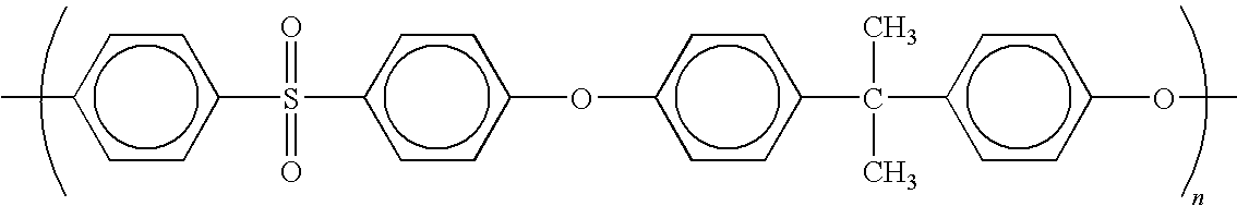 |
| Polyphenylsulfone (Radel R ®) |
 |
| Polyethersulfone (Radel A ®) |
 |
| Polyether sulfone (Ultrason E ®) |
 |
| Poly(hexafluoroisopropylidine dianhydride/meta phenylene diamine) |
 |
| Poly(triphenylphosphine oxide sulfide- phenylsulfone-sulfide) |
 |
| Poly(2-phenylsulfide-1,4-phenylene) |
 |
| Poly(hexafluoroisopropylidene dianhydride/diaminodiphenyl sulfone) |
 |
| (PVSA) polyvinyl sulfonic acid |
|
| Poly(hexafluoroisopropylidene dianhydride/diaminodiphenoxybenzene) |
 |
| Poly-X ® (Maxdem) |
 |
| Poly(pyrolmellitic diimide-1,3-phenylene) |
 |
| Poly(diphthalimide-1,3-phenylene) |
 |
| (PPO) poly(1,4-phenylene oxide) |
|
| Diphenyl PPO (poly(2,6-diphenyl-1,4- phenylene oxide) |
 |
| PBPS (poly(benzophenone sulfide)) |
 |
| Poly(benzophenone sulfide- phenylsulfone-sulfide) |
 |
| Poly(acrylic acid) |
|
| Poly(trifluorostyrene sulfonic acid) |
 |
| Poly(vinyl phosphonic acid) |
|
| Poly(styrene sulfonic acid) (PSSA) |
 |
| TABLE 5 | ||||||||||
| 1 M Me(OH) | ||||||||||
| Permeability | ||||||||||
| (×10−6) | Dim. | |||||||||
| Thickness | % Dry Vol | Water | Resistance | Moles CO2 per | Stability | |||||
| Serial | ICP Type | ICP | (mils) | ICP | IEC | Content | (ohm * | Peroxide | min per cm2 | (% Area |
| Number | (ID) | (% wt) | Dry | Wet | (Estimated) | (meq./g) | (%) | m2) | Test | per mil | Change) |
| Nafion | Nafion 117 | 100 | 7.1 | 8.7 | 100 | 0.90 | 38 | 0.203 | −3.2% | 1.74 | ~20% |
| 117 | (1100 EW) | ||||||||||
| Control | |||||||||||
| FMI | 75% SPSU | ~30 | NT | 1.5 | 49 | 0.55 | 45 | 0.056 | NT | NT | NT |
| 539-22-1 | (Udel) | ||||||||||
| FMI | 75% SPSU | ~30 | NT | 1.5 | 49 | 0.96 | 55 | 0.043 | NT | NT | NT |
| 539-22-2 | (Udel) | ||||||||||
| FMI | 100% | ~30 | NT | 2.0 | 49 | NT | NT | NT | NT | 0.187 | NT |
| 539-22-3 | SPSU | ||||||||||
| (Udel) | |||||||||||
| FMI | 75% SPES | 12 | 2.0 | 3.1 | 29 | 0.23 | 27 | 127.0 | −38% | NT | NT |
| 126-08E | (Ultrason | ||||||||||
| E) | |||||||||||
| FMI | 75% SPES | 8 | 1.6 | 1.8 | 19 | 0.07 | 30 | 2177.1 | −36% | NT | NT |
| 126-08F | (Ultrason | ||||||||||
| E) | |||||||||||
| FMI | 1100 EW | 10 | 0.8 | 0.9 | 16 | 0.29 | 43 | 1290.8 | NT | NT | nil |
| 126-16N | (DuPont) | ||||||||||
| FMI | 1100 EW | 10 | 0.9 | 1.0 | 16 | 0.39 | 32 | 1183.2 | NT | NT | nil |
| 126-16O | (DuPont) | ||||||||||
| FMI | 150% | 20 | 1.1 | 3.5 | 40 | 0.82 | 87 | 5.11 | NT | NT | nil |
| 126-17P | SPPSU | ||||||||||
| (Radel R) | |||||||||||
| FMI | 100% | 20 | 1.2 | 2.5 | 40 | 0.62 | 60 | 16.60 | NT | 0.073 | nil |
| 126-17Q | SPPSU | ||||||||||
| (Radel R) | |||||||||||
| FMI | 150% | 20 | 2.1 | 4.7 | 40 | 0.54 | 90 | 1.85 | −63% | NT | nil |
| 126-18T | SPPSU | ||||||||||
| (Radel R) | |||||||||||
| FMI | 100% | 20 | 3.1 | 3.7 | 40 | 0.50 | 92 | 16.34 | −56% | 0.179 | nil |
| 126-18U | SPPSU | ||||||||||
| (Radel R) | |||||||||||
| FMI | 200% | 20 | 1.2 | 2.0 | 94 | 1.66 | 138 | 0.292 | NT | NT | nil |
| 126- | SPPSU | ||||||||||
| AY1 | (Radel R) | ||||||||||
| FMI | 1100 EW | ~17 | 2.0 | 2.5 | 40 | 1.16 | 47 | 0.637 | NT | NT | nil |
| 126- | (Dupont) | ||||||||||
| 79BB | |||||||||||
| FMI | 200% | 20 | 1.0 | 1.5 | 94 | 0.91 | 143 | 0.140 | NT | 0.261 | nil |
| 126- | SPPSU | ||||||||||
| 82BE | (Radel R) | ||||||||||
| FMI | 200% | 8 | 1.1 | 2.0 | 79 | 1.13 | 64 | 0.263 | NT | NT | nil |
| 126- | SPPSU | ||||||||||
| d91BO | (Radel R) | ||||||||||
| NT = NOT TESTED | |||||||||||
The polymers described herein are commercially available from a variety of suppliers (unless otherwise indicated). Suppliers of these polymers include the following: RTP, Ticona, Alpha Precision, Polymer Corp., Amoco Polymers, Greene Tweed, LNP, Victrex USA, GE Plastics, Norton Performance, BASF, Mitsui Toatsu, Shell, Ashley, Albis, Phillips Chemical, Sumitomo Bake, Sundyong, Ferro, Westlake, M. A. Hanna Eng.
The following procedures were employed in the fabrication and testing of samples that were prepared in accordance with the membranes and methods of this invention.
General Procedures
IEC Procedure
1. Cut out pieces of sulfonated films (target weight 0.2 g, target film thickness 2 mils).
2. Vacuum dry films at 60° C., record dry weights and note if films are in H+ or Na+ form.
3. Boil deionized water in separate beakers on hotplate.
4. Place films into boiling water.
5. Boil films vigorously for ½ hour.
6. Prepare 1.5N H2SO4.
7. Place films into H2SO4 and soak for ½ hour.
8. Remove films and rinse with deionized water.
9. Boil in deionized water again. Repeat until the films have soaked in H2SO4 three times.
10. Remove films from boiling water, pat film surface with paper towel, and rinse carefully with deionized water.
11. Place films in another beaker of water and check for pH.
12. Continue to rinse the films with water until pH is neutral to remove any excess acid trapped in the folds of the film.
13. Prepare saturated NaCl solution.
14. Boil the NaCl solution, pour into screw cap vials, add film and cap.
15. Place capped vials with film into water bath at 90° C. for 3 hours.
16. Remove capped beaker from water bath and cool to room temperature.
17. Remove the films from NaCl solution by pouring the salt solution into another beaker (save), wash the films with deionized water (save all washings—they will be used for titration).
18. Titrate the NaCl solution with 0.1N NaOH.
19. Take the films, pat with paper towel and take wet weight. (Use wet weight to determine water content of films.)
20. Dry the films under vacuum at 60° C. until constant weight.
21. Take dry weight and use this to calculate IEC.
Peroxide Test Procedure
22. Place films into the H+ form by following steps 1-12.
23. Make peroxide solution by adding 4 ppm Fe to 3% hydrogen peroxide (28.5 mg of ammonium iron (II) sulfate hexahydrate per liter of peroxide obtained from Aldrich).
24. Place the peroxide solution into water bath at 68° C.
25. Add films to the peroxide solution already at 68° C.
26. Peroxide test for 8 hours and record film properties (mechanical, color, handling etc.).
27. If film passes, remove from peroxide, rinse with water to remove all traces of peroxide solution.
Follow steps 13-21 to obtain post-peroxide test IEC.
Crosslinking Procedures
Ion-conducting polymeric samples can be crosslinked in the acid (H+) form to improve ICP stability. Normally, crosslinking is performed in vacuum, to exclude oxygen from the system (which can cause ICP charring). The vacuum oven should be preheated to temperatures of at least about 200° C. The ICP sample is then heated in the vacuum oven for a prolonged period of time. The ICP sample should be tested before and after crosslinking for IEC and peroxide stability in order to evaluate long term membrane stability. See e.g., Example 15 below.
Film Fabrication Procedures
Film Casting:
Unoriented, microporous substrate films can be made by dissolving the polymer in a suitable water miscible solvent and casting onto a glass plate or other surface. For example, dry PBO polymer can be dissolved in methanesulfonic acid (MSA). The films are slowly placed into a water bath, where solvent is rinsed from the films forming microporous, water-swollen membranes of PBO polymer. Subsequent washing allows for removal of all traces of the solvent.
Extrusion:
In general, the extrusion of a polymer solution (in a water miscible solvent) followed by its coagulation and washing in a water bath allows the formation of microporous polymer films. The mechanical properties and porosity are controlled by the characteristics of the polymer solution and the details of the extrusion process.
Microporous, biaxially-oriented films of liquid crystal polymers (LCPs) can be produced using a counter-rotating die (CRD) extrusion process. Solutions of the polymer are extruded using two annular and concentric mandrels that rotate in opposite directions. The rotation of the mandrels creates a transverse shear flow that is superimposed on the axial shear developed as the polymer solution is extruded through the die. The angle that the LCP fibrils make with the longitudinal axis of the tubular extrudate is ±θ, where θ can be varied from near-zero to about 65 degrees. The die rotation presets the biaxial (±θ) orientation of the emerging extrudate.
Subsequent post-die blowout (radial expansion) and draw (extrusion direction stretching) are used to further adjust and enhance the biaxial orientation.
The tubular extrudate leaving the die is expanded radially (blown) with pressurized nitrogen and stretched in the machine direction by pinch rolls to achieve the desired film thickness. The blown and drawn PBO bubble is immediately quenched in a water bath where the film structure is coagulated, or “locked-in-place”, and the polyphosphoric acid is hydrolyzed into phosphoric acid. The PBO film is collected under water on a spool, which is later transferred to a fresh water storage tank where it is thoroughly rinsed and stored in the water-swollen state until needed.
See e.g., U.S. Pat. No. 4,963,428.
Hot Pressing of LCP Membranes
A slug of LCP dope of a mass sufficient to yield a film of desired thickness and diameter is placed between a sheet of Mylar and a sheet of Teflon, with shims of desired thickness on the perimeter. This assembly is made within a hinged clam mold resting inside a vacuum press. Once evacuated, the sample is pressed to 20,000 lbs. at up to 105-100° C. and held at these conditions for 10 minutes. Pressure is then maintained while the press and sample are cooled to room temperature at a 25 degree per minute rate. The sample is removed from the press, and the Teflon is peeled off before mounting the sample in tensioning rings and immersing it in water to coagulate it.
Solvent Exchange:
The water swollen microporous substrate is used to complete a staged “solvent” exchange. The initial solvent (100% water) is exchanged for the desired solvent (e.g. NMP, alcohol, etc.) in a number of stages. To minimize the collapse of the pores, the exposure of the substrate film to the air is minimized. For example, note the 5 part exchange from water to NMP as follows:
| START | FINISH | |
| Exchange #1: | 100% Water | 75% Water/25% NMP |
| Exchange #2: | 75% Water/25% NMP | 50% Water/50% NMP |
| Exchange #3: | 50% Water/50% NMP | 25% Water/75% NNP |
| Exchange #4: | 20% Water/80% NMP | 100% NMP |
| Exchange #5: | 100% NMP | Fresh (anhydrous) NMP |
Microporous substrate films are stored in the exchanged solvent until they are used in composite SPEM formation.
Sulfonation Procedures
Sulfonation Procedure I:
Aromatic PES polymers can be sulfonated to controlled degrees of substitution with sulfonating agents. The degree of substitution is controlled by the choice of and mole ratio of sulfonating agent to aromatic rings of the polymer, by the reaction temperature and by the time of the reaction. This procedure offers a method for carrying out sulfonation in a heterogeneous manner, i.e., sulfonation of precipitated polymer crystals.
The polymer (preferably a polyethersulfone) is first dissolved in the appropriate solvent (preferably methylene chloride) and then allowed to precipitate into a fine crystalline suspension. Sulfonation is carried out by simple admixture of the suspension with a sulfonating agent. Suitable agents include chorosulfonic acid and, preferably, sulfur trioxide (Allied chemicals stabilized Sulfan B® in CH2Cl2). The sulfonating agent used should be in sufficient proportion to introduce a number of sulfonate groups onto the polymer that is within the range of between 0.4:1 to 5:1 per polymer repeat unit, although this is not critical. The temperature at which sulfonation takes place is critical to limiting the side reactions but varies with the type of polymer (a preferable temperature is within the range of from −50° to 80° C., preferably −10° to +25° C.).
When the desired degree of sulfonation has been reached, the sulfonated polymer may be separated from the reaction mixture by conventional techniques such as by filtration, washing and drying.
The polymer products of the process of the invention may be neutralized with the addition of a base, such as sodium bicarbonate, when desired and converted to the alkali salts thereof. The alkali salts of the polymer products of the invention may be used for the same purposes as the parent acid polymers.
See e.g., U.S. Pat. No. 4,413,106.
Sulfonation Procedure II:
Concentrated sulfuric acid is used as the solvent in this procedure. The content of the sulfonating agent, sulfur trioxide, is based on the total amount of pure (100% anhydrous) sulfuric acid present in the reaction mixture, and is kept to a value of less than 6% by weight throughout the entire sulfonation. The sulfur trioxide may be mixed in dissolved form (oleum, fuming sulfuric acid) with concentrated sulfuric acid. The concentration of the starting sulfuric acid and oleum were determined by measuring their density immediately before use in the reactions.
The temperature of the reaction mixture is kept at less than +30° C. throughout the reaction. The sulfonation procedure is stopped by pouring the reaction mixture into water.
More specifically, the polymer is first dried in high vacuum at room temperature to constant weight, then dissolved in concentrated sulfuric acid. Oleum is then added drop-wise over a period of hours with constant cooling below +30° C., and with stirring. When all of the oleum has been added, the reaction mixture is stirred for a further period of hours at the same temperature. The resultant viscous solution is then run into water and the precipitated polymer is filtered off. The polymer is then washed with water until the washings no longer are acidic, and it is then dried.
If these conditions are maintained, a controllable sulfonation of aromatic polyether sulfones is possible and polymer degradation can be substantially or completely prevented.
Though less preferred, another variation of this procedure is to add the sulfur trioxide either in pure solid state or in gaseous state to a solution of the polymer in concentrated sulfuric acid.
See e.g., U.S. Pat. No. 5,013,765.
Sulfonation Procedure III:
This sulfonation procedure is directly analogous to procedure I, however, the polymer remains in solution at least until the addition of the sulfonating agent.
Polymer is first dissolved in a solvent that is compatible with the sulfonating agent (e.g. methylene chloride) in a nitrogen atmosphere. The sulfonating agent is added to this solution over the course of several hours. The resulting solution or suspension (if the polymer precipitates as the reaction occurs) is allowed to react, again for several hours.
When the desired degree of sulfonation has been reached, the sulfonated polymer may be separated from the reaction mixture by conventional techniques such as by filtration, washing and drying. If the sulfonated polymer remains in solution, the solvent can be removed simply by evaporation or precipitation into a non-solvent.
Membrane Preparation
Microporous substrate films previously exchanged into the appropriate solvent are placed consecutively into solutions of the various ion-conducting polymers (ICP) with increasing concentration (in the same solvent as the unfilled microporous substrate). This technique is known in the art (see, e.g., U.S. Pat. No. 5,501,831). Generally the use of smaller changes in ICP concentration seems to allow the formation of composite films with higher final ICP loadings. In the case of more viscous polymer solutions, the microporous substrates and the imbibing solution are heated (up to 100° C.). Once imbibed with the ICP, the composite film is placed between 6″ diameter tension rings. As the rings are bolted together, the composite is carefully stretched to eliminate any veins or defects in the substrate. Once the rings are completely bolted together, the setup is left to air dry (e.g. in the hood) overnight. This will usually remove much of the excess ion-conducting polymer's solvent by evaporation.
The films are further dried by one of two methods. For low boiling solvents the composite films are heated under vacuum with pressure (about 100 psi) to prevent blistering of the films. In these instances porous, Teflon® coated shims are used to allow the solvent vapor to escape. Higher boiling composite films are simply heated under vacuum past the boiling point of the solvent. The overall uniformity of the final composite membrane can be improved by further pressing these composites at elevated temperature and pressure.
Composite Membrane Testing Methods
IEC. % Water Content, Membrane Degradation:
During this procedure, films are immersed in distilled H2O and boiled for a period of 30 minutes. The films are then placed in a solution of 1.5N H2SO4 at room temperature and soaked for a period of 30 minutes. This is repeated three separate times to ensure proper H+ ion exchange into the membrane. Films are rinsed free of acid (pH of rinse water >5.0) and placed into separate beakers, each filled with a saturated solution of NaCl. The salt solution is boiled for a period of three hours. The films, which are now in the Na+ form, are removed from the salt solution, rinsed with distilled water and padded to remove excess water. Now a wet weight and thickness of the sample are measured. While in the Na+ form, the films are dried in an air oven at a temperature of 60° C. The dry weight and thickness of the films are measured and the percent water content is calculated. The salt solutions are titrated with 0.1N NaOH to a phenolphthalein endpoint and IEC dry (meq/g) values calculated.
Ionic Conductivity:
Transverse ionic conductivity measurements are performed on film samples in order to determine the specific resistance (ohm*cm2). Prior to the ionic conductivity measurements, film samples are exchanged into the H+ form using the standard procedure discussed above. To measure the ionic conductivity, the film samples are placed in a die consisting of platinum-plated niobium plates. The sample size tested is 25 cm2. Prior to assembling in the measuring device, platinum black electrodes are placed on each side of the film sample to form a membrane-electrode assembly (MEA). To insure complete contact during the resistivity measurement, the MEA is compressed at 100 to 500 psi. The resistance of each film is determined with a 1000 Hz, low current (1 to 5A) bridge, four point probe resistance measuring device and converted to conductivity by using formula 1.
C=t/R×A (1)
C=t/R×A (1)
-
- Where: C=Conductivity (S/cm)
- R=Sample Resistance (ohm)
- t=Wet sample thickness (cm)
- A=Sample area (cm2)
- Where: C=Conductivity (S/cm)
Measurements are converted to specific resistance by calculating the ratio of thickness over conductivity (ohm*cm2).
Membrane Degradation:
Accelerated degradation testing is carried out using 3% H2O2 solution with 4 ppm Fe++ added as an accelerator. The films are tested for a period of 8 hours at a temperature of 68° C. The percent degradation of IEC was measured in the film samples after the test. After 8 hours, the films are removed from solution, and re-exchanged using 1.5 N H2SO4. The IEC is recalculated, and the test result expressed as the % loss in IEC. This test simulates long term (several thousand hours) of actual fuel cell operation. For H2/O2, fuel cells, <10% IEC degradation in this test would be considered acceptable.
Sulfonation of Radel R®
Using Sulfan B® (100% and 150% Stoichiometric Sulfonation)
Sulfonation Procedure I was used in the following example.
Two separate 1000 ml 3 neck resin kettles (with ribs) equipped with an N2 inlet, addition funnel, and overhead stirrer were charged with the following reactants: 340 ml of dichloromethane and 50.00 grams of Radel R® Polyphenylsulfone Polymer (beads). These mixtures were stirred until solutions formed (approximately 0.25 hours). Once solutions formed, they were cooled in ice baths to about a temperature of 0° C. (ice bath was maintained throughout the duration of the addition and reaction). (Note that Radel R® was dried at 70° C. under full dynamic vacuum for about 12 hours to remove any adsorbed moisture.)
While the above solutions were cooling, the following amounts of Sulfan B® were combined with dichloromethane in two separate 125 ml addition funnels. In funnel #1 (100% sulfonation) 10.00 grams of Sulfan B® was combined with 120 ml of dichloromethane. In funnel #2 (150% sulfonation) 15.00 grams of Sulfan B® was combined with 120 ml of dichloromethane.
As polymer solutions were cooled, the polymer precipitated from solution to form a viscous paste. To each of these polymers approximately 350 ml of dichloromethane was added to aid in the uniform mixing of the suspensions. The diluted suspensions were then cooled to ice bath temperatures once again.
To the rapidly stirring cooled and diluted polymer suspension, the Sulfan B® solutions were added drop-wise over a period of 3.5 to 4.0 hours.
Upon completing the addition of the Sulfan B®/dichloromethane solution, the reaction mixtures were permitted to stir at ice bath temperatures for another 2.5 hours, then the reaction was stopped by adding approximately 10 ml of deionized water to each of the reaction mixtures.
The reaction mixtures (white dispersions) were recovered by filtration using a glass frit. Products (white powder) were washed 3× with 100 ml portions of dichloromethane. The washed products were then permitted to air dry in the hood. 20% solutions of the dried products were made in NMP and cast on soda lime glass plates. The freshly cast films were left to stand in a dry box with a relative humidity of less than 5% for a period of 24 hours. The cast films were heated at 70° C. under full dynamic vacuum for an hour prior to floating the films off with deionized water. The floated films were then permitted to air dry overnight.
The 100% and 150% sulfonated products swell greatly in water and become opaque, but when films are dry they shrink and become clear once again. The mechanical strength of these films allows creasing while resisting tearing. Films of the 100% and 150% products are not soluble in boiling water, and under these conditions also maintain their mechanical properties.
-
- IEC: 100% sulfonated Radel R® unpurified=1.39 meq./g
- 150% sulfonated Radel R® unpurified=1.58 meq./g
- IEC: 100% sulfonated Radel R® unpurified=1.39 meq./g
These polymers were further purified by dissolving in NMP (at 20 wt. %) and then precipitated into a large excess of saturated salt water. The resulting polymers were soaked in sodium bicarbonate, washed several times with water, then dried under vacuum (˜100° C.). These polymers were also cast into films as described above for characterization.
-
- IEC: 100% sulfonated Radel R® purified=1.26 meq./g
- 150% sulfonated Radel R® purified=1.44 meq./g
- Water Pick-up (wt. %):
- 100% sulfonated Radel R® purified=56%
- 150% sulfonated Radel R® purified=110%
- IEC: 100% sulfonated Radel R® purified=1.26 meq./g
Sulfonation of Radel R®
Using Sulfan B® at 200% Stoichiometric Sulfonation
Procedure:
This sulfonation reaction was run very similarly to those previously described in Example 1 (100, 150% sulfonations with Sulfan B®), with minor adjustments, which are noted below:
After the precipitation of the polymer from the initial dichloromethane solutions, only 200 ml of new solvent was added to enhance stirring (in Example 1, an additional 350 ml was used).
Previous data suggests that not all of the SO3 reacts with the polymer over 6 hours at 0-5° C. Therefore, one reaction was carried out at ice bath temperatures for 8 (or more) hours and then allowed to warm to room temperature. Although the resulting sulfonated Radel R® was darker in color than the batch that was quenched after only 6 hours, the polymer was still water insoluble and showed good film properties. The properties of such ICPs are:
-
- 200% Sulfonated Radel R (quenched after 6 hrs at 0-5° C.):
- IEC=1.67 meq/g, Water Pick-up=144%, Conductivity=0.073 S/cm.
- 200% Sulfonated Radel R (quenched after allowed to warm up):
- IEC=1.90 meq/g, Water Pick-up=174%, Conductivity=0.091 S/cm
A similar reaction was carried out in which the SO3 was allowed to react longer, but was kept cold (0-5° C.) throughout the reaction. The product isolated from this reaction had an IEC value (1.71 meg/g) which was between the two batches described above.
Note: Percent sulfonation in terms of stoichiometry, e.g., 200% sulfonation, refers to the use of a particular excess per each polymeric repeat unit, e.g., two moles in the case of 200% sulfonation.
Sulfonation of BASF Ultrason® Polyether Sulfone
Using Sulfan B®
(85%, 75%, and 65% Sulfonation)
Sulfonation Procedure III was used in the following example.
Three separate 1000 ml 3 neck resin kettle (with ribs) equipped with an N2 inlet, addition funnel, and overhead stirrer were charged with the following reactants: the first resin kettle was charged with 350 ml of dichloromethane and 51.00 grams of BASF Ultrason polyether sulfone polymer (fine powder), the second was charged with double the amount of reactants, and the third was charged with the same ratios as the first. Ultrason was dried at 70° C. under dynamic vacuum for about 12 hours prior to use. These mixtures were stirred until solutions formed (approximately 15 min.). Once solutions formed, they were cooled in ice baths to about a temperature of 0° C. (ice bath was maintained throughout the duration of the addition and reaction).
While the above solutions were cooling, the following amounts of Sulfan B® were combined with dichloromethane in three separate 125 ml addition funnels. In funnel #1 (85% sulfonation) 14.94 grams of Sulfan B® were combined with 120 ml of dichloromethane. In addition funnel #2 (75% sulfonation) 26.32 grams of Sulfan B® were combined with 120 ml of dichloromethane. In addition funnel #3 (65% sulfonation) 11.80 grams of Sulfan B® were combined with 120 ml of dichloromethane. These solutions were then added dropwise to the corresponding rapidly stirring cooled polymer solutions over a period of 4 hours.
Addition of the Sulfan B® solution caused the polymer to precipitate and form a very viscous sludge. These were diluted with the following amounts of anhydrous dichloromethane. Reaction #1 was diluted with 70 ml of anhydrous dichloromethane, #2 was diluted with 600 ml of dichloromethane, and #3 was diluted with 400 ml of dichloromethane. Upon completing the addition of the Sulfan B®/dichloromethane solution, the reaction mixture was permitted to stir and warm to room temperature overnight. The following morning the reaction mixtures (a white dispersion) were filtered using a glass frit. Products (a fine white powder) were washed 3× with 100 ml. portions of dichloromethane. The washed products were then permitted to air dry in the hood for 4 hours.
20 wt. % solutions of the dried products were made in NMP. The polymer solutions were filtered using a 2.5 micron glass fiber filter cartridge. The filtered products were then precipitated into approximately 4 liters of water. These products were then washed 2× with deionized water. The washed products were converted into the sodium form by soaking in a 2.5% sodium hydroxide solution over several days. These were then washed with deionized water until a neutral pH was achieved. Finally, the samples were thoroughly dried in vacuum.
When 85% sulfonated polymer is boiled in water, it swells greatly and partially dissolves. The 75% and 65% sulfonated products do not dissolve in boiling water, however they showed considerable swelling.
-
- IEC: 65% sulfonated Ultrason purified=0.69 meq./g
- 75% sulfonated Ultrason purified=0.80 meq./g
- 85% sulfonated Ultrason purified=1.08 meq./g
- Water Pick-Up (wt. %):
- 65% sulfonated Ultrason purified=18%
- 75% sulfonated Ultrason purified=21%
- IEC: 65% sulfonated Ultrason purified=0.69 meq./g
Synthesis of Sulfonated Udel® Polyether Sulfone
Using Chlorosulfonic Acid (33-100% sulfonation)
Sulfonation Procedure III was used in the following example.
Procedure:
A 1000 ml. 3 neck round bottom flask equipped with a condenser, N2 inlet, and overhead stirrer; was charged with 175 ml of dichloromethane and 50.0 grams of Udel® Polyethersulfone. This mixture was stirred until a solution formed (approximately 3 hours).
While the above was stirring 11.49 grams of chlorosulfonic acid was mixed with 50 ml. of dichloromethane in a 125 ml. addition funnel. This solution was added dropwise to the rapidly stirring polymer solution over a period of an hour. The reaction mixture changed from a clear amber color to a cloudy caramel color. Upon completing the addition the acid solution, the reaction mixture was permitted to stir at room temperature over night.
After stirring at room temperature for 28 hours the reaction mixture was heated in a water bath until a mild reflux was achieved, and it was kept refluxing under these conditions for an hour. After heating the reaction mixture for an hour the heat source was removed and the mixture was permitted to cool.
After removal of the solvent, the product was dissolved in THF. Films cast from this solution were transparent and creasible. IR spectra and water absorption were consistent with the formation of sulfonated Udel® Polyethersulfone.
Complete reaction of the chlorosulfonic acid corresponds to the addition of 0.85 sulfonate groups per repeat unit of the polymer (85%). Similarly, sulfonated versions of Udel® Polyethersulfone were made with levels of sulfonation from 33 to 100%.
-
- IEC: 75% sulfonated Udel=1.10 meq./g
- 85% sulfonated Udel=1.19 meq./g
- Water Pick-up (wt. %):
- 75% sulfonated Udel=12%
- 85% sulfonated Udel=93%
- IEC: 75% sulfonated Udel=1.10 meq./g
Synthesis of Sulfonated-Polyimides
(via Monomers)
Sulfonation procedures described by Sillion [French patent 9,605,707] were used as a guide in the following example. However, alternate monomers and reaction conditions were employed.
Sulfonated polyimides are produced by the reaction of a sulfonated diamine with a dianhydride, using a 1.000 molar ratio of diamine/dianhydride, in a solvent under an inert atmosphere. An exact diamine/dianhydride molar ratio of 1.000 is required in order to achieve high molecular weight polymers. Polyimides are synthesized through an intermediate polyamic acid form which contains an amide linkage and carboxylic acid groups. This polyamic acid may or may not be isolated from the reaction solution. The polyamic acid is converted to the corresponding polyimide by a cyclization reaction involving the amide hydrogen and neighboring carboxylic acid groups, forming a five (or six) membered imide ring, with the evolution of water as a reaction byproduct.
Polyimides can be made via two general procedures: 1) first synthesize, at or below ambient temperatures its solvent-soluble polyamic acid form, then chemically or thermally transform this polyamic acid to the polyimide; and 2) directly synthesize the solvent-soluble polyimide using reaction temperatures in excess of 100° C. to distill water from the initial reaction solution. Each of these procedures was used at Foster-Miller to produce sulfonated-polyimides. The details of these reactions are presented below.
2,4-Diaminobenzenesulfonic acid (2,4-DBS) (5.00 grams, 26.6 mmoles) was dispersed in 95.29 grams anhydrous methanol at ambient temperatures under a positive nitrogen atmosphere in a reaction flask equipped with a reflux condenser, magnetic spinbar for stirring purposes and pressure equalizing funnel. A cloudy dispersion of sodium hydroxide (1.06 grams, 26.6 mmoles) in methanol (93.4 grams) at a concentration of 1.1 wt. percent was placed in the pressure equalizing funnel and added dropwise to the stirring 2,4-DBS/methanol dispersion at ambient temperatures. Additional methanol (195 grams) was added to transform the dispersion into a brownish orange colored solution after stirring overnight, containing approximately 1.3 wt. percent solids. Initially, 2,4-DBS was found to be insoluble at similar concentrations in methanol, indicating 2,4-DBS has been converted into a more soluble material. The solution was heated at reflux for several hours to ensure the reaction had gone to completion, cooled to ambient temperatures, and filtered to remove any trace amounts of undissolved material. Hexanes (275 mL) were then added to the solution to precipitate a tannish solid. This solid was collected by filtration, washed with hexanes and air dried. The material exhibited a single reproducible endothermic absorption between 246° to 252° C., with a peak width at half height of 5.3° C. by differential scanning calorimetry. Its infrared spectrum (IR) showed absorptions typical for a —NH2 amine (3426, 3380, and 3333 cm−1), a primary amine (3199 cm−1), aromatic C-Hs (1624 cm−1) and SO3 salt (1230 and 1029 cm−1) groups. These SO3 salt absorptions were located at values different than those observed for HOSO2 in 2,4-DBS, which appeared at 1302 and 1134 cm−1. The amine absorption at 3426 cm−1 in this material was also not present in 2,4-DBS. The IR absorption typical for a sulfonic acid (—SO2—OH) group at 2609 cm−1 in 2,4-DBS was also absent. The combination of all this information indicates the tannish solid product is sodium 2,4-diaminobenzenesulfonate (2,4-NaDBS).
This material was be used as an alternative to 2,4-DBS in the synthesis of sulfonated polyimides due to its increased thermal stability and potentially increased reactivity toward polyimide formation (amine groups in the 2,4-NaDBS are more reactive toward the dianhydride monomer due to electron release from the sulfonate group).
2,4-DBS (7.75 mmoles) and m-PDA (7.75 mmoles) were easily dissolved in anhydrous dimethylsulfoxide (DMSO) at ambient temperatures under a nitrogen atmosphere. 6FDA (15.5 mmoles) was added all at once to the diamine solution and the mixture was stirred at ambient temperatures under a nitrogen atmosphere. The reaction mixture became warm to the touch as the 6FDA began to dissolve and the resulting, solution was stirred overnight at ambient temperatures. This clear reddish brown solution contained 15.0 wt. percent polymer and exhibited a viscosity similar to warm syrup, indicating polymers with reasonable molecular weights had been produced. The IR spectrum of the reaction solution showed absorptions typical for —NH of an amide (3249 and 3203 cm−1), C=0 amide I stretch (1683 cm−1), aromatic C-Hs (1607 cm−1), N—C=0 amide II symmetric stretch (1548 cm−1) and SO3 salt (1256 and 1020 cm−1). The IR absorption for —OH of HOSO2 at 2609 cm−1 was absent from the spectrum. This IR data is consistent with the formation of the 6FDA/m-PDA/2,4-NaDBS copolyamic acid.
A sample of the polyamic acid solution was cast into a film on a NaCl salt IR disc and the film/disc was heated in a circulating air oven for 1 hour each at 100°, 200° and 300° C. to convert the copolyamic acid to its copolyimide form. The IR spectrum of copolyimide film showed absorptions typical for C=0 imide stretch (1787 and 1733 cm−1), aromatic C—H (1603 cm−1), C—N imide stretch (1362 cm−1), HOSO2 acid (1298 and 1145 cm−1), SO3 salt (1256 and 1029 cm−1) and polyimide (745 and 721 cm−1). IR absorptions typical for polyamic acids at 1683 and 1545 cm−1 as well as the —OH of HOSO2 at 2609 cm−1 were absent. Nevertheless, it appears that some of the NaSO3 groups were converted to HOSO2 by free acid generated during the continuing polymerization.
A sample of the reaction solution was cast into a large film with an initial thickness of 0.007 inch on a glass substrate using a motorized film casting table located inside a low humidity chamber (<10 percent relative humidity). The resulting clear copolyamic acid film was heated in a circulating air oven for 1 hour each at 100°, 200°, and 250° C. to form a reddish brown copolyimide film. A final temperature of 250° rather than 300° C. was used to hopefully reduce the thermal degradation of the resulting NaSO3 groups, believed to occur at temperatures >200° C. The copolyimide film broke into many very small pieces upon removal from the glass substrate, a sign that the molecular weight of the copolyimide may be quite low.
Synthesis of the Copolyimide Directly from 6FDA, m-PDA, and 2,4-NaDBS (6FDAlm PDA12,4-NaDBS PI) A brownish dispersion of 2,4-NaDBS (7.47 mmoles) and m-PDA (8.01 mmoles) in m-cresol (50 grams) and anhydrous toluene (20 grams) in a 3-necked flask equipped with a thermometer, mechanical stirrer, and Dean Stark trap fitted with a condenser/nitrogen inlet was heated at about 150° C. under a nitrogen atmosphere. 6FDA (15.49 mmoles) was added to the hot dispersion, whereupon water immediately began to distill out of the reaction dispersion and become collected in the trap. The temperature of the brownish dispersion was gradually increased to about 200° C., maintained at 200° C. for 7.5 hours, and then decreased to ambient temperatures. The resulting dark brown colored, viscous reaction mixture was found to be a dispersion containing significant quantities of crystalline material(s). The IR spectrum of the reaction dispersion showed absorptions typical for or C=0 imide stretch (1781 and 1723 cm−1), C—N imide stretch (1365 cm−1), SO3 salt (1251 and 1033 cm−1), and polyimide (738 and 720 cm−1). The presence of m-cresol in the film prevents determination of whether HOSO2 groups are present due to overlapping absorptions. IR absorptions typical for polyamic acids at 1683 and 1548 cm−1 as well as the OH stretch of HOSO2 were absent. IR data indicated some sodium sulfonate-copolyimide had been produced under the reaction conditions, but the presence of a crystalline dispersion rather than solution suggests a significant amount of the diamine was not incorporated into a polymer.
The consistent problem encountered during these reactions was low molecular weight of the final product. The above syntheses did not provide a creasable, sulfonated polymer film. However, fragments of the polymer are unchanged by the peroxide test and have IECs up to 1.13 meq./g.
It is anticipated that higher molecular weight polymer will be obtained by further purifying the 2,4-NaDBS monomer prior to polymerization. In addition, the use of isoquinoline as a polymerization catalyst may accelerate the reaction.
Sulfonation of Victrex® Poly(Ether Ketone)
Using H2SO4/SO3
Sulfonation Procedure II was used in the following example.
Procedure:
30.00 g PEK polymer (Victrex®) was dissolved in 270 g of concentrated sulfuric acid (93.5 wt. %) under nitrogen, stirred by an overhead mechanical stirrer. The polymer was dispersed over several days to form a dark red thick solution.
176 g of this solution was left in the three neck flask with overhead stirrer, N2, etc. To the flask, 208.4 g of fuming sulfuric acid (25.5 wt. % free SO3) was added over the coarse of a few minutes with constant stirring to raise the solution to a free SO3 content of 2 wt. %. The resulting solution was immersed in a room temperature water bath to control the temperature.
Samples were removed after approx. 1 hour, 3 hours, and 16 hours, and quenched into deionized water to precipitate.
In order to make films, the 1 and 3 hour products were washed several times with deionized water, soaked overnight in approximately 0.5M NaOH solution, then washed until a neutral pH was achieved. These were blotted dry and placed in the vacuum oven overnight at 50° C. Dried samples were dissolved in NMP to make a 20 wt. % solution. This required heating overnight at 60° C. Films of approx. 6 mils were cast onto a freshly cleaned glass plate. After two days of drying the films were removed by immersion into deionized water.
Soaking the films in water (at room temperature) caused considerable swelling to give a hazy gel-like consistency, but the 1 hour and 3 hour samples did not dissolve. Film of the 1 hour product could be hydrated and dehydrated, while maintaining resistance to tearing. The 1 hour sulfonated PEK film IEC was measured to be 2.3 meq/g.
Sulfonation of PPS/SO2 Using 97.5% H2SO4
Sulfonation Procedure II was used in the following example.
PPS/SO2 provided by James McGrath of VPI [see Synthesis and Characterization of Poly(Phenylene sulfide—sulfone). Polymer Preprints 38 (1), 1997, p.109-112].
Procedure:
250 ml 3 neck round bottom flask was equipped with an overhead stirrer, N2 inlet, and addition funnel were charged with 100 grams of 93.5% sulfuric acid. To the rapidly stirring sulfuric acid 25.00 grams of the PPS/SO2 was added. The mixture was stirred at room temperature until a solution formed (approximately 1 hour).
When solution had formed the temperature was lowered to about 0° C., and 60.0 grams of 23.0% fuming sulfuric acid was added dropwise over a period.of a 0.5 hours.
Ice bath temperatures were maintained for the first 3.5 hours of the reaction. Aliquots were taken at T=0.5, 1.5, 2.0, and 3.0 hours by precipitation the reaction mixtures were precipitated into deionized water. Precipitated product appeared not to have swollen to any appreciable extent, so the remaining reaction mixture was warmed to room temperature. Aliquots were taken at t=3:30, 4:30, 7:00, and 8:20 (approximately 4 hours at room temperature).
Products were rinsed 3 times with deionized water, soaked in saturated sodium bicarbonate solution until basic and then washed in deionized water until neutral.
Solubilizing of the sulfonated PPS/SO2 polymers was attempted after drying the precipitated polymer at 100° C. for 3 hours under full dynamic vacuum. The polymer solutions were made with fresh anhydrous NMP and were immediately cast on soda lime glass plates at a thickness of 2 mils. The freshly cast films were placed in a level oven preheated to 100° C. and dried under full dynamic vacuum for 1 hour. After drying (at 100° C.) for an hour, the oven temperature was raised gradually to 200° C. over a period of 3 hours. When the 200° C. was achieved, the oven was shut off and the films were permitted to gradually cool to room temperature. Films were removed from the glass plates by floating them in deionized water.
Based on crude observations of the PPS/SO2 films, this material appears not to have sulfonated to any appreciable extent while kept at 0° C. (little dimensional changes were observed when boiled in water). The PPS/SO2 samples that were reacted at room temperature appear to show some signs of sulfonation (swelling and taking on a rubbery appearance in boiling water).
-
- IEC sulfonated PPS/SO2:
- T=8:20, 0.53 meq./g
- Water Pick-up (wt. %) sulfonated PPS/SO2:
- T=8:20, 15%
- IEC sulfonated PPS/SO2:
Increased IECs of the sulfonated PPS/SO2 samples should be possible with increased reaction times.
Sulfonation of Poly(phenylquinoxaline)
PPQ was prepared as described in the literature (See e.g., Macromolecular Syntheses, 1974, vol. 5 p. 17), by dissolving equimolar amounts of an aromatic bisbenzildiketone and a bis-o-diamine in a 1:1 mixture of m-cresol and xylene. The resulting polymer was isolated by dilution with chloroform followed by precipitation into a large excess of methanol. The polymer was thoroughly washed with methanol and vacuum dried.
Sulfonation was achieved by first dissolving this polymer in concentrated sulfuric acid, followed by the addition of enough fuming sulfuric acid to react with any water remaining in the system (i.e. 100% H2SO4). The resulting solution was heated to 125° C. with constant stirring. Aliquots were taken over 6 hrs. at this temperature. Each aliquot was isolated by precipitation into water, soaking in saturated sodium bicarbonate, followed by several rinsings with deionized water. Sulfonation of the later aliquots was inferred from their enhanced solubility in polar solvent systems. Generally, films cast of the sulfonated PPQ (sodium salt form) are tough, creaseable, and swell in water.
Alternatively, a PPQ film can be soaked in a 50% solution of H2SO4 for approx. 2 hour in order to fully sulfate it; then baked at a minimum temperature of 300° C. to convert the ammonium sulfate salt to the covalently bonded sulfonic acid. This procedure has been used for the sulfonation of PBI and PPQ films. See e.g., U.S. Pat. No. 4,634,530 and Linkous, et al., J. Polym. Sci., Vol. 86: 1197-1199 (1998).
Fabrication of SPEM
Using PBO and Sulfonated Radel R®
Ion-conducting membranes were fabricated from the polymer substrate film PBO and various sulfonated poly(phenyl sulfones). The substrate utilized was PBO film extruded and solvent exchanged into NMP as described above in the general procedure. The ion-conducting polymer (100, 150% sulfonated Radel R®—Na+ form) was synthesized according to Example 1 given above.
Microporous PBO, having been exchanged into NMP without collapse of the pores, was added to a 5 wt. % solution of the sulfonated Radel R® polymers in NMP. After twelve or more hours, the films were removed and placed in a 20 wt. % solution of the same ion-conducting polymer (also in NMP). After twelve or more hours at room temperature (or at 75° C.) the films were removed, stretched in tensioning rings, and dried of the solvent (see general procedure outlined above). Specifically, the sulfonated Radel R®/PBO films were dried in a low humidity chamber (<5% RH) for 1 to 2 days, vacuum dried in an oven heated from below 60° C. to about 200° C.
After all solvent is fully extracted from the membrane, the composite is preferably hot pressed. The hot pressing operation facilitates flow of the ion-conductor to make a homogenous composite structure. Non-porous Teflon® shims were placed on each side of the composite membrane followed by Titanium shims. The entire setup is then loaded into a press and subjected to the following cycle:
| High Temperature Hot Press |
| Step | Temp. | Hold Time | Force | Ramp Rate |
| 1 | 392° F. | 5 min | 1.0 klb | 15 F/min |
| 2 | 392° F. | 15 min | 28.3 klb | N/A |
| 3 | 85° F. | 5 min | 28.3 klb | 25 F/min |
| Note that the 28.3 klbf corresponds to a press pressure of 1000 psi. | ||||
SPEMs produced via this example were FMI 126-17P, FMI 126-17Q, FMI 126-17T, FMI 126-17U. See Table 5 for various results obtained from SPEMs made via this procedure.
Fabrication of SPEM
Using PBO and Sulfonated Udel®
Ion-conducting membranes fabricated in this example followed closely those in Example 9.
The substrate utilized was PBO film extruded and solvent exchanged into THF as described above in the general procedure. The ion-conducting polymer (75, 85, 100% sulfonated Udel®) was synthesized according to Example 4 given above.
For composite SPEMs of 100% sulfonated Udel® ion-conducting polymer, microporous PBO films exchanged into THF were placed into 30 wt. % solutions of the polymer (in THF) at room temperature. After more than twelve hours, the films were stretched in tensioning rings and allowed to dry in a low humidity chamber. Final traces of the solvent were removed with the following vacuum pressing shown below.
Low Temperature Vacuum Pressing
| Step | Temp. | Hold Time | Force | Ramp Rate |
| 1 | 122° F. | 20 min | 2.9 klb | 15 F/min |
| 2 | 167° F. | 20 min | 2.9 klb | 15 F/min |
| 3 | 212° F. | 20 min | 2.9 klb | 15 F/min |
| 4 | 257° F. | 20 min | 2.9 klb | 15 F/min |
| 5 | 85° F. | 5 min | 2.9 klb | 25 F/min |
The force of 2.9 klb corresponds to a press pressure of 100 psi. Films were finally hot pressed without vacuum to fully consolidate the composite structure, as shown below.
High Temperature Hot Press
| Step | Temp. | Hold Time | Force | Ramp Rate |
| 1 | 317° F. | 30 min | 28.3 klb | 15 F/min |
| 2 | 85° F. | — | 28.3 klb | 25 F/min |
The force of 28.3 klb corresponds to a press pressure of 1000 psi.
Composite SPEMs were made with both 75 and 85% sulfonated Udelo ion-conducting polymers.
SPEMs produced via this example were FMI 539-22-1, FMI 539-22-2, FMI 539-22-3. See Table 5 for various results obtained from SPEMs made via this procedure.
Fabrication of SPEM
Using Solubilized Nafion® 1100 EW
Ion-conducting membranes fabricated in this example followed closely those in Example 9.
The substrate utilized was PBO extruded film and solvent exchanged into a mixture of water and alcohols (see below) as described above in the general procedure. The ion-conducting polymer used was solubilized Nafion® 1100 EW purchased from Solution Technologies (10 wt. % in a mixture of water and propanols). The solvent system used to exchange the PBO films was made to approximate that of the Nafion® solution.
Composite membranes were made by placing the exchanged films directly into the 10 wt. % Nafion® solutions. After twelve or more hours, these were removed and stretched into tensioning rings as described above. These films were dried in a low humidity chamber for at least 24 hours. Removal of the final traces of solvent were done by placing porous PTFE shims on each side of the composite membrane followed by the Titanium shims. This setup was then loaded into a vacuum press and subjected to the following cycle:
Low Temperature Vacuum Pressing
| Step | Temp. | Hold Time | Force | Ramp Rate |
| 1 | 125° F. | 20 min | 2.9 klb | 15 F/min |
| 2 | 170° F. | 20 min | 2.9 klb | 15 F/min |
| 3 | 215° F. | 20 min | 2.9 klb | 15 F/min |
| 4 | 274° F. | 20 min | 2.9 klb | 15 F/min |
| 5 | 85° F. | 5 min | 2.9 klb | 25 F/min |
The force of 2.9 klb corresponds to a press pressure of 100 psi. Films were finally hot pressed without vacuum to fully consolidate the composite structure, as shown below.
High Temperature Hot Press
| Step | Temp. | Hold Time | Force | Ramp Rate |
| 1 | 275° F. | 5 min | 1.0 klb | 15 F/min |
| 2 | 275° F. | 15 min | 28.3 klb | N/A |
| 3 | 85° F. | 5 min | 28.3 klb | 25 F/min |
The force of 28.3 klb corresponds to a press pressure of 1000 psi.
SPEMs produced via this example were FMI 126-16N, FMI 126-16O. See Table 5 for various results obtained from these SPEMs. The low IECs obtained from these films and the correspondingly high resistances are a function of the low loading of ion-conductor in the composite structure. It is anticipated that using more concentrated solutions of the ion-conductor in imbibing the substrate will lead to composite SPEMs of low enough resistances for the applications described. The stability of the lateral dimensions of these Nafion® based composite membranes presents a significant improvement over unsupported Nafion® 117 films (which show in plane dimensional changes on hydration of about 20%). Given the exceptional strength of the PBO substrate, the mechanical properties of the composites are well in excess of current state of the art fuel cell membranes.
Fabrication of SPEM
Using PBO and sulfonated Ultrason®
Ion-conducting membranes fabricated in this example followed closely those in Example 9. The substrate utilized was PBO film extruded and solvent exchanged into NMP as described above in the general procedure. The ion-conducting polymer (75% sulfonated Ultrason purified—Na+ form) was synthesized according to Example 3 given above.
Microporous PBO, having been exchanged into NMP without collapse of the pores, was added to a solution of the sulfonated 75% sulfonated Ultrason polymer in NMP (8 or 12 wt. %). After twelve or more hours at room temperature the films were removed, stretched in tensioning rings, and dried of the solvent (see general procedure outlined above). Specifically, the sulfonated Radel R®/PBO films were dried in a low humidity chamber (<5% RH) for 1 to 2 days, vacuum dried in an oven heated from below 60° C. to 140° C.
Low Temperature Vacuum Pressing
| Step | Temp. | Hold Time | Force | Ramp Rate |
| 1 | 125° F. | 20 min | 2.9 klb | 15 F/min |
| 2 | 200° F. | 20 min | 2.9 klb | 15 F/min |
| 3 | 275° F. | 20 min | 2.9 klb | 15 F/min |
| 4 | 390° F. | 20 min | 2.9 klb | 15 F/min |
| 5 | 85° F. | — | 2.9 klb | 25 F/min |
The force of 2.9 klb corresponds to a press pressure of 100 psi. Films were finally hot pressed without vacuum to fully consolidate the composite structure, as shown below.
After all solvent is fully extracted from the membrane, the composite is preferably hot pressed. The hot pressing operation facilitates flow of the ion-conductor to make a homogenous composite structure. Non-porous Teflon® shims were placed on each side of the composite membrane followed by Titanium shims. The entire setup is then loaded into a press and subjected to the following cycle:
High Temperature Hot Press
| Step | Temp. | Hold Time | Force | Ramp Rate |
| 1 | 390° F. | 15 min | 28.3 klb | 15 F/min |
| 2 | 85° F. | 5 min | 28.3 klb | 25 F/min |
The force of 28.3 klbf corresponds to a press pressure of 1000 psi.
SPEMs produced via this example were FMI 126-08E, FMI 126-08F. See Table 5 for various results obtained from SPEMs made via this procedure.
Fabrication of SPEM Using Cast PBO and Sulfonated Radel R®
Ion-conducting membranes can be fabricated as illustrated above in Example 12 with use of microporous PBO substrates obtained by the film casting techniques enumerated in the general procedures. These films were solvent exchanged from water into NMP, after the coagulation and rinsing. These microporous films were placed in ion conductor solutions (5-10 wt. % in NMP) and allowed to equilibrate for a day or more. Once infused with the ion conductor solution, the films were placed in tensioning rings and dried of the solvent. In the case of the sulfonated Radel R®/cast PBO films, samples were first dried in a low humidity chamber for 1 or more days at room temperature and then vacuum dried at 200° C.
After all the solvent had been dried from the membrane, the composite structure was hot pressed using methods similar to those in Example 9. SPEMs produced via this example were FMI 126-AY1, FMI 126-82BE and FMI 126-d91BO. See Table 5 for various properties of these composite membranes.
Fabrication of SPEM Using Microporous Poly(ether sulfone) Substrate and Nafion®1100EW Ion Conductor
A commercially available microporous membrane made of poly(ether sulfone) was obtained from Memtec (BTS-80), with a 0.02 micron pore size and an approximate porosity (void volume) of 80%. This microporous membrane was soaked in a Nafion® 1100 EW solution (water/alcohol solvent). A vacuum was drawn on the solution and film to degas and completely fill the pores. The film was then removed from the solution and vacuum dried (to approx. 100° C.). This process was repeated two more times, each time the film was added to the solution, vacuum degassed, and dried of solvent. Finally, the ion-conducting component was placed in the sodium salt form by soaking in saturated sodium bicarbonate solution by repeated rinsing followed by vacuum drying. Properties of a SPEM produced using the above method are shown for FMI 126-79BB in Table 5.
Crosslinking of Sulfonated PPSU
Ion-conducting polymeric samples can be crosslinked in the acid (H+) form to improve ICP stability. Normally, crosslinking is performed in vacuum, to exclude oxygen from the system (can cause ICP charring). For example, SPPSU was crosslinked in a vacuum oven preheated to temperatures of 200, 225 and 250° C. for durations of up to 8 hours. Under these conditions, samples showed a slight IEC loss (˜10%), and little improvement in long term stability (peroxide test). More severe conditions were employed by exposing samples to 250° C. in full vacuum for more than 20 hours. Peroxide testing did not show any considerable difference between SPPSU crosslinked films and SPPSU controls until heated for at least 32 hours. The SPPSU films crosslinked at 250° C. for 32 hours and 72 hours maintained their film integrity during the peroxide accelerated life test. The IEC of these test samples decreased significantly. Specifically, a loss of 63% (1.90 to 0.69 meg/g) for the 32 hour sample and a loss of 73% (1.90 meg/g to 0.51 meq/g) for the 72 hour crosslinked SPPSU films was calculated. It is anticipated that many of the SO3H acid groups form aromatic sulfone (Ar—SO2—Ar) crosslinks between polymer chains. This trend confirms that crosslinking (H+ form) of sulfonated polymers can be used to improve long term membrane stability.

Bis(3-sulfonato, 4-fluorophenyl)sulfone monomer was reacted with 4-4′-thiobisbenzene thiol in the presence of potassium carbonate to prepare SPSS-100 water soluble sulfonated poly(phenylene sulfide sulfone) polymer. A three-necked round-bottomed flask was equipped with a mechanical stirrer, nitrogen adapter and Dean-Stark trap with condenser. The flask was charged with 13.747 g (30 mmol) sulfonated difluorodiphenyl sulfone, 7.512 g (30 mmol) of 4,4′-thiobisbenzene thiol, 9.54 g (69 mmol) potassium carbonate, 32 ml of toluene and 60 ml of N-methyl pyrrolidinone. The mixture was then stirred under nitrogen at 155° C. for 8 hours. Any water that collected in the Dean-Stark trap was drained and the temperature was increased to 160° C. for 24 hours. The temperature was increased to 170° C. and heating was continued for another 24 hours. The reaction mixture was cooled and the polymer was precipitated from methanol. The polymer precipitant was filtered and dried at 100° C. under vacuum overnight. To clean the polymer, the solid was dissolved at about 4 wt % in water and dialyzed using 1K SpectraPor® dialysis tubing through three rinses over the span of two days. The cleaned polymer was dried again and weighed. Elemental analysis was used to confirm the identity of the polymer and found it to be a dihydrate. In order to exchange the polymer to its acid form, it was re-dissolved in water at 1 wt % and run through a column of Amberlyst® ion exchange resin. The cleaned and converted polymer was dried under vacuum at 100° C. Titration of the water soluble polymers gave the expected average ion exchange capacity (IEC) of 3.2 milliequivalents of H+/g of polymer (see Table 6) and thermogravimetric analysis (TGA) showed clean materials with the anticipated sulfonic acid groups lost at roughly 250° C.
| TABLE 6 |
| EC values of SPSS-100 batches |
| IEC | ||||
| (mequiv of | ||||
| Polymer | H+/g of | % from | ||
| # | polymer) | theoretical | ||
| 412-54-1 | 3.1 | 3.125 | ||
| 412-54-2 | 3.1 | 3.125 | ||
| 412-67-1 | 3.154 | 1.4375 | ||
| 412-74-1 | 3.241 | −1.28125 | ||
| 412-74-3 | 3.16 | 1.25 | ||
| 412-77-2 | 3.1 | 3.125 | ||
PEMs were prepared by an imbibing process during which porous unconsolidated PBO membranes were soaked in aqueous solutions of ICP. To imbibe with water-soluble ICP, PBO membranes were first tensioned in stainless steel rings. The films were then soaked in solutions 20 wt % ICP in water at 80° C. overnight. This allowed the ICP concentration in the membrane pores to reach equilibrium with the bulk solution concentration. The films were pulled out of the imbibing solution and excess surface ICP was removed. Any desired surface treatment was then performed. Surface treatment could include application of a thin layer by immersion of the PEM in a 2% Nafion/dimethyl acetamide (DMAc) solution. The samples were dried to 175° C. on a ramp and soak cycle (see below)
PEM Drying Cycle:
-
- 1. Ramp (1 deg/min) to 75° C. and soak for 60 minutes
- 2. Ramp(1 deg/min) to 100° C. and soak for 60 minutes
- 3. Ramp(1 deg/min) to 150° C. and soak for 60 minutes
- 4. Ramp(1 deg/min) to 175° C. and soak for 60 minutes
Collapse of the structure upon drying yielded a fully densified PEM. Weight calculations showed PEMs are comprised of an average of 50-60% ion-conducting polymer. Area specific resistance (ASR) was tested for the SPSS-100 imbibed PEMs and found to be between 90 and 240 mohms*cm2. These data indicate successful imbibition of the water soluble ICP into the PBO membranes.
PEMs were prepared by an imbibing process during which porous unconsolidated PBZT membranes were soaked in solutions of ICP. To imbibe with water-soluble ICP, PBZT membranes were first tensioned in stainless steel rings. The films were then soaked in solutions of water and 20 wt % ICP at 80° C. overnight. This allowed the ICP concentration in the membrane pores to reach equilibrium with the bulk solution concentration. The films were pulled out of the imbibing solution and any excess surface ICP was removed. Any desired surface treatment was then performed. Surface treatment could include application of a thin layer of Nafion® by immersion of the PEM in a 2% Nafion/DMAc solution. The samples were dried to 175° C. on a ramp and soak cycle (see below)
PEM Drying Cycle:
-
- 1. Ramp (1 deg/min) to 75° C. and soak for 60 minutes
- 2. Ramp(1 deg/min) to 100° C. and soak for 60 minutes
- 3. Ramp(1 deg/min) to 150° C. and soak for 60 minutes
- 4. Ramp(1 deg/min) to 175° C. and soak for 60 minutes
Collapse of the structure upon drying yielded a fully densified PEM. Weight calculations showed PEMs are comprised of an average of 60-70% ion conducting polymer. ASRs for the SPSS-100 imbibed PEM's were found to be between 90 and 240 mohms*cm2. These data indicate successful imbibition of the water soluble ICP into the PBZT membranes.
PEMs were prepared to compare the use of SPSS-100, a water soluble polymer to SPES-40, an organic solvent-soluble polymer as the imbibed ion-conducting polymer in PBO substrates. These PEMs were evaluated for conductivity and mechanical strength. Chemical structures of the two polymers are shown in Table 7. The water soluble polymer is inherently more brittle and was thus expected to reduce the mechanical strength of the PEM. For comparable PEMs in the dry state, the tensile strength was seen to drop from 28 ksi for SPES-40 imbibed film to 14 ksi for the SPSS-100 imbibed films, while the tensile modulus was 0.6 msi for SPES-40 imbibed film and 0.45 msi for the SPSS-100 imbibed films. While use of the water soluble polymer clearly does reduce the PEM strength, the SPSS-100 imbibed PEM's mechanical strength still makes it favorable for use as fuel cell membrane. The mechanical strength of Nafion is much lower, particularly when it is hydrated, indicating SPSS-100 imbibed PBO PEMs have improved strength over the state-of-the-art membranes. The use of the water soluble polymer as an ICP dramatically improves the ASR of our PEMs. PEMs imbibed with SPES-40 were found to have extremely high ASR of 3429 mohms*cm2. However, using SPSS-100 decreased the ASR to 121 mohms*cm2. This decrease in ASR and good mechanical strength indicate SPSS-100/PBO PEMs are good candidates for fuel cell membranes.
| TABLE 7 |
| Ion Conducting Polymers: |
| Ave. % | ||||
| ICP | Loading | |||
| type | ICP Structure | in PEM | ASRa | IECb |
| SPSS-100 |
 |
62 | 126 | 3.2 |
| SPES-40 |
 |
57.7 | 3429 | 1.28 |
| ameasured in mohms*cm2; | ||||
| bmequiv of H+/gram polymer. | ||||
| TABLE 8 |
| Table of PEMs |
| ASR | |||
| (mohms * | Tensile | Tensile | |
| PEM | cm2) | Strength (ksi) | Modulus (msi) |
| Nafion 1135 | 101 | 5.25 dry | 0.034 dry |
| 3.95 hydrated | 0.003 hydrated | ||
| SPES-40-imbibed PBO | 3429 | 28 dry | 0.6 dry |
| SPES-100-imbibed PBO | 126 | 14 dry | 0.45 dry |
| 14 hydrated | 0.3 hydrated | ||
Using SPSS-100/PBO-based PEMs prepared according to example 2, membrane-electrode assemblies (MEAs) were made by hot pressing Nafion® electrodes with standard techniques. PEMs for MEA fabrication were prepared with a Nafion® surface treatment (see example 2 above). The catalyst ink was prepared by combining 125 mg of a 5% Nafion® solution with 250 mg of a 1:1 IPA/H2O solution in a 7 ml sample vial. The alcohol serves as a solvent for Nafion® and water is used to slow down the overall evaporation rate and allow increased working time. The mixture was placed in an ice bath on a mixing plate to further slow down solvent evaporation. In cases where the mixture gelled, an additional 125 mg of IPA/ H2O solution was added. The catalyst used was a 20 wt. % Platinum supported on carbon black (Vulcan XC-72) powder. On a filter paper, 25 mg of catalyst powder was weighed out. The catalyst powder was slowly added to the aqueous Nafion solution. The ink was then placed in an ultrasonic mixer (still in ice bath) for 10 minutes in order to give a good dispersion of the catalyst powder in the solvent. Lastly, the ink solution was placed on a mixing plate for 30 minutes in order to ensure complete mixing.
To prepare the MEA, the ink was then painted onto commercially available 5 cm2 gas diffusion layers (GDLs) to achieve Pt loadings of 0.4-0.5 mg/cm2. The prepared PEMs were sandwiched between these painted GDLs (with electrodes facing the PEM) and 3 in×3 in Teflon® gaskets, and then hot pressed using the following conditions:
- 1. Heat press to 100° C. and insert MEA
- 2. Hold for 5 minutes
- 3. Increase force to 4000 lbs and temperature to 140° C.
- 4. Hold for 90 seconds
- 5. Remove from press, lay on bench top, and apply force via lead brick during cooling
- 6. Wait 10-15 minutes before removing from aluminum plates.
Polarization curves were run on the MEAs to collect performance data. A typical polarization curve for such an MEA is shown in FIG. 3.
Claims (40)
1. A composite solid polymer electrolyte membrane (SPEM) comprising a porous polymer substrate interpenetrated with a water soluble ion-conducting material, wherein
(i) the porous polymer substrate comprises a homopolymer or copolymer of a liquid crystalline polymer and
(ii) the ion-conducting material comprises a water soluble homopolymer or water soluble copolymer of at least one of a sulfonated ion-conducting aromatic polymer.
2. The SPEM of claim 1 , wherein the ion-conducting aromatic polymer comprises a wholly aromatic ion-conducting polymer.
3. The SPEM of claim 1 , wherein the ion-conducting aromatic polymer comprises a sulfonated polyimide polymer.
4. The SPEM of claim 2 , wherein the sulfonated wholly-aromatic ion-conducting polymer comprises a sulfonated derivative of a polysulfone (PSU) polymer.
5. The SPEM of claim 4 , wherein
the polysulfone polymer comprises a polyethersulfone (PES) polymer.
6. The SPEM of claim 1 , wherein the ion-conducting material comprises at least one of a polystyrene sulfonic acid (PSSA), poly(trifluorostyrene) sulfonic acid, and polyvinyl sulfonic acid (PVSA) polymer.
7. The SPEM of claim 1 , wherein the porous polymer substrate comprises a homopolymer or copolymer of at least one of a substituted or unsubstituted polybenzazole polymer, and wherein the ion-conducting material comprises a sulfonated derivative of a homopolymer or copolymer of a polysulfone (PSU) polymer.
8. The SPEM of claim 7 , wherein the polysulfone polymer comprises a polyethersulfone (PES) polymer.
9. The SPEM of claim 8 , wherein the polysulfone polymer is produced by condensation of (4,4′-dihalophenyl)sulfone, sulfonated (4,4′-dihalophenyl)sulfone or a mixture thereof with 4,4′-bisphenolbiphenol, or 4,4′-biphenylbiphenyl-dithiol, 1,4-hydroquinone, 1,4-benzene dithiol, and mixtures thereof, each of which may be optionally sulfonated.
10. The SPEM of claim 9 , wherein at least 75% of the (4,4′-dihalophenyl)sulfone monomer is sulfonated at the 3 and 3′ position.
11. The SPEM of claim 9 , wherein at least 90% of the (4,4′-dihalophenyl)sulfone monomer is sulfonated at the 3 and 3′ position.
12. The SPEM of claim 9 , wherein substantially all of the (4,4′-dihalophenyl)sulfone monomer is sulfonated at the 3 and 3′ position.
13. The SPEM of claim 9 , wherein the polysulfone polymer is a compound of the formula:

wherein
Ar1, Ar2, and Ar3 are independently selected at each occurrence from carbocyclic aromatic groups having between 6 and 18 carbon ring atoms and between 1 and 3 rings; and
at least a portion of the Ar1, Ar2, and Ar3 groups are substituted with sulfonic acid residues;
each occurrence of E1 and E2 is independently selected from the group consisting of O, S, and SO2;
m≧1;
n is an integer of between 0 and about 10; and
p is an integer of between 2 and about 10,000.
14. The SPEM of claim 13 , wherein the polysulfone polymer is a compound of the formula:

wherein
x, y, and z are integers of between 0 and 4, which are independently selected at each occurrence of x, y or z in the formula, wherein at least a portion of the occurrences of x, y and z is not zero;
each occurrence of E1 and E2 is independently selected from the group consisting of O, S, and SO2;
m≧1;
n is an integer of between 0 and about 10;
p is an integer of between 2 and about 1,000; and
q is 1, 2, or 3.
15. The SPEM of claim 14 , wherein p is an integer of between about 5 and about 500.
16. The SPEM of claim 14 , wherein z is zero; and at least about 80% of the occurrences of x and y are not zero.
17. The SPEM of claim 1 , wherein the SPEM is substantially thermally stable to temperatures of at least about 100° C.
18. The SPEM of claim 1 , wherein the SPEM is substantially thermally stable to temperatures of at least about 100° C. to at least about 175° C.
19. The SPEM of claim 1 , wherein the SPEM is stable from at least about 100° C. to at least about 150° C.
20. The SPEM of claim 1 , wherein the SPEM is stable from at least about 120° C. to at least about 175° C.
21. The SPEM of claim 1 , wherein the SPEM is substantially stable to temperatures of at least about 120° C.
22. The SPEM of claim 1 , wherein the porous polymer substrate comprises a microinfrastructure substantially interpenetrated with the ion-conducting material.
23. The SPEM of claim 1 , wherein the porous polymer substrate comprises an extruded or cast film.
24. The SPEM of claim 1 , wherein the liquid crystalline polymer substrate comprises a lyotropic liquid crystalline polymer.
25. The SPEM of claim 24 , wherein the lyotropic liquid crystalline polymer substrate comprises a polybenzazole (PBZ) polymer.
26. The SPEM of claim 25 , wherein the polybenzazole polymer substrate comprises a homopolymer or copolymer of a polybenzoxazole (PBO) polymer.
27. The SPEM of claim 26 , wherein the polybenzazole polymer substrate comprises a an alternating structure comprising an optionally substituted phenyl or naphthyl group and a repeat unit selected from benzoxazole, benzothiazole, diimidazo-pyridine, and benzimidazole.
28. The SPEM of claim 1 , wherein the pore size of the porous polymer substrate is from about 10 Å to about 20,000 Å.
29. The SPEM of claim 28 , wherein the pore size is from about 10 Å to about 2,000 Å.
30. The SPEM of claim 28 , wherein the pore size is from about 500 Å to about 10,000 Å.
31. The SPEM of claim 1 , wherein the ion-conducting material has an ion-conductivity from about 0.01 S/cm to about 1.0 S/cm.
32. The SPEM of claim 1 , wherein the ion-conducting material has an ion-conductivity greater than about 0.1 S/cm.
33. The SPEM of claim 1 , wherein the ion-conducting material has an ion-exchange capacity greater than about 2.5 milliequivalents per gram.
34. The SPEM of claim 33 , wherein the ion-conducting material has an ion-exchange capacity of between about 2.5 and about 5.0 milliequivalents per gram.
35. The SPEM of claim 1 , wherein the SPEM has an area specific resistance from about 0.02 to about 20 Ω·cm2.
36. The SPEM of claim 1 , wherein the SPEM has an area specific resistance of less than about 0.2 Ω·cm2.
37. The SPEM of claim 1 , wherein the SPEM has a thickness from about 0.1 mil. to about 5.0 mil.
38. The SPEM of claim 1 , wherein the thickness is about 1 mil.
39. The SPEM of claim 1 , wherein the ion-conducting material further comprises one or more antioxidants.
40. The SPEM of claim 1 , wherein the ion-conducting material further comprises sulfone crosslinkages.
Priority Applications (2)
| Application Number | Priority Date | Filing Date | Title |
|---|---|---|---|
| US10/851,478 US7550216B2 (en) | 1999-03-03 | 2004-05-22 | Composite solid polymer electrolyte membranes |
| PCT/US2005/018105 WO2006073474A2 (en) | 2004-05-22 | 2005-05-20 | Composite solid polymer electrolyte membranes |
Applications Claiming Priority (3)
| Application Number | Priority Date | Filing Date | Title |
|---|---|---|---|
| US09/261,349 US6248469B1 (en) | 1997-08-29 | 1999-03-03 | Composite solid polymer electrolyte membranes |
| US09/750,402 US7052793B2 (en) | 1997-08-29 | 2000-12-28 | Composite solid polymer electrolyte membranes |
| US10/851,478 US7550216B2 (en) | 1999-03-03 | 2004-05-22 | Composite solid polymer electrolyte membranes |
Related Parent Applications (1)
| Application Number | Title | Priority Date | Filing Date |
|---|---|---|---|
| US09/750,402 Continuation-In-Part US7052793B2 (en) | 1997-08-29 | 2000-12-28 | Composite solid polymer electrolyte membranes |
Publications (2)
| Publication Number | Publication Date |
|---|---|
| US20050031925A1 US20050031925A1 (en) | 2005-02-10 |
| US7550216B2 true US7550216B2 (en) | 2009-06-23 |
Family
ID=36647923
Family Applications (1)
| Application Number | Title | Priority Date | Filing Date |
|---|---|---|---|
| US10/851,478 Expired - Fee Related US7550216B2 (en) | 1999-03-03 | 2004-05-22 | Composite solid polymer electrolyte membranes |
Country Status (2)
| Country | Link |
|---|---|
| US (1) | US7550216B2 (en) |
| WO (1) | WO2006073474A2 (en) |
Cited By (191)
| Publication number | Priority date | Publication date | Assignee | Title |
|---|---|---|---|---|
| US20110000615A1 (en) * | 2005-09-19 | 2011-01-06 | 3M Innovative Properties Company | Fuel cell electrolyte membrane with basic polymer |
| US20110238065A1 (en) * | 2010-03-26 | 2011-09-29 | Ethicon Endo-Surgery, Inc. | Surgical cutting and sealing instrument with reduced firing force |
| WO2012095805A1 (en) | 2011-01-11 | 2012-07-19 | Etv Energy Ltd. | Membranes suitable for use as separators and electrochemical cells including such separators |
| US20120223010A1 (en) * | 2011-03-01 | 2012-09-06 | Mickols William E | Sulfonated poly (aryl ether) membrane including blend with phenyl amine compound |
| US8453906B2 (en) | 2010-07-14 | 2013-06-04 | Ethicon Endo-Surgery, Inc. | Surgical instruments with electrodes |
| US8496682B2 (en) | 2010-04-12 | 2013-07-30 | Ethicon Endo-Surgery, Inc. | Electrosurgical cutting and sealing instruments with cam-actuated jaws |
| US8535311B2 (en) | 2010-04-22 | 2013-09-17 | Ethicon Endo-Surgery, Inc. | Electrosurgical instrument comprising closing and firing systems |
| US8574231B2 (en) | 2009-10-09 | 2013-11-05 | Ethicon Endo-Surgery, Inc. | Surgical instrument for transmitting energy to tissue comprising a movable electrode or insulator |
| US20130313192A1 (en) * | 2012-05-25 | 2013-11-28 | Yan Wang | Acid resistant pbi membrane for pervaporation dehydration of acidic solvents |
| US8613383B2 (en) | 2010-07-14 | 2013-12-24 | Ethicon Endo-Surgery, Inc. | Surgical instruments with electrodes |
| US8623044B2 (en) | 2010-04-12 | 2014-01-07 | Ethicon Endo-Surgery, Inc. | Cable actuated end-effector for a surgical instrument |
| US8628529B2 (en) | 2010-10-26 | 2014-01-14 | Ethicon Endo-Surgery, Inc. | Surgical instrument with magnetic clamping force |
| US8685020B2 (en) | 2010-05-17 | 2014-04-01 | Ethicon Endo-Surgery, Inc. | Surgical instruments and end effectors therefor |
| US8702704B2 (en) | 2010-07-23 | 2014-04-22 | Ethicon Endo-Surgery, Inc. | Electrosurgical cutting and sealing instrument |
| US8709035B2 (en) | 2010-04-12 | 2014-04-29 | Ethicon Endo-Surgery, Inc. | Electrosurgical cutting and sealing instruments with jaws having a parallel closure motion |
| US8715277B2 (en) | 2010-12-08 | 2014-05-06 | Ethicon Endo-Surgery, Inc. | Control of jaw compression in surgical instrument having end effector with opposing jaw members |
| US8747404B2 (en) | 2009-10-09 | 2014-06-10 | Ethicon Endo-Surgery, Inc. | Surgical instrument for transmitting energy to tissue comprising non-conductive grasping portions |
| US8753338B2 (en) | 2010-06-10 | 2014-06-17 | Ethicon Endo-Surgery, Inc. | Electrosurgical instrument employing a thermal management system |
| US8764747B2 (en) | 2010-06-10 | 2014-07-01 | Ethicon Endo-Surgery, Inc. | Electrosurgical instrument comprising sequentially activated electrodes |
| US8790342B2 (en) | 2010-06-09 | 2014-07-29 | Ethicon Endo-Surgery, Inc. | Electrosurgical instrument employing pressure-variation electrodes |
| US8795276B2 (en) | 2010-06-09 | 2014-08-05 | Ethicon Endo-Surgery, Inc. | Electrosurgical instrument employing a plurality of electrodes |
| US8829060B2 (en) | 2011-03-01 | 2014-09-09 | Dow Global Technologies Llc | Sulfonated poly(aryl ether) membrane including blend with phenol compound |
| US8834518B2 (en) | 2010-04-12 | 2014-09-16 | Ethicon Endo-Surgery, Inc. | Electrosurgical cutting and sealing instruments with cam-actuated jaws |
| US8834466B2 (en) | 2010-07-08 | 2014-09-16 | Ethicon Endo-Surgery, Inc. | Surgical instrument comprising an articulatable end effector |
| US8888776B2 (en) | 2010-06-09 | 2014-11-18 | Ethicon Endo-Surgery, Inc. | Electrosurgical instrument employing an electrode |
| US8906016B2 (en) | 2009-10-09 | 2014-12-09 | Ethicon Endo-Surgery, Inc. | Surgical instrument for transmitting energy to tissue comprising steam control paths |
| US8926607B2 (en) | 2010-06-09 | 2015-01-06 | Ethicon Endo-Surgery, Inc. | Electrosurgical instrument employing multiple positive temperature coefficient electrodes |
| US8939974B2 (en) | 2009-10-09 | 2015-01-27 | Ethicon Endo-Surgery, Inc. | Surgical instrument comprising first and second drive systems actuatable by a common trigger mechanism |
| US20150037708A1 (en) * | 2013-07-30 | 2015-02-05 | Samsung Electronics Co., Ltd. | Polymer, electrolyte membrane and electrode for a fuel cell, each including the polymer, fuel cell including at least one of the electrolyte membrane, and the electrode |
| US20150047675A1 (en) * | 2013-08-19 | 2015-02-19 | Dallas W. Simonette | System and Apparatus for Washing Vertical Surfaces and Related Methods |
| US8979843B2 (en) | 2010-07-23 | 2015-03-17 | Ethicon Endo-Surgery, Inc. | Electrosurgical cutting and sealing instrument |
| US8979844B2 (en) | 2010-07-23 | 2015-03-17 | Ethicon Endo-Surgery, Inc. | Electrosurgical cutting and sealing instrument |
| US9005199B2 (en) | 2010-06-10 | 2015-04-14 | Ethicon Endo-Surgery, Inc. | Heat management configurations for controlling heat dissipation from electrosurgical instruments |
| US9011437B2 (en) | 2010-07-23 | 2015-04-21 | Ethicon Endo-Surgery, Inc. | Electrosurgical cutting and sealing instrument |
| US9044243B2 (en) | 2011-08-30 | 2015-06-02 | Ethcon Endo-Surgery, Inc. | Surgical cutting and fastening device with descendible second trigger arrangement |
| US9149324B2 (en) | 2010-07-08 | 2015-10-06 | Ethicon Endo-Surgery, Inc. | Surgical instrument comprising an articulatable end effector |
| US9192431B2 (en) | 2010-07-23 | 2015-11-24 | Ethicon Endo-Surgery, Inc. | Electrosurgical cutting and sealing instrument |
| US9240607B2 (en) | 2011-03-31 | 2016-01-19 | Kolon Industries, Inc. | Polymer electrolyte and preparation method thereof |
| US9259265B2 (en) | 2011-07-22 | 2016-02-16 | Ethicon Endo-Surgery, Llc | Surgical instruments for tensioning tissue |
| US9265926B2 (en) | 2013-11-08 | 2016-02-23 | Ethicon Endo-Surgery, Llc | Electrosurgical devices |
| US9283027B2 (en) | 2011-10-24 | 2016-03-15 | Ethicon Endo-Surgery, Llc | Battery drain kill feature in a battery powered device |
| US9295514B2 (en) | 2013-08-30 | 2016-03-29 | Ethicon Endo-Surgery, Llc | Surgical devices with close quarter articulation features |
| US9408660B2 (en) | 2014-01-17 | 2016-08-09 | Ethicon Endo-Surgery, Llc | Device trigger dampening mechanism |
| US9457318B2 (en) | 2010-12-12 | 2016-10-04 | Ben-Gurion University Of The Negev Research And Development Authority | Anion exchange membranes, methods of preparation and uses |
| US9478809B2 (en) | 2013-07-16 | 2016-10-25 | Ford Global Technologies, Llc | Flexible composite solid polymer electrochemical membrane |
| US9492224B2 (en) | 2012-09-28 | 2016-11-15 | EthiconEndo-Surgery, LLC | Multi-function bi-polar forceps |
| US9526565B2 (en) | 2013-11-08 | 2016-12-27 | Ethicon Endo-Surgery, Llc | Electrosurgical devices |
| US9554854B2 (en) | 2014-03-18 | 2017-01-31 | Ethicon Endo-Surgery, Llc | Detecting short circuits in electrosurgical medical devices |
| US9554846B2 (en) | 2010-10-01 | 2017-01-31 | Ethicon Endo-Surgery, Llc | Surgical instrument with jaw member |
| US9700333B2 (en) | 2014-06-30 | 2017-07-11 | Ethicon Llc | Surgical instrument with variable tissue compression |
| WO2017120133A1 (en) * | 2016-01-04 | 2017-07-13 | Nanotek Instruments, Inc. | Solid state electrolyte for lithium secondary battery |
| US9737355B2 (en) | 2014-03-31 | 2017-08-22 | Ethicon Llc | Controlling impedance rise in electrosurgical medical devices |
| US9757186B2 (en) | 2014-04-17 | 2017-09-12 | Ethicon Llc | Device status feedback for bipolar tissue spacer |
| US9795436B2 (en) | 2014-01-07 | 2017-10-24 | Ethicon Llc | Harvesting energy from a surgical generator |
| US9814514B2 (en) | 2013-09-13 | 2017-11-14 | Ethicon Llc | Electrosurgical (RF) medical instruments for cutting and coagulating tissue |
| US9848937B2 (en) | 2014-12-22 | 2017-12-26 | Ethicon Llc | End effector with detectable configurations |
| US9861428B2 (en) | 2013-09-16 | 2018-01-09 | Ethicon Llc | Integrated systems for electrosurgical steam or smoke control |
| US9872725B2 (en) | 2015-04-29 | 2018-01-23 | Ethicon Llc | RF tissue sealer with mode selection |
| US9877776B2 (en) | 2014-08-25 | 2018-01-30 | Ethicon Llc | Simultaneous I-beam and spring driven cam jaw closure mechanism |
| WO2018022859A1 (en) * | 2016-07-27 | 2018-02-01 | University Of Tennessee Research Foundation | Anion exchange membrane with hydrophilic moieties |
| US9913680B2 (en) | 2014-04-15 | 2018-03-13 | Ethicon Llc | Software algorithms for electrosurgical instruments |
| US10092310B2 (en) | 2014-03-27 | 2018-10-09 | Ethicon Llc | Electrosurgical devices |
| US10092348B2 (en) | 2014-12-22 | 2018-10-09 | Ethicon Llc | RF tissue sealer, shear grip, trigger lock mechanism and energy activation |
| US10111699B2 (en) | 2014-12-22 | 2018-10-30 | Ethicon Llc | RF tissue sealer, shear grip, trigger lock mechanism and energy activation |
| US10117667B2 (en) | 2010-02-11 | 2018-11-06 | Ethicon Llc | Control systems for ultrasonically powered surgical instruments |
| US10117702B2 (en) | 2015-04-10 | 2018-11-06 | Ethicon Llc | Surgical generator systems and related methods |
| US10130410B2 (en) | 2015-04-17 | 2018-11-20 | Ethicon Llc | Electrosurgical instrument including a cutting member decouplable from a cutting member trigger |
| US10154852B2 (en) | 2015-07-01 | 2018-12-18 | Ethicon Llc | Ultrasonic surgical blade with improved cutting and coagulation features |
| US10159524B2 (en) | 2014-12-22 | 2018-12-25 | Ethicon Llc | High power battery powered RF amplifier topology |
| US10172669B2 (en) | 2009-10-09 | 2019-01-08 | Ethicon Llc | Surgical instrument comprising an energy trigger lockout |
| US10179022B2 (en) | 2015-12-30 | 2019-01-15 | Ethicon Llc | Jaw position impedance limiter for electrosurgical instrument |
| US10194973B2 (en) | 2015-09-30 | 2019-02-05 | Ethicon Llc | Generator for digitally generating electrical signal waveforms for electrosurgical and ultrasonic surgical instruments |
| US10194976B2 (en) | 2014-08-25 | 2019-02-05 | Ethicon Llc | Lockout disabling mechanism |
| US10194972B2 (en) | 2014-08-26 | 2019-02-05 | Ethicon Llc | Managing tissue treatment |
| US10201382B2 (en) | 2009-10-09 | 2019-02-12 | Ethicon Llc | Surgical generator for ultrasonic and electrosurgical devices |
| US10226273B2 (en) | 2013-03-14 | 2019-03-12 | Ethicon Llc | Mechanical fasteners for use with surgical energy devices |
| US10245065B2 (en) | 2007-11-30 | 2019-04-02 | Ethicon Llc | Ultrasonic surgical blades |
| US10245064B2 (en) | 2016-07-12 | 2019-04-02 | Ethicon Llc | Ultrasonic surgical instrument with piezoelectric central lumen transducer |
| US10251664B2 (en) | 2016-01-15 | 2019-04-09 | Ethicon Llc | Modular battery powered handheld surgical instrument with multi-function motor via shifting gear assembly |
| US10278721B2 (en) | 2010-07-22 | 2019-05-07 | Ethicon Llc | Electrosurgical instrument with separate closure and cutting members |
| USD847990S1 (en) | 2016-08-16 | 2019-05-07 | Ethicon Llc | Surgical instrument |
| US10285723B2 (en) | 2016-08-09 | 2019-05-14 | Ethicon Llc | Ultrasonic surgical blade with improved heel portion |
| US10285724B2 (en) | 2014-07-31 | 2019-05-14 | Ethicon Llc | Actuation mechanisms and load adjustment assemblies for surgical instruments |
| US10299810B2 (en) | 2010-02-11 | 2019-05-28 | Ethicon Llc | Rotatable cutting implements with friction reducing material for ultrasonic surgical instruments |
| US10314638B2 (en) | 2015-04-07 | 2019-06-11 | Ethicon Llc | Articulating radio frequency (RF) tissue seal with articulating state sensing |
| US10321950B2 (en) | 2015-03-17 | 2019-06-18 | Ethicon Llc | Managing tissue treatment |
| US10335182B2 (en) | 2012-06-29 | 2019-07-02 | Ethicon Llc | Surgical instruments with articulating shafts |
| US10335183B2 (en) | 2012-06-29 | 2019-07-02 | Ethicon Llc | Feedback devices for surgical control systems |
| US10335614B2 (en) | 2008-08-06 | 2019-07-02 | Ethicon Llc | Devices and techniques for cutting and coagulating tissue |
| US10342602B2 (en) | 2015-03-17 | 2019-07-09 | Ethicon Llc | Managing tissue treatment |
| US10357303B2 (en) | 2015-06-30 | 2019-07-23 | Ethicon Llc | Translatable outer tube for sealing using shielded lap chole dissector |
| US10376305B2 (en) | 2016-08-05 | 2019-08-13 | Ethicon Llc | Methods and systems for advanced harmonic energy |
| US10398466B2 (en) | 2007-07-27 | 2019-09-03 | Ethicon Llc | Ultrasonic end effectors with increased active length |
| US10420579B2 (en) | 2007-07-31 | 2019-09-24 | Ethicon Llc | Surgical instruments |
| US10420580B2 (en) | 2016-08-25 | 2019-09-24 | Ethicon Llc | Ultrasonic transducer for surgical instrument |
| US10426507B2 (en) | 2007-07-31 | 2019-10-01 | Ethicon Llc | Ultrasonic surgical instruments |
| US10441310B2 (en) | 2012-06-29 | 2019-10-15 | Ethicon Llc | Surgical instruments with curved section |
| US10441345B2 (en) | 2009-10-09 | 2019-10-15 | Ethicon Llc | Surgical generator for ultrasonic and electrosurgical devices |
| US10441308B2 (en) | 2007-11-30 | 2019-10-15 | Ethicon Llc | Ultrasonic surgical instrument blades |
| US10456193B2 (en) | 2016-05-03 | 2019-10-29 | Ethicon Llc | Medical device with a bilateral jaw configuration for nerve stimulation |
| US10463421B2 (en) | 2014-03-27 | 2019-11-05 | Ethicon Llc | Two stage trigger, clamp and cut bipolar vessel sealer |
| US10485607B2 (en) | 2016-04-29 | 2019-11-26 | Ethicon Llc | Jaw structure with distal closure for electrosurgical instruments |
| EP3572143A1 (en) | 2009-08-26 | 2019-11-27 | Evoqua Water Technologies Pte. Ltd. | Ion exchange membranes |
| US10517627B2 (en) | 2012-04-09 | 2019-12-31 | Ethicon Llc | Switch arrangements for ultrasonic surgical instruments |
| US10524872B2 (en) | 2012-06-29 | 2020-01-07 | Ethicon Llc | Closed feedback control for electrosurgical device |
| US10524852B1 (en) | 2014-03-28 | 2020-01-07 | Ethicon Llc | Distal sealing end effector with spacers |
| US10531910B2 (en) | 2007-07-27 | 2020-01-14 | Ethicon Llc | Surgical instruments |
| US10537352B2 (en) | 2004-10-08 | 2020-01-21 | Ethicon Llc | Tissue pads for use with surgical instruments |
| US10543008B2 (en) | 2012-06-29 | 2020-01-28 | Ethicon Llc | Ultrasonic surgical instruments with distally positioned jaw assemblies |
| US10555769B2 (en) | 2016-02-22 | 2020-02-11 | Ethicon Llc | Flexible circuits for electrosurgical instrument |
| US10575892B2 (en) | 2015-12-31 | 2020-03-03 | Ethicon Llc | Adapter for electrical surgical instruments |
| US10595930B2 (en) | 2015-10-16 | 2020-03-24 | Ethicon Llc | Electrode wiping surgical device |
| US10595929B2 (en) | 2015-03-24 | 2020-03-24 | Ethicon Llc | Surgical instruments with firing system overload protection mechanisms |
| US10603117B2 (en) | 2017-06-28 | 2020-03-31 | Ethicon Llc | Articulation state detection mechanisms |
| US10603064B2 (en) | 2016-11-28 | 2020-03-31 | Ethicon Llc | Ultrasonic transducer |
| US10639092B2 (en) | 2014-12-08 | 2020-05-05 | Ethicon Llc | Electrode configurations for surgical instruments |
| US10646269B2 (en) | 2016-04-29 | 2020-05-12 | Ethicon Llc | Non-linear jaw gap for electrosurgical instruments |
| US10680287B2 (en) | 2016-12-12 | 2020-06-09 | Global Graphene Group, Inc. | Hybrid solid state electrolyte for lithium sulfur secondary battery |
| US10688321B2 (en) | 2009-07-15 | 2020-06-23 | Ethicon Llc | Ultrasonic surgical instruments |
| US10702329B2 (en) | 2016-04-29 | 2020-07-07 | Ethicon Llc | Jaw structure with distal post for electrosurgical instruments |
| US10709906B2 (en) | 2009-05-20 | 2020-07-14 | Ethicon Llc | Coupling arrangements and methods for attaching tools to ultrasonic surgical instruments |
| US10716615B2 (en) | 2016-01-15 | 2020-07-21 | Ethicon Llc | Modular battery powered handheld surgical instrument with curved end effectors having asymmetric engagement between jaw and blade |
| US10722261B2 (en) | 2007-03-22 | 2020-07-28 | Ethicon Llc | Surgical instruments |
| US10729494B2 (en) | 2012-02-10 | 2020-08-04 | Ethicon Llc | Robotically controlled surgical instrument |
| US10751117B2 (en) | 2016-09-23 | 2020-08-25 | Ethicon Llc | Electrosurgical instrument with fluid diverter |
| US10765470B2 (en) | 2015-06-30 | 2020-09-08 | Ethicon Llc | Surgical system with user adaptable techniques employing simultaneous energy modalities based on tissue parameters |
| US10779845B2 (en) | 2012-06-29 | 2020-09-22 | Ethicon Llc | Ultrasonic surgical instruments with distally positioned transducers |
| US10779848B2 (en) | 2006-01-20 | 2020-09-22 | Ethicon Llc | Ultrasound medical instrument having a medical ultrasonic blade |
| US10799284B2 (en) | 2017-03-15 | 2020-10-13 | Ethicon Llc | Electrosurgical instrument with textured jaws |
| US10820920B2 (en) | 2017-07-05 | 2020-11-03 | Ethicon Llc | Reusable ultrasonic medical devices and methods of their use |
| US10828057B2 (en) | 2007-03-22 | 2020-11-10 | Ethicon Llc | Ultrasonic surgical instruments |
| US10828059B2 (en) | 2007-10-05 | 2020-11-10 | Ethicon Llc | Ergonomic surgical instruments |
| US10835768B2 (en) | 2010-02-11 | 2020-11-17 | Ethicon Llc | Dual purpose surgical instrument for cutting and coagulating tissue |
| US10835307B2 (en) | 2001-06-12 | 2020-11-17 | Ethicon Llc | Modular battery powered handheld surgical instrument containing elongated multi-layered shaft |
| US10842522B2 (en) | 2016-07-15 | 2020-11-24 | Ethicon Llc | Ultrasonic surgical instruments having offset blades |
| US10842580B2 (en) | 2012-06-29 | 2020-11-24 | Ethicon Llc | Ultrasonic surgical instruments with control mechanisms |
| US10856934B2 (en) | 2016-04-29 | 2020-12-08 | Ethicon Llc | Electrosurgical instrument with electrically conductive gap setting and tissue engaging members |
| US10856896B2 (en) | 2005-10-14 | 2020-12-08 | Ethicon Llc | Ultrasonic device for cutting and coagulating |
| US10874418B2 (en) | 2004-02-27 | 2020-12-29 | Ethicon Llc | Ultrasonic surgical shears and method for sealing a blood vessel using same |
| US10893883B2 (en) | 2016-07-13 | 2021-01-19 | Ethicon Llc | Ultrasonic assembly for use with ultrasonic surgical instruments |
| US10898256B2 (en) | 2015-06-30 | 2021-01-26 | Ethicon Llc | Surgical system with user adaptable techniques based on tissue impedance |
| US10912580B2 (en) | 2013-12-16 | 2021-02-09 | Ethicon Llc | Medical device |
| US10952759B2 (en) | 2016-08-25 | 2021-03-23 | Ethicon Llc | Tissue loading of a surgical instrument |
| US10952788B2 (en) | 2015-06-30 | 2021-03-23 | Ethicon Llc | Surgical instrument with user adaptable algorithms |
| US10959806B2 (en) | 2015-12-30 | 2021-03-30 | Ethicon Llc | Energized medical device with reusable handle |
| US10959771B2 (en) | 2015-10-16 | 2021-03-30 | Ethicon Llc | Suction and irrigation sealing grasper |
| US10987156B2 (en) | 2016-04-29 | 2021-04-27 | Ethicon Llc | Electrosurgical instrument with electrically conductive gap setting member and electrically insulative tissue engaging members |
| US10987123B2 (en) | 2012-06-28 | 2021-04-27 | Ethicon Llc | Surgical instruments with articulating shafts |
| US10993763B2 (en) | 2012-06-29 | 2021-05-04 | Ethicon Llc | Lockout mechanism for use with robotic electrosurgical device |
| US11020140B2 (en) | 2015-06-17 | 2021-06-01 | Cilag Gmbh International | Ultrasonic surgical blade for use with ultrasonic surgical instruments |
| US11033323B2 (en) | 2017-09-29 | 2021-06-15 | Cilag Gmbh International | Systems and methods for managing fluid and suction in electrosurgical systems |
| US11033325B2 (en) | 2017-02-16 | 2021-06-15 | Cilag Gmbh International | Electrosurgical instrument with telescoping suction port and debris cleaner |
| US11033292B2 (en) | 2013-12-16 | 2021-06-15 | Cilag Gmbh International | Medical device |
| US11051873B2 (en) | 2015-06-30 | 2021-07-06 | Cilag Gmbh International | Surgical system with user adaptable techniques employing multiple energy modalities based on tissue parameters |
| US11058447B2 (en) | 2007-07-31 | 2021-07-13 | Cilag Gmbh International | Temperature controlled ultrasonic surgical instruments |
| US11090104B2 (en) | 2009-10-09 | 2021-08-17 | Cilag Gmbh International | Surgical generator for ultrasonic and electrosurgical devices |
| US11090103B2 (en) | 2010-05-21 | 2021-08-17 | Cilag Gmbh International | Medical device |
| US11129670B2 (en) | 2016-01-15 | 2021-09-28 | Cilag Gmbh International | Modular battery powered handheld surgical instrument with selective application of energy based on button displacement, intensity, or local tissue characterization |
| US11129669B2 (en) | 2015-06-30 | 2021-09-28 | Cilag Gmbh International | Surgical system with user adaptable techniques based on tissue type |
| US11179173B2 (en) | 2012-10-22 | 2021-11-23 | Cilag Gmbh International | Surgical instrument |
| US11229471B2 (en) | 2016-01-15 | 2022-01-25 | Cilag Gmbh International | Modular battery powered handheld surgical instrument with selective application of energy based on tissue characterization |
| US11266430B2 (en) | 2016-11-29 | 2022-03-08 | Cilag Gmbh International | End effector control and calibration |
| US11311326B2 (en) | 2015-02-06 | 2022-04-26 | Cilag Gmbh International | Electrosurgical instrument with rotation and articulation mechanisms |
| US11324527B2 (en) | 2012-11-15 | 2022-05-10 | Cilag Gmbh International | Ultrasonic and electrosurgical devices |
| US11413102B2 (en) | 2019-06-27 | 2022-08-16 | Cilag Gmbh International | Multi-access port for surgical robotic systems |
| US11452525B2 (en) | 2019-12-30 | 2022-09-27 | Cilag Gmbh International | Surgical instrument comprising an adjustment system |
| US11484358B2 (en) | 2017-09-29 | 2022-11-01 | Cilag Gmbh International | Flexible electrosurgical instrument |
| US11490951B2 (en) | 2017-09-29 | 2022-11-08 | Cilag Gmbh International | Saline contact with electrodes |
| US11497546B2 (en) | 2017-03-31 | 2022-11-15 | Cilag Gmbh International | Area ratios of patterned coatings on RF electrodes to reduce sticking |
| US11523859B2 (en) | 2012-06-28 | 2022-12-13 | Cilag Gmbh International | Surgical instrument assembly including a removably attachable end effector |
| US11547468B2 (en) | 2019-06-27 | 2023-01-10 | Cilag Gmbh International | Robotic surgical system with safety and cooperative sensing control |
| US11589916B2 (en) | 2019-12-30 | 2023-02-28 | Cilag Gmbh International | Electrosurgical instruments with electrodes having variable energy densities |
| US11607278B2 (en) | 2019-06-27 | 2023-03-21 | Cilag Gmbh International | Cooperative robotic surgical systems |
| US11612445B2 (en) | 2019-06-27 | 2023-03-28 | Cilag Gmbh International | Cooperative operation of robotic arms |
| US11660089B2 (en) | 2019-12-30 | 2023-05-30 | Cilag Gmbh International | Surgical instrument comprising a sensing system |
| US11684412B2 (en) | 2019-12-30 | 2023-06-27 | Cilag Gmbh International | Surgical instrument with rotatable and articulatable surgical end effector |
| US11696776B2 (en) | 2019-12-30 | 2023-07-11 | Cilag Gmbh International | Articulatable surgical instrument |
| US11723716B2 (en) | 2019-12-30 | 2023-08-15 | Cilag Gmbh International | Electrosurgical instrument with variable control mechanisms |
| US11723729B2 (en) | 2019-06-27 | 2023-08-15 | Cilag Gmbh International | Robotic surgical assembly coupling safety mechanisms |
| US11759251B2 (en) | 2019-12-30 | 2023-09-19 | Cilag Gmbh International | Control program adaptation based on device status and user input |
| US11779329B2 (en) | 2019-12-30 | 2023-10-10 | Cilag Gmbh International | Surgical instrument comprising a flex circuit including a sensor system |
| US11779387B2 (en) | 2019-12-30 | 2023-10-10 | Cilag Gmbh International | Clamp arm jaw to minimize tissue sticking and improve tissue control |
| US11786291B2 (en) | 2019-12-30 | 2023-10-17 | Cilag Gmbh International | Deflectable support of RF energy electrode with respect to opposing ultrasonic blade |
| US11812957B2 (en) | 2019-12-30 | 2023-11-14 | Cilag Gmbh International | Surgical instrument comprising a signal interference resolution system |
| US11911063B2 (en) | 2019-12-30 | 2024-02-27 | Cilag Gmbh International | Techniques for detecting ultrasonic blade to electrode contact and reducing power to ultrasonic blade |
| US11931026B2 (en) | 2021-06-30 | 2024-03-19 | Cilag Gmbh International | Staple cartridge replacement |
| US11937866B2 (en) | 2019-12-30 | 2024-03-26 | Cilag Gmbh International | Method for an electrosurgical procedure |
| US11937863B2 (en) | 2019-12-30 | 2024-03-26 | Cilag Gmbh International | Deflectable electrode with variable compression bias along the length of the deflectable electrode |
| US11944366B2 (en) | 2019-12-30 | 2024-04-02 | Cilag Gmbh International | Asymmetric segmented ultrasonic support pad for cooperative engagement with a movable RF electrode |
| US11950797B2 (en) | 2019-12-30 | 2024-04-09 | Cilag Gmbh International | Deflectable electrode with higher distal bias relative to proximal bias |
| US11957342B2 (en) | 2022-10-13 | 2024-04-16 | Cilag Gmbh International | Devices, systems, and methods for detecting tissue and foreign objects during a surgical operation |
Families Citing this family (45)
| Publication number | Priority date | Publication date | Assignee | Title |
|---|---|---|---|---|
| US7556660B2 (en) | 2003-06-11 | 2009-07-07 | James Kevin Shurtleff | Apparatus and system for promoting a substantially complete reaction of an anhydrous hydride reactant |
| DE10340927A1 (en) * | 2003-09-04 | 2005-03-31 | Celanese Ventures Gmbh | Proton-conducting polymer membrane comprising polymers having covalently bonded to aromatic groups sulfonic acid groups, membrane-electrode unit and their application in fuel cells |
| EP2463866B1 (en) * | 2005-02-15 | 2016-11-09 | Toray Industries, Inc. | Process for producing polymer electrolyte molded product, polymer electrolyte material, polymer electrolyte membrane, and solid polymer electrolyte fuel cell |
| EP1901378A4 (en) * | 2005-06-03 | 2009-11-18 | Samsung Yokohama Res Inst | Proton conducting polymer membrane, method for producing same, and fuel cell using same |
| US7517604B2 (en) * | 2005-09-19 | 2009-04-14 | 3M Innovative Properties Company | Fuel cell electrolyte membrane with acidic polymer |
| KR100718167B1 (en) | 2005-09-21 | 2007-05-15 | 한국과학기술원 | Interlocking membrane/electrode assembly based on cross-linkable polymers and manufacturing method of thereof |
| US20080020260A1 (en) * | 2005-11-12 | 2008-01-24 | Brydon Chris A | Apparatus, system, and method for manifolded integration of a humidification chamber for input gas for a proton exchange membrane fuel cell |
| US7833645B2 (en) * | 2005-11-21 | 2010-11-16 | Relion, Inc. | Proton exchange membrane fuel cell and method of forming a fuel cell |
| CN100410300C (en) * | 2005-12-13 | 2008-08-13 | 大连理工大学 | Sulfonated polyether sulphone/poly acrylic acid composite proton exchange membrane and its preparation method |
| CA2535064A1 (en) * | 2006-02-01 | 2007-08-01 | Hydro Quebec | Multi-layer material, production and use thereof as an electrode |
| KR101312262B1 (en) * | 2006-02-23 | 2013-09-25 | 삼성에스디아이 주식회사 | Polymer membrane, a method for preparing the polymer membrane and a fuel cell employing the same |
| US20080073288A1 (en) * | 2006-04-21 | 2008-03-27 | Qinbai Fan | Multifunctional filtration and water purification systems |
| US20080029395A1 (en) * | 2006-08-01 | 2008-02-07 | Gas Technology Institute | Multi-functional filtration and ultra-pure water generator |
| US8455557B2 (en) * | 2006-05-24 | 2013-06-04 | Ben Gurion University Of The Negev R&D Authority | Membranes, coatings and films and methods for their preparation |
| US7651542B2 (en) | 2006-07-27 | 2010-01-26 | Thulite, Inc | System for generating hydrogen from a chemical hydride |
| US7648786B2 (en) | 2006-07-27 | 2010-01-19 | Trulite, Inc | System for generating electricity from a chemical hydride |
| WO2008050820A1 (en) * | 2006-10-23 | 2008-05-02 | Canon Kabushiki Kaisha | Electrolyte membrane, production method thereof, and fuel cell |
| US7740942B2 (en) * | 2006-12-13 | 2010-06-22 | General Electric Company | Opto-electronic devices containing sulfonated copolymers |
| US8058383B2 (en) * | 2006-12-18 | 2011-11-15 | E. I. Du Pont De Nemours And Company | Arylene-fluorinated-sulfonimide ionomers and membranes for fuel cells |
| US8357214B2 (en) | 2007-04-26 | 2013-01-22 | Trulite, Inc. | Apparatus, system, and method for generating a gas from solid reactant pouches |
| US8026020B2 (en) | 2007-05-08 | 2011-09-27 | Relion, Inc. | Proton exchange membrane fuel cell stack and fuel cell stack module |
| US9293778B2 (en) | 2007-06-11 | 2016-03-22 | Emergent Power Inc. | Proton exchange membrane fuel cell |
| US8364287B2 (en) | 2007-07-25 | 2013-01-29 | Trulite, Inc. | Apparatus, system, and method to manage the generation and use of hybrid electric power |
| US20090025293A1 (en) * | 2007-07-25 | 2009-01-29 | John Patton | Apparatus, system, and method for processing hydrogen gas |
| KR100928718B1 (en) * | 2007-10-09 | 2009-11-27 | 성균관대학교산학협력단 | Process for producing PEEK electrolyte membrane with uniform sulfuric acid group by organic solvent drying method |
| US8003274B2 (en) * | 2007-10-25 | 2011-08-23 | Relion, Inc. | Direct liquid fuel cell |
| CN101643548B (en) * | 2008-11-13 | 2012-05-16 | 南京理工大学 | Preparation method of direct crosslinking proton exchange membrane |
| EP2398578A1 (en) | 2009-02-19 | 2011-12-28 | Ben-Gurion University Of The Negev Research And Development Authority | Chemically resistant membranes, coatings and films and methods for their preparation |
| WO2010120859A1 (en) * | 2009-04-17 | 2010-10-21 | Arkema Inc. | Blends of polyvinylidene fluoride copolymers with sulfonated poly(ether sulfones) |
| WO2010151227A1 (en) * | 2009-06-26 | 2010-12-29 | Nanyang Technological University | Energy charge storage device using a printable polyelectrolyte as electrolyte material |
| KR20130020650A (en) * | 2009-11-02 | 2013-02-27 | 아이티엠 파워(리서치) 엘티디. | Ionic membrane preparation |
| US20120202099A1 (en) * | 2011-02-08 | 2012-08-09 | United Technologies Corporation | Flow battery having a low resistance membrane |
| CN102276842B (en) * | 2011-05-24 | 2013-04-24 | 南京理工大学 | Preparation method of grafting and cross-linking type polymer for proton exchange membrane and proton exchange membrane |
| CN103635507B (en) * | 2011-06-28 | 2015-06-03 | 东丽株式会社 | Aromatic sulfonic acid derivative, sulfonic acid group-containing polymer, block copolymer, polymer electrolyte material, polymer electrolyte molded body, and solid polymer fuel cell |
| GB201307979D0 (en) * | 2013-05-02 | 2013-06-12 | Itm Power Research Ltd | Membrane additive |
| US20160254558A1 (en) * | 2013-10-29 | 2016-09-01 | Industry- Academic Cooperation Foundation, Yonsei University | Polymer electrolyte membrane for a fuel cell, method for manufacturing same, and fuel cell comprising same |
| CN104846473B (en) * | 2014-02-14 | 2016-05-25 | 上海特安纶纤维有限公司 | A kind of blended fiber based on aromatic polyamide and polyarylsulfone (PAS), yarn, fabric, goods and preparation method thereof |
| EP3235857B1 (en) * | 2014-12-15 | 2019-03-06 | Toray Industries, Inc. | Polymer-ion-permeable membrane, composite-ion-permeable membrane, battery electrolyte membrane, and electrode composite body |
| WO2018016367A1 (en) | 2016-07-20 | 2018-01-25 | 国立研究開発法人物質・材料研究機構 | Hydrocarbon-based cross-linked membrane in which nanoparticles are used, method for manufacturing said membrane, and fuel cell |
| JP7153018B2 (en) * | 2016-08-05 | 2022-10-13 | ザ ボード オブ リージェンツ オブ ザ ネバダ システム オブ ハイヤー エデュケイション オン ビハーフ オブ ザ ユニヴァーシティ オブ ネバダ ラスベガス | IONIC/Polyimide membrane manufacturing |
| JP2022541129A (en) * | 2019-07-01 | 2022-09-22 | エー123 システムズ エルエルシー | Systems and methods for composite solid state battery cells with ion-conducting polymer electrolytes |
| CN113540697B (en) * | 2021-06-28 | 2022-09-09 | 合肥国轩高科动力能源有限公司 | Composite diaphragm and preparation method thereof |
| CN113773759B (en) * | 2021-09-08 | 2022-11-22 | 宁波捷傲创益新材料有限公司 | Strong sound absorption fixing adhesive tape for automobile and preparation method thereof |
| CN114917777B (en) * | 2022-05-12 | 2023-05-16 | 浙江浙能技术研究院有限公司 | Preparation method of firm and organic solvent-resistant cation exchange membrane |
| CN115155336B (en) * | 2022-07-15 | 2023-06-23 | 南昌航空大学 | Photo-reduction deposited nano-silver antibacterial polyvinylidene fluoride ultrafiltration membrane and preparation method thereof |
Citations (54)
| Publication number | Priority date | Publication date | Assignee | Title |
|---|---|---|---|---|
| US3284238A (en) | 1960-08-26 | 1966-11-08 | American Cyanamid Co | Novel gel compositions and methods for preparation thereof |
| US3528954A (en) | 1967-10-30 | 1970-09-15 | Du Pont | Process for homopolymerization of tetrafluoroethylene and copolymerization of same with fluoro co-monomers in the solvent 1,1,2 - trichloro - 1,2,2 - trifluoroethane |
| US4110265A (en) | 1977-03-01 | 1978-08-29 | Ionics Inc. | Ion exchange membranes based upon polyphenylene sulfide |
| US4116888A (en) | 1976-10-28 | 1978-09-26 | Asahi Glass Company Ltd. | Process for producing fluorinated copolymer having ion-exchange groups |
| US4138426A (en) | 1977-04-20 | 1979-02-06 | E. I. Du Pont De Nemours And Company | Alkyl perfluoro-ω-fluoroformyl esters and monomers therefrom |
| US4138373A (en) | 1976-10-15 | 1979-02-06 | Asahi Glass Company Ltd. | Process for producing fluorinated copolymer having ion-exchange groups |
| US4191811A (en) | 1977-03-01 | 1980-03-04 | Ionics, Incorported | Ion exchange membranes based upon polyphenylene sulfide and fluorocarbon polymeric binder |
| EP0008895A1 (en) | 1978-09-05 | 1980-03-19 | Imperial Chemical Industries Plc | Sulphonated polyaryletherketones and process for the manufacture thereof |
| US4330654A (en) | 1980-06-11 | 1982-05-18 | The Dow Chemical Company | Novel polymers having acid functionality |
| US4358412A (en) | 1980-06-11 | 1982-11-09 | The Dow Chemical Company | Preparation of vinyl ethers |
| US4413106A (en) | 1982-12-27 | 1983-11-01 | Albany International Corp. | Heterogeneous sulfonation process for difficultly sulfonatable poly(ether sulfone) |
| EP0227299A2 (en) | 1985-12-20 | 1987-07-01 | The Standard Oil Company | Polymer/liquid crystal composite semipermeable membranes and process for the use thereof |
| US4714663A (en) | 1986-10-14 | 1987-12-22 | The United States Of America As Represented By The United States Department Of Energy | Sulfonated polysulfone battery membrane for use in corrosive environments |
| EP0277834A2 (en) | 1987-02-04 | 1988-08-10 | Hydranautics | Stable membranes from sulfonated polyarylethers |
| US4814399A (en) | 1987-07-24 | 1989-03-21 | Hoechst Celanese Corporation | Sulfoalkylation of polybenzimidazole |
| US4845150A (en) * | 1985-09-26 | 1989-07-04 | Foster-Miller Inc. | Interpenetrated polymer films |
| US4865930A (en) | 1988-10-27 | 1989-09-12 | Hughes Aircraft Company | Method for forming a gas-permeable and ion-permeable membrane |
| US5013765A (en) | 1988-04-30 | 1991-05-07 | Akzo N.V. | Method for sulfonating aromatic polyether sulfones |
| US5080698A (en) | 1991-04-25 | 1992-01-14 | E. I. Du Pont De Nemours And Company | Aromatic polyethers containing cyano groups for gas separation |
| JPH04204522A (en) | 1990-11-30 | 1992-07-24 | Tonen Corp | Electrolytic thin film |
| US5168011A (en) | 1985-09-26 | 1992-12-01 | Foster Miller Inc. | Interpenetrated polymer fibers |
| US5202165A (en) | 1989-08-18 | 1993-04-13 | Foster-Miller, Inc. | Vessel construction |
| DE4243600A1 (en) | 1991-12-25 | 1993-07-01 | Equos Research Kabushiki Kaish | Electrolyte membrane for fuel cells esp. for cars - comprises three=dimensional structure of crosslinked polymer, pref. PVA, contg. uniformly distributed polyelectrolyte |
| US5259950A (en) | 1990-03-27 | 1993-11-09 | Toray Industries, Inc. | Composite membrane |
| JPH05326037A (en) | 1992-05-14 | 1993-12-10 | Nitto Denko Corp | Battery |
| US5271813A (en) | 1993-03-29 | 1993-12-21 | University Of Central Florida | Apparatus and method for the electrolysis of water employing a sulfonated solid polymer electrolyte |
| JPH0629032A (en) | 1992-07-08 | 1994-02-04 | Sumitomo Electric Ind Ltd | High polymer electrolyte film and its manufacture |
| US5288529A (en) | 1989-06-16 | 1994-02-22 | Foster-Miller Inc. | Liquid crystal polymer film |
| US5300206A (en) | 1992-08-03 | 1994-04-05 | Metallgesellschaft Ag | Antipercolation gas-diffusion electrode and method of making same |
| JPH06242474A (en) | 1993-02-17 | 1994-09-02 | Tonen Corp | Production of electrochromic element and high polymer electrolyte thin film |
| US5348569A (en) | 1993-06-30 | 1994-09-20 | Praxair Technology, Inc. | Modified poly(phenylene oxide) based membranes for enhanced fluid separation |
| US5362836A (en) | 1992-06-11 | 1994-11-08 | Hoechst Aktiengesellschaft | Polymer electrolytes and their preparation |
| US5403675A (en) * | 1993-04-09 | 1995-04-04 | Maxdem, Incorporated | Sulfonated polymers for solid polymer electrolytes |
| US5422411A (en) | 1993-09-21 | 1995-06-06 | Ballard Power Systems Inc. | Trifluorostyrene and substituted trifluorostyrene copolymeric compositions and ion-exchange membranes formed therefrom |
| US5438082A (en) | 1992-06-13 | 1995-08-01 | Hoechst Aktiengesellschaft | Polymer electrolyte membrane, and process for the production thereof |
| WO1996005707A1 (en) | 1994-08-06 | 1996-02-22 | Motorola Inc. | Radio communications device and method for intersystem handover |
| US5501831A (en) | 1985-09-26 | 1996-03-26 | Foster-Miller, Inc. | Method for preparing interpenetrated polymer films |
| WO1996013872A1 (en) | 1994-11-01 | 1996-05-09 | Case Western Reserve University | Proton conducting polymers |
| WO1996018216A1 (en) | 1994-12-09 | 1996-06-13 | Fraunhofer-Gesellschaft zur Förderung der angewandten Forschung e.V. | Polymer electrolyte membrane fuel cell |
| US5547551A (en) | 1995-03-15 | 1996-08-20 | W. L. Gore & Associates, Inc. | Ultra-thin integral composite membrane |
| WO1996029360A1 (en) | 1995-03-20 | 1996-09-26 | Hoechst Aktiengesellschaft | Sulphonated polyether ketones, method of producing them and the use thereof to produce membranes |
| US5585039A (en) | 1992-01-20 | 1996-12-17 | Nippon Telegraph And Telephone Corporation | Solid polymer electrolyte and method of manufacture thereof |
| WO1996040798A1 (en) | 1995-06-07 | 1996-12-19 | Ballard Power Systems Inc. | Copolymeric compositions of trifluorostyrene, substituted trifluorostyrene and substituted ethylene, and ion-exchange membranes formed therefrom |
| US5599638A (en) | 1993-10-12 | 1997-02-04 | California Institute Of Technology | Aqueous liquid feed organic fuel cell using solid polymer electrolyte membrane |
| US5599614A (en) | 1995-03-15 | 1997-02-04 | W. L. Gore & Associates, Inc. | Integral composite membrane |
| US5599639A (en) | 1995-08-31 | 1997-02-04 | Hoechst Celanese Corporation | Acid-modified polybenzimidazole fuel cell elements |
| WO1997024777A1 (en) | 1995-12-28 | 1997-07-10 | Research Foundation Of The State University Of New York | Blend membranes based on sulfonated poly(phenylene oxide) for enhanced polymer electrochemical cells |
| US5656389A (en) | 1994-05-04 | 1997-08-12 | Hoechst Aktiengesellschaft | Electrochemical cell |
| US5723086A (en) | 1992-12-07 | 1998-03-03 | Fraunhofer-Gesellschaft Zur Forderung Der Angewandten Forschung E.V. | Electrode membrane |
| WO1998011614A1 (en) | 1996-09-13 | 1998-03-19 | Gore Enterprise Holdings, Inc. | Solid electrolyte composite for electrochemical reaction apparatus |
| WO1998022989A1 (en) | 1996-11-18 | 1998-05-28 | University Of Southern California | Novel polymer electrolyte membranes for use in fuel cells |
| US5773162A (en) | 1993-10-12 | 1998-06-30 | California Institute Of Technology | Direct methanol feed fuel cell and system |
| US6524665B2 (en) * | 1999-11-12 | 2003-02-25 | 3M Innovative Properties Company | Liquid crystal alignment structures and optical devices containing same |
| US20040028973A1 (en) | 2002-08-07 | 2004-02-12 | Pan Alfred I-Tsung | Metal coated polymer electrolyte membrane having a reinforcement structure |
Family Cites Families (1)
| Publication number | Priority date | Publication date | Assignee | Title |
|---|---|---|---|---|
| US3528858A (en) * | 1968-12-04 | 1970-09-15 | Gen Electric | Sulfonated aryl-substituted polyphenylene ether ion exchange membranes |
-
2004
- 2004-05-22 US US10/851,478 patent/US7550216B2/en not_active Expired - Fee Related
-
2005
- 2005-05-20 WO PCT/US2005/018105 patent/WO2006073474A2/en active Application Filing
Patent Citations (59)
| Publication number | Priority date | Publication date | Assignee | Title |
|---|---|---|---|---|
| US3284238A (en) | 1960-08-26 | 1966-11-08 | American Cyanamid Co | Novel gel compositions and methods for preparation thereof |
| US3528954A (en) | 1967-10-30 | 1970-09-15 | Du Pont | Process for homopolymerization of tetrafluoroethylene and copolymerization of same with fluoro co-monomers in the solvent 1,1,2 - trichloro - 1,2,2 - trifluoroethane |
| US4138373A (en) | 1976-10-15 | 1979-02-06 | Asahi Glass Company Ltd. | Process for producing fluorinated copolymer having ion-exchange groups |
| US4116888A (en) | 1976-10-28 | 1978-09-26 | Asahi Glass Company Ltd. | Process for producing fluorinated copolymer having ion-exchange groups |
| US4110265A (en) | 1977-03-01 | 1978-08-29 | Ionics Inc. | Ion exchange membranes based upon polyphenylene sulfide |
| US4191811A (en) | 1977-03-01 | 1980-03-04 | Ionics, Incorported | Ion exchange membranes based upon polyphenylene sulfide and fluorocarbon polymeric binder |
| US4138426A (en) | 1977-04-20 | 1979-02-06 | E. I. Du Pont De Nemours And Company | Alkyl perfluoro-ω-fluoroformyl esters and monomers therefrom |
| EP0008895A1 (en) | 1978-09-05 | 1980-03-19 | Imperial Chemical Industries Plc | Sulphonated polyaryletherketones and process for the manufacture thereof |
| US4273903A (en) | 1978-09-05 | 1981-06-16 | Imperial Chemical Industries Limited | Sulphonated polyarylethersulphone copolymers |
| US4330654A (en) | 1980-06-11 | 1982-05-18 | The Dow Chemical Company | Novel polymers having acid functionality |
| US4358412A (en) | 1980-06-11 | 1982-11-09 | The Dow Chemical Company | Preparation of vinyl ethers |
| US4413106A (en) | 1982-12-27 | 1983-11-01 | Albany International Corp. | Heterogeneous sulfonation process for difficultly sulfonatable poly(ether sulfone) |
| US4845150A (en) * | 1985-09-26 | 1989-07-04 | Foster-Miller Inc. | Interpenetrated polymer films |
| US5168011A (en) | 1985-09-26 | 1992-12-01 | Foster Miller Inc. | Interpenetrated polymer fibers |
| US5501831A (en) | 1985-09-26 | 1996-03-26 | Foster-Miller, Inc. | Method for preparing interpenetrated polymer films |
| EP0227299A2 (en) | 1985-12-20 | 1987-07-01 | The Standard Oil Company | Polymer/liquid crystal composite semipermeable membranes and process for the use thereof |
| US4714663A (en) | 1986-10-14 | 1987-12-22 | The United States Of America As Represented By The United States Department Of Energy | Sulfonated polysulfone battery membrane for use in corrosive environments |
| EP0277834A2 (en) | 1987-02-04 | 1988-08-10 | Hydranautics | Stable membranes from sulfonated polyarylethers |
| US4814399A (en) | 1987-07-24 | 1989-03-21 | Hoechst Celanese Corporation | Sulfoalkylation of polybenzimidazole |
| US5013765A (en) | 1988-04-30 | 1991-05-07 | Akzo N.V. | Method for sulfonating aromatic polyether sulfones |
| US4865930A (en) | 1988-10-27 | 1989-09-12 | Hughes Aircraft Company | Method for forming a gas-permeable and ion-permeable membrane |
| US5288529A (en) | 1989-06-16 | 1994-02-22 | Foster-Miller Inc. | Liquid crystal polymer film |
| US5202165A (en) | 1989-08-18 | 1993-04-13 | Foster-Miller, Inc. | Vessel construction |
| US5259950A (en) | 1990-03-27 | 1993-11-09 | Toray Industries, Inc. | Composite membrane |
| JPH04204522A (en) | 1990-11-30 | 1992-07-24 | Tonen Corp | Electrolytic thin film |
| US5080698A (en) | 1991-04-25 | 1992-01-14 | E. I. Du Pont De Nemours And Company | Aromatic polyethers containing cyano groups for gas separation |
| DE4243600A1 (en) | 1991-12-25 | 1993-07-01 | Equos Research Kabushiki Kaish | Electrolyte membrane for fuel cells esp. for cars - comprises three=dimensional structure of crosslinked polymer, pref. PVA, contg. uniformly distributed polyelectrolyte |
| US5609795A (en) | 1992-01-20 | 1997-03-11 | Nippon Telegraph And Telephone Corporation | Solid polymer electrolyte and method of manufacture thereof |
| US5585039A (en) | 1992-01-20 | 1996-12-17 | Nippon Telegraph And Telephone Corporation | Solid polymer electrolyte and method of manufacture thereof |
| JPH05326037A (en) | 1992-05-14 | 1993-12-10 | Nitto Denko Corp | Battery |
| US5362836A (en) | 1992-06-11 | 1994-11-08 | Hoechst Aktiengesellschaft | Polymer electrolytes and their preparation |
| US5561202A (en) | 1992-06-13 | 1996-10-01 | Hoechst Aktiengesellschaft | Polymer electrolyte membrane, and process for the production thereof |
| US5438082A (en) | 1992-06-13 | 1995-08-01 | Hoechst Aktiengesellschaft | Polymer electrolyte membrane, and process for the production thereof |
| JPH0629032A (en) | 1992-07-08 | 1994-02-04 | Sumitomo Electric Ind Ltd | High polymer electrolyte film and its manufacture |
| US5300206A (en) | 1992-08-03 | 1994-04-05 | Metallgesellschaft Ag | Antipercolation gas-diffusion electrode and method of making same |
| US5723086A (en) | 1992-12-07 | 1998-03-03 | Fraunhofer-Gesellschaft Zur Forderung Der Angewandten Forschung E.V. | Electrode membrane |
| JPH06242474A (en) | 1993-02-17 | 1994-09-02 | Tonen Corp | Production of electrochromic element and high polymer electrolyte thin film |
| US5271813A (en) | 1993-03-29 | 1993-12-21 | University Of Central Florida | Apparatus and method for the electrolysis of water employing a sulfonated solid polymer electrolyte |
| US5403675A (en) * | 1993-04-09 | 1995-04-04 | Maxdem, Incorporated | Sulfonated polymers for solid polymer electrolytes |
| US5348569A (en) | 1993-06-30 | 1994-09-20 | Praxair Technology, Inc. | Modified poly(phenylene oxide) based membranes for enhanced fluid separation |
| US5422411A (en) | 1993-09-21 | 1995-06-06 | Ballard Power Systems Inc. | Trifluorostyrene and substituted trifluorostyrene copolymeric compositions and ion-exchange membranes formed therefrom |
| US5773162A (en) | 1993-10-12 | 1998-06-30 | California Institute Of Technology | Direct methanol feed fuel cell and system |
| US5599638A (en) | 1993-10-12 | 1997-02-04 | California Institute Of Technology | Aqueous liquid feed organic fuel cell using solid polymer electrolyte membrane |
| US5656389A (en) | 1994-05-04 | 1997-08-12 | Hoechst Aktiengesellschaft | Electrochemical cell |
| WO1996005707A1 (en) | 1994-08-06 | 1996-02-22 | Motorola Inc. | Radio communications device and method for intersystem handover |
| WO1996013872A1 (en) | 1994-11-01 | 1996-05-09 | Case Western Reserve University | Proton conducting polymers |
| US5525436A (en) | 1994-11-01 | 1996-06-11 | Case Western Reserve University | Proton conducting polymers used as membranes |
| WO1996018216A1 (en) | 1994-12-09 | 1996-06-13 | Fraunhofer-Gesellschaft zur Förderung der angewandten Forschung e.V. | Polymer electrolyte membrane fuel cell |
| US5599614A (en) | 1995-03-15 | 1997-02-04 | W. L. Gore & Associates, Inc. | Integral composite membrane |
| US5635041A (en) | 1995-03-15 | 1997-06-03 | W. L. Gore & Associates, Inc. | Electrode apparatus containing an integral composite membrane |
| US5547551A (en) | 1995-03-15 | 1996-08-20 | W. L. Gore & Associates, Inc. | Ultra-thin integral composite membrane |
| WO1996029360A1 (en) | 1995-03-20 | 1996-09-26 | Hoechst Aktiengesellschaft | Sulphonated polyether ketones, method of producing them and the use thereof to produce membranes |
| WO1996040798A1 (en) | 1995-06-07 | 1996-12-19 | Ballard Power Systems Inc. | Copolymeric compositions of trifluorostyrene, substituted trifluorostyrene and substituted ethylene, and ion-exchange membranes formed therefrom |
| US5599639A (en) | 1995-08-31 | 1997-02-04 | Hoechst Celanese Corporation | Acid-modified polybenzimidazole fuel cell elements |
| WO1997024777A1 (en) | 1995-12-28 | 1997-07-10 | Research Foundation Of The State University Of New York | Blend membranes based on sulfonated poly(phenylene oxide) for enhanced polymer electrochemical cells |
| WO1998011614A1 (en) | 1996-09-13 | 1998-03-19 | Gore Enterprise Holdings, Inc. | Solid electrolyte composite for electrochemical reaction apparatus |
| WO1998022989A1 (en) | 1996-11-18 | 1998-05-28 | University Of Southern California | Novel polymer electrolyte membranes for use in fuel cells |
| US6524665B2 (en) * | 1999-11-12 | 2003-02-25 | 3M Innovative Properties Company | Liquid crystal alignment structures and optical devices containing same |
| US20040028973A1 (en) | 2002-08-07 | 2004-02-12 | Pan Alfred I-Tsung | Metal coated polymer electrolyte membrane having a reinforcement structure |
Non-Patent Citations (32)
| Title |
|---|
| A.B. LaConti, et al., "Morphology And Reverse Osmosis Properties of Sulfonated 2,6-Dimethyl Polyphenylene Oxide Membranes", Reprinted from Reverse Osmosis Membrane Research, 1972, pp. 263-284. |
| A.B. LaConti, et al., "Solid Polymer Electrolyte Electrochemical Cells: Electrode and Other Materials Considerations", General Electric Company, Wilmington, MA 1974, pp. 354-374. |
| A.V. Anantaraman, et al., "Studies on Ion-exchange Membranes. Part 1 Effect of Humidity on the Conductivity of Nafion", Journal of Electroanalytical Chemistry, 414 (1996), pp. 115-120. |
| D. Weng, et al., "Electo-osmotic Drag Coefficient of Water and Methanol in Polymer Electrolytes at Elevated Temperatures", J. Electrochem. Soc., vol. 143, No. 4, Apr. 1996, pp. 1260-1263. |
| Database WPI, sec. Ch., Week 198049, Derwent Publications, Ltd., London, GB; Class A25, AN 1980-87481C, XP002164079. JP 55137005 A, Teijin Ltd., Oct. 25, 1980. |
| Database WPI, sec. Ch., Week 198434, Derwent Publications, Ltd., London, GB; Class A88, AN 1984-209372, XP002164080. JP 59120211 A, Asahi Glass Co. Ltd., Jul. 11, 1984. |
| F. KuCera, et al., "Homogeneous and Heterogeneous Sulfonation of Polymers: A Review", Polymer Engineering and Science, May 1998, vol. 36, No. 5, pp. 783-792. |
| G. Alberti, et al., "Layered metal IV Phos phonates, a Large Class of inorgano-organic Proton Conductors", Solid State Ionics, 97, (1997), p. 177-186. |
| J. Kerres, et al., "Development and Characterization of Crosslinked Ionomer Membranes Based Upon Sulfinatedand Sulfonated PSU Crosslinked PSU Blend Membranes By Disproportionation of Sulfinic Acid Groups", Journal of Membrane Science, 239 (1998) pp. 211-225. |
| J.J. Sumner, et al., "Proton Conductivity in Nafion 117 and in a Novel Bis [(perfluoroalkyl)sulfonyl]imide Ionomer Membrane", J. Electrochem. Soc., vol. 145, No. 1, Jan. 1998, pp. 107-111. |
| Jones, D.J., et al., "New Proteon Conductors For Fuel Cell Applications", Enviornmental Research Forum, vols. 1-2 (1996), p. 115-126. |
| Kerres, et al., "New Ionomers and Their Applications in PEM Fuel Cells", ICE, Stuttgart, Germany, 1998, pp. 1951-1956. |
| Kolde, et al., "Advanced Composite Polymer Electrolyte Fuel Cell Membranes", Electrochemical Society Proceedings, vol. 95-23, pp. 193-201. |
| Kreuer, K. D., "Membrane Materials for PEM Fuel Cells: A Microstructural Approach", Electrochemical Society Proceedings, vol. 95-23, pp. 241-246. |
| L.H. Sperling, et al, "The Current Status of Interpreting Polymer Networks", IPNs Around the World, Edited by S.C. Kim and L.H. Sperling, 1997 John Wiley & Sons, Ltd. |
| M. Kurihara, et al., "The Major Developments of the Evolving Reverse Osmosis Membranes and Ultrafiltration Membranes", Polymer Journal, vol. 23, No. 5, pp. 513-520. |
| M. Schulze, et al., "Proton Exchange With Alkaline Ions in Nafion", six pages. |
| N.M. Belomonia, et al., "Thermoreactive Sulfur-Containing Poly(phenylquinoxaline)s", Polymer Science, Series B, vol. 38, Nos. 1-2, 1996, pp. 98-100. |
| P. Clemenson, et al., "Synthesis and Characterization of New Water-Soluable Precursors of Polyimides", Polymer Engineering and Science, Jun. 1997, vol. 37, No. 6, pp. 966-977. |
| PCT International Search Report (Form PCT/ISA/210) dated Jan. 26, 1999 (3 pages) re Int'l Appln. No. PCT/US98/17898. |
| R.W., Kopitzke, et al, "Sulfonation of Poly(phenylquinoxaline) Film", Journal of Polymer Science: Part A: Polymer Chemistry, vol. 86 (1998), pp. 1197-1199. |
| Ren, et al., "Methanol Cross-over in Direct Methanol Fuel Cells", Electrochemical Society Proceedings, vol. 95-23, 1995, pp. 284-298. |
| T. Kobayashi, et al., "Proton-Conducting Polymers Derived from Poly(ether-etherketone) and Poly(4-phenoxybenzoyl-1-1,4-phenylene)", Solid State Ionics, 106 (1998), pp. 219-225. |
| T. Okada, et al., "Transport And Equilibrium Properties of Nafion Membranes With H+ and Na+Ions", Journal of Electroanalytical Chemistry, 442 (1998), pp. 137-145. |
| T.A. Zawadzinski, Jr., et al., "Water Uptake by and Transport Through Nafion 117 Membranes", Journal of the Electrochemical Society, vol. 40, No. 4, Apr. 1993, pp. 1041-1047. |
| Tsuchida, et al., "Synthesis and Proton Conductivity of Highly Sulfonated Poly (thiophenylene)", Macromolecules, 1997, vol. 30, pp. 2941-2946. |
| U.S. Appl. No. 09/261,349, Formato et al. |
| U.S. Appl. No. 09/262,861, Formato et al. |
| Ueda, et al., "Synthesis and Characterization of Aromatic PES Containing Pendant Sodium Sulfonate Groups", J. Polymer Science, vol. 31, 1993, p. 853-858. |
| Xu, et al., "Preliminary Study of Phosphonate Ion Exchange Membranes for PEM Fuel Cells", SUNY, Syracuse, NY, 1996, 2 pgs. |
| Y. Sone, et al, "Proton Conductivity of Nafion 117 as Measured by a Four-Electrode AC Impedance Method", J. Electrochem. Soc., vol. 143, No. 4, Apr. 1996, pp. 1254-1259. |
| Y. Uchimoto, et al., "Ionically Conductive Thin Polymer Films Prepared by Plasma Polymerization, Part 7. Preparation and Characterization of Solid Polymer Electrolyte Having Fixed Carboxylic Acid Groups with Single Mobile Species", Solid State Ionics, 40/41 (1990), pp. 624-627. |
Cited By (302)
| Publication number | Priority date | Publication date | Assignee | Title |
|---|---|---|---|---|
| US10835307B2 (en) | 2001-06-12 | 2020-11-17 | Ethicon Llc | Modular battery powered handheld surgical instrument containing elongated multi-layered shaft |
| US11229472B2 (en) | 2001-06-12 | 2022-01-25 | Cilag Gmbh International | Modular battery powered handheld surgical instrument with multiple magnetic position sensors |
| US11730507B2 (en) | 2004-02-27 | 2023-08-22 | Cilag Gmbh International | Ultrasonic surgical shears and method for sealing a blood vessel using same |
| US10874418B2 (en) | 2004-02-27 | 2020-12-29 | Ethicon Llc | Ultrasonic surgical shears and method for sealing a blood vessel using same |
| US11006971B2 (en) | 2004-10-08 | 2021-05-18 | Ethicon Llc | Actuation mechanism for use with an ultrasonic surgical instrument |
| US10537352B2 (en) | 2004-10-08 | 2020-01-21 | Ethicon Llc | Tissue pads for use with surgical instruments |
| US8323809B2 (en) | 2005-09-19 | 2012-12-04 | 3M Innovative Properties Company | Fuel cell electrolyte membrane with basic polymer |
| US20110000615A1 (en) * | 2005-09-19 | 2011-01-06 | 3M Innovative Properties Company | Fuel cell electrolyte membrane with basic polymer |
| US10856896B2 (en) | 2005-10-14 | 2020-12-08 | Ethicon Llc | Ultrasonic device for cutting and coagulating |
| US10779848B2 (en) | 2006-01-20 | 2020-09-22 | Ethicon Llc | Ultrasound medical instrument having a medical ultrasonic blade |
| US10828057B2 (en) | 2007-03-22 | 2020-11-10 | Ethicon Llc | Ultrasonic surgical instruments |
| US10722261B2 (en) | 2007-03-22 | 2020-07-28 | Ethicon Llc | Surgical instruments |
| US11607268B2 (en) | 2007-07-27 | 2023-03-21 | Cilag Gmbh International | Surgical instruments |
| US10398466B2 (en) | 2007-07-27 | 2019-09-03 | Ethicon Llc | Ultrasonic end effectors with increased active length |
| US10531910B2 (en) | 2007-07-27 | 2020-01-14 | Ethicon Llc | Surgical instruments |
| US11690641B2 (en) | 2007-07-27 | 2023-07-04 | Cilag Gmbh International | Ultrasonic end effectors with increased active length |
| US11877734B2 (en) | 2007-07-31 | 2024-01-23 | Cilag Gmbh International | Ultrasonic surgical instruments |
| US10420579B2 (en) | 2007-07-31 | 2019-09-24 | Ethicon Llc | Surgical instruments |
| US11666784B2 (en) | 2007-07-31 | 2023-06-06 | Cilag Gmbh International | Surgical instruments |
| US11058447B2 (en) | 2007-07-31 | 2021-07-13 | Cilag Gmbh International | Temperature controlled ultrasonic surgical instruments |
| US10426507B2 (en) | 2007-07-31 | 2019-10-01 | Ethicon Llc | Ultrasonic surgical instruments |
| US10828059B2 (en) | 2007-10-05 | 2020-11-10 | Ethicon Llc | Ergonomic surgical instruments |
| US11266433B2 (en) | 2007-11-30 | 2022-03-08 | Cilag Gmbh International | Ultrasonic surgical instrument blades |
| US10888347B2 (en) | 2007-11-30 | 2021-01-12 | Ethicon Llc | Ultrasonic surgical blades |
| US10265094B2 (en) | 2007-11-30 | 2019-04-23 | Ethicon Llc | Ultrasonic surgical blades |
| US10463887B2 (en) | 2007-11-30 | 2019-11-05 | Ethicon Llc | Ultrasonic surgical blades |
| US11439426B2 (en) | 2007-11-30 | 2022-09-13 | Cilag Gmbh International | Ultrasonic surgical blades |
| US10433865B2 (en) | 2007-11-30 | 2019-10-08 | Ethicon Llc | Ultrasonic surgical blades |
| US11766276B2 (en) | 2007-11-30 | 2023-09-26 | Cilag Gmbh International | Ultrasonic surgical blades |
| US11253288B2 (en) | 2007-11-30 | 2022-02-22 | Cilag Gmbh International | Ultrasonic surgical instrument blades |
| US10433866B2 (en) | 2007-11-30 | 2019-10-08 | Ethicon Llc | Ultrasonic surgical blades |
| US10245065B2 (en) | 2007-11-30 | 2019-04-02 | Ethicon Llc | Ultrasonic surgical blades |
| US10441308B2 (en) | 2007-11-30 | 2019-10-15 | Ethicon Llc | Ultrasonic surgical instrument blades |
| US11690643B2 (en) | 2007-11-30 | 2023-07-04 | Cilag Gmbh International | Ultrasonic surgical blades |
| US11890491B2 (en) | 2008-08-06 | 2024-02-06 | Cilag Gmbh International | Devices and techniques for cutting and coagulating tissue |
| US10335614B2 (en) | 2008-08-06 | 2019-07-02 | Ethicon Llc | Devices and techniques for cutting and coagulating tissue |
| US10709906B2 (en) | 2009-05-20 | 2020-07-14 | Ethicon Llc | Coupling arrangements and methods for attaching tools to ultrasonic surgical instruments |
| US10688321B2 (en) | 2009-07-15 | 2020-06-23 | Ethicon Llc | Ultrasonic surgical instruments |
| US11717706B2 (en) | 2009-07-15 | 2023-08-08 | Cilag Gmbh International | Ultrasonic surgical instruments |
| EP3572143A1 (en) | 2009-08-26 | 2019-11-27 | Evoqua Water Technologies Pte. Ltd. | Ion exchange membranes |
| US11871982B2 (en) | 2009-10-09 | 2024-01-16 | Cilag Gmbh International | Surgical generator for ultrasonic and electrosurgical devices |
| US10265117B2 (en) | 2009-10-09 | 2019-04-23 | Ethicon Llc | Surgical generator method for controlling and ultrasonic transducer waveform for ultrasonic and electrosurgical devices |
| US10201382B2 (en) | 2009-10-09 | 2019-02-12 | Ethicon Llc | Surgical generator for ultrasonic and electrosurgical devices |
| US8939974B2 (en) | 2009-10-09 | 2015-01-27 | Ethicon Endo-Surgery, Inc. | Surgical instrument comprising first and second drive systems actuatable by a common trigger mechanism |
| US8906016B2 (en) | 2009-10-09 | 2014-12-09 | Ethicon Endo-Surgery, Inc. | Surgical instrument for transmitting energy to tissue comprising steam control paths |
| US8574231B2 (en) | 2009-10-09 | 2013-11-05 | Ethicon Endo-Surgery, Inc. | Surgical instrument for transmitting energy to tissue comprising a movable electrode or insulator |
| US10441345B2 (en) | 2009-10-09 | 2019-10-15 | Ethicon Llc | Surgical generator for ultrasonic and electrosurgical devices |
| US11090104B2 (en) | 2009-10-09 | 2021-08-17 | Cilag Gmbh International | Surgical generator for ultrasonic and electrosurgical devices |
| US8747404B2 (en) | 2009-10-09 | 2014-06-10 | Ethicon Endo-Surgery, Inc. | Surgical instrument for transmitting energy to tissue comprising non-conductive grasping portions |
| US10172669B2 (en) | 2009-10-09 | 2019-01-08 | Ethicon Llc | Surgical instrument comprising an energy trigger lockout |
| US10299810B2 (en) | 2010-02-11 | 2019-05-28 | Ethicon Llc | Rotatable cutting implements with friction reducing material for ultrasonic surgical instruments |
| US11369402B2 (en) | 2010-02-11 | 2022-06-28 | Cilag Gmbh International | Control systems for ultrasonically powered surgical instruments |
| US11382642B2 (en) | 2010-02-11 | 2022-07-12 | Cilag Gmbh International | Rotatable cutting implements with friction reducing material for ultrasonic surgical instruments |
| US10835768B2 (en) | 2010-02-11 | 2020-11-17 | Ethicon Llc | Dual purpose surgical instrument for cutting and coagulating tissue |
| US10117667B2 (en) | 2010-02-11 | 2018-11-06 | Ethicon Llc | Control systems for ultrasonically powered surgical instruments |
| US8696665B2 (en) | 2010-03-26 | 2014-04-15 | Ethicon Endo-Surgery, Inc. | Surgical cutting and sealing instrument with reduced firing force |
| US9375232B2 (en) | 2010-03-26 | 2016-06-28 | Ethicon Endo-Surgery, Llc | Surgical cutting and sealing instrument with reduced firing force |
| US20110238065A1 (en) * | 2010-03-26 | 2011-09-29 | Ethicon Endo-Surgery, Inc. | Surgical cutting and sealing instrument with reduced firing force |
| US8623044B2 (en) | 2010-04-12 | 2014-01-07 | Ethicon Endo-Surgery, Inc. | Cable actuated end-effector for a surgical instrument |
| US8709035B2 (en) | 2010-04-12 | 2014-04-29 | Ethicon Endo-Surgery, Inc. | Electrosurgical cutting and sealing instruments with jaws having a parallel closure motion |
| US9610091B2 (en) | 2010-04-12 | 2017-04-04 | Ethicon Endo-Surgery, Llc | Electrosurgical cutting and sealing instruments with jaws having a parallel closure motion |
| US8834518B2 (en) | 2010-04-12 | 2014-09-16 | Ethicon Endo-Surgery, Inc. | Electrosurgical cutting and sealing instruments with cam-actuated jaws |
| US9808308B2 (en) | 2010-04-12 | 2017-11-07 | Ethicon Llc | Electrosurgical cutting and sealing instruments with cam-actuated jaws |
| US8496682B2 (en) | 2010-04-12 | 2013-07-30 | Ethicon Endo-Surgery, Inc. | Electrosurgical cutting and sealing instruments with cam-actuated jaws |
| US8535311B2 (en) | 2010-04-22 | 2013-09-17 | Ethicon Endo-Surgery, Inc. | Electrosurgical instrument comprising closing and firing systems |
| US9456864B2 (en) | 2010-05-17 | 2016-10-04 | Ethicon Endo-Surgery, Llc | Surgical instruments and end effectors therefor |
| US8685020B2 (en) | 2010-05-17 | 2014-04-01 | Ethicon Endo-Surgery, Inc. | Surgical instruments and end effectors therefor |
| US11090103B2 (en) | 2010-05-21 | 2021-08-17 | Cilag Gmbh International | Medical device |
| US8795276B2 (en) | 2010-06-09 | 2014-08-05 | Ethicon Endo-Surgery, Inc. | Electrosurgical instrument employing a plurality of electrodes |
| US8926607B2 (en) | 2010-06-09 | 2015-01-06 | Ethicon Endo-Surgery, Inc. | Electrosurgical instrument employing multiple positive temperature coefficient electrodes |
| US8790342B2 (en) | 2010-06-09 | 2014-07-29 | Ethicon Endo-Surgery, Inc. | Electrosurgical instrument employing pressure-variation electrodes |
| US8888776B2 (en) | 2010-06-09 | 2014-11-18 | Ethicon Endo-Surgery, Inc. | Electrosurgical instrument employing an electrode |
| US9005199B2 (en) | 2010-06-10 | 2015-04-14 | Ethicon Endo-Surgery, Inc. | Heat management configurations for controlling heat dissipation from electrosurgical instruments |
| US8753338B2 (en) | 2010-06-10 | 2014-06-17 | Ethicon Endo-Surgery, Inc. | Electrosurgical instrument employing a thermal management system |
| US8764747B2 (en) | 2010-06-10 | 2014-07-01 | Ethicon Endo-Surgery, Inc. | Electrosurgical instrument comprising sequentially activated electrodes |
| US9737358B2 (en) | 2010-06-10 | 2017-08-22 | Ethicon Llc | Heat management configurations for controlling heat dissipation from electrosurgical instruments |
| US9149324B2 (en) | 2010-07-08 | 2015-10-06 | Ethicon Endo-Surgery, Inc. | Surgical instrument comprising an articulatable end effector |
| US8834466B2 (en) | 2010-07-08 | 2014-09-16 | Ethicon Endo-Surgery, Inc. | Surgical instrument comprising an articulatable end effector |
| US8613383B2 (en) | 2010-07-14 | 2013-12-24 | Ethicon Endo-Surgery, Inc. | Surgical instruments with electrodes |
| US8453906B2 (en) | 2010-07-14 | 2013-06-04 | Ethicon Endo-Surgery, Inc. | Surgical instruments with electrodes |
| US10278721B2 (en) | 2010-07-22 | 2019-05-07 | Ethicon Llc | Electrosurgical instrument with separate closure and cutting members |
| US9192431B2 (en) | 2010-07-23 | 2015-11-24 | Ethicon Endo-Surgery, Inc. | Electrosurgical cutting and sealing instrument |
| US8702704B2 (en) | 2010-07-23 | 2014-04-22 | Ethicon Endo-Surgery, Inc. | Electrosurgical cutting and sealing instrument |
| US8979844B2 (en) | 2010-07-23 | 2015-03-17 | Ethicon Endo-Surgery, Inc. | Electrosurgical cutting and sealing instrument |
| US9011437B2 (en) | 2010-07-23 | 2015-04-21 | Ethicon Endo-Surgery, Inc. | Electrosurgical cutting and sealing instrument |
| US10524854B2 (en) | 2010-07-23 | 2020-01-07 | Ethicon Llc | Surgical instrument |
| US8979843B2 (en) | 2010-07-23 | 2015-03-17 | Ethicon Endo-Surgery, Inc. | Electrosurgical cutting and sealing instrument |
| US9707030B2 (en) | 2010-10-01 | 2017-07-18 | Ethicon Endo-Surgery, Llc | Surgical instrument with jaw member |
| US9554846B2 (en) | 2010-10-01 | 2017-01-31 | Ethicon Endo-Surgery, Llc | Surgical instrument with jaw member |
| US8628529B2 (en) | 2010-10-26 | 2014-01-14 | Ethicon Endo-Surgery, Inc. | Surgical instrument with magnetic clamping force |
| US8715277B2 (en) | 2010-12-08 | 2014-05-06 | Ethicon Endo-Surgery, Inc. | Control of jaw compression in surgical instrument having end effector with opposing jaw members |
| US9457318B2 (en) | 2010-12-12 | 2016-10-04 | Ben-Gurion University Of The Negev Research And Development Authority | Anion exchange membranes, methods of preparation and uses |
| WO2012095805A1 (en) | 2011-01-11 | 2012-07-19 | Etv Energy Ltd. | Membranes suitable for use as separators and electrochemical cells including such separators |
| US8829060B2 (en) | 2011-03-01 | 2014-09-09 | Dow Global Technologies Llc | Sulfonated poly(aryl ether) membrane including blend with phenol compound |
| US8752714B2 (en) * | 2011-03-01 | 2014-06-17 | Dow Global Technologies Llc | Sulfonated poly (aryl ether) membrane including blend with phenyl amine compound |
| US20120223010A1 (en) * | 2011-03-01 | 2012-09-06 | Mickols William E | Sulfonated poly (aryl ether) membrane including blend with phenyl amine compound |
| US9240607B2 (en) | 2011-03-31 | 2016-01-19 | Kolon Industries, Inc. | Polymer electrolyte and preparation method thereof |
| US9553325B2 (en) | 2011-03-31 | 2017-01-24 | Kolon Industries, Inc. | Polymer electrolyte and preparation method thereof |
| US10433900B2 (en) | 2011-07-22 | 2019-10-08 | Ethicon Llc | Surgical instruments for tensioning tissue |
| US9259265B2 (en) | 2011-07-22 | 2016-02-16 | Ethicon Endo-Surgery, Llc | Surgical instruments for tensioning tissue |
| US9044243B2 (en) | 2011-08-30 | 2015-06-02 | Ethcon Endo-Surgery, Inc. | Surgical cutting and fastening device with descendible second trigger arrangement |
| US10166060B2 (en) | 2011-08-30 | 2019-01-01 | Ethicon Llc | Surgical instruments comprising a trigger assembly |
| US9414880B2 (en) | 2011-10-24 | 2016-08-16 | Ethicon Endo-Surgery, Llc | User interface in a battery powered device |
| US9421060B2 (en) | 2011-10-24 | 2016-08-23 | Ethicon Endo-Surgery, Llc | Litz wire battery powered device |
| US10779876B2 (en) | 2011-10-24 | 2020-09-22 | Ethicon Llc | Battery powered surgical instrument |
| US9333025B2 (en) | 2011-10-24 | 2016-05-10 | Ethicon Endo-Surgery, Llc | Battery initialization clip |
| US9314292B2 (en) | 2011-10-24 | 2016-04-19 | Ethicon Endo-Surgery, Llc | Trigger lockout mechanism |
| US9283027B2 (en) | 2011-10-24 | 2016-03-15 | Ethicon Endo-Surgery, Llc | Battery drain kill feature in a battery powered device |
| US10729494B2 (en) | 2012-02-10 | 2020-08-04 | Ethicon Llc | Robotically controlled surgical instrument |
| US11419626B2 (en) | 2012-04-09 | 2022-08-23 | Cilag Gmbh International | Switch arrangements for ultrasonic surgical instruments |
| US10517627B2 (en) | 2012-04-09 | 2019-12-31 | Ethicon Llc | Switch arrangements for ultrasonic surgical instruments |
| US20130313192A1 (en) * | 2012-05-25 | 2013-11-28 | Yan Wang | Acid resistant pbi membrane for pervaporation dehydration of acidic solvents |
| US9283523B2 (en) * | 2012-05-25 | 2016-03-15 | Pbi Performance Products, Inc. | Acid resistant PBI membrane for pervaporation dehydration of acidic solvents |
| US9827532B2 (en) | 2012-05-25 | 2017-11-28 | Pbi Performance Products, Inc. | Acid resistant PBI membrane for pervaporation dehydration of acidic solvents |
| USRE46720E1 (en) * | 2012-05-25 | 2018-02-20 | Pbi Performance Products, Inc. | Acid resistant PBI membrane for pervaporation dehydration of acidic solvents |
| US10987123B2 (en) | 2012-06-28 | 2021-04-27 | Ethicon Llc | Surgical instruments with articulating shafts |
| US11547465B2 (en) | 2012-06-28 | 2023-01-10 | Cilag Gmbh International | Surgical end effector jaw and electrode configurations |
| US11839420B2 (en) | 2012-06-28 | 2023-12-12 | Cilag Gmbh International | Stapling assembly comprising a firing member push tube |
| US11523859B2 (en) | 2012-06-28 | 2022-12-13 | Cilag Gmbh International | Surgical instrument assembly including a removably attachable end effector |
| US10543008B2 (en) | 2012-06-29 | 2020-01-28 | Ethicon Llc | Ultrasonic surgical instruments with distally positioned jaw assemblies |
| US10524872B2 (en) | 2012-06-29 | 2020-01-07 | Ethicon Llc | Closed feedback control for electrosurgical device |
| US10779845B2 (en) | 2012-06-29 | 2020-09-22 | Ethicon Llc | Ultrasonic surgical instruments with distally positioned transducers |
| US10335183B2 (en) | 2012-06-29 | 2019-07-02 | Ethicon Llc | Feedback devices for surgical control systems |
| US10335182B2 (en) | 2012-06-29 | 2019-07-02 | Ethicon Llc | Surgical instruments with articulating shafts |
| US10441310B2 (en) | 2012-06-29 | 2019-10-15 | Ethicon Llc | Surgical instruments with curved section |
| US10993763B2 (en) | 2012-06-29 | 2021-05-04 | Ethicon Llc | Lockout mechanism for use with robotic electrosurgical device |
| US11426191B2 (en) | 2012-06-29 | 2022-08-30 | Cilag Gmbh International | Ultrasonic surgical instruments with distally positioned jaw assemblies |
| US11602371B2 (en) | 2012-06-29 | 2023-03-14 | Cilag Gmbh International | Ultrasonic surgical instruments with control mechanisms |
| US10842580B2 (en) | 2012-06-29 | 2020-11-24 | Ethicon Llc | Ultrasonic surgical instruments with control mechanisms |
| US11871955B2 (en) | 2012-06-29 | 2024-01-16 | Cilag Gmbh International | Surgical instruments with articulating shafts |
| US11583306B2 (en) | 2012-06-29 | 2023-02-21 | Cilag Gmbh International | Surgical instruments with articulating shafts |
| US11717311B2 (en) | 2012-06-29 | 2023-08-08 | Cilag Gmbh International | Surgical instruments with articulating shafts |
| US10966747B2 (en) | 2012-06-29 | 2021-04-06 | Ethicon Llc | Haptic feedback devices for surgical robot |
| US11096752B2 (en) | 2012-06-29 | 2021-08-24 | Cilag Gmbh International | Closed feedback control for electrosurgical device |
| US10881449B2 (en) | 2012-09-28 | 2021-01-05 | Ethicon Llc | Multi-function bi-polar forceps |
| US9492224B2 (en) | 2012-09-28 | 2016-11-15 | EthiconEndo-Surgery, LLC | Multi-function bi-polar forceps |
| US11179173B2 (en) | 2012-10-22 | 2021-11-23 | Cilag Gmbh International | Surgical instrument |
| US11324527B2 (en) | 2012-11-15 | 2022-05-10 | Cilag Gmbh International | Ultrasonic and electrosurgical devices |
| US10226273B2 (en) | 2013-03-14 | 2019-03-12 | Ethicon Llc | Mechanical fasteners for use with surgical energy devices |
| US11272952B2 (en) | 2013-03-14 | 2022-03-15 | Cilag Gmbh International | Mechanical fasteners for use with surgical energy devices |
| US9478809B2 (en) | 2013-07-16 | 2016-10-25 | Ford Global Technologies, Llc | Flexible composite solid polymer electrochemical membrane |
| US10158145B2 (en) | 2013-07-16 | 2018-12-18 | Ford Global Technologies, Llc | Flexible composite solid state battery |
| US9722270B2 (en) * | 2013-07-30 | 2017-08-01 | Samsung Electronics Co., Ltd. | Polymer, electrolyte membrane and electrode for a fuel cell, each including the polymer, fuel cell including at least one of the electrolyte membrane, and the electrode |
| US20150037708A1 (en) * | 2013-07-30 | 2015-02-05 | Samsung Electronics Co., Ltd. | Polymer, electrolyte membrane and electrode for a fuel cell, each including the polymer, fuel cell including at least one of the electrolyte membrane, and the electrode |
| US20150047675A1 (en) * | 2013-08-19 | 2015-02-19 | Dallas W. Simonette | System and Apparatus for Washing Vertical Surfaces and Related Methods |
| US9295514B2 (en) | 2013-08-30 | 2016-03-29 | Ethicon Endo-Surgery, Llc | Surgical devices with close quarter articulation features |
| US9814514B2 (en) | 2013-09-13 | 2017-11-14 | Ethicon Llc | Electrosurgical (RF) medical instruments for cutting and coagulating tissue |
| US10925659B2 (en) | 2013-09-13 | 2021-02-23 | Ethicon Llc | Electrosurgical (RF) medical instruments for cutting and coagulating tissue |
| US9861428B2 (en) | 2013-09-16 | 2018-01-09 | Ethicon Llc | Integrated systems for electrosurgical steam or smoke control |
| US10912603B2 (en) | 2013-11-08 | 2021-02-09 | Ethicon Llc | Electrosurgical devices |
| US9526565B2 (en) | 2013-11-08 | 2016-12-27 | Ethicon Endo-Surgery, Llc | Electrosurgical devices |
| US9949788B2 (en) | 2013-11-08 | 2018-04-24 | Ethicon Endo-Surgery, Llc | Electrosurgical devices |
| US9265926B2 (en) | 2013-11-08 | 2016-02-23 | Ethicon Endo-Surgery, Llc | Electrosurgical devices |
| US11033292B2 (en) | 2013-12-16 | 2021-06-15 | Cilag Gmbh International | Medical device |
| US10912580B2 (en) | 2013-12-16 | 2021-02-09 | Ethicon Llc | Medical device |
| US10856929B2 (en) | 2014-01-07 | 2020-12-08 | Ethicon Llc | Harvesting energy from a surgical generator |
| US9795436B2 (en) | 2014-01-07 | 2017-10-24 | Ethicon Llc | Harvesting energy from a surgical generator |
| US9408660B2 (en) | 2014-01-17 | 2016-08-09 | Ethicon Endo-Surgery, Llc | Device trigger dampening mechanism |
| US9554854B2 (en) | 2014-03-18 | 2017-01-31 | Ethicon Endo-Surgery, Llc | Detecting short circuits in electrosurgical medical devices |
| US10779879B2 (en) | 2014-03-18 | 2020-09-22 | Ethicon Llc | Detecting short circuits in electrosurgical medical devices |
| US10932847B2 (en) | 2014-03-18 | 2021-03-02 | Ethicon Llc | Detecting short circuits in electrosurgical medical devices |
| US10092310B2 (en) | 2014-03-27 | 2018-10-09 | Ethicon Llc | Electrosurgical devices |
| US11399855B2 (en) | 2014-03-27 | 2022-08-02 | Cilag Gmbh International | Electrosurgical devices |
| US10463421B2 (en) | 2014-03-27 | 2019-11-05 | Ethicon Llc | Two stage trigger, clamp and cut bipolar vessel sealer |
| US10524852B1 (en) | 2014-03-28 | 2020-01-07 | Ethicon Llc | Distal sealing end effector with spacers |
| US9737355B2 (en) | 2014-03-31 | 2017-08-22 | Ethicon Llc | Controlling impedance rise in electrosurgical medical devices |
| US11471209B2 (en) | 2014-03-31 | 2022-10-18 | Cilag Gmbh International | Controlling impedance rise in electrosurgical medical devices |
| US10349999B2 (en) | 2014-03-31 | 2019-07-16 | Ethicon Llc | Controlling impedance rise in electrosurgical medical devices |
| US11337747B2 (en) | 2014-04-15 | 2022-05-24 | Cilag Gmbh International | Software algorithms for electrosurgical instruments |
| US9913680B2 (en) | 2014-04-15 | 2018-03-13 | Ethicon Llc | Software algorithms for electrosurgical instruments |
| US9757186B2 (en) | 2014-04-17 | 2017-09-12 | Ethicon Llc | Device status feedback for bipolar tissue spacer |
| US9700333B2 (en) | 2014-06-30 | 2017-07-11 | Ethicon Llc | Surgical instrument with variable tissue compression |
| US10285724B2 (en) | 2014-07-31 | 2019-05-14 | Ethicon Llc | Actuation mechanisms and load adjustment assemblies for surgical instruments |
| US11413060B2 (en) | 2014-07-31 | 2022-08-16 | Cilag Gmbh International | Actuation mechanisms and load adjustment assemblies for surgical instruments |
| US9877776B2 (en) | 2014-08-25 | 2018-01-30 | Ethicon Llc | Simultaneous I-beam and spring driven cam jaw closure mechanism |
| US10194976B2 (en) | 2014-08-25 | 2019-02-05 | Ethicon Llc | Lockout disabling mechanism |
| US10194972B2 (en) | 2014-08-26 | 2019-02-05 | Ethicon Llc | Managing tissue treatment |
| US10639092B2 (en) | 2014-12-08 | 2020-05-05 | Ethicon Llc | Electrode configurations for surgical instruments |
| US10092348B2 (en) | 2014-12-22 | 2018-10-09 | Ethicon Llc | RF tissue sealer, shear grip, trigger lock mechanism and energy activation |
| US10159524B2 (en) | 2014-12-22 | 2018-12-25 | Ethicon Llc | High power battery powered RF amplifier topology |
| US10111699B2 (en) | 2014-12-22 | 2018-10-30 | Ethicon Llc | RF tissue sealer, shear grip, trigger lock mechanism and energy activation |
| US9848937B2 (en) | 2014-12-22 | 2017-12-26 | Ethicon Llc | End effector with detectable configurations |
| US10751109B2 (en) | 2014-12-22 | 2020-08-25 | Ethicon Llc | High power battery powered RF amplifier topology |
| US11311326B2 (en) | 2015-02-06 | 2022-04-26 | Cilag Gmbh International | Electrosurgical instrument with rotation and articulation mechanisms |
| US10321950B2 (en) | 2015-03-17 | 2019-06-18 | Ethicon Llc | Managing tissue treatment |
| US10342602B2 (en) | 2015-03-17 | 2019-07-09 | Ethicon Llc | Managing tissue treatment |
| US10595929B2 (en) | 2015-03-24 | 2020-03-24 | Ethicon Llc | Surgical instruments with firing system overload protection mechanisms |
| US10314638B2 (en) | 2015-04-07 | 2019-06-11 | Ethicon Llc | Articulating radio frequency (RF) tissue seal with articulating state sensing |
| US10117702B2 (en) | 2015-04-10 | 2018-11-06 | Ethicon Llc | Surgical generator systems and related methods |
| US10130410B2 (en) | 2015-04-17 | 2018-11-20 | Ethicon Llc | Electrosurgical instrument including a cutting member decouplable from a cutting member trigger |
| US9872725B2 (en) | 2015-04-29 | 2018-01-23 | Ethicon Llc | RF tissue sealer with mode selection |
| US11020140B2 (en) | 2015-06-17 | 2021-06-01 | Cilag Gmbh International | Ultrasonic surgical blade for use with ultrasonic surgical instruments |
| US11051873B2 (en) | 2015-06-30 | 2021-07-06 | Cilag Gmbh International | Surgical system with user adaptable techniques employing multiple energy modalities based on tissue parameters |
| US11553954B2 (en) | 2015-06-30 | 2023-01-17 | Cilag Gmbh International | Translatable outer tube for sealing using shielded lap chole dissector |
| US10765470B2 (en) | 2015-06-30 | 2020-09-08 | Ethicon Llc | Surgical system with user adaptable techniques employing simultaneous energy modalities based on tissue parameters |
| US11129669B2 (en) | 2015-06-30 | 2021-09-28 | Cilag Gmbh International | Surgical system with user adaptable techniques based on tissue type |
| US10952788B2 (en) | 2015-06-30 | 2021-03-23 | Ethicon Llc | Surgical instrument with user adaptable algorithms |
| US11141213B2 (en) | 2015-06-30 | 2021-10-12 | Cilag Gmbh International | Surgical instrument with user adaptable techniques |
| US10357303B2 (en) | 2015-06-30 | 2019-07-23 | Ethicon Llc | Translatable outer tube for sealing using shielded lap chole dissector |
| US11903634B2 (en) | 2015-06-30 | 2024-02-20 | Cilag Gmbh International | Surgical instrument with user adaptable techniques |
| US10898256B2 (en) | 2015-06-30 | 2021-01-26 | Ethicon Llc | Surgical system with user adaptable techniques based on tissue impedance |
| US10154852B2 (en) | 2015-07-01 | 2018-12-18 | Ethicon Llc | Ultrasonic surgical blade with improved cutting and coagulation features |
| US10736685B2 (en) | 2015-09-30 | 2020-08-11 | Ethicon Llc | Generator for digitally generating combined electrical signal waveforms for ultrasonic surgical instruments |
| US11033322B2 (en) | 2015-09-30 | 2021-06-15 | Ethicon Llc | Circuit topologies for combined generator |
| US10610286B2 (en) | 2015-09-30 | 2020-04-07 | Ethicon Llc | Techniques for circuit topologies for combined generator |
| US10687884B2 (en) | 2015-09-30 | 2020-06-23 | Ethicon Llc | Circuits for supplying isolated direct current (DC) voltage to surgical instruments |
| US10194973B2 (en) | 2015-09-30 | 2019-02-05 | Ethicon Llc | Generator for digitally generating electrical signal waveforms for electrosurgical and ultrasonic surgical instruments |
| US10751108B2 (en) | 2015-09-30 | 2020-08-25 | Ethicon Llc | Protection techniques for generator for digitally generating electrosurgical and ultrasonic electrical signal waveforms |
| US11559347B2 (en) | 2015-09-30 | 2023-01-24 | Cilag Gmbh International | Techniques for circuit topologies for combined generator |
| US10624691B2 (en) | 2015-09-30 | 2020-04-21 | Ethicon Llc | Techniques for operating generator for digitally generating electrical signal waveforms and surgical instruments |
| US11058475B2 (en) | 2015-09-30 | 2021-07-13 | Cilag Gmbh International | Method and apparatus for selecting operations of a surgical instrument based on user intention |
| US11766287B2 (en) | 2015-09-30 | 2023-09-26 | Cilag Gmbh International | Methods for operating generator for digitally generating electrical signal waveforms and surgical instruments |
| US10595930B2 (en) | 2015-10-16 | 2020-03-24 | Ethicon Llc | Electrode wiping surgical device |
| US11666375B2 (en) | 2015-10-16 | 2023-06-06 | Cilag Gmbh International | Electrode wiping surgical device |
| US10959771B2 (en) | 2015-10-16 | 2021-03-30 | Ethicon Llc | Suction and irrigation sealing grasper |
| US10959806B2 (en) | 2015-12-30 | 2021-03-30 | Ethicon Llc | Energized medical device with reusable handle |
| US10179022B2 (en) | 2015-12-30 | 2019-01-15 | Ethicon Llc | Jaw position impedance limiter for electrosurgical instrument |
| US10575892B2 (en) | 2015-12-31 | 2020-03-03 | Ethicon Llc | Adapter for electrical surgical instruments |
| US10497968B2 (en) | 2016-01-04 | 2019-12-03 | Global Graphene Group, Inc. | Solid state electrolyte for lithium secondary battery |
| WO2017120133A1 (en) * | 2016-01-04 | 2017-07-13 | Nanotek Instruments, Inc. | Solid state electrolyte for lithium secondary battery |
| US11374254B2 (en) | 2016-01-04 | 2022-06-28 | Global Graphene Group, Inc. | Solid state electrolyte for lithium secondary battery |
| US10709469B2 (en) | 2016-01-15 | 2020-07-14 | Ethicon Llc | Modular battery powered handheld surgical instrument with energy conservation techniques |
| US10251664B2 (en) | 2016-01-15 | 2019-04-09 | Ethicon Llc | Modular battery powered handheld surgical instrument with multi-function motor via shifting gear assembly |
| US11229471B2 (en) | 2016-01-15 | 2022-01-25 | Cilag Gmbh International | Modular battery powered handheld surgical instrument with selective application of energy based on tissue characterization |
| US11229450B2 (en) | 2016-01-15 | 2022-01-25 | Cilag Gmbh International | Modular battery powered handheld surgical instrument with motor drive |
| US10537351B2 (en) | 2016-01-15 | 2020-01-21 | Ethicon Llc | Modular battery powered handheld surgical instrument with variable motor control limits |
| US11058448B2 (en) | 2016-01-15 | 2021-07-13 | Cilag Gmbh International | Modular battery powered handheld surgical instrument with multistage generator circuits |
| US10779849B2 (en) | 2016-01-15 | 2020-09-22 | Ethicon Llc | Modular battery powered handheld surgical instrument with voltage sag resistant battery pack |
| US10716615B2 (en) | 2016-01-15 | 2020-07-21 | Ethicon Llc | Modular battery powered handheld surgical instrument with curved end effectors having asymmetric engagement between jaw and blade |
| US11134978B2 (en) | 2016-01-15 | 2021-10-05 | Cilag Gmbh International | Modular battery powered handheld surgical instrument with self-diagnosing control switches for reusable handle assembly |
| US11751929B2 (en) | 2016-01-15 | 2023-09-12 | Cilag Gmbh International | Modular battery powered handheld surgical instrument with selective application of energy based on tissue characterization |
| US11051840B2 (en) | 2016-01-15 | 2021-07-06 | Ethicon Llc | Modular battery powered handheld surgical instrument with reusable asymmetric handle housing |
| US10828058B2 (en) | 2016-01-15 | 2020-11-10 | Ethicon Llc | Modular battery powered handheld surgical instrument with motor control limits based on tissue characterization |
| US10299821B2 (en) | 2016-01-15 | 2019-05-28 | Ethicon Llc | Modular battery powered handheld surgical instrument with motor control limit profile |
| US11896280B2 (en) | 2016-01-15 | 2024-02-13 | Cilag Gmbh International | Clamp arm comprising a circuit |
| US11684402B2 (en) | 2016-01-15 | 2023-06-27 | Cilag Gmbh International | Modular battery powered handheld surgical instrument with selective application of energy based on tissue characterization |
| US11129670B2 (en) | 2016-01-15 | 2021-09-28 | Cilag Gmbh International | Modular battery powered handheld surgical instrument with selective application of energy based on button displacement, intensity, or local tissue characterization |
| US10842523B2 (en) | 2016-01-15 | 2020-11-24 | Ethicon Llc | Modular battery powered handheld surgical instrument and methods therefor |
| US10555769B2 (en) | 2016-02-22 | 2020-02-11 | Ethicon Llc | Flexible circuits for electrosurgical instrument |
| US11202670B2 (en) | 2016-02-22 | 2021-12-21 | Cilag Gmbh International | Method of manufacturing a flexible circuit electrode for electrosurgical instrument |
| US10702329B2 (en) | 2016-04-29 | 2020-07-07 | Ethicon Llc | Jaw structure with distal post for electrosurgical instruments |
| US10485607B2 (en) | 2016-04-29 | 2019-11-26 | Ethicon Llc | Jaw structure with distal closure for electrosurgical instruments |
| US10646269B2 (en) | 2016-04-29 | 2020-05-12 | Ethicon Llc | Non-linear jaw gap for electrosurgical instruments |
| US10987156B2 (en) | 2016-04-29 | 2021-04-27 | Ethicon Llc | Electrosurgical instrument with electrically conductive gap setting member and electrically insulative tissue engaging members |
| US10856934B2 (en) | 2016-04-29 | 2020-12-08 | Ethicon Llc | Electrosurgical instrument with electrically conductive gap setting and tissue engaging members |
| US10456193B2 (en) | 2016-05-03 | 2019-10-29 | Ethicon Llc | Medical device with a bilateral jaw configuration for nerve stimulation |
| US11864820B2 (en) | 2016-05-03 | 2024-01-09 | Cilag Gmbh International | Medical device with a bilateral jaw configuration for nerve stimulation |
| US10966744B2 (en) | 2016-07-12 | 2021-04-06 | Ethicon Llc | Ultrasonic surgical instrument with piezoelectric central lumen transducer |
| US10245064B2 (en) | 2016-07-12 | 2019-04-02 | Ethicon Llc | Ultrasonic surgical instrument with piezoelectric central lumen transducer |
| US11883055B2 (en) | 2016-07-12 | 2024-01-30 | Cilag Gmbh International | Ultrasonic surgical instrument with piezoelectric central lumen transducer |
| US10893883B2 (en) | 2016-07-13 | 2021-01-19 | Ethicon Llc | Ultrasonic assembly for use with ultrasonic surgical instruments |
| US10842522B2 (en) | 2016-07-15 | 2020-11-24 | Ethicon Llc | Ultrasonic surgical instruments having offset blades |
| WO2018022859A1 (en) * | 2016-07-27 | 2018-02-01 | University Of Tennessee Research Foundation | Anion exchange membrane with hydrophilic moieties |
| US11344362B2 (en) | 2016-08-05 | 2022-05-31 | Cilag Gmbh International | Methods and systems for advanced harmonic energy |
| US10376305B2 (en) | 2016-08-05 | 2019-08-13 | Ethicon Llc | Methods and systems for advanced harmonic energy |
| US10285723B2 (en) | 2016-08-09 | 2019-05-14 | Ethicon Llc | Ultrasonic surgical blade with improved heel portion |
| USD924400S1 (en) | 2016-08-16 | 2021-07-06 | Cilag Gmbh International | Surgical instrument |
| USD847990S1 (en) | 2016-08-16 | 2019-05-07 | Ethicon Llc | Surgical instrument |
| US10952759B2 (en) | 2016-08-25 | 2021-03-23 | Ethicon Llc | Tissue loading of a surgical instrument |
| US10420580B2 (en) | 2016-08-25 | 2019-09-24 | Ethicon Llc | Ultrasonic transducer for surgical instrument |
| US10779847B2 (en) | 2016-08-25 | 2020-09-22 | Ethicon Llc | Ultrasonic transducer to waveguide joining |
| US11350959B2 (en) | 2016-08-25 | 2022-06-07 | Cilag Gmbh International | Ultrasonic transducer techniques for ultrasonic surgical instrument |
| US11925378B2 (en) | 2016-08-25 | 2024-03-12 | Cilag Gmbh International | Ultrasonic transducer for surgical instrument |
| US10751117B2 (en) | 2016-09-23 | 2020-08-25 | Ethicon Llc | Electrosurgical instrument with fluid diverter |
| US11839422B2 (en) | 2016-09-23 | 2023-12-12 | Cilag Gmbh International | Electrosurgical instrument with fluid diverter |
| US10603064B2 (en) | 2016-11-28 | 2020-03-31 | Ethicon Llc | Ultrasonic transducer |
| US11266430B2 (en) | 2016-11-29 | 2022-03-08 | Cilag Gmbh International | End effector control and calibration |
| US10680287B2 (en) | 2016-12-12 | 2020-06-09 | Global Graphene Group, Inc. | Hybrid solid state electrolyte for lithium sulfur secondary battery |
| US11033325B2 (en) | 2017-02-16 | 2021-06-15 | Cilag Gmbh International | Electrosurgical instrument with telescoping suction port and debris cleaner |
| US10799284B2 (en) | 2017-03-15 | 2020-10-13 | Ethicon Llc | Electrosurgical instrument with textured jaws |
| US11497546B2 (en) | 2017-03-31 | 2022-11-15 | Cilag Gmbh International | Area ratios of patterned coatings on RF electrodes to reduce sticking |
| US10603117B2 (en) | 2017-06-28 | 2020-03-31 | Ethicon Llc | Articulation state detection mechanisms |
| US10820920B2 (en) | 2017-07-05 | 2020-11-03 | Ethicon Llc | Reusable ultrasonic medical devices and methods of their use |
| US11484358B2 (en) | 2017-09-29 | 2022-11-01 | Cilag Gmbh International | Flexible electrosurgical instrument |
| US11490951B2 (en) | 2017-09-29 | 2022-11-08 | Cilag Gmbh International | Saline contact with electrodes |
| US11033323B2 (en) | 2017-09-29 | 2021-06-15 | Cilag Gmbh International | Systems and methods for managing fluid and suction in electrosurgical systems |
| US11607278B2 (en) | 2019-06-27 | 2023-03-21 | Cilag Gmbh International | Cooperative robotic surgical systems |
| US11612445B2 (en) | 2019-06-27 | 2023-03-28 | Cilag Gmbh International | Cooperative operation of robotic arms |
| US11723729B2 (en) | 2019-06-27 | 2023-08-15 | Cilag Gmbh International | Robotic surgical assembly coupling safety mechanisms |
| US11547468B2 (en) | 2019-06-27 | 2023-01-10 | Cilag Gmbh International | Robotic surgical system with safety and cooperative sensing control |
| US11413102B2 (en) | 2019-06-27 | 2022-08-16 | Cilag Gmbh International | Multi-access port for surgical robotic systems |
| US11812957B2 (en) | 2019-12-30 | 2023-11-14 | Cilag Gmbh International | Surgical instrument comprising a signal interference resolution system |
| US11452525B2 (en) | 2019-12-30 | 2022-09-27 | Cilag Gmbh International | Surgical instrument comprising an adjustment system |
| US11723716B2 (en) | 2019-12-30 | 2023-08-15 | Cilag Gmbh International | Electrosurgical instrument with variable control mechanisms |
| US11696776B2 (en) | 2019-12-30 | 2023-07-11 | Cilag Gmbh International | Articulatable surgical instrument |
| US11684412B2 (en) | 2019-12-30 | 2023-06-27 | Cilag Gmbh International | Surgical instrument with rotatable and articulatable surgical end effector |
| US11660089B2 (en) | 2019-12-30 | 2023-05-30 | Cilag Gmbh International | Surgical instrument comprising a sensing system |
| US11786291B2 (en) | 2019-12-30 | 2023-10-17 | Cilag Gmbh International | Deflectable support of RF energy electrode with respect to opposing ultrasonic blade |
| US11744636B2 (en) | 2019-12-30 | 2023-09-05 | Cilag Gmbh International | Electrosurgical systems with integrated and external power sources |
| US11707318B2 (en) | 2019-12-30 | 2023-07-25 | Cilag Gmbh International | Surgical instrument with jaw alignment features |
| US11779329B2 (en) | 2019-12-30 | 2023-10-10 | Cilag Gmbh International | Surgical instrument comprising a flex circuit including a sensor system |
| US11759251B2 (en) | 2019-12-30 | 2023-09-19 | Cilag Gmbh International | Control program adaptation based on device status and user input |
| US11786294B2 (en) | 2019-12-30 | 2023-10-17 | Cilag Gmbh International | Control program for modular combination energy device |
| US11779387B2 (en) | 2019-12-30 | 2023-10-10 | Cilag Gmbh International | Clamp arm jaw to minimize tissue sticking and improve tissue control |
| US11911063B2 (en) | 2019-12-30 | 2024-02-27 | Cilag Gmbh International | Techniques for detecting ultrasonic blade to electrode contact and reducing power to ultrasonic blade |
| US11589916B2 (en) | 2019-12-30 | 2023-02-28 | Cilag Gmbh International | Electrosurgical instruments with electrodes having variable energy densities |
| US11950797B2 (en) | 2019-12-30 | 2024-04-09 | Cilag Gmbh International | Deflectable electrode with higher distal bias relative to proximal bias |
| US11937866B2 (en) | 2019-12-30 | 2024-03-26 | Cilag Gmbh International | Method for an electrosurgical procedure |
| US11937863B2 (en) | 2019-12-30 | 2024-03-26 | Cilag Gmbh International | Deflectable electrode with variable compression bias along the length of the deflectable electrode |
| US11944366B2 (en) | 2019-12-30 | 2024-04-02 | Cilag Gmbh International | Asymmetric segmented ultrasonic support pad for cooperative engagement with a movable RF electrode |
| US11931026B2 (en) | 2021-06-30 | 2024-03-19 | Cilag Gmbh International | Staple cartridge replacement |
| US11957342B2 (en) | 2022-10-13 | 2024-04-16 | Cilag Gmbh International | Devices, systems, and methods for detecting tissue and foreign objects during a surgical operation |
Also Published As
| Publication number | Publication date |
|---|---|
| WO2006073474A3 (en) | 2009-04-16 |
| WO2006073474A2 (en) | 2006-07-13 |
| US20050031925A1 (en) | 2005-02-10 |
Similar Documents
| Publication | Publication Date | Title |
|---|---|---|
| US7550216B2 (en) | Composite solid polymer electrolyte membranes | |
| US7052793B2 (en) | Composite solid polymer electrolyte membranes | |
| CA2300934C (en) | Composite solid polymer electrolyte membranes | |
| CA2402840C (en) | Composite ion exchange material | |
| WO2011046233A1 (en) | Polymer electrolyte membrane, membrane-electrode assembly, and solid polymer fuel cell | |
| US20060003210A1 (en) | Solid polymer electrolyte membranes | |
| JP2003503510A (en) | Novel ion conductive material suitable for use in electrochemical applications and related methods | |
| CA2402841C (en) | Ion exchange materials | |
| AU778365B2 (en) | Composite ion-exchange membranes | |
| KR102295383B1 (en) | Polymer electrolyte membrane, membrane electrode assembly, and polymer electrolyte fuel cell | |
| EP1873789A1 (en) | Crosslinked polymer electrolyte and method for producing same | |
| US20070275286A1 (en) | Method for Cross-Linking Sulfonated Polymers | |
| CA2454698C (en) | Ion-conducting polymeric materials | |
| KR20120009789A (en) | Proton-conducting polymer, polymer electrolyte membrane comprising polymer, cation-exchange resin comprising polymer, cation-exchange membrane comprising polymer, method for preparing polymer | |
| EP1116292A2 (en) | Composite solid polymer electrolyte membranes | |
| TWI645609B (en) | Polymer electrolyte membrane, membrane electrode bonding element, and solid polymer-type fuel cell | |
| Wang | High Free Volume Ion-Containing Polysulfone Membranes for Fuel Cells and Water Purification Applications | |
| Kim et al. | Advances in Proton Exchange Membranes for Direct Alcohol Fuel Cells |
Legal Events
| Date | Code | Title | Description |
|---|---|---|---|
| AS | Assignment |
Owner name: FOSTER-MILLER, INC., MASSACHUSETTS Free format text: ASSIGNMENT OF ASSIGNORS INTEREST;ASSIGNORS:OFER, DAVID;NAIR, BINDU R.;STOLER, EMILY J.;AND OTHERS;REEL/FRAME:015759/0011;SIGNING DATES FROM 20040809 TO 20040812 |
|
| REMI | Maintenance fee reminder mailed | ||
| LAPS | Lapse for failure to pay maintenance fees | ||
| STCH | Information on status: patent discontinuation |
Free format text: PATENT EXPIRED DUE TO NONPAYMENT OF MAINTENANCE FEES UNDER 37 CFR 1.362 |
|
| FP | Lapsed due to failure to pay maintenance fee |
Effective date: 20130623 |