EP0248418B1 - Funktions-Sitzmöbel - Google Patents
Funktions-Sitzmöbel Download PDFInfo
- Publication number
- EP0248418B1 EP0248418B1 EP87108041A EP87108041A EP0248418B1 EP 0248418 B1 EP0248418 B1 EP 0248418B1 EP 87108041 A EP87108041 A EP 87108041A EP 87108041 A EP87108041 A EP 87108041A EP 0248418 B1 EP0248418 B1 EP 0248418B1
- Authority
- EP
- European Patent Office
- Prior art keywords
- seat
- lever
- backrest
- seating furniture
- accordance
- Prior art date
- Legal status (The legal status is an assumption and is not a legal conclusion. Google has not performed a legal analysis and makes no representation as to the accuracy of the status listed.)
- Expired - Lifetime
Links
Images


Classifications
-
- A—HUMAN NECESSITIES
- A47—FURNITURE; DOMESTIC ARTICLES OR APPLIANCES; COFFEE MILLS; SPICE MILLS; SUCTION CLEANERS IN GENERAL
- A47C—CHAIRS; SOFAS; BEDS
- A47C31/00—Details or accessories for chairs, beds, or the like, not provided for in other groups of this subclass, e.g. upholstery fasteners, mattress protectors, stretching devices for mattress nets
- A47C31/12—Means, e.g. measuring means, for adapting chairs, beds or mattresses to the shape or weight of persons
- A47C31/126—Means, e.g. measuring means, for adapting chairs, beds or mattresses to the shape or weight of persons for chairs
-
- A—HUMAN NECESSITIES
- A47—FURNITURE; DOMESTIC ARTICLES OR APPLIANCES; COFFEE MILLS; SPICE MILLS; SUCTION CLEANERS IN GENERAL
- A47C—CHAIRS; SOFAS; BEDS
- A47C1/00—Chairs adapted for special purposes
- A47C1/02—Reclining or easy chairs
- A47C1/031—Reclining or easy chairs having coupled concurrently adjustable supporting parts
- A47C1/032—Reclining or easy chairs having coupled concurrently adjustable supporting parts the parts being movably-coupled seat and back-rest
- A47C1/03255—Reclining or easy chairs having coupled concurrently adjustable supporting parts the parts being movably-coupled seat and back-rest with a central column, e.g. rocking office chairs
-
- A—HUMAN NECESSITIES
- A47—FURNITURE; DOMESTIC ARTICLES OR APPLIANCES; COFFEE MILLS; SPICE MILLS; SUCTION CLEANERS IN GENERAL
- A47C—CHAIRS; SOFAS; BEDS
- A47C1/00—Chairs adapted for special purposes
- A47C1/02—Reclining or easy chairs
- A47C1/031—Reclining or easy chairs having coupled concurrently adjustable supporting parts
- A47C1/032—Reclining or easy chairs having coupled concurrently adjustable supporting parts the parts being movably-coupled seat and back-rest
- A47C1/03261—Reclining or easy chairs having coupled concurrently adjustable supporting parts the parts being movably-coupled seat and back-rest characterised by elastic means
- A47C1/03272—Reclining or easy chairs having coupled concurrently adjustable supporting parts the parts being movably-coupled seat and back-rest characterised by elastic means with coil springs
-
- A—HUMAN NECESSITIES
- A47—FURNITURE; DOMESTIC ARTICLES OR APPLIANCES; COFFEE MILLS; SPICE MILLS; SUCTION CLEANERS IN GENERAL
- A47C—CHAIRS; SOFAS; BEDS
- A47C1/00—Chairs adapted for special purposes
- A47C1/02—Reclining or easy chairs
- A47C1/031—Reclining or easy chairs having coupled concurrently adjustable supporting parts
- A47C1/032—Reclining or easy chairs having coupled concurrently adjustable supporting parts the parts being movably-coupled seat and back-rest
- A47C1/03261—Reclining or easy chairs having coupled concurrently adjustable supporting parts the parts being movably-coupled seat and back-rest characterised by elastic means
- A47C1/03277—Reclining or easy chairs having coupled concurrently adjustable supporting parts the parts being movably-coupled seat and back-rest characterised by elastic means with bar or leaf springs
- A47C1/03279—Reclining or easy chairs having coupled concurrently adjustable supporting parts the parts being movably-coupled seat and back-rest characterised by elastic means with bar or leaf springs of torsion type
-
- A—HUMAN NECESSITIES
- A47—FURNITURE; DOMESTIC ARTICLES OR APPLIANCES; COFFEE MILLS; SPICE MILLS; SUCTION CLEANERS IN GENERAL
- A47C—CHAIRS; SOFAS; BEDS
- A47C1/00—Chairs adapted for special purposes
- A47C1/02—Reclining or easy chairs
- A47C1/031—Reclining or easy chairs having coupled concurrently adjustable supporting parts
- A47C1/032—Reclining or easy chairs having coupled concurrently adjustable supporting parts the parts being movably-coupled seat and back-rest
- A47C1/033—Reclining or easy chairs having coupled concurrently adjustable supporting parts the parts being movably-coupled seat and back-rest the coupling member being a flexible strip
Definitions
- the invention relates to functional seating, in particular for workplaces in the office area, consisting of a frame, a seat which can be pivoted about a horizontal frame axis, the inclination of the seat surface being adjustable against the force of at least one spring, and a backrest which can be pivoted as a function of the respective seat surface inclination, as is the case with e.g. is known from DE-A-3 313 677.
- Functional seating of this type is required to provide the user with a balanced posture to relieve the muscles, to reduce the pressure on the intervertebral discs and to avoid congestion in the legs and in the pelvic area, and at the same time such a work seat must also ensure the activity of the respective person Support user, ie promote active posture.
- the object of the invention is to provide functional seating furniture of the type specified at the outset, which on the one hand ensures an optimally combined seat and backrest inclination adjustment and on the other hand the required movements of the seat and backrest by means of an extremely compact and particularly economical meadow manufacturing supporting and adjusting mechanism realized.
- This object is achieved in that the front part of the seat, in particular in the side area, is supported in each case on one arm of a two-armed lever which is pivotably mounted on the frame, the other arm of which is engaged with a handlebar pivoted according to the seat inclination and thereby increasing the seat inclination causes a lowering of the front edge of the seat.
- kinematic elements located laterally of the seat and backrest obtains an optimal relative movement course of the seat and backrest depending on the position desired by the user, the increase in the angle between the seat surface and the backrest is connected to a lowering of the front edge of the seat. Due to the articulation of the front edge of the seat surface on the two-armed lever, the seat surface moves slightly forward during this lowering movement, and this forward movement of the seat surface is used to change or increase the opening angle between the seat surface and the backrest.
- the lever arm of a further two-armed lever connected to the backrest is designed as an armrest support, the desired increase in the distance between the seat surface and the armrest results in the relaxation position.
- the second two-armed lever as an armrest support or as an armrest is advantageous from an economical, constructive and design point of view, but is not a mandatory requirement since the arm of this two-armed pivoting lever located on the backrest between the frame-fixed pivot axis and the pivoting joint Shape and course are not subject to any constraints, but only have to be rigid in themselves.
- a preferably provided gear configuration leads to an extremely compact arrangement and enables the kinematic elements to be attached to the side of the seat surface, which permits a transparent seat design or is a prerequisite for this.
- the gear ratio can be specified without any problems, which means, for example, that the ratio of seat inclination to backrest inclination is 1: 2 and can easily be modified up to 1: 3.
- the gear unit can be designed as a compact unit containing all the movement-relevant elements, which follow the course of the seat and backrest in an angled form or can be used as an armrest unit.
- the frame-fixed axis preferably consists of a guide tube in which a torsion bar, in particular in the middle, is arranged , the ends of which are positively and non-positively connected to the arms extending to the backrest and pivotably mounted on the ends of the guide tube.
- a preferred further development of the functional seating furniture according to the invention is characterized in that the backrest is divided into a base part pivotably connected to the second two-armed lever and a support part, which is articulated on a carrier lever and can be adjusted via an adjusting mechanism pivoting the carrier lever between a position corresponding approximately to the inclination of the base part and a position spaced apart from the base part and displaced toward the front edge of the seat.
- This embodiment makes it possible to achieve effective support for the lumbar region and the spine even when the user of the functional seating furniture is only sitting on the front area of the seat surface, particularly in a typewriter position. It is also possible to accommodate the entire adjusting mechanism in an extremely space-saving manner and from a design point of view in no way disturbing within the outline of the functional elements.
- a height adjustment of the backrest can be reached without any problems.
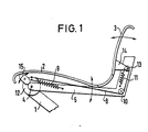
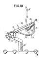
- FIG. 1 shows, in an indicated form, part of a frame 1, which can in principle be implemented in any manner and which carries a seat or a seat surface 2 and a backrest 3.
- Seat 2 and backrest 3 can consist of separate, articulated parts, but also of a one-piece, expandable shell part.
- the seat surface 2 is supported on links 5 or connected to these links 5 extending on both sides of the seat surface, which are pivotable about a horizontal frame axis 4 and are prestressed into a basic position by means of spring force.
- a return spring 9 which serves to reset the seat, is mounted between the frame and an articulation point of the handlebar 5, the handlebar and the spring longitudinal axis forming an acute angle with one another.
- this return spring 9 preferably represents a support spring for the main return spring, which is formed by a torsion bar which is held centrally in a tube forming the horizontal frame axis 4 and is connected at its ends to the links 5 provided on both sides.
- a substantially non-stretchable band 8 is provided, which is attached to the circumference of a frame-fixed disc 12, which is concentric with the horizontal frame axis 4.
- This band 8 runs approximately corresponding to the seat 2 to a mounted on the handlebar 5
- Deflection roller 10 which is located in the region of the transition from the seat 2 to the backrest 3.
- the belt 8 is guided to a shaft 13, which is also rotatably mounted in the angled arm 5, with the circumference or the circumference of a disk fixedly connected to this shaft 13, the belt is firmly connected.
- a support 14 for the backrest 3 is in turn firmly connected to this shaft 13.
- the shaft 13 is prestressed by means of an eirier torsion spring or by means of a tension spring 11 in a direction pulling on the band 8.
- the ratio of seat inclination to backrest inclination can be adjusted in the desired manner by appropriate selection of the articulation points of the band 8.
- backrest 3 can also be pivoted backwards against the force of the tension spring 11, regardless of the backrest inclination predetermined by the seat inclination.
- This separate pivotability of the backrest 3 is also given when different, preferably selectable positions, e.g. can be fixed by means of a pin lock.
- the arrangement for lowering the front edge of the seat surface 2 as a function of the seat surface inclination is of particular importance.
- the front edge of the seat surface 2 is supported by a cam or two-armed lever 15 mounted on the frame, the respective position and thus the height adjustment being dependent on the inclination of the handlebar 5 or the seat surface 2 connected to this handlebar 5.
- the two-armed handlebar 15 is engaged, for example, via a toothing with the end of the handlebar 5, which has the consequence that an inclined position of the handlebar 5 in the sense of a lowering of the rear part of the seat surface 2 for an opposite pivoting of the two-armed lever 15 and thus also leads to a lowering of the front edge of the seat 2.
- This coupled movement gives the user of the seating furniture the impression of a pivot axis of the seating surface located in front of the seating surface and in particular in the area of the hollow of the knees.
- the lowering of the front area of the seat also has a positive effect with regard to a more even distribution of loads in the reclining positions.
- This principle of lowering the front area of the seat can also be implemented independently of the special design of the gear unit in the case of structurally different seating furniture solutions. It is always essential that the elements causing the lowering can be arranged to the side of the seat, so that they take up little space and enable the course of the desired lowering movement to be realized by selecting the appropriate lever ratios.
- the front area of a cantilevered seat surface can have a seat fitting part on which one end of a short intermediate lever is pivoted, which is designed as a two-armed lever and with its other end cooperates with a support arm for the seat surface in such a way that the Support height of the front area of the seat is changed depending on its inclination.
- Fig. 2 shows the embodiment shown in Fig. 1 in a more concrete representation.
- the handlebar 5 supporting the seat surface 2 is angled and roughly follows the contour of the seat surface and backrest.
- the two sections of the angled handlebar 5 form an obtuse angle with one another.
- the longer leg is pivotally connected to the horizontal frame axis in the front seating area.
- a shaft 13 is mounted, with which a support member 14 for the backrest 3 is firmly connected. Rotation of the shaft 13 leads to a corresponding change in the inclination setting of the backrest 3.
- an annular disk 12 is provided fixed to the frame, on the outer circumference of which the band 8 is fastened.
- This band 8 runs within the angled link 5 to a deflecting plate 10 located in the corner region of this link and from there to the shaft 13, to which the band 8 is in turn firmly connected.
- a tension spring 11 is arranged, which is attached at one end to the handlebar 5 and at the other end to the periphery of the shaft 13 so that it wants to cause a pivoting of the shaft 13 counterclockwise and thus also the tape 8.
- This tension spring 11 can also serve as a support spring for a torsion spring provided in the shaft 13 itself.
- a tension spring is also accommodated in the arm of the handlebar 5 which defines the seat inclination, which serves as a return spring and is fixed to the frame above the pivot axis 4 and thus exerts a counterclockwise torque on the handlebar 5.
- This spring can also be a support spring for a torsion bar, which runs according to the joint axis and is connected to the links 5 provided on both sides of the seat.
- the lever 15 used to lower the front area of the seat 2 is in engagement with a lever 5 together with the handlebar 5 pivotable element, and this lever 15 causes a lowering of the support point for the front region of the seat 2 occurs when the lever 5 is pivoted clockwise.
- the extent of the lowering of the front area of the seat can be predetermined in the desired manner by the choice of the translation of the movement.
- Fig. 2 shows the chair in a so-called action-active position, in which the seat 2 extends approximately horizontally and the backrest 3 is pivoted strongly forward.
- the opening angle between the seat and backrest is less than 90 °.
- the backrest 3 can be pivoted independently about the shaft 13 when a corresponding pressure is exerted.
- the gear units arranged on both sides of the seat surface always adapt to the course of the seat surface and backrest and thus the technical functional elements in the concrete design of the armchair largely take a back seat.
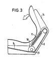
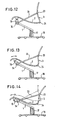
- Fig. 3 shows an advantageous performance detail of the functional seating furniture according to Fig. 2.
- the special feature of this performance variant is that the deflecting member 10 is designed as an eccentric member.
- the non-stretchable band 8 is guided around this eccentric organ.
- the deflecting member 10 has a reduced diameter over a part of its circumference.
- the area of the reduced diameter is preferably designed as a flattened portion 21.
- the deflection element 10 can be rotated by means of a selector lever.
- FIG. 3 shows the seating furniture in a position to be referred to as an action-active position, in which the backrest is pivoted to the front.
- This is achieved in that the deflecting member 10 is pivoted in such a way that the band 8 rests on the flattened part 21 and thus has a smaller distance with respect to the axis of rotation of the deflecting member 10.
- This has the consequence that the backrest can be pivoted forward due to the action of the spring 11 and possibly a torsion spring extending in accordance with the backrest joint.
- a plurality of setting levels can also be provided in order to allow the user to adapt as individually as possible.
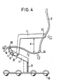
- Fig. 4 shows a functional seating furniture according to the invention with a frame 1 carried by a column 17 with associated roller star 18 for a seat 2 and a backrest 3.
- a first two-armed lever 15 is mounted in its front region on a frame 1 that runs at an obtuse angle with respect to the column 17 via a pivot axis 4.
- This first two-armed lever 15 is connected to the seat surface 2 via a swivel joint 20, specifically in the region of the front end of this seat surface 2.
- the other arm of this first two-armed lever 15 is coupled to an arm of a second two-armed lever 7, in particular via an as Pin-slot connection designed dome axis 6.
- This second two-armed lever 7 is also pivotally mounted on the frame 1, specifically in accordance with the main pivot axis 22, which is preferably designed as a torsion bar spring axis and prestresses the seat surface 2 and backrest 3 into the basic position.
- the second two-armed lever 7 comprises, in addition to the short lever arm already mentioned, which is coupled to the first two-armed lever 15, a comparatively long lever arm which is pivotably articulated on the backrest 3 in a bearing 23.
- This lever arm is preferably designed as an angle lever and runs according to the armrest of the seating furniture.
- the two two-armed levers 7.15 control the kinematics of the seating furniture, the movement possibilities of the seat surface 2 and the backrest 3 are indicated by arrows and the distance between the seat surface and the armrest is indicated by the letter A.
- Fig. 5 shows the seating furniture according to Fig. 4 in the so-called relax position, i.e. in the position in which the seat 2 is lowered the most and the backrest 3 is pivoted to the rear as much as possible.
- the position of the seat, backrest and armrest changed by the kinematics used is possible by comparison with the basic position indicated by dash-dotted lines.
- the seat 2 has been lowered both in the front and in the rear area by the process of leaning back the user of the seating furniture, the extent of the reduction being identified by the number "1".
- the lowering process of the seat surface 2 is triggered by pivoting the second two-armed lever 7 clockwise, the first two-armed lever 15 being pivoted counterclockwise, thereby lowering the front edge of the seat surface 2 on the one hand and, on the other hand, this seat surface 2 being carried forward due to the articulation.
- This forward component in the movement of the seat surface 2 in turn has the result that the opening angle between the seat surface 2 and the backrest 3 is increased due to the rigid connection between the pivot bearings 22 and 23, namely - as indicated by the number "2" - in proportion 1: 2.
- the seat surface 2 When transitioning to the relax position shown in FIG. 11, in the same way as already described in connection with FIG. 8, the seat surface 2 is lowered while the support part 3 'is simultaneously returned to the rear position.
- the movements resulting from the double-lever kinematics advantageously overlap with the movements caused by the band adjusting mechanism in such a way that optimal positions result without actuation of the actuator 31.
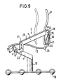
- the frame 12 shows a functional chair designed as a cantilever chair, the seat 2 and backrest 3 of which are carried by a frame 1, the column 17 of which is connected to a roller star 18.
- the frame can be configured in any manner.
- Seat 2 and backrest 3 can be pivoted relative to one another and can be connected to one another via a joint 24.
- the latter is connected in an articulated manner to a lowering lever 15 which is pivotably mounted on an axis fixed to the frame.
- a carrier link 33 which extends between this axis fixed to the frame and the backrest 3, to which it is articulated in a pivot bearing 23, can also be pivoted relative to this axis fixed to the frame.
- This handlebar 33 can also be designed as an armrest at the same time.
- a centrally fixed torsion bar 34 runs coaxially with the axis fixed to the frame, with the ends of which the links 33 provided on both sides of the seat are firmly connected.
- FIG. 13 shows the transition from the starting position shown in FIG. 12 to the position that is approximately half lowered.
- the angle between the seat surface 2 and the backrest 3 is increased and, on the other hand, the seat surface 2 is lowered in the area of its front edge.
- pivoting the handlebar 33 in the clockwise direction results in the pivoting of the lowering lever 15 via an intermediate gear in the counterclockwise direction, thereby moving the seat surface 2 - as indicated by the double arrow - forwards and not only downwards.
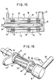
- the axle fixed to the frame is designed as a tube 36 through which the torsion spring 34 extends, which ends are connected in a rotationally fixed manner to a bearing head part 19 which is a component of the link 33.
- a support sleeve 16 is rotatably mounted at a distance from the bearing head part 19, which is fixedly connected to the lowering lever 15, or is formed in one piece.
- blind hole bores 37 which are essentially opposite one another are provided in the basic seating position. These blind holes 37 are each on a circle coaxial to the tube 36.
- an annular disk-shaped deflection element 38 is provided on the tube 36, which is firmly connected to the tube 36 and thus to the frame.
- this deflection member 38 has openings 13, the diameter of which is larger than the diameter of the blind holes.
- the openings 39 are preferably double V-shaped in cross section, so that the rods 40 are guided at the centrally located point of the smallest cross section and can nevertheless carry out the required deflection movements unimpeded.
- the rods 40 which extend through the openings 39 are preferably spring steel rods which engage with their ends in the blind holes 37 of the carrier sleeve 16 and the bearing head part 19. In the basic position of the seating, i.e. When the seat surface is not lowered, the rods 40 preferably rest against the bottom of the blind holes 37, as a result of which a stop or pressure point is obtained.
- the handlebar 33 and lowering handle 15 are pivoted in opposite directions, as shown in FIG. 16, because when the handlebar 33 is pivoted clockwise, the rods 40 are moved through frame-fixed deflector 38 pivot the lowering lever counterclockwise.
- the transmission ratio can be influenced by appropriate positioning of the deflection member 38.
- the axis fixed to the frame is formed by a tube 41, which engages over the support sleeve 16 and the bearing head part 19 and firmly ver with the ring-shaped deflector 38 is bound. In this case there is no connection between the tube 36 and the deflection member 38.
- the tube 36 is used only for rigid coupling of the links 33 provided on both sides of the seat.
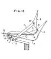
- a preferably multi-armed, for example parallelogram-shaped lever 44 is articulated on a column 17 and is under the pretension of a spring 42 and supports the seat surface 2 via the horizontal frame axis.
- a non-stretchable band 45 is fastened to the periphery of disk or roller members 43.
- the lower disk member 43 is fixed to the frame, while the upper disk member is connected to the torsion spring running along the frame axis.
- Both two-armed levers 7, 15 are designed as angled levers and are connected to one another via a pin-slot coupling.
- the articulation of the first two-armed lever 15 on the seat 2 can take place in the manner shown or directly and directly on the side of the front edge of the seat surface.
- the two arms of each of the two two-armed levers 7, 15 preferably form an angle with one another in the range from 120 ° to 150 °.
- each roller is assigned a circumferential supporting edge 46 (see FIG. 17), with the same circumferential diameter of the chassis. This means that, regardless of the position of the chair castor, a significantly improved safety against tipping can be achieved, and the surrounding support edge can also take on the task of a soft, furniture-protecting bumper.
- the entire chair is preferably designed to be dismantled for dispatch in order to achieve the lowest possible dispatch volume.
- the interfaces lie at the points chassis / column, column / frame handlebar and frame / seat shell, and they are designed so that they can be easily connected and connected in a few simple steps, for which purpose bayonet or screw connections are provided.
- this interface solution enables the construction of chairs according to the modular principle, which can be used to assemble different chairs from different individual elements, which results in a lower capital commitment compared to the storage of completely assembled chairs.
Landscapes
- Health & Medical Sciences (AREA)
- Dentistry (AREA)
- General Health & Medical Sciences (AREA)
- Chairs For Special Purposes, Such As Reclining Chairs (AREA)
- Chairs Characterized By Structure (AREA)
- Pharmaceuticals Containing Other Organic And Inorganic Compounds (AREA)
- Organic Low-Molecular-Weight Compounds And Preparation Thereof (AREA)
- Pyridine Compounds (AREA)
Priority Applications (1)
| Application Number | Priority Date | Filing Date | Title |
|---|---|---|---|
| AT87108041T ATE51501T1 (de) | 1986-06-04 | 1987-06-03 | Funktions-sitzmoebel. |
Applications Claiming Priority (6)
| Application Number | Priority Date | Filing Date | Title |
|---|---|---|---|
| DE3618705A DE3618705C2 (de) | 1986-06-04 | 1986-06-04 | Funktions-Sitzmöbel |
| DE3618705 | 1986-06-04 | ||
| DE3632131 | 1986-09-22 | ||
| DE3632131A DE3632131C2 (de) | 1986-06-04 | 1986-09-22 | Funktions-Sitzmöbel |
| DE3704083 | 1987-02-10 | ||
| DE3704083A DE3704083C2 (de) | 1986-06-04 | 1987-02-10 | Funktions-Sitzmöbel |
Publications (3)
| Publication Number | Publication Date |
|---|---|
| EP0248418A2 EP0248418A2 (de) | 1987-12-09 |
| EP0248418A3 EP0248418A3 (en) | 1988-04-20 |
| EP0248418B1 true EP0248418B1 (de) | 1990-04-04 |
Family
ID=27194458
Family Applications (1)
| Application Number | Title | Priority Date | Filing Date |
|---|---|---|---|
| EP87108041A Expired - Lifetime EP0248418B1 (de) | 1986-06-04 | 1987-06-03 | Funktions-Sitzmöbel |
Country Status (8)
| Country | Link |
|---|---|
| US (1) | US4988145A (es) |
| EP (1) | EP0248418B1 (es) |
| JP (1) | JPH0793898B2 (es) |
| CA (1) | CA1289051C (es) |
| DE (3) | DE3632131C2 (es) |
| DK (1) | DK283387A (es) |
| ES (1) | ES2014010B3 (es) |
| NO (1) | NO872325L (es) |
Families Citing this family (85)
| Publication number | Priority date | Publication date | Assignee | Title |
|---|---|---|---|---|
| DE3800754A1 (de) * | 1987-06-24 | 1989-01-05 | Horst Sondergeld | Sitz fuer einen buerostuhl od. dgl. mit einem insbesondere durch koerpergewichtsverlagerung verstellbaren sitz- und rueckenteil |
| DE3800756A1 (de) * | 1987-06-24 | 1989-01-05 | Horst Sondergeld | Sitz fuer einen buerostuhl od. dgl. |
| DE3844102A1 (de) * | 1988-12-28 | 1990-07-05 | Sondergeld Horst Dipl Designer | Sitz fuer einen buerostuhl od. dgl. |
| FR2627968A1 (fr) * | 1988-03-07 | 1989-09-08 | Eurosit | Siege articule |
| DE3807984A1 (de) * | 1988-03-10 | 1989-09-21 | Roeder Gmbh | Stuhl, insbesondere arbeits- oder buerostuhl |
| DE3817761A1 (de) * | 1988-05-19 | 1989-11-30 | Roeder Gmbh | Stuhl, insbesondere arbeits- oder buerostuhl |
| US5106157A (en) * | 1989-03-01 | 1992-04-21 | Herman Miller, Inc. | Chair height and tilt adjustment mechanisms |
| DE3914832A1 (de) * | 1989-05-05 | 1990-11-08 | Link Wilhelm Kg | Stuhl, insbesondere buerostuhl |
| FR2654683B1 (fr) * | 1989-11-22 | 1992-03-13 | Faure Bertrand Automobile | Perfectionnements aux sieges avant des vehicules automobiles. |
| JP2978244B2 (ja) * | 1989-12-29 | 1999-11-15 | ヴィルカーン ヴィルケニング ウント ハーネゲーエムベーハー ウント コンパニー | 事務椅子のための同期位置調節装置 |
| EP0857443B1 (en) * | 1992-06-15 | 2007-03-07 | Herman Miller, Inc. | Support assembly for a chair |
| US5630643A (en) | 1993-06-01 | 1997-05-20 | Steelcase Inc | Upholstered chair with two-piece shell |
| DE4409098A1 (de) * | 1994-03-17 | 1995-09-21 | Froescher Gmbh & Co Kg | Stuhl mit Neigungsmechanik |
| US5577807A (en) | 1994-06-09 | 1996-11-26 | Steelcase Inc. | Adjustable chair actuator |
| DE4428552C1 (de) * | 1994-08-12 | 1996-02-22 | Simon Desanta | Armlehnenstuhl |
| GB9500022D0 (en) * | 1995-01-04 | 1995-03-01 | Unwalla Jamshed | Integrated seat and back and mechanism for chairs |
| US5573303A (en) * | 1995-05-16 | 1996-11-12 | Doerner Products Ltd. | Chair seat tilting mechanism |
| DE19544545C1 (de) * | 1995-11-29 | 1997-01-16 | Siemens Ag | Vorrichtung zur zwangsgekoppelten Verstellung von Sitz und Rückenlehne eines zahnärztlichen Patientenstuhls |
| FR2749812A1 (fr) * | 1996-06-17 | 1997-12-19 | Faure Bertrand Equipements Sa | Siege avant de vehicule automobile avec appui-tete asservi |
| DE19640564A1 (de) * | 1996-10-01 | 1998-04-02 | Stoll Sedus Ag | Sitzmöbel mit neigbarem Sitz und Rückenlehne |
| US6086153A (en) | 1997-10-24 | 2000-07-11 | Steelcase Inc. | Chair with reclineable back and adjustable energy mechanism |
| DE29903045U1 (de) | 1999-02-19 | 1999-05-06 | Bräutigam, Erhard, 96215 Lichtenfels | Stuhl mit in der Höhe verstellbarem Sitz |
| US6709058B1 (en) | 1999-04-09 | 2004-03-23 | Humanscale Corp. | Ergonomic chair |
| JP4810046B2 (ja) * | 2000-02-29 | 2011-11-09 | タカノ株式会社 | 椅子のロッキング装置 |
| USD448219S1 (en) | 2000-09-28 | 2001-09-25 | Formway Furniture Limited | Castored base for a chair |
| USD463144S1 (en) | 2000-09-28 | 2002-09-24 | Formway Furniture Limited | Chair |
| USD448277S1 (en) | 2000-09-28 | 2001-09-25 | Formway Furniture Limited | Castor |
| USD446397S1 (en) | 2000-09-28 | 2001-08-14 | Formway Furniture Limited | Chair |
| AU783829B2 (en) | 2000-09-28 | 2005-12-08 | Formway Furniture Limited | A reclinable chair |
| USD460300S1 (en) | 2000-09-28 | 2002-07-16 | Formway Furniture Limited | Slotted seat panel for a chair |
| USD445580S1 (en) | 2000-09-28 | 2001-07-31 | Formway Furniture Limited | Chair |
| AUPR054400A0 (en) | 2000-09-29 | 2000-10-26 | Formway Furniture Limited | A castor |
| CN100353889C (zh) * | 2000-10-16 | 2007-12-12 | 科库友株式会社 | 椅子 |
| DE10109624C1 (de) * | 2001-02-28 | 2002-09-12 | Interstuhl Bueromoebel Gmbh | Stuhl, insbesondere Bürostuhl |
| US6644741B2 (en) | 2001-09-20 | 2003-11-11 | Haworth, Inc. | Chair |
| US7396082B2 (en) | 2002-03-29 | 2008-07-08 | Garrex Llc | Task chair |
| US7040703B2 (en) * | 2002-03-29 | 2006-05-09 | Garrex Llc | Health chair a dynamically balanced task chair |
| US7625046B2 (en) * | 2002-03-29 | 2009-12-01 | Garrex Llc | Task chair |
| NZ518944A (en) * | 2002-05-14 | 2004-09-24 | Formway Furniture Ltd | Height adjustable arm for chair with outer stem releasably lockable to inner stem by engagement of recesses |
| JP4137536B2 (ja) * | 2002-07-03 | 2008-08-20 | コクヨ株式会社 | 椅子 |
| US7165811B2 (en) * | 2002-09-12 | 2007-01-23 | Steelcase Development Corporation | Control mechanism for seating unit |
| WO2005006917A2 (en) * | 2003-07-09 | 2005-01-27 | Sanchez Gary L | Task chair |
| US6945602B2 (en) * | 2003-12-18 | 2005-09-20 | Haworth, Inc. | Tilt control mechanism for chair |
| US7172539B1 (en) * | 2004-01-02 | 2007-02-06 | Alice Bythewood | Abdominal exercising support apparatus |
| AU2005244822B2 (en) * | 2004-05-13 | 2012-03-15 | Humanscale Corporation | Mesh chair component |
| USD623449S1 (en) | 2005-05-13 | 2010-09-14 | Humanscale Corporation | Mesh backrest for a chair |
| AR057387A1 (es) | 2005-06-20 | 2007-12-05 | Humanscale Corp | Aparato de asiento con movimiento reclinable |
| CN101495013B (zh) * | 2006-03-24 | 2011-12-14 | 赫尔曼米勒有限公司 | 就座装置 |
| GB0609315D0 (en) * | 2006-05-11 | 2006-06-21 | Technicon Internat Man Service | Improved seat |
| CN101522073A (zh) * | 2006-08-30 | 2009-09-02 | 伊藤喜有限公司 | 椅子 |
| DE202006015734U1 (de) * | 2006-10-13 | 2006-12-14 | Ferdinand Lusch Gmbh & Co. Kg | Liegesessel |
| JP2008136627A (ja) * | 2006-11-30 | 2008-06-19 | Kokuyo Co Ltd | 家具 |
| DE102007001194A1 (de) * | 2007-01-05 | 2008-07-10 | Omp S.R.L | Bewegungsgekoppelte Servoeinrichutng für ein Sitzteil, insbesondere eines Stuhls |
| CN104305754A (zh) | 2007-01-29 | 2015-01-28 | 赫尔曼米勒有限公司 | 座位结构及其使用方法 |
| CA2895942A1 (en) * | 2007-03-13 | 2008-09-13 | Hni Technologies Inc. | Dynamic chair back lumbar support system |
| US7942485B2 (en) * | 2007-05-15 | 2011-05-17 | Kathi Castelluccio | Deployable workstation |
| DE102008011309B3 (de) * | 2008-02-27 | 2009-06-04 | Thonet Gmbh | Bürostuhl |
| JP4379538B1 (ja) * | 2008-10-07 | 2009-12-09 | 沖電気工業株式会社 | 椅子用リンク機構、椅子 |
| CN201602410U (zh) * | 2010-02-04 | 2010-10-13 | 周金坤 | 一种办公休闲两用椅 |
| CN107023096A (zh) | 2010-05-05 | 2017-08-08 | 奥斯蒂尔公司 | 用于对接釉面墙板的可移动且可拆解墙板系统 |
| USD659417S1 (en) | 2010-06-04 | 2012-05-15 | Herman Miller, Inc. | Chair and components thereof |
| US8556345B2 (en) * | 2011-03-14 | 2013-10-15 | Sheng Jia Sheng Co., Ltd. | Chair having angle and tension adjusting functions |
| DE102011001811A1 (de) * | 2011-04-05 | 2012-10-11 | Wilkhahn Wilkening + Hahne Gmbh + Co. Kg | Stuhl |
| US9504326B1 (en) * | 2012-04-10 | 2016-11-29 | Humanscale Corporation | Reclining chair |
| EP2892390B1 (en) * | 2012-09-05 | 2017-06-07 | Godrej & Boyce Mfg Co Ltd | Chair with adjustable backrest and seat |
| US11304528B2 (en) | 2012-09-20 | 2022-04-19 | Steelcase Inc. | Chair assembly with upholstery covering |
| USD697726S1 (en) | 2012-09-20 | 2014-01-21 | Steelcase Inc. | Chair |
| US9706845B2 (en) | 2012-09-20 | 2017-07-18 | Steelcase Inc. | Chair assembly |
| CN105101845B (zh) | 2013-03-15 | 2018-11-09 | Hni技术公司 | 具有触发的靠背弯曲的椅子 |
| US10159350B2 (en) * | 2013-06-07 | 2018-12-25 | Okamura Corporation | Chair |
| DE202014100062U1 (de) * | 2014-01-08 | 2015-04-10 | Innotec Motion GmbH | Sitzmöbel mit federnder Rückenlehne |
| US9801471B2 (en) | 2014-04-17 | 2017-10-31 | Hni Technologies Inc. | Chair and chair control assemblies, systems, and methods |
| USD731833S1 (en) | 2014-04-17 | 2015-06-16 | Allsteel Inc. | Chair |
| WO2015160693A1 (en) | 2014-04-17 | 2015-10-22 | Hni Technologies Inc. | Flex lumbar support |
| USD743180S1 (en) | 2014-10-15 | 2015-11-17 | Hni Technologies Inc. | Chair |
| US9801470B2 (en) | 2014-10-15 | 2017-10-31 | Hni Technologies Inc. | Molded chair with integrated support and method of making same |
| US11259637B2 (en) | 2015-04-13 | 2022-03-01 | Steelcase Inc. | Seating arrangement |
| US10021984B2 (en) | 2015-04-13 | 2018-07-17 | Steelcase Inc. | Seating arrangement |
| US10194750B2 (en) | 2015-04-13 | 2019-02-05 | Steelcase Inc. | Seating arrangement |
| US9713381B2 (en) | 2015-06-11 | 2017-07-25 | Davis Furniture Industries, Inc. | Chair |
| EP4268676A3 (en) | 2019-02-21 | 2024-02-07 | Steelcase Inc. | Body support assembly and methods for the use and assembly thereof |
| WO2020247435A1 (en) * | 2019-06-05 | 2020-12-10 | Davis Furniture Industries, Inc. | Improved tilting chair |
| US11357329B2 (en) | 2019-12-13 | 2022-06-14 | Steelcase Inc. | Body support assembly and methods for the use and assembly thereof |
| US11617444B2 (en) | 2020-03-02 | 2023-04-04 | Steelcase Inc. | Body support assembly and methods for the use and assembly thereof |
| US11812870B2 (en) | 2021-02-10 | 2023-11-14 | Steelcase Inc. | Body support structure |
Family Cites Families (8)
| Publication number | Priority date | Publication date | Assignee | Title |
|---|---|---|---|---|
| GB625800A (en) * | 1942-03-16 | 1949-07-04 | Anion Lorenz | Improved adjustable chairs |
| US2509739A (en) * | 1944-11-17 | 1950-05-30 | Push Back Chair Co | Theater chair |
| US2492106A (en) * | 1946-06-29 | 1949-12-20 | American Seating Co | Retracting type theater chair |
| US2492103A (en) * | 1946-06-29 | 1949-12-20 | American Seating Co | Retracting type theater chair |
| US2796918A (en) * | 1954-09-15 | 1957-06-25 | Norman P Martin | Article of repose for supporting the body of a person |
| US3139305A (en) * | 1962-05-09 | 1964-06-30 | Gen Steel Products Inc | Reclining chair and fixture |
| CH645795A5 (en) * | 1979-07-23 | 1984-10-31 | Drabert Soehne | Chair, in particular visual display unit chair |
| DE3313677C2 (de) * | 1983-04-15 | 1986-08-14 | Burkhard 7842 Kandern Vogtherr | Sitzmöbel, insbesondere Bürostuhl mit synchron verstellbarer Rückenlehne und Sitzfläche |
-
1986
- 1986-09-22 DE DE3632131A patent/DE3632131C2/de not_active Expired - Fee Related
-
1987
- 1987-02-10 DE DE3704083A patent/DE3704083C2/de not_active Expired - Fee Related
- 1987-06-03 DE DE8787108041T patent/DE3762082D1/de not_active Expired - Lifetime
- 1987-06-03 ES ES87108041T patent/ES2014010B3/es not_active Expired - Lifetime
- 1987-06-03 NO NO872325A patent/NO872325L/no unknown
- 1987-06-03 DK DK283387A patent/DK283387A/da not_active Application Discontinuation
- 1987-06-03 EP EP87108041A patent/EP0248418B1/de not_active Expired - Lifetime
- 1987-06-04 CA CA000538855A patent/CA1289051C/en not_active Expired - Lifetime
- 1987-06-04 JP JP62140712A patent/JPH0793898B2/ja not_active Expired - Lifetime
-
1989
- 1989-06-06 US US07/363,346 patent/US4988145A/en not_active Expired - Fee Related
Also Published As
| Publication number | Publication date |
|---|---|
| DE3704083A1 (de) | 1988-08-18 |
| ES2014010B3 (es) | 1990-06-16 |
| DK283387D0 (da) | 1987-06-03 |
| DE3704083C2 (de) | 2002-09-05 |
| DK283387A (da) | 1987-12-05 |
| DE3632131C2 (de) | 2001-12-13 |
| CA1289051C (en) | 1991-09-17 |
| JPS63109818A (ja) | 1988-05-14 |
| NO872325L (no) | 1987-12-07 |
| NO872325D0 (no) | 1987-06-03 |
| JPH0793898B2 (ja) | 1995-10-11 |
| US4988145A (en) | 1991-01-29 |
| DE3632131A1 (de) | 1988-03-31 |
| EP0248418A2 (de) | 1987-12-09 |
| EP0248418A3 (en) | 1988-04-20 |
| DE3762082D1 (de) | 1990-05-10 |
Similar Documents
| Publication | Publication Date | Title |
|---|---|---|
| EP0248418B1 (de) | Funktions-Sitzmöbel | |
| DE4220881C2 (de) | Stoßdämpfer für die Rückenlehne von Sitzen | |
| EP1454566B1 (de) | Stuhl, insbesondere Bürostuhl | |
| EP0638265B1 (de) | Bürostuhl | |
| DE10026292C2 (de) | Stuhl | |
| DE69215966T2 (de) | Kontrollmechanismus für Stühle | |
| EP1592324B1 (de) | Verstellbares sitzmöbel | |
| DE19945118A1 (de) | Sessel mit Aufstehhilfe | |
| EP3120732B1 (de) | Mechanik für einen bürostuhl | |
| DE60221793T2 (de) | Stühle | |
| EP1708595A2 (de) | Möbelantrieb zum verstellen eines ersten teiles eines möbels relativ zu einem zweiten teil | |
| EP1209994B1 (de) | Stuhl | |
| DE10126000A1 (de) | Synchronmechanik für die simultane Sitzflächen- und Rückenlehnen-Schwenkbewegung bei Bürostühlen | |
| DE102007021782B3 (de) | Synchronmechanik für Bürostühle | |
| DE3618705C2 (de) | Funktions-Sitzmöbel | |
| EP0341344B1 (de) | Sitzmöbel | |
| DE19931099C2 (de) | Stuhl mit selbständiger Anpassung der Vorbelastungskraft der Rückenlehne | |
| EP1874160A1 (de) | Sitzmöbel, insbesondere bürostuhl | |
| DE102004050853A1 (de) | Stuhl | |
| EP4129117B1 (de) | Sitzmöbel | |
| EP1346664A2 (de) | Vorrichtung zum Verstellen der Nackenstütze eines Sitzmöbels | |
| DE3619928A1 (de) | Funktions-sitzmoebel | |
| DE3914832A1 (de) | Stuhl, insbesondere buerostuhl | |
| DE1936934A1 (de) | Verstellbarer Stuhl mit verstellbarer Kopfstuetze | |
| DE29615997U1 (de) | Stuhl, insbesondere Bürodrehstuhl |
Legal Events
| Date | Code | Title | Description |
|---|---|---|---|
| PUAI | Public reference made under article 153(3) epc to a published international application that has entered the european phase |
Free format text: ORIGINAL CODE: 0009012 |
|
| AK | Designated contracting states |
Kind code of ref document: A2 Designated state(s): AT BE CH DE ES FR GB IT LI NL SE |
|
| RAP1 | Party data changed (applicant data changed or rights of an application transferred) |
Owner name: ENGEL, HARTMUT S. Owner name: ROEDER GMBH SITZMOEBELWERKE |
|
| PUAL | Search report despatched |
Free format text: ORIGINAL CODE: 0009013 |
|
| AK | Designated contracting states |
Kind code of ref document: A3 Designated state(s): AT BE CH DE ES FR GB IT LI NL SE |
|
| 17P | Request for examination filed |
Effective date: 19880603 |
|
| 17Q | First examination report despatched |
Effective date: 19890821 |
|
| GRAA | (expected) grant |
Free format text: ORIGINAL CODE: 0009210 |
|
| AK | Designated contracting states |
Kind code of ref document: B1 Designated state(s): AT BE CH DE ES FR GB IT LI NL SE |
|
| REF | Corresponds to: |
Ref document number: 51501 Country of ref document: AT Date of ref document: 19900415 Kind code of ref document: T |
|
| ITF | It: translation for a ep patent filed | ||
| REF | Corresponds to: |
Ref document number: 3762082 Country of ref document: DE Date of ref document: 19900510 |
|
| ET | Fr: translation filed | ||
| GBT | Gb: translation of ep patent filed (gb section 77(6)(a)/1977) | ||
| PLBE | No opposition filed within time limit |
Free format text: ORIGINAL CODE: 0009261 |
|
| STAA | Information on the status of an ep patent application or granted ep patent |
Free format text: STATUS: NO OPPOSITION FILED WITHIN TIME LIMIT |
|
| 26N | No opposition filed | ||
| ITTA | It: last paid annual fee | ||
| EAL | Se: european patent in force in sweden |
Ref document number: 87108041.2 |
|
| PGFP | Annual fee paid to national office [announced via postgrant information from national office to epo] |
Ref country code: GB Payment date: 20010521 Year of fee payment: 15 |
|
| PGFP | Annual fee paid to national office [announced via postgrant information from national office to epo] |
Ref country code: FR Payment date: 20010618 Year of fee payment: 15 |
|
| PGFP | Annual fee paid to national office [announced via postgrant information from national office to epo] |
Ref country code: CH Payment date: 20010622 Year of fee payment: 15 Ref country code: AT Payment date: 20010622 Year of fee payment: 15 |
|
| PGFP | Annual fee paid to national office [announced via postgrant information from national office to epo] |
Ref country code: SE Payment date: 20010625 Year of fee payment: 15 Ref country code: BE Payment date: 20010625 Year of fee payment: 15 |
|
| PGFP | Annual fee paid to national office [announced via postgrant information from national office to epo] |
Ref country code: NL Payment date: 20010626 Year of fee payment: 15 |
|
| PGFP | Annual fee paid to national office [announced via postgrant information from national office to epo] |
Ref country code: ES Payment date: 20010709 Year of fee payment: 15 |
|
| PGFP | Annual fee paid to national office [announced via postgrant information from national office to epo] |
Ref country code: DE Payment date: 20010713 Year of fee payment: 15 |
|
| REG | Reference to a national code |
Ref country code: GB Ref legal event code: IF02 |
|
| PG25 | Lapsed in a contracting state [announced via postgrant information from national office to epo] |
Ref country code: GB Free format text: LAPSE BECAUSE OF NON-PAYMENT OF DUE FEES Effective date: 20020603 Ref country code: AT Free format text: LAPSE BECAUSE OF NON-PAYMENT OF DUE FEES Effective date: 20020603 |
|
| PG25 | Lapsed in a contracting state [announced via postgrant information from national office to epo] |
Ref country code: SE Free format text: LAPSE BECAUSE OF NON-PAYMENT OF DUE FEES Effective date: 20020604 Ref country code: ES Free format text: LAPSE BECAUSE OF NON-PAYMENT OF DUE FEES Effective date: 20020604 |
|
| PG25 | Lapsed in a contracting state [announced via postgrant information from national office to epo] |
Ref country code: LI Free format text: LAPSE BECAUSE OF NON-PAYMENT OF DUE FEES Effective date: 20020630 Ref country code: CH Free format text: LAPSE BECAUSE OF NON-PAYMENT OF DUE FEES Effective date: 20020630 Ref country code: BE Free format text: LAPSE BECAUSE OF NON-PAYMENT OF DUE FEES Effective date: 20020630 |
|
| BERE | Be: lapsed |
Owner name: *ENGEL HARTMUT S. Effective date: 20020630 Owner name: *RODER G.M.B.H. SITZMOBELWERKE Effective date: 20020630 |
|
| PG25 | Lapsed in a contracting state [announced via postgrant information from national office to epo] |
Ref country code: NL Free format text: LAPSE BECAUSE OF NON-PAYMENT OF DUE FEES Effective date: 20030101 Ref country code: DE Free format text: LAPSE BECAUSE OF NON-PAYMENT OF DUE FEES Effective date: 20030101 |
|
| GBPC | Gb: european patent ceased through non-payment of renewal fee |
Effective date: 20020603 |
|
| EUG | Se: european patent has lapsed | ||
| REG | Reference to a national code |
Ref country code: CH Ref legal event code: PL |
|
| PG25 | Lapsed in a contracting state [announced via postgrant information from national office to epo] |
Ref country code: FR Free format text: LAPSE BECAUSE OF NON-PAYMENT OF DUE FEES Effective date: 20030228 |
|
| NLV4 | Nl: lapsed or anulled due to non-payment of the annual fee |
Effective date: 20030101 |
|
| REG | Reference to a national code |
Ref country code: FR Ref legal event code: ST |
|
| REG | Reference to a national code |
Ref country code: ES Ref legal event code: FD2A Effective date: 20030711 |
|
| PG25 | Lapsed in a contracting state [announced via postgrant information from national office to epo] |
Ref country code: IT Free format text: LAPSE BECAUSE OF NON-PAYMENT OF DUE FEES;WARNING: LAPSES OF ITALIAN PATENTS WITH EFFECTIVE DATE BEFORE 2007 MAY HAVE OCCURRED AT ANY TIME BEFORE 2007. THE CORRECT EFFECTIVE DATE MAY BE DIFFERENT FROM THE ONE RECORDED. Effective date: 20050603 |