US6644741B2 - Chair - Google Patents
Chair Download PDFInfo
- Publication number
- US6644741B2 US6644741B2 US09/957,695 US95769501A US6644741B2 US 6644741 B2 US6644741 B2 US 6644741B2 US 95769501 A US95769501 A US 95769501A US 6644741 B2 US6644741 B2 US 6644741B2
- Authority
- US
- United States
- Prior art keywords
- seat
- axis
- seat member
- chair
- upright
- Prior art date
- Legal status (The legal status is an assumption and is not a legal conclusion. Google has not performed a legal analysis and makes no representation as to the accuracy of the status listed.)
- Expired - Lifetime
Links
Images


Classifications
-
- A—HUMAN NECESSITIES
- A47—FURNITURE; DOMESTIC ARTICLES OR APPLIANCES; COFFEE MILLS; SPICE MILLS; SUCTION CLEANERS IN GENERAL
- A47C—CHAIRS; SOFAS; BEDS
- A47C1/00—Chairs adapted for special purposes
- A47C1/02—Reclining or easy chairs
- A47C1/031—Reclining or easy chairs having coupled concurrently adjustable supporting parts
- A47C1/032—Reclining or easy chairs having coupled concurrently adjustable supporting parts the parts being movably-coupled seat and back-rest
- A47C1/03255—Reclining or easy chairs having coupled concurrently adjustable supporting parts the parts being movably-coupled seat and back-rest with a central column, e.g. rocking office chairs
-
- A—HUMAN NECESSITIES
- A47—FURNITURE; DOMESTIC ARTICLES OR APPLIANCES; COFFEE MILLS; SPICE MILLS; SUCTION CLEANERS IN GENERAL
- A47C—CHAIRS; SOFAS; BEDS
- A47C1/00—Chairs adapted for special purposes
- A47C1/02—Reclining or easy chairs
- A47C1/031—Reclining or easy chairs having coupled concurrently adjustable supporting parts
- A47C1/032—Reclining or easy chairs having coupled concurrently adjustable supporting parts the parts being movably-coupled seat and back-rest
- A47C1/03261—Reclining or easy chairs having coupled concurrently adjustable supporting parts the parts being movably-coupled seat and back-rest characterised by elastic means
- A47C1/03266—Reclining or easy chairs having coupled concurrently adjustable supporting parts the parts being movably-coupled seat and back-rest characterised by elastic means with adjustable elasticity
-
- A—HUMAN NECESSITIES
- A47—FURNITURE; DOMESTIC ARTICLES OR APPLIANCES; COFFEE MILLS; SPICE MILLS; SUCTION CLEANERS IN GENERAL
- A47C—CHAIRS; SOFAS; BEDS
- A47C1/00—Chairs adapted for special purposes
- A47C1/02—Reclining or easy chairs
- A47C1/031—Reclining or easy chairs having coupled concurrently adjustable supporting parts
- A47C1/032—Reclining or easy chairs having coupled concurrently adjustable supporting parts the parts being movably-coupled seat and back-rest
- A47C1/03261—Reclining or easy chairs having coupled concurrently adjustable supporting parts the parts being movably-coupled seat and back-rest characterised by elastic means
- A47C1/03272—Reclining or easy chairs having coupled concurrently adjustable supporting parts the parts being movably-coupled seat and back-rest characterised by elastic means with coil springs
-
- A—HUMAN NECESSITIES
- A47—FURNITURE; DOMESTIC ARTICLES OR APPLIANCES; COFFEE MILLS; SPICE MILLS; SUCTION CLEANERS IN GENERAL
- A47C—CHAIRS; SOFAS; BEDS
- A47C1/00—Chairs adapted for special purposes
- A47C1/02—Reclining or easy chairs
- A47C1/031—Reclining or easy chairs having coupled concurrently adjustable supporting parts
- A47C1/032—Reclining or easy chairs having coupled concurrently adjustable supporting parts the parts being movably-coupled seat and back-rest
- A47C1/03294—Reclining or easy chairs having coupled concurrently adjustable supporting parts the parts being movably-coupled seat and back-rest slidingly movable in the base frame, e.g. by rollers
Definitions
- This invention relates to an office-type chair, and more specifically relates to an improved synchrotilt mechanism coupled to the seat and back of the chair for providing improved seating comfort.
- Office chairs conventionally provide some type of rearward tilting movement.
- the rear tilting involves solely the back, or the seat and back as a unitary construction.
- many office-type chairs employ a synchrotilt mechanism coupled between the chair base and the seat-back assembly, for permitting the seat and back to simultaneously tilt at different rates, with the tilt rate and maximum tilt angle of the back typically being about twice the tilt rate and maximum tilt angle of the seat.
- This hip axis is disposed in upwardly spaced relation from the rear portion of the seat, and spaced forwardly from the lower portion of the chair back. While locating the relative tilt axis between the seat and back at the occupant's hip axis is believed to provide improved performance, particularly with respect to minimizing the relative sliding motion between the seated occupant and the seat/back, nevertheless many of these known mechanisms still fail to provide the degree of performance desired, particularly with respect to the desired comfort and ease of movement (often referred to as “ride”) associated with tilting of the chair.
- the chair back is supported on a rigid upright assembly which includes lower lever arms which project under the chair seat and are coupled at forward ends thereof to a horizontal tilt shaft which is disposed under the front of the chair seat and is supported on a control housing fixed to the upper end of the base pedestal.
- a conventional tension control mechanism is disposed in the control housing and coupled between the tilt shaft and the control housing for normally urging the upright arrangement, and the chair back, into an upright position.
- the chair seat is movably supported on the lower lever arms of the upright assembly by a support arrangement which permits the chair seat to pivot relative to the upright assembly about a generally transverse horizontal axis which is preferably slightly below the upper surface of the seat when the latter is in a nondeformed condition, i.e., the seat is not occupied.
- a tilt control mechanism is coupled between the control housing, the upright assembly and the seat frame so as to permit synchronized tilting of the seat relative to the back in response to tilting of the back about the axis of the tilt shaft.
- rearward tilting of the chair back, and relative but synchronized tilting of the chair seat as controlled by the tilt control linkage which is coupled between the chair back and seat and the stationary control housing, as well as the tilt support mechanism which couples the seat to the upright assembly, enables the body of the chair occupant to more naturally flex at various joints so as to provide for improved user comfort when the chair is occupied. More specifically, during the rearward and synchronized tilting of the seat and back, both the seat and back remain in proper supportive engagement with the occupant's body so as to effectively eliminate or at least greatly minimize any relative sliding between the occupant's body and either the back or seat.
- the occupant's body undergoes natural flexing and opening of the angle at the ankle joint, the knee joint and the hip joint as the chair is tilted rearwardly, while enabling the occupant's feet to remain comfortably and stably supported on the floor throughout the range of rearward tilt movement, thereby providing an improved degree of comfort to the seated occupant which is believed at least equivalent to mechanisms which provide so-called “knee tilt” or “ankle tilt” motion.
- the tiltable support of the seat on the upright assembly is configured so that tilting of the seat relative to the upright occurs about an axis which is disposed below the normal nondeformed upper surface of the seat, whereby this axis hence is disposed approximately at the contact zone between the hip bone and the seat when the seat is occupied and deformed, thereby permitting a more natural rolling contact between the hip bone and the seat so as to eliminate or at least greatly minimize any relative sliding at the contact zone.
- FIG. 1 is a perspective view of an office-type chair employing the improved tilt control mechanism of the present invention.
- FIG. 2 is a perspective view showing the upright assembly having the seat cradle mounted thereon, and showing the connection to the chair control housing according to the present invention.
- FIG. 3 is a side elevational view of the assembly shown in FIG. 2 .
- FIG. 4 is a top view of the assembly shown in FIG. 3 .
- FIG. 5 is a front view of the assembly shown in FIG. 3 .
- FIG. 6 is a side elevational view similar to FIG. 3 but showing various parts in a separated position for clarity of illustration.
- FIGS. 7A and 7B are enlarged side elevational views which respectively diagrammatically depict the relationships of the chair seat and back when in both the normal upright position and the maximum rearward tilt position.
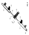
- FIG. 8 is a perspective view, in a partially disassembled condition, of the main tilt shaft for the chair and its connection to a biasing unit.
- FIG. 9 is a perspective view of the assembled tilt shaft arrangement of FIG. 8 .
- FIG. 10 is a perspective view illustrating a resilient support which couples between the base and the synchrotilt control linkage for permitting limited forward tilt of the chair seat independent of the rear tilt linkage.
- the chair 11 includes a base 12 provided with a plurality of legs 14 which radiate outwardly and are provided with casters for rolling support on a floor.
- the base 12 centrally thereof, has a height-adjustable pedestal 13 which projects upwardly and, at the upper end thereof, couples to a chair control 16 , the latter in turn providing support for an L-shaped seat-back arrangement 17 which includes a seat assembly 18 and a back assembly 19 .
- the seat assembly 18 includes a rigid seat frame or cradle 21 defined by a generally rectangular ring-shaped top frame 22 which, adjacent opposite sides, is provided with generally parallel side frame elements 23 .
- the elements 23 are generally U-shaped and protrude downwardly, with upper ends of the legs being rigidly joined adjacent the front and rear corners of the top frame 22 .
- the seat assembly 18 also includes a thin sheetlike seat shell 24 stationarily positioned on the upper surface of the top frame 22 , and a compressible seat cushion 25 supported on and extending generally coextensively over the upper surface of the seat shell 24 .
- the cushion 25 terminates in respective front and rear edges 26 and 27 , the latter being defined in close proximity to the back assembly 19 .
- the seat cushion defines thereon an upper surface 28 disposed for contacting engagement with a chair occupant.
- the seat cushion 25 when engaged with a seated occupant, resiliently deforms downwardly so that the upper surface 28 , at least in the main central region of the cushion where engaged with the occupant, is deflected downwardly from the nondeformed position indicated in FIGS. 6 and 7.
- the back assembly 19 is supported on a generally rigid upright structure 31 which is defined by a pair of generally parallel and sidewardly positioned L-shaped side upright elements or members 32 , each of which has a lower lever arm portion 33 positioned below the seat shell 24 and which, at a rearward end, is joined through an integral bend to an upper arm portion 34 which is cantilevered upwardly and has the back assembly 19 mounted thereon.
- the sidewardly spaced uprights 32 are, adjacent the lower ends of the upper arm portions 34 , rigidly joined by a cross member 35 extending therebetween.
- the forward ends of the lower lever arm portions 33 are nonrotatably connected to a tilt shaft 42 which defines a rotational axis 43 extending generally horizontally in transverse relationship relative to the seat assembly 18 .
- the tilt shaft 42 is rotatably supported within a housing or support arm 41 which is fixed to the upper end of the height-adjusting pedestal 13 , with the housing 41 being cantilevered forwardly from the pedestal so that the tilt shaft 42 is positioned under but more closely adjacent the front edge 26 of the seat cushion 25 .
- the tilt shaft 42 projects outwardly through openings 44 formed in opposite sides of the housing 41 so that opposite end portions of the tilt shaft 42 are disposed on opposite sides of the housing 41 .
- the projecting end portions of the shaft 42 in turn project through openings 45 associated with the forward ends of the lower lever arm portions 33 , with these latter arm portions being keyed or otherwise suitably nonrotatably secured to the shaft 42 , whereby the rigid upright arrangement 31 is angularly movable about the horizontal axis 43 in correspondence with angular displacement of the tilt shaft 42 .
- the housing 41 functions as an enclosure for a conventional biasing or spring mechanism for normally urging the back assembly 19 into an upright position.
- the chair employs a biasing or spring mechanism 81 which is disposed within the interior of the control housing 41 and includes a spring 82 , namely an elongate bar-like torsion spring in the illustrated embodiment.
- This torsion spring 82 has an arm 83 anchored thereto substantially at the center of the spring, which arm at its other end is stationarily interconnected to the control housing 41 , typically through a manually-adjustable tensioning mechanism which permits limited swinging of the arm so as to adjust the initial torsion of the torsion spring 82 .
- This torsion spring 82 as it projects outwardly from opposite sides of the mounting arm 83 , is telescoped within the interior of coaxially aligned shaft segments which define the main tilt shaft 42 , and the free ends of the torsion spring 82 are nonrotatably secured to the shaft segments defining the shaft 42 .
- the shaft segments also have stop members 84 fixed thereto and cooperating with opposed stops (not shown) associated with the control housing 41 for defining the permissible angle of movement of the shaft 42 and of the back arrangement as coupled thereto through the upright structure. While the biasing mechanism 81 as described above represents one arrangement for effecting biasing of the chair into its normal upright position, it will be recognized that numerous other biasing mechanisms employing other types of spring devices are well known and hence could be usable with the chair of the present invention.
- a control linkage 51 is operatively coupled between the base and the seat frame or cradle 21 , and is additionally coupled to the upright arrangement 31 , as explained below.
- the tilt control linkage 51 includes two substantially identical linkages which are effectively mirror images of one another and are disposed on opposite sides of the chair control housing 41 for cooperation with the respective lower upright arms 33 and cradle side frame elements 23 as associated with the same side of the chair, as described below. Only one of the linkages 51 is described, it being understood that both linkages cooperate and function simultaneously in the same manner as described.
- control linkage 51 permits synchronized but relative tilting of the seat and back with respect to the base, and for this purpose includes a main control link or lever 52 which is elongated in the front-to-rear direction of the chair and which, at a forward end thereof, has a transverse pivot shaft 53 which is rotatably supported with an opening 54 associated with one side of the control housing 41 so as to define a transverse horizontal hinge axis 55 .
- the hinge axis 55 is generally parallel with but spaced rearwardly and downwardly from the main tilt axis 43 .
- the other or rearward end of the main control lever 52 also has a transversely projecting pivot shaft end 56 mounting thereon a roller 57 rotatable about a transverse horizontal axis 58 which is generally parallel with but spaced rearwardly from the hinge axis 55 .
- the roller 57 is confined for movement within an elongate slot 59 as formed in the inner side wall of the adjacent lower lever arm portion 33 of the upright side member 32 .
- the slot 59 is elongated in the front-to-rear direction of the chair seat, and in the front-to-rear direction of the lower arm portion 33 , with the longitudinal direction of the slot extending at a significant acute angle relative to the lengthwise direction of the main control lever 52 as defined transversely between the hinge axes 55 and 58 .
- transverse shaft end 56 associated with the rearward end of control lever 52 passes through an enlarged clearance hole 61 formed in the side element 23 of the seat cradle so as to permit access to the control slot 59 formed in the adjacent lever arm portion 33 .
- the control linkage 51 also includes a secondary control link or lever 62 which is also elongated in the front-to-rear direction of the chair seat.
- the secondary control lever 62 has openings 63 and 64 extending sidewardly (i.e. horizontally) therethrough adjacent the respective forward and rearward ends thereof.
- a horizontally oriented coupling pin 65 has one end thereof mounted in the front opening 63 , and the other end thereof is engaged within a suitable opening 67 formed in the side of the seat cradle 21 , whereby coupling pin 65 defines a transverse horizontal pivot axis 66 which is parallel with the main tilt axis 43 .
- the opening 67 formed in the seat cradle 21 is positioned within the lower or base leg of the generally U-shaped side frame element 23 , and is positioned more closely adjacent the forward end of this base leg.
- the opening 64 as associated with the rearward end of the secondary control lever 62 is pivotally engaged around the rear transverse pivot shaft 56 associated with the main control lever 52 so that secondary lever 62 and main lever 52 are coupled together for relative pivoting movement about the axis 58 .
- the synchronized but differential tilting of the seat and back with respect to the base is further controlled by a pivotal support mechanism 71 which couples the seat cradle 21 to the upright arrangement 31 .
- the pivotal support mechanism 71 includes a pair of aligned front rollers 72 which are mounted on opposite sides of the seat cradle 21 and project outwardly from the outer side surfaces of the side frame elements 23 in the vicinity of the front ends thereof.
- the aligned front rollers 72 define a pivot or rotational axis 73 which extends transversely in horizontal orientation so as to be generally parallel with the tilt axis 43 .
- a further pair of rearward rollers 74 are similarly mounted on the outer sides of the cradle side frame elements 23 and are disposed in aligned relationship so as to be rotatable about a transverse horizontal axis 75 which is generally parallel with but spaced rearwardly a substantial distance from the front roller axis 73 .
- the rear rollers 74 are positioned adjacent the rearward ends of the cradle side frame elements 23 .
- the pivotal support mechanism 71 also includes a pair of elongate front slots 76 and a further pair of elongate rear slots 77 which are formed in the lower lever arms 33 for individually movably accommodating therein a respective said front or rear roller 72 or 74 . More specifically, the pair of front slots 76 open inwardly in opposed relationship to one another from the inner side surface of the lower lever arms 33 , and in similar fashion the pair of rear slots 77 are disposed in opposed relationship to one another and open inwardly into the respective lower lever arms 33 from the inner side surface thereof.
- the front slots 76 are positioned between the tilt shaft 42 and the elongate slots 59 in the front-to-rear direction of the chair seat, and the rear slots 77 are positioned rearwardly of the slots 59 but somewhat forwardly from the upper upright arms 34 .
- the front slots 76 and the rear slots 77 are both of an upwardly-facing arcuate configuration in that they are each generated on a uniform radius generated about a common center point or axis 78 which, as illustrated in FIG. 6, is positioned at an elevation whereby this center point or axis 78 is preferably a small distance below the upper surface 28 of the seat cushion 23 when the seat cushion is not deformed, i.e., the seat is not occupied.
- the center point or axis 78 is disposed more closely adjacent the rear edge 27 of the seat cushion but is spaced forwardly therefrom so as to be, when viewed horizontally, spaced forwardly a small distance from the back 36 .
- the center point or axis 78 is preferably oriented so as to be generally aligned with but spaced vertically downwardly from the hip point or hip axis 79 associated with the hips of the chair occupant, which hip axis 79 is always spaced upwardly a small distance above the chair seat and is always spaced forwardly a small distance (i.e., several inches) from the chair back.
- the center point or axis 78 used for generating the curvature of the slots 76 and 77 is typically spaced downwardly a small distance below the upper surface 28 of the nondeformed seat cushion 23 such that, when the seat cushion 23 and the upper surface 28 thereof are deformed downwardly due to an occupant seated thereon, the upper surface 28 of the seat cushion at least in the center portion thereof directly under the occupant's hips is deformed downwardly so that the generating axis 78 for the slots 76 - 77 is preferably disposed at and more preferably slightly above the upper surface 28 of the occupant-deformed cushion 25 , whereby the axis 78 will more closely be positioned for substantially tangential contact with the outer periphery of the occupant's hip bones. With this relationship, the occupant's hips where they contact the deformed chair seat thus remain stationary during synchronized rearward tilting of the seat and back with respect to the chair base.
- the center point or axis 78 will typically be in the range of about one-half to about one inch below the upper surface 28 of the seat cushion 25 when the latter is unoccupied and hence not compressed or externally deformed.
- the seat-back arrangement 17 When the chair is in an unoccupied condition, the seat-back arrangement 17 will be maintained in its generally upright or forward position due to the resilient urging of the spring or biasing mechanism 81 associated with the control assembly, which biasing mechanism always urges the seat-back assembly in a vertical direction about the tilt axis 43 (counterclockwise in FIGS. 6 and 7) into engagement with a suitable stop which defines the upright position.
- the occupant may elect to tilt rearwardly by applying suitable backward pressure against the chair back, causing the back assembly to tilt rearwardly (clockwise in FIGS. 6 and 7) about the tilt axis 43 against the urging of the biasing or spring device 81 .
- the rearward tilting of the upright arrangement 31 about tilt axis 43 causes the lower upright arms 33 to vertically swing downwardly about axis 43 .
- This movement causes the main control lever 52 to also swing downwardly, and simultaneously causes the roller 57 as engaged in the slot 59 to move rearwardly along the slot 59 as defined in the lower upright arm 33 .
- the downward swinging of upright lower arm 33 also causes the seat cradle 21 to be swung downwardly therewith due to the engagement of the rollers 72 and 74 within the respective slots 76 and 77 . This connection tends to tilt the seat cradle downwardly at the same rate as the back upright arrangement.
- This relative rotation of the seat cradle 21 is in the opposite rotational direction to that of the lower upright arms 33 , although at a lesser rate, so that the overall net effect is that the seat cradle 21 also effectively tilts rearwardly simultaneous with the rearward tilting of the lever arms 33 , except that the rearward tilting of the seat cradle occurs at a significantly lesser rate of movement.
- the tilting of the seat cradle 21 relative to the back assembly occurs about the axis 78 which is approximately vertically aligned with but spaced downwardly below the occupant's hip axis 79 , with the center of relative tilting movement 78 being positioned adjacent and typically slightly above the deformed upper surface 28 of the seat cushion so that this tilt axis 78 is positioned to approximately transversely intersect the rounded exterior profile of the occupant's hip bones whereby, during the rearward flexing of the occupant's upper body portion about the hips relative to the lower body portion, the movement of the body closely conforms with the simultaneous but relative tilting movements of the back and seat so as to permit comfortable disposition of the occupant on the seat without undergoing significant relative sliding at the contact areas.
- the rearward tilting permits the occupant's knees to readily flex in an opening direction while the occupant's feet remain properly and comfortably engaged with the floor with overall rearward tilting of the occupant being permitted due to rearward flexing of the occupant's legs about the ankles.
- the control linkage 51 of the present invention also includes a resilient support 91 (FIG. 10) which is associated with the forward shaft end 53 of the main control lever 52 for permitting the seat cradle 21 to rock or rotate through a small angle about the axis 78 in a direction which permits the front edge 26 of the seat cushion to be depressed, even though the upright structure 31 is maintained stationary.
- a resilient support 91 FIG. 10
- the opening 54 formed in the control housing 41 is formed as a slot which is elongated generally in the elongate direction of the main control lever 52 .
- the forward shaft ends 53 associated with the main control levers 52 project through the elongate openings or slots 54 formed in opposite sides of the hollow control housing 41 , which slots 54 and their cooperation with the shaft ends 53 define lost-motion connections.
- These forward shaft ends 53 are in turn rotatably engaged within support sleeves or bearings 93 mounted within opposite ends of a horizontally elongate support shaft 92 which is positioned interiorly of the hollow control housing 41 and extends transversely of the chair.
- the support shaft 92 cooperates with a pair of biasing springs 94 which have one ends thereof transversely bearing against the shaft, and the other ends anchored with respect to mounting brackets 95 which are fixedly secured with respect to the control housing 41 .
- Guide rods 96 are fixed to the brackets 95 and project through the interior of the springs 94 , with the other ends of the guide rods being transversely slidably supported on the support shaft 92 .
- the springs 94 acting against the support shaft 92 urge the support shaft transversely such that the forward hinge shafts 53 , as engaged with opposite ends of the support shaft 92 , are normally maintained in engagement with the forward ends of the elongate slots 54 formed in the control housing side walls.
- the forward shaft ends 53 are normally resiliently maintained in engagement with the forward ends of the housing slots 54 , and rearward tilting of the chair as described above will occur in a normal manner, during which the forward shaft ends 53 associated with the control linkage 51 remain positioned in abutting engagement with the forward end walls of the slots 54 .
- the seat cradle 21 rotates about the axis 78 in a direction whereby the rollers 72 and 74 move rearwardly of their respective slots (counterclockwise in FIG.
- the seat cradle 21 can be controlled by the occupant so as to tilt forwardly through a small angular extent and hence effect a slight downward movement or lowering of the front edge of the seat.
- Such tilting of the seat cradle and lowering of the front edge of the seat can be accomplished wholly independently of the back and of the upright structure, the latter typically being maintained in the stationary upright position when the occupant effects forward tilting of the seat.
- the seat may be defined by a sheet of flexible or elastic fabric (i.e. mesh) which, in a nonoccupied position of the chair, correspond generally to the upper surface of the cushion, with the fabric deforming and functioning in the same manner as the upper surface of the cushion when the chair is occupied.
- a sheet of flexible or elastic fabric i.e. mesh
- the support shaft 92 associated with the axis at the forward end of the control linkage would, in place of the springs 96 , instead be provided with a manual adjustment mechanism such as a manually rotatable screw rotatably supported on the control housing and transversely threadably engaged with the shaft 92 so as to permit displacement of the shaft 92 along the longitudinal limits of the slot 54 .
- a manual adjustment mechanism such as a manually rotatable screw rotatably supported on the control housing and transversely threadably engaged with the shaft 92 so as to permit displacement of the shaft 92 along the longitudinal limits of the slot 54 .
- This hence would enable the chair occupant to provide limited manual adjustment with respect to the normal position of the chair seat and hence permit the chair seat to be adjusted to more suitably accommodate the occupant's desired position. This adjustment, however, would not interfere with the synchrotilt motion associated with the back and seat as described above.
Landscapes
- Health & Medical Sciences (AREA)
- Dentistry (AREA)
- General Health & Medical Sciences (AREA)
- Chairs Characterized By Structure (AREA)
- Chairs For Special Purposes, Such As Reclining Chairs (AREA)
Abstract
Description
Claims (21)
Priority Applications (1)
| Application Number | Priority Date | Filing Date | Title |
|---|---|---|---|
| US09/957,695 US6644741B2 (en) | 2001-09-20 | 2001-09-20 | Chair |
Applications Claiming Priority (1)
| Application Number | Priority Date | Filing Date | Title |
|---|---|---|---|
| US09/957,695 US6644741B2 (en) | 2001-09-20 | 2001-09-20 | Chair |
Publications (2)
| Publication Number | Publication Date |
|---|---|
| US20030052521A1 US20030052521A1 (en) | 2003-03-20 |
| US6644741B2 true US6644741B2 (en) | 2003-11-11 |
Family
ID=25499981
Family Applications (1)
| Application Number | Title | Priority Date | Filing Date |
|---|---|---|---|
| US09/957,695 Expired - Lifetime US6644741B2 (en) | 2001-09-20 | 2001-09-20 | Chair |
Country Status (1)
| Country | Link |
|---|---|
| US (1) | US6644741B2 (en) |
Cited By (38)
| Publication number | Priority date | Publication date | Assignee | Title |
|---|---|---|---|---|
| US20020180252A1 (en) * | 2000-10-16 | 2002-12-05 | Yojiro Kinoshita | Chair |
| US20030080595A1 (en) * | 2001-07-31 | 2003-05-01 | Larry Wilkerson | Chair having a seat with adjustable front edge |
| US20050146185A1 (en) * | 2003-12-18 | 2005-07-07 | Tim Fookes | Tilt control mechanism for chair |
| US20060033371A1 (en) * | 2004-02-13 | 2006-02-16 | Werner Link | Chair |
| US20060091714A1 (en) * | 2002-02-13 | 2006-05-04 | Herman Miller, Inc. | Control device for an adjustable seating structure |
| US20060238009A1 (en) * | 2002-07-23 | 2006-10-26 | Okamura Corporation | Tilting mechanism for a chair and a chair having the same |
| US20080174161A1 (en) * | 2007-01-22 | 2008-07-24 | Sedus Stoll Ag | Chair having a tiltable seat |
| US20080296958A1 (en) * | 2007-06-01 | 2008-12-04 | Peterson Gordon J | Chair back attachment and method of assembly |
| USD600051S1 (en) | 2008-04-09 | 2009-09-15 | Formway Furniture Limited | Chair back |
| USD601827S1 (en) | 2008-12-18 | 2009-10-13 | Formway Furniture Limited | Furniture base |
| USD604535S1 (en) | 2008-04-09 | 2009-11-24 | Formway Furniture Limited | Chair |
| USD613084S1 (en) | 2008-12-12 | 2010-04-06 | Formway Furniture Limited | Chair |
| US7841664B2 (en) * | 2008-06-04 | 2010-11-30 | Steelcase Inc. | Chair with control system |
| US8029060B2 (en) | 2006-10-04 | 2011-10-04 | Formway Furniture Limited | Chair |
| USD731833S1 (en) | 2014-04-17 | 2015-06-16 | Allsteel Inc. | Chair |
| US20150272328A1 (en) * | 2014-03-26 | 2015-10-01 | Shantou Luxus Furniture Ltd. | Chair chassis and chair having the same |
| US9332851B2 (en) | 2013-03-15 | 2016-05-10 | Hni Technologies Inc. | Chair with activated back flex |
| US9504331B2 (en) | 2007-03-13 | 2016-11-29 | Hni Technologies Inc. | Dynamic chair back lumbar support system |
| US9504326B1 (en) | 2012-04-10 | 2016-11-29 | Humanscale Corporation | Reclining chair |
| USD777494S1 (en) | 2015-05-22 | 2017-01-31 | Davis Furniture Industries, Inc. | Chair frame |
| US9713381B2 (en) | 2015-06-11 | 2017-07-25 | Davis Furniture Industries, Inc. | Chair |
| US20170245643A1 (en) * | 2014-09-26 | 2017-08-31 | Vitra Patente Ag | Chair Having A Deflection That Is Mutually Synchronous Between Backrest and A Seat |
| USD796883S1 (en) | 2014-10-15 | 2017-09-12 | Hni Technologies Inc. | Chair |
| US9801470B2 (en) | 2014-10-15 | 2017-10-31 | Hni Technologies Inc. | Molded chair with integrated support and method of making same |
| US10064493B2 (en) | 2014-04-17 | 2018-09-04 | Hni Technologies Inc. | Flex lumbar support |
| US10206507B2 (en) * | 2012-09-20 | 2019-02-19 | Steelcase Inc. | Control assembly for chair |
| USD844358S1 (en) | 2016-06-13 | 2019-04-02 | Herman Miller, Inc. | Chair and chair components |
| USD845692S1 (en) | 2016-06-13 | 2019-04-16 | Herman Miller, Inc. | Chair and chair components |
| US10383448B1 (en) | 2018-03-28 | 2019-08-20 | Haworth, Inc. | Forward tilt assembly for chair seat |
| US10927545B2 (en) | 2010-05-05 | 2021-02-23 | Allsteel Inc. | Modular wall system |
| US10993536B2 (en) * | 2019-09-05 | 2021-05-04 | Chang-Chen Lin | Chair assembly |
| US11096497B2 (en) | 2015-04-13 | 2021-08-24 | Steelcase Inc. | Seating arrangement |
| US11109683B2 (en) | 2019-02-21 | 2021-09-07 | Steelcase Inc. | Body support assembly and method for the use and assembly thereof |
| US11259637B2 (en) | 2015-04-13 | 2022-03-01 | Steelcase Inc. | Seating arrangement |
| US11324325B2 (en) | 2015-04-13 | 2022-05-10 | Steelcase Inc. | Seating arrangement |
| US11357329B2 (en) | 2019-12-13 | 2022-06-14 | Steelcase Inc. | Body support assembly and methods for the use and assembly thereof |
| US11419425B2 (en) * | 2017-10-05 | 2022-08-23 | Godrej & Boyce Mfg. Co. Ltd. | Posture adaptive work chair |
| USD1020278S1 (en) | 2021-09-02 | 2024-04-02 | Orangebox Limited | Chair |
Families Citing this family (7)
| Publication number | Priority date | Publication date | Assignee | Title |
|---|---|---|---|---|
| US20080067848A1 (en) * | 2004-06-14 | 2008-03-20 | Egon Brauning | Chair Having A Synchronizing Mechanism |
| DE102004050853A1 (en) * | 2004-10-18 | 2006-04-20 | Interstuhl Büromöbel GmbH & Co. KG | chair |
| JP6273397B1 (en) * | 2017-09-11 | 2018-01-31 | 株式会社土橋製作所 | Care chair |
| US11006754B2 (en) | 2018-04-12 | 2021-05-18 | American Leather Operations, Llc | Motion chair |
| WO2020252191A1 (en) | 2019-06-11 | 2020-12-17 | Herman Miller, Inc. | Chair |
| CN110973884B (en) * | 2019-12-31 | 2024-07-23 | 安吉海龙家具有限公司 | High-stability comfortable seat |
| CN113041088B (en) * | 2021-04-20 | 2023-06-06 | 广东温道百镒健康科技有限公司 | Far infrared heating physiotherapy chair |
Citations (33)
| Publication number | Priority date | Publication date | Assignee | Title |
|---|---|---|---|---|
| US2447601A (en) | 1946-02-19 | 1948-08-24 | Sikes Company | Tilting chair seat and back rest |
| US2859801A (en) | 1956-09-17 | 1958-11-11 | Edwin R Moore | Geometric controller for chairs |
| US3072436A (en) | 1960-04-14 | 1963-01-08 | Moore Edwin Rosco | Tilting devices for chair seats and chair backs |
| US4375301A (en) | 1980-05-01 | 1983-03-01 | Steelcase Inc. | Chair seat adjustment assembly |
| US4429917A (en) | 1981-04-29 | 1984-02-07 | Hauserman Inc. Int. Furniture & Textile Division | Chair |
| US4502729A (en) | 1981-08-19 | 1985-03-05 | Giroflex Entwicklungs Ag | Chair, especially a reclining chair |
| US4666121A (en) * | 1985-05-10 | 1987-05-19 | Syba Limited | Spring-tilt mechanism for a chair or seat |
| US4684173A (en) * | 1984-10-03 | 1987-08-04 | Giroflex Entwicklungs Ag | Chair with rearwardly inclinable seat and back rest carrier |
| US4709962A (en) | 1984-10-24 | 1987-12-01 | Kloeber Gmbh & Co. | Work chair with a tilting mechanism for seat squab and backrest |
| US4776633A (en) | 1986-04-10 | 1988-10-11 | Steelcase Inc. | Integrated chair and control |
| US4779925A (en) | 1986-05-15 | 1988-10-25 | Eberhard Heinzel | Height-adjustable swivel chair equipped with gas-pressure spring, especially office chair or office armchair |
| US4966411A (en) | 1987-10-24 | 1990-10-30 | Kokuyo Co., Ltd. | Chair provided with a backrest |
| US4979778A (en) | 1989-01-17 | 1990-12-25 | Brayton International, Inc. | Synchrotilt chair |
| US4988145A (en) | 1986-06-04 | 1991-01-29 | Roeder Gmbh Sitzmoebelwerke | Seating furniture |
| US5005905A (en) | 1988-12-28 | 1991-04-09 | Horst Sondergedl | Chair for an office or the like |
| US5042876A (en) * | 1987-11-10 | 1991-08-27 | Steelcase Inc. | Controller for seating and the like |
| US5071189A (en) | 1988-05-26 | 1991-12-10 | Roeder Gmbh | Chair with adjustment feature |
| EP0250207B1 (en) | 1986-06-16 | 1992-06-10 | Mines & West Business Furniture Limited | Improvements in and relating to adjustable chairs |
| US5318345A (en) * | 1991-06-07 | 1994-06-07 | Hon Industries, Inc. | Tilt back chair and control |
| US5333368A (en) | 1992-09-08 | 1994-08-02 | Haworth, Inc. | Chair control with forward tilt |
| US5348372A (en) * | 1991-10-22 | 1994-09-20 | Itoki Crebio Corporation | Tilting control assembly for chair |
| US5354120A (en) | 1991-10-31 | 1994-10-11 | Voelkle Rolf | Reclining chair |
| US5366274A (en) | 1989-12-29 | 1994-11-22 | Wilkhahn Wilkening + Hahne Gmbh + Co. | Synchronous adjusting device for office chairs or the like |
| US5582459A (en) * | 1993-09-30 | 1996-12-10 | Itoki Crebio Corporation | Chair having tiltable seat back |
| EP0784952A1 (en) | 1996-01-18 | 1997-07-23 | Grammer Ag | Chair, particularly office chair |
| US5725277A (en) * | 1986-04-10 | 1998-03-10 | Steelcase Inc. | Synchrotilt chair |
| US5772282A (en) | 1992-06-15 | 1998-06-30 | Herman Miller Inc. | Tilt control mechanism for a chair |
| US5775774A (en) | 1996-08-12 | 1998-07-07 | Okano; Hiroshi | Tilt mechanism for chairs |
| US5810439A (en) * | 1996-05-09 | 1998-09-22 | Haworth, Inc. | Forward-rearward tilt control for chair |
| US6382723B1 (en) * | 1999-06-04 | 2002-05-07 | Pro-Cord Srl | Chair with synchronized tilting seat and back |
| US6425633B1 (en) * | 1994-06-10 | 2002-07-30 | Haworth, Inc. | Chair |
| US6431649B1 (en) * | 1993-11-01 | 2002-08-13 | Labofa A/S | Working chair with synchronous seat and back adjustment |
| US6439661B1 (en) * | 1998-10-20 | 2002-08-27 | Vitra Patente Ag | Chair mechanism |
-
2001
- 2001-09-20 US US09/957,695 patent/US6644741B2/en not_active Expired - Lifetime
Patent Citations (34)
| Publication number | Priority date | Publication date | Assignee | Title |
|---|---|---|---|---|
| US2447601A (en) | 1946-02-19 | 1948-08-24 | Sikes Company | Tilting chair seat and back rest |
| US2859801A (en) | 1956-09-17 | 1958-11-11 | Edwin R Moore | Geometric controller for chairs |
| US3072436A (en) | 1960-04-14 | 1963-01-08 | Moore Edwin Rosco | Tilting devices for chair seats and chair backs |
| US4375301A (en) | 1980-05-01 | 1983-03-01 | Steelcase Inc. | Chair seat adjustment assembly |
| US4429917A (en) | 1981-04-29 | 1984-02-07 | Hauserman Inc. Int. Furniture & Textile Division | Chair |
| US4502729A (en) | 1981-08-19 | 1985-03-05 | Giroflex Entwicklungs Ag | Chair, especially a reclining chair |
| US4684173A (en) * | 1984-10-03 | 1987-08-04 | Giroflex Entwicklungs Ag | Chair with rearwardly inclinable seat and back rest carrier |
| US4709962A (en) | 1984-10-24 | 1987-12-01 | Kloeber Gmbh & Co. | Work chair with a tilting mechanism for seat squab and backrest |
| US4666121A (en) * | 1985-05-10 | 1987-05-19 | Syba Limited | Spring-tilt mechanism for a chair or seat |
| US4776633A (en) | 1986-04-10 | 1988-10-11 | Steelcase Inc. | Integrated chair and control |
| US5806930A (en) * | 1986-04-10 | 1998-09-15 | Steelcase Inc. | Chair having back shell with selective stiffening |
| US5725277A (en) * | 1986-04-10 | 1998-03-10 | Steelcase Inc. | Synchrotilt chair |
| US4779925A (en) | 1986-05-15 | 1988-10-25 | Eberhard Heinzel | Height-adjustable swivel chair equipped with gas-pressure spring, especially office chair or office armchair |
| US4988145A (en) | 1986-06-04 | 1991-01-29 | Roeder Gmbh Sitzmoebelwerke | Seating furniture |
| EP0250207B1 (en) | 1986-06-16 | 1992-06-10 | Mines & West Business Furniture Limited | Improvements in and relating to adjustable chairs |
| US4966411A (en) | 1987-10-24 | 1990-10-30 | Kokuyo Co., Ltd. | Chair provided with a backrest |
| US5042876A (en) * | 1987-11-10 | 1991-08-27 | Steelcase Inc. | Controller for seating and the like |
| US5071189A (en) | 1988-05-26 | 1991-12-10 | Roeder Gmbh | Chair with adjustment feature |
| US5005905A (en) | 1988-12-28 | 1991-04-09 | Horst Sondergedl | Chair for an office or the like |
| US4979778A (en) | 1989-01-17 | 1990-12-25 | Brayton International, Inc. | Synchrotilt chair |
| US5366274A (en) | 1989-12-29 | 1994-11-22 | Wilkhahn Wilkening + Hahne Gmbh + Co. | Synchronous adjusting device for office chairs or the like |
| US5318345A (en) * | 1991-06-07 | 1994-06-07 | Hon Industries, Inc. | Tilt back chair and control |
| US5348372A (en) * | 1991-10-22 | 1994-09-20 | Itoki Crebio Corporation | Tilting control assembly for chair |
| US5354120A (en) | 1991-10-31 | 1994-10-11 | Voelkle Rolf | Reclining chair |
| US5772282A (en) | 1992-06-15 | 1998-06-30 | Herman Miller Inc. | Tilt control mechanism for a chair |
| US5333368A (en) | 1992-09-08 | 1994-08-02 | Haworth, Inc. | Chair control with forward tilt |
| US5582459A (en) * | 1993-09-30 | 1996-12-10 | Itoki Crebio Corporation | Chair having tiltable seat back |
| US6431649B1 (en) * | 1993-11-01 | 2002-08-13 | Labofa A/S | Working chair with synchronous seat and back adjustment |
| US6425633B1 (en) * | 1994-06-10 | 2002-07-30 | Haworth, Inc. | Chair |
| EP0784952A1 (en) | 1996-01-18 | 1997-07-23 | Grammer Ag | Chair, particularly office chair |
| US5810439A (en) * | 1996-05-09 | 1998-09-22 | Haworth, Inc. | Forward-rearward tilt control for chair |
| US5775774A (en) | 1996-08-12 | 1998-07-07 | Okano; Hiroshi | Tilt mechanism for chairs |
| US6439661B1 (en) * | 1998-10-20 | 2002-08-27 | Vitra Patente Ag | Chair mechanism |
| US6382723B1 (en) * | 1999-06-04 | 2002-05-07 | Pro-Cord Srl | Chair with synchronized tilting seat and back |
Cited By (72)
| Publication number | Priority date | Publication date | Assignee | Title |
|---|---|---|---|---|
| US20020180252A1 (en) * | 2000-10-16 | 2002-12-05 | Yojiro Kinoshita | Chair |
| US20030080595A1 (en) * | 2001-07-31 | 2003-05-01 | Larry Wilkerson | Chair having a seat with adjustable front edge |
| US6890030B2 (en) * | 2001-07-31 | 2005-05-10 | Haworth, Inc. | Chair having a seat with adjustable front edge |
| US20060091714A1 (en) * | 2002-02-13 | 2006-05-04 | Herman Miller, Inc. | Control device for an adjustable seating structure |
| AU2007234518B2 (en) * | 2002-02-13 | 2010-11-11 | MillerKnoll, Inc | Tilt chair having a flexible back, adjustable armrests and adjustable seat depth, and methods for the use thereof |
| US7213880B2 (en) * | 2002-02-13 | 2007-05-08 | Herman Miller, Inc. | Control device for an adjustable seating structure |
| US7243993B2 (en) * | 2002-07-23 | 2007-07-17 | Okamura Corporation | Tilting mechanism for a chair and a chair having the same |
| US20060238009A1 (en) * | 2002-07-23 | 2006-10-26 | Okamura Corporation | Tilting mechanism for a chair and a chair having the same |
| US6945602B2 (en) | 2003-12-18 | 2005-09-20 | Haworth, Inc. | Tilt control mechanism for chair |
| US20050146185A1 (en) * | 2003-12-18 | 2005-07-07 | Tim Fookes | Tilt control mechanism for chair |
| US20060033371A1 (en) * | 2004-02-13 | 2006-02-16 | Werner Link | Chair |
| US20080258530A1 (en) * | 2004-02-13 | 2008-10-23 | Werner Link | Chair |
| US7887132B2 (en) | 2004-02-13 | 2011-02-15 | Interstuhl Bueromoebel Gmbh & Co. Kg | Chair |
| US8087727B2 (en) | 2006-10-04 | 2012-01-03 | Formway Furniture Limited | Chair |
| US8888183B2 (en) | 2006-10-04 | 2014-11-18 | Formway Furniture Limited | Chair |
| US8668265B2 (en) | 2006-10-04 | 2014-03-11 | Formway Furniture Limited | Chair |
| US8613481B2 (en) * | 2006-10-04 | 2013-12-24 | Formway Furniture Limited | Chair |
| US20120086251A1 (en) * | 2006-10-04 | 2012-04-12 | Formway Furniture Limited | Chair |
| US8096615B2 (en) | 2006-10-04 | 2012-01-17 | Formay Furniture Limited | Chair |
| US8029060B2 (en) | 2006-10-04 | 2011-10-04 | Formway Furniture Limited | Chair |
| US7503626B2 (en) * | 2007-01-22 | 2009-03-17 | Sedus Stoll Ag | Chair having a tiltable seat |
| US20080174161A1 (en) * | 2007-01-22 | 2008-07-24 | Sedus Stoll Ag | Chair having a tiltable seat |
| US9504331B2 (en) | 2007-03-13 | 2016-11-29 | Hni Technologies Inc. | Dynamic chair back lumbar support system |
| US7604298B2 (en) | 2007-06-01 | 2009-10-20 | Steelcase Development Corporation | Chair back attachment and method of assembly |
| US20080296958A1 (en) * | 2007-06-01 | 2008-12-04 | Peterson Gordon J | Chair back attachment and method of assembly |
| USD604969S1 (en) | 2008-04-09 | 2009-12-01 | Formway Furniture Limited | Chair back component |
| USD615784S1 (en) | 2008-04-09 | 2010-05-18 | Formway Furniture Limited | Chair back |
| USD604535S1 (en) | 2008-04-09 | 2009-11-24 | Formway Furniture Limited | Chair |
| USD600051S1 (en) | 2008-04-09 | 2009-09-15 | Formway Furniture Limited | Chair back |
| USD616213S1 (en) | 2008-04-09 | 2010-05-25 | Formway Furniture Limited | Chair |
| JP2011522588A (en) * | 2008-06-04 | 2011-08-04 | スチールケース インコーポレーテッド | Chair with control system |
| US7841664B2 (en) * | 2008-06-04 | 2010-11-30 | Steelcase Inc. | Chair with control system |
| USD613084S1 (en) | 2008-12-12 | 2010-04-06 | Formway Furniture Limited | Chair |
| USD601827S1 (en) | 2008-12-18 | 2009-10-13 | Formway Furniture Limited | Furniture base |
| US11725382B2 (en) | 2010-05-05 | 2023-08-15 | Allsteel Inc. | Modular wall system |
| US10927545B2 (en) | 2010-05-05 | 2021-02-23 | Allsteel Inc. | Modular wall system |
| US9504326B1 (en) | 2012-04-10 | 2016-11-29 | Humanscale Corporation | Reclining chair |
| US10206507B2 (en) * | 2012-09-20 | 2019-02-19 | Steelcase Inc. | Control assembly for chair |
| US9332851B2 (en) | 2013-03-15 | 2016-05-10 | Hni Technologies Inc. | Chair with activated back flex |
| US10172465B2 (en) | 2013-03-15 | 2019-01-08 | Hni Technologies Inc. | Chair with activated back flex |
| US10893752B2 (en) | 2013-03-15 | 2021-01-19 | Hni Technologies Inc. | Chair with activated back flex |
| US20150272328A1 (en) * | 2014-03-26 | 2015-10-01 | Shantou Luxus Furniture Ltd. | Chair chassis and chair having the same |
| US9326609B2 (en) * | 2014-03-26 | 2016-05-03 | Shantou Luxus Furniture Ltd. | Chair chassis and chair having the same |
| US10064493B2 (en) | 2014-04-17 | 2018-09-04 | Hni Technologies Inc. | Flex lumbar support |
| USD731833S1 (en) | 2014-04-17 | 2015-06-16 | Allsteel Inc. | Chair |
| US20170245643A1 (en) * | 2014-09-26 | 2017-08-31 | Vitra Patente Ag | Chair Having A Deflection That Is Mutually Synchronous Between Backrest and A Seat |
| US10433642B2 (en) * | 2014-09-26 | 2019-10-08 | Vitra Patente Ag | Chair having a deflection that is mutually synchronous between backrest and a seat |
| USD796883S1 (en) | 2014-10-15 | 2017-09-12 | Hni Technologies Inc. | Chair |
| US9801470B2 (en) | 2014-10-15 | 2017-10-31 | Hni Technologies Inc. | Molded chair with integrated support and method of making same |
| USD833193S1 (en) | 2014-10-15 | 2018-11-13 | Artco-Bell Corporation | Chair |
| US11553797B2 (en) | 2015-04-13 | 2023-01-17 | Steelcase Inc. | Seating arrangement |
| US11324325B2 (en) | 2015-04-13 | 2022-05-10 | Steelcase Inc. | Seating arrangement |
| US11259637B2 (en) | 2015-04-13 | 2022-03-01 | Steelcase Inc. | Seating arrangement |
| US11963621B2 (en) | 2015-04-13 | 2024-04-23 | Steelcase Inc. | Seating arrangement |
| US11096497B2 (en) | 2015-04-13 | 2021-08-24 | Steelcase Inc. | Seating arrangement |
| USD777494S1 (en) | 2015-05-22 | 2017-01-31 | Davis Furniture Industries, Inc. | Chair frame |
| US9713381B2 (en) | 2015-06-11 | 2017-07-25 | Davis Furniture Industries, Inc. | Chair |
| USD844358S1 (en) | 2016-06-13 | 2019-04-02 | Herman Miller, Inc. | Chair and chair components |
| USD882317S1 (en) | 2016-06-13 | 2020-04-28 | Herman Miller, Inc. | Chair |
| USD845692S1 (en) | 2016-06-13 | 2019-04-16 | Herman Miller, Inc. | Chair and chair components |
| US11419425B2 (en) * | 2017-10-05 | 2022-08-23 | Godrej & Boyce Mfg. Co. Ltd. | Posture adaptive work chair |
| US10383448B1 (en) | 2018-03-28 | 2019-08-20 | Haworth, Inc. | Forward tilt assembly for chair seat |
| US11602223B2 (en) | 2019-02-21 | 2023-03-14 | Steelcase Inc. | Body support assembly and methods for the use and assembly thereof |
| US11109683B2 (en) | 2019-02-21 | 2021-09-07 | Steelcase Inc. | Body support assembly and method for the use and assembly thereof |
| US11910934B2 (en) | 2019-02-21 | 2024-02-27 | Steelcase Inc. | Body support assembly and methods for the use and assembly thereof |
| US12226025B2 (en) | 2019-02-21 | 2025-02-18 | Steelcase Inc. | Body support assembly and methods for the use and assembly thereof |
| US10993536B2 (en) * | 2019-09-05 | 2021-05-04 | Chang-Chen Lin | Chair assembly |
| US11357329B2 (en) | 2019-12-13 | 2022-06-14 | Steelcase Inc. | Body support assembly and methods for the use and assembly thereof |
| US11786039B2 (en) | 2019-12-13 | 2023-10-17 | Steelcase Inc. | Body support assembly and methods for the use and assembly thereof |
| US11805913B2 (en) | 2019-12-13 | 2023-11-07 | Steelcase Inc. | Body support assembly and methods for the use and assembly thereof |
| US12161232B2 (en) | 2019-12-13 | 2024-12-10 | Steelcase Inc. | Body support assembly and methods for the use and assembly thereof |
| USD1020278S1 (en) | 2021-09-02 | 2024-04-02 | Orangebox Limited | Chair |
Also Published As
| Publication number | Publication date |
|---|---|
| US20030052521A1 (en) | 2003-03-20 |
Similar Documents
| Publication | Publication Date | Title |
|---|---|---|
| US6644741B2 (en) | Chair | |
| US6945602B2 (en) | Tilt control mechanism for chair | |
| US4695093A (en) | Work chair | |
| US5806930A (en) | Chair having back shell with selective stiffening | |
| US5725277A (en) | Synchrotilt chair | |
| EP0722283B1 (en) | Split back chair | |
| EP1401306B1 (en) | Seats | |
| FI104615B (en) | An arrangement in an armchair with adjustable backrest | |
| JPH0793898B2 (en) | Chair equipment | |
| US6422649B2 (en) | Chair | |
| US20080100121A1 (en) | Dynamically balanced seat assembly having independently and arcuately movable backrest and method | |
| US20050275265A1 (en) | Chair ride mechanism with tension assembly | |
| CN114007465A (en) | Active engagement chair for user | |
| US10973326B2 (en) | Seating furniture | |
| EP1011389B1 (en) | Adjustment device for beds and other reclining or seating furniture | |
| KR100474392B1 (en) | a tilting chair | |
| KR200315976Y1 (en) | apparatus for adjusting a lower back tilting intensity of a tilting chair | |
| CN116473377A (en) | Kneeling seat state switching method | |
| JPH0919340A (en) | Chair |
Legal Events
| Date | Code | Title | Description |
|---|---|---|---|
| AS | Assignment |
Owner name: HAWORTH, INC., MICHIGAN Free format text: ASSIGNMENT OF ASSIGNORS INTEREST;ASSIGNORS:NELSON, PATRICK C.;KLEINIKEL, MANFRED;HARTEL, WERNER;REEL/FRAME:012527/0286 Effective date: 20011113 |
|
| STCF | Information on status: patent grant |
Free format text: PATENTED CASE |
|
| CC | Certificate of correction | ||
| FPAY | Fee payment |
Year of fee payment: 4 |
|
| FPAY | Fee payment |
Year of fee payment: 8 |
|
| FEPP | Fee payment procedure |
Free format text: PAYOR NUMBER ASSIGNED (ORIGINAL EVENT CODE: ASPN); ENTITY STATUS OF PATENT OWNER: LARGE ENTITY |
|
| AS | Assignment |
Owner name: PNC BANK, NATIONAL ASSOCIATION, AS ADMINISTRATIVE Free format text: COLLATERAL ASSIGNMENT OF PATENTS;ASSIGNOR:HAWORTH, INC., HAWORTH, LTD. AND SUCCESSORS;REEL/FRAME:032606/0875 Effective date: 20140403 |
|
| FPAY | Fee payment |
Year of fee payment: 12 |
|
| AS | Assignment |
Owner name: HAWORTH, INC., MICHIGAN Free format text: RELEASE BY SECURED PARTY;ASSIGNOR:PNC BANK, NATIONAL ASSOCIATION;REEL/FRAME:052788/0497 Effective date: 20200528 Owner name: HAWORTH, LTD., MICHIGAN Free format text: RELEASE BY SECURED PARTY;ASSIGNOR:PNC BANK, NATIONAL ASSOCIATION;REEL/FRAME:052788/0497 Effective date: 20200528 |
|
| AS | Assignment |
Owner name: PNC BANK, PENNSYLVANIA Free format text: COLLATERAL ASSIGNMENT OF PATENTS;ASSIGNORS:HAWORTH, INC.;AFFORDABLE INTERIOR SYSTEMS, INC.;REEL/FRAME:062078/0770 Effective date: 20221129 |