EP0010719A1 - Dispositif pour soulever et basculer ou dispositif pour basculer des récipients de grandeurs différentes dans le but de les vider - Google Patents
Dispositif pour soulever et basculer ou dispositif pour basculer des récipients de grandeurs différentes dans le but de les vider Download PDFInfo
- Publication number
- EP0010719A1 EP0010719A1 EP79104094A EP79104094A EP0010719A1 EP 0010719 A1 EP0010719 A1 EP 0010719A1 EP 79104094 A EP79104094 A EP 79104094A EP 79104094 A EP79104094 A EP 79104094A EP 0010719 A1 EP0010719 A1 EP 0010719A1
- Authority
- EP
- European Patent Office
- Prior art keywords
- pressure medium
- lifting
- tilting
- devices
- containers
- Prior art date
- Legal status (The legal status is an assumption and is not a legal conclusion. Google has not performed a legal analysis and makes no representation as to the accuracy of the status listed.)
- Granted
Links
Images


Classifications
-
- B—PERFORMING OPERATIONS; TRANSPORTING
- B65—CONVEYING; PACKING; STORING; HANDLING THIN OR FILAMENTARY MATERIAL
- B65F—GATHERING OR REMOVAL OF DOMESTIC OR LIKE REFUSE
- B65F3/00—Vehicles particularly adapted for collecting refuse
- B65F3/02—Vehicles particularly adapted for collecting refuse with means for discharging refuse receptacles thereinto
- B65F3/04—Linkages, pivoted arms, or pivoted carriers for raising and subsequently tipping receptacles
- B65F3/041—Pivoted arms or pivoted carriers
- B65F3/043—Pivoted arms or pivoted carriers with additional means for keeping the receptacle substantially vertical during raising
- B65F3/045—Four-bar linkages
-
- B—PERFORMING OPERATIONS; TRANSPORTING
- B65—CONVEYING; PACKING; STORING; HANDLING THIN OR FILAMENTARY MATERIAL
- B65F—GATHERING OR REMOVAL OF DOMESTIC OR LIKE REFUSE
- B65F3/00—Vehicles particularly adapted for collecting refuse
- B65F3/02—Vehicles particularly adapted for collecting refuse with means for discharging refuse receptacles thereinto
- B65F2003/0223—Vehicles particularly adapted for collecting refuse with means for discharging refuse receptacles thereinto the discharging means comprising elements for holding the receptacle
- B65F2003/024—Means for locking the rim
-
- B—PERFORMING OPERATIONS; TRANSPORTING
- B65—CONVEYING; PACKING; STORING; HANDLING THIN OR FILAMENTARY MATERIAL
- B65F—GATHERING OR REMOVAL OF DOMESTIC OR LIKE REFUSE
- B65F3/00—Vehicles particularly adapted for collecting refuse
- B65F3/02—Vehicles particularly adapted for collecting refuse with means for discharging refuse receptacles thereinto
- B65F2003/025—Constructional features relating to actuating means for lifting or tipping containers
- B65F2003/0253—Means for synchronising or coupling two or more discharging devices, e.g. for allowing the discharge of one large container or the simultaneous discharge of two or more containers
-
- B—PERFORMING OPERATIONS; TRANSPORTING
- B65—CONVEYING; PACKING; STORING; HANDLING THIN OR FILAMENTARY MATERIAL
- B65F—GATHERING OR REMOVAL OF DOMESTIC OR LIKE REFUSE
- B65F3/00—Vehicles particularly adapted for collecting refuse
- B65F3/02—Vehicles particularly adapted for collecting refuse with means for discharging refuse receptacles thereinto
- B65F2003/025—Constructional features relating to actuating means for lifting or tipping containers
- B65F2003/0256—Means for vibrating or shaking the containers for facilitating emptying
-
- B—PERFORMING OPERATIONS; TRANSPORTING
- B65—CONVEYING; PACKING; STORING; HANDLING THIN OR FILAMENTARY MATERIAL
- B65F—GATHERING OR REMOVAL OF DOMESTIC OR LIKE REFUSE
- B65F3/00—Vehicles particularly adapted for collecting refuse
- B65F3/02—Vehicles particularly adapted for collecting refuse with means for discharging refuse receptacles thereinto
- B65F2003/0286—Means mounted on the vehicle for opening the lid or cover of the receptacle
Definitions
- the invention relates to a lifting-tipping or tipping device for emptying containers of different sizes, in particular for emptying garbage containers of different sizes in collecting containers of refuse collection vehicles, in which two side-by-side single-stroke-tilting devices can be operated either separately or together by means of pressure medium motors via valve controls. or tilting devices are provided, the receiving devices of which are designed and arranged for the joint receiving of a container by the two individual lifting, tilting or tilting devices.
- a pouring device for emptying waste containers into waste collection containers is also known, in which two lifting and tilting devices are attached next to one another, the receiving devices of which are suitable for a large container to be picked up and emptied together by the two lifting and tilting devices.
- a special coupling is to be inserted between the two lifting and tilting devices in the known device (DE-OS 26 54 542).
- This special coupling is primarily intended to be a connecting and support beam to be temporarily fitted to the two lifting and tilting devices in such a case, or an automatic hydraulic coupling to be switched on temporarily.
- the transition between emptying smaller containers and emptying large containers requires considerable assembly work that cannot be carried out on the street and in the cycle of emptying the garbage containers.
- the second option namely the use of an automatic hydraulic clutch, is complex and too prone to malfunction for the rough operation when emptying containers, in particular during waste disposal.
- a lifting-tilting or tilting device for emptying waste containers of different sizes in which two single-lifting-tilting devices or single-tilting devices are also arranged side by side in such a way that each single-lifting-tilting device or single tilting device can be used independently of the other for emptying smaller containers, while both single lifting and tilting devices or single tilting devices can be used together for emptying larger waste containers (DE-OS 25 15 929).
- valve controls are to be provided that are used for pouring the smaller containers allow the independent actuation of each individual lifting-tilting or tilting device and feed the piston-cylinder units of both lifting-tilting or tilting devices simultaneously to pour the large containers.
- the object of the invention is to provide a lifting-tilting device or tilting device of the type mentioned at the outset, which allows the separate and independent operation of each individual lifting-tilting device or tilting device and the joint operation of both Single-lift-tilt or single-tilt devices are possible without the need for complex synchronization controls.
- the device should also be distinguished by a high level of operational reliability in each of the two possible modes of operation and by a particularly economical method of operation.
- this object is achieved in that the two individual lifting and tilting devices or individual Tilting devices are equipped with the same, in particular equally sized, pressure medium motors, which are connected to two identical pressure medium circuits, each containing a control valve set up for zero position, working stroke and return stroke, and that these two pressure medium circuits are connected to their pressure medium supply lines running from the control valves to the pressure medium motors can optionally be connected in parallel with one another via a shut-off valve.
- the invention is based on the surprising finding that with uniform design of the pressure medium motors and the same formation of the pressure medium circuits the-tilting individual devices perform two individual lifting and tipping devices and an automatic compensation during lifting and E inkippen of larger vessels.
- the synchronism of the two single-lift-tilt devices or single-tilt devices when lifting and tipping larger containers is also ensured if the load distribution over the two individual Lift-tilt devices or single tilt devices are not uniform. This even applies to picking up, lifting and tipping of relatively small and relatively light vessels and in particular also when tipping back and putting down the emptied ones Vessels.
- the changeover of the device according to the invention from single operation to joint operation of the single lift and tilt devices or single tilt devices can be carried out with a single shut-off valve.
- the size of the containers to be emptied is practically only limited by the size of the pouring opening, and any conceivable intermediate sizes of containers to be emptied are also included.
- the invention can be further developed in such a way that in those leading to the pressure medium motors Pressure medium supply lines of the pressure medium circuits jo is arranged in a pressure relief valve actuated in the tip-in end position of the respective single-stroke-tilting device or single-tilting device.
- Pressure medium relief valves connect the respective pressure medium supply line to the pressure medium return line of the respective pressure medium circuit.
- a particularly advantageous, preferred embodiment of the The invention provides that when using a hydraulic pressure medium system, a pressure medium pump common to both pressure medium circuits and a pressure-dependent flow divider are provided, which with its one branch forms the pressure medium source for one pressure medium circuit and with its second branch forms the pressure medium source for the other pressure medium circuit.
- this particular embodiment of the invention offers the advantage that when the single-stroke tilting devices or single-tilting devices are operated individually, each of the two pressure medium sources feeds one of the pressure medium circuits , while when the two single-stroke tilting devices or single-tilting devices are operated together, only one pressure medium source feeds both pressure medium circuits connected together.
- the working speed ie the lifting speed and the tilting speed
- This different working speed is appropriate and desirable in terms of operational safety, in terms of avoiding unnecessary wear and, above all, in terms of the size of the container to be emptied.
- a common pivot shaft can be provided for both single-lift-tilt devices or single-tilt devices, with a swivel shaft, for example in the form of a swivel drive, at each end of this swivel shaft and the other pressure medium circuit connected D is placed smoothly medium motor, and in the middle.
- Swivel shaft is provided a coaxial from one shaft part in the other shaft part rotating pivot pin connection is provided. This arrangement is characterized by a high degree of wear resistance and high load-bearing capacity, both in individual operation and in joint operation, with great mutual mobility of both individual lifting and tipping devices or individual tipping devices.
- a swivel limiting lever that moves onto a stop can be placed on each end of the swivel shaft in the area of the drive shaft of the respective pressure medium motor.
- This pivot limiting lever can also be designed as an actuating device for interacting with the respective pressure relief valve.
- a cross on the operating member of the pressure relief valve, adjustable actuator can be mounted on the chwenkbegrenzungshebel S.
- each individual tilting device or individual lifting-tilting device in the pouring opening can contrast each individual tilting device or individual lifting-tilting device in the pouring opening with a resilient tilting system for the containers to be emptied.
- This tipping system can be designed with levers which can be swiveled inward against the spring action and which are designed with hook-shaped lower ends as a lid opening device for containers with a cylindrically curved lid and laterally projecting lid actuating elements.
- each individual lift-tilt device it is particularly advantageous to equip each individual lift-tilt device with a pressure medium motor
- a pressure medium motor for example, swivel drive for tilting and a pressure medium motor, for example a cylinder-piston unit for actuating the lifting frame, whereby these two pressure medium motors, each belonging to a single stroke tilting device, are arranged in parallel in the same pressure medium circuit and in their pressure medium working surfaces coordinated with one another in terms of the chronological sequence of their work strokes.
- a particularly simple D is smooth medium control allows the still full operational reliability in the operation of the two individual lifting and tipping devices and also ensured with a combined workflow.
- the lifting frame of each individual lifting and tilting device can be connected in a tried and tested manner via a handlebar rectangle to a swivel arm attached to the swivel shaft.
- the lifting frame can be equipped with a locking pawl which swivels under the effect of its own weight and which engages in the tilt-in end position as a lock on the swivel arm or the swivel shaft for additional securing of the workflow, in particular during the shaking process.
- a further supplementary safety measure can be taken with a lifting and tilting device according to the invention in such a way that one is partially attached to the swivel arm of each individual lifting and tilting device attaches the liftable lifting latch to the raised lifting frame.
- a particularly advantageous embodiment of the lifting-tilting device according to the invention provides that the lifting frame of each single-lifting-tilting device is provided with receptacles that grip corresponding elements of the containers to be emptied, and that these receptacles of both single-lifting-tilting devices in Rest position, in the lifting end position and in the tipping end position are aligned with each other.
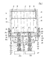
- the pouring device shown in the drawing has a pouring housing 10, the pouring opening 11 of which can be closed with strip-like drapes 12.
- a lid opening device 13 is attached, the two levers 14, which are pivotably mounted in the upper part of the pouring opening 11 and have a hook-shaped design lower end 15 is formed.
- the levers 14 are held in their normal position by springs 16 and serve to receive actuating pins attached to the side of large-scale waste containers and, when the large-volume waste container is tipped into the pouring opening 11, to hold back the cover of this container and thereby open it.
- the two levers 14 are connected to a crossbar 17, which is provided with buffer pads 18 and when emptying smaller containers, these buffer pads 18 lie against the container wall and the smaller containers tip over the pouring opening 11 prevented.
- the novel lifting-tilting device 20 has two individual lifting-tilting devices 20a and 20b, which have the same structure and a symmetrical arrangement with respect to the vertical center plane of the pouring device 10. With regard to the same structure of both single lift and tilt devices 20a and 20b, only the structure of one of these single lift and tilt devices is explained below.
- Both single lift and tilt devices 20a and 20b have a common pivot shaft 21, which is divided in the central region and for each single lift and tilt device 20a and 20b forms a pivot shaft part 21a and 21b.
- a swing arm 22 is attached to each of these swing shaft towers 21a and 21b.
- These swivel arms 22 consist of two swivel arm parts 22a and 22b fastened at a lateral distance on the respective swivel shaft part 21a or 21b, which extend parallel to one another and open a lifting cylinder 23 between them.
- Each of the swivel arms 22 carries a lifting frame 24, each consisting of two vertical support parts 25a and 25b, at the upper end of which a lifting beam 26 and at the lower end of which an abutment plate 27 is attached.
- the lifting beam 26 carries tooth-like receiving and supporting parts 28 which extend upwards and a centering insert 29 at its outer end, i.e. towards the outside of the pouring device 10.
- the lifting beam 26 and the abutment plates 27 of both individual lifting and tilting devices 20a and 20b are arranged in such a way that they are aligned with one another in the rest position, lifting end position and in the tipping end position of both individual lifting and tipping devices 20a and 20b.
- a holding and locking bar 32 is fixedly mounted on each swivel shaft part 21a and 21b in a vertical position opposite to the walking beam 26, which accordingly follows the swivel movement of each of the swivel arms 22.
- each swivel shaft part 21a and 21b carries on its outer end region a swivel limiting lever 35 which, in the end tilting position of the respective single-stroke tilting device 20a or 20b, engages with a limiting buffer 36 which is attached to the bulk housing and which - as shown in detail in FIG. 6 - Can be connected to a pressure relief valve actuated by the pivot limiting lever 35.
- a hydraulic system is provided for the actuation of the lifting and tilting device, which has an actuating valve 37a and 37b for each individual lifting and tilting device 20a and for the selection for individual operation or joint operation of both individual lifting and tilting devices 20a and 20b contains a shut-off and diverter valve 38.
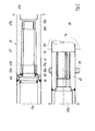
- each individual lifting and tilting device can also be equipped with a travel locking hook 39, which is pivotably mounted on the inside of a swivel arm part 22a and, with the lifting frame 24 partially raised, via the piston rod 23a of the lifting cylinder 23 is hung with the lower link pair 31a, 31b connecting rod 23b.
- This raised locked S medium- development of the lifting frame 24 is particularly suitable for mounted on refuse trucks lifting and tipping apparatus to hold the lifting frame when driving the refuse vehicle at a safe distance from the ground.
- a further supplementary securing is possible according to FIG. 5 in that a locking pawl 40 is pivotally mounted between the supports 25a and 25b of the lifting frame, which pawl is due to its own weight in the end position of the respective single-stroke-tilting device 20a or 20b is pivoted in such a way that it engages around a pin 40a attached to the pivot arm 22 and thereby prevents the lifting frame 24 from lifting off the respective pivot arm 22 when the lifting cylinder 23 is depressurized during the shaking movement.
- Lifting can only start when the respective single-lift-tilt Device 20a or 20b is pivoted back out of the pouring opening 11 to such an extent that the locking hook 40 releases the respective bolt 40a.
- the respective swivel limit lever 35 is fixedly connected to the designed as a splined hub 41 end region of the respective pivot shaft portion 21a and 21b and set excluded to as tooth wave, or partial wave 'formed output shaft of the respective pivoting drive 33rd
- the pivot limiting lever 35 carries an abutment plate 42 which moves against an abutment buffer 36 on the bed housing.
- the actuating member 44 of a pressure relief valve 43 engages through the abutment buffer 36 in order to adjust the pressure relief valve 43 against the action of a spring.
- the pivot limiting lever 35 carries an adjusting screw 45 in the area of its abutment plate 42.
- the adjustment can be carried out in such a way that the changeover time of the pressure relief valve 43 is reached when the abutment plate 42 is still a short distance away 4G from the abutment buffer 36. If necessary, the adjusting screw can also be used to set up a vibrating effect using the pressure relief valve.
- the pivot shaft 21 can be designed as a hollow shaft.
- One pivot shaft part 21 carries at its end lying towards the center of the pivot shaft a connecting and bearing pin 47 which is axially fixedly inserted into the end of the threshold part 21a.
- This connecting and bearing pin 47 has two axially spaced cylindrical sections 47a and 47b, of which the smaller diameter cylindrical section 47b is arranged at the free end of the connecting and bearing pin 47.
- a needle bearing 48a and 48b is placed on each of these cylindrical sections 47a and 47b.
- a plastic ring with the same outer diameter as the pivot shaft part 21a and a radial sealing ring 50 are placed on the connecting and pivot pin 47.
- the pivot shaft portion 21b is formed in the central region of the pivot shaft 21 as a receiving socket 51 for the V erb i ndungs- and pivot pin 47 and, accordingly, includes a cylindrical bore portion 51a for receiving the needle bearing 48a and a cylindrical portion 51b for receiving the needle bearing 48b.
- a section 51c is formed between these two cylindrical sections 51a and 51b, the inside diameter of which is larger than the outside diameter of the section accommodated there tes of the connecting and pivot pin 47. In this way, an annular space for receiving lubricant is formed, which is externally accessible by a chmiernippel S.
- a further enlarged bore section 51d for receiving the radial sealing ring 50 and a smooth, flat end face for contact with the plastic ring 49 are formed.
- the two swivel shaft parts 21a and 21b are held axially together (see FIG. 1) by the seat of the needle bearings 48a and 48b and by the swivel drives 33 which are attached to the swivel shaft 21 from both sides and are held on the bulkhead housing with flanges.
- a hydraulic pressure medium system for actuating and controlling the lifting and tilting device according to FIGS. 1 to 7, which contains two pressure medium circuits A and B designed in the same way.
- Each of these pressure medium circuits A and B has a pressure medium source, which in the example shown can be formed by a branch 52a or 52b of a pressure-independent flow divider in connection with a pressure medium pump 52c arranged upstream of this flow divider.
- this pressure medium source by means of a twin pressure medium pump, of which a single pump is connected to one of the pressure medium circuits A and B, respectively.
- pressure medium circuit A leads from this pressure medium source 52, 52a a pressure medium supply line 53a or 53b to the respective control valve 37a or 37b.
- the respective pressure medium supply line 54a or 54b is connected to this control valve 37a or 37b.
- the pressure medium supply line 54a leads to the cylinders 34 of the actuating drive 33 and lifting cylinders 23 of the single-lift-tilting device 20a connected in parallel, while the pressure medium supply line 54b in a symmetrical arrangement to the parallel connection of swivel drive cylinders 34 and lifting cylinders 23 of the single-lift-tilting devices Device 20b leads.
- a pressure relief valve 43 with an actuating element 44 is connected to each of the pressure medium supply lines 54a and 54b.
- pressure relief lines 55a and 55b lead to a pressure medium return valve 56a and 56b, which is inserted into the pressure medium return line 57a and 57b, in order to improve the pressure medium return and thus the backward movement of the cylinder-piston units 23 and 34.
- a pressure medium short-circuit line 58a or 58b also leads from the control valve 37a or 37b to the respective pressure medium return valve 56a or 56b.
- the pressure medium return lines 57a and 57b lead into a pressure medium reservoir 59, from which the pressure medium pump 52c draws in the quantity of pressure medium required for the system and via the respective branch 52a or 52b of the flow divider into the pressure medium circuit A or the pressure medium circuit B. introduces.
- shut-off and switching valve 38 is inserted between the pressure medium supply lines 54a and 54b.
- shut-off and switching valve 38 are in the shut-off position and the control valves 37a and 37b are in the zero position. With this valve position, the pressure medium coming from the pressure medium source 52a flows in the pressure medium circuit A via the pressure medium supply line 53a and the passage formed in the zero position to the control valve 37a to the short-circuit line 58a, from there through the return valve 56a into the return line 57a and from there back to the pressure medium reservoir 59 to get.
- the flow in the pressure medium circuit B runs from the pressure medium source 52b via the pressure medium feed line 53b, the control valve 37b, the short circuit line 38a, the return valve 56b into the return line 37b and from there back to the pressure medium reservoir 59.
- the control valve 37a becomes the working position brought, the pressure medium course in the pressure medium circuit A is from the pressure medium source 52a via the pressure medium supply line 53a to the pressure medium supply line 54a and from there to the cylinder-piston units 23 and 34.
- These two units are coordinated with one another with their piston cross-section in such a way that, according to the initial power to be provided by the respective unit, the lifting cylinder 23 is designed to be stronger than the swivel drive cylinder 34.
- the cylinder 23 is first actuated until the lifting process is almost complete and the tilting process is initiated by means of the swivel drive cylinder 34 due to the slight increase in pressure that occurs.
- the adjusting screw 45 of the swivel limiting lever 35 hits the actuating member 44 of the pressure relief valve 43 (see FIG. 6).
- the pressure relief valve 43 which was previously in the closed position, is then brought into a partially open position against the action of its adjusting spring, so that pressure relief in the pressure medium supply line 54a takes place via the pressure relief line 55a to the pressure medium return valve 56a.
- control distance 46 between the actuation of the pressure relief valve 43 and the end position of the swivel limiting lever on the abutment buffer 36 is set sufficiently narrow, only such a pressure relief in the pressure medium supply line 54a will take place that the residual pressure is sufficient to reduce the individual stroke To keep the tipping device together with the vessel to be emptied in the end tipping position.
- you set the control distance 46 continues, so that the adjusting screw 45 hits the actuating element 44 of the pressure relief valve 43 earlier, then the pressure relief valve 43 is opened so far that a strong pressure drop occurs in the pressure medium supply line 54a.
- This strong drop in pressure medium causes the single-stroke tilting device with the container to be emptied to pivot back by an amount such that the pressure relief valve is closed again. In this way, by continuously actuating and releasing the pressure relief valve 43 by the swivel limiting lever 35, a kind of shaking movement can be caused.
- the control valve 37a To pivot back and set down a container, the control valve 37a is to be brought into its return position III. In this position the pressure medium supply! Line 53a connected to the return line 57a and the pressure medium supply line 54a to the short-circuit line 58a. The pressure medium coming from the pressure medium source 52a via the pressure medium feed line 53a then flows out through the return valve 56a, whereby it exerts a suction effect on the short-circuit line 58a (venturi formation), thereby not only causing the pressure medium from the pressure medium supply line and from the cylinders 23 and 34 to drain, but also to vacuum, especially until the emptied container is set down.
- This workflow in the pressure medium circuit A has no e inl to the pressure medium circuit B, either on the pressure buildup in the pressure medium circuit B flowing yet to possibly in the pressure medium circuit B amount of pressure medium.
- control valve 37b is actuated in the pressure medium circuit B for the single-stroke-tilting device 20b in a corresponding manner as explained above, the corresponding work processes occur in the pressure medium circuit B without affecting the pressure medium circuit A.
- shut-off and switching valve 38 If the shut-off and switching valve 38 is brought into the connecting position, a direct connection between the pressure medium supply lines 54a and 54b is created, and thus all cylinder-piston units 23 and 24 of the entire lifting and tilting device 20 are connected in parallel. Then the control valve 37a brought into working position, then both D ruck medium feed lines 54a and 54b fed from the pressure medium source 52a via the pressure medium forward line 53a. This means that in each case both lifting cylinders 23 and both swivel drive cylinders 34 are charged with the same pressure medium flow rate, as in single control only a lifting cylinder 23, and a swivel drive cylinder 34.
- the operation speed of the entire lift-tilt rVorrichtun g is about only half as large as that of the individually controlled single lift and tilt device 20a or 20b.
- shut-off and changeover valve 38 is provided, which is arranged on one side of the emptying device.
- two shut-off and diverter valves could be provided, one on each side of the emptying device. These two shut-off and diverter valves would then be designed in an analogous manner and arranged in the hydraulic system, as is known, for example, for electrical changeover switches in electrical light installation systems. The device could then be switched from one operating mode to the other at any shut-off and diverter valve.
- the invention can also be carried out using a pneumatic pressure medium system.
Priority Applications (1)
| Application Number | Priority Date | Filing Date | Title |
|---|---|---|---|
| AT79104094T ATE2733T1 (de) | 1978-10-31 | 1979-10-23 | Hub-kipp- oder kippvorrichtung zum entleeren von behaeltern unterschiedlicher groesse. |
Applications Claiming Priority (2)
| Application Number | Priority Date | Filing Date | Title |
|---|---|---|---|
| DE2847259 | 1978-10-31 | ||
| DE19782847259 DE2847259A1 (de) | 1978-10-31 | 1978-10-31 | Hub-kipp- oder kippvorrichtung zum entleeren von behaeltern unterschiedlicher groesse |
Publications (2)
| Publication Number | Publication Date |
|---|---|
| EP0010719A1 true EP0010719A1 (fr) | 1980-05-14 |
| EP0010719B1 EP0010719B1 (fr) | 1983-03-09 |
Family
ID=6053522
Family Applications (1)
| Application Number | Title | Priority Date | Filing Date |
|---|---|---|---|
| EP79104094A Expired EP0010719B1 (fr) | 1978-10-31 | 1979-10-23 | Dispositif pour soulever et basculer ou dispositif pour basculer des récipients de grandeurs différentes dans le but de les vider |
Country Status (17)
| Country | Link |
|---|---|
| US (1) | US4305693A (fr) |
| EP (1) | EP0010719B1 (fr) |
| JP (1) | JPS5561503A (fr) |
| AT (1) | ATE2733T1 (fr) |
| AU (1) | AU525195B2 (fr) |
| BR (1) | BR7907068A (fr) |
| CA (1) | CA1118704A (fr) |
| CS (1) | CS230565B2 (fr) |
| DD (1) | DD146929A5 (fr) |
| DE (2) | DE2847259A1 (fr) |
| DK (1) | DK151560C (fr) |
| ES (1) | ES485586A1 (fr) |
| NO (1) | NO153924C (fr) |
| PL (1) | PL117599B1 (fr) |
| PT (1) | PT70391A (fr) |
| YU (1) | YU42654B (fr) |
| ZA (1) | ZA795811B (fr) |
Cited By (14)
| Publication number | Priority date | Publication date | Assignee | Title |
|---|---|---|---|---|
| WO1985003689A2 (fr) * | 1984-02-20 | 1985-08-29 | Zöller-Kipper GmbH | Installation de vidage de conteneurs, en particulier de conteneurs d'ordures |
| WO1986000601A1 (fr) * | 1984-07-04 | 1986-01-30 | Helmut Sieke | Vehicule de transport d'ordures |
| EP0386569A1 (fr) * | 1989-03-08 | 1990-09-12 | OTTO LIFT-SYSTEME GmbH | Dispositif pour vider des récipients, en particulier d'ordures |
| US5004392A (en) * | 1984-02-20 | 1991-04-02 | Zoller-Kipper Gmbh | Device for emptying containers, especially refuse bins |
| EP0423682A1 (fr) * | 1989-10-18 | 1991-04-24 | Waste Hoists Limited | Véhicule de ramassage, appareillage destiné À être utilisé avec celui-ci et méthode de ramassage de matériel |
| EP0463386A1 (fr) * | 1990-06-26 | 1992-01-02 | Antonicelli S.P.A. | Dispositif de basculement de récipients destiné à accrocher automatiquement des poubelles équipées d'un rebord et à les renverser dans la benne d'un véhicule à moteur |
| EP0493571A1 (fr) * | 1990-07-24 | 1992-07-08 | Stephen Wayne Holtom | Bras de chargement de dechets. |
| US5503512A (en) * | 1992-06-22 | 1996-04-02 | Bayne Machine Works, Inc. | Residential refuse collection cart lifter with universal features |
| EP0820941A1 (fr) * | 1996-07-26 | 1998-01-28 | C.L.G.Inversiones,S.L. | Dispositif de levage et de basculement pour vider des poubelles |
| NL1004577C2 (nl) * | 1996-11-20 | 1998-05-25 | Geesink Bv | Inrichting voor het heffen en/of kantelen van containers. |
| DE19729297A1 (de) * | 1997-07-09 | 1999-01-14 | Zoeller Kipper | Verfahren und Vorrichtung zum Entleeren von Müllbehältern in einen Sammelbehälter |
| US6167795B1 (en) | 1992-06-22 | 2001-01-02 | Bayne Machine Works, Inc. | Container box and lifter features |
| US6607572B2 (en) | 2001-02-24 | 2003-08-19 | Dyson Limited | Cyclonic separating apparatus |
| CN111731887A (zh) * | 2019-07-17 | 2020-10-02 | 天津市深宏科技开发有限公司 | 智能自动装载系统及方法 |
Families Citing this family (16)
| Publication number | Priority date | Publication date | Assignee | Title |
|---|---|---|---|---|
| EP0103572A1 (fr) * | 1982-03-18 | 1984-03-28 | Wastemovers Pty.Limited | Dispositif a usages multiples de maniement de recipients |
| US4580940A (en) * | 1984-08-15 | 1986-04-08 | American Refuse Systems, Inc. | Refuse container lift/dump apparatus |
| DE3527022A1 (de) * | 1984-08-21 | 1986-03-06 | Zöller-Kipper GmbH, 6500 Mainz | Kipp- oder hubkipp-vorrichtung zum entleeren von behaeltern in sammelbehaelter, vorzugsweise muellbehaelter in den sammelbehaelter eines muellfahrzeugs |
| US4687405A (en) * | 1985-06-24 | 1987-08-18 | Olney David I | Trash can dumping apparatus |
| FR2614011B1 (fr) * | 1987-04-15 | 1991-09-06 | Plastic Omnium Cie | Mecanisme de prehension de bacs roulants dans un dispositif de basculement de bacs pour leur vidage dans un camion de collecte de dechets, notamment d'ordures menageres |
| GB8724360D0 (en) * | 1987-10-17 | 1987-11-18 | Allen Motor Bodies Ltd Jack | Collection vehicle & method of tipping bin |
| DE3804090A1 (de) * | 1988-02-10 | 1989-08-24 | Edelhoff Polytechnik | Muellsammelfahrzeug |
| DE3830227A1 (de) * | 1988-09-06 | 1990-03-15 | Zoeller Kipper | Hubkippvorrichtung zum entleeren von behaeltern in die einschuettoeffnung eines sammelbehaelters, insbesondere zum entleeren von muellbehaeltern in den sammelbehaelter eines muellfahrzeuges |
| DE4128955C1 (fr) * | 1991-08-30 | 1992-11-05 | Zoeller Kipper | |
| US5879015A (en) * | 1992-02-10 | 1999-03-09 | Ramsey; Michael P. | Method and apparatus for receiving material |
| CA2170215C (fr) * | 1995-03-28 | 2001-12-04 | Ronald E. Christenson | Manutentionneur de bacs basculants |
| EP1077890B1 (fr) * | 1998-05-11 | 2002-12-18 | Zöller Holding GmbH | Dispositif de levage et de culbutage |
| NL2004148C2 (nl) | 2010-01-26 | 2011-07-27 | Terberg Machines | Beladingssyssteem, vuilnisauto en werkwijze daarvoor. |
| CN102398755B (zh) * | 2011-11-02 | 2013-07-24 | 长沙中联重科环卫机械有限公司 | 翻桶装置和后装压缩式垃圾车 |
| FR2998280B1 (fr) * | 2012-11-20 | 2016-12-30 | Pb Environnement | Vehicule de collecte de dechets avec leve-conteneurs ameliore |
| US10239689B2 (en) | 2015-07-27 | 2019-03-26 | The Heil Co. | Multi-use garbage truck |
Citations (4)
| Publication number | Priority date | Publication date | Assignee | Title |
|---|---|---|---|---|
| DE1017978B (de) * | 1956-05-08 | 1957-10-17 | Hans Zoeller | Muelltonnenkippvorrichtung |
| FR2153053A1 (fr) * | 1971-09-17 | 1973-04-27 | Streuber Sulo Eisenwerk F | |
| DE2515929A1 (de) * | 1975-04-11 | 1976-10-21 | Edelhoff Staedtereinigung | Hubkipp- oder kippvorrichtung zum entleeren von muellbehaeltern unterschiedlicher groesse |
| DE2654542A1 (de) * | 1976-12-02 | 1978-06-08 | Zoeller Kipper | Hub-kipp-vorrichtung fuer behaelter, insbesondere zum entleeren von muellgefaessen in muellsammelbehaelter |
Family Cites Families (8)
| Publication number | Priority date | Publication date | Assignee | Title |
|---|---|---|---|---|
| GB942792A (en) * | 1959-03-12 | 1963-11-27 | Leonard Wilfred Williams Evans | Refuse collecting vehicle |
| DE1193418B (de) * | 1962-04-06 | 1965-05-20 | Eisenwerk Streuber & Lohmann G | Hubkippvorrichtung zum Entleeren von Muellgefaessen in staubfreie Schuettvorrichtungen an Muellsammelwagen |
| AT243183B (de) * | 1963-05-24 | 1965-10-25 | Maschf Augsburg Nuernberg Ag | Ladevorrichtung für Müllwagen |
| DE1201756B (de) * | 1963-09-21 | 1965-09-23 | Kloeckner Humboldt Deutz Ag | Hub- und Kippvorrichtung zum Entleeren von Muellgefaessen in Muellwagen |
| DE1240776B (de) * | 1964-02-15 | 1967-05-18 | Elisabeth Zoeller Geb Kehl | Hubkippvorrichtung fuer Behaelter, insbesondere zum Entleeren von Muellgefaessen in Muellwagen |
| DE1231616B (de) * | 1964-07-24 | 1966-12-29 | Heinz Fritz Reichenkron Dipl I | Hub-Kippvorrichtung an Muellsammelwagen zur staubfreien Entleerung von Muellgefaessen verschiedener Groesse |
| DE1248541B (de) * | 1965-08-12 | 1967-08-24 | Streuber Sulo Eisenwerk F | Hubkippvorrichtung zum Entleeren von Muellgefaessen in staubfreie Einschuettvorrichtungen an Muellsammelwagen |
| US3738516A (en) * | 1972-07-31 | 1973-06-12 | L Wells | Container lifting mechanism |
-
1978
- 1978-10-31 DE DE19782847259 patent/DE2847259A1/de not_active Ceased
-
1979
- 1979-10-23 DE DE7979104094T patent/DE2965001D1/de not_active Expired
- 1979-10-23 EP EP79104094A patent/EP0010719B1/fr not_active Expired
- 1979-10-23 AT AT79104094T patent/ATE2733T1/de not_active IP Right Cessation
- 1979-10-24 NO NO793414A patent/NO153924C/no unknown
- 1979-10-24 DK DK447479A patent/DK151560C/da not_active IP Right Cessation
- 1979-10-30 ZA ZA00795811A patent/ZA795811B/xx unknown
- 1979-10-30 CA CA000338719A patent/CA1118704A/fr not_active Expired
- 1979-10-30 PT PT70391A patent/PT70391A/pt unknown
- 1979-10-30 AU AU52320/79A patent/AU525195B2/en not_active Ceased
- 1979-10-30 CS CS797375A patent/CS230565B2/cs unknown
- 1979-10-30 US US06/089,518 patent/US4305693A/en not_active Expired - Lifetime
- 1979-10-31 ES ES485586A patent/ES485586A1/es not_active Expired
- 1979-10-31 JP JP14002579A patent/JPS5561503A/ja active Granted
- 1979-10-31 PL PL1979219360A patent/PL117599B1/pl unknown
- 1979-10-31 BR BR7907068A patent/BR7907068A/pt not_active IP Right Cessation
- 1979-10-31 DD DD79216591A patent/DD146929A5/de not_active IP Right Cessation
- 1979-10-31 YU YU2661/79A patent/YU42654B/xx unknown
Patent Citations (4)
| Publication number | Priority date | Publication date | Assignee | Title |
|---|---|---|---|---|
| DE1017978B (de) * | 1956-05-08 | 1957-10-17 | Hans Zoeller | Muelltonnenkippvorrichtung |
| FR2153053A1 (fr) * | 1971-09-17 | 1973-04-27 | Streuber Sulo Eisenwerk F | |
| DE2515929A1 (de) * | 1975-04-11 | 1976-10-21 | Edelhoff Staedtereinigung | Hubkipp- oder kippvorrichtung zum entleeren von muellbehaeltern unterschiedlicher groesse |
| DE2654542A1 (de) * | 1976-12-02 | 1978-06-08 | Zoeller Kipper | Hub-kipp-vorrichtung fuer behaelter, insbesondere zum entleeren von muellgefaessen in muellsammelbehaelter |
Cited By (22)
| Publication number | Priority date | Publication date | Assignee | Title |
|---|---|---|---|---|
| WO1985003689A2 (fr) * | 1984-02-20 | 1985-08-29 | Zöller-Kipper GmbH | Installation de vidage de conteneurs, en particulier de conteneurs d'ordures |
| WO1985003689A3 (fr) * | 1984-02-20 | 1985-10-24 | Zoeller Kipper | Installation de vidage de conteneurs, en particulier de conteneurs d'ordures |
| US5004392A (en) * | 1984-02-20 | 1991-04-02 | Zoller-Kipper Gmbh | Device for emptying containers, especially refuse bins |
| WO1986000601A1 (fr) * | 1984-07-04 | 1986-01-30 | Helmut Sieke | Vehicule de transport d'ordures |
| EP0386569A1 (fr) * | 1989-03-08 | 1990-09-12 | OTTO LIFT-SYSTEME GmbH | Dispositif pour vider des récipients, en particulier d'ordures |
| GB2237791B (en) * | 1989-10-18 | 1994-01-26 | Waste Hoists Ltd | Collection vehicle, apparatus for use in the vehicle and method of collecting material |
| US5145305A (en) * | 1989-10-18 | 1992-09-08 | Waste Hoists Limited | Collection vehicle, apparatus for use in the vehicle and method of collecting material |
| EP0423682A1 (fr) * | 1989-10-18 | 1991-04-24 | Waste Hoists Limited | Véhicule de ramassage, appareillage destiné À être utilisé avec celui-ci et méthode de ramassage de matériel |
| GB2237791A (en) * | 1989-10-18 | 1991-05-15 | Waste Hoists Ltd | Refuse collection vehicle. |
| EP0463386A1 (fr) * | 1990-06-26 | 1992-01-02 | Antonicelli S.P.A. | Dispositif de basculement de récipients destiné à accrocher automatiquement des poubelles équipées d'un rebord et à les renverser dans la benne d'un véhicule à moteur |
| EP0493571A1 (fr) * | 1990-07-24 | 1992-07-08 | Stephen Wayne Holtom | Bras de chargement de dechets. |
| EP0493571A4 (en) * | 1990-07-24 | 1994-06-22 | Stephen Wayne Holtom | Refuse loader arm |
| US6167795B1 (en) | 1992-06-22 | 2001-01-02 | Bayne Machine Works, Inc. | Container box and lifter features |
| US5503512A (en) * | 1992-06-22 | 1996-04-02 | Bayne Machine Works, Inc. | Residential refuse collection cart lifter with universal features |
| EP0820941A1 (fr) * | 1996-07-26 | 1998-01-28 | C.L.G.Inversiones,S.L. | Dispositif de levage et de basculement pour vider des poubelles |
| NL1004577C2 (nl) * | 1996-11-20 | 1998-05-25 | Geesink Bv | Inrichting voor het heffen en/of kantelen van containers. |
| EP0844198A1 (fr) | 1996-11-20 | 1998-05-27 | Geesink B.V. | Dispositif pour soulever et/ou faire basculer des récipients |
| DE19729297A1 (de) * | 1997-07-09 | 1999-01-14 | Zoeller Kipper | Verfahren und Vorrichtung zum Entleeren von Müllbehältern in einen Sammelbehälter |
| WO1999002433A1 (fr) | 1997-07-09 | 1999-01-21 | Zöller-Kipper GmbH | Procede et dispositif pour vider des conteneurs a ordures dans un conteneur collecteur |
| DE19729297C2 (de) * | 1997-07-09 | 1999-07-15 | Zoeller Kipper | Verfahren und Vorrichtung zum Entleeren von Müllbehältern in einen Sammelbehälter |
| US6607572B2 (en) | 2001-02-24 | 2003-08-19 | Dyson Limited | Cyclonic separating apparatus |
| CN111731887A (zh) * | 2019-07-17 | 2020-10-02 | 天津市深宏科技开发有限公司 | 智能自动装载系统及方法 |
Also Published As
| Publication number | Publication date |
|---|---|
| DK447479A (da) | 1980-05-01 |
| PL117599B1 (en) | 1981-08-31 |
| EP0010719B1 (fr) | 1983-03-09 |
| NO153924C (no) | 1986-06-18 |
| JPS5561503A (en) | 1980-05-09 |
| YU266179A (en) | 1983-12-31 |
| AU525195B2 (en) | 1982-10-21 |
| NO153924B (no) | 1986-03-10 |
| NO793414L (no) | 1980-05-02 |
| PL219360A1 (fr) | 1980-06-02 |
| JPH0124681B2 (fr) | 1989-05-12 |
| BR7907068A (pt) | 1980-06-24 |
| ZA795811B (en) | 1980-10-29 |
| CS230565B2 (en) | 1984-08-13 |
| DE2965001D1 (en) | 1983-04-14 |
| PT70391A (de) | 1979-11-01 |
| AU5232079A (en) | 1980-05-08 |
| CA1118704A (fr) | 1982-02-23 |
| YU42654B (en) | 1988-10-31 |
| ES485586A1 (es) | 1980-06-16 |
| ATE2733T1 (de) | 1983-03-15 |
| DE2847259A1 (de) | 1980-05-08 |
| DK151560B (da) | 1987-12-14 |
| DD146929A5 (de) | 1981-03-11 |
| US4305693A (en) | 1981-12-15 |
| DK151560C (da) | 1988-05-30 |
Similar Documents
| Publication | Publication Date | Title |
|---|---|---|
| EP0010719B1 (fr) | Dispositif pour soulever et basculer ou dispositif pour basculer des récipients de grandeurs différentes dans le but de les vider | |
| DE2654542C3 (de) | Hub-Kipp-Vorrichtung für Behälter, insbesondere zum Entleeren von Müllgefäßen in Müllsammelbehälter. | |
| DE3509171A1 (de) | Vorrichtung zum kompaktieren von festen abfaellen | |
| DE2708251C2 (de) | Lastkraftfahrzeug | |
| DE4005968C2 (de) | Müllsammelfahrzeug | |
| DE2515929C2 (de) | Vorrichtung zum Entleeren von Müllbehältern | |
| DE4441551C1 (de) | Vorrichtung zum hängenden Anheben und Entleeren von Behältern, Containern od. dgl. | |
| DE649350C (de) | Muellsammelbehaelter | |
| EP0143197A1 (fr) | Disposition pour actionner une benne preneuse | |
| DE102021117999B3 (de) | Hub-Kipp-Vorrichtung | |
| DE1248541B (de) | Hubkippvorrichtung zum Entleeren von Muellgefaessen in staubfreie Einschuettvorrichtungen an Muellsammelwagen | |
| EP0690014B1 (fr) | Dispositif de levage et de basculement pour vider des poubelles | |
| EP0574374A1 (fr) | Récipient collecteur d'ordures avec compartiment à volume variable | |
| DE2616813A1 (de) | Vorrichtung, insbesondere fuer kraftfahrzeuge, zum aufnehmen und absetzen sowie kippen von behaeltern | |
| EP0338492A2 (fr) | Benne pour la collecte séparée de matériaux différents | |
| EP0386569A1 (fr) | Dispositif pour vider des récipients, en particulier d'ordures | |
| DD296658A5 (de) | Muellsammelfahrzeug | |
| DE3016146A1 (de) | Schuerfkuebel fuer die befestigung an einem fahrzeug | |
| DE2817599A1 (de) | Fahrzeug, das mit einer einrichtung fuer das aufnehmen vom boden, das transportieren, das kippen und das abstellen auf dem boden eines behaelters oder kastens, insbesondere eines behaelters zur aufnahme von abfaellen, ausgestattet ist | |
| DE4331750A1 (de) | Müllsammelfahrzeug | |
| EP0763488B1 (fr) | Véhicule de ramassage d'ordures | |
| DE19952483C1 (de) | Verriegelungsvorrichtung für nebeneinander angeordnete Hubwagen | |
| DE2524622A1 (de) | Geraet zum entleeren oben offener behaelter, insbesondere von sinkschachteimern | |
| DE4315412A1 (de) | Hub-Kippvorrichtung eines Müllsammelfahrzeuges | |
| DE1193418B (de) | Hubkippvorrichtung zum Entleeren von Muellgefaessen in staubfreie Schuettvorrichtungen an Muellsammelwagen |
Legal Events
| Date | Code | Title | Description |
|---|---|---|---|
| PUAI | Public reference made under article 153(3) epc to a published international application that has entered the european phase |
Free format text: ORIGINAL CODE: 0009012 |
|
| AK | Designated contracting states |
Designated state(s): AT BE CH DE FR GB IT NL SE |
|
| 17P | Request for examination filed |
Effective date: 19801111 |
|
| ITF | It: translation for a ep patent filed |
Owner name: MODIANO & ASSOCIATI S.R.L. |
|
| GRAA | (expected) grant |
Free format text: ORIGINAL CODE: 0009210 |
|
| AK | Designated contracting states |
Designated state(s): AT BE CH DE FR GB IT NL SE |
|
| REF | Corresponds to: |
Ref document number: 2733 Country of ref document: AT Date of ref document: 19830315 Kind code of ref document: T |
|
| REF | Corresponds to: |
Ref document number: 2965001 Country of ref document: DE Date of ref document: 19830414 |
|
| ET | Fr: translation filed | ||
| PLBI | Opposition filed |
Free format text: ORIGINAL CODE: 0009260 |
|
| 26 | Opposition filed |
Opponent name: FAUN-WERKE NUERNBERG KOMMUNALFAHRZEUGE UND LASTKRA Effective date: 19831209 |
|
| PLBN | Opposition rejected |
Free format text: ORIGINAL CODE: 0009273 |
|
| STAA | Information on the status of an ep patent application or granted ep patent |
Free format text: STATUS: OPPOSITION REJECTED |
|
| 27O | Opposition rejected |
Effective date: 19850131 |
|
| NLR2 | Nl: decision of opposition | ||
| ITTA | It: last paid annual fee | ||
| EAL | Se: european patent in force in sweden |
Ref document number: 79104094.2 |
|
| PGFP | Annual fee paid to national office [announced via postgrant information from national office to epo] |
Ref country code: FR Payment date: 19971016 Year of fee payment: 19 |
|
| PGFP | Annual fee paid to national office [announced via postgrant information from national office to epo] |
Ref country code: GB Payment date: 19971020 Year of fee payment: 19 |
|
| PGFP | Annual fee paid to national office [announced via postgrant information from national office to epo] |
Ref country code: SE Payment date: 19971021 Year of fee payment: 19 Ref country code: BE Payment date: 19971021 Year of fee payment: 19 Ref country code: AT Payment date: 19971021 Year of fee payment: 19 |
|
| PGFP | Annual fee paid to national office [announced via postgrant information from national office to epo] |
Ref country code: CH Payment date: 19971022 Year of fee payment: 19 |
|
| PGFP | Annual fee paid to national office [announced via postgrant information from national office to epo] |
Ref country code: NL Payment date: 19971029 Year of fee payment: 19 |
|
| PGFP | Annual fee paid to national office [announced via postgrant information from national office to epo] |
Ref country code: DE Payment date: 19971117 Year of fee payment: 19 |
|
| PG25 | Lapsed in a contracting state [announced via postgrant information from national office to epo] |
Ref country code: GB Free format text: LAPSE BECAUSE OF NON-PAYMENT OF DUE FEES Effective date: 19981023 Ref country code: AT Free format text: LAPSE BECAUSE OF NON-PAYMENT OF DUE FEES Effective date: 19981023 |
|
| PG25 | Lapsed in a contracting state [announced via postgrant information from national office to epo] |
Ref country code: SE Free format text: LAPSE BECAUSE OF NON-PAYMENT OF DUE FEES Effective date: 19981024 |
|
| PG25 | Lapsed in a contracting state [announced via postgrant information from national office to epo] |
Ref country code: CH Free format text: LAPSE BECAUSE OF NON-PAYMENT OF DUE FEES Effective date: 19981031 Ref country code: BE Free format text: LAPSE BECAUSE OF NON-PAYMENT OF DUE FEES Effective date: 19981031 |
|
| BERE | Be: lapsed |
Owner name: ZOLLER-KIPPER G.M.B.H. Effective date: 19981031 |
|
| PG25 | Lapsed in a contracting state [announced via postgrant information from national office to epo] |
Ref country code: NL Free format text: LAPSE BECAUSE OF NON-PAYMENT OF DUE FEES Effective date: 19990501 |
|
| REG | Reference to a national code |
Ref country code: CH Ref legal event code: PL |
|
| GBPC | Gb: european patent ceased through non-payment of renewal fee |
Effective date: 19981023 |
|
| EUG | Se: european patent has lapsed |
Ref document number: 79104094.2 |
|
| PG25 | Lapsed in a contracting state [announced via postgrant information from national office to epo] |
Ref country code: FR Free format text: LAPSE BECAUSE OF NON-PAYMENT OF DUE FEES Effective date: 19990630 |
|
| NLV4 | Nl: lapsed or anulled due to non-payment of the annual fee |
Effective date: 19990501 |
|
| REG | Reference to a national code |
Ref country code: FR Ref legal event code: ST |
|
| PG25 | Lapsed in a contracting state [announced via postgrant information from national office to epo] |
Ref country code: DE Free format text: LAPSE BECAUSE OF NON-PAYMENT OF DUE FEES Effective date: 19990803 |