EP0010719A1 - Lifting/tipping or tipping apparatus for emptying containers of varying sizes - Google Patents
Lifting/tipping or tipping apparatus for emptying containers of varying sizes Download PDFInfo
- Publication number
- EP0010719A1 EP0010719A1 EP79104094A EP79104094A EP0010719A1 EP 0010719 A1 EP0010719 A1 EP 0010719A1 EP 79104094 A EP79104094 A EP 79104094A EP 79104094 A EP79104094 A EP 79104094A EP 0010719 A1 EP0010719 A1 EP 0010719A1
- Authority
- EP
- European Patent Office
- Prior art keywords
- pressure medium
- lifting
- tilting
- devices
- containers
- Prior art date
- Legal status (The legal status is an assumption and is not a legal conclusion. Google has not performed a legal analysis and makes no representation as to the accuracy of the status listed.)
- Granted
Links
Images


Classifications
-
- B—PERFORMING OPERATIONS; TRANSPORTING
- B65—CONVEYING; PACKING; STORING; HANDLING THIN OR FILAMENTARY MATERIAL
- B65F—GATHERING OR REMOVAL OF DOMESTIC OR LIKE REFUSE
- B65F3/00—Vehicles particularly adapted for collecting refuse
- B65F3/02—Vehicles particularly adapted for collecting refuse with means for discharging refuse receptacles thereinto
- B65F3/04—Linkages, pivoted arms, or pivoted carriers for raising and subsequently tipping receptacles
- B65F3/041—Pivoted arms or pivoted carriers
- B65F3/043—Pivoted arms or pivoted carriers with additional means for keeping the receptacle substantially vertical during raising
- B65F3/045—Four-bar linkages
-
- B—PERFORMING OPERATIONS; TRANSPORTING
- B65—CONVEYING; PACKING; STORING; HANDLING THIN OR FILAMENTARY MATERIAL
- B65F—GATHERING OR REMOVAL OF DOMESTIC OR LIKE REFUSE
- B65F3/00—Vehicles particularly adapted for collecting refuse
- B65F3/02—Vehicles particularly adapted for collecting refuse with means for discharging refuse receptacles thereinto
- B65F2003/0223—Vehicles particularly adapted for collecting refuse with means for discharging refuse receptacles thereinto the discharging means comprising elements for holding the receptacle
- B65F2003/024—Means for locking the rim
-
- B—PERFORMING OPERATIONS; TRANSPORTING
- B65—CONVEYING; PACKING; STORING; HANDLING THIN OR FILAMENTARY MATERIAL
- B65F—GATHERING OR REMOVAL OF DOMESTIC OR LIKE REFUSE
- B65F3/00—Vehicles particularly adapted for collecting refuse
- B65F3/02—Vehicles particularly adapted for collecting refuse with means for discharging refuse receptacles thereinto
- B65F2003/025—Constructional features relating to actuating means for lifting or tipping containers
- B65F2003/0253—Means for synchronising or coupling two or more discharging devices, e.g. for allowing the discharge of one large container or the simultaneous discharge of two or more containers
-
- B—PERFORMING OPERATIONS; TRANSPORTING
- B65—CONVEYING; PACKING; STORING; HANDLING THIN OR FILAMENTARY MATERIAL
- B65F—GATHERING OR REMOVAL OF DOMESTIC OR LIKE REFUSE
- B65F3/00—Vehicles particularly adapted for collecting refuse
- B65F3/02—Vehicles particularly adapted for collecting refuse with means for discharging refuse receptacles thereinto
- B65F2003/025—Constructional features relating to actuating means for lifting or tipping containers
- B65F2003/0256—Means for vibrating or shaking the containers for facilitating emptying
-
- B—PERFORMING OPERATIONS; TRANSPORTING
- B65—CONVEYING; PACKING; STORING; HANDLING THIN OR FILAMENTARY MATERIAL
- B65F—GATHERING OR REMOVAL OF DOMESTIC OR LIKE REFUSE
- B65F3/00—Vehicles particularly adapted for collecting refuse
- B65F3/02—Vehicles particularly adapted for collecting refuse with means for discharging refuse receptacles thereinto
- B65F2003/0286—Means mounted on the vehicle for opening the lid or cover of the receptacle
Definitions
- the invention relates to a lifting-tipping or tipping device for emptying containers of different sizes, in particular for emptying garbage containers of different sizes in collecting containers of refuse collection vehicles, in which two side-by-side single-stroke-tilting devices can be operated either separately or together by means of pressure medium motors via valve controls. or tilting devices are provided, the receiving devices of which are designed and arranged for the joint receiving of a container by the two individual lifting, tilting or tilting devices.
- a pouring device for emptying waste containers into waste collection containers is also known, in which two lifting and tilting devices are attached next to one another, the receiving devices of which are suitable for a large container to be picked up and emptied together by the two lifting and tilting devices.
- a special coupling is to be inserted between the two lifting and tilting devices in the known device (DE-OS 26 54 542).
- This special coupling is primarily intended to be a connecting and support beam to be temporarily fitted to the two lifting and tilting devices in such a case, or an automatic hydraulic coupling to be switched on temporarily.
- the transition between emptying smaller containers and emptying large containers requires considerable assembly work that cannot be carried out on the street and in the cycle of emptying the garbage containers.
- the second option namely the use of an automatic hydraulic clutch, is complex and too prone to malfunction for the rough operation when emptying containers, in particular during waste disposal.
- a lifting-tilting or tilting device for emptying waste containers of different sizes in which two single-lifting-tilting devices or single-tilting devices are also arranged side by side in such a way that each single-lifting-tilting device or single tilting device can be used independently of the other for emptying smaller containers, while both single lifting and tilting devices or single tilting devices can be used together for emptying larger waste containers (DE-OS 25 15 929).
- valve controls are to be provided that are used for pouring the smaller containers allow the independent actuation of each individual lifting-tilting or tilting device and feed the piston-cylinder units of both lifting-tilting or tilting devices simultaneously to pour the large containers.
- the object of the invention is to provide a lifting-tilting device or tilting device of the type mentioned at the outset, which allows the separate and independent operation of each individual lifting-tilting device or tilting device and the joint operation of both Single-lift-tilt or single-tilt devices are possible without the need for complex synchronization controls.
- the device should also be distinguished by a high level of operational reliability in each of the two possible modes of operation and by a particularly economical method of operation.
- this object is achieved in that the two individual lifting and tilting devices or individual Tilting devices are equipped with the same, in particular equally sized, pressure medium motors, which are connected to two identical pressure medium circuits, each containing a control valve set up for zero position, working stroke and return stroke, and that these two pressure medium circuits are connected to their pressure medium supply lines running from the control valves to the pressure medium motors can optionally be connected in parallel with one another via a shut-off valve.
- the invention is based on the surprising finding that with uniform design of the pressure medium motors and the same formation of the pressure medium circuits the-tilting individual devices perform two individual lifting and tipping devices and an automatic compensation during lifting and E inkippen of larger vessels.
- the synchronism of the two single-lift-tilt devices or single-tilt devices when lifting and tipping larger containers is also ensured if the load distribution over the two individual Lift-tilt devices or single tilt devices are not uniform. This even applies to picking up, lifting and tipping of relatively small and relatively light vessels and in particular also when tipping back and putting down the emptied ones Vessels.
- the changeover of the device according to the invention from single operation to joint operation of the single lift and tilt devices or single tilt devices can be carried out with a single shut-off valve.
- the size of the containers to be emptied is practically only limited by the size of the pouring opening, and any conceivable intermediate sizes of containers to be emptied are also included.
- the invention can be further developed in such a way that in those leading to the pressure medium motors Pressure medium supply lines of the pressure medium circuits jo is arranged in a pressure relief valve actuated in the tip-in end position of the respective single-stroke-tilting device or single-tilting device.
- Pressure medium relief valves connect the respective pressure medium supply line to the pressure medium return line of the respective pressure medium circuit.
- a particularly advantageous, preferred embodiment of the The invention provides that when using a hydraulic pressure medium system, a pressure medium pump common to both pressure medium circuits and a pressure-dependent flow divider are provided, which with its one branch forms the pressure medium source for one pressure medium circuit and with its second branch forms the pressure medium source for the other pressure medium circuit.
- this particular embodiment of the invention offers the advantage that when the single-stroke tilting devices or single-tilting devices are operated individually, each of the two pressure medium sources feeds one of the pressure medium circuits , while when the two single-stroke tilting devices or single-tilting devices are operated together, only one pressure medium source feeds both pressure medium circuits connected together.
- the working speed ie the lifting speed and the tilting speed
- This different working speed is appropriate and desirable in terms of operational safety, in terms of avoiding unnecessary wear and, above all, in terms of the size of the container to be emptied.
- a common pivot shaft can be provided for both single-lift-tilt devices or single-tilt devices, with a swivel shaft, for example in the form of a swivel drive, at each end of this swivel shaft and the other pressure medium circuit connected D is placed smoothly medium motor, and in the middle.
- Swivel shaft is provided a coaxial from one shaft part in the other shaft part rotating pivot pin connection is provided. This arrangement is characterized by a high degree of wear resistance and high load-bearing capacity, both in individual operation and in joint operation, with great mutual mobility of both individual lifting and tipping devices or individual tipping devices.
- a swivel limiting lever that moves onto a stop can be placed on each end of the swivel shaft in the area of the drive shaft of the respective pressure medium motor.
- This pivot limiting lever can also be designed as an actuating device for interacting with the respective pressure relief valve.
- a cross on the operating member of the pressure relief valve, adjustable actuator can be mounted on the chwenkbegrenzungshebel S.
- each individual tilting device or individual lifting-tilting device in the pouring opening can contrast each individual tilting device or individual lifting-tilting device in the pouring opening with a resilient tilting system for the containers to be emptied.
- This tipping system can be designed with levers which can be swiveled inward against the spring action and which are designed with hook-shaped lower ends as a lid opening device for containers with a cylindrically curved lid and laterally projecting lid actuating elements.
- each individual lift-tilt device it is particularly advantageous to equip each individual lift-tilt device with a pressure medium motor
- a pressure medium motor for example, swivel drive for tilting and a pressure medium motor, for example a cylinder-piston unit for actuating the lifting frame, whereby these two pressure medium motors, each belonging to a single stroke tilting device, are arranged in parallel in the same pressure medium circuit and in their pressure medium working surfaces coordinated with one another in terms of the chronological sequence of their work strokes.
- a particularly simple D is smooth medium control allows the still full operational reliability in the operation of the two individual lifting and tipping devices and also ensured with a combined workflow.
- the lifting frame of each individual lifting and tilting device can be connected in a tried and tested manner via a handlebar rectangle to a swivel arm attached to the swivel shaft.
- the lifting frame can be equipped with a locking pawl which swivels under the effect of its own weight and which engages in the tilt-in end position as a lock on the swivel arm or the swivel shaft for additional securing of the workflow, in particular during the shaking process.
- a further supplementary safety measure can be taken with a lifting and tilting device according to the invention in such a way that one is partially attached to the swivel arm of each individual lifting and tilting device attaches the liftable lifting latch to the raised lifting frame.
- a particularly advantageous embodiment of the lifting-tilting device according to the invention provides that the lifting frame of each single-lifting-tilting device is provided with receptacles that grip corresponding elements of the containers to be emptied, and that these receptacles of both single-lifting-tilting devices in Rest position, in the lifting end position and in the tipping end position are aligned with each other.
- the pouring device shown in the drawing has a pouring housing 10, the pouring opening 11 of which can be closed with strip-like drapes 12.
- a lid opening device 13 is attached, the two levers 14, which are pivotably mounted in the upper part of the pouring opening 11 and have a hook-shaped design lower end 15 is formed.
- the levers 14 are held in their normal position by springs 16 and serve to receive actuating pins attached to the side of large-scale waste containers and, when the large-volume waste container is tipped into the pouring opening 11, to hold back the cover of this container and thereby open it.
- the two levers 14 are connected to a crossbar 17, which is provided with buffer pads 18 and when emptying smaller containers, these buffer pads 18 lie against the container wall and the smaller containers tip over the pouring opening 11 prevented.
- the novel lifting-tilting device 20 has two individual lifting-tilting devices 20a and 20b, which have the same structure and a symmetrical arrangement with respect to the vertical center plane of the pouring device 10. With regard to the same structure of both single lift and tilt devices 20a and 20b, only the structure of one of these single lift and tilt devices is explained below.
- Both single lift and tilt devices 20a and 20b have a common pivot shaft 21, which is divided in the central region and for each single lift and tilt device 20a and 20b forms a pivot shaft part 21a and 21b.
- a swing arm 22 is attached to each of these swing shaft towers 21a and 21b.
- These swivel arms 22 consist of two swivel arm parts 22a and 22b fastened at a lateral distance on the respective swivel shaft part 21a or 21b, which extend parallel to one another and open a lifting cylinder 23 between them.
- Each of the swivel arms 22 carries a lifting frame 24, each consisting of two vertical support parts 25a and 25b, at the upper end of which a lifting beam 26 and at the lower end of which an abutment plate 27 is attached.
- the lifting beam 26 carries tooth-like receiving and supporting parts 28 which extend upwards and a centering insert 29 at its outer end, i.e. towards the outside of the pouring device 10.
- the lifting beam 26 and the abutment plates 27 of both individual lifting and tilting devices 20a and 20b are arranged in such a way that they are aligned with one another in the rest position, lifting end position and in the tipping end position of both individual lifting and tipping devices 20a and 20b.
- a holding and locking bar 32 is fixedly mounted on each swivel shaft part 21a and 21b in a vertical position opposite to the walking beam 26, which accordingly follows the swivel movement of each of the swivel arms 22.
- each swivel shaft part 21a and 21b carries on its outer end region a swivel limiting lever 35 which, in the end tilting position of the respective single-stroke tilting device 20a or 20b, engages with a limiting buffer 36 which is attached to the bulk housing and which - as shown in detail in FIG. 6 - Can be connected to a pressure relief valve actuated by the pivot limiting lever 35.
- a hydraulic system is provided for the actuation of the lifting and tilting device, which has an actuating valve 37a and 37b for each individual lifting and tilting device 20a and for the selection for individual operation or joint operation of both individual lifting and tilting devices 20a and 20b contains a shut-off and diverter valve 38.
- each individual lifting and tilting device can also be equipped with a travel locking hook 39, which is pivotably mounted on the inside of a swivel arm part 22a and, with the lifting frame 24 partially raised, via the piston rod 23a of the lifting cylinder 23 is hung with the lower link pair 31a, 31b connecting rod 23b.
- This raised locked S medium- development of the lifting frame 24 is particularly suitable for mounted on refuse trucks lifting and tipping apparatus to hold the lifting frame when driving the refuse vehicle at a safe distance from the ground.
- a further supplementary securing is possible according to FIG. 5 in that a locking pawl 40 is pivotally mounted between the supports 25a and 25b of the lifting frame, which pawl is due to its own weight in the end position of the respective single-stroke-tilting device 20a or 20b is pivoted in such a way that it engages around a pin 40a attached to the pivot arm 22 and thereby prevents the lifting frame 24 from lifting off the respective pivot arm 22 when the lifting cylinder 23 is depressurized during the shaking movement.
- Lifting can only start when the respective single-lift-tilt Device 20a or 20b is pivoted back out of the pouring opening 11 to such an extent that the locking hook 40 releases the respective bolt 40a.
- the respective swivel limit lever 35 is fixedly connected to the designed as a splined hub 41 end region of the respective pivot shaft portion 21a and 21b and set excluded to as tooth wave, or partial wave 'formed output shaft of the respective pivoting drive 33rd
- the pivot limiting lever 35 carries an abutment plate 42 which moves against an abutment buffer 36 on the bed housing.
- the actuating member 44 of a pressure relief valve 43 engages through the abutment buffer 36 in order to adjust the pressure relief valve 43 against the action of a spring.
- the pivot limiting lever 35 carries an adjusting screw 45 in the area of its abutment plate 42.
- the adjustment can be carried out in such a way that the changeover time of the pressure relief valve 43 is reached when the abutment plate 42 is still a short distance away 4G from the abutment buffer 36. If necessary, the adjusting screw can also be used to set up a vibrating effect using the pressure relief valve.
- the pivot shaft 21 can be designed as a hollow shaft.
- One pivot shaft part 21 carries at its end lying towards the center of the pivot shaft a connecting and bearing pin 47 which is axially fixedly inserted into the end of the threshold part 21a.
- This connecting and bearing pin 47 has two axially spaced cylindrical sections 47a and 47b, of which the smaller diameter cylindrical section 47b is arranged at the free end of the connecting and bearing pin 47.
- a needle bearing 48a and 48b is placed on each of these cylindrical sections 47a and 47b.
- a plastic ring with the same outer diameter as the pivot shaft part 21a and a radial sealing ring 50 are placed on the connecting and pivot pin 47.
- the pivot shaft portion 21b is formed in the central region of the pivot shaft 21 as a receiving socket 51 for the V erb i ndungs- and pivot pin 47 and, accordingly, includes a cylindrical bore portion 51a for receiving the needle bearing 48a and a cylindrical portion 51b for receiving the needle bearing 48b.
- a section 51c is formed between these two cylindrical sections 51a and 51b, the inside diameter of which is larger than the outside diameter of the section accommodated there tes of the connecting and pivot pin 47. In this way, an annular space for receiving lubricant is formed, which is externally accessible by a chmiernippel S.
- a further enlarged bore section 51d for receiving the radial sealing ring 50 and a smooth, flat end face for contact with the plastic ring 49 are formed.
- the two swivel shaft parts 21a and 21b are held axially together (see FIG. 1) by the seat of the needle bearings 48a and 48b and by the swivel drives 33 which are attached to the swivel shaft 21 from both sides and are held on the bulkhead housing with flanges.
- a hydraulic pressure medium system for actuating and controlling the lifting and tilting device according to FIGS. 1 to 7, which contains two pressure medium circuits A and B designed in the same way.
- Each of these pressure medium circuits A and B has a pressure medium source, which in the example shown can be formed by a branch 52a or 52b of a pressure-independent flow divider in connection with a pressure medium pump 52c arranged upstream of this flow divider.
- this pressure medium source by means of a twin pressure medium pump, of which a single pump is connected to one of the pressure medium circuits A and B, respectively.
- pressure medium circuit A leads from this pressure medium source 52, 52a a pressure medium supply line 53a or 53b to the respective control valve 37a or 37b.
- the respective pressure medium supply line 54a or 54b is connected to this control valve 37a or 37b.
- the pressure medium supply line 54a leads to the cylinders 34 of the actuating drive 33 and lifting cylinders 23 of the single-lift-tilting device 20a connected in parallel, while the pressure medium supply line 54b in a symmetrical arrangement to the parallel connection of swivel drive cylinders 34 and lifting cylinders 23 of the single-lift-tilting devices Device 20b leads.
- a pressure relief valve 43 with an actuating element 44 is connected to each of the pressure medium supply lines 54a and 54b.
- pressure relief lines 55a and 55b lead to a pressure medium return valve 56a and 56b, which is inserted into the pressure medium return line 57a and 57b, in order to improve the pressure medium return and thus the backward movement of the cylinder-piston units 23 and 34.
- a pressure medium short-circuit line 58a or 58b also leads from the control valve 37a or 37b to the respective pressure medium return valve 56a or 56b.
- the pressure medium return lines 57a and 57b lead into a pressure medium reservoir 59, from which the pressure medium pump 52c draws in the quantity of pressure medium required for the system and via the respective branch 52a or 52b of the flow divider into the pressure medium circuit A or the pressure medium circuit B. introduces.
- shut-off and switching valve 38 is inserted between the pressure medium supply lines 54a and 54b.
- shut-off and switching valve 38 are in the shut-off position and the control valves 37a and 37b are in the zero position. With this valve position, the pressure medium coming from the pressure medium source 52a flows in the pressure medium circuit A via the pressure medium supply line 53a and the passage formed in the zero position to the control valve 37a to the short-circuit line 58a, from there through the return valve 56a into the return line 57a and from there back to the pressure medium reservoir 59 to get.
- the flow in the pressure medium circuit B runs from the pressure medium source 52b via the pressure medium feed line 53b, the control valve 37b, the short circuit line 38a, the return valve 56b into the return line 37b and from there back to the pressure medium reservoir 59.
- the control valve 37a becomes the working position brought, the pressure medium course in the pressure medium circuit A is from the pressure medium source 52a via the pressure medium supply line 53a to the pressure medium supply line 54a and from there to the cylinder-piston units 23 and 34.
- These two units are coordinated with one another with their piston cross-section in such a way that, according to the initial power to be provided by the respective unit, the lifting cylinder 23 is designed to be stronger than the swivel drive cylinder 34.
- the cylinder 23 is first actuated until the lifting process is almost complete and the tilting process is initiated by means of the swivel drive cylinder 34 due to the slight increase in pressure that occurs.
- the adjusting screw 45 of the swivel limiting lever 35 hits the actuating member 44 of the pressure relief valve 43 (see FIG. 6).
- the pressure relief valve 43 which was previously in the closed position, is then brought into a partially open position against the action of its adjusting spring, so that pressure relief in the pressure medium supply line 54a takes place via the pressure relief line 55a to the pressure medium return valve 56a.
- control distance 46 between the actuation of the pressure relief valve 43 and the end position of the swivel limiting lever on the abutment buffer 36 is set sufficiently narrow, only such a pressure relief in the pressure medium supply line 54a will take place that the residual pressure is sufficient to reduce the individual stroke To keep the tipping device together with the vessel to be emptied in the end tipping position.
- you set the control distance 46 continues, so that the adjusting screw 45 hits the actuating element 44 of the pressure relief valve 43 earlier, then the pressure relief valve 43 is opened so far that a strong pressure drop occurs in the pressure medium supply line 54a.
- This strong drop in pressure medium causes the single-stroke tilting device with the container to be emptied to pivot back by an amount such that the pressure relief valve is closed again. In this way, by continuously actuating and releasing the pressure relief valve 43 by the swivel limiting lever 35, a kind of shaking movement can be caused.
- the control valve 37a To pivot back and set down a container, the control valve 37a is to be brought into its return position III. In this position the pressure medium supply! Line 53a connected to the return line 57a and the pressure medium supply line 54a to the short-circuit line 58a. The pressure medium coming from the pressure medium source 52a via the pressure medium feed line 53a then flows out through the return valve 56a, whereby it exerts a suction effect on the short-circuit line 58a (venturi formation), thereby not only causing the pressure medium from the pressure medium supply line and from the cylinders 23 and 34 to drain, but also to vacuum, especially until the emptied container is set down.
- This workflow in the pressure medium circuit A has no e inl to the pressure medium circuit B, either on the pressure buildup in the pressure medium circuit B flowing yet to possibly in the pressure medium circuit B amount of pressure medium.
- control valve 37b is actuated in the pressure medium circuit B for the single-stroke-tilting device 20b in a corresponding manner as explained above, the corresponding work processes occur in the pressure medium circuit B without affecting the pressure medium circuit A.
- shut-off and switching valve 38 If the shut-off and switching valve 38 is brought into the connecting position, a direct connection between the pressure medium supply lines 54a and 54b is created, and thus all cylinder-piston units 23 and 24 of the entire lifting and tilting device 20 are connected in parallel. Then the control valve 37a brought into working position, then both D ruck medium feed lines 54a and 54b fed from the pressure medium source 52a via the pressure medium forward line 53a. This means that in each case both lifting cylinders 23 and both swivel drive cylinders 34 are charged with the same pressure medium flow rate, as in single control only a lifting cylinder 23, and a swivel drive cylinder 34.
- the operation speed of the entire lift-tilt rVorrichtun g is about only half as large as that of the individually controlled single lift and tilt device 20a or 20b.
- shut-off and changeover valve 38 is provided, which is arranged on one side of the emptying device.
- two shut-off and diverter valves could be provided, one on each side of the emptying device. These two shut-off and diverter valves would then be designed in an analogous manner and arranged in the hydraulic system, as is known, for example, for electrical changeover switches in electrical light installation systems. The device could then be switched from one operating mode to the other at any shut-off and diverter valve.
- the invention can also be carried out using a pneumatic pressure medium system.
Abstract
Bei einer Hub-Kipp-Vorrichtung oder Kippvorrichtung zum Entleeren von Behältern unterschiedlicher Grösse, insbesondere zum Entleeren von Müllbehältern unterschiedlicher Grösse in Sammelbehälter von Müllfahrzeugen sind zwei Einzel-Hub-Kipp-Vorrichtungen bzw. Einzel-Kipp-Vorrichtungen (20a und 20b) gleicher Bauart nebeneinander derart angebracht, dass kleinere Behälter zum Entleeren jeweils nur von einer der beiden Einzel-Hub-Kipp-Vorrichtungen bzw. Einzel-Kipp-Vorrichtungen erfasst und grössere Behälter zum Entleeren gleichzeitig von beiden Einzel-Hub-Kipp-Vorrichtungen bzw. Einzel-Kipp-Vorrichtungen erfasst werden können. Die beiden Einzel-Hub-Kipp-Vorrichtungen (20a, 20b) bzw. Einzel-Kipp-Vorrichtungen sind zusätzlich zu ihrer gleichen Ausbildung auch mit gleichen, insbesondere gleich gross ausgelegten Druckmittelmotoren (23, 34) ausgestattet. Diese Druckmittelmotoren sind an zwei gleiche Druckmittelkreise (A, B) angeschlossen. Diese Druckmittelkreise (A, B) enthalten je ein für Nullstellung, Arbeitshub und Rücklaufhub eingerichtetes Steuerventil (37a, 37b) und sind an ihren von diesen Steuerventilen (37a, 37b) zu den Druckmittelmotoren (23, 34) verlaufenden Druckmlttelzuleitungen (54a, 54b) über ein Absperr- und Schaltventil (38) miteinander verbunden um sie durch Öffnen dieses Absperr- und Schaltventils (38) wahlweise miteinander parallelschalten zu können.In the case of a lifting and tipping device or tipping device for emptying containers of different sizes, in particular for emptying garbage containers of different sizes in collecting containers of refuse collection vehicles, there are two single lifting and tipping devices or individual tipping devices (20a and 20b) of the same type attached side by side in such a way that smaller containers for emptying are only detected by one of the two individual lifting and tipping devices or single tipping devices and larger containers for emptying simultaneously by both individual lifting and tipping devices or individual tipping Devices can be detected. In addition to their identical design, the two single-stroke tilting devices (20a, 20b) or single-tilting devices are also equipped with the same pressure medium motors (23, 34), in particular of the same size. These pressure medium motors are connected to two identical pressure medium circuits (A, B). These pressure medium circuits (A, B) each contain a control valve (37a, 37b) set up for zero position, working stroke and return stroke and are connected to the pressure medium supply lines (54a, 54b) running from these control valves (37a, 37b) to the pressure medium motors (23, 34). connected to each other via a shut-off and switching valve (38) so that they can be connected in parallel with one another by opening this shut-off and switching valve (38).
Description
Die Erfindung bezieht sich auf eine Hub-Kipp- oder Kippvorrichtung zum Entleeren von Behältern unterschiedlicher Grösse, insbesondere zum Entleeren von Müllbehältern unterschiedlicher Grösse in Sammelbehälter von Müllfahrzeugen, bei der nebeneinander zwei mittels Druckmittelmotore über Ventilsteuerungen wahlweise getrennt oder gemeinsam betätigbare Einzel-Hub-Kipp- bzw. Kippvorrichtungen vorgesehen sind, deren Aufnahmeeinrichtungen zum gemeinsamen Aufnehmen eines Behälters durch die beiden Einzel-Hub-Kipp- bzw. Kippvorrichtungen ausgebildet und angeordnet sind.The invention relates to a lifting-tipping or tipping device for emptying containers of different sizes, in particular for emptying garbage containers of different sizes in collecting containers of refuse collection vehicles, in which two side-by-side single-stroke-tilting devices can be operated either separately or together by means of pressure medium motors via valve controls. or tilting devices are provided, the receiving devices of which are designed and arranged for the joint receiving of a container by the two individual lifting, tilting or tilting devices.
Es ist bekannt, eine Hub-Kipp-Vorrichtung an Müllsammelwagen mit gleichartigen, zweiteiligen Klemmvorrichtungen zu versehen, die in Abstand miteinander vorgesehen sind, und hinsichtlich ihrer Lage und Ausführung Rastorganen an einem hinsichtlich des Inhaltes grössen und einem kleinen Müllkastenwagen entsprechen, wobei je eine zweiteilige Klemmvorrichtung für je einen kleinen Müllkastenwagen und beide Klemmvorrichtungen zusammen für einen grossen Müllkastenwagen vorgesehen sind (DE-PS 1 231 616). Bei dieser bekannten Vorrichtung sind sämtliche Klemmvorrichtungen an einem gemeinsamen Hubschlitten mit Schwenkkorb angebracht. Hierdurch ist es unmöglich, diese KlemmvorricHungen unabhängig voneinander zum Entleeren kleiner Müllgefässe bzw. Müllkastenwagen zu benutzen. Es muss vielmehr zu jedem Arbeitsgang der Hubschlitten mit Schwenkkorb und der Gesamtheit aller Klemmvorrichtungen betätigt werden, einerlei ob diese Klemmvorrichtungen sämtlich benutzt werden oder nicht.It is known to provide a lifting and tipping device on refuse collection vehicles with similar, two-part clamping devices which are provided at a distance from one another, and in terms of their position and design, locking elements on a large in terms of content and a small garbage truck correspond, with a two-part clamping device for a small garbage truck and both clamping devices are provided together for a large garbage truck ( DE -
Es ist auch eine Einschüttvorrichtung zum Entleeren von Müllgefässen in Müllsammelbehälter bekannt, bei der zwei Hub-Kipp-Vorrichtungen nebeneinander angebracht sind, deren Aufnahmeeinrichtungen dazu geeignet sind, dass ein grosser Behälter durch die beiden Hub-Kipp-Einrichtungen gemeinsam aufgenommen und entleert wird. Für diesen Fall soll aber bei der bekannten Vorrichtung eine spezielle Kupplung zwischen den beiden Hub-Kipp- Vorrichtungen eingelegt werden (DE-OS 26 54 542).A pouring device for emptying waste containers into waste collection containers is also known, in which two lifting and tilting devices are attached next to one another, the receiving devices of which are suitable for a large container to be picked up and emptied together by the two lifting and tilting devices. In this case, however, a special coupling is to be inserted between the two lifting and tilting devices in the known device (DE-OS 26 54 542).
Diese spezielle Kupplung soll in erster Linie ein für solchen Fall an den beiden Hub-Kipp-Vorrichtungen zeitweise zu montierender Verbindungs- und Trägerbalken sein oder eine zeitweise einzuschaltende automatische hydraulische Kupplung. Im ersteren Fall macht der Übergang zwischen dem Entleeren von kleineren Behältern und dem Entleeren grosser Behälter erhebliche Montagearbeiten notwendig, die nicht auf der Strasse und im Zyklus der Müllgefässentleerung ausgeführt werden können. Die zweite Möglichkeit, nämlich die Benutzung einer automatischen hydraulischen Kupplung ist aufwendig und für den rauhen Betrieb beim Entleeren von Behältern, insbesondere bei der Müllabfuhr zu störanfällig.This special coupling is primarily intended to be a connecting and support beam to be temporarily fitted to the two lifting and tilting devices in such a case, or an automatic hydraulic coupling to be switched on temporarily. In the former case, the transition between emptying smaller containers and emptying large containers requires considerable assembly work that cannot be carried out on the street and in the cycle of emptying the garbage containers. The second option, namely the use of an automatic hydraulic clutch, is complex and too prone to malfunction for the rough operation when emptying containers, in particular during waste disposal.
Es ist schliesslich auch eine Hub-Kipp- oder Kippvorrichtung zum Entleeren von Müllbehältern unterschiedlicher Grösse bekannt, bei der ebenfalls zwei Einzel-Hub-Kipp-Vorrichtungen oder Einzel-Kipp-Vorrichtungen derart nebeneinander angeordnet sind, dass jede Einzel-Hub-Kipp-Vorrichtung bzw. Einzel-Kipp-Vorrichtung unabhängig von der anderen zum Entleeren von kleineren Behältern eingesetzt werden kann, während beide Einzel-Hub-Kipp-Vorrichtungen bzw. Einzel-Kipp-Vorrichtungen zum Entleeren grösserer Müllbehälter gemeinsam eingesetzt werden können (DE-OS 25 15 929). Dabei sollen Ventilsteuerungen vorgesehen sein, die zum Schütten der kleineren Behälter die voneinander unabhängige, selbständige Betätigung jeder einzelnen Hub-Kipp- oder Kipp-Vorrichtung gestatten und zum Schütten der grossen Behälter die Kolben-Zylinder-Einheiten beider Hub-Kipp-oder Kipp-Vorrichtungen gleichzeitig gemeinsam speisen. Dieses gleichzeitige, gemeinsame Speisen der Kolben-Zylinder-Einheiten beider Einzel-Hub-Kipp-Vorrichtungen bzw. Einzel-Kipp-Vorrichtungen bedingt aber aufwendige hydraulische Steuereinrichtungen, um den Gleichlauf beider Einzel-Hub-Kipp-Vorrichtungen bzw. Einzel-Kipp- Vorrichtungen zu gewährleisten.Finally, a lifting-tilting or tilting device for emptying waste containers of different sizes is also known, in which two single-lifting-tilting devices or single-tilting devices are also arranged side by side in such a way that each single-lifting-tilting device or single tilting device can be used independently of the other for emptying smaller containers, while both single lifting and tilting devices or single tilting devices can be used together for emptying larger waste containers (DE-OS 25 15 929). In this case, valve controls are to be provided that are used for pouring the smaller containers allow the independent actuation of each individual lifting-tilting or tilting device and feed the piston-cylinder units of both lifting-tilting or tilting devices simultaneously to pour the large containers. This simultaneous, common feeding of the piston-cylinder units of the two single-stroke-tilting devices or single-tilting devices, however, requires complex hydraulic control devices in order to keep the two single-stroke-tilting devices or single-tilting devices in sync to guarantee.
Aufgabe der Erfindung ist es demgegenüber, eine Hub-Kipp- Vorrichtung oder Kipp-Vorrichtung der eingangs genannten Art zu schaffen, die den wahlweise getrennten und voneinander unabhängigen Betrieb jeder Einzel-Hub-Kipp-Vorrichtung bzw. Kipp-Vorrichtung und den gemeinsamen Betrieb beider Einzel-Hub-Kipp- oder Einzel-Kipp-Vorrichtungen ermöglicht, ohne dazu aufwendige Gleichlaufsteuerungen zu benötigen. Die Vorrichtung soll sich dabei neben einfacher, sicherer Bedienungsweise auch durch hohe Betriebssicherheit in jeder der beiden möglichen Betriebsweisen sowie durch besonders wirtschaftliche Arbeitsweise auszeichnen.In contrast, the object of the invention is to provide a lifting-tilting device or tilting device of the type mentioned at the outset, which allows the separate and independent operation of each individual lifting-tilting device or tilting device and the joint operation of both Single-lift-tilt or single-tilt devices are possible without the need for complex synchronization controls. In addition to simple, safe operation, the device should also be distinguished by a high level of operational reliability in each of the two possible modes of operation and by a particularly economical method of operation.
Diese Aufgabe wird erfindungsriemäss dadurch gelöst, dass die beiden Einzel-Hub-Kipp-Vorrichtungen bzw. Einzel-Kipp-Vorrichtungen mit gleichen, insbesondere gleich gross ausgelegten Durckmittelmotoren ausgestattet sind, die an zwei gleiche, jeweils ein für Null-Stellung, Arbeitshub und Rücklaufhub eingerichtetes Steuerventil enthaltende Druckmittelkreise angeschlossen sind und dass diese beiden Druckmittelkreise an ihren von den Steuerventilen zu den Druckmittelmotoren verlaufenden Druckmittelzuleitungen über ein Absperrventil wahlweise' miteinander parallel schaltbar sind.According to the invention, this object is achieved in that the two individual lifting and tilting devices or individual Tilting devices are equipped with the same, in particular equally sized, pressure medium motors, which are connected to two identical pressure medium circuits, each containing a control valve set up for zero position, working stroke and return stroke, and that these two pressure medium circuits are connected to their pressure medium supply lines running from the control valves to the pressure medium motors can optionally be connected in parallel with one another via a shut-off valve.
Der Erfindung liegt die überraschende Erkenntnis zugrunde dass bei gleichmässiger Auslegung der Druckmittelmotore und bei gleicher Ausbildung der Druckmittelkreise die beiden Einzel-Hub-Kipp-Vorrichtungen bzw. Einzel-Kipp- Vorrichtungen einen selbsttätigen Ausgleich beim Anheben und Einkippen von grösseren Behältern vornehmen. Vor allem hat es sich als überraschend herausgestellt, dass bei der erfindungsgemässen Vorrichtung der Gleichlauf beider Einzel-Hub-Kipp-Vorrichtungen bzw. Einzel-Kipp- Vorrichtungen beim Heben und Kippen grösserer Behälter auch dann gewährleistet ist, wenn die Lastverteilung auf die beiden Einzel-Hub-Kipp-Vorrichtungen bzw. Einzel-Kipp-Vorrichtungen nicht gleichmässig ist. Dies gilt sogar auch beim Aufnehmen, Heben und Kippen relativ kleiner und relativ leichter Gefässe und insbesondere auch beim Zurückkippen und Absetzen der entleerten Gefässe. Die Umstellung der erfindungsgemässen Vorrichtung von Einzelbetrieb auf gemeinsamen Betrieb der Einzel-Hub-Kipp-Vorrichtungen bzw. Einzel-Kipp-Vorrichtungen kann mit einem einzigen Absperrventil vorgenommen werden. Die Grösse der zu entleerenden Behälter ist praktisch nur durch die Grösse der Einschüttöffnung begrenzt, und es sind auch jegliche denkbaren Zwischengrössen von zu entleerenden Behältern eingeschlossen. Bei der erfindungsgemässen Vorrichtung ist es auch möglich - wenn erforderlich - kleinere Gefässe mit beiden Einzel-Hub-Kipp-Vorrichtungen bzw. Einzel-Kipp-Vorrichtungen gemeinsam zu erfassen und zu entleeren. Dies kann von Bedeutung sein, wenn kleinere Gefässe mit ungewöhnlich schwerem Inhalt entleert werden sollen.The invention is based on the surprising finding that with uniform design of the pressure medium motors and the same formation of the pressure medium circuits the-tilting individual devices perform two individual lifting and tipping devices and an automatic compensation during lifting and E inkippen of larger vessels. Above all, it has been found to be surprising that, in the device according to the invention, the synchronism of the two single-lift-tilt devices or single-tilt devices when lifting and tipping larger containers is also ensured if the load distribution over the two individual Lift-tilt devices or single tilt devices are not uniform. This even applies to picking up, lifting and tipping of relatively small and relatively light vessels and in particular also when tipping back and putting down the emptied ones Vessels. The changeover of the device according to the invention from single operation to joint operation of the single lift and tilt devices or single tilt devices can be carried out with a single shut-off valve. The size of the containers to be emptied is practically only limited by the size of the pouring opening, and any conceivable intermediate sizes of containers to be emptied are also included. In the device according to the invention, it is also possible - if necessary - to collect and empty smaller vessels together with the two single-lift-tilt devices or single-tilt devices. This can be important if smaller vessels with unusually heavy contents are to be emptied.
Um die gleichmässigen Druckverhältnisse und Λrbeitsverhältnisse beider Einzel-Hub-Kipp-Vorrichtungen bzw. Einzel-Kipp-Vorrichtungen in der Endlage sowohl in Einzelbetrieb als auch in gemeinsamen Betrieb zu sichern, kann die Erfindung noch dahingehend weitergebildet werden, dass in den zu den Druckmittelmotoren führenden Druckmittelzuleitungen der Druckmittelkreise jo ein in Einkipp-Endstellung der jeweiligen Einzel-Hub-Kipp-Vorrichtung bzw. Einzel-Kipp-Vorrichtung betätigtes Druck- entlastungsventil angeordnet ist. Bei Benutzung eines hydraulischen Druckmittelsystems kann jedes dieser Druckmittelentlastungsventile die jeweilige Druckmittelzuleitung mit der Druckmittel-Rücklaufleitung des jeweiligen Druckmittelkreises verbinden.In order to ensure the uniform pressure ratios and working ratios of both single-stroke tilting devices or single-tilting devices in the end position both in individual operation and in joint operation, the invention can be further developed in such a way that in those leading to the pressure medium motors Pressure medium supply lines of the pressure medium circuits jo is arranged in a pressure relief valve actuated in the tip-in end position of the respective single-stroke-tilting device or single-tilting device. When using a hydraulic pressure medium system, each of these can Pressure medium relief valves connect the respective pressure medium supply line to the pressure medium return line of the respective pressure medium circuit.
Bei Benutzung eines hydraulischen Druckmittelsystems ist es im Rahmen der Erfindung auch vorteilhaft, das Steuerventil jedes Druckmittelkreises in seiner Null- stellung die von der Druckmittelquelle kommende Druckmittelvorlaufleitung in dem jeweiligen Druckmittelkreis zum Druckmittelrücklauf kurzschliessen zu lassen.When using a hydraulic pressure medium system, it is also advantageous within the scope of the invention to have the control valve of each pressure medium circuit in its zero position short-circuit the pressure medium supply line coming from the pressure medium source in the respective pressure medium circuit to the pressure medium return.
Bei Benutzung eines hydraulischen Druckmittelsystems empfiehlt es sich auch, die erfindungsgemäss vorgesehene und erreichte gegenseitige Angleichung der Verhältnisse in den beiden Druckmittelkreisen dadurch noch besser und sicherer zu machen, dass man je ein Rücklaufventil in die Druckmittel-Rücklaufleitung jedes Druckmittelkreises einsetzt, an das auch das ggf. vorhandene Druckentlastungsventil und die ggf. vorhandene, vom Steuerventil kommende Druckmittel-Kurzschlussleitung angeschlossen sind. Diese Rücklaufventile bauen den Staudruck in den Rücklaufleitungen ab und bewirken somit eine praktisch widerstandsfreie Rückschwenkbewegung bzw. Absenkbewegung .When using a hydraulic pressure medium system, it is also advisable to make the mutual harmonization of the conditions in the two pressure medium circuits provided and achieved according to the invention even better and safer by inserting a return valve into the pressure medium return line of each pressure medium circuit, to which the Existing pressure relief valve and any existing pressure medium short-circuit line coming from the control valve are connected. These return valves reduce the back pressure in the return lines and thus cause a practically resistance-free return or lowering movement.
Eine besonders vorteilhafte, bevorzugte Ausführungsform der Erfindung sieht vor, dass bei Benutzung eines hydraulischei Druckmittelsystems eine für beide Druckmittelkreise gemeinsame Druckmittelpumpe und ein druckabhängiger Stromteiler vorgesehen sind, der mit seinem einen Zweig die Druckmittelquelle für den einen Druckmittelkreis und mit seinem zweiten Zweig die Druckmittel-quelle für den anderei Druckmittelkreis bildet. Abgesehen von den durch den druckunabhängigen Stromteiler erzeugten gleichmässigen Druckverhältnissen und Strömungsmengenverhältnissen in beiden Druckmittelkreisen bietet diese besondere Ausführungsform der Erfindung den Vorteil, dass bei Einzelbetrieb der Einzel-Hub-Kipp-Vorrichtungen bzw. Einzel-Kipp-Vorrichtungen jede der beiden Druckmittelquellen einen der Druckmittelkreise beschickt, während bei gemeinsamem Betrieb der beiden Einzel-Hub-Kipp-Vorrichtungen bzw. Einzel-Kipp-Vorrichtungen nur eine Druckmittelquelle beide zusammengeschaltete Druckmittelkreise beschickt. Dadurch ist die Arbeitsgeschwindigkeit, d.h. die Hubgeschwindigkeit und die Kippgeschwindigkeit bei Einzelbetrieb praktisch doppelt so gross wie bei gemeinsamem 'Betrieb. Diese unterschiedliche Arbeitsgeschwindigkeit ist hinsichtlich Betriebssicherheit, hinsichtlich Vermeidung von unnötigem Verschleiss und auch vor allem hinsichtlich der Grösse des jeweils zu entleerenden Behälters angemessen und erwünscht.A particularly advantageous, preferred embodiment of the The invention provides that when using a hydraulic pressure medium system, a pressure medium pump common to both pressure medium circuits and a pressure-dependent flow divider are provided, which with its one branch forms the pressure medium source for one pressure medium circuit and with its second branch forms the pressure medium source for the other pressure medium circuit. In addition to the uniform pressure ratios and flow rate ratios generated by the pressure-independent flow divider in both pressure medium circuits, this particular embodiment of the invention offers the advantage that when the single-stroke tilting devices or single-tilting devices are operated individually, each of the two pressure medium sources feeds one of the pressure medium circuits , while when the two single-stroke tilting devices or single-tilting devices are operated together, only one pressure medium source feeds both pressure medium circuits connected together. As a result, the working speed, ie the lifting speed and the tilting speed, are practically twice as large in single operation as in joint operation. This different working speed is appropriate and desirable in terms of operational safety, in terms of avoiding unnecessary wear and, above all, in terms of the size of the container to be emptied.
Im Rahmen der Erfindung kann für beide Einzel-Hub-Kipp-Vorrichtungen bzw. Einzel-Kipp-Vorrichtungen eine gemeinsame in der Mitte getrennte Schwenkwelle vorgesehen sein, wobei an jedem Ende dieser Schwenkwelle ein zum Beispiel in Art eines Schwenktriebes ausgebildeter, jeweils an den einen und den anderen Druckmittelkreis angeschlossener Druckmittelmotor aufgesetzt ist, und in der Mitte der. Schwenkwelle eine koaxial von einem Wellenteil in den anderen Wellenteil greifende Drehlager-Zapfenverbindung vorgesehen ist. Diese Anordnung zeichnet sich bei grosser gegenseitiger Beweglichkeit beider Einzel-Hub-Kipp-Vorrichtungen bzw. Einzel-Kipp-Vorrichtungen durch hohe Ver- schleissfestigkeit.und hohe Tragfähigkeit sowohl im Einzelbetrieb als auch in gemeinsamem Betrieb aus. Ausserdem wird hierdurch ein einfacher Aufbau erreicht, weil eine dritte Lagerung der Schwenkwelle am Schüttungsgehäuse entfällt. Eine solche dritte Lagerung bedingt nämlich besondere Schwierigkeiten und Probleme, weil schon bei der Ersterstellung der Vorrichtung aufwendige Massnahmen notwendig sind, um Fluchtfehler zwischen den Lagerstellen zu vermeiden. Besonders problematisch wird aber eine dritte Lagerung, wenn aus irgendwelchen Gründen Änderungen oder Reparaturen an der Vorrichtung vorzunehmen sind. Alle diese Schwierigkeiten entfallen durch die ineinandergreifende gegenseitige Lagerung beider Wellenteile.Within the scope of the invention, a common pivot shaft, separated in the middle, can be provided for both single-lift-tilt devices or single-tilt devices, with a swivel shaft, for example in the form of a swivel drive, at each end of this swivel shaft and the other pressure medium circuit connected D is placed smoothly medium motor, and in the middle. Swivel shaft is provided a coaxial from one shaft part in the other shaft part rotating pivot pin connection is provided. This arrangement is characterized by a high degree of wear resistance and high load-bearing capacity, both in individual operation and in joint operation, with great mutual mobility of both individual lifting and tipping devices or individual tipping devices. In addition, a simple structure is achieved in this way, because there is no need for a third bearing of the pivot shaft on the bed housing. Such a third storage system causes particular difficulties and problems, because complex measures are necessary when the device is first created in order to avoid misalignments between the storage locations. However, a third storage becomes particularly problematic if, for any reason, changes or repairs have to be made to the device. All of these difficulties are eliminated by the interlocking mutual bearing of both shaft parts.
In dieser Ausführungsform der Erfindung kann auf jedes Ende der Schwenkwelle im Bereich der Antriebswelle des jeweiligen Druckmittelmotors ein sich auf einen Anschlag bewegender Schwenkbegrenzungshebel gesetzt sein. Dieser Schwenkbegrenzungshebel kann zugleich als Betätigungseinrichtung zum Zusammenwirken mit dem jeweiligen Druckentlastungsventil ausgebildet sein. Hierzu kann auf dem Schwenkbegrenzungshebel ein auf das Betätigungsglied des Druckentlastungsventils greifendes, einstellbares Betätigungselement angebracht sein.In this embodiment of the invention, a swivel limiting lever that moves onto a stop can be placed on each end of the swivel shaft in the area of the drive shaft of the respective pressure medium motor. This pivot limiting lever can also be designed as an actuating device for interacting with the respective pressure relief valve. For this, a cross on the operating member of the pressure relief valve, adjustable actuator can be mounted on the chwenkbegrenzungshebel S.
Zum sicheren Vermeiden jeglichen Überkippens von zu entleerenden Behältern in der Einschüttöffnung ist es im Rahmen der Erfindung zweckmässig, jeder Einzel-Kipp-Vorrichtung bzw. Einzel-Hub-Kipp-Vorrichtung in der Einschüttöffnung eine federnd nachgiebige Einkippanlage für die zu entleerenden Behälter gegenüberzustellen. Diese Einkippanlage kann dabei mit gegen Federwirkung einwärts der Einschüttöffnung schwenkbaren, mit hakenförmigen unteren Enden ausgebildeten Hebeln zugleich als Deckelöffnungsvorrichtung für Behälter mit zylindrisch gewölbtem Deckel und seitlich vorstehenden Deckel-Betätigungselementen ausgebildet sein.In order to safely avoid any overturning of containers to be emptied in the pouring opening, it is expedient within the scope of the invention to contrast each individual tilting device or individual lifting-tilting device in the pouring opening with a resilient tilting system for the containers to be emptied. This tipping system can be designed with levers which can be swiveled inward against the spring action and which are designed with hook-shaped lower ends as a lid opening device for containers with a cylindrically curved lid and laterally projecting lid actuating elements.
Bei Ausbildung der erfindungsgemässen Vorrichtung als Hub-Kipp-Vorrichtung ist es besonders vorteilhaft, jede Einzel-Hub-Kipp-Vorrichtung mit einem Druckmittelmotor beispielsweise Schwenktrieb zum Kippen und einem Druckmittelmotor, beispielsweise einem Zylinder-Kolben-Aggregat für die Betätigung des Hubgestells auszustatten, wobei man diese beiden jeweils zu einer Einzel-Hub-Kipp-Vorrichtung gehörenden Druckmittelmotore in demselben Druckmittelkreis in Parallelschaltung anordnet und in ihren Druckmittel-Arbeitsflächen zu zeitlicher Aufeinanderfolge ihrer Arbeitshübe aufeinander abstimmt. Hierdurch wird eine besonders einfache Druckmittelsteuerung ermöglicht, die trotzdem volle Betriebssicherheit im Arbeitsablauf der beiden Einzel-Hub-Kipp-Vorrichtungen und auch bei kombiniertem Arbeitsablauf gewährleistet. Hierbei kann das Hubgestell jeder Einzel-Hub-Kipp-Vorrichtung in bewährter Weise über ein Lenkerviereck mit einem an der Schwenkwelle angebrachten Schwenkarm verbunden sein.When designing the device according to the invention as a lift-tilt device, it is particularly advantageous to equip each individual lift-tilt device with a pressure medium motor For example, swivel drive for tilting and a pressure medium motor, for example a cylinder-piston unit for actuating the lifting frame, whereby these two pressure medium motors, each belonging to a single stroke tilting device, are arranged in parallel in the same pressure medium circuit and in their pressure medium working surfaces coordinated with one another in terms of the chronological sequence of their work strokes. A particularly simple D is smooth medium control allows the still full operational reliability in the operation of the two individual lifting and tipping devices and also ensured with a combined workflow. Here, the lifting frame of each individual lifting and tilting device can be connected in a tried and tested manner via a handlebar rectangle to a swivel arm attached to the swivel shaft.
Bei einer erfindungsgemässen Hub-Kipp-Vorrichtung kann man zur zusätzlichen Sicherung des Arbeitsablaufs, insbesondere beim Rüttelvorgang, das Hubgestell mit einer unter der Wirkung ihres Eigengewichtes schwenkenden Verriegelungsklinke ausrüsten, die in der Einkipp-Endstellung als Verriegelung an den Schwenkarm bzw. die Schwenkwelle greift. Eine weitere ergänzende Sicherungsmassnahme kann bei einer erfindungsgemässen Hub-Kipp-Vorrichtung dahingehend getroffen werden, dass man am Schwenkarm jeder Einzel-Hub-Kipp-Vorrichtung einen an dem teilweise angehobenen Hubgestell einklinkbaren Fahr-Verriegelungshaken anbringt. Dadurch kann das Hubgestell jeder Einzel-Hub-Kipp-Vorrichtung beim Fahren eines Müllfahrzeuges sicher in angehobener Stellung gehalten werden, auch wenn die Druckmittelkreise in druckentlastetem Zustand sind.In a lifting and tilting device according to the invention, the lifting frame can be equipped with a locking pawl which swivels under the effect of its own weight and which engages in the tilt-in end position as a lock on the swivel arm or the swivel shaft for additional securing of the workflow, in particular during the shaking process. A further supplementary safety measure can be taken with a lifting and tilting device according to the invention in such a way that one is partially attached to the swivel arm of each individual lifting and tilting device attaches the liftable lifting latch to the raised lifting frame. As a result, the lifting frame of each individual lifting and tilting device can be securely held in the raised position when driving a garbage truck, even when the pressure medium circuits are in a pressure-relieved state.
Eine besonders vorteilhafte Ausführungsform der erfindungsgemässen Hub-Kipp-Vorrichtung sieht vor, dass das Hubgestell jeder Einzel-Hub-Kipp-Vorrichtung mit an entsprechend Elemente der zu entleerenden Behälter greifenden Aufnahmen versehen ist und dass diese Aufnahmen beider Einzel-Hub-Kipp-Vorrichtungen in Ruhestellung, in Anhebe-Endstellung und in Einkipp-Endstellung miteinander ausgerichtet sind.A particularly advantageous embodiment of the lifting-tilting device according to the invention provides that the lifting frame of each single-lifting-tilting device is provided with receptacles that grip corresponding elements of the containers to be emptied, and that these receptacles of both single-lifting-tilting devices in Rest position, in the lifting end position and in the tipping end position are aligned with each other.
Zweckmässig wird man am äusseren Ende dieser Aufnahme jeder Einzel-Hub-Kipp-Vorrichtung einen seitlichen Zentrieransatz für die zu entleerenden Behälter anbringen, damit nicht zu entleerende Behälter an den Seitenwänden der Einschüttöffnung anschlagen.Appropriately, one will attach a lateral centering attachment for the containers to be emptied at the outer end of this receptacle of each individual lifting and tilting device, so that containers that are not to be emptied strike the side walls of the pouring opening.
Ein Ausführungsbeispiel der Erfindung w:ird im folgenden anhand der Zeichnung näher erläutert. Es zeigen:
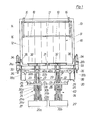
- Fig. l eine erfindungsgemässe Hub-Kipp-Vorrichtung in rückwärtiger Ansicht;
- Fig. 2 eine Vorrichtung nach
Figur 1 in Seitenansicht mit einem aufzunehmenden und einem in Anhebe-Endstellung angehobenen kleineren Behälter; - Fig. 3 eine Vorrichtung nach
Figur 1 in Seitenansicht mit eingekipptem grösserem Behälter; - Fig. 4 eine Detaildarstellung der Verriegelung bei teilweise angehobenem Hubgestell einer Vorrichtung nach
Figur 1; - Fig. 5 eine Detailansicht eines Hubgestells in Einkipp-Endstellung mit eingelegter Klinke;
- Fig. 6 eine Detaildarstellung eines Einkipp-Begrenzungshcbels;
- Fig. 7 eine Teildarstellung des mittleren und des einen Endbereiches der Schwenkwelle und
- Fig. 8 eine Schemadarstellung des in der Vorrichtung nach
Figur 1 bis 7 benutzten hydraulischen Antriebs- und Steuerungssystems.
- Fig. L an inventive lifting and tilting device in rear view;
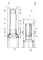
- 2 shows a device according to FIG. 1 in a side view with a smaller container to be picked up and a smaller container raised in the raised end position;
- 3 shows a device according to FIG. 1 in a side view with a larger container tipped in;
- 4 shows a detailed illustration of the locking device with the lifting frame of a device according to FIG. 1 partially raised;
- 5 shows a detailed view of a lifting frame in the tilt-in end position with an inserted pawl;
- 6 shows a detailed illustration of a tilt-in limiting lever;
- Fig. 7 is a partial view of the middle and one end region of the pivot shaft and
- F ig. 8 is a schematic representation of the hydraulic drive and control system used in the device according to FIGS. 1 to 7.
Die in der Zeichnung wiedergegebene Einschüttvorrichtung weist ein Schüttungsgehäuse 10 auf, dessen Einschüttöffnung 11 mit streifenförmigen Abdecktüchern 12 verschlossen sein kann. Im oberen Teil der Einschüttöffnung ist eine Deckelöffnungsvorrichtung 13 angebracht, die zwei im oberen Teil der Einschüttöffnung 11 schwenkbar gelagerte Hebel 14 mit hakenförmig ausgebildetem unteren Ende 15 gebildet ist. Die Hebel 14 werden durch Federn 16 in ihrer Normalstellung gehalten und dienen dazu, seitlich am Deckel von Grossraummüllgefässen angebrachte Betätigungszapfen aufzunehmen und beim Einkippen des.Grossraummüllgefässes in die Einschüttöffnung 11 den Deckel dieses Gefässes zurückzuhalten und dadurch zu öffnen. Im Rahmen der im folgenden beschriebenen neuartigen Hub-Kipp-Vorrichtung sind die beiden Hebel 14 mit einer Querstange 17 verbunden, die mit Pufferbelägen 18 versehen ist und beim Entleeren kleinerer Behälter sich mit diesen Pufferbelägen 18 gegen die Behälterwand legt und ein Überkippen der kleineren Behälter in der Einschüttöffnung 11 verhindert.The pouring device shown in the drawing has a pouring
Die neuartige Hub-Kipp-Vorrichtung 20 weist - wie die Zeichnung zeigt - zwei Einzel-Hub-Kipp-Vorrichtungen 20a und 20b auf, die gleichen Aufbau und bezüglich der vertikalen Mittelebene der Einschüttvorrichtung 10 symmetrische Anordnung aufweisen. Im Hinblick auf den gleichen Aufbau beider Einzel-Hub-Kipp-Vorrichtungen 20a und 20b wird im folgenden nur der Aufbau einer dieser Einzel-Hub-Kipp-Vorrichtungen erläutert.As shown in the drawing, the novel lifting-tilting
Beide Einzel-Hub-Kipp-Vorrichtungen 20a und 20b haben eine gemeinsame Schwenkwelle 21, die im Mittelbereich geteilt ist und für jede Einzel-Hub-Kipp-Vorrichtung 20a und 20b einen Schwenkwellenteil 21a und 21b bildet. An jedem dieser Schwenkwellentuile 21a und 21b ist ein Schwenkarm 22 angebracht. Diese Schwenkarme 22 bestehen aus zwei in seitlichem Abstand auf dem jeweiligen Schwenkwellenteil 21a bzw. 21b befestigten Schwenkarmeteile 22a und 22b, die sich parallel zueinander erstrecken und einen Hub-Zylinder 23 zwischen sich aufrehmen.Both single lift and tilt devices 20a and 20b have a
Jeder der Schwenkarme 22 trägt ein Hubgestell 24, das jeweils aus zwei vertikalen Trägerteilen 25a und 25b besteht, an deren oberen Ende ein Hubbalken 26 und an deren unteren Ende eine Widerlagerplatte 27 angebracht ist. Der Hubbalken 26 trägt sich nach oben erstreckende zahnartige Aufnahme- und Tragteile 28 und an seinem äusseren, also nach der Aussenseite der Einschüttvorrichtung 10 gerichteten Ende ein Zentriereinsatz 29. Die Hubbalken 26 und die Widerlagerplatten 27 beider Einzel-Hub-Kipp-Vorrichtungen 20a und 20b sind so angeordnet, dass sie in Ruhestellung, Anhebe-Endstellung und in Einkipp-Endstellung beider Einzel-Hub-Kipp-Vorrichtungen 20a und 20b miteinander ausgerichtet sind.Each of the
Die Verbindung zwischen dem jeweiligen Schwenkarm 22 und dem Hubgestell 24 geschieht mittels eines oberen Lenkerpaares 30a, 30b und eines unteren Lenkerpaares 31a, 31b, wobei die Kolbenstange 23a des jeweiligen Hubzylinders 23 am unteren Lenkerpaar 31a, 31b angreift. Zum Festhalten und Verriegeln des aufgenommenen Behälters ist in vertikaler Gegenüberstellung zum Hubbalken 26 auf jedem Schwenkwellenteil 21a und 21b eine Halte- und Verriegelungsleiste 32 fest angebracht, die dementsprechend die Schwenkbewegung jedes der Schwenkarme 22 mitmacht.The connection between the
Für die Erzeugung der Schwenkbewegung ist an jeden Schwenkwellenteil 21a und 21b von der jeweiligen Aussenseite der Einschüttvorrichtung lO her ein mit Druckmittelzylinder 34 ausgestatteter Schwenktrieb 33 aufgesetzt. Ferner trägt jeder Schwenkwellenteil 21a und 21b an seinem äusseren Endbereich einen Schwenkbegrenzungshebel 35, der in der Endeinkippstellung der jeweiligen Einzel-Hub-Kipp-Vorrichtung 20a bzw. 20b auf einen am Schüttungsgehäuse angebrachten Begrenzungspuffer 36 greift, der - wie in Figur 6 im einzelnen dargestellt - mit einem vom Schwenkbegrenzungshebel 35 betätigten Druckentlastungsventil verbunden sein kann. Für die Betätigung der Hub-Kipp-Vorrichtung ist ein hydraulisches System vorgesehen, das für jede Einzel-Hub-Kipp-Vorrichtung 20a und 20b ein Betätigungsventil 37a und 37b und für die Wahl für Einzelbetrieb oder gemeinsamen Betrieb beider Einzel-Hub-Kipp-Vorrichtungen 20a und 20b ein Absperr- und Umstellventil 38 enthält.To generate the swivel movement, a
Wie Figur 4 zeigt, kann jede Einzel-Hub-Kipp-Vorrichtung noch mit einem Fahr-Verriegelungshaken 39 ausgestattet sein, der an der Innenseite eines Schwenkarmeteiles 22a schwenkbar gelagert ist und bei teilweise angehobener Stellung des Hubgestells 24 über die die Kolbenstange 23a des Hubzylinders 23 mit dem unteren Lenkerpaar 31a, 31b verbindende Gelenkstange 23b gehängt wird. Durch diese Sicherung kann das Hubgestell 24 auch bei druckentlastetem Hubzylinder 23 nicht in seine untere Ruhestellung zurückkehren. Diese angehobene verriegelte Stel- lung des Hubgestells 24 eignet sich insbesondere für an Müllfahrzeugen angebrachte Hub-Kipp-Vorrichtungen, um das Hubgestell beim Fahren des Müllfahrzeugs in sicherem Abstand vom Boden zu halten.As FIG. 4 shows, each individual lifting and tilting device can also be equipped with a
Eine weitere ergänzende Sicherung ist gemäss Figur 5 dadurch möglich, dass zwischen den Trägern 25a und 25b des Hubgestells eine Verriegelungsklinke 40 schwenkbar gelagert ist, die sich aufgrund ihres eigenen Gewichtes in der Einkipp-Endstellung der jeweiligen Einzel-Hub-Kipp- Vorrichtung 20a bzw. 20b derart verschwenkt, dass sie um einen am Schwenkarm 22 angebrachten Bolzen 40a greift und dadurch verhindert, dass sich das Hubgestell 24 bei druckentlastetem Hubzylinder 23 während der Rüttelbewegung vom jeweiligen Schwenkarm 22 abhebt. Das Abheben kann erst dann einsetzen, wenn die jeweilige Einzel-Hub-Kipp- Vorrichtung 20a bzw. 20b soweit aus der Einschüttöffnung 11 zurückgeschwenkt ist, dass der Verriegelungshaken 40 den jeweiligen Bolzen 40a freigibt.A further supplementary securing is possible according to FIG. 5 in that a locking
Wie Figur 6 zeigt, ist der jeweilige Schwenkbegrenzungshebel 35 mit dem als Keilnabe 41 ausgebildeten Endbereich des jeweiligen Schwenkwellenteils 21a bzw. 21b fest verbunden und auf die als Zahnwelle oder Teilwelle ausge-' bildete Ausgangswelle des jeweiligen Schwenktriebs 33 gesetzt. An seinem Ende trägt der Schwenkbegrenzungshebel 35 eine Widerlagerplatte 42 die sich gegen einen Widerlagerpuffer 36 am Schüttungsgehäuse bewegt. Durch den Widerlagerpuffer 36 greift das Betätigungsglied 44 eines Druckentlastungsventils 43, um das Druckentlastungsventil 43 gegen die Wirkung einer Feder zu verstellen. Um die genaue Einjustierung des Umstellzeitpunktes des Druckentlastungsventils 43 zu ermöglichen, trägt der Schwenkbegrenzungshebel 35 im Bereich seiner Widerlagerplatte 42 eine Einstellschraube 45. Die Justierung kann derart vorgenommen werden, dass der Umstellzeitpunkt des Druckentlastung ventils 43 erreicht ist, wenn noch die Widerlagerplatte 42 einen geringen Abstand 4G vom Widerlagerpuffer 36 hat. Gegebenenfalls lässt sich durch die Einstellschraube auch eine Rüttelwirkung mittels des Druckentlastungsventils einrichten.As Figure 6 shows the respective
Wie aus Figur 7 ersichtlich, kann die Schwenkwelle 21 als Hohlwelle ausgebildet sein. Der eine Schwenkwellenteil 21 trägt an seinem nach der Schwenkwellenmitte hin liegenden Ende einen Verbindungs- und Lagerzapfen 47, der axial fest in das Ende des Schwellenteiles 21a eingesetzt ist. Dieser Verbindungs- und Lagerzapfen 47 hat zwei in axialem Abstand angeordnete zylindrische Abschnitte 47a und 47b, von denen der zylindrische Abschnitt 47b geringeren Durchmesser am freien Ende des Verbindungs- und Lagerzapfens 47 angeordnet ist. Auf jeden dieser zylindrischen Abschnitte 47a und 47b ist ein Nadellager 48a und 48b aufgesetzt. Zwischen dem Nadellager 48a und dem Schwenkwellenteil 21a sind noch ein Kunststoffring mit gleichem Aussendurchmesser wie der Schwenkwellenteil 21a und ein Radialdichtungsring 50 auf den Verbindungs- und Schwenkzapfen 47 aufgesetzt.As can be seen from FIG. 7, the
Der Schwenkwellenteil 21b ist im Mittelbereich der Schwenkwelle 21 als Aufnahmebuchse 51 für den Verbindungs- und Schwenkzapfen 47 ausgebildet und enthält dementsprechend einen zylindrischen Bohrungsabschnitt 51a zur Aufnahme des Nadellagers 48a und einen zylindrischen Abschnitt 51b zur Aufnahme des Nadellagers 48b. Zwischen diesen beiden zylindrischen Abschnitten 51a und 51b ist ein Abschnitt 51c gebildet, dessen Innendurchmesser grösser als der Aussendurchmesser des dort aufgenommenen Abschnittes des Verbindungs- und Drehzapfens 47 ist. Hierdurch wird ein ringförmiger Aufnahmeraum für Schmiermittel gebildet, der von aussen durch einen Schmiernippel zugänglich ist. Am freien Ende der Aufnahmebuchse 51 ist ein nochmals erweiterter Bohrungsabschnitt 51d zur Aufnahme des Radialdichtungsringes 50 und eine glatte ebene Stirnfläche zur Anlage an den Kunststoffring 49 gebildet. Durch den Sitz der Nadellager 48a und 48b sowie durch die von beiden Seiten auf die Schwenkwelle 21 aufgesetzten Schwenktriebe 33, die mit Flanschen an dem Schüttungsgehäuse gehalten sind, werden die beiden Schwenkwellenteile 21a und 21b axial zusammengehalten (vergl. Fig. l).The
Wie das Schema der Figur 8 zeigt, ist zur Betätigung und Steuerung der Hub-Kipp-Vorrichtung nach Figuren 1 bis 7 ein hydraulisches Druckmittelsystem vorgesehen, das zwei in gleicher Weise ausgebildete Druckmittelkreise A und B enthält. Jeder dieser Druckmittelkreise A und B weist eine Druckmittelquelle auf, die im dargestellten Beispiel durch jeweils einen Zweig 52a bzw. 52b eines druckunabhängigen Stromteilers in Verbindung mit einer vor diesem Stromteiler angeordneten Druckmittelpumpe 52c gebildet sein kann. Es ist aber auch möglich, diese Druckmittelquelle durch eine Zwillings-Druckmittelpumpe zu bilden, von der jeweils eine Einzelpumpe auf einen der Druckmittelkreise A bzw. B geschaltet ist. Im Druckmittelkreis A führt von dieser Druckmittelquelle 52, 52a eine Druckmittelvorlaufleitung 53a bzw. 53b zu dem jeweiligen Steuerventil 37a bzw. 37b. An dieses Steuerventil 37a bzw. 37b ist die je- weilige Druckmittelzuleitung 54a bzw. 54b angeschlossen. Die Druckmittelzuleitung 54a führt zu den in Parallelschaltung angeschlossenen Zylinder 34 des Stelltriebs 33 und Hubzylinder 23 der Einzel-Hub-Kipp-Vorrichtung 20a, während die Druckmittelzuleitung 54b in symmetrischer Anordnung zu der Parallelschaltung von Schwenktriebzylinder 34 und Hubzylinder 23 der Einzel-Hub-Kipp-Vorrichtung 20b führt. An jede der Druckmittelzuleitungen 54a und 54b ist ein Druckentlastungsventil 43 mit Betätigungselement 44 angeschlossen. Von diesen Druckentlastungsventilen 43 führen Druckentlastungsleitungen 55a bzw. 55b zu einem Druckmittelrücklaufventil 56a bzw. 56b, das in die Druckmittelrücklaufleitung 57a bzw. 57b eingesetzt ist, um den Druckmittelrücklauf und damit die Rückwärtsbewegung der Zylinder-Kolben-Aggregate 23 und 34 zu verbessern. Vom Steuerventil 37a bzw. 37b führt ferner eine Druckmittel-Kurzschlussleitung 58a bzw. 58b zu dem jeweiligen Druckmittelrücklaufventil 56a bzw. 56b. Die Druckmittel-Rücklaufleitungen 57a und 57b führen in ein Druckmittelreservoir 59, von dem die Druckmittelpumpe 52c die für das System erforderliche Druckmittelmenge ansaugt und über den jeweiligen Zweig 52a bzw. 52b des Stromteilers in den Druckmittelkreis A bzw. den Druckmittelkreis B einführt.As the diagram in FIG. 8 shows, a hydraulic pressure medium system is provided for actuating and controlling the lifting and tilting device according to FIGS. 1 to 7, which contains two pressure medium circuits A and B designed in the same way. Each of these pressure medium circuits A and B has a pressure medium source, which in the example shown can be formed by a
Zwischen die Druckmittelzuführungsleitungen 54a und 54b ist ein wahlweise in Absperrstellung und Verbindungsstellung zu bringendes Absperr- und Schaltventil 38 eingesetzt.Between the pressure
In der Darstellung der Figur 8 befinden sich das Absperr-und Schaltventil 38 in Absperrstellung die die Steuerventile 37a und 37b in Nullstellung. Bei dieser Ventilstellung strömt im Druckmittelkreis A das von der Druckmittelquelle 52a kommende Druckmittel über die Druckmittelvorlaufleitung 53a und den in Nullstellung dem Steuerventil 37a gebildeten Durchlass zu der Kurzschlussleitung 58a, um von dort durch das Rücklaufventil 56a in die Rücklaufleitung 57a und von dort zurück zum Druckmittelreservoir 59 zu gelangen. Analog aber unabhängig vom Druckmittelkreis A verläuft die Strömung im Druckmittelkreis B von der Druckmittelquelle 52b über die Druckmittelvorlaufleitung 53b, das Steuerventil 37b, die Kurzschlussleitung 38a, das Rücklaufventil 56b in die Rücklaufleitung 37b und von dort zurück zum Druckmittelreservoir 59. Wird das Steuerventil 37a in Arbeitsstellung gebracht, so ist der Druckmittclverlauf im Druckmittelkreis A von der Druckmittelquelle 52a über die Druckmittelvorlaufleitung 53a zur Druckmittelzuleitung 54a und von dort zu den Zylinder-Kolben-Aggregaten 23 und 34. Diese beiden Aggregate sind mit ihrem Kolbenquerschnitt so aufeinander abgestimmt, dass entsprechend der von dem jeweiligen Aggregat zu erbringenden Anfangsleistung der Hubzylinder 23 stärker ausgelegt ist, als der Schwenk- triebzylinder 34. Es erfolgt somit zunächst die Betäti- gung des Zylinders 23 bis der Hubvorgang nahezu abgeschlossen ist und durch den dabei auftretenden geringen Druckanstieg der Kippvorgang mittels des Schwenktriebzylinders 34 eingeleitet wird. In der Endeinkippstellung trifft dann die Einstellschraube 45 des Schwenkbegrenzungshe- bels 35 auf das Betätigungsglied 44 des Druckentlastungsventils 43 (vergl. Fig. 6). Das bisher in Schliess-Stellung gewesene Druckentlastungsventil 43 wird dann entgegen der Wirkung seiner Stellfeder in eine teilweise Öffnungsstellung gebracht, so dass eine Druckentlastung in der Druckmittelzuleitung 54a über die Druckentlastungsleitung 55a zum Druckmittelrücklaufventil 56a hin erfolgt. Wenn der Steuerabstand 46 zwischen der Betätigung des Druckentlastungsventils 43 und der Endanlage des Schwenkbe- grenzungshebels an dem Widerlagerpuffer 36 hinreichend eng eingestellt ist, wird nur eine solche Druckentlastung in der Druckmittelzuleitung 54a erfolgen, dass der Rest- druck ausreicht, um die Einzel-Hub-Kipp-Vorrichtung zu- sammen mit dem zu entleerenden Gefäss in der Endeinkipp- stellung zu halten. Stellt man jedoch den Steuerabstand 46 weiter ein, so dass die Stellschraube 45 früher auf das Betätigungselement 44 des Druckentlastungsventils 43 trifft, dann wird das Druckentlastungsventil 43 so weit geöffnet, dass ein starker Druckabfall in der Druckmittelzuleitung 54a eintritt. Dieser starke Druckmittelabfall lässt die Einzel-Hub-Kipp-Vorrichtung mit dem zu entleerenden Behälter um einen solchen Betrag zurückschwenken, dass das Druckentlastungsventil wieder geschlossen wird. Auf diese Weise lässt sich durch fortwährendes Betätigen und Freilassen des Druckentlastungsventils 43 durch den Schwenkbegrenzungshebel 35 eine Art Rüttelbewegung hervorrufen.In the illustration in FIG. 8, the shut-off and switching
Zum Zurückschwenken und Absetzen eines Behälters ist das Steuerventil 37a in seine Rücklaufstellung III zu bringen. In dieser Stellung ist die Druckmittel-Vorlauf- ! leitung 53a mit der Rücklaufleitung 57a verbunden und die Druckmittelzuleitung 54a mit der Kurzschlussleitung 58a. Das von der Druckmittelquelle 52a über die Druckmittelvorlaufleitung 53a kommende Druckmittel strömt dann durch das Rücklaufventil 56a ab, wobei es eine Saugwirkung an der Kurzschlussleitung 58a ausübt (Venturi-Ausbildung), um dadurch das Druckmittel aus der Druckmittelzuleitung und aus den Zylindern 23 und 34 nicht nur ablaufen zu lassen, sondern auch abzusaugen, insbesondere solange, bis der entleerte Behälter abgesetzt ist.To pivot back and set down a container, the
Dieser Arbeitsablauf im Druckmittelkreis A hat keinerlei Einfluss auf den Druckmittelkreis B, und zwar weder auf den Druckaufbau im Druckmittelkreis B noch auf die im Druckmittelkreis B evtl. strömende Druckmittelmenge.This workflow in the pressure medium circuit A has no e influss to the pressure medium circuit B, either on the pressure buildup in the pressure medium circuit B flowing yet to possibly in the pressure medium circuit B amount of pressure medium.
Wenn im Druckmittelkreis B für die Einzel-Hub-Kipp-Vorrichtung 20b die Betätigung des Steuerventils 37b in entsprechender Weise wie oben erläutert vorgenommen wird, treten die entsprechenden Arbeitsabläufe im Druckmittelkreis B ein, ohne Rückwirkung auf den Druckmittelkreis A.If the
Wird das Absperr- und Schaltventil 38 in Verbindungsstellung gebracht, so wird eine direkte Verbindung zwischen den Druckmittelzuleitungen 54a und 54b geschaffen, und damit eine Parallelschaltung sämtlicher Zylinder-Kolben-Aggregate 23 und 24 der gesamten Hub-Kipp-Vorrichtung 20 vorgenommen. Wird dann das Steuerventil 37a in Arbeitsstellung gebracht, so werden beide Druckmittelzuleitungen 54a und 54b von der Druckmittelquelle 52a über die Druckmittelvorlaufleitung 53a beschickt. Dies bedeutet, dass jeweils beide Hubzylinder 23 und beide Schwenktriebzylinder 34 mit der gleichen Druckmittel-Strömungsmenge beschickt werden, wie bei Einzel-Steuerung nur ein Hub- zylinder 23 und ein Schwenktriebzylinder 34. Die Arbeitsgeschwindigkeit der gesamten Hub-Kipp-rVorrichtung ist dabei etwa nur halb so gross wie diejenige der allein gesteuerten Einzel-Hub-Kipp-Vorrichtung 20a bzw. 20b.If the shut-off and switching
Die gleiche Arbeitsweise der gesamten Hub-Kipp-Vorrichtung 20 wird auch bei Betätigung des Steuerventils 37b erreicht, nur dass in solchem Fall die Druckmittelquelle 52b und die Druckmittelvorlaufleitung 43b auf beide Druckmittelzuleitungen.54a und 54b geschaltet werden. Bei Betrieb der gesamten Hub-Kipp-Vorrichtung 20 werden beide Druckentlastungsventile 43 in der Einkipp-Endstellung betätigt.The same operation of the entire lifting and tilting
Im Beispiel der Figuren 1 und 8 ist ein einziges Absperr-und Umstellventil 38 vorgesehen, das an einer Seite der Entleerungsvorrichtung angeordnet ist. Man könnte stattdessen auch zwei Absperr- und Umstellventile vorsehen, und zwar je eines an jeder Seite der Entleerungsvorrichtung. Diese beiden Absperr- und Umstellventile wären dann in analoger Weise auszubilden und in dem hydraulischen System anzuordnen, wie dies beispielsweise für elektrische Wechselschalter in elektrischen Lichtinstallationsanlagen bekannt ist. Man könnte dann die Vorrichtung an jedem beliebigen Absperr- und Umstellventil von der einen Betriebsart in die andere umstellen.In the example of FIGS. 1 and 8, a single shut-off and
Die Erfindung lässt sich auch unter Benutzung eines pneumatischen Druckmittelsystems ausführen.The invention can also be carried out using a pneumatic pressure medium system.
Claims (18)
Priority Applications (1)
| Application Number | Priority Date | Filing Date | Title |
|---|---|---|---|
| AT79104094T ATE2733T1 (en) | 1978-10-31 | 1979-10-23 | LIFT-TILT OR TILT DEVICE FOR EMPTYING CONTAINERS OF DIFFERENT SIZES. |
Applications Claiming Priority (2)
| Application Number | Priority Date | Filing Date | Title |
|---|---|---|---|
| DE2847259 | 1978-10-31 | ||
| DE19782847259 DE2847259A1 (en) | 1978-10-31 | 1978-10-31 | LIFT-TILT OR TILT DEVICE FOR EMPTYING CONTAINERS OF DIFFERENT SIZES |
Publications (2)
| Publication Number | Publication Date |
|---|---|
| EP0010719A1 true EP0010719A1 (en) | 1980-05-14 |
| EP0010719B1 EP0010719B1 (en) | 1983-03-09 |
Family
ID=6053522
Family Applications (1)
| Application Number | Title | Priority Date | Filing Date |
|---|---|---|---|
| EP79104094A Expired EP0010719B1 (en) | 1978-10-31 | 1979-10-23 | Lifting/tipping or tipping apparatus for emptying containers of varying sizes |
Country Status (17)
| Country | Link |
|---|---|
| US (1) | US4305693A (en) |
| EP (1) | EP0010719B1 (en) |
| JP (1) | JPS5561503A (en) |
| AT (1) | ATE2733T1 (en) |
| AU (1) | AU525195B2 (en) |
| BR (1) | BR7907068A (en) |
| CA (1) | CA1118704A (en) |
| CS (1) | CS230565B2 (en) |
| DD (1) | DD146929A5 (en) |
| DE (2) | DE2847259A1 (en) |
| DK (1) | DK151560C (en) |
| ES (1) | ES485586A1 (en) |
| NO (1) | NO153924C (en) |
| PL (1) | PL117599B1 (en) |
| PT (1) | PT70391A (en) |
| YU (1) | YU42654B (en) |
| ZA (1) | ZA795811B (en) |
Cited By (14)
| Publication number | Priority date | Publication date | Assignee | Title |
|---|---|---|---|---|
| WO1985003689A2 (en) * | 1984-02-20 | 1985-08-29 | Zöller-Kipper GmbH | Installation for emptying containers, particularly refuse contai ners |
| WO1986000601A1 (en) * | 1984-07-04 | 1986-01-30 | Helmut Sieke | Refuse transport vehicle |
| EP0386569A1 (en) * | 1989-03-08 | 1990-09-12 | OTTO LIFT-SYSTEME GmbH | Device for emptying containers, particularly refuse receptacles |
| US5004392A (en) * | 1984-02-20 | 1991-04-02 | Zoller-Kipper Gmbh | Device for emptying containers, especially refuse bins |
| EP0423682A1 (en) * | 1989-10-18 | 1991-04-24 | Waste Hoists Limited | Collection vehicle, apparatus for use in the vehicle and method of collecting material |
| EP0463386A1 (en) * | 1990-06-26 | 1992-01-02 | Antonicelli S.P.A. | Container tipper for automatically gripping socket-fitted refuse containers and overturning them into the body of a motor vehicle |
| EP0493571A1 (en) * | 1990-07-24 | 1992-07-08 | Stephen Wayne Holtom | Refuse loader arm. |
| US5503512A (en) * | 1992-06-22 | 1996-04-02 | Bayne Machine Works, Inc. | Residential refuse collection cart lifter with universal features |
| EP0820941A1 (en) * | 1996-07-26 | 1998-01-28 | C.L.G.Inversiones,S.L. | Lifting and tipping device for emptying refuse receptacles |
| NL1004577C2 (en) * | 1996-11-20 | 1998-05-25 | Geesink Bv | Device for lifting and / or tilting containers. |
| DE19729297A1 (en) * | 1997-07-09 | 1999-01-14 | Zoeller Kipper | Method and device for emptying waste containers into a collecting container |
| US6167795B1 (en) | 1992-06-22 | 2001-01-02 | Bayne Machine Works, Inc. | Container box and lifter features |
| US6607572B2 (en) | 2001-02-24 | 2003-08-19 | Dyson Limited | Cyclonic separating apparatus |
| CN111731887A (en) * | 2019-07-17 | 2020-10-02 | 天津市深宏科技开发有限公司 | Intelligent automatic loading system and method |
Families Citing this family (16)
| Publication number | Priority date | Publication date | Assignee | Title |
|---|---|---|---|---|
| AU8165882A (en) * | 1982-03-18 | 1983-09-22 | Wastemovers Pty. Ltd. | Container handling device |
| US4580940A (en) * | 1984-08-15 | 1986-04-08 | American Refuse Systems, Inc. | Refuse container lift/dump apparatus |
| DE3527022A1 (en) * | 1984-08-21 | 1986-03-06 | Zöller-Kipper GmbH, 6500 Mainz | TILT OR LIFT-TIP DEVICE FOR EMPTYING CONTAINERS IN COLLECTOR, PREFERABLY WASTE CONTAINER IN THE COLLECTOR OF A WASTE VEHICLE |
| US4687405A (en) * | 1985-06-24 | 1987-08-18 | Olney David I | Trash can dumping apparatus |
| FR2614011B1 (en) * | 1987-04-15 | 1991-09-06 | Plastic Omnium Cie | ROLLER BUCKET GRIPPING MECHANISM IN A BUCKET TIPPING DEVICE FOR EMPTYING IN A WASTE COLLECTION TRUCK, ESPECIALLY HOUSEHOLD GARBAGE |
| GB8724360D0 (en) * | 1987-10-17 | 1987-11-18 | Allen Motor Bodies Ltd Jack | Collection vehicle & method of tipping bin |
| DE3804090A1 (en) * | 1988-02-10 | 1989-08-24 | Edelhoff Polytechnik | WASTE COLLECTION VEHICLE |
| DE3830227A1 (en) * | 1988-09-06 | 1990-03-15 | Zoeller Kipper | LIFTING AND TILTING DEVICE FOR EMPTYING CONTAINERS IN THE BOTTOM OPENING OF A COLLECTOR, ESPECIALLY FOR EMPTYING WASTE CONTAINERS IN THE COLLECTOR OF A WASTE VEHICLE |
| DE4128955C1 (en) * | 1991-08-30 | 1992-11-05 | Zoeller Kipper | |
| US5879015A (en) * | 1992-02-10 | 1999-03-09 | Ramsey; Michael P. | Method and apparatus for receiving material |
| CA2170215C (en) * | 1995-03-28 | 2001-12-04 | Ronald E. Christenson | Tilting bin handler |
| CN1300266A (en) * | 1998-05-11 | 2001-06-20 | 策勒控股有限公司 | Lifting and tipping device |
| NL2004148C2 (en) | 2010-01-26 | 2011-07-27 | Terberg Machines | LOADING SYSTEM, DIRTY CAR AND METHOD FOR THIS. |
| CN102398755B (en) * | 2011-11-02 | 2013-07-24 | 长沙中联重科环卫机械有限公司 | Barrel overturning device and rear-mounted compression dust cart |
| FR2998280B1 (en) * | 2012-11-20 | 2016-12-30 | Pb Environnement | WASTE COLLECTION VEHICLE WITH IMPROVED LIFT-CONTAINERS |
| US10239689B2 (en) | 2015-07-27 | 2019-03-26 | The Heil Co. | Multi-use garbage truck |
Citations (4)
| Publication number | Priority date | Publication date | Assignee | Title |
|---|---|---|---|---|
| DE1017978B (en) * | 1956-05-08 | 1957-10-17 | Hans Zoeller | Trash tipping device |
| FR2153053A1 (en) * | 1971-09-17 | 1973-04-27 | Streuber Sulo Eisenwerk F | |
| DE2515929A1 (en) * | 1975-04-11 | 1976-10-21 | Edelhoff Staedtereinigung | Bin hoisting and tipping mechanism for refuse cart - has hooks to engage rims and steadying pads to engage bodies |
| DE2654542A1 (en) * | 1976-12-02 | 1978-06-08 | Zoeller Kipper | LIFT-TILT DEVICE FOR CONTAINERS, IN PARTICULAR FOR EMPTYING WASTE CONTAINERS IN WASTE COLLECTION CONTAINERS |
Family Cites Families (8)
| Publication number | Priority date | Publication date | Assignee | Title |
|---|---|---|---|---|
| GB942792A (en) * | 1959-03-12 | 1963-11-27 | Leonard Wilfred Williams Evans | Refuse collecting vehicle |
| DE1193418B (en) * | 1962-04-06 | 1965-05-20 | Eisenwerk Streuber & Lohmann G | Lifting and tipping device for emptying garbage cans into dust-free bin devices on garbage collection trucks |
| AT243183B (en) * | 1963-05-24 | 1965-10-25 | Maschf Augsburg Nuernberg Ag | Loading device for garbage trucks |
| DE1201756B (en) * | 1963-09-21 | 1965-09-23 | Kloeckner Humboldt Deutz Ag | Lifting and tilting device for emptying garbage cans in garbage trucks |
| DE1240776B (en) * | 1964-02-15 | 1967-05-18 | Elisabeth Zoeller Geb Kehl | Lift and tilt device for containers, especially for emptying garbage cans in garbage trucks |
| DE1231616B (en) * | 1964-07-24 | 1966-12-29 | Heinz Fritz Reichenkron Dipl I | Lift and tilt device on garbage collection trolleys for dust-free emptying of garbage cans of various sizes |
| DE1248541B (en) * | 1965-08-12 | 1967-08-24 | Streuber Sulo Eisenwerk F | Lifting and tipping device for emptying garbage cans into dust-free inserting devices on garbage collection trucks |
| US3738516A (en) * | 1972-07-31 | 1973-06-12 | L Wells | Container lifting mechanism |
-
1978
- 1978-10-31 DE DE19782847259 patent/DE2847259A1/en not_active Ceased
-
1979
- 1979-10-23 AT AT79104094T patent/ATE2733T1/en not_active IP Right Cessation
- 1979-10-23 DE DE7979104094T patent/DE2965001D1/en not_active Expired
- 1979-10-23 EP EP79104094A patent/EP0010719B1/en not_active Expired
- 1979-10-24 NO NO793414A patent/NO153924C/en unknown
- 1979-10-24 DK DK447479A patent/DK151560C/en not_active IP Right Cessation
- 1979-10-30 ZA ZA00795811A patent/ZA795811B/en unknown
- 1979-10-30 AU AU52320/79A patent/AU525195B2/en not_active Ceased
- 1979-10-30 CS CS797375A patent/CS230565B2/en unknown
- 1979-10-30 US US06/089,518 patent/US4305693A/en not_active Expired - Lifetime
- 1979-10-30 CA CA000338719A patent/CA1118704A/en not_active Expired
- 1979-10-30 PT PT70391A patent/PT70391A/en unknown
- 1979-10-31 JP JP14002579A patent/JPS5561503A/en active Granted
- 1979-10-31 BR BR7907068A patent/BR7907068A/en not_active IP Right Cessation
- 1979-10-31 YU YU2661/79A patent/YU42654B/en unknown
- 1979-10-31 DD DD79216591A patent/DD146929A5/en not_active IP Right Cessation
- 1979-10-31 PL PL1979219360A patent/PL117599B1/en unknown
- 1979-10-31 ES ES485586A patent/ES485586A1/en not_active Expired
Patent Citations (4)
| Publication number | Priority date | Publication date | Assignee | Title |
|---|---|---|---|---|
| DE1017978B (en) * | 1956-05-08 | 1957-10-17 | Hans Zoeller | Trash tipping device |
| FR2153053A1 (en) * | 1971-09-17 | 1973-04-27 | Streuber Sulo Eisenwerk F | |
| DE2515929A1 (en) * | 1975-04-11 | 1976-10-21 | Edelhoff Staedtereinigung | Bin hoisting and tipping mechanism for refuse cart - has hooks to engage rims and steadying pads to engage bodies |
| DE2654542A1 (en) * | 1976-12-02 | 1978-06-08 | Zoeller Kipper | LIFT-TILT DEVICE FOR CONTAINERS, IN PARTICULAR FOR EMPTYING WASTE CONTAINERS IN WASTE COLLECTION CONTAINERS |
Cited By (22)
| Publication number | Priority date | Publication date | Assignee | Title |
|---|---|---|---|---|
| WO1985003689A2 (en) * | 1984-02-20 | 1985-08-29 | Zöller-Kipper GmbH | Installation for emptying containers, particularly refuse contai ners |
| WO1985003689A3 (en) * | 1984-02-20 | 1985-10-24 | Zoeller Kipper | Installation for emptying containers, particularly refuse contai ners |
| US5004392A (en) * | 1984-02-20 | 1991-04-02 | Zoller-Kipper Gmbh | Device for emptying containers, especially refuse bins |
| WO1986000601A1 (en) * | 1984-07-04 | 1986-01-30 | Helmut Sieke | Refuse transport vehicle |
| EP0386569A1 (en) * | 1989-03-08 | 1990-09-12 | OTTO LIFT-SYSTEME GmbH | Device for emptying containers, particularly refuse receptacles |
| GB2237791B (en) * | 1989-10-18 | 1994-01-26 | Waste Hoists Ltd | Collection vehicle, apparatus for use in the vehicle and method of collecting material |
| US5145305A (en) * | 1989-10-18 | 1992-09-08 | Waste Hoists Limited | Collection vehicle, apparatus for use in the vehicle and method of collecting material |
| EP0423682A1 (en) * | 1989-10-18 | 1991-04-24 | Waste Hoists Limited | Collection vehicle, apparatus for use in the vehicle and method of collecting material |
| GB2237791A (en) * | 1989-10-18 | 1991-05-15 | Waste Hoists Ltd | Refuse collection vehicle. |
| EP0463386A1 (en) * | 1990-06-26 | 1992-01-02 | Antonicelli S.P.A. | Container tipper for automatically gripping socket-fitted refuse containers and overturning them into the body of a motor vehicle |
| EP0493571A1 (en) * | 1990-07-24 | 1992-07-08 | Stephen Wayne Holtom | Refuse loader arm. |
| EP0493571A4 (en) * | 1990-07-24 | 1994-06-22 | Stephen Wayne Holtom | Refuse loader arm |
| US6167795B1 (en) | 1992-06-22 | 2001-01-02 | Bayne Machine Works, Inc. | Container box and lifter features |
| US5503512A (en) * | 1992-06-22 | 1996-04-02 | Bayne Machine Works, Inc. | Residential refuse collection cart lifter with universal features |
| EP0820941A1 (en) * | 1996-07-26 | 1998-01-28 | C.L.G.Inversiones,S.L. | Lifting and tipping device for emptying refuse receptacles |
| NL1004577C2 (en) * | 1996-11-20 | 1998-05-25 | Geesink Bv | Device for lifting and / or tilting containers. |
| EP0844198A1 (en) | 1996-11-20 | 1998-05-27 | Geesink B.V. | Device for lifting and/or tilting containers |
| DE19729297A1 (en) * | 1997-07-09 | 1999-01-14 | Zoeller Kipper | Method and device for emptying waste containers into a collecting container |
| WO1999002433A1 (en) | 1997-07-09 | 1999-01-21 | Zöller-Kipper GmbH | Method and device for emptying refuse containers in a collecting container |
| DE19729297C2 (en) * | 1997-07-09 | 1999-07-15 | Zoeller Kipper | Method and device for emptying waste containers into a collecting container |
| US6607572B2 (en) | 2001-02-24 | 2003-08-19 | Dyson Limited | Cyclonic separating apparatus |
| CN111731887A (en) * | 2019-07-17 | 2020-10-02 | 天津市深宏科技开发有限公司 | Intelligent automatic loading system and method |
Also Published As
| Publication number | Publication date |
|---|---|
| DK151560B (en) | 1987-12-14 |
| CS230565B2 (en) | 1984-08-13 |
| CA1118704A (en) | 1982-02-23 |
| JPH0124681B2 (en) | 1989-05-12 |
| PT70391A (en) | 1979-11-01 |
| YU266179A (en) | 1983-12-31 |
| DE2847259A1 (en) | 1980-05-08 |
| NO793414L (en) | 1980-05-02 |
| ATE2733T1 (en) | 1983-03-15 |
| ZA795811B (en) | 1980-10-29 |
| PL219360A1 (en) | 1980-06-02 |
| JPS5561503A (en) | 1980-05-09 |
| EP0010719B1 (en) | 1983-03-09 |
| DE2965001D1 (en) | 1983-04-14 |
| DK151560C (en) | 1988-05-30 |
| PL117599B1 (en) | 1981-08-31 |
| AU5232079A (en) | 1980-05-08 |
| DD146929A5 (en) | 1981-03-11 |
| NO153924B (en) | 1986-03-10 |
| DK447479A (en) | 1980-05-01 |
| ES485586A1 (en) | 1980-06-16 |
| NO153924C (en) | 1986-06-18 |
| AU525195B2 (en) | 1982-10-21 |
| YU42654B (en) | 1988-10-31 |
| US4305693A (en) | 1981-12-15 |
| BR7907068A (en) | 1980-06-24 |
Similar Documents
| Publication | Publication Date | Title |
|---|---|---|
| EP0010719B1 (en) | Lifting/tipping or tipping apparatus for emptying containers of varying sizes | |
| DE2654542C3 (en) | Lift and tilt device for containers, in particular for emptying refuse containers into refuse collection containers. | |
| DE3509171A1 (en) | DEVICE FOR COMPACTING SOLID WASTE | |
| DE4102064A1 (en) | WASTE COLLECTING VEHICLE WITH A LIFTING AND TILTING DEVICE FOR RECEIVING AND EMPTYING WASTE CONTAINERS IN A TUBE OPENING | |
| DE2708251C2 (en) | Truck | |
| DE4005968C2 (en) | Garbage collection vehicle | |
| DE2515929C2 (en) | Device for emptying rubbish bins | |
| DE4441551C1 (en) | Device for lifting and emptying containers for recycling materials | |
| DE649350C (en) | Rubbish bin | |
| DE102021117999B3 (en) | Lift-tilt device | |
| DE1248541B (en) | Lifting and tipping device for emptying garbage cans into dust-free inserting devices on garbage collection trucks | |
| EP0690014B1 (en) | Lifting and tipping device for emptying refuse receptacles | |
| EP0574374A1 (en) | Refuse collecting container with a variable compartment volume | |
| EP0338492A2 (en) | Split-container for the segregated collection of different materials | |
| EP0386569A1 (en) | Device for emptying containers, particularly refuse receptacles | |
| DD296658A5 (en) | MUELLSAMMELFAHRZEUG | |
| DE3016146A1 (en) | SCHUERFKÜBEL FOR FASTENING ON A VEHICLE | |
| DE2817599A1 (en) | VEHICLE EQUIPPED WITH DEVICE FOR PICK-UP FROM THE FLOOR, TRANSPORTATION, TILTING AND PLACING ON THE FLOOR OF A CONTAINER OR BOX, IN PARTICULAR A CONTAINER FOR PICKING UP WASTE | |
| DE4331750A1 (en) | Refuse-collecting vehicle | |
| EP0763488B1 (en) | Refuse collection vehicle | |
| DE19952483C1 (en) | Locking device for adjacent lifting and tipping devices of refuse collection vehicle has locking element coupled for operation via pivot arm of one lifting and tipping device | |
| DE2524622A1 (en) | Vehicle mounted emptier for beaker shaped buck,ets - has hydraulic cylinder to assist tipping and two bucket grips | |
| DE2316310C3 (en) | Garbage truck with intermediate storage for picking up garbage from household garbage bins | |
| DE4315412A1 (en) | Lifting and tilting apparatus for a refuse collection vehicle | |
| DE1193418B (en) | Lifting and tipping device for emptying garbage cans into dust-free bin devices on garbage collection trucks |
Legal Events
| Date | Code | Title | Description |
|---|---|---|---|
| PUAI | Public reference made under article 153(3) epc to a published international application that has entered the european phase |
Free format text: ORIGINAL CODE: 0009012 |
|
| AK | Designated contracting states |
Designated state(s): AT BE CH DE FR GB IT NL SE |
|
| 17P | Request for examination filed |
Effective date: 19801111 |
|
| ITF | It: translation for a ep patent filed |
Owner name: MODIANO & ASSOCIATI S.R.L. |
|
| GRAA | (expected) grant |
Free format text: ORIGINAL CODE: 0009210 |
|
| AK | Designated contracting states |
Designated state(s): AT BE CH DE FR GB IT NL SE |
|
| REF | Corresponds to: |
Ref document number: 2733 Country of ref document: AT Date of ref document: 19830315 Kind code of ref document: T |
|
| REF | Corresponds to: |
Ref document number: 2965001 Country of ref document: DE Date of ref document: 19830414 |
|
| ET | Fr: translation filed | ||
| PLBI | Opposition filed |
Free format text: ORIGINAL CODE: 0009260 |
|
| 26 | Opposition filed |
Opponent name: FAUN-WERKE NUERNBERG KOMMUNALFAHRZEUGE UND LASTKRA Effective date: 19831209 |
|
| PLBN | Opposition rejected |
Free format text: ORIGINAL CODE: 0009273 |
|
| STAA | Information on the status of an ep patent application or granted ep patent |
Free format text: STATUS: OPPOSITION REJECTED |
|
| 27O | Opposition rejected |
Effective date: 19850131 |
|
| NLR2 | Nl: decision of opposition | ||
| ITTA | It: last paid annual fee | ||
| EAL | Se: european patent in force in sweden |
Ref document number: 79104094.2 |
|
| PGFP | Annual fee paid to national office [announced via postgrant information from national office to epo] |
Ref country code: FR Payment date: 19971016 Year of fee payment: 19 |
|
| PGFP | Annual fee paid to national office [announced via postgrant information from national office to epo] |
Ref country code: GB Payment date: 19971020 Year of fee payment: 19 |
|
| PGFP | Annual fee paid to national office [announced via postgrant information from national office to epo] |
Ref country code: SE Payment date: 19971021 Year of fee payment: 19 Ref country code: BE Payment date: 19971021 Year of fee payment: 19 Ref country code: AT Payment date: 19971021 Year of fee payment: 19 |
|
| PGFP | Annual fee paid to national office [announced via postgrant information from national office to epo] |
Ref country code: CH Payment date: 19971022 Year of fee payment: 19 |
|
| PGFP | Annual fee paid to national office [announced via postgrant information from national office to epo] |
Ref country code: NL Payment date: 19971029 Year of fee payment: 19 |
|
| PGFP | Annual fee paid to national office [announced via postgrant information from national office to epo] |
Ref country code: DE Payment date: 19971117 Year of fee payment: 19 |
|
| PG25 | Lapsed in a contracting state [announced via postgrant information from national office to epo] |
Ref country code: GB Free format text: LAPSE BECAUSE OF NON-PAYMENT OF DUE FEES Effective date: 19981023 Ref country code: AT Free format text: LAPSE BECAUSE OF NON-PAYMENT OF DUE FEES Effective date: 19981023 |
|
| PG25 | Lapsed in a contracting state [announced via postgrant information from national office to epo] |
Ref country code: SE Free format text: LAPSE BECAUSE OF NON-PAYMENT OF DUE FEES Effective date: 19981024 |
|
| PG25 | Lapsed in a contracting state [announced via postgrant information from national office to epo] |
Ref country code: CH Free format text: LAPSE BECAUSE OF NON-PAYMENT OF DUE FEES Effective date: 19981031 Ref country code: BE Free format text: LAPSE BECAUSE OF NON-PAYMENT OF DUE FEES Effective date: 19981031 |
|
| BERE | Be: lapsed |
Owner name: ZOLLER-KIPPER G.M.B.H. Effective date: 19981031 |
|
| PG25 | Lapsed in a contracting state [announced via postgrant information from national office to epo] |
Ref country code: NL Free format text: LAPSE BECAUSE OF NON-PAYMENT OF DUE FEES Effective date: 19990501 |
|
| REG | Reference to a national code |
Ref country code: CH Ref legal event code: PL |
|
| GBPC | Gb: european patent ceased through non-payment of renewal fee |
Effective date: 19981023 |
|
| EUG | Se: european patent has lapsed |
Ref document number: 79104094.2 |
|
| PG25 | Lapsed in a contracting state [announced via postgrant information from national office to epo] |
Ref country code: FR Free format text: LAPSE BECAUSE OF NON-PAYMENT OF DUE FEES Effective date: 19990630 |
|
| NLV4 | Nl: lapsed or anulled due to non-payment of the annual fee |
Effective date: 19990501 |
|
| REG | Reference to a national code |
Ref country code: FR Ref legal event code: ST |
|
| PG25 | Lapsed in a contracting state [announced via postgrant information from national office to epo] |
Ref country code: DE Free format text: LAPSE BECAUSE OF NON-PAYMENT OF DUE FEES Effective date: 19990803 |